45
0349 300 076 Validforserialno.736--xxx--xxxx 080529 Mig C141/C151 Mag C171/C201/C251 Origo Service manual
| Date post: | 04-Apr-2018 |
| Category: |
Documents |
| Upload: | phungxuyen |
| View: | 223 times |
| Download: | 0 times |
0349 300 076 Valid for serial no. 736--xxx--xxxx080529
Mig C141/C151
Mag C171/C201/C251
Origo
Service manual
-- 2 --TOCe
READ THIS FIRST 4. . . . . . . . . . . . . . . . . . . . . . . . . . . . . . . . . . . . . . . . . . . . . . . . . . . . . . . . . . . . . . . . .INTRODUCTION 4. . . . . . . . . . . . . . . . . . . . . . . . . . . . . . . . . . . . . . . . . . . . . . . . . . . . . . . . . . . . . . . . . . .TECHNICAL DATA 5. . . . . . . . . . . . . . . . . . . . . . . . . . . . . . . . . . . . . . . . . . . . . . . . . . . . . . . . . . . . . . . . .WIRING DIAGRAM, Mig C141 / C151 7. . . . . . . . . . . . . . . . . . . . . . . . . . . . . . . . . . . . . . . . . . . . . . . .Component description 7. . . . . . . . . . . . . . . . . . . . . . . . . . . . . . . . . . . . . . . . . . . . . . . . . . . . . . . . . .Mig C141 8. . . . . . . . . . . . . . . . . . . . . . . . . . . . . . . . . . . . . . . . . . . . . . . . . . . . . . . . . . . . . . . . . . . . . . .Mig C151 9. . . . . . . . . . . . . . . . . . . . . . . . . . . . . . . . . . . . . . . . . . . . . . . . . . . . . . . . . . . . . . . . . . . . . . .
DESCRIPTION OF OPERATION 10. . . . . . . . . . . . . . . . . . . . . . . . . . . . . . . . . . . . . . . . . . . . . . . . . . . . .AP1 Control board 10. . . . . . . . . . . . . . . . . . . . . . . . . . . . . . . . . . . . . . . . . . . . . . . . . . . . . . . . . . . . . .AP1:1 Control circuit 11. . . . . . . . . . . . . . . . . . . . . . . . . . . . . . . . . . . . . . . . . . . . . . . . . . . . . . . . . . . . . .AP1:2 Thermal overload cutout 11. . . . . . . . . . . . . . . . . . . . . . . . . . . . . . . . . . . . . . . . . . . . . . . . . . . . .AP1:3 RFI suppression and base load resistors 11. . . . . . . . . . . . . . . . . . . . . . . . . . . . . . . . . . . . . .AP1:4 Motor drive circuit 11. . . . . . . . . . . . . . . . . . . . . . . . . . . . . . . . . . . . . . . . . . . . . . . . . . . . . . . . . .AP1 -- Mig C141 / C151 component positions 12. . . . . . . . . . . . . . . . . . . . . . . . . . . . . . . . . . . . . . . .
WIRING DIAGRAM, Mag C171 / C201 13. . . . . . . . . . . . . . . . . . . . . . . . . . . . . . . . . . . . . . . . . . . . . . . .Component description 13. . . . . . . . . . . . . . . . . . . . . . . . . . . . . . . . . . . . . . . . . . . . . . . . . . . . . . . . . .Mag C171 15. . . . . . . . . . . . . . . . . . . . . . . . . . . . . . . . . . . . . . . . . . . . . . . . . . . . . . . . . . . . . . . . . . . . . . .Mag C201 16. . . . . . . . . . . . . . . . . . . . . . . . . . . . . . . . . . . . . . . . . . . . . . . . . . . . . . . . . . . . . . . . . . . . . . .
DESCRIPTION OF OPERATION 17. . . . . . . . . . . . . . . . . . . . . . . . . . . . . . . . . . . . . . . . . . . . . . . . . . . . .AP1 Control board 17. . . . . . . . . . . . . . . . . . . . . . . . . . . . . . . . . . . . . . . . . . . . . . . . . . . . . . . . . . . . . .AP1:1 Power supply 19. . . . . . . . . . . . . . . . . . . . . . . . . . . . . . . . . . . . . . . . . . . . . . . . . . . . . . . . . . . . . .AP1:2 Reference circuit 19. . . . . . . . . . . . . . . . . . . . . . . . . . . . . . . . . . . . . . . . . . . . . . . . . . . . . . . . . . .AP1:3,4,5 Start / Stop, Thermal overload, Spot welding 20. . . . . . . . . . . . . . . . . . . . . . . . . . . . . . . .AP1:6 Burnback time 21. . . . . . . . . . . . . . . . . . . . . . . . . . . . . . . . . . . . . . . . . . . . . . . . . . . . . . . . . . . . .AP1:7 Control amplifier and pulse width modulator 21. . . . . . . . . . . . . . . . . . . . . . . . . . . . . . . . . . . .AP1:8,9 Motor driving / braking 22. . . . . . . . . . . . . . . . . . . . . . . . . . . . . . . . . . . . . . . . . . . . . . . . . . . . .AP1 -- Mag C171 / C201 component positions 23. . . . . . . . . . . . . . . . . . . . . . . . . . . . . . . . . . . . . . . .
WIRING DIAGRAM, Mag C251 24. . . . . . . . . . . . . . . . . . . . . . . . . . . . . . . . . . . . . . . . . . . . . . . . . . . . . .Component description 24. . . . . . . . . . . . . . . . . . . . . . . . . . . . . . . . . . . . . . . . . . . . . . . . . . . . . . . . . .Mag C251 26. . . . . . . . . . . . . . . . . . . . . . . . . . . . . . . . . . . . . . . . . . . . . . . . . . . . . . . . . . . . . . . . . . . . . . .
DESCRIPTION OF OPERATION 27. . . . . . . . . . . . . . . . . . . . . . . . . . . . . . . . . . . . . . . . . . . . . . . . . . . . .AP1 Control board 27. . . . . . . . . . . . . . . . . . . . . . . . . . . . . . . . . . . . . . . . . . . . . . . . . . . . . . . . . . . . . .AP1:1 Power supply 27. . . . . . . . . . . . . . . . . . . . . . . . . . . . . . . . . . . . . . . . . . . . . . . . . . . . . . . . . . . . . .AP1:2 Start / Stop 27. . . . . . . . . . . . . . . . . . . . . . . . . . . . . . . . . . . . . . . . . . . . . . . . . . . . . . . . . . . . . . . .AP1:3 Spot welding 28. . . . . . . . . . . . . . . . . . . . . . . . . . . . . . . . . . . . . . . . . . . . . . . . . . . . . . . . . . . . . . .AP1:4 Wire feed speed 28. . . . . . . . . . . . . . . . . . . . . . . . . . . . . . . . . . . . . . . . . . . . . . . . . . . . . . . . . . . .AP1:5 Motor driving / braking 29. . . . . . . . . . . . . . . . . . . . . . . . . . . . . . . . . . . . . . . . . . . . . . . . . . . . . .AP1:6 Burnback time, contactor, gas valve 30. . . . . . . . . . . . . . . . . . . . . . . . . . . . . . . . . . . . . . . . . . .AP1:7 Thermal overload cutout 30. . . . . . . . . . . . . . . . . . . . . . . . . . . . . . . . . . . . . . . . . . . . . . . . . . . . .AP1 -- Mag C251 component positions 31. . . . . . . . . . . . . . . . . . . . . . . . . . . . . . . . . . . . . . . . . . . . . .
SERVICE INSTRUCTIONS 32. . . . . . . . . . . . . . . . . . . . . . . . . . . . . . . . . . . . . . . . . . . . . . . . . . . . . . . . . .What is ESD? 32. . . . . . . . . . . . . . . . . . . . . . . . . . . . . . . . . . . . . . . . . . . . . . . . . . . . . . . . . . . . . . . . . . .Thermal switch (thermostat) replacement procedure 32. . . . . . . . . . . . . . . . . . . . . . . . . . . . . . .
INSTRUCTIONS 33. . . . . . . . . . . . . . . . . . . . . . . . . . . . . . . . . . . . . . . . . . . . . . . . . . . . . . . . . . . . . . . . . . .SAFETY 33. . . . . . . . . . . . . . . . . . . . . . . . . . . . . . . . . . . . . . . . . . . . . . . . . . . . . . . . . . . . . . . . . . . . . . . . . .INSTALLATION 35. . . . . . . . . . . . . . . . . . . . . . . . . . . . . . . . . . . . . . . . . . . . . . . . . . . . . . . . . . . . . . . . . . . .Placing 35. . . . . . . . . . . . . . . . . . . . . . . . . . . . . . . . . . . . . . . . . . . . . . . . . . . . . . . . . . . . . . . . . . . . . . . . .Assembly of components 35. . . . . . . . . . . . . . . . . . . . . . . . . . . . . . . . . . . . . . . . . . . . . . . . . . . . . . . .Electrical installation 37. . . . . . . . . . . . . . . . . . . . . . . . . . . . . . . . . . . . . . . . . . . . . . . . . . . . . . . . . . . .Mains power supply 38. . . . . . . . . . . . . . . . . . . . . . . . . . . . . . . . . . . . . . . . . . . . . . . . . . . . . . . . . . . . .OPERATION 38. . . . . . . . . . . . . . . . . . . . . . . . . . . . . . . . . . . . . . . . . . . . . . . . . . . . . . . . . . . . . . . . . . . .Connection and control devices 39. . . . . . . . . . . . . . . . . . . . . . . . . . . . . . . . . . . . . . . . . . . . . . . . . .Welding without gas 40. . . . . . . . . . . . . . . . . . . . . . . . . . . . . . . . . . . . . . . . . . . . . . . . . . . . . . . . . . . .Wire feed pressure 40. . . . . . . . . . . . . . . . . . . . . . . . . . . . . . . . . . . . . . . . . . . . . . . . . . . . . . . . . . . . . .Replacing and inserting wire 40. . . . . . . . . . . . . . . . . . . . . . . . . . . . . . . . . . . . . . . . . . . . . . . . . . . . .Overheating protection 41. . . . . . . . . . . . . . . . . . . . . . . . . . . . . . . . . . . . . . . . . . . . . . . . . . . . . . . . . .

-- 3 --TOCe
MAINTENANCE 41. . . . . . . . . . . . . . . . . . . . . . . . . . . . . . . . . . . . . . . . . . . . . . . . . . . . . . . . . . . . . . . . . . . .Inspection and cleaning 41. . . . . . . . . . . . . . . . . . . . . . . . . . . . . . . . . . . . . . . . . . . . . . . . . . . . . . . . .
FAULT TRACING 42. . . . . . . . . . . . . . . . . . . . . . . . . . . . . . . . . . . . . . . . . . . . . . . . . . . . . . . . . . . . . . . . . .ORDERING OF SPARE PARTS 42. . . . . . . . . . . . . . . . . . . . . . . . . . . . . . . . . . . . . . . . . . . . . . . . . . . . . .NOTES 43. . . . . . . . . . . . . . . . . . . . . . . . . . . . . . . . . . . . . . . . . . . . . . . . . . . . . . . . . . . . . . . . . . . . . . . . . . .
Edition 080529-- 4 --1sC1425
READ THIS FIRST
Maintenance and repair work should be performed by an experienced person, andelectrical work only by a trained electrician. Use only recommended replacement parts.
This service manual is intended for use by technicians with electrical/electronic training forhelp in connection with fault--tracing and repair.
Use the wiring diagram as a form of index for the description of operation. The circuitboard is divided into numbered blocks, which are described individually in more detail inthe description of operation. All component names in the wiring diagram are listed in thecomponent description.
This manual contains details of all design changes that have been made up to andincluding May 2008.
The OrigoTM Mig C141/C151, Mag C171/C201/C251 are designed and tested inaccordance with international and European standard IEC/EN 60974--1 and EN60974--10.On completion of service or repair work, it is the responsibility of the person(s) etc.performing the work to ensure that the product does not depart from the requirementsof the above standard.
INTRODUCTION
OrigoTM Mig C141/C151, Mag C171/C201/C251 are step controlled power sourcesin a compact design, intended for welding with solid steel, stainless steel oraluminium wire as well as tubular wire with or without shielding gas.
The possibility of welding with homogeneous wire/shielding gas and welding withgasless tubular wire is obtained by switching the + and -- connections on theswitching terminal by the wire feed unit.
Edition 080529-- 5 --1sC1425
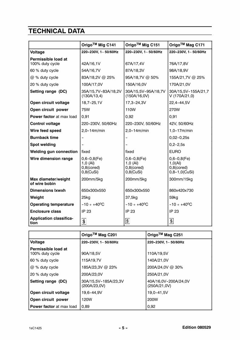
TECHNICAL DATA
OrigoTM Mig C141 OrigoTM Mig C151 OrigoTM Mag C171
Voltage 220--230V, 1∼ 50/60Hz 220--230V, 1∼ 50/60Hz 220--230V, 1∼ 50/60Hz
Permissible load at100% duty cycle 42A/16,1V 67A/17,4V 76A/17,8V
60 % duty cycle 54A/16,7V 87A/18,3V 98A/18,9V
@ % duty cycle 83A/18,2V @ 25% 95A/18,7V @ 50% 155A/21,7V @ 25%
20 % duty cycle 100A/17,0V 150A/16,0V 170A/21,0V
Setting range (DC) 35A/15,7V--83A/18,2V(130A/13,4)
30A/15,5V--95A/18,7V(150A/16,0V)
30A/15,5V--155A/21,7V (170A/21,0)
Open circuit voltage 18,7--25,1V 17,3--24,3V 22,4--44,5V
Open circuit power 75W 110W 270W
Power factor at max load 0,91 0,92 0,91
Control voltage 220--230V, 50/60Hz 220--230V, 50/60Hz 42V, 50/60Hz
Wire feed speed 2,0--14m/min 2,0--14m/min 1,0--17m/min
Burnback time -- -- 0,02--0,25s
Spot welding -- -- 0,2--2,5s
Welding gun connection fixed fixed EURO
Wire dimension range 0,6--0,8(Fe)1,0 (Al)0,8(cored)0,8(CuSi)
0,6--0,8(Fe)1,0 (Al)0,8(cored)0,8(CuSi)
0,6--0,8(Fe)1,0(Al)0,8(cored)0,8--1,0(CuSi)
Max diameter/weightof wire bobin
200mm/5kg 200mm/5kg 300mm/15kg
Dimensions lxwxh 650x300x550 650x300x550 860x420x730
Weight 25kg 37,5kg 59kg
Operating temperature --10 ÷ +40oC --10 ÷ +40oC --10 ÷ +40oC
Enclosure class IP 23 IP 23 IP 23
Application classifica-tion
OrigoTM Mag C201 OrigoTM Mag C251
Voltage 220--230V, 1∼ 50/60Hz 220--230V, 1∼ 50/60Hz
Permissible load at100% duty cycle 90A/18,5V 110A/19,5V
60 % duty cycle 115A19,7V 140A/21,0V
@ % duty cycle 185A/23,3V @ 23% 200A/24,0V @ 30%
20 % duty cycle 200A/23,0V 250A/21,0V
Setting range (DC) 30A/15,5V--185A/23,3V(200A/23,0V)
40A/16,0V--200A/24,0V(250A/21,0V)
Open circuit voltage 19,6--44,9V 19,0--41,5V
Open circuit power 120W 200W
Power factor at max load 0,89 0,92
Edition 080529-- 6 --1sC1425
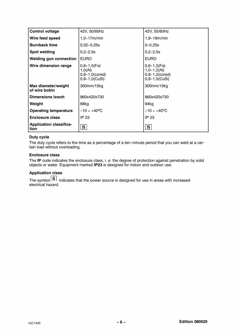
Control voltage 42V, 50/60Hz 42V, 50/60Hz
Wire feed speed 1,0--17m/min 1,9--19m/min
Burnback time 0,02--0,25s 0--0,25s
Spot welding 0,2--2,5s 0,2--2,5s
Welding gun connection EURO EURO
Wire dimension range 0,6--1,0(Fe)1,0(Al)0,8--1,0(cored)0,8--1,0(CuSi)
0,6--1,2(Fe)1,0--1,2(Al)0,8--1,2(cored)0,8--1,0(CuSi)
Max diameter/weightof wire bobin
300mm/15kg 300mm/15kg
Dimensions lxwxh 860x420x730 860x420x730
Weight 68kg 94kg
Operating temperature --10 ÷ +40oC --10 ÷ +40oC
Enclosure class IP 23 IP 23
Application classifica-tion
Duty cycleThe duty cycle refers to the time as a percentage of a ten--minute period that you can weld at a cer-tain load without overloading.
Enclosure classThe IP code indicates the enclosure class, i. e. the degree of protection against penetration by solidobjects or water. Equipment marked IP23 is designed for indoor and outdoor use.
Application class
The symbol indicates that the power source is designed for use in areas with increasedelectrical hazard.
Edition 080529-- 7 --1sC1425
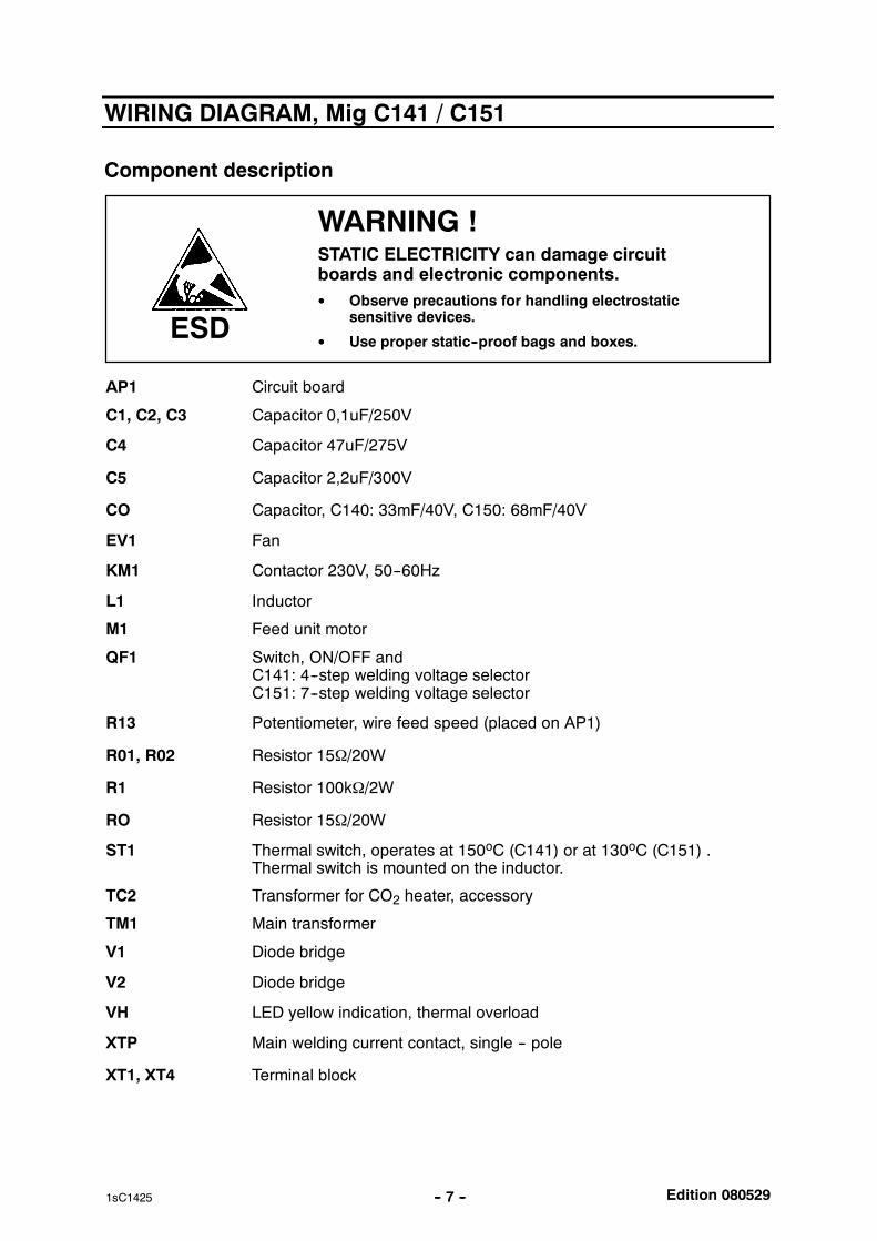
WIRING DIAGRAM, Mig C141 / C151
Component description
WARNING !STATIC ELECTRICITY can damage circuitboards and electronic components. Observe precautions for handling electrostatic
sensitive devices.
Use proper static--proof bags and boxes.ESD
AP1 Circuit board
C1, C2, C3 Capacitor 0,1uF/250V
C4 Capacitor 47uF/275V
C5 Capacitor 2,2uF/300V
CO Capacitor, C140: 33mF/40V, C150: 68mF/40V
EV1 Fan
KM1 Contactor 230V, 50--60Hz
L1 Inductor
M1 Feed unit motor
QF1 Switch, ON/OFF andC141: 4--step welding voltage selectorC151: 7--step welding voltage selector
R13 Potentiometer, wire feed speed (placed on AP1)
R01, R02 Resistor 15Ω/20W
R1 Resistor 100kΩ/2W
RO Resistor 15Ω/20W
ST1 Thermal switch, operates at 150oC (C141) or at 130oC (C151) .Thermal switch is mounted on the inductor.
TC2 Transformer for CO2 heater, accessory
TM1 Main transformer
V1 Diode bridge
V2 Diode bridge
VH LED yellow indication, thermal overload
XTP Main welding current contact, single -- pole
XT1, XT4 Terminal block
Edition 080529-- 8 --1sC1425
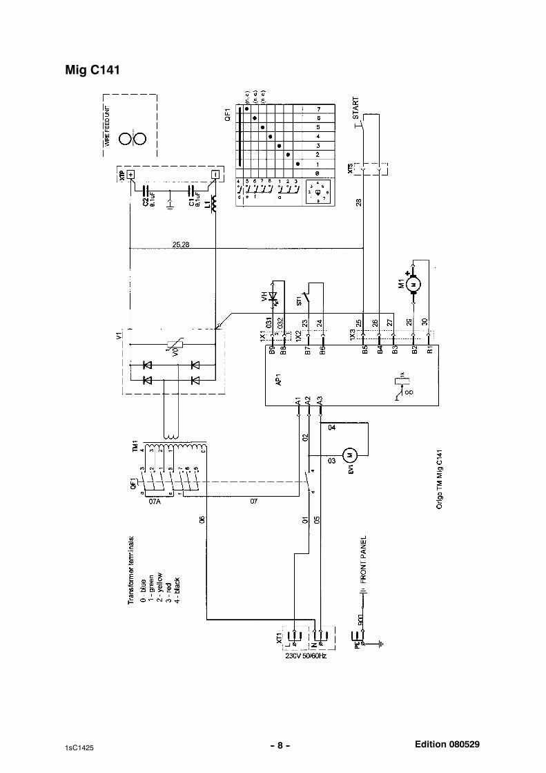
Mig C141
Edition 080529-- 9 --1sC1425
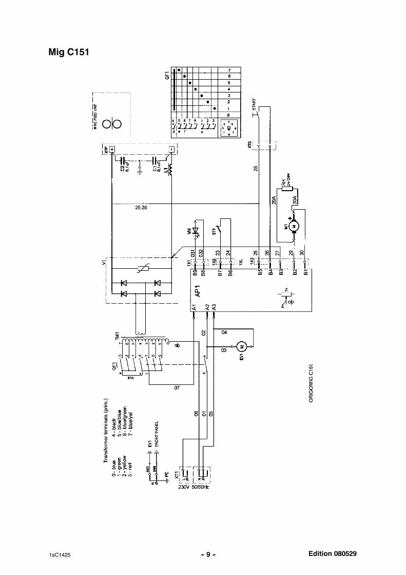
Mig C151
Edition 080529-- 10 --1sC1425
DESCRIPTION OF OPERATION
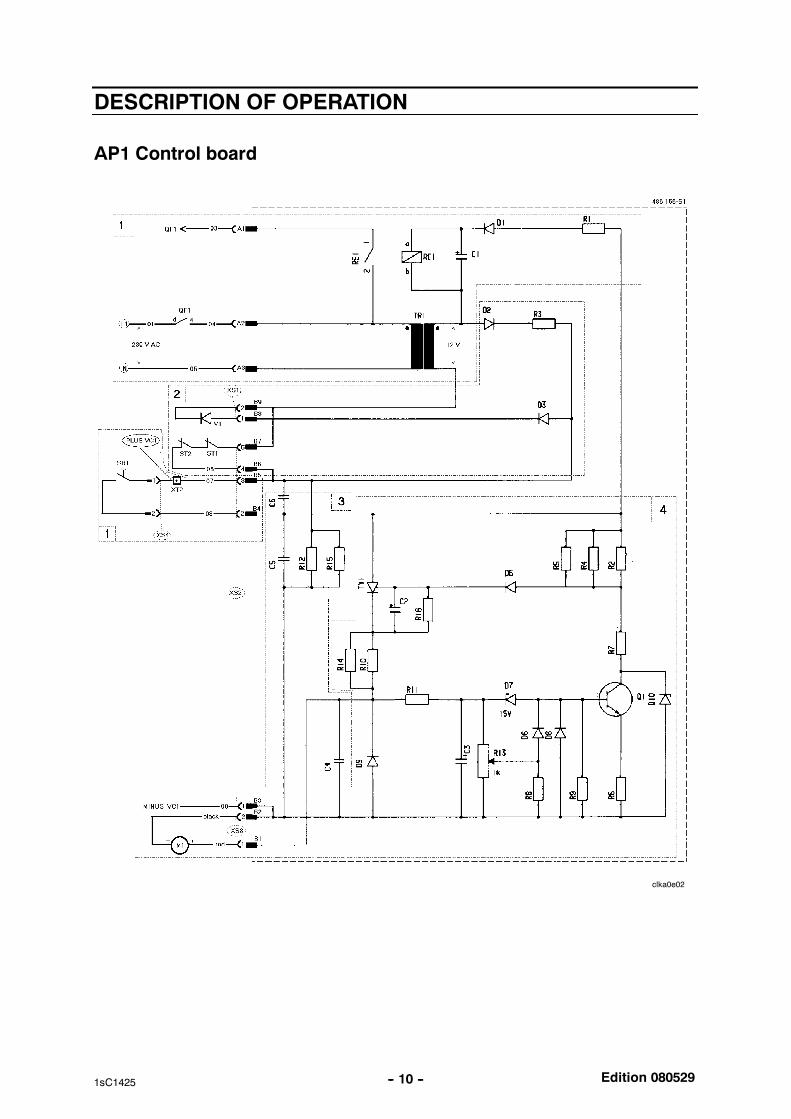
AP1 Control board
clka0e02
Edition 080529-- 11 --1sC1425
AP1:1 Control circuit
Pressing trigger switch SB1 on the welding torch energises relay RE1 fromcontrol power transformer TR1. The contacts on the relay connect maintransformer TM1 to the mains power supply.The power supply to RE1 is half--wave rectified by D1. Resistor R1 isconnected in series with the relay and drops the voltage to it. Capacitor C1(220µF) smoothes the voltage. It also delays the drop--off of relay RE1 byabout 25 ms, to provide a burnback time.
AP1:2 Thermal overload cutout
In the event of a thermal overload, thermal overload cutout ST1 interrupts thesecondary circuit from TR1, causing relay RE1 to drop off and de--energisingthe welding circuit. When not operated (i.e. with closed contacts), the cutoutsshort--circuit inputs B6 and B7.Operation of either of the cutouts is indicated by LED V1. Interruption of thecutout circuit energises the LED via D2, R3 and D3. D2 is a half--waverectifier, R3 limits the current through the LED and D3 protects it againstreverse voltage.
AP1:3 RFI suppression and base load resistors
Capacitors C4 -- C6 protect against RFI. Resistors R12 and R15 provide aminimum base load for the rectifier bridge: in addition, they act as dischargeresistors for the capacitors.
AP1:4 Motor drive circuit
The wire feed motor is powered by the rectified secondary voltage from maintransformer TM1.Pressing the welding torch trigger switch SB1 provides a supply to thyristorTY1 via contact B4 from the positive side of the main power rectifier VC1.Resistors R10 and R14 limit the motor starting current: excessive startingcurrent would demagnetise the motor. D9 is a squelch diode protectingagainst back--emf from the motor.The ignition circuit for TY1 consists of R2,R4, R5, D5 and C2.When Q1 is not conducting, operation of the circuit is as follows:If the voltage at B4 exceeds the motor voltage, C2 charges via R2, R4 and R5.When the voltage on C2 reaches the trigger voltage (0.5 -- 1.5 V), thyristor TY1fires. This means that TY1 conducts each half--cycle when Q1 is notconducting.D5 protects C2 against negative voltage when Q1 conducts.
Motor voltage control
C3, R11 and potentiometer R13 form a low--pass filter circuit for the motorsupply. R13 picks off a suitable fraction of the motor voltage for connection tothe base of Q1 via diode D6. Q1 starts to conduct at a bases voltage of 0.7 V.C2 charges more slowly, which means that thyristor TY1 fires later. Motorvoltage is lowest when R13 is in its upper position, the minimum position.The base voltage is then high and Q1 conducts. The charging time for C2becomes so long that thyristor TY1 misses some half cycles, firing only (forexample) on every third cycle.When R13 is in its lower (= maximum) position, the base voltage on Q1 is lowand Q1 does not conduct. In this state, zener diode D7 determines themaximum motor voltage.
Edition 080529-- 12 --1sC1425
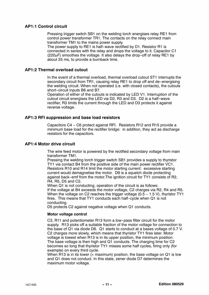
AP1 -- Mig C141 / C151 component positions
clka0e03
Edition 080529-- 13 --1sC1425
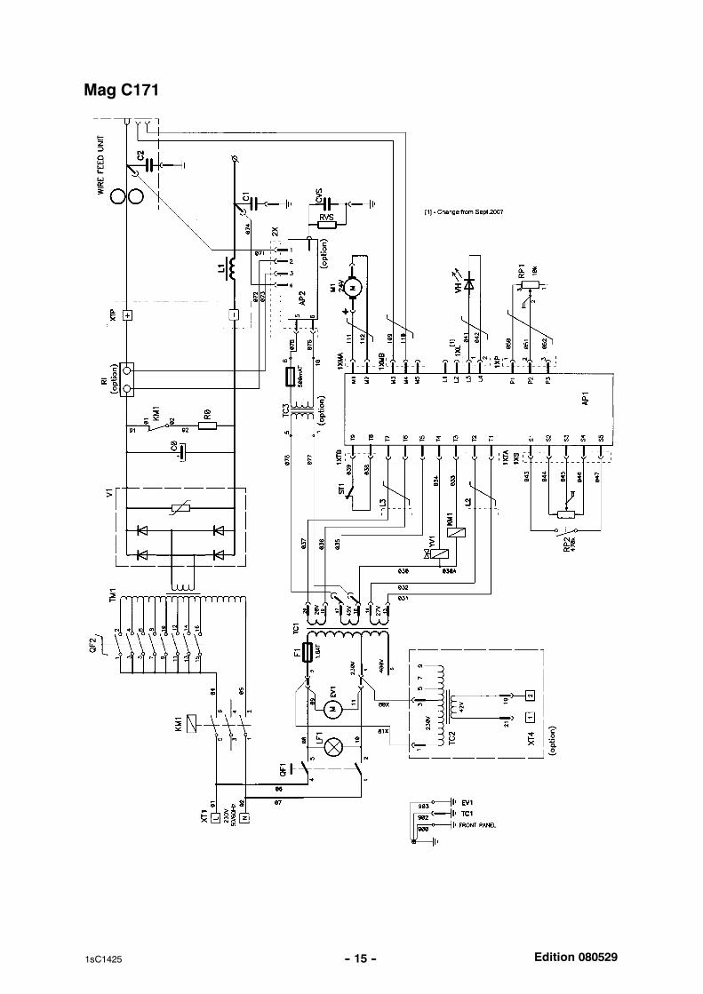
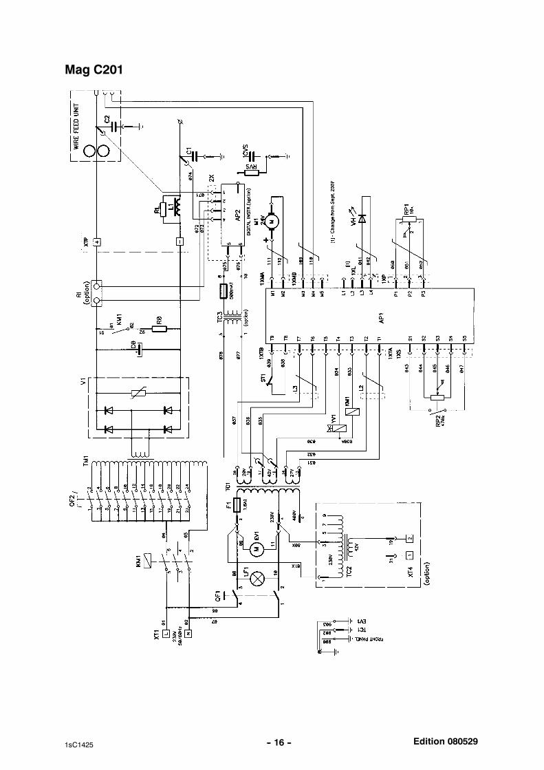
WIRING DIAGRAM, Mag C171 / C201
Component description
WARNING !STATIC ELECTRICITY can damage circuitboards and electronic components. Observe precautions for handling electrostatic
sensitive devices.
Use proper static--proof bags and boxes.ESD
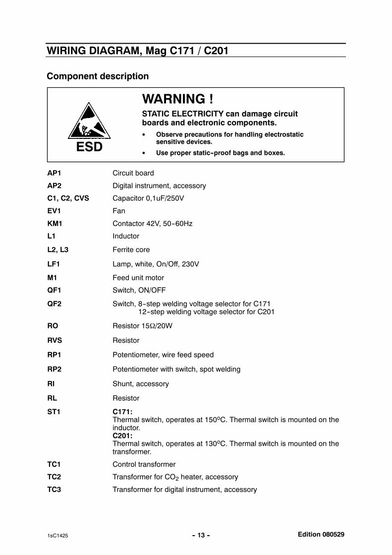
AP1 Circuit board
AP2 Digital instrument, accessory
C1, C2, CVS Capacitor 0,1uF/250V
EV1 Fan
KM1 Contactor 42V, 50--60Hz
L1 Inductor
L2, L3 Ferrite core
LF1 Lamp, white, On/Off, 230V
M1 Feed unit motor
QF1 Switch, ON/OFF
QF2 Switch, 8--step welding voltage selector for C171Switch, 12--step welding voltage selector for C201
RO Resistor 15Ω/20W
RVS Resistor
RP1 Potentiometer, wire feed speed
RP2 Potentiometer with switch, spot welding
RI Shunt, accessory
RL Resistor
ST1 C171:Thermal switch, operates at 150oC. Thermal switch is mounted on theinductor.C201:Thermal switch, operates at 130oC. Thermal switch is mounted on thetransformer.
TC1 Control transformer
TC2 Transformer for CO2 heater, accessory
TC3 Transformer for digital instrument, accessory

Edition 080529-- 14 --1sC1425
TM1 Main transformer
V1 Diode bridge
VH LED yellow indication, thermal overload
XTP Main welding current contact, single -- pole
XT1, XT4 Terminal block
YV1 Gas valve
Edition 080529-- 15 --1sC1425
Mag C171
Edition 080529-- 16 --1sC1425
Mag C201
Edition 080529-- 17 --1sC1425
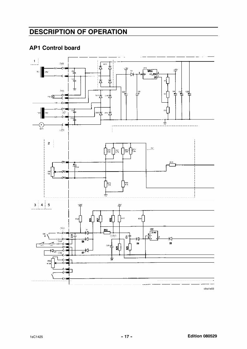
DESCRIPTION OF OPERATION
AP1 Control board
clka1e03
Edition 080529-- 18 --1sC1425
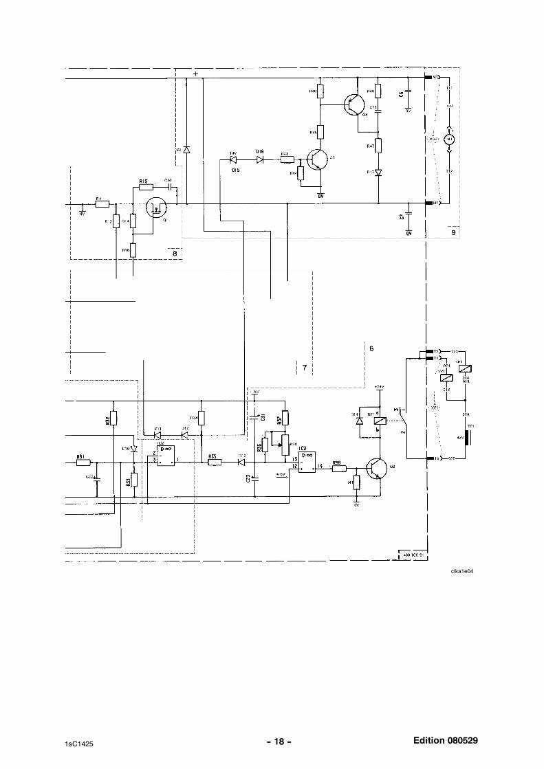
clka1e04
Edition 080529-- 19 --1sC1425
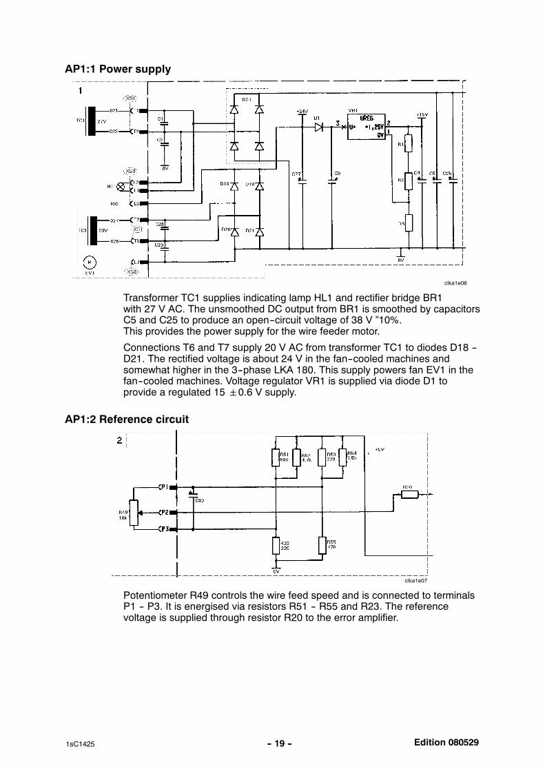
AP1:1 Power supply
clka1e06
Transformer TC1 supplies indicating lamp HL1 and rectifier bridge BR1with 27 V AC. The unsmoothed DC output from BR1 is smoothed by capacitorsC5 and C25 to produce an open--circuit voltage of 38 V ”10%.This provides the power supply for the wire feeder motor.
Connections T6 and T7 supply 20 V AC from transformer TC1 to diodes D18 --D21. The rectified voltage is about 24 V in the fan--cooled machines andsomewhat higher in the 3--phase LKA 180. This supply powers fan EV1 in thefan--cooled machines. Voltage regulator VR1 is supplied via diode D1 toprovide a regulated 150.6 V supply.
AP1:2 Reference circuit
clka1e07
Potentiometer R49 controls the wire feed speed and is connected to terminalsP1 -- P3. It is energised via resistors R51 -- R55 and R23. The referencevoltage is supplied through resistor R20 to the error amplifier.
Edition 080529-- 20 --1sC1425
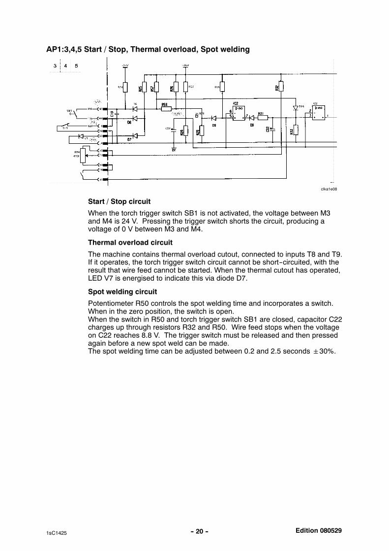
AP1:3,4,5 Start / Stop, Thermal overload, Spot welding
clka1e08
Start / Stop circuit
When the torch trigger switch SB1 is not activated, the voltage between M3and M4 is 24 V. Pressing the trigger switch shorts the circuit, producing avoltage of 0 V between M3 and M4.
Thermal overload circuit
The machine contains thermal overload cutout, connected to inputs T8 and T9.If it operates, the torch trigger switch circuit cannot be short--circuited, with theresult that wire feed cannot be started. When the thermal cutout has operated,LED V7 is energised to indicate this via diode D7.
Spot welding circuit
Potentiometer R50 controls the spot welding time and incorporates a switch.When in the zero position, the switch is open.When the switch in R50 and torch trigger switch SB1 are closed, capacitor C22charges up through resistors R32 and R50. Wire feed stops when the voltageon C22 reaches 8.8 V. The trigger switch must be released and then pressedagain before a new spot weld can be made.The spot welding time can be adjusted between 0.2 and 2.5 seconds30%.
Edition 080529-- 21 --1sC1425
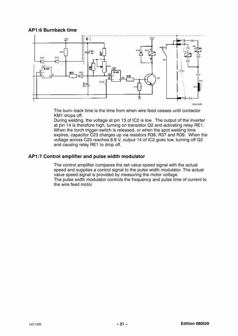
AP1:6 Burnback time
clka1e09
The burn--back time is the time from when wire feed ceases until contactorKM1 drops off.During welding, the voltage at pin 13 of IC2 is low. The output of the inverterat pin 14 is therefore high, turning on transistor Q2 and activating relay RE1.When the torch trigger switch is released, or when the spot welding timeexpires, capacitor C23 charges up via resistors R36, R37 and R38. When thevoltage across C23 reaches 8.8 V, output 14 of IC2 goes low, turning off Q2and causing relay RE1 to drop off.
AP1:7 Control amplifier and pulse width modulator
The control amplifier compares the set value speed signal with the actualspeed and supplies a control signal to the pulse width modulator. The actualvalue speed signal is provided by measuring the motor voltage.The pulse width modulator controls the frequency and pulse time of current tothe wire feed motor.
Edition 080529-- 22 --1sC1425
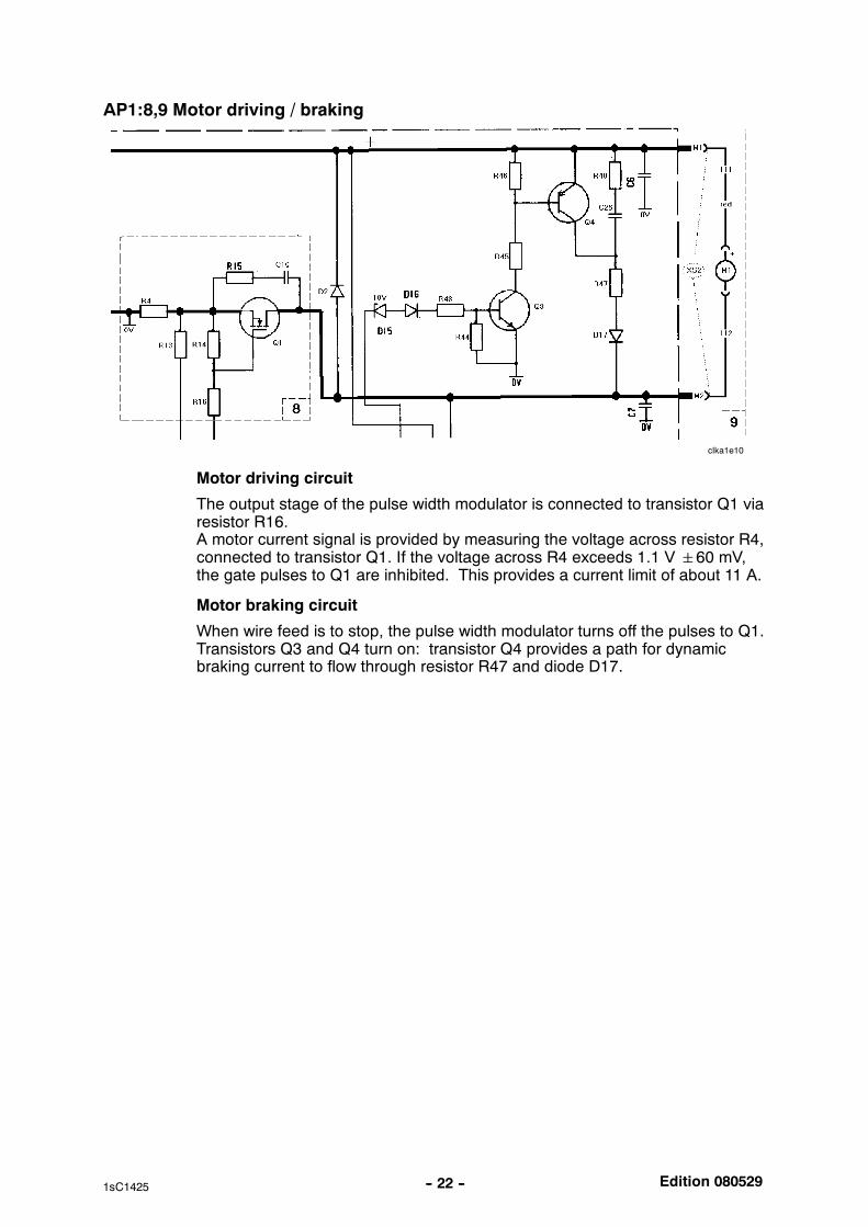
AP1:8,9 Motor driving / braking
clka1e10
Motor driving circuit
The output stage of the pulse width modulator is connected to transistor Q1 viaresistor R16.A motor current signal is provided by measuring the voltage across resistor R4,connected to transistor Q1. If the voltage across R4 exceeds 1.1 V60 mV,the gate pulses to Q1 are inhibited. This provides a current limit of about 11 A.
Motor braking circuit
When wire feed is to stop, the pulse width modulator turns off the pulses to Q1.Transistors Q3 and Q4 turn on: transistor Q4 provides a path for dynamicbraking current to flow through resistor R47 and diode D17.
Edition 080529-- 23 --1sC1425
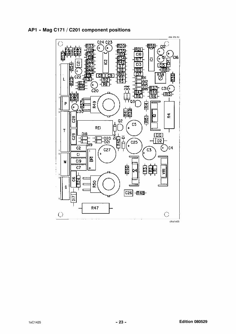
AP1 -- Mag C171 / C201 component positions
clka1e05
Edition 080529-- 24 --1sC1425
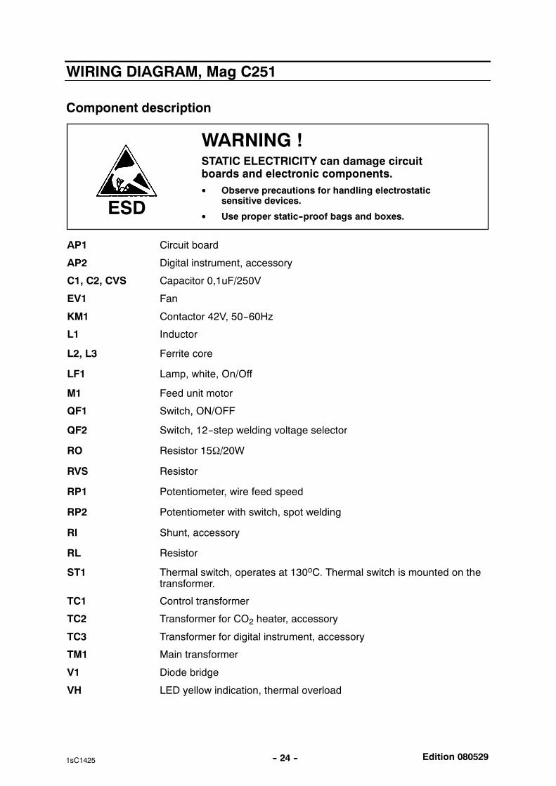
WIRING DIAGRAM, Mag C251
Component description
WARNING !STATIC ELECTRICITY can damage circuitboards and electronic components. Observe precautions for handling electrostatic
sensitive devices.
Use proper static--proof bags and boxes.ESD
AP1 Circuit board
AP2 Digital instrument, accessory
C1, C2, CVS Capacitor 0,1uF/250V
EV1 Fan
KM1 Contactor 42V, 50--60Hz
L1 Inductor
L2, L3 Ferrite core
LF1 Lamp, white, On/Off
M1 Feed unit motor
QF1 Switch, ON/OFF
QF2 Switch, 12--step welding voltage selector
RO Resistor 15Ω/20W
RVS Resistor
RP1 Potentiometer, wire feed speed
RP2 Potentiometer with switch, spot welding
RI Shunt, accessory
RL Resistor
ST1 Thermal switch, operates at 130oC. Thermal switch is mounted on thetransformer.
TC1 Control transformer
TC2 Transformer for CO2 heater, accessory
TC3 Transformer for digital instrument, accessory
TM1 Main transformer
V1 Diode bridge
VH LED yellow indication, thermal overload

Edition 080529-- 25 --1sC1425
XTP Main welding current contact, single -- pole
XT1, XT4 Terminal block
YV1 Gas valve
Edition 080529-- 26 --1sC1425
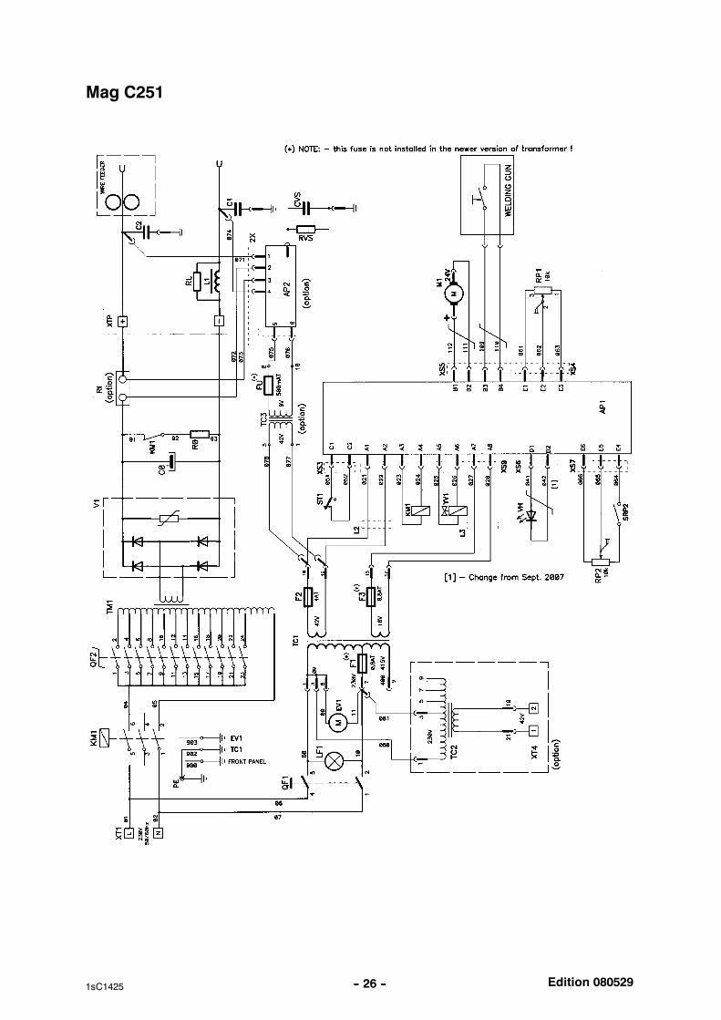
Mag C251
Edition 080529-- 27 --1sC1425
DESCRIPTION OF OPERATION
AP1 Control board
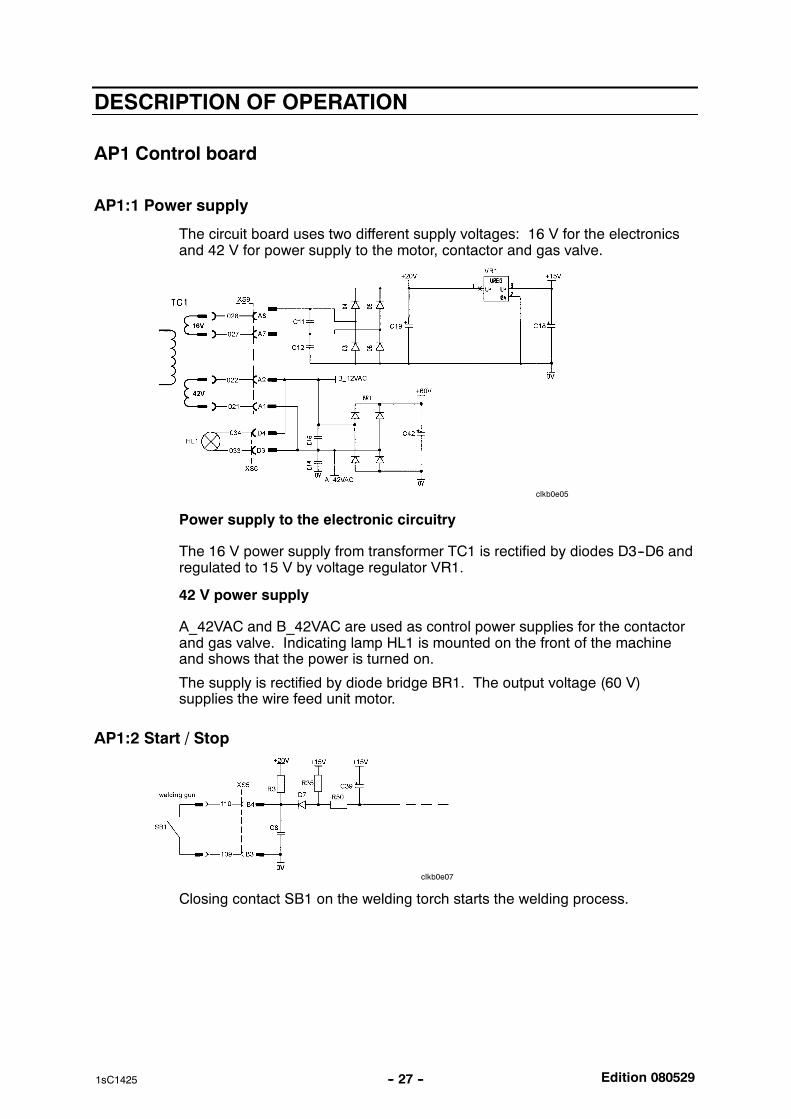
AP1:1 Power supply
The circuit board uses two different supply voltages: 16 V for the electronicsand 42 V for power supply to the motor, contactor and gas valve.
clkb0e05
Power supply to the electronic circuitry
The 16 V power supply from transformer TC1 is rectified by diodes D3--D6 andregulated to 15 V by voltage regulator VR1.
42 V power supply
A_42VAC and B_42VAC are used as control power supplies for the contactorand gas valve. Indicating lamp HL1 is mounted on the front of the machineand shows that the power is turned on.
The supply is rectified by diode bridge BR1. The output voltage (60 V)supplies the wire feed unit motor.
AP1:2 Start / Stop
clkb0e07
Closing contact SB1 on the welding torch starts the welding process.
Edition 080529-- 28 --1sC1425
T 1
0
0
0
0
1
1
1
1
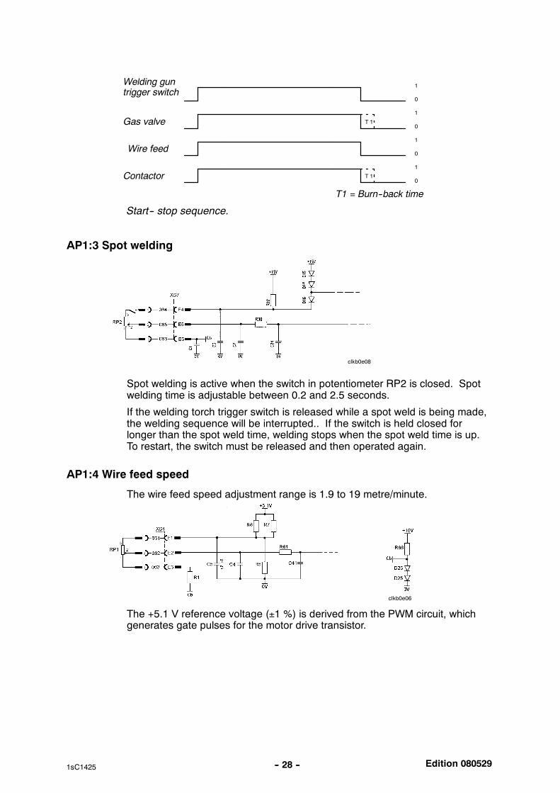
Gas valve
Welding guntrigger switch
Wire feed
Contactor
T1 = Burn--back time
T 1
Start-- stop sequence.
AP1:3 Spot welding
clkb0e08
Spot welding is active when the switch in potentiometer RP2 is closed. Spotwelding time is adjustable between 0.2 and 2.5 seconds.
If the welding torch trigger switch is released while a spot weld is being made,the welding sequence will be interrupted.. If the switch is held closed forlonger than the spot weld time, welding stops when the spot weld time is up.To restart, the switch must be released and then operated again.
AP1:4 Wire feed speed
The wire feed speed adjustment range is 1.9 to 19 metre/minute.
clkb0e06
The +5.1 V reference voltage (±1 %) is derived from the PWM circuit, whichgenerates gate pulses for the motor drive transistor.
Edition 080529-- 29 --1sC1425
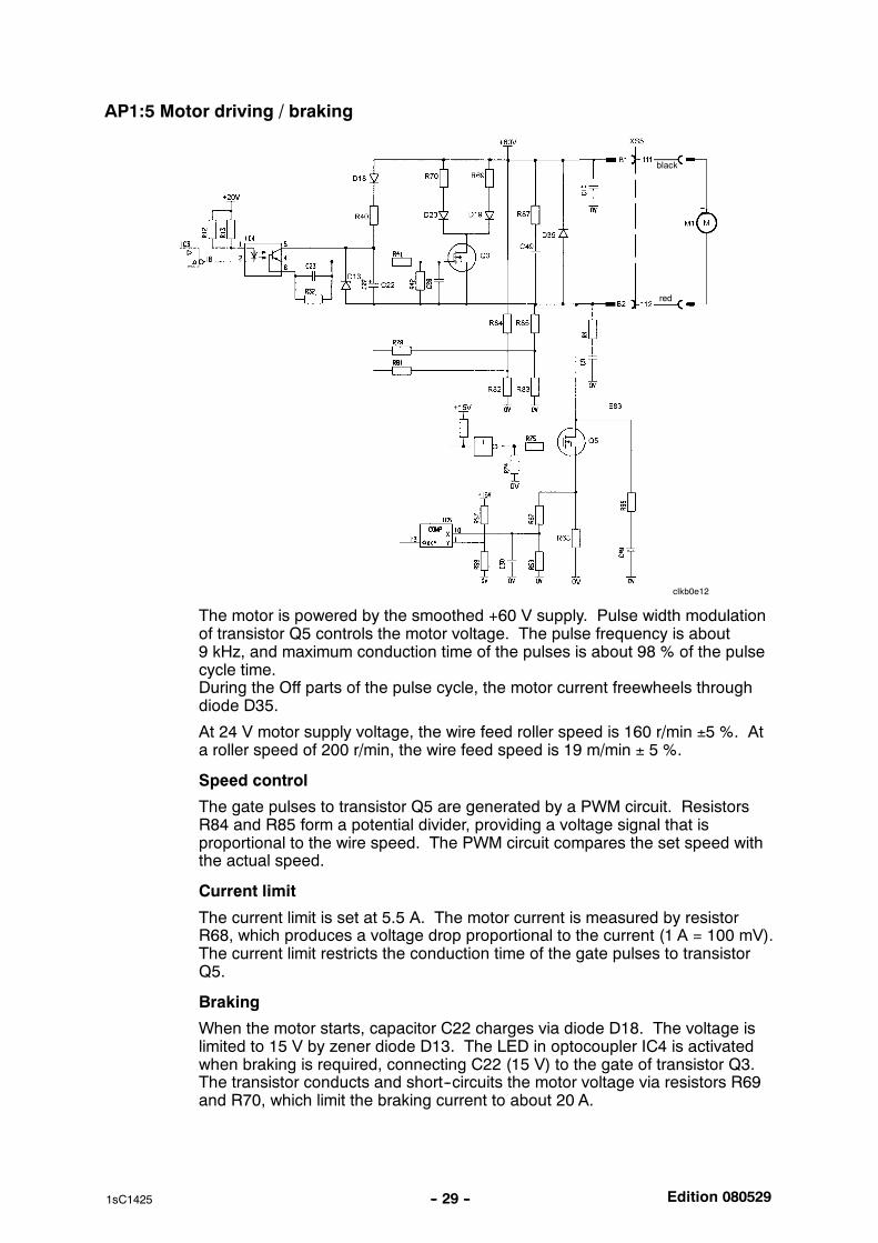
AP1:5 Motor driving / braking
clkb0e12
red
black
The motor is powered by the smoothed +60 V supply. Pulse width modulationof transistor Q5 controls the motor voltage. The pulse frequency is about9 kHz, and maximum conduction time of the pulses is about 98 % of the pulsecycle time.During the Off parts of the pulse cycle, the motor current freewheels throughdiode D35.
At 24 V motor supply voltage, the wire feed roller speed is 160 r/min ±5 %. Ata roller speed of 200 r/min, the wire feed speed is 19 m/min ± 5 %.
Speed control
The gate pulses to transistor Q5 are generated by a PWM circuit. ResistorsR84 and R85 form a potential divider, providing a voltage signal that isproportional to the wire speed. The PWM circuit compares the set speed withthe actual speed.
Current limit
The current limit is set at 5.5 A. The motor current is measured by resistorR68, which produces a voltage drop proportional to the current (1 A = 100 mV).The current limit restricts the conduction time of the gate pulses to transistorQ5.
Braking
When the motor starts, capacitor C22 charges via diode D18. The voltage islimited to 15 V by zener diode D13. The LED in optocoupler IC4 is activatedwhen braking is required, connecting C22 (15 V) to the gate of transistor Q3.The transistor conducts and short--circuits the motor voltage via resistors R69and R70, which limit the braking current to about 20 A.
Edition 080529-- 30 --1sC1425
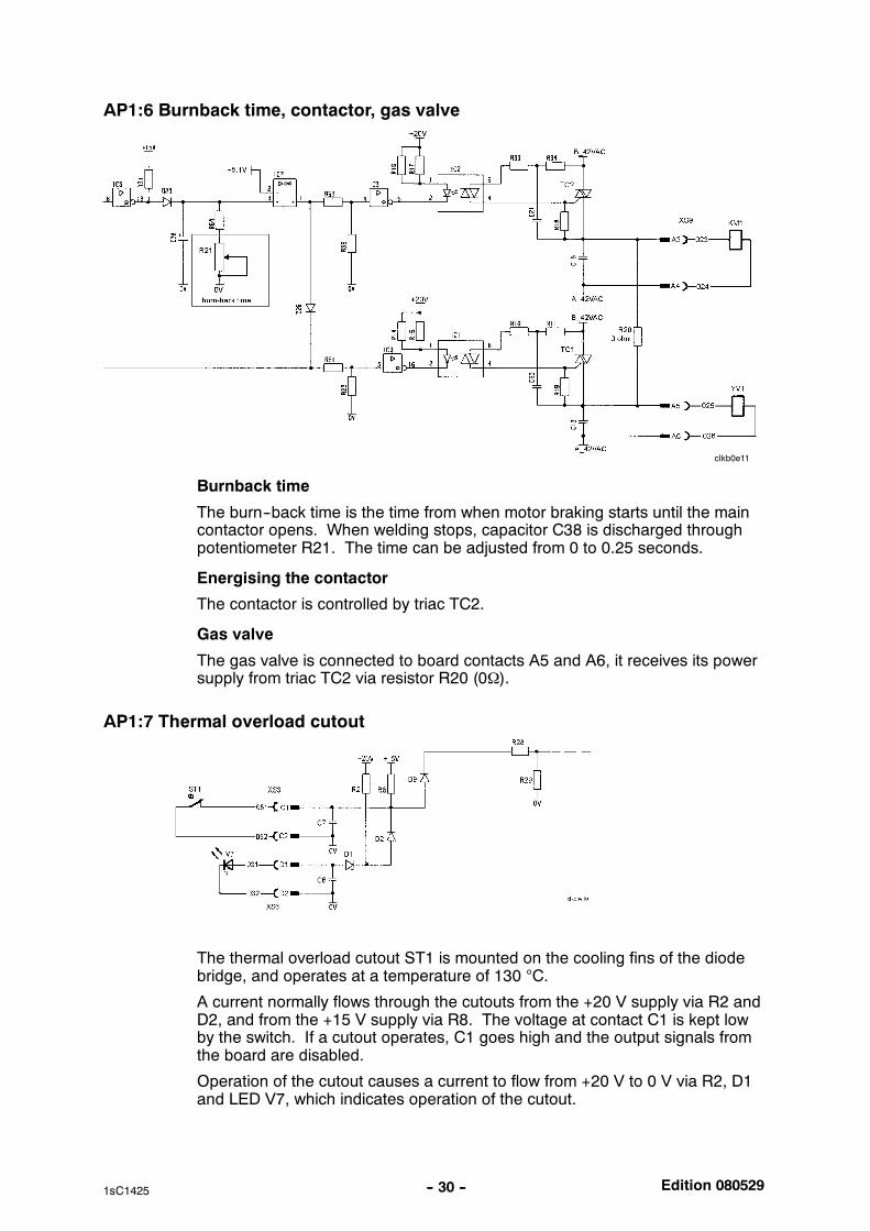
AP1:6 Burnback time, contactor, gas valve
clkb0e11
Burnback time
The burn--back time is the time from when motor braking starts until the maincontactor opens. When welding stops, capacitor C38 is discharged throughpotentiometer R21. The time can be adjusted from 0 to 0.25 seconds.
Energising the contactor
The contactor is controlled by triac TC2.
Gas valve
The gas valve is connected to board contacts A5 and A6, it receives its powersupply from triac TC2 via resistor R20 (0Ω).
AP1:7 Thermal overload cutout
The thermal overload cutout ST1 is mounted on the cooling fins of the diodebridge, and operates at a temperature of 130 °C.
A current normally flows through the cutouts from the +20 V supply via R2 andD2, and from the +15 V supply via R8. The voltage at contact C1 is kept lowby the switch. If a cutout operates, C1 goes high and the output signals fromthe board are disabled.
Operation of the cutout causes a current to flow from +20 V to 0 V via R2, D1and LED V7, which indicates operation of the cutout.
Edition 080529
clkb0e13
-- 31 --1sC1425
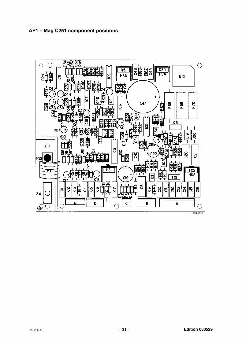
AP1 -- Mag C251 component positions

Edition 080529-- 32 --1sC1425
SERVICE INSTRUCTIONS
What is ESD?
A sudden transfer or discharge of static electricity from one object to another. ESD stands forElectrostatic Discharge.
How does ESD damage occur?
ESD can cause damage to sensitive electrical components, but is not dangerous to people.ESD damage occurs when an ungrounded person or object with a static charge comes intocontact with a component or assembly that is grounded. A rapid discharge can occur,causing damage. This damage can take the form of immediate failure, but it is more likelythat system performance will be affected and the component will fail prematurely.
How do we prevent ESD damage?
ESD damage can be prevented by awareness. If static electricity is prevented from buildingup on you or on anything at your work station, then there cannot be any static discharges.Nonconductive materials (e.g. fabrics), or insulators (e.g. plastics) generate and hold staticcharge, so you should not bring unnecessary nonconductive items into the work area.It is obviously difficult to avoid all such items, so various means are used to drain off anystatic discharge from persons to prevent the risk of ESD damage. This is done by simpledevices: wrist straps, connected to ground, and conductive shoes.
Work surfaces, carts and containers must be conductive and grounded, use only antistaticpackaging materials. Overall, handling of ESD--sensitive devices should be minimized toprevent damage.
WARNING !STATIC ELECTRICITY can damage circuitboards and electronic components. Observe precautions for handling electrostatic
sensitive devices.
Use proper static--proof bags and boxes.ESD
Thermal switch (thermostat) replacement procedure
1. Spare thermostat must be the same type as replaced one.
2. Spare thermostat should be mounted within radius of 10mm or less from brokenthermostat. If it’s possible and safe for transformer/inductor winding, broken thermostatmay be removed. Then the spare thermostat is to be mounted right in place of brokenone.
3. Spare thermostat should adjoin protected winding as tight as possible.
4. Spare thermostat must be secured with silicone glue of working temperature of 200oCor higher.
Edition 080529-- 33 --2sC1425
INSTRUCTIONS
This chapter is an extract from the instructions for Mig C141/151, Mag C171/C201/C251.
SAFETY
Users of ESAB welding equipment have the ultimate responsibility for ensuring that anyone whoworks on or near the equipment observes all the relevant safety precautions. Safety precautionsmust meet the requirements that apply to this type of welding equipment. The following recommen-dations should be observed in addition to the standard regulations that apply to the workplace.
All work must be carried out by trained personnel well--acquainted with the operation of the weldingequipment. Incorrect operation of the equipment may lead to hazardous situations which can resultin injury to the operator and damage to the equipment.
1. Anyone who uses the welding equipment must be familiar with: its operation location of emergency stops its function relevant safety precautions welding
2. The operator must ensure that: no unauthorised person is stationed within the working area of the equipment when it isstarted up.
no--one is unprotected when the arc is struck
3. The workplace must: be suitable for the purpose be free from draughts
4. Personal safety equipment Always wear recommended personal safety equipment, such as safety glasses, flame--proofclothing, safety gloves.
Do not wear loose--fitting items, such as scarves, bracelets, rings, etc., which could becometrapped or cause burns.
5. General precautions Make sure the return cable is connected securely. Work on high voltage equipment may only be carried out by a qualified electrician. Appropriate fire extinquishing equipment must be clearly marked and close at hand. Lubrication and maintenance must not be carried out on the equipment during operation.
WARNING!
Read and understand the instruction manualbefore installing or operating.
Edition 080529-- 34 --2sC1425
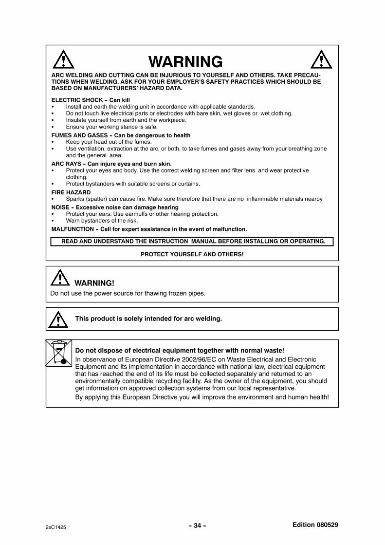
WARNING
READ AND UNDERSTAND THE INSTRUCTION MANUAL BEFORE INSTALLING OR OPERATING.
ARC WELDING AND CUTTING CAN BE INJURIOUS TO YOURSELF AND OTHERS. TAKE PRECAU-TIONS WHEN WELDING. ASK FOR YOUR EMPLOYER’S SAFETY PRACTICES WHICH SHOULD BEBASED ON MANUFACTURERS’ HAZARD DATA.
ELECTRIC SHOCK -- Can kill Install and earth the welding unit in accordance with applicable standards. Do not touch live electrical parts or electrodes with bare skin, wet gloves or wet clothing. Insulate yourself from earth and the workpiece. Ensure your working stance is safe.
FUMES AND GASES -- Can be dangerous to health Keep your head out of the fumes. Use ventilation, extraction at the arc, or both, to take fumes and gases away from your breathing zone
and the general area.
ARC RAYS -- Can injure eyes and burn skin. Protect your eyes and body. Use the correct welding screen and filter lens and wear protective
clothing. Protect bystanders with suitable screens or curtains.
FIRE HAZARD Sparks (spatter) can cause fire. Make sure therefore that there are no inflammable materials nearby.
NOISE -- Excessive noise can damage hearing Protect your ears. Use earmuffs or other hearing protection. Warn bystanders of the risk.
MALFUNCTION -- Call for expert assistance in the event of malfunction.
PROTECT YOURSELF AND OTHERS!
Do not use the power source for thawing frozen pipes.
WARNING!
This product is solely intended for arc welding.
Do not dispose of electrical equipment together with normal waste!In observance of European Directive 2002/96/EC on Waste Electrical and ElectronicEquipment and its implementation in accordance with national law, electrical equipmentthat has reached the end of its life must be collected separately and returned to anenvironmentally compatible recycling facility. As the owner of the equipment, you shouldget information on approved collection systems from our local representative.
By applying this European Directive you will improve the environment and human health!
Edition 080529-- 35 --2sC1425
INSTALLATION
The installation must be executed by a professional.
Note!Connect the power source to the electricity mains with a network impedance of (C141 -- 0,41; C151 -- N/A;C171 -- N/A; C201 -- 0,32; C251 -- 0,212) ohm or lower. If the network impedance is higher, there is a riskof flicker in the illuminators.
WARNING!This product is intended for industrial use. In a domestic environment this product may cause radiointerference. It is the user’s responsibility to take adequate precautions.
Placing
Position the welding power source such way that its cooling air inlets and outlets arenot obstructed.
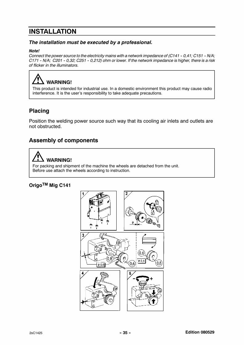
Assembly of components
For packing and shipment of the machine the wheels are detached from the unit.Before use attach the wheels according to instruction.
WARNING!
OrigoTM Mig C141
Edition 080529-- 36 --2sC1425
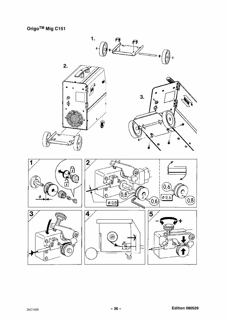
OrigoTM Mig C151
1.
3.
2.
Edition 080529-- 37 --2sC1425
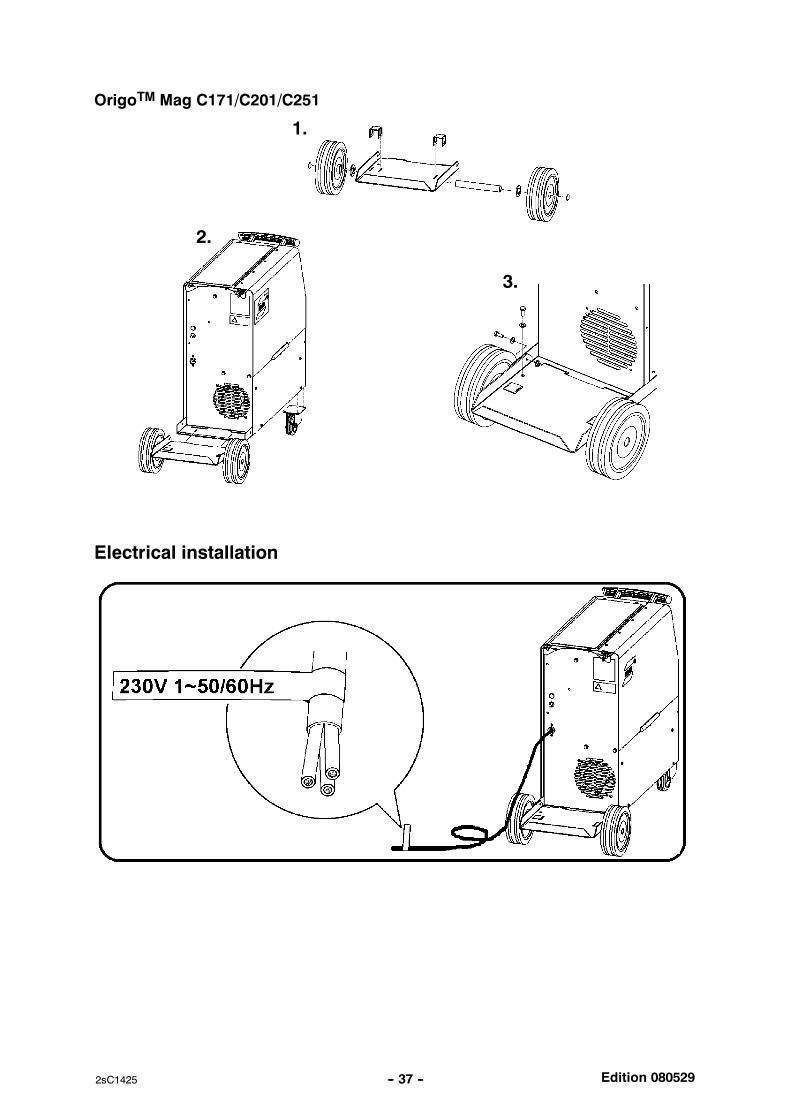
OrigoTM Mag C171/C201/C251
1.
3.
2.
Electrical installation
Edition 080529-- 38 --2sC1425
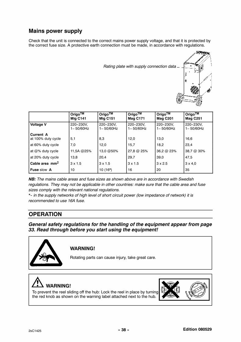
Mains power supply
Check that the unit is connected to the correct mains power supply voltage, and that it is protected bythe correct fuse size. A protective earth connection must be made, in accordance with regulations.
Rating plate with supply connection data
OrigoTMMig C141
OrigoTMMig C151
OrigoTMMag C171
OrigoTMMag C201
OrigoTMMag C251
Voltage V 220--230V,1∼ 50/60Hz
220--230V,1∼ 50/60Hz
220--230V,1∼ 50/60Hz
220--230V,1∼ 50/60Hz
220--230V,1∼ 50/60Hz
Current Aat 100% duty cycle 5,1 8,3 12,0 13,0 16,6
at 60% duty cycle 7,0 12,0 15,7 18,2 23,4
at @% duty cycle 11,5A @25% 13,0 @50% 27,8 @ 25% 36,2 @ 23% 38,7 @ 30%
at 20% duty cycle 13,8 20,4 29,7 39,0 47,5
Cable area mm2222 3 x 1.5 3 x 1.5 3 x 1.5 3 x 2.5 3 x 4,0
Fuse slow A 10 10 (16*) 16 20 35
NB: The mains cable areas and fuse sizes as shown above are in accordance with Swedish
regulations. They may not be applicable in other countries: make sure that the cable area and fuse
sizes comply with the relevant national regulations.
*-- in the supply networks of high level of short circuit power (low impedance of network) it is
recommended to use 16A fuse.
OPERATION
General safety regulations for the handling of the equipment appear from page33. Read through before you start using the equipment!
WARNING!
Rotating parts can cause injury, take great care.
To prevent the reel sliding off the hub: Lock the reel in place by turningthe red knob as shown on the warning label attached next to the hub.
WARNING!
Edition 080529-- 39 --2sC1425
WARNING -- TIPPING RISK!
There is a risk of tipping while transportation and operation, if the welding machine leansmore than 10o. In that case appropriate securing has to be provided !
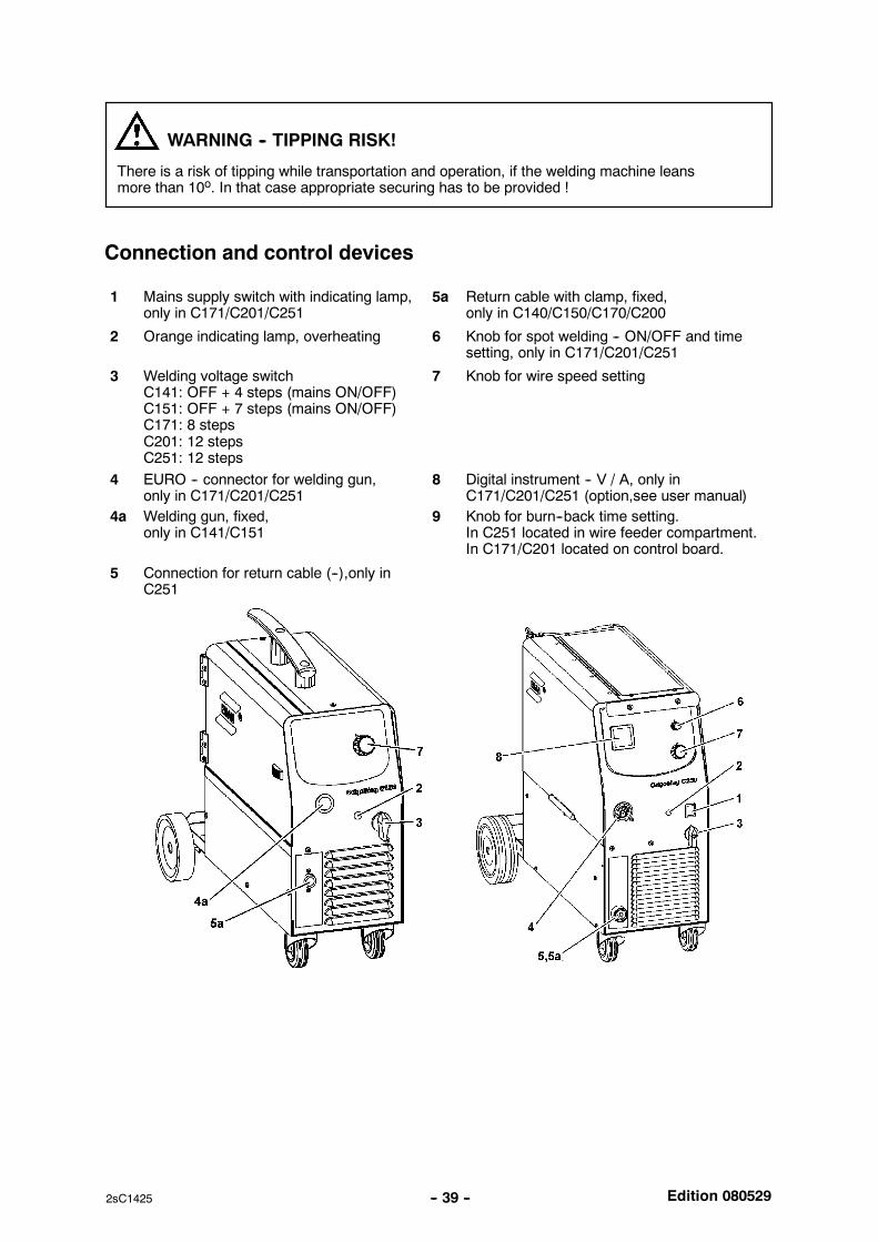
Connection and control devices
1 Mains supply switch with indicating lamp,only in C171/C201/C251
5a Return cable with clamp, fixed,only in C140/C150/C170/C200
2 Orange indicating lamp, overheating 6 Knob for spot welding -- ON/OFF and timesetting, only in C171/C201/C251
3 Welding voltage switchC141: OFF + 4 steps (mains ON/OFF)C151: OFF + 7 steps (mains ON/OFF)C171: 8 stepsC201: 12 stepsC251: 12 steps
7 Knob for wire speed setting
4 EURO -- connector for welding gun,only in C171/C201/C251
8 Digital instrument -- V / A, only inC171/C201/C251 (option,see user manual)
4a Welding gun, fixed,only in C141/C151
9 Knob for burn--back time setting.In C251 located in wire feeder compartment.In C171/C201 located on control board.
5 Connection for return cable (--),only inC251
Edition 080529-- 40 --2sC1425
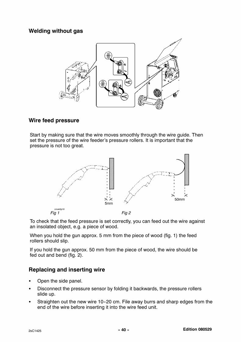
Welding without gas
Wire feed pressure
Start by making sure that the wire moves smoothly through the wire guide. Thenset the pressure of the wire feeder’s pressure rollers. It is important that thepressure is not too great.
Fig 1 Fig 2
To check that the feed pressure is set correctly, you can feed out the wire againstan insolated object, e.g. a piece of wood.
When you hold the gun approx. 5 mm from the piece of wood (fig. 1) the feedrollers should slip.
If you hold the gun approx. 50 mm from the piece of wood, the wire should befed out and bend (fig. 2).
Replacing and inserting wire
Open the side panel.
Disconnect the pressure sensor by folding it backwards, the pressure rollersslide up.
Straighten out the new wire 10--20 cm. File away burrs and sharp edges from theend of the wire before inserting it into the wire feed unit.
Edition 080529-- 41 --2sC1425
Make sure that the wire goes properly into the feed roller track and into the outletnozzle and the wire guide.
Secure the pressure sensor.
Close the side panel.
Overheating protection
When themachine is switched on with the mains switch [1] or [3] depending onmachinemodel, indicating lamp [1] is on and lamp [2] off -- the machine is ready to operate. If theinternal temperature becomes too high, the welding is interrupted and disabled. Thisstate is indicated by lighting of the orange indicating lamp [2] on the front of themachine.It resets automatically when the temperature has fallen.
MAINTENANCE
Regular maintenance is important for safe, reliable operation.
Note!All guarantee undertakings from the supplier cease to apply if the customer himselfattempts any work in the product during the guarantee period in order to rectify anyfaults.
Inspection and cleaning
Check regularly that the power source is free from dirt.
The power source should be regularly blown clean using dry compressed air at reducedpressure. More frequently in dirty environments. Otherwise the air inlet/outlet may be-come blocked and cause overheating.
Welding gun
Cleaning and replacement of the welding gun’s wear parts should take place atregular intervals in order to achieve trouble--free wire feed. Blow the wire guideclean regularly and clean the contact tip.
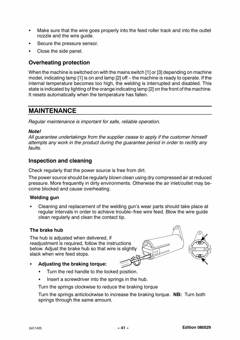
The brake hub
The hub is adjusted when delivered, ifreadjustment is required, follow the instructionsbelow. Adjust the brake hub so that wire is slightlyslack when wire feed stops.
Adjusting the braking torque:
Turn the red handle to the locked position.
Insert a screwdriver into the springs in the hub.
Turn the springs clockwise to reduce the braking torque
Turn the springs anticlockwise to increase the braking torque. NB: Turn bothsprings through the same amount.
Edition 080529-- 42 --2sC1425
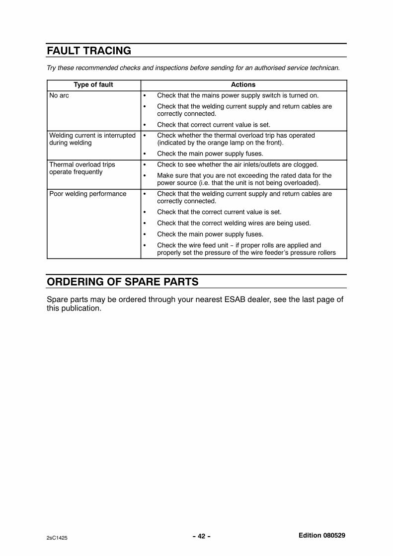
FAULT TRACING
Try these recommended checks and inspections before sending for an authorised service technican.
Type of fault Actions
No arc Check that the mains power supply switch is turned on.
Check that the welding current supply and return cables arecorrectly connected.
Check that correct current value is set.
Welding current is interruptedduring welding
Check whether the thermal overload trip has operated(indicated by the orange lamp on the front).
Check the main power supply fuses.
Thermal overload tripsoperate frequently
Check to see whether the air inlets/outlets are clogged.
Make sure that you are not exceeding the rated data for thepower source (i.e. that the unit is not being overloaded).
Poor welding performance Check that the welding current supply and return cables arecorrectly connected.
Check that the correct current value is set.
Check that the correct welding wires are being used.
Check the main power supply fuses.
Check the wire feed unit -- if proper rolls are applied andproperly set the pressure of the wire feeder’s pressure rollers
ORDERING OF SPARE PARTS
Spare parts may be ordered through your nearest ESAB dealer, see the last page ofthis publication.

-- 43 --notes
NOTES

-- 44 --notes
ESAB ABSE--695 81 LAXÅSWEDENPhone +46 584 81 000
www.esab.com
070514
ESAB subsidiaries and representative offices
EuropeAUSTRIAESAB Ges.m.b.HVienna--LiesingTel: +43 1 888 25 11Fax: +43 1 888 25 11 85
BELGIUMS.A. ESAB N.V.BrusselsTel: +32 2 745 11 00Fax: +32 2 745 11 28
THE CZECH REPUBLICESAB VAMBERK s.r.o.VamberkTel: +420 2 819 40 885Fax: +420 2 819 40 120
DENMARKAktieselskabet ESABHerlevTel: +45 36 30 01 11Fax: +45 36 30 40 03
FINLANDESAB OyHelsinkiTel: +358 9 547 761Fax: +358 9 547 77 71
FRANCEESAB France S.A.Cergy PontoiseTel: +33 1 30 75 55 00Fax: +33 1 30 75 55 24
GERMANYESAB GmbHSolingenTel: +49 212 298 0Fax: +49 212 298 218
GREAT BRITAINESAB Group (UK) LtdWaltham CrossTel: +44 1992 76 85 15Fax: +44 1992 71 58 03
ESAB Automation LtdAndoverTel: +44 1264 33 22 33Fax: +44 1264 33 20 74
HUNGARYESAB KftBudapestTel: +36 1 20 44 182Fax: +36 1 20 44 186
ITALYESAB Saldatura S.p.A.Mesero (Mi)Tel: +39 02 97 96 81Fax: +39 02 97 28 91 81
THE NETHERLANDSESAB Nederland B.V.AmersfoortTel: +31 33 422 35 55Fax: +31 33 422 35 44
NORWAYAS ESABLarvikTel: +47 33 12 10 00Fax: +47 33 11 52 03
POLANDESAB Sp.zo.o.KatowiceTel: +48 32 351 11 00Fax: +48 32 351 11 20
PORTUGALESAB LdaLisbonTel: +351 8 310 960Fax: +351 1 859 1277
SLOVAKIAESAB Slovakia s.r.o.BratislavaTel: +421 7 44 88 24 26Fax: +421 7 44 88 87 41
SPAINESAB Ibérica S.A.Alcalá de Henares (MADRID)Tel: +34 91 878 3600Fax: +34 91 802 3461
SWEDENESAB Sverige ABGothenburgTel: +46 31 50 95 00Fax: +46 31 50 92 22
ESAB international ABGothenburgTel: +46 31 50 90 00Fax: +46 31 50 93 60
SWITZERLANDESAB AGDietikonTel: +41 1 741 25 25Fax: +41 1 740 30 55
North and South AmericaARGENTINACONARCOBuenos AiresTel: +54 11 4 753 4039Fax: +54 11 4 753 6313
BRAZILESAB S.A.Contagem--MGTel: +55 31 2191 4333Fax: +55 31 2191 4440
CANADAESAB Group Canada Inc.Missisauga, OntarioTel: +1 905 670 02 20Fax: +1 905 670 48 79
MEXICOESAB Mexico S.A.MonterreyTel: +52 8 350 5959Fax: +52 8 350 7554
USAESAB Welding & Cutting ProductsFlorence, SCTel: +1 843 669 44 11Fax: +1 843 664 57 48
Asia/PacificCHINAShanghai ESAB A/PShanghaiTel: +86 21 5308 9922Fax: +86 21 6566 6622
INDIAESAB India LtdCalcuttaTel: +91 33 478 45 17Fax: +91 33 468 18 80
INDONESIAP.T. ESABindo PratamaJakartaTel: +62 21 460 0188Fax: +62 21 461 2929
JAPANESAB JapanTokyoTel: +81 3 5296 7371Fax: +81 3 5296 8080
MALAYSIAESAB (Malaysia) Snd BhdSelangorTel: +60 3 8027 9869Fax: +60 3 8027 4754
SINGAPOREESAB Asia/Pacific Pte LtdSingaporeTel: +65 6861 43 22Fax: +65 6861 31 95
SOUTH KOREAESAB SeAH CorporationKyungnamTel: +82 55 269 8170Fax: +82 55 289 8864
UNITED ARAB EMIRATESESAB Middle East FZEDubaiTel: +971 4 887 21 11Fax: +971 4 887 22 63
Representative officesBULGARIAESAB Representative OfficeSofiaTel/Fax: +359 2 974 42 88
EGYPTESAB EgyptDokki--CairoTel: +20 2 390 96 69Fax: +20 2 393 32 13
ROMANIAESAB Representative OfficeBucharestTel/Fax: +40 1 322 36 74
RUSSIALLC ESABMoscowTel: +7 095 543 9281Fax: +7 095 543 9280
LLC ESABSt PetersburgTel: +7 812 336 7080Fax: +7 812 336 7060
DistributorsFor addresses and phonenumbers to our distributors inother countries, please visit ourhome page
www.esab.com


