o .$:, ..?. ! ! 0 ,$ k ! 1- (!!9 b —- ,. t!!!!o w, !!!9 Y: MIL-c-19713A(sslPB) 30 December 1959 SUPERSEDING MIL-C-19’713(SBIPS) 29 January 1957 MILITfiY SPECIFICATION COOLERS, F~UID, AFTER AU& DIESEL ENGINS, NAVAL SkUPBOARD 1. SCOPE 1.1 -- This specfficatkm covers Dfessl engine after ntr cocders for Naval shipboard sPpllca- Uml. 1.2 Clnsslflcailcm. - lb coolers @@l bs of the foflowing clnsses, as spectfied (see 6. 1): Class 1- Submarfne applications. Class 2- Surface ships. Class 3- I.andlng craft snd smsll bat npplicntlon. 2. APPLICABLE DOCUMENTS 2.1 l%e followlng swcificattons, standards, drawings and publlcmlons, of the Issue In effect on date of Invltatton for bids, form a part of thfs Spectflcallan to the sxtenl spsclfled herein: SPECIFICATIONS FEDERAL O-G-93 - Gnlvantzing I&pnlr Compound. QQ-N-2SI - Nickel-CopXr-AllOy (Monel and R-Monci) Bars, Plates, Rods, Shests, Strips, W&e, Forgings, and Structuml and Spsclnl Shsped Ssctlons QQ-P-330 - Phosphor Bronze Bar% Plates, Rods, Sbssts, Strips, Flat Wire, and Structural and Special Shnpsd SectIons. QQ-S-741 - Steel Platss, Shnpes and Bars, Carbon, Slmctural. CC!_S-775 - Steel, Shest, Zinc-Coated. uU-P-271 - Paper, Wrapping, Waterproofed Krnft. PPP-B-5U1 - Boxes, Fibertmnrd, Wood-Clented. PPP-B-SOI - Boxes, Wood Cleated-P&mmod. PPP-B-S21 - Boxes, Wcc.d, NaUed md frock-Corner. MILITARY MIL-C-104 - Crates, Wood; Lumber and Plywood Sheaked, Nnlled and IkAted. ML-P-116 - l%ese!vatlon, Methods of. MIL-B-121 - Barrier Mnterffd, GrsnsepKwfed, Waterproofed, Flexible. ~L-c-132 - Crate, Wood, Open; Mnxlmum Capsclty 2, ~ Pounds. MIL-B-233 - Boxes, Repair Pnrts. JAN-P-735 - Primer, Prdnt, Zfnc-Chromate, Alkyd Type. MIL-B-857 - Bits, Nuts, md Studs. MIL-S-901 - shockproof Equipment, Class HI (High-hnpnct), Shlpbonrd Appllcallon, Tests for. ML-D-953 - Drawings, ProductIon, Proceduro for Procurement of. MIL-B-994 - Brass, Naval: Ffnds, Sheets, Str!p!3, Wire, Shapes, Forgfngs and Ffai Pro@ucts (Flat Wire, Strip, Sheet, Bar md Plate). r FSc 4420 [ Downloaded from http://www.everyspec.com
Transcript
o.$:,..?.!!
0,$
k
!1-
(!!9
b
—-,.
t!!!!ow,
!!!9Y:
MIL-c-19713A(sslPB)30 December 1959SUPERSEDINGMIL-C-19’713(SBIPS)29 January 1957
MILITfiY SPECIFICATION
COOLERS, F~UID, AFTER AU& DIESEL ENGINS,
NAVAL SkUPBOARD
1. SCOPE
1.1 -- This specfficatkm covers Dfessl engine after ntr cocders for Naval shipboard sPpllca-Uml.
1.2 Clnsslflcailcm. - lb coolers @@l bs of the foflowing clnsses, as spectfied (see 6. 1):
Class 1- Submarfne applications.Class 2- Surface ships.Class 3- I.andlng craft snd smsll bat npplicntlon.
2. APPLICABLE DOCUMENTS
2.1 l%e followlng swcificattons, standards, drawings and publlcmlons, of the Issue In effect on dateof Invltatton for bids, form a part of thfs Spectflcallan to the sxtenl spsclfled herein:
Sheet, Bar, and Plate).MIL-P-15742-PbJgs, Plastic (Heat-Exchanger-Tube).MfL-E-1580S - Expander, Tube, Condenser and Heat Exch-&gerS.MJL-A-15939 -Aluminum Bronze Bars, Plates, Rods, Sheets, Strips, ForgfngS,
and Structural and Special Shaped Sections.MfL-T-16420 -Tube, 70-30 and90-10Copper-Nlckel Alloy, Seamiess and Welded.MIL-B-16541 - Bronze, Valve: Castings.MIL-M-16576- Metal, Gun: Cast fngs.MIL-A-17357 -Aluminum Alloy 5154 (A543)Plates and Sheets.MIL-A-17472 -Asbestos Sheet Compressed (Packfng Material),MIL-C-17516 - Copper-Silicon Alloy Bars, Plates, Rods, Sheets, Strips, Flat
Wire, Wire, Forgings, and Structural wid Special Shaped Sections,MJL-P-17545 -Primer, Faint, Shipboard, Alkyd - Red Lead Type, Formula No. 116.MfL-C-17728 - Control and Drive Assembly, Tube Expander, Automatic.MfL-Z-178’71 -Zinc-Coating (Hot-Dip-Galvanizing),MIL-A-18001 -Anodes, Corrosion Preventive, Zinc: Plate, Slab, Disc and Rod
Shaped.ML-A-19070 -Aluminum Alloy Plates and Sheets, 5086 (K1S6).MIL-P-19415 - Plugs, Zinc Anode Retaining, Heat Exchanger Cathodic ProtectIon.MIL-A-19521 -Anodes, Corrosion Retentive, Zinc; Design of and fnsta.lla:lon in
Shipboard Condensers and Heat Exchangers.MIL-F-20342 -Flanges, Pipe, Bronze (Silver Brazing).MfL-T-20166 -Tubes, Red Brass, Seamless, 6,000 PSI Maximum Pressure.MIL-G-2161O -Gaskets, Heat Exchanger, Various Cross Section Ring, Synthetic
Rubber.
NAVY DEPARTMENTGeneral Specifications for Inspection of Material
STAND.&S
MuJTARYMIL-STD-129 - Marking for Shipment and Storage.MIL-STD-167 - Mechanical Vibrations of Shipboard Equipment,MIL-STD-271 - Nondestructive Testtng Requirements for Metals.MfL-STD-276 - Welding and Allied Processes for Machinery for Ships of the
United States Navy.
● !
.
..
Downloaded from http://www.everyspec.com
MIL-C-19713A(SBI.PS)
DRAWINGS
BURSAU OF SHIFSB-104 - Flt:fngs, Pipe, Composltlon, Flanged; Pressures lGO P.S. I. and Below.B-214 - ROOt Connectlans for Attaching Ptplng.S10- 13S5875 - Plugs, Zknc, and Adapters for H-1 Exchangers.50~-S48Z3 -841338- FIUlngs, Silver ANDYBrnzlng, for 011, Water, Gas or Oxygen.
PUBLICATIONS
BURSAU OF SHlP3NAVSHIB 250-537-1 and -2- ~dlograph!c Standards for Bronze
Cnstlng3.
(Cc@es of specfflcations, standards, drawfngs, and publlcailons regulred by contractors In connec-tion with speclflc procurement functions should be obtrdned from the procurkng activity or as directed bythe contracting officer. )
2.2 Otier cmbllcatiorw. - The foUowfng documenti form a part of this Speclftcathm to the extentspec!fled herein. Unless othervkse Indlcnted, the It!sue in effect on dnte of fnvltatlon for bids sl!nll‘apply.
AMSRICAN SCCIETY OF MECHANICAL ENGfNEERSBoiler and Pressure Vessel Code, Section ~ - Ruleo for Construction of Unfired
Pressure Vessels.
(ApPllcntlOn for copies should be addressed to the Amerlcnn Society of Mechanical Engfneers,39 West 391JI Slreet, New York 18, N. Y. )
NATIONAL BURSAU OF STANDARJX3Handbook H2S - Screw Thread .!.tnndllrds for Federal .%+ces.
(Application for copies should be addreswwd to the Superintendent of Documents, Govemmenl PrlntfngOffice, Washington 25, D. C. )
OFFICIAL CLASSIFICATION COMMIT1’EEUniform Frelghl Ckasslflcation Rules.
(APPlkation for c0Pb3S should be addressed to the Off Ic Id Clns.slflcation Committee, 1 Park Avenueat 33rd Street, New York 16, N. Y.)
3. REQUIRSMENT3
3.1 Pmrmoduct!on model. - When cpecffled (me 6. 1), a preproduction model shall be furnfshed andtested In nccordsnce wtth thb requlrementO of 4.2.
3.2 Materials. -
3. 2.1 fn the des!gn of coolem for ml: water service; care shall be taken to avoid combinations ofmalerfnls which may prcduce delrlmen!ml gnlvanlc action.
3. 2.2 Threaded cmrts. - Threaded parw shall conform to Handbook H28. Des!gns shall permit theuse of standnrd wrenches lhrOughOuL Cap screwsahrdl not ka used. Stud sizes and number at studs forzfnc cover bolt clrdes droll be comparable to those requ! red for bolt circle lnymut for coolant side flange%The use of bolts less than 7/16 Inch diameter for pressure jolnta shnfl be avoided. The Unified threadform 1s preferred for threaded parts. When usfng this form, the setting end of studs shall be aclass 3A-3B fit, and the class 2A-2B flt ohnll be used as the generaf working fit.
3
Downloaded from http://www.everyspec.com
3. 2.3 Weldlng shall be in accordance with Standard MIL-STD-278. When brazing alloys containingnickel, such as composition 70-30 or 90-10 copper-nickel, grade IU silver-base-brazing-alloy con-forming to Specification MfL-S-l 5395 shall be used.
3.3 General desbm. - ●3. 3.1 Space and welqht. - In all designs, space and weight shall be held to a minimum consistent
with strength and rellabfl[ty of the coolers.
3. 3.2 Inclinina. pitchinq, and mllinq. - The design cd all coolers shall be such that they will per-form satisfactorily under the followtng conditions of operation with the ship:
(a) Pernmmmtly inclined from the normal posltlon in the fore and aft plane, up or down:Surface ship ----------------------------------------- 5 degrees.Submarhes ------------------------------------------ 30 degrees.
~) Permanently incllned 10 either S!de of the vertical:Surface ship ----------------------------------------- IS devee~,Submarines ------------------------------------------ 15 degrees.
(c) RDlling from the vertical to either side:Surface ship ----------------------------------------- ~~ degree,,Submarkes - ---------------------------------------- 60 degrees.
(d) Pltchfng up or down fmm the normal h.rlzontal plane:Surface ship ----------------------------------------- lo degrae~Submarines ------------------------------------------ 10 degrees.
3. 3.3 Shock resistance. -
3. 3.3.1 Shock test of tie complete cooler assembly is required. If engine mounted, shock testrequirement for tie engfne shall govern. Shock tests shall be performed as specified in SpeclfiL?a-tlon MIL-S-901 with tie followlng modifications:
(a) Under the test procedure for medium weight equipment, the first blow in each groupshall be applied using the standard (horizontal) mounting adapter; the second blowin each group shall be applied with the adapters holding it at a 45-degree angle fromthe horizontal in the direction of the units least transverse strength.
3.3.3.1, 1 Waiver of shock tesllng will be considered for units if they are of similar design, con-struction, weight and materials to units which have successfully passed the tests spec~led in Speclfica-tlon MIL-S-901.
3. 3.3.2 Shock resistance des[un. -
3. 3.3,2,1 Unless otherwise specified In the contract or order, bolts designed to be stressed Inshear shall be fnstafled in holes “o greater than the following sizes:
Nominal bolt dtameter Maximum diameter of hole(inch) (Inch) i
3/4 and smaller Nomtnal bolt diameter +1/32Larger than 3/4 Nominal bolt diameter +1/16
3.3.3, 2.2 Units :hat are rigidly supported shall not be attached to two structures which can deflect.
relative to each other under shock lcadinas.
3. 3.3.2.3 Shock mounts shall not be used withont prior approval of the bureau or agency comxrned. ●4
Downloaded from http://www.everyspec.com
MIL-C-19713A(SHITJ3)
3. 3.3.3 For guidance tn dweloplng a shock resistance design see appendix to this specification.
3.3.3.4 Vlbratlon. - Each cooler shall be designed to withstand type I vlbratlon of Stand-ard MIL-STD-1 6’/ U separately mounted and n comblnatlan of types I and If vfbration of Stnnd-ard ML-STD-167 U engine mounted.
3.3.4 Coolers maybe s!ngle or ❑ulli-pnssonthecoollng side.
3.3.5 Unless otherwise speciflad (see 6. 1), the mnxtmum permissible pressure drdp at design mn-dltio!!s shall te 6 P.s. L for the coofnnt water and 1 inch mercury (Hg. ) for Lhe air side.
3.3.6 Them coolers shall be class 1 for submarine appllcatlons, class 2 for surface ship appllca-Uons, and class 3 for fandlng craft and small Lmat applicntlans, unles9 othenvlse specffled (see 6. 1).
3.3.7 Inlet and outlet comect!ons for sea water, shaff be flanged unless hose connections ares+mcif[ed (see 6. 1). UnIess othem’fse spectfled In the contract or order, flanges shall be type PR, Plnln,250 pounds, 1/4 td 12 Inch Stze, inclusive, ofSpocfflcatlon MfL-F-20042, with cast nozzles conformingto the dimensions shown on Drnwlng B-104. For fabricated nozzles, b! lleu oftieplafn, 250_pound flangeof Specification MIL-F-2JXJ42, sllp-on flanges ofIhesame dlmmslons in regard to diameter, mlckness,and drflllng will be acceptable. For higher pressures, the flange design sludl be as specffled (see S. 1).
3.3.8 All coolers shall b provhied with vent and drain connection so located as to permit com-plete venltng cmd drnlnfng of the mofant. Mlnfmum size for vents nnd dmfns shall be 1/8 fnch Imn pipesize (i. P.s. ). Such connections shall be made by one of the foflowtng methods, as applicable:
(a) Where space will permk, the vent or drnfn connection shall consist ofa pipe tappedhole fitted WIUIan oversize adaptor, p!ece 1 of Dmwfng 5000-S4S23-841 338. Ahexngonal wrenching shoulder may lx! provided an such adaptors and 1s considereda deslmble feature. The use of thfs adnptor will permit the shipyard either to pipeup fd the comectlon in an approved manner md without the necessity of applyfngbrazing heat to the caolor (that fs, by bmzlng td the adaptor), or toreplace theadaptor w1!JI a pipe plug when connecting piping Is not required.
(b) Where space wI1l not permit use of the above methdd, the vent or drain cdnnectlonshall conform to figure 6 of Dmwfng B-214, with a short length oftubing welded orbrazed fnto the socket. (The Prdvls!on ofthis nipple fs to elfmfnate the need for theshipbuilder 10 apply heat to the cooler proper with consequent risk of warpfng ordamage to gaskets. ) Such nipples shall conform to Drawfng B-214, havfng a wa.flthlclmess not less than that of the corresponding size of extra strong brass PIPWM an exception to the nonferrous materials called for by Drawtng B-214, wheresuch IIIPPICS are pravfded on the salt water side of a cooler Lhey 5halJ be of copper-nlckel alloy canfarmlng to composition 70-30 of Specfflcnllon MfL-T-16420 forclass 1 codlers, of copper-nickel alloy conforming to composition 90-10 of Speci-fication MJL-T-1 6420 for class 2 ceders, &nd of red bmss conform lng to SpecI -ficntlon MIL-T-2016S for cfmm 3 codlers.
(c) For large coders vent or drafn connections conformb!g to figure 2 or 3 of Draw-ing B-21 4 will be ncceptablo as an alternate to tha method specif!ed in (a) above.
3.3.9 Connections for pressure gages shall be provided at Inlets and outlets of coolant sides whenspecified (see 6. 1). Such ConnectIons shall conform to 3.3.8. V/heroaddltlomd connections are can-sldered desirable for occasional usc fu testing, pipe tapped holes fitted with pipe plugs may be used.
3.3.10 Hydrostatic pressure. - Coolers shall be designed to withstand the hydrdstntlc pressure testspecff ied In 4.5.4.
3.3.11 Zinc m-c.iectors. - The coollng water side of coolers shall be fitted with corrosion preventiveanodes in accordance WIUISpecific.ntlon MIL-A-19521.
5
Downloaded from http://www.everyspec.com
MIL-C-19713A(SHIFS)
!
●3.3.12 Coollnq water flow. - In the design of cooUng water spaces and connections, a smooth flow
path shaU be provided in order to m hdmize erosion-corrosion attack. Sharp corners and projectingedges shall be avoided. Zincs and internal f i:tings shallbe arranged So that bIteIferenCe with the water flOWwiU be minimized. Cooling” water velocities at design point shall not exceed 6.5 feel per second throughthe islet fl!dnge ~d 4.5 feet per second through the tubes.
3.3.13 Coolhm surface. - The amount of cooling surface installed in all coolers shall be based onthe service specified (see 6. 1), applying a 10 percent fouiing factor to the heat transfer coefficient forclean tubes. Tbe design coollng waler iniet temperature shall be taken as 85” Fahrenheit (F. ) unlessotherwise specified (see 6. 1).
3. 3.13.1 Tube SUPwrtS. -
3. 3.13.1.1 For coolers mounted on the engine, minimum distance between tube support platesshall be 12 inches. For separately mounted coolers minimum distance between support plates shall be18 fnches. M!mimum thickness for support plates shall be 1/4 inch.
3.3.14 Summrts, - AU coolers shall be provided with adequate supports for securing to a foundation.When required by the conditions of service, provision shall be made in the design of the supports to pm-vlde for expansion or contraction of tie shell. Cooler support shall be independent of any attached piping,and If arranged for support of the cooler fmm a vertical structure, shaU be so desiqr.ed that bolts Imshear do not constitute the primary means of support. Coolers shaU not be supported by plates or brac-kets in such manner that the primary means of support is obtained from the ixdts securing the shell endflmge-tube sheet-water box flange joints.
3.3, 15 Flat gaskets. - Compressed asbestos gaskets shall be 1/16 or 1/32 inch thick. Cloth insertedrubber gaskets shall be 1/16 inch thick. Coolers shall be so designed that an adequate gasket width isprovided under water box partitions. In coolers having an equivalent shell diameter of 12 inches or more,this gasket width sbaU be not less than 5/16 Inch.
3.3, 16 O-rina qaske;s, - Where a test pressure above 300 pounds per square Inch gage (p. s, i. g. ) isspecif[ed, recessed flat gaskets or O-ring gaskets conform lng to Specification MIL-G-21 610 shall befurnished.
3.3, 17 Selecllon of packina materhls. - fn selection of packing materials full consideration shall begiven to temperature resistance requirements.
3.4 Drawings shall be furnished In accordance with Specification MIL-D-963.
3. 4.1 T!mes of drawings. - In lleu of the drawing types listed In Standard MfL-STD-7, the foUowingtypes are required:
3. 4.1.1 Outffne drawinq. - An exterml arrangement drawing shall show all necessary external vfewsOf the cooler assembly, shall Include all external dimensions necessary for reproduction on ship,s orengine’s machinery arrangement drawing, for guidance of the engine manufacturer or shipyard in designingthe foundation structure for tie assembly, for Installation thereof, and for connection of the assembly tothe exterml piping. The drawing shall show the space required for removal and replacement of the tubesor tube bundle, removal of waterboxes, access opening covers, zinc adodes, location of lifling lugs oreyebolts provided for handltng the unit cm’Its components and size of openings therein.
3. 4.1.2 Assembly drawinu. - A drawing showing complete longikadlnti and transverse cross -sec-tional views cd the cooler assembly shall also. show the relationship of all parts, arrangement of tubes inthe heat exchanger component, method of tube end expansion or packing, baffles, support plates and weld-ing of adjacent parts. Liberal use of enlarged views or sections shall be made. If necessary, s“b-assem -bly drawing conforming to the above may be furnished for individual compments of the unit, The draw-~9(s) s~ll be such that a thOrOugh understanding of the design and construction may be obtained w[tioutreference to related detail drawings.
i
I
●
,
.
00 0
Downloaded from http://www.everyspec.com
fLfL-c-19713A(EFfIR3)
3. 4.1.2.1 The assembly drawtng shall contain a complete 11s1ofmalerlals showtng names and cor-respandlng Identffylng numlmrs and matsrlals of all parts used In the construction of tie cooler. Theldentlfyfng part shalf also be shown adJacent to the part depicted In the various views with arrows pofntsdto the parts.
3. 4.1.2.2 The assembly drawing shaff lndlcnte that the ztnc anodes pmvlded In the heal exchangercomply with Specificntlon MtL-A-19521.
3. 4.1.2.3 Defnll drawing of major parts such as shells, lube 5heets, Suwmrt plates,baffles,supportfeet, waterbaxes, and the like, shall be completely and accurately dimensioned w!th flnfshes, weldlngsymbols and Identifying part numbers Indicated, as required for manufacture.
3.4. 1.3 Shlo’s drawbm.- One drawing shall ka a ship’s drawing. It shall ke tltfed “Drawfng LfsGperformance Data, and Ontoard Rep31r Parts List for Diesel Engine After-Air Cmler” (designation ofcooler by mtiel number, or by sfze and elms, to be entered to complete the title). A Ilst of mater!alsis not rsqufmd for this drnwfng. The SMP’S dmwfngs shall be fncluded In the first submfsslan of worktngdmwlngs.
3. 41.3.1 The dmwtng Ifst tnbulntlon sl!nll fnclude the followfng columns:
(a) Dmwlng title.(b) Manufacturer’s dmwfng number.(c) Bureau or agency drawLng number.(d) Revlslan symbol.
Ttds Ifst shall tnclude all master dmwfngs which comprlae the given design. The mvlslon symbol Mlu!nnshall be kept UP to date to the Nme of manufacture so that it will flnnllyfndlcate the latest mvfstan of eachdmwfng appllcnble to the equipment as buflt.
3.41.3.2 The performance dam tabulation shall include the followfng:
(a)M
(c)(d)(e)(f)(9)m)(1)W(k)(1)
Idsnttficatltm of cmled nnd ccollnfd mediums.Flow mte of coaled and mollng ❑~dlums (gallons per mfnute (g. p. m. ); cubic
feet per minute (c. f.m. )).Inlet temperature of cooled and coollng mediums (“F.).outlet tarnpemture of cooled and cmlfig mediums (“F.).Pressure drops of cooled and coollng mediums through cmler (p.s. L L (Inches ffg. ).Velocities of cooled and cmling mediums at Inlet connection (feet per sscond).Velceilles of cooled and cwlfng mediums through tubes and shell (feet per second).Number of passes of cooled and coolLng mediums through cooler.Working pressure of moled and cool~g mediums (p.s. 1.g. ).Test pressure, tube s!de (p. 0.1. g. ).Test pressure, spce between doublo tube sheets (P. s. Lg. ), when appllcnble. a~@rlmmIc me~ L9MP0rabMe difference (“F.).
1When ccalers are for semlce on submnrtnes, In Ileu ofINIentry fn the tabufatlon oppasltaUds headfng, the .sPce should be left blank. Eeslde Ihe tnbulntfon use an arrow leadfngIn to lndlcnte this blnnk SPCR, and at the tall of the arrow add a note “FOR TUBE SIDET=T ~ SEE N~E — ON _ DWG _ BUSfifR3 NR TESTDATA, _“.
—rThis note Is to be completed when the speclffc tnformntion &mmes
nvallablefmm the buildlng yard.‘When ceders ars fm service an submarines, In lieu of m entry fn the tabufatlon oppcelte
thfs hmdlng, the space should be left blank. Beside the tabulation use m arrow lsadlngfn to fndlcate th13 blank sp!lce, and at tho trill of LIWJarrow add a nolo “FOR T=T PR.2S-SURE FOR SPACE BETWEEN DOUBLE TUBE SHEETS SEE NOTE _ ON _ DWG_BUEHfFS NR , TEST DATA ‘‘. ThlQ note Is to be completed when fnforma -:Ion becomes available fmm the bull&~rd.
7
Downloaded from http://www.everyspec.com
1
MIL-C-19713A(SHIPS)
(m) Heat transfer rates for both service and clean tube conditions (British thermalunits (B. t. u. ) per hour per square foot per “F. logarithmic mean temperaturedifference).
(n) Effective coollng surface (square feet).(o) Heat transfer capacity at design point (B. t. u per hour).
3. 4.1.3.3 The onboard repair parts list shall be beaded ‘‘ONBOARD REPAIR PARTS LIST -Quantities FOR ONE SET” and shaU itemize the repair parts and tools (see 3, 8). This tabulailon shallfnclude tie following columns:
(a) Piece rmmber (maybe omitted when parts are detailed on nmno-detafl type draw fngs).(h) Name cd piece.(c) Quantity.(d) Manufacturer’s drawing number.(e) Manufacturer’s service part number. 1(f) Weight. (Each entry In this column shall be the product of the number required and
the unit Weight of the part. The total of this column shall Lndlcate the weight of theonboard set. )
‘ The m antiacturervs serv[ce as a constant number, assigned by the manufacturer, whichis the infallible identLflcation ,of a part wherever used. When it Is the practice to assignpart numbers to all pieces, these shall be recorded on the proper drawings. Where acomplete part numbering system fs no: 1“ use, the manufacturer shall assign servicepart numbers to each cooler and to each part cd sub-assembly which [n his judgmentmay require replacement during the Iffe of the unit. Such numbers shall then berecorded on the proper drawings.
3.4.1,3, 4 The ship’s drawing shall include notes indicating the contract or order number, the appli-cation (service) of the unit, the number of coolers per ship and per unit Of parent equipment, and tie dryand wet weights of the cooler. The following examples Ulustrate the type of notes required:
(a) Bureau of Ships Contract NObs-1234 with ABC Engine Companfi ABC Engine Companypurchase order 5678 on EFG Cooler Mfg. Co.
(h) Service: After air cceling for propulsion Diesel engfne.(c) Eight coolers per ship, one cooler per engine, or 12 coolers furnished as stock
material.(d) Dry weight of cmler _ pounds; weight of cooler_ po~ds,
3. 4.1.3.5 Tme ship’s drawing shall also include a view of the ldentffim.tion plate with all data enteredexcept date of manufacture, serial number, and tube side m=imum test pressure for submarine saltwater applications, For these applications use an arrow leading in to indicate the blank space where tubeside maximum test pressure would have been entered, with the notation “TUBE SIDE MAXIMUM TESTPF.ESSURE NOT TO BE STAMPED ON IDENTIFICATION PIATE, >placed at tie tall of the arrow. Thisview shall be enlarged when necessary to !nsure that data entries will meet lettertng size requirements ofSpecfflcation MIL-D-9SS.
3.4. 1.3.6 Above the title block of this drawing there shall be entered the designations of the applica-ble ships.
3.5 Paintinq. - Coolers shall be painted as specified hereinafter:
(a) External and Internal nonferrous surfaces of water boxes, tubes, and tube sheet?,shall not be painted.
(b) Sleel surfaces shall be thoroughly cleaned and coated with one coat of pretreatment\n accordance with formula No, 117 of Specification f5L-c-153213 and one coat ofprimer in accordance with formula No. 84/47 of Specification JAN-P-735 orformula No. 116 of Specification MfL-P-17545,
.
●8 ● ’
Downloaded from http://www.everyspec.com
MJL-C-19713A(SHIPS)
S. 6 Identiflcatlon plates .- Xdenttflcatlon plata~ nhall ba provided In accordance with SpecUlca-tlm MIL-P-15024, and shall include tie followtng:
(a) Name cd unit.(b) Mrimdacturer’? service P3rt numtmr.(c) Stock number.(d) Name of mnmdacprer.(e) Contract number. (The pmcurlng actlvlty’u contmct or purchase order
number shall bs entered In this opce. )(f)Blink space for Government bwpector’o stamp.(g) Date of manufacture.(h) Serlnl numter.(1) Maxim.m test pressure, tube olde.(1) Blank space for “unit” number. s (’I’IIIcI8P3CE wI1l be used for numberfng for
shipboard reference purpmes when roqulred, lho ~tnmplng to Lw done by shlP-ynrd. )
(k) Dedgnation “U.S.”.
1A11ow 17 ~ilC.SS.: Uttflze width of Pfnte to allow mnxlmum numbar of swces.‘Allow 4 spces.
Working pressura entries QI!AIInot appear on ldrmtUlcntIon pbltml
3.’7 Construction. -
S. 7.1 Materfalm - The mnterlaM used tn commructlon ofcoolers shrill be as follow:
3. 7.1.1 The materials ~hown In tables 1, II and 111and an cpectfied herefnafkr drill lm used an thetasls for design. These materfnls shall be usc+d In We conowuctlon of the coolers, except tit the manu-facturer shall have tbe option of Substltutlng commercial mnlerlnl lmvfng equal or better phys!cni oadchcmlcal properties than the ma:er!ti speclfled h Fedeml or MUltnrY spectficatlons. ff tbe mnrmdac-turer exercises the above option, ho ahnll Include two cpclflc.ntlon columns In the Ilst ofmaterials on hfsdrawings; cme column shall be wed for tho speclfled Fedeml or Milltnry opectflcntlons, and the othershall show the commercfnl Spectflcntlon number for the aubstltuted material. Notes shall th?n appear onthe drnwlng fstntlng that:
(a) The design IS based on tie Federal or MUUary OpeclflcUtlOn nmterfnls.@) The IINIterhk Ifsted tn the commerclnf Ctpoclflcntlan column have phyolcal and
chemical properties which are equnl to or batter than the opecffied Federnf orMllitnry spectflcatlon and may be substituted by the manufacturer.
It shall be the resprmolbUlly ofthamwmfacturer to sntfnfy the Government tnswctor thnt Uds 1s the case.Any prts for wh!ch mnter!nls are not specffled shnlf be of the quailty best suited for the purpose Mended.
9
Downloaded from http://www.everyspec.com
I MIL-C-19713A(SHIPS)
3.7.1, 1.1 Class 1 cooler materials shall be as specified in table I.
‘After complete fabrication of shell, the shell shall be hot dip galvm[zed in ac~Ord~~ewith Speclfiiation MIL-2-17871.
‘After complete fabrication of the shell, a z[nc coaifnq conforming to SpecUication O-G-93or its equivalent as approved by the bmeau or agency concerned shall bo applted wherenecessary.
3Form Lobe in accordance with Specification MIL-B-657.%ee 3.3.17,
%3Zinc support plugs for submarines shall conform to Drawing 810-1365675.
10
●✌✌
●
☛I
.
.
●
●
Downloaded from http://www.everyspec.com
@.!:.
o“$..
*
,
4!!9..! .,.
,
69
@
MIL-C-19713A(SHIPS)
S. 7. 1.1.2 Class 2 cmler materials shall be as specUled bI table II.
1After complete fabrication of shell, the shell shall be hot dlppsd galvnnised In accordanceWIIJ Speclflcatlon MIL-Z-17671.
‘After complete fnbrlcntion of the shell, a zinc cmtlng conforming to Specification O-G-93,or its equlvnlenl as approved by the bureau or agency concerned shall be applled wherenecessary.
a Form to be In ncmrdrmce with Speclflcntlon MIL-B-657.4See 3. S. 17.
’11
Downloaded from http://www.everyspec.com
MIL-C-19713A(SHIPS)
3. 7.1.1.3 Class 3 ccoler materfals shall be as specified In table III.
Table III - Class 3 cooler materials.
Part Material : SpecU’icatiOn :.:
: Shell
: Water boxes
Tube sheets: Tubes: Fins for tubes: Gland rings, ff used
lAfter complete fabrlcatim of shell, tie shell shall be hot dip galvanized In accordancewith Sr)ecificatlon MIL-Z -17871.
‘After c&nplete fabrication cd the Shell, a ZI°C co?.tlng conforming to Specification O-G-93or its e-q”ivalent as approved by the bureau or agency concerned shall be applied wherenecessary.
3Form to be tn accordance W!OISpecification kuL-B-657.%ee 3. 3. 17.
12
●I
\
●4
●
☛
●
Downloaded from http://www.everyspec.com
c!?::..
(!!9-’1’5.
c!!!?!,,
@9,..
(!!9. .
MIL-C-19713A(3HIP3)
3. 7.2 Coolers ahnll have atrnlght or U-bent plaln or flmed tubes with sea water circulated throughthe tubes.
3.7.3 Coolers droll be de$dgned to allow for exprumton of the tube bundle and shell.
3.7.4 Oouble tubn nhcot mnntructlon. - When apeclfled (see 6. 1), the coolers shall be pmvlded withtwo tutm tieew at each end. A ~pace between the two sheets approxlmntely 1/2 Inch wide shall be Pro-vided by me of a ~paclng ring or by machlnbtg one or Imth ~hee~. The joint between the sheem or thejoints between oheets and ring maybe welded or brazed, or may Lw a bolted de~lgn usfng restrained flatgaskctc! or O-ring gmketn (tee 3.3. 16). The space between the lube sheem ohall be vented and drrdned toatmosphere. The tubes shall be expanded Into each tube sheet m provided in 3.7.5. i, and care sh=dl betaken IJut the dlscontinul:y in tube surface caused by the axpa.olon Is kept to a minimum. After expansionof the tubes, the s~clfled tube aide hydrwtntlc test presc.ure hall be applled to the spaces between tietwo tube sheets at each end, and there shall be no leaknge under this pressure.
3. 7.5 Tubes nnd tube !3heeb% - Coolers sbnll h prwlded with lubes of 5/8 Inch outside diameter,O. 049 fnch (number 18 Birmingham r.lre gage (BWG)) wall th!cknes~, 3/8 Inch outside dfameter,0.049 Inch (number 18 BWG) wall thicknesw or 1/4 fnch outside dhmeter 0.025 fncb (number 20 BWG)wall thickness, as specified (see 6. 1). Tubes droll bo provided wtth external nonferrom fins.
3.7. 5.1 Tubes of all cmler~ shrdl be .zxWded into the tuba 8heets at both ends. The expansion shallbe done by means of a bdm expnder fn accordance with 3pecIflcation MfL-E-16809 and shall k governedby an a.tomntlc tube expander control In accordance WIIJISpecMlcatlon MIL-C-17728. The mtnimum deplhcd expamlon of tubes ~hnll be as speclf[ed In table IV. When preosure or other des!gn considerationsrequire thicker tube sheeb than speclfled In table V, the depth of the tube expansion may b increasedover that !3hOVM[n table IV, but a dlntnnce of 1/8 Inch from lho freer face of the outm tube sheet shall bethe lbnlt of axp.mslon. Where m fnner (supplementary) tube ohe.at Is used expansion nhall not extendcloser than to wlthtn 1/8 fnch of either face.
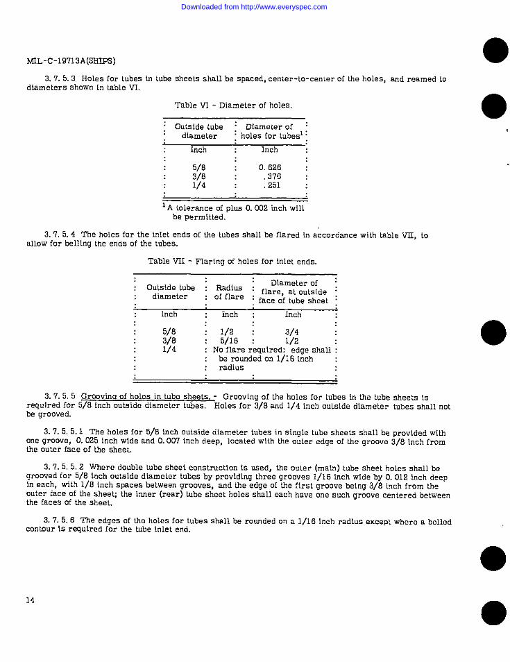
3. 7.5.5 Grcrovfna of holes in tube sheets. - Grooving of the holes for tubes in the kube sheets k.required for 5/8 inch outside diameter tubes, Holes for 3/6 and 114 inch outside diameter tubes shall notbe grooved.
3. 7.5.5.1 The holes for 5/6 inch mdslde diameter tubes in single tube sheets shall be provided withone groove, O. 035 inch wide and O.007 inch deep, located with the outer edge of the groove 3/8 inch fromthe outer face of the sheet,
3, 7. 5.5.2 Where double tube sheet construction is used, the outer (main) tube sheet holes shall begrooved for 5/8 inch outside diameter tubes by providing three grooves 1/16 fnch wide by O. 012 inch deepIn each, with 1/8 inch spaces between grooves, and the edge of the first groove being 3/8 inch from theouter face of the sheet; the inner (rear) tube sheet holes shall each have one such groove centered betweenthe faces of the sheet.
3. 7.5.6 The edges of the holes for tubes shall be rounded on a 1/16 Inch radius except where a boiledcontour 1s required for the tube inlet end,
14
●I
\
●
I
●
●
Downloaded from http://www.everyspec.com
ML-C -19713A(SHIPS)
3.7.5.7 The fnlet enis of 5/8 or 3/8 fnch outside diameter tubes shall be expanded and belled md theends shall Lben be ffnlshed flush wfth the face of the tuba sheet. Inlet ends of 1/4 fnch outside dfametertubes shall not be belled, but after expanskm ~hnll bo ffnbzhed flush wiUI the face of the tube sheet. In nocase shall the ends oftubes be below the faceofthetubesheets.Dlschnrge ends oftubes shall not prO-trude mom than 1/16 Inch beyond the face of the tube sheet.
3.7.6 Water boxes. - In order to absorb the entrmce velocities which may produce emslon oftubeends by Impingement attack, the water box depti measured normal to the tube sheet simdl be not less thanone-half the mean diameter uf the tube sheet area exposed to the flaw ofthecoollng waterIntothetubes.For cylfndrlcrdcoolers havfng an fnslde shell dfameter “D” the water box head depth shall be not lessthan 0.50 “D” for single pass coolers, 0.354 “D” for two pass coolers and 0.25 “D” for four passcoolers.
3.7.7 The waler Inlet comect!on to coolers shall be as nearly as possible normal to the tube sheet.shell connections shnlf be located to give counterflow hetwecn the coollng and tie cmled mediums as faras psslble. Coollng water flow In multlpns.$ coolers shall pass horkzonmlly or vertlcalfy upward betweenpasses, never downward. Venl holes shall be pmvlded [n the water Lmx Psrt!tlons.
3. 7.7.1 Water box deslmh-
3.7.7.1.1 Water boxes ~hnll conform to Ihe requirements! of We ASME Cwfe, SectIon VIII andaddenda thereto.HemIspherlcnl heads are preferred. Both cnm md fabricated inter boxes are accepta-ble.
3. 7.7.1.2 For calcufntlng the strength of welded joints, weld efflclencles shnfl be In accorcbmcewith Stnn&rd b?JL-ST D-278.
3.7.7. 1.3 If operatfng preosure dictates that a fnbricaled water box be cfnssff!ed as an AZ classpressure vessel under Standard MIL-STD-27S, all welded comectlons 2 Inches nominal iron pipesizeend over shnlf be full penetmtlon welded.
3.7. 7.1.3.1 For submarines, unless othorwlse speclfledh thecontractor order, cast watertieswhich will be subjected to submergence presoure shall be 100 P3rcent rndlographed. Ca9tfngs wfthnomlnaf wall thickness of1/2 Inch or less shall meet clnss 1 requirements of Publlc8-tion NAVSffJRi 2S0-537-1 orNAVSHIFS 250-527-2 md Umse wlti nomlmd wall thickness ofGver 1/2 inchshall meet class 2 requirements of L%bllcatlcm NAVSHIPS 250-527-1 or NAvSHfFS 250-537-2, = appUca-ble. In addltlon, machlm?d surfaces cd castings for this service shall be 100 percent Uquid Wnetranttested in accordmce wllh Standard MIL-STD-271 using type 111or type fv fluorescent penetrant. D2fectsshall not exceed 0.050 inch fn depth or O. 100 Inch in length.
3.7. 7.1.4 Water box Lmlllnu ro.aulrementa. - Boltlng for securing the water box to the tube sheetshall be nlz.ed so that the preslress necessary to mafntaln a tight joint under the specffied hydrostatic testpressure will not exceml 25 percent of the yield strength ofIhebolt materlttl based on 0.2 percent offsetes specffled M tie appllcnble mnterlnf specfflcntlon. When mfdffng up the water Lw./tube sheet joint, atorque wrench set so 8s not to exceed the above stress, shafl be used.
@
@
15
Downloaded from http://www.everyspec.com
MfL-c-19713A(sfiIPs)
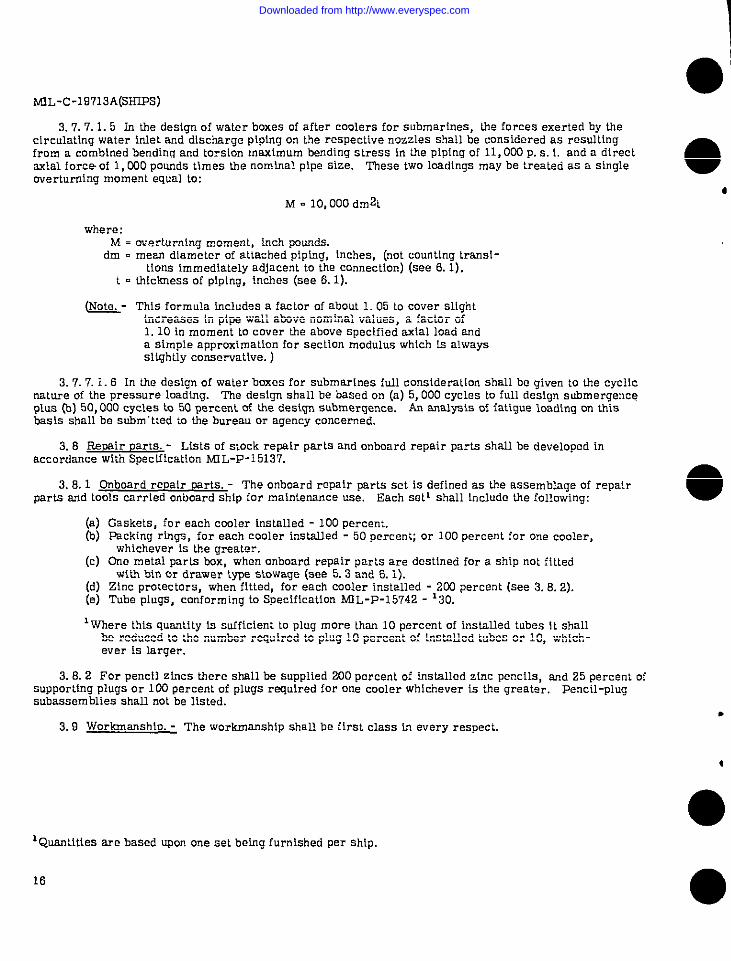
3. 7.7.1.5 in the design of water boxes of after coolers for submarines, the forces exerted by thecirculating wa:er inlet and discharge piping on the respective nozzles shall be considered as resuftlngfrom a combined bending and torsion maximum bending stress in the piping of 11, OCQP. s. L and a directaxial force of 1, CQOpounds llmes the nominal pipe size. These two loadings may be treated as a single ●overturning moment equal to:
dM -10,000 dm2t
where:M = overturning moment, inch pounds.
dm . mean diameter of attached piping, inches, (“et counting trans[-tlons immediately adjacent to the connection) (see 6. 1).
t = thickness of piping, inches (see 6. 1).
b- This fOrmula ~cludes a f@Or of abOut 1.05 LOCOVEFslightincreases In pipe wall above nomfnal values, a factor of1.10 in moment to cover the above specified axial load anda simple approximation for section modulus which 1s alwaysslightly conservative. )
3. 7.7.1.6 In tie design of water boxes for submarines full consideration shall be given to the cyclicnature of the pressure loadlng. The design shall be based on (a) 5, 000 cycles to fuLl design submergenceplus (b) 50,000 cycles to 50 percent of the design submergence. An analysis of fatigue loading on thisbask shall be subm “tted to tie bureau or agency concerned.
3.8 Repair park. .- Lists of stock repair parts and onboard repair parts shall be developed inaccordance with Specfflcation MI L-P-l 5137.
3. 8.1 Onboard repair mrts. - The onboard repair parts set is defined as the assemblage of repairparts and tools carried onboard ship for maintemnce use. Each setl shall fnclude the following:
(a) Gaskets, for each cooler inst811ed -100 percent.(b) Packing rings, for each cooler lnsta.lled -50 percent; or 100 percent for one cooler,
whichever is the greater.(c) One metal parts box, when onboard repair parts are destined for a ship not fitted
with bin or drawer ;~e stowage (see 5.3 and 6. 1).(d) Zinc protectors, when fitted, for each cooler installed -200 percent (see 3.6. 2).(e) Tube plugs, conforming to Specfflcatlon NEL-P-15742 -’30.
1where this quantity @, sufficient to plug more than 10 percent of installed tubes 1: shallbe reduced to the number required to plug 10 percent of installed Lubes or 10, which-ever is larger.
3. 8.2 For pencil zfncs there shall be supplied 200 percent of Insblled zinc pencils, and 25 perce”l ofsupporting plugs or 100 percent of plugs required for one cooler whichever is the greater. Pencil-plugsubassemblies shall not be listed.
3, 9 Workmanship. - The workmanship shall be first class ~ every respect.
1Quantities are based upon one sel being furnished per Ship,
16 ●
Downloaded from http://www.everyspec.com
Og...
(!!!9i%“:
4!9&
-.
#
MIL-C-19713A(2RW?J
4. QUALITY ASSURANCE PROVISIONS
41 Unless otherwise speclfled herein the supplier Is responsible for the performance cd all lnspec-t!an requirements prior to submission for Government Inspection cd acceptance. Qcept as otherwtsespecified, the supplier may utlllze his own facilities or my comtnerclal laboratory ncceplable Lo lheGovernment. InspectIon remrd9 of the examinations and tests shall be kept complete and avatlable to theGovernment as specified[n the contractor order.
4.2 precroductlon tests. - Pmpmductlon tests when spectf led (see 6. 1), shall mnslst ofthetestsspecified In 4.5 and shall be conducted at a laboratory satisfactory to IAe Bureau cd Ships.
4.3 pmducilan lnsoectlon. - Prcduc;ion Inspection shall mnstst oftbe-tnatlan and test spectfiedin 4.4 and 4.5.4 When specified b! the conlmct or order, the bureau or agency concerned may requireIll shock tests cd representative pmdmtion coolers. Where other spedflcatlons form a part af thisspeclflcatlon, sampllng, e%nmlra.tion and tests shalf be conducted as specified therein.
44 FXuntnntlon. - Each cmler shall be ex.nmlned by the Government bmpector to deb?rmtne mn-formancetoapproved pmductlcm drawings (dlmens!ons, tolerances, material and finish).
45-
45.1 Performance test. - A performance test shnfl be conducted to determine compllnnce withperformance mqulrements. This test shall Include accurate measurements ofcocdnnt and cmled mediumflows, pressure drops, and heat dlsslpawd at or corrected to operating conditions.
4. 5.2 Shock test. - The prepmduction model shall k class HI shock tested In accordance with Spec!-flcation Ml L-S-901.
4. 5.3 Vibration test. - A vibrat[on test shatl be conducted tn accordance with S!zmdard MIL-STD-167.
45.4 Hydrcetallc oressum test. - Unless otherwke specIf!ed, each cooler shall be gfven thefollowfng hydrostatic t!#3:z
Test pressure
Cmlant side ----------------------------------------- 100 p.s. 1. g.Space between double tube sheets (U furnished)----------Same as coolant side.
4.6 InspectIon orccedures. - For Naval purchues, the general tnspectlon procedures shall be inaccordance wtfJI General Specillcntlcms for Inspection of Matertal.
5. PREPARATION FOR DELIVERY
5.1 Preservation and packaqfnq (see 6. l). -
5.1.1 LevelA--
5. 1.1.1 Coolers cd nonferrous cons; ruct!on slmll & packaged In accordance with method IfI of Specl-ficntion MfL-P-l 16. Opentngs shall be sealed WIUI cnps, plugs or barrier materkl mnforming to Specifl -cntion MIL-B-121 secured tn place wfth tape.
5. 1.1.2 preservative t~e P-2 ofSpeclflcntlon MIL-P-116 shall be coated on ferrous surfaces whichnormally operate In oil.
lin tie case of the salt water side of a cooler doslgned for submarine Service, the hydrostatic test shrillbe mnducted in the presence oftheGovernment Ins&ctor.
17
Downloaded from http://www.everyspec.com
MIL-C-19713A(SHIFS)
5. 1.2 Level C.- Coolers shall be preserved and packaged in accordance with the manufacturer’scommercial practice. Openings shall be sealed to proh~blt the entrance of foreign matter.
5.2 Packina (see 6. l), -
5. 2.1 Level A.- Coolers, packaged as specified, shall be packed [n wood cleated plywood or nailedwood boxes or sheathed crates conforming to Specification PPP-B-601 (overseas type), PPP-B-621(class 2), or MIL-C-104, as appllable. The gross weight of wood or wood cleated boxes shall notexceed 200 cmunds unless the weiaht of a single cooler exceeds this weight. Wcud cleated plywood androlled wood-boxes shall be used f& gross w~ights not exceeding 500 po~ds. The boxes shall be modifiedby the addition of skids in accordance wititheapplicable box specification and the coolers bolted throughthe skids. When the gross weight of the unit exceeds 5@3pounds, the cooler shall be packed in a sheathedcrate.Anchorfng, blocking, bracing and cushioning shall be in accordance withtheappendix toSpecffl-ca~lon MIL-C-1 04.
5. 2.1.1 Wa;eivmofinu, - Equipment bolted to the base of a wood or wood cleated box shall beshrouded within the box with barrier material conforming to Specification UU-P-271. Shroudfng shall beapplied at least two-thirds of the way down in a manner 10 prevent tie formation of water pockets and topermit free circulation of air. AU sharp projections which would tend to tear the shroud shall be paddedor covered with a suitable cushioning material.
5. 2.2 Level B.- Cwlers, packaged as specified, shall be packed in wood-cleated fiberboard, wood-cleakd plywood, nafled wood tmxes or crates conforming to Specifications PPP-B- 591, PPP-B -601(domestic tvoe). PPP-B-621 [class 1). MIL-C-104. MfL-C-3774 or MIL-c-132. The uross weiaht of. . . .,, , ,.—vmod and w’.md cleated Lmxes shall no~’exceed 200 p“ounds unless the weight of a single iiem exce;ds thiswe]ght. Boxes shall be modified for gross weights over 203 pounds by the addition of skids In accordancewith tie amdic’able box specification and the cooler shall be bolted tbrouah the base and skfds. Coolerspacked in ‘&sheathed crates shall be shrouded as specified in Specfflcad& MfL-C -132 and appendixthereto. Anchoring, bkackfng, hractng and cushioning shall be in accordance with the appendh to Speci-fication MIL-C-104.
5. 2.3 Level C.- Cmlers, packaged as specified, shall be packsd to insure carrier acceptance atthe lowest rate and safe delivery at desllnatlon. Containers shall comply with Uniform Freight Classifi-cation Rules or regulations of other carriers as applicable to the mode of transportation.
5.3 &board repair Darts ad tools. - Onbcard repair parls and tools shall be cleaned, preservedand packaged in accordance with Specification fvftL-P-116. Onboard repair parts and tools shatl bepackaged one item per unit package unless used in sets or In quantities greater than one. where onboardrepair parts and tools are destined for a ship that is not fitted with bin or drawer type stowage (see 6. 1),the onboard repa[r parts and tools shall be packed in type M metal boxes conforml”g to Speclflca-tion MTL-B-233 and shall be over packed in shipping containers conforming to Specification PPP-B-621,or MIL-C -132. Where onboard repair parts and tools are destined for a ship that is fitted wit.k bin ordrawer t~e stowage (see 6. 1), onboard repair parts shall be packed in shipping containers Specffled bI5, 2.1 or 5. 2.2 and shall be subject to the weight limitations therein.
5, 4 hfarkinu.- In addition to any special marking required by the contract or order, interiorpackages and shipping containers shall be marked In accordance with Standard MIL-STD-129 and require-ments of the applicable container specification or appendix thereto. Equipment serial number shall bemarked cm one face of the shipping container.
6. NOTES
6.1 Orderhm data. - Procurement documents should specify the following:
(a)b)(c)(d)
Title, number, and date of this specification.ClaSs and service of cooler (see 1.2 and 3.3, 6).Identification of fluid to be cooled.Fate offlowof fluid to be ccmled, CFM at S. T. P
●
●✌✌
✌
18
Downloaded from http://www.everyspec.com
bnL-c-19713A(2HIPS)
(e) Inlet temperature of fluid to be cooled, “F.(f) Cutlet temperature of fluld to be cooled, “F.; or rate ofheatexchange, B. t. u. /hr.(g) IdenUflcatlon of cmla.nL(h) nte Of ffOWof coolmt, U estnbllshed, g. p. m.({) Inlet temperature of coolant, U otier than 85-F. (me 3.3. 13).~) Allowable design point pressure drops ofrespective ccoler sides, P.S.L inchesHg. ,
U other than speclfled In 3.3.5.(k) Whether coolers are for Subnmrlne, mwfaco ship, Lnndlng craft or small boat, appll-
catlan (see 3.3.6, 3.7. 1).(.4) Whether hose connectlon9 are required (SW 3.3. 7).(m) Type cd tlmged connectlon9, If other than as specified in 3.3.7.
b) %=2 ?s% 3.3.9).e cnnnect!ons are requf red al IG101and oullel of cmfant and ceded
(o) Whether double tube sheets at each end are rqulred (see 3.7. 4).(P) @@lde dlnmeter oftubes(see3.7’.5).(q)Hydrostntlc test pressure on tube side, P.9.L g.U other than as speclfled In 4.5.4.(r) Whetheronbasrd repair parts sew are req.lred (see 3. 8).(s) SelectIon of appllcnble levels of preservation, packagfng and packing (see 5.1 and 5. 2).(t] Whether or not the uhips for wfIich equfpment Is destined are fitted with b!n or drawer
tne ~twge (see 3.8.1 md 5. 3).(u) Xfships are fitted for bln or drawer type stowage, whether onbomd rep31r pnrtn nnd
tools shoufd ~ packed for level A or B (see 5. 3).(v) whether preproductlon tests are required (see 3. I and 4. 2).(w) Mean dlnmeter of attached plplng and thickness ofplping<oco 3.7.7.1. 5).
6.2 Strainer recommendation. - As n matter of bdormntton It should be noted that the use ofstrainers In salt water coolant Systems 1s recommended for coolers dng 3/S Inch or 1/4 Inch .nds!dediameter tubes.
-- When Government drawings, speclflcatlons, or other data areused for any purpcse otherlhnnInconnection with n deflnkely related Gmernment procurement operntlon, tie United Stntes Gover-nment thereby Incurs no reqmns[billty nor any obllgnllon whatsoever and Ihe facthat Uw Government mayhave formulated, furnished, or In any WY supplled lhe aatd drawfngo, speclf!callons, or other data IS notto be regarded by Impllcatlon or otherwise 89 In any manner Ilcenslng the holder or any other person orcorporation, or conveying my rights or permission to manufacture, use, or sell My patented Inventtonthat may M any way be related thereto.
Preparing actlvlty:Navy - Bureau of Sh[ps(Project 4420-0017Sh)
t!!!?
@
19
Downloaded from http://www.everyspec.com
MfL-c-19713A(sBIPs)
APPENDIx
10. This appendix k. Intended to guide the manufacturer in developing shockproof units,
10.1 General reaulrements far shockcnmafness. - Coolers shall be designed to withstand shock dueLo firing of the ship’s own armanent and nonconlact underwater explosions of near-miss aerial tmmbs,torpedoes, and mines. The ccolers shall be designed to resist shock as specified by curves A, B, and Cof figure 1. Shockmmmts shall not be used unless bureau or agency approval of the mount and Its pro-posed application 1s obtained. .For submarine applications, use curve A for both vertical and athwart-ships accelerations.
10.2 Generai desi w Information. - It fs important that all components be designed to withstand tieshock design shown by curves A, B, and C, cd figure 1 without failure or permanent deformation of thebase, holding down bolts ad footing.
10.3 In no case shall apiece of equipment be rigidly supported from more than one plane.
10.4 Shock design nmnbers specified by curves A, B, and C, Of figurel shall be applied at thepoirltsof attachment to the hull structure.
10.5 Bolts designed to be stressed in shear shall be inslalled in holes Witha minimum of clearance,?.s experience indicates that large clearances allow Impacting and subsequent failure.
10.6 W?mretwo or more components preinstalled onacommon rigid subbase, the feet adhoidtng-down bolts as well as the subbase shall bedeslgned foranacceleration based on the total weight of tieassembly.