97
Mahr GmbH · Carl-Mahr-Straße 1 · D-37073 Göttingen · Telefon +49 551 7073-0 · Fax +49 551 71021 Betriebsanleitung Operating Instructions Millimar C 1208 /C 1216
Mahr GmbH · Carl-Mahr-Straße 1 · D-37073 Göttingen · Telefon +49 551 7073-0 · Fax +49 551 71021
BetriebsanleitungOperating Instructions
Millimar C 1208 /C 1216
1Mahr GmbH, Millimar C1208/C1216
Dear valued customer,
Congratulations on choosing a product by Mahr GmbH. We kindly request that you follow the instructions below in order to ensure the long-term precision of your measuring instrument.
We operate a policy of continuous improve-ment and are constantly developing our prod-ucts, especially with regard to renaming of type designations. It is possible therefore that there may be slight differences between the text and illustrations in this document and the measuring instrument in your possession. We reserve the right to make changes to the design and scope of supply, the right to undertake further technical developments, and all rights relating to transla-tion of this documentation.
© by Mahr GmbH, Göttingen
The following symbols are used in these operat-ing instructions:
General information.
Important information. Failure to follow instructions marked with this symbol can cause inaccurate results and lead to equipment damage.
i
Permitted Uses
The MarCheck is used to calculate, process and display deviations in dimension and form record-ed by instruments in the MarShaft and Linear product lines by Mahr GmbH. The MarCheck is primarily intended for use with MarShaft MAN shaft measuring instruments as well as Linear 100 and Linear 800ff measuring instruments.
Manual shaft measuring instruments by the Helios can also be used with the MarCheck.
The operating, maintenance and repair in-formation specified in these operating in-structions and the operating instructions for the measuring station components must be observed.
i
2 Mahr GmbH, Millimar C1208/C1216
Disposal
Electronic devices, including accessories and used batteries (rechargeable and disposable), must not be disposed of as regular garbage, since they contain high-value materials that can be recycled and reused. European Directive 2002/96/EG (WEEE) requires that electrical and electronic devices must be collected separately to unsorted municipal waste so that they may be subsequently reprocessed. The crossed-out garbage can symbol indicates that separate collection is necessary. Mahr GmbH carries out the redemption and disposal of its electrical and electronic products in accordance with legal requirements. Please contact your local service representative.
Mahr GmbHCarl-Mahr-Straße 1D-37073 GöttingenGermany
Mahr GmbH is registered in Germany with the Elektro-Altgeräte-Register (EAR, 'national register for used electrical appliances') under WEEE Reg. No. DE 56624193.
Voided warranty
Service that is due to viruses that were introduced via a network connection or other data carrier, are generally excluded from the warranty services.
Storage temperatures below –10 °C or above +50 °C and relative humidity levels above 85 % will invalidate the warranty for the instrument.

3Mahr GmbH, Millimar C1208/C1216
Safety InstructionsThis instrument complies with the relevant safety regulations. It was dispatched from our production facility in good condition and perfect working order. However, failure to follow the instructions given below can cause personal injury or death.
1. Before you connect up and use the equipment for the first time, read the ac-companying documentation. Follow the safety precautions detailed in the op-erating instructions.
2. Keep the documentation close to the equipment ready for quick reference.
3. Follow safety precautions, accident prevention regulations and internal com-pany instructions. You should request further information from your company safety officer.
4. Before you connect up the equipment, check the local supply voltage to make sure that it is within the working range of the AC adapter (100 V - 240 V, 50 Hz - 60 Hz). If they do not match, the instrument may not be connected under any circumstances!
5. The instrument may only be connected to a grounded power socket which complies with the regulations of the local power supply company. This also applies to any extension cables used.
6. Only use original, intact AC adapters.
7. When connecting inductive probes make sure that the plugs are firmly screwed onto the connection sockets.
8. When connecting pneumatic probes make sure that the compressed air is con-nected properly.
9. Do not drop the instrument and make sure it is positioned securely.
10. Do not operate the instrument in areas where there is a risk of explosion and do not expose it to direct sunlight!
11. Do not clean the membrane keypad with cleaners that contain solvents.
12. Before opening the housing, disconnect the power supply.
13. The gages with which the Millimar is used are subject to gage monitoring. For this reason, gage monitoring performed by the user or Mahr Service must
ensure adherence to the specified error limits.

4 Mahr GmbH, Millimar C1208/C1216
5Mahr GmbH, Millimar C1208/C1216
Order No. Last Modification Version
3757450 March 1, 2011 Valid from program version V3.06 onward
Table of Contents
Permitted Uses ........................................... 1
Disposal ......................................................... 2
Voided warranty ........................................ 2
Safety Instructions .................................... 3
0 Initial commissioning ............................ 8
1 General points ....................................... 11
2 Control elements .................................. 12
3 Performing basic settings .................. 19
3.1 Selecting the display language ...............19
3.2 Setting the contrast ...................................... 20
3.3 Setting the unit of measurement .........21
3.4 Setting the resolution/display format of the measured value ................................ 22
3.5 Selecting the number of features/test results to be displayed................................. 23
4 Positioning the probe in the measuring device (setup) ..................25
5 Aligning probe sensitivity..................26
5.1 Calibrating the sensitivity of the probe connected to C1 ............................................. 27
5.2 Aligning the sensitivity of the probe connected to C2 to that of the probe connected to C1 ............................................. 28
6 Inputting settings for calculation and display of a feature .....................30
6.1 Setting the factor for correcting the indicated value of a feature ......30
6.2 Selecting a channel or channel connection (formula) ................................... 32
7 Selecting a feature ...............................34
8 Master measurement .......................36
8.1 How to select the type of master measurement .................................................... 38
8.2 Entering the nominal master value for a one-point master measurement ...... 38
8.3 Entering the nominal master value for a two-point master mea sure ment ..... 39
8.4 Carrying out a one-point master measurement .....................................................41
8.5 Carrying out a two-point master measurement .....................................................41
9 Setting tolerances and limit values 42
9.1 Setting tolerance limits ............................... 42
9.2 Setting warning limits.................................. 44
9.3 Setting the color of the status lamps for warning and tolerance limits .......... 46
9.4 Setting plausibility limits ............................. 47
6 Mahr GmbH, Millimar C1208/C1216
10 Setting parameters for recor ding measured values ..................................48
10.1 Setting filter parameters............................ 48
10.2 Specifying the measuring sequence .. 50
10.3 Operating mode “NORMAL“ ................. 52
10.4 Operating mode “AUTOM.“ ................. 52
10.5 Entering a start delay ................................... 53
11 Password protection ............................54
12 Performing measurements ...............55
12.1 Performing an aggregate measure-ment ........................................................................ 56
12.2 Performing a differential measurement .................................................... 56
12.3 Performing a radial run-out measure-ment ........................................................................ 57
13 Measured value memories ................58
14 Using the serial interface (RS 232) .60
14.1 Selecting the interface protocol ........... 60
14.2 Selecting the data transfer format ..... 62
14.3 Selecting the handshake ............................ 63
14.4 Selecting the transfer rate ........................ 64
14.5 Selecting how to initiate data transfer ..65
14.6 Examples of interface configuration .6614.6.1 Interface configuration for
data transfer to a printer ......... 6614.6.2 Interface configuration for data
transfer to a computer .............. 66M1240 interface protocol ......................... 67OPTORSD interface protocol .................. 69OPTORSS interface protocol ................... 70MARTALK interface protocol ................. 70
14.7 Connecting to a PC using a zero-mo-dem cable (circuit diagram ) .....................71
These Operating Instructions contain the following symbols:
i General information.
Important information. Non-observance of this information can result in incorrect meas-urements or even damage to the instruments!
7Mahr GmbH, Millimar C1208/C1216
15 Using the parallel (I/O) interface ....72
15.1 Digital control output .................................. 73
15.2 Digital control input .......................................74
15.3 Application examples for the use of digital control inputs and outputs ...... 75
15.4 Analog output (C 1216 only !!) ............... 7615.4.1 Selecting the feature to be
indicated .............................................. 7615.4.2 Setting the sensitivity of
the analog output ......................... 78
16 Restoring the factory settings .........79
17 Error messages ......................................80
18 Technical data ........................................ 81
19 Mahr contacts ........................................83
20 Warranty ..................................................83
21 Index .........................................................84
Navigating the catalog of functions and parameteres ...................................90
8 Mahr GmbH, Millimar C1208/C1216
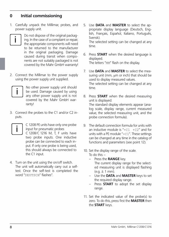
0 Initial commissioning
1. Carefully unpack the Millimar, probes, and power supply unit.
iDo not dispose of the original packag-ing. In the case of a complaint or repair, the appropriate components will need to be returned to the manufacturer in the original packaging. Damage caused during transit when compo-nents are not suitably packaged is not covered by the Mahr GmbH warranty!
2. Connect the Millimar to the power supply using the power supply unit supplied.
iNo other power supply unit should be used. Damage caused by using any other power supply unit is not covered by the Mahr GmbH war-ranty!
3. Connect the probes to the C1 and/or C2 in-puts.
iC 1208 PE units have only one probe input for pneumatic probesC 1208/C 1216 M, T, F units have two probe inputs. One inductive probe can be connected to each in-put. If only one probe is being used, this should always be connected to the C1 input.
4. Turn on the unit using the on/off switch. The unit will automatically carry out a self-
test. Once the self-test is completed the word “DEUTSCH” flashes“.
5. Use DATA and MASTER to select the ap-propriate display language (Deutsch, Eng-lish, Français, Español, Italiano, Português, Svensk).
The selected setting can be changed at any time.
6. Press START when the desired language is displayed.
The letters “MM” flash on the display.
7. Use DATA and MASTER to select the mea-suring unit (mm, µm or inch) that should be used to display measured values.
The selected setting can be changed at any time.
8. Press START when the desired measuring unit is displayed.
The standard display elements appear (ana-log scale, display range, current measured value, the selected measuring unit, and the probe connection formula).
9. The default connection formula for units with an inductive module is “+C1 +C2” and for units with a PE module “+C1”. These settings can be changed at any time in the catalog of functions and parameters (see point 12).
10. Set the display range of the scale. To do this –
– Press the RANGE key. The current display range for the select-
ed measuring unit is displayed flashing (e.g. ± 1 mm).
– Use the DATA and MASTER keys to set the required display range.
– Press START to adopt the set display range.
11. Set the indicated value of the probe(s) to zero. To do this, press first the MASTER then the START keys.
9Mahr GmbH, Millimar C1208/C1216
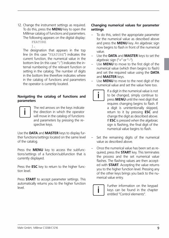
12. Change the instrument settings as required. To do this, press the MENU key to open the Millimar catalog of functions and parameters. The following appears on the digital display: FEATURE
1. The designation that appears in the top
line (in this case “FEATURE”) indicates the current function, the numerical value in the bottom line (in this case “1”) indicates the in-ternal numbering of the relevant function or setting in the catalog. The number of digits in the bottom line therefore indicates where in the catalog of functions and parameters the operator is currently located.
Navigating the catalog of functions and parameters
iThe red arrows on the keys indicate the direction in which the operator will move in the catalog of functions and parameters by pressing the re-spective keys.
Use the DATA and MASTER keys to display fur-ther functions/settings located on the same level of the catalog.
Press the MENU key to access the subfunc-tions/settings of a function/subfunction that is currently displayed.
Press the ESC key to return to the higher func-tion level.
Press START to accept parameter settings. This automatically returns you to the higher function level.
Changing numerical values for parameter settings
– To do this, select the appropriate parameter for the numerical value as described above and press the MENU key. An algebraic sign now begins to flash in front of the numerical value.
– Use the DATA and MASTER keys to set the algebraic sign (“+” or “–”).
– Use MENU to move to the first digit of the numerical value (which then begins to flash) and set the required value using the DATA and MASTER keys.
– Use MENU to move to the next digit of the numerical value and set the value here too.
iIf a digit in the numerical value is not to be changed, simply continue to press MENU until the next digit that requires changing begins to flash. If a digit is unintentionally skipped, return to it by pressing ESC and change the digit as described above. If ESC is pressed when the algebraic sign is flashing, the final digit of the numerical value begins to flash.
– Set the remaining digits of the numerical value as described above.
– Once the numerical value has been set as re-quired, press the START key. This terminates the process and the set numerical value flashes. The flashing values are then accept-ed with START. Accepting the value returns you to the higher function level. Pressing any of the other keys brings you back to the nu-merical value entry.
iFurther information on the keypad keys can be found in the chapter entitled “Control elements”.

10 Mahr GmbH, Millimar C1208/C1216
11Mahr GmbH, Millimar C1208/C1216
1 General points
The Millimar C 1208/1216 is an electronic length measuring and evaluating instrument for use in a production environment. It is available in two versions:C 1208/C 1216 M, T, F: one or two inductive probes can be connected.C 1208 PE: a pneumatic sensor (air plug gage, air ring gage) can be connected.
Both versions are suitable for dynamic and static measurement.The current measured value is shown on the dis-play in both analog format (as a value on a scale) and digital format (as a numerical value below the scale). If required, numerical values from two probes can also be displayed simultaneously. However, this is only possible when performing static measurements.
Resolution can be set in several stages as re-quired. The lowest possible resolution with a C 1208 unit is 0.1 µm and 0.01 µm with a C 1216 unit.As well as displaying the current measured value, it is also possible to display the aggregate of, or the difference between, measured values from two probes. The required connection formula between the two channels is indicated on the display.
Internal measured value memories also enable the acquisition of maximum, minimum and mean values over a certain period of time (mea-surement period). At the end of the measure-ment period, these values are used to calculate the features, which are then indicated on the display.The measurement period can be set using the Millimar keypad, an external control signal or an internal timer.
Depending on the interface protocol that is se-lected, the RS 232 interface enables measure-ment results to be transferred to/queried by an external computer and instrument parameters to be queried or set by a computer. It is also pos-sible to connect a printer.Other instruments such as other instruments from the Millimar range, or a programmable controller can be connected to the interface for auxiliary appliances (I/O).
The Millimar C 1208/C 1216 offers:
• Staticordynamicmeasurement• Analogresultsdisplay• Digitalresultsdisplay• Easy-to-adjust functions using 8 function
keys• Fast access topopular functionsbyassign-
ing up to 6 functions to the freely program-mable SELECT key
• ConvenientprogrammingwithaconnectedWindows-based computer using MarTalk.
• RS232interfaceforsequencecontrolorforintegration into a quality assurance system
• (C1216unitsonly!)Parallelinterfaceforauxil-iary appliances with three optocoupler digital inputs and three optocoupler digital outputs and one analog output.
• Saving the last 400 measured values inMillimar and reading these out over the RS 232 interface.
• Customer calibration

12 Mahr GmbH, Millimar C1208/C1216
2 Control elements
Display (1)
All important measurement information is de-picted on the display – measured value (analog and digital), connection formula, display range (not when 2 features are displayed simultane-ously), measuring unit, indication of whether the displayed value is a maximum, minimum, aggre-gate or differential value, and indication (letter “T”) that the measured value memory is active (if applicable).It also displays the catalog of functions and pa-rameters.
Keypad (2)
The keypad comprises 8 keys. Four keys are used to navigate Millimar’s catalog of functions and parameters (DATA, MENU, MASTER and ESC).
Fig. 1 Front of Millimar C 1208/C 1216
1 Display2 Keypad3 Status lamps
13Mahr GmbH, Millimar C1208/C1216
MENU
Displays Millimar’s catalog of functions and pa-rameters.In the catalog of functions and parameters itself, this key is used to switch between subfunctions and enter numerical values. When entering numerical values, this key is used to move from one digit to the next (to the right). The selected digit flashes to show that it can be changed.
DATA
Used to navigate the catalog of functions and parameters and to begin data transfer. Within a function level of this catalog, this key is used to scroll up in order to show further func-tions/settings.
When setting numerical values, this key is used to increase the value of the flashing (and there-fore selected) digit by 1. If the number 9 is dis-played when the DATA key is pressed, this will change to 0.
iPress the START key to stop entry of numerical values. The numerical value that has been entered flashes. Press the START key again to adopt the numerical value.
If the DATA key is pressed at the end of a mea-surement and the interface has been set appro-priately, data is transferred to a connected PC, see chapter 14.
MASTER
In measuring mode, this key is used to start a master measurement.In the catalog of functions and parameters, this key is used within the selected function level to scroll down in order to show further functions/settings.
When setting numerical values in the catalog of functions and parameters, this key is used to de-crease the value of the flashing (and therefore selected) digit by 1. If 0 is displayed when the MASTER key is pressed, this will change to the number 9.
iPress the START key to stop entry of numerical values. The numerical value that has been entered flashes. Press the START key again to adopt the numerical value.
14 Mahr GmbH, Millimar C1208/C1216
ESC
This key is used in the catalog of functions and parameters to move from function sublevels to the higher level.
When entering numerical values, this key is used to move from one digit to the next (to the left). The selected digit flashes to show that it can be changed.
Pressing ESC when in setup mode exits this mode.
Restoring factory settingsPressing the ESC key immediately after switching on the unit initializes the instrument, restoring all the original factory settings. This is indicated by “INITALL” appearing on the display.
— Hold down the ESC key when switching on Millimar. The unit boots up and “INITALL” is displayed. Once the boot-up process has been completed “DEUTSCH (4.3.1)” flashes.
— Use the DATA and MASTER keys to set the display language and press START (twice) to adopt the selected language. “MM (4.4.1)“ flashes.
— Use the DATA and MASTER keys to set the measuring unit and press START (twice) to adopt the selected unit. “MAHR“ appears on the display, followed by the standard display elements.

15Mahr GmbH, Millimar C1208/C1216
* additional settings for C 1216 instruments
RANGE
Opens the selection list in which the size of the display range can be selected. The increments of the analog scale and the number format of the numerical display are changed accordingly. The following increments are available for the differ-ent measuring units:
mm µm inch
10 10 000 0.3
3 3 000 0.1
1 1 000 0.03
0.3 300 0.01
0.1 100 0.003
0.03 30 0.001
0.01 10 0.0003
0.003 3 0.0001
0.001* 1* 0.00003*
0.0003* 0.3* 0.00001*
I — — — — — I I — — — — — I I — — — — — I
"I — — — — — I“ stands for “tolerance limited”. This means that the display range depicts the range between the lower and upper tolerance limit. This can be used with the analog display to quickly identify where the current measured val-ue lies in the tolerance range. This enables trends (e.g. ever larger dimensions) to be rapidly iden-tified, enabling appropriate countermeasures to be implemented.
iAs tolerance ranges vary, the letter-ing of the analog scale (the numeri-cal values) is removed.
iThe unit of measurement of the display (mm, µm or inch) cannot be changed with this key. If an al-ternate unit of measurement is re-quired for the display, this has to be selected via the catalog of functions and parameters under “SETTING” --> “UNIT”. The current measuring unit is indicated in the bottom line of the display.
16 Mahr GmbH, Millimar C1208/C1216
SELECT
This key is freely programmable. Up to six fre-quently used functions or subfunctions can be assigned to this key. To assign a function to the key, simply select the required function in the catalog of functions and parameters and press the SELECT key. The message “SELECT x” appears, whereby the “x” stands for one of the key’s six memory locations.
iIt is not possible to save different pa-rameter values (e.g. the factor “0.3”) or settings (e.g. the measuring unit “MM”) to the SELECT key.
If SELECT is pressed in measuring mode, the function assigned to memory location 1 is dis-played. Continually pressing SELECT scrolls through the other functions saved to the key.
Press MENU to make parameter settings or en-ter numerical values for the selected function. Settings and values are selected, changed, set, and accepted as indicated in the catalog of func-tions and parameters.
If all the assignments of the key are to be de-leted, select “SETTING” --> “CLR-SEL (4.8)” in the catalog of functions and parameters then press the MENU key. Answer the Safety inquiry by pressing START.
iPress ESC to exit deletion of SELECT key assignments. The DATA and MASTER keys have no effect here.
17Mahr GmbH, Millimar C1208/C1216
TEST (indication of raw values)
This function is required for moving and correct-ly positioning (i.e. setting up) the probe in the measuring device as the current position of the probe(s) is indicated directly i.e. without being multiplied by a factor or corrected by the master correction value.The measured value of channel C1 is indicated on the analog scale and in the upper line of the numerical display. The measured value of C2 is indicated in the lower line of the numerical dis-play. On pressing either the DATA or MASTER key, the word CALIBRA. and the currently set dis-play range are indicated. If one of the two keys is pressed again, the display range is enlarged or reduced according to the programmed incre-ments and the scaling of the analog scale and the number format of the numerical display are changed accordingly.
Press either the ESC or START key to exit setup mode.
START
This key is used to select settings or set numeri-cal values in the catalog of functions and pa-rameters. The most recently selected settings and numerical values flash. Press the START key again to adopt the flashing settings. The display then moves to the next level up in the catalog of functions and parameters. The changed settings are used for the next measurement.
Press START in the first (1., …, 4.) or second (1.1, …, 4.9) function level to exit the catalog of func-tions and parameters.
Pressing START in setup mode (TEST) exits setup mode.
Depending on the settings selected under “PROCESS“ (of measurement), pressing START initiates individual measurements or measuring cycles. If the appropriate settings have been se-lected, START can also be used to end measure-ments (see chapter 10.2).
Status lamps (3)
These are used to indicate the positioning of the current measured value or result in relation to the tolerance limits. The colors used to indicate values that are within tolerances, that are border-line, or that breach tolerances can be selected in the catalog of functions and parameters under “FEATURE”--> “TOLERNCE”--> “COLOR”.
18 Mahr GmbH, Millimar C1208/C1216
Serial RS 232 interface (rear side of Millimar)
A printer or computer can be connected to this 9 channel interface. If necessary (e.g. if the mea-sured value memory is full and there is a risk that the first entry will be overwritten by the most recent), data that has already been acquired can be printed out on a connected printer and then deleted.
If a computer is connected, the following pro-cesses can be executed depending on the set-ting of the Millimar interface– Measured values can be transferred to, or
queried from, the computer– Parameter settings can be changed or que-
ried by the computer– Measurements can be initiated or terminat-
ed by the computer.
Data saved on the computer can be processed using appropriate programs (statistics programs, QA programs) – see chapter 14 “Using the serial interface (RS 232)”.
Parallel interface (rear side of Millimar)
The 25-pin interface marked with “I/O” enables data to be transferred to and from other instru-ments in the Millimar range (e.g. footswitches) or a programmable controller for e.g. automatic sorting processes (see chapter 15 “Using the par-allel I/O interface”).
Connection for power supply unit (rear side of the Millimar )
The power supply unit is plugged into the con-nection marked with “9 V =”. This power supply unit covers a voltage range between 100 V and 240 V and a frequency range of between 47 Hz and 63 Hz.
iNo other power supply must be used.
On/off switch (rear side of the Millimar)
Millimar is switched on and off using the on/off switch. Once the unit has been switched on, the soft-ware boots and the display indicates in sequence the type of instrument (C 1208 or C 1216), the software version number, the compatibility of the probe inputs, and finally the standard display elements.
19Mahr GmbH, Millimar C1208/C1216
3 Performing basic settings
8. Press START again to adopt the flashing display language. The display then returns to the catalog of functions and parameters item “LANGUAG. (4.3)”.
iIf at this point either the MASTER or DATA key is pressed instead of START, the display returns to the language selec-tion list (cf. point 6). An alter-native display language can be selected.
9. If no further settings are to be made in the catalog of functions and parameters, press the START key. The standard display ele-ments appear.
If further settings are necessary, navigate to the appropriate point of the catalog of functions and parameters using the ESC, MASTER, DATA and MENU keys and carry out the settings as required.
3.1 Selecting the display language
The information, functions and settings that ap-pear on the Millimar display are available in the following languages :
German English French
Spanish Italian Portuguese
Swedish
The appropriate language can be selected when commissioning the instrument (see chapter “Initial commissioning”). However, the language selection made at this point can be changed at any time. To do this:
1. Press the MENU key when the standard display elements are shown. The catalog of functions and parameters is opened and the setting “FEATURE (1)” is displayed.
2. Use the DATA and MASTER keys to select the setting “SETTING (4)”.
3. Press MENU again. The setting “DISPLAY (4.1)” is displayed.
4. Use the DATA and MASTER keys to select the setting “LANGUAG. (4.3)”.
5. Press MENU again. The most recently se-lected language setting flashes.
6. Use the DATA and MASTER keys to se-lect the new display language (ENGLISH, FRANC., ITAL., ESPANOL, PORTUG., SVENSKA or DEUTSCH).
7. Press START. The selected display language flashes.

20 Mahr GmbH, Millimar C1208/C1216
3.2 Setting the contrast
The contrast can be adjusted to the light condi-tions of the location. On delivery, contrast is set to medium. However, this can be changed at any time. To do this:
1. Press the MENU key when the standard display elements are shown. The catalog of functions and parameters is opened and the setting “FEATURE (1)” is displayed.
2. Use the DATA and MASTER keys to select the setting “SETTING (4)”.
3. Press MENU again. The setting “DISPLAY (4.1)” is displayed.
4. Press MENU again. The setting “FEATURE (4.1.1)” is displayed.
5. Use the DATA and MASTER keys to select the setting “CONTR. (4.1.3)”.
6. Press MENU again. Setting “CONT.+/-” and the numerical value of the current con-trast setting are displayed.
7. Use the DATA and MASTER keys to select the new contrast (16, 13, .….., 1, 0).
iThe highest contrast setting is “16” and the lowest “1”. When “0” is selected, the display be-comes blank. This setting is not recommended!
8. Press START. The numerical value of the con-trast setting that has been selected flashes.
9. Press START again to adopt the flashing contrast setting. The display then returns to the catalog of functions and parameters item “CONTR. (4.1.3)”.
iIf at this point either the DATA or MASTER key is pressed in-stead of START, the dis play returns to the contrast set ting selection list (cf. point 7). The contrast can be changed again.
10. If no further settings are to be made in the catalog of functions and parameters, press the START key. The standard display ele-ments appear.
If further settings are necessary, navigate to the appropriate point of the catalog of functions and parameters using the ESC, MASTER, DATA and MENU keys and carry out the settings as required.
21Mahr GmbH, Millimar C1208/C1216
3.3 Setting the unit of measurement
Tolerances are usually set for workpiece mea-surements and deviations using a specific unit of measurement. To simplify checking, it is recom-mended that this specific unit of measurement is also used to display measured values. Workpiece measurements and deviations can be depicted on the Millimar in the following units of mea-surement: millimeters, micrometers or inches.
The unit of measurement can be selected when commissioning the instrument (see chapter “Initial commissioning”). However, the unit se-lected during this procedure can by changed at any point. To do this:
1. Press the MENU key when the standard display elements are shown. The catalog of functions and parameters is opened and the setting “FEATURE (1)” is displayed.
2. Use the DATA and MASTER keys to select
the setting “SETTING (4)”.
3. Press MENU again. The setting “DISPLAY (4.1)” is displayed.
4. Use the DATA and MASTER keys to select the setting “UNIT (4.4)”.
5. Press MENU again. The current unit of mea-surement flashes.
6. Use the DATA and MASTER keys to select the new unit of measurement (MM, INCH or MICRON)
7. Press START. The selected unit of measure-ment flashes.
8. Press START again to adopt the flashing unit of measurement. The display then returns to the catalog of functions and parameters item “UNIT (4.4)”.
iIf at this point either the DATA or MASTER key is pressed in-stead of START, the display returns to the unit of measure-ment selection list (cf. point 6). The unit of measurement can be changed again.
9. If no further settings are to be made in the catalog of functions and parameters, press the START key. The standard display ele-ments appear. The selected measuring unit is indicated in the bottom line of the display as mm, µm or inch.
If further settings are necessary, navigate to the appropriate point of the catalog of functions and parameters using the ESC, MASTER, DATA and MENU keys and carry out the settings as required.
22 Mahr GmbH, Millimar C1208/C1216
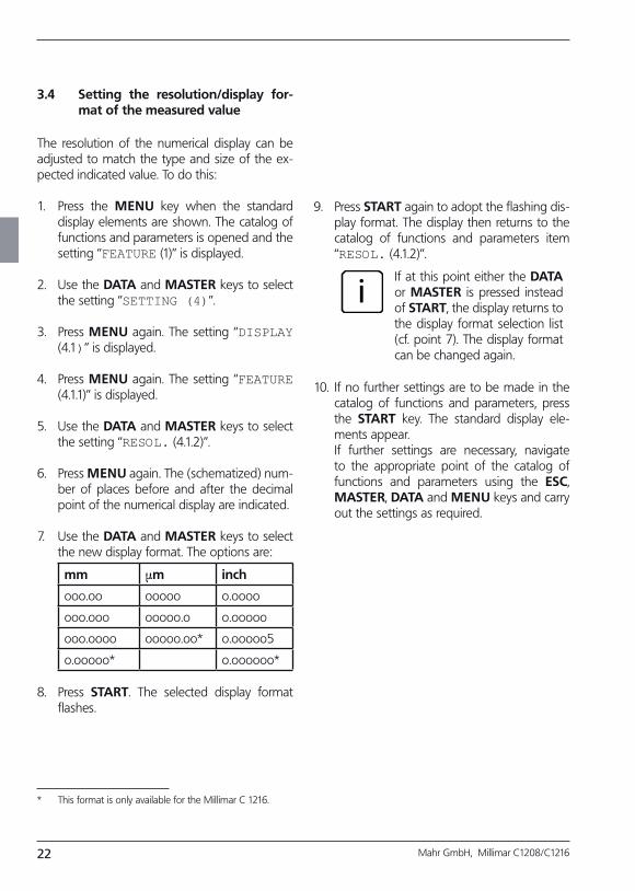
3.4 Setting the resolution/display format of the measured value
The resolution of the numerical display can be adjusted to match the type and size of the ex-pected indicated value. To do this:
1. Press the MENU key when the standard display elements are shown. The catalog of functions and parameters is opened and the setting “FEATURE (1)” is displayed.
2. Use the DATA and MASTER keys to select the setting “SETTING (4)”.
3. Press MENU again. The setting “DISPLAY (4.1)” is displayed.
4. Press MENU again. The setting “FEATURE (4.1.1)” is displayed.
5. Use the DATA and MASTER keys to select the setting “RESOL. (4.1.2)”.
6. Press MENU again. The (schematized) num-ber of places before and after the decimal point of the numerical display are indicated.
7. Use the DATA and MASTER keys to select the new display format. The options are:
mm µm inch
ooo.oo ooooo o.oooo
ooo.ooo ooooo.o o.ooooo
ooo.oooo ooooo.oo* o.ooooo5
o.ooooo* o.oooooo*
8. Press START. The selected display format flashes.
9. Press START again to adopt the flashing dis-play format. The display then returns to the catalog of functions and parameters item “RESOL. (4.1.2)”.
iIf at this point either the DATA or MASTER is pressed instead of START, the display returns to the display format selection list (cf. point 7). The display format can be changed again.
10. If no further settings are to be made in the catalog of functions and parameters, press the START key. The standard display ele-ments appear.
If further settings are necessary, navigate to the appropriate point of the catalog of functions and parameters using the ESC, MASTER, DATA and MENU keys and carry out the settings as required.
* This format is only available for the Millimar C 1216.
23Mahr GmbH, Millimar C1208/C1216
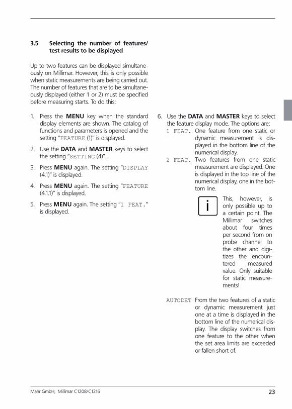
3.5 Selecting the number of features/test results to be displayed
Up to two features can be displayed simultane-ously on Millimar. However, this is only possible when static measurements are being carried out. The number of features that are to be simultane-ously displayed (either 1 or 2) must be specified before measuring starts. To do this:
1. Press the MENU key when the standard display elements are shown. The catalog of functions and parameters is opened and the setting “FEATURE (1)” is displayed.
2. Use the DATA and MASTER keys to select the setting “SETTING (4)”.
3. Press MENU again. The setting “DISPLAY (4.1)” is displayed.
4. Press MENU again. The setting “FEATURE (4.1.1)” is displayed.
5. Press MENU again. The setting “1 FEAT.” is displayed.
6. Use the DATA and MASTER keys to select the feature display mode. The options are:1 FEAT. One feature from one static or
dynamic measurement is dis-played in the bottom line of the numerical display.
2 FEAT. Two features from one static measurement are displayed. One is displayed in the top line of the numerical display, one in the bot-tom line.
iThis, however, is only possible up to a certain point. The Millimar switches about four times per second from on probe channel to the other and digi-tizes the encoun-tered measured value. Only suitable for static measure-ments!
AUTODET From the two features of a static or dynamic measurement just one at a time is displayed in the bottom line of the numerical dis-play. The display switches from one feature to the other when the set area limits are exceeded or fallen short of.
24 Mahr GmbH, Millimar C1208/C1216
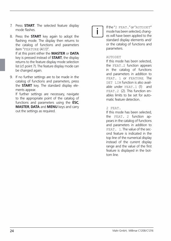
7. Press START. The selected feature display mode flashes.
8. Press the START key again to adopt the flashing mode. The display then returns to the catalog of functions and parameters item “FEATURE (4.1.1)”.
If at this point either the MASTER or DATA key is pressed instead of START, the display returns to the feature display mode selection list (cf. point 7). The feature display mode can be changed again.
9. If no further settings are to be made in the catalog of functions and parameters, press the START key. The standard display ele-ments appear.
If further settings are necessary, navigate to the appropriate point of the catalog of functions and parameters using the ESC, MASTER, DATA and MENU keys and carry out the settings as required.
iIf the “2 FEAT.” or “AUTODET” mode has been selected, chang-es will have been applied to the standard display elements and/or the catalog of functions and parameters.
AUTODETIf this mode has been selected, the FEAT.2 function appears in the catalog of functions and parameters in addition to FEAT. 1 or FEATURE. The DET LIM function is also avail-able under FEAT.1 (1) and FEAT.2 (2). This function en-ables limits to be set for auto-matic feature detection.
2 FEAT.If this mode has been selected, the FEAT. 2 function ap-pears in the catalog of functions and parameters in addition to FEAT. 1. The value of the sec-ond feature is indicated in the top line of the numerical display instead of the current display range and the value of the first feature is displayed in the bot-tom line.
25Mahr GmbH, Millimar C1208/C1216
4 Positioning the probe in the measuring device (setup)
5. Move the probe by hand or using a position-ing device if available, so that the measured value is zero.
6. Clamp the probe in this position.
7. Press either the ESC or START key to exit setup mode.
To use a probe to take measurements across the full measuring range available, it has to be cor-rectly positioned in the measuring instrument. If this is not the case, the measuring range can be exceeded or fallen short of.
1. Insert the probe into the measuring instru-ment.
2. Fit a setting master or a workpiece of known size into the measuring instrument.
3. Press the TEST key. The measured value transmitted by the
probe across channel C1 is depicted on the scale and in the top line of the numerical dis-play. If applicable, the bottom line of the nu-merical display depicts the measured value transmitted by the probe across C2.
4. If the Millimar display range is too small or large to allow the probe to be correctly po-sitioned, it can be changed using the DATA and MASTER keys. To do this: Press either the DATA or MASTER key. The current dis-play range is shown. Press one of the two keys again to resize the display range in line with the programmed increments and to change the analog scale accordingly.
26 Mahr GmbH, Millimar C1208/C1216
5 Aligning probe sensitivity
When calibrating the sensitivity of the probe con-nected to C1, the probe is used to record the measured values at two measuring points that are known to be a certain distance apart. Gage blocks and setting masters of various sizes are particularly suited to this purpose and can be used to calibrate the entire measuring chain. This means that production-related deviations in sen-sitivity affecting both the display and probe can be measured and corrected. The setting masters and/or gage blocks should differ by at least 500 µm for a Millimar C 1216 with a measuring range of ± 2000 µm. For measurements within a range of ±200 µm, or for the Millimar C 1208, the dif-ference should be at least 100 µm.
Probe sensitivity is subject to variations caused during production. These variations are usually less than 0.5 %. Deviations such as this can be tolerated for many measuring tasks. In these instances, there is no need to align sensitivity. However, in the case of differential measure-ments (C1-C2), these deviations can distort mea-surement results to an unacceptable extent.
iThe sensitivity of the display is also subject to variations caused during production processes. If only the Millimar display is to be calibrated, a nominal value selector (e.g. the 1283 WN) can be attached to the C 1208/C 1216 instead of the probe. However, to enable precise measurements, the entire measur-ing chain should be calibrated.
The C 1208/C 1216 offers two options for cor-recting these deviations – firstly, the signals of both probes/channels can be multiplied with a common factor, or secondly, the sensitivity of the probe connected to C1 can be determined (calibrated) then the sensitivity of the probe con-nected to C2 aligned to that of the first probe.
27Mahr GmbH, Millimar C1208/C1216
5.1 Calibrating the sensitivity of the probe connected to C1
1. Insert the smaller gage block or setting mas-ter into the measuring instrument.
2. Press the MENU key. The catalog of func-tions and parameters item “FEATURE (1)” is displayed.
3. Press the DATA key. “SETTING (4)” is dis-played.
4. Press the MENU key again. The catalog of functions and parameters item “DISPLAY (4.1)” is displayed.
5. Press the DATA key again. “CALIBR. (4.9)” is displayed.
6. Press the MENU key. “PASSWRD” is dis-played with seven zeros below it, the first of which flashes.
7. Enter the password (any seven-digit num-ber). The default password (factory setting) is always (1 000 000).
8. Press START to display “CHAN1 (4.9.1)” and then MENU. “MIN C1” is displayed along with a numerical value that will vary depend-ing on the measuring unit that has been se-lected for the display – -0.3 mm or -300 µm or –0.011811 inch.
9. Use the DATA and MASTER keys to set the displayed numerical value to match the nominal value of the smaller gage block.
10. Press the START key to confirm the set value. Pressing START again starts the mea-surement on the smaller gage block and the raw value of the measurement is displayed.
11. Press START again to adopt the measured value on the smaller gage block. “MAX C1” is then displayed along with a numerical value that will vary depending on the measuring unit that has been selected for the display – 0.3 mm or 300 µm or 0.011811 inch.
12. Remove the smaller gage block and insert the larger gage block into the measuring in-strument.
13. Use the DATA and MASTER keys to change the displayed numerical value to match the nominal value of the larger gage block.
14. Press the START key to confirm the changed numerical value. Pressing START again starts the measurement on the larger gage block and the raw value of the measurement is displayed.
15. Press START to adopt this value. A correction factor is calculated based on the
measured values and the entered nominal values. This factor is then used for all subse-quent measurements to multiply measured values from the probe connected to C1.
iThe correction factors can range between 0.3 and 3.0. If the fac-tor that is calculated exceeds this range, the previous factor remains valid and the error mes-sage “OUT LIM” is displayed.
16. If no further settings are to be made in the catalog of functions and parameters, press the START key. The standard display ele-ments appear.
If further settings are necessary, navigate to the appropriate point of the catalog of functions and parameters using the ESC, MASTER, DATA and MENU keys and carry out the settings as required.
28 Mahr GmbH, Millimar C1208/C1216
5.2 Aligning the sensitivity of the probe connected to C2 to that of the probe connected to C1 (instruments with inductive probes only)
10. Press START. The displayed value changes to 0.000. In addition “ABGL LO” is output.
11. Exchange the smaller gage block for the larger one.
12. Use the DATA and MASTER keys to set the difference in size of the two gage blocks as precisely as possible.
13. Press START. The sensitivity of the probe connected to C2 is aligned to that of the probe connected to C1
14. If no further settings are to be made in the catalog of functions and parameters, press the START key. The standard display ele-ments appear.
If further settings are necessary, navigate to the appropriate point of the catalog of functions and parameters using the ESC, MASTER, DATA and MENU keys and carry out the settings as required.
iIf two probes are being used and if the measured values from both probes are interlinked, the sensitivity of the probe connected to C2 must be aligned to that of the probe con-nected to C1. However, alignment is only possible as long as the sensi-tivity differential does not exceed ± 1.3 %.
In addition, the probe connected to C1 must be calibrated before align-ing the sensitivities of both probes (see chapter 5.1). For aligning the sensitivities, two gage blocks of dif-ferent size are necessary.
1. Fix the probe connected to C2 in a suitable mounting device, e.g. a measuring stand, and allow it to contact the smaller of the two gage blocks.
2. Press MENU to open the catalog of func-tions and parameters.
3. Use the DATA and MASTER keys to select “SETTING (4)”.
4. Press MENU again. “DISPLAY (4.1)” is dis-played.
5. Press the DATA key again. “CALIBR. (4.9)” is displayed.
6. Press the MENU key. “PASSWRD” is dis-played with seven zeros below it, the first of which flashes.
7. Enter the password (1 000 000) and confirm it with START.
8. Press MASTER to display “C2 (4.9.2)”.
9. Set the display to OFFS LO with MENU.

29Mahr GmbH, Millimar C1208/C1216
30 Mahr GmbH, Millimar C1208/C1216
6 Inputting settings for calculation and display of a feature
6.1 Setting the factor for correcting the indicated value of a feature
Certain measuring tasks can require a factor oth-er than 1 to be input for the connection formula. Such tasks include measuring the eccentricity of a rotating workpiece or indirect measurement of a workpiece by contacting via a lever that exhib-its a lever ratio other than 1:1. The (MAX-MIN) function has to be used to eval-uate eccentricity. The differential between the largest and smallest measured values is formed. As measurement is carried out through 360°, the result for factor 1 is equal to double the eccen-tricity value. Inputting a value of 0.5 enables the user to directly view the actual eccentricity with-out having to perform further calculations based on the indicated values. Inputting a value of 0.5 halves the resultant value, thus correctly indicat-ing eccentricity.
If indirect contact is made with the workpiece via a lever with a lever ratio other than 1:1, the indicated value is distorted in proportion to the lever ratio. If there is a lever ratio of 1:5 (point of contact on the workpiece – lever pivot point – contact point on the lever), the indicated value is 5 times larger than the actual deviation. A fac-tor of (1 : 5 =) 0.2 must be input in order that the deviation can be read directly for a lever ratio of 1:5.
Depending on the device type, either one pneu-matic or up to two inductive probes can be con-nected to the Millimar C 1208/C 1216. One or two features are calculated and displayed based on raw value(s) (see chapter “Selecting the num-ber of features/test results to be displayed”). A connection formula is required in order to calcu-late the feature (F). This formula consists of both a freely selectable factor and the raw value(s) from the probe(s). C 1208 PE, C 1208/C 1216 M, F, T
F = Factor × (± C1)
C 1208/C 1216 M, F, T
F = Factor × (± C2)F = Factor × (± C1 ± C2)
If the extent of a workpiece’s deviation from a nominal dimension is to be displayed rather than its absolute value, the value of the nominal di-mension must also be established.
31Mahr GmbH, Millimar C1208/C1216
In addition, the algebraic sign of the indicated value can be changed by the factor’s algebraic sign. Example: A feature is calculated using the factor -0.5 and the formula -C1. The direct measured value (the raw value) is 1000 µm.Feature = Factor × Formula = -0.5 × (-(1000 µm)) = +500 µm
Setting the factor for correcting the indicated value
1. Press the MENU key. The catalog of func-tions and parameters item “FEATURE (1)” is displayed.
2. Press the MENU key again. “FACTOR (1.1)” is displayed.
3. Press the MENU key for the third time. The current numerical value of the factor is dis-played under “Factor” with a flashing alge-braic sign.
4. Change the algebraic sign and numerical value as required (see section “Changing numerical values for parameter settings” in chapter 0).
5. Once the algebraic sign and numerical value have been set as required, press the START key. This terminates the process and the set value flashes.
6. Press the START key again to adopt the flashing value as the current setting. The dis-play then returns to the catalog of functions and parameters item “FACTOR (1.1)”.
If at this point either the MASTER or DATA key is pressed instead of START, the display returns to the numerical value setting stage (cf. point 4). The indicated numerical value can be changed again.
7. If no further settings are to be made in the catalog of functions and parameters, press the START key. The standard display ele-ments appear.
If further settings are necessary, navigate to the appropriate point of the catalog of functions and parameters using the ESC, MASTER, DATA and MENU keys and carry out the settings as required.
iIf the factor of the connection formula has to be changed frequently, this function from the catalog of functions and parameters can be assigned to the SELECT key to enable rapid access.
32 Mahr GmbH, Millimar C1208/C1216
6.2 Selecting a channel or channel connection (formula)
A connection formula is needed in order to cal-culate a feature. This consists of a factor that de-termines the size of the indicated value (cf. chap-ter 6.1) and a channel connection, the “formula”.
Setting the connection formula
1. Press the MENU key. The catalog of func-tions and parameters item “FEATURE (1)” is displayed.
2. Press the MENU key again. “FACTOR (1.1)” is displayed.
3. Use the DATA and MASTER keys to select the setting “FORMULA (1.3)”.
4. Press the MENU key. The current connection flashes.
5. Use the MASTER and DATA keys to set the connection that is to be used. The options are: +C1 Raw value from the probe at jack
C1 -C1 Inverted raw value from the
probe at jack C1 +C2 Raw value from the probe at jack
C2 -C2 Inverted raw value from the
probe at jack C2 C1 + C2 Aggregate of the raw values
from the probes at jacks C1 and C2
C1 - C2 Difference between the raw val-ues. If C2 < C1, the difference is positive, if C2 > C1, it is negative
C2 – C1 Difference between the raw val-ues. If C2 > C1, the difference is positive, if C2 < C1, it is negative
-C1-C2 The difference between both inverted raw values from the probes at jacks C1 and C2
6. Press START once the desired formula is dis-played. The formula flashes.
7. Press the START key again to adopt the flashing formula as the current setting. The display then returns to the catalog of func-tions and parameters item “FORMULA (1.3)”.
If at this point either the MASTER or DATA key is pressed instead of START, the display returns to the connection selection list (cf. point 5). If required, another formula can be selected in place of the one currently indi-cated.
8. If no further settings are to be made in the catalog of functions and parameters, press the START key. The standard display ele-ments appear.
If further settings are necessary, navigate to the appropriate point of the catalog of functions and parameters using the ESC, MASTER, DATA and MENU keys and carry out the settings as required.
iIf the formula has to be changed frequently, this function from the catalog of functions and parameters can be assigned to the SELECT key to enable rapid access.

33Mahr GmbH, Millimar C1208/C1216
34 Mahr GmbH, Millimar C1208/C1216
7 Selecting a feature
iOne or two features can be simul-taneously calculated and displayed using Millimar. Set whether one or two features are to be displayed by going to “SETTING” -> “DISPLAY” -> “FEATURE (4.1.1)” in the catalog of functions and parameters (see chap-ter “Selecting the number of fea-tures/test results to be displayed”).
1. Press the MENU key. The catalog of func-tions and parameters item “FEATURE (1)” (if only one feature is being displayed) or “FEAT. 1 (1)” (if two features are being dis-played) appears.
2. Press the MENU key again. “FACTOR (1.1)” is displayed.
3. Use the DATA and MASTER keys to select “FNCTION (1.2)”.
4. Press the MENU key. The current feature flashes.
5. Use the DATA and MASTER keys to select the function for the feature to be calculated. The options are:
NORMAL The current measured value calculated using the selected connection formula is contin-uously displayed throughout the measurement period.
MAXIMUM The largest measured value (maximum value) is continu-ously displayed throughout the measurement period. The indicated value only changes when the so far maximum value is exceeded.
MINIMUM The smallest measured value (minimum value) is continu-ously displayed throughout the measurement period. The indicated value only changes when a measured value falls below the so far minimum value.
MAX – MIN The difference between the smallest measured value so far (minimum value) and the largest measured value so far (maximum value) is continu-ously displayed throughout the measurement period. The indicated value only changes when a measured value falls below the minimum value or exceeds the maximum value.
MAX + MIN The aggregate of the small-est measured value so far (minimum value) and the largest measured value so far (maximum value) is continu-ously displayed throughout the measurement period. The indicated value only changes when a measured value falls below the minimum value or exceeds the maximum value.
35Mahr GmbH, Millimar C1208/C1216
MEANVAL The mean value of all the individual measured values is continuously displayed through out the measure-ment period. The mean value is calculated according to the follo wing formula:
(Measured value 1 + Mea-sured value 2 + ..... + Mea-sured value x) ÷ Number x of in dividual measured values.
6. Press START once the desired function (the desired feature) is displayed. The function now flashes.
7. Press START again to adopt the flashing set-ting (feature). The display then returns to the catalog of functions and parameters item “FNCTION (1.2)”.
If at this point either the MASTER or DATA key is pressed instead of START, the display returns to the feature selection list (cf. point 5 of this section). A different function (a dif-ferent feature) can then be selected.
8. If only one feature is indicated on the display, press START to exit the catalog of functions and parameters. If, however, two features are displayed, follow the instructions in points 9 to 17 of this section.
9. Press the ESC key. The setting “FEAT. 1” is displayed.
10. Press the MASTER key. The setting “FEAT. 2” is displayed (“2 FEAT.” must have been set under “SETTING --> DISPLAY --> FEATURE (4.1.1)”).
11. Press the MENU key again. “FACTOR (2.1)” is displayed.
12. Use the DATA and MASTER keys to select “FNCTION (2.2)”.
13. Press the MENU key. The current feature flashes.
14. Use the DATA and MASTER keys to se-lect the feature to be calculated. The choice of settings listed in point 5 are available to choose from.
15. Press START once the desired function (the desired feature) is displayed. The function now flashes.
16. Press START again to adopt the flashing set-ting (feature). The display then returns to the catalog of functions and parameters item “FNCTION (2.2)”.
17. If no further settings are to be made in the catalog of functions and parameters, press the START key. The standard display ele-ments appear. The selected feature’s desig-nation is displayed in front of the measuring result: MAX, MIN, MAX+MIN, MAX-MIN, M. The “M” here stands for mean value.
If further settings are necessary, navigate to the appropriate point of the catalog of functions and parameters using the ESC, MASTER, DATA and MENU keys and carry out the settings as required.
iIf the function/feature has to be changed frequently, this function from the catalog of functions and parameters can be assigned to the SELECT key to enable rapid access.
36 Mahr GmbH, Millimar C1208/C1216
8 Master measurement
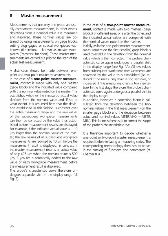
Measurements that use only one probe are usu-ally comparative measurements, in other words, deviations from a nominal value are measured and displayed. These nominal values are ob-tained by using measurements on gage blocks, setting plug gages, or special workpieces with known dimensions – known as master work-pieces (“masters” for short). These master mea-surements are carried out prior to the start of the actual test measurement.
A distinction should be made between one-point and two-point master measurements. In the case of a onepoint master measurement, contact is made with only one master (gage block) and the indicated value compared with the nominal value noted on the master. This establishes whether the measured actual value deviates from the nominal value and, if so, to what extent. It is assumed here that the devia-tion established in this fashion is constant over the entire measuring range and the raw values of the subsequent workpiece measurements can then be corrected by the value thus estab-lished before measurement results are displayed. For example, if the indicated actual value is + 10 µm larger than the nominal value of the mas-ter, the raw values of all subsequent workpiece measurements are reduced by 10 µm before the measurement result is displayed. In contrast, if the master measurement returns an actual value of only 495 µm when the nominal value is 500 µm, 5 µm are automatically added to the raw value of each workpiece measurement before the measurement result is displayed. The probe’s characteristic curve therefore un-dergoes a parallel shift in the display range (cf. Fig. 3).
In the case of a twopoint master measurement, contact is made with two masters (gage blocks) of different sizes, one after the other, and the indicated actual values are compared with the nominal values noted on the masters. Initially, as in the one-point master measurement, measurement on the first (smaller) gage block is used to establish the deviation from the nominal value which is then corrected. The probe’s char-acteristic curve again undergoes a parallel shift in the display range (see Fig. 4A). All raw values from subsequent workpiece measurements are corrected by the value thus established (i.e. re-duced if the measuring chain is too sensitive, or increased if the measuring chain is too insensi-tive). In the first stage therefore, the probe’s char-acteristic curve again undergoes a parallel shift in the display range.In addition, however, a correction factor is cal-culated from the deviation between the two nominal values in the first measurement (on the smaller gage block) and the deviation between actual and nominal values MSTR.MAX — MSTR.MIN). This factor is then used to correct the slope of the probe’s characteristic curve.
It is therefore important to decide whether a one-point or two-point master measurement is required before initiating a measuring series. The corresponding methodology then has to be set in the catalog of functions and parameters (cf. Chapter 8.1).
37Mahr GmbH, Millimar C1208/C1216
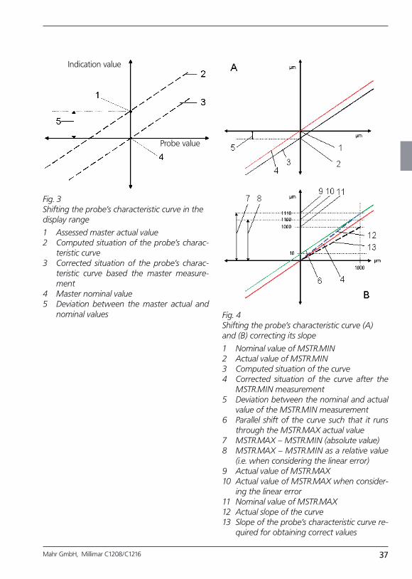
Fig. 3 Shifting the probe’s characteristic curve in the display range
1 Assessed master actual value2 Computed situation of the probe’s charac
teristic curve3 Corrected situation of the probe’s charac
teristic curve based the master measurement
4 Master nominal value5 Deviation between the master actual and
nominal values Fig. 4 Shifting the probe’s characteristic curve (A) and (B) correcting its slope
1 Nominal value of MSTR.MIN2 Actual value of MSTR.MIN3 Computed situation of the curve4 Corrected situation of the curve after the
MSTR.MIN measurement5 Deviation between the nominal and actual
value of the MSTR.MIN measurement6 Parallel shift of the curve such that it runs
through the MSTR.MAX actual value7 MSTR.MAX – MSTR.MIN (absolute value)8 MSTR.MAX – MSTR.MIN as a relative value
(i.e. when considering the linear error)9 Actual value of MSTR.MAX10 Actual value of MSTR.MAX when consider
ing the linear error11 Nominal value of MSTR.MAX12 Actual slope of the curve13 Slope of the probe’s characteristic curve re
quired for obtaining correct values
Indication value
Probe value
38 Mahr GmbH, Millimar C1208/C1216
8.1 How to select the type of master measurement
1. Press the MENU key. The catalog of func-tions and parameters item “FEATURE (1)” is displayed.
2. Repeatedly press the MASTER key until “PROCESS (3)” appears.
3. Press the MENU key again. “MEASURE (3.1)” is displayed.
4. Press the MASTER key. “MASTER (3.2)” is displayed.
5. Press the MENU key and use the DATA and MASTER keys to select either MAST 1P (3.2.1, one-point master measurement) or MAST 2P (3.2.2, two-point master measure-ment).
iThe setting "MAST 2P" can only be selected, if the channel connection (formula) "C1" or "-C1" was set before.
6. Press START to terminate the measuring method selection process and press START again to adopt the selected method.
7. If no further settings are to be made in the catalog of functions and parameters, press the START key. The standard display ele-ments appear.
If further settings are necessary, navigate to the appropriate point of the catalog of functions and parameters using the ESC, MASTER, DATA and MENU keys and carry out the settings as required.
8.2 Entering the nominal master value for a onepoint master measurement
The dimensions of master workpieces usually deviate only fractionally from the required nomi-nal size. The actual size of the master workpiece, known as the master actual value, must be en-tered in the catalog of functions and parameters prior to starting master measurement.
1. Press the MENU key. The catalog of func-tions and parameters item “FEATURE (1)” is displayed.
2. Press the MENU key again to get to the sub-menus.
3. Use the DATA and MASTER keys to select “MASTER ” and press the MENU key again. “MASTER” is displayed along with a nu-merical value that will vary depending on the measuring unit that has been selected for the display: 0.3 mm or 300 µm or 0.011811 inch.
4. Change the indicated numerical value to match the nominal value of the master (see section “Changing numerical values for pa-rameter settings” in chapter 0).
5. Once the nominal value has been set as re-quired, press the START key. This terminates the process and the set nominal value flash-es.
39Mahr GmbH, Millimar C1208/C1216
6. Press the START key again to adopt the flashing nominal value as the current setting. The display then returns to the catalog of functions and parameters item “MASTER”.
If at this point either the MASTER or DATA key is pressed instead of START, the dis-play returns to the numerical input stage (cf. point 4). The indicated nominal value can be changed again if required.
7. If no further settings are to be made in the catalog of functions and parameters, press the START key. The standard display ele-ments appear.
If further settings are necessary, navigate to the appropriate point of the catalog of functions and parameters using the ESC, MASTER, DATA and MENU keys and carry out the settings as required.
8.3 Entering the nominal master value for a twopoint master mea surement
The dimensions of master workpieces usually deviate only fractionally from the required nomi-nal size. The actual size of the master workpiece must be entered in the catalog of functions and parameters prior to starting master measure-ment.
1. Press the MENU key. The catalog of func-tions and parameters item “FEATURE (1)” is displayed.
2. Press the MENU key again.
3. Use the DATA and MASTER keys to select “MSTR.MAX”.
4. Press the MENU key again. “MSTR.MAX” is displayed along with a numerical value that will vary depending on the measuring unit that has been selected for the display: 0.3 mm or 300 µm or 0.011811 inch.
5. Change the indicated numerical value to match the nominal value of the larger of the two masters (see section “Changing numeri-cal values for parameter settings” in chapter 0).
6. Once the nominal value has been set as re-quired, press the START key. This terminates the process and the set nominal value flash-es.
40 Mahr GmbH, Millimar C1208/C1216
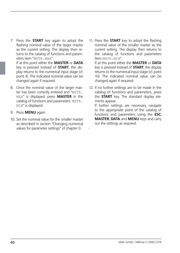
7. Press the START key again to adopt the flashing nominal value of the larger master as the current setting. The display then re-turns to the catalog of functions and param-eters item “MSTR.MAX”.
If at this point either the MASTER or DATA key is pressed instead of START, the dis-play returns to the numerical input stage (cf. point 4). The indicated nominal value can be changed again if required.
8. Once the nominal value of the larger mas-ter has been correctly entered and “MSTR.MAX” is displayed, press MASTER in the catalog of functions and parameters. MSTR.MIN” is displayed.
9. Press MENU again.
10. Set the nominal value for the smaller master as described in section “Changing numerical values for parameter settings” of chapter 0.
11. Press the START key to adopt the flashing nominal value of the smaller master as the current setting. The display then returns to the catalog of functions and parameters item MSTR.MIN”.
If at this point either the MASTER or DATA key is pressed instead of START, the display returns to the numerical input stage (cf. point 10). The indicated nominal value can be changed again if required.
12. If no further settings are to be made in the catalog of functions and parameters, press the START key. The standard display ele-ments appear.
If further settings are necessary, navigate to the appropriate point of the catalog of functions and parameters using the ESC, MASTER, DATA and MENU keys and carry out the settings as required.
.
41Mahr GmbH, Millimar C1208/C1216
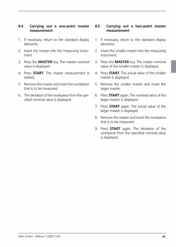
8.4 Carrying out a onepoint master measurement
1. If necessary, return to the standard display elements.
2. Insert the master into the measuring instru-ment.
3. Press the MASTER key. The master nominal value is displayed.
4. Press START. The master measurement is started.
5. Remove the master and insert the workpiece that is to be measured.
6. The deviation of the workpiece from the spe-cified nominal value is displayed.
8.5 Carrying out a twopoint master measurement
1. If necessary, return to the standard display elements.
2. Insert the smaller master into the measuring instrument.
3. Press the MASTER key. The master nominal value of the smaller master is displayed.
4. Press START. The actual value of the smaller master is displayed.
5. Remove the smaller master and insert the larger master.
6. Press START again. The nominal value of the larger master is displayed.
7. Press START again. The actual value of the larger master is displayed.
8. Remove the master and insert the workpiece that is to be measured.
9. Press START again. The deviation of the workpiece from the specified nominal value is displayed.
42 Mahr GmbH, Millimar C1208/C1216
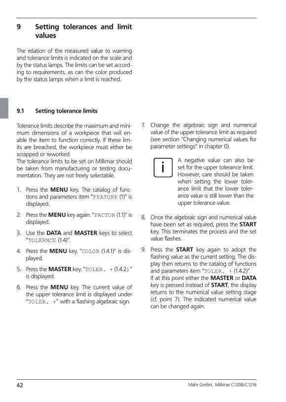
9 Setting tolerances and limit values
The relation of the measured value to warning and tolerance limits is indicated on the scale and by the status lamps. The limits can be set accord-ing to requirements, as can the color produced by the status lamps when a limit is reached.
7. Change the algebraic sign and numerical value of the upper tolerance limit as required (see section “Changing numerical values for parameter settings” in chapter 0).
iA negative value can also be set for the upper tolerance limit. However, care should be taken when setting the lower toler-ance limit that the lower toler-ance value is still lower than the upper tolerance value.
8. Once the algebraic sign and numerical value have been set as required, press the START key. This terminates the process and the set value flashes.
9. Press the START key again to adopt the flashing value as the current setting. The dis-play then returns to the catalog of functions and parameters item “TOLER. + (1.4.2)”.
If at this point either the MASTER or DATA key is pressed instead of START, the display returns to the numerical value setting stage (cf. point 7). The indicated numerical value can be changed again.
9.1 Setting tolerance limits
Tolerance limits describe the maximum and mini-mum dimensions of a workpiece that will en-able the item to function correctly. If these lim-its are breached, the workpiece must either be scrapped or reworked.The tolerance limits to be set on Millimar should be taken from manufacturing or testing docu-mentation. They are not freely selectable.
1. Press the MENU key. The catalog of func-tions and parameters item “FEATURE (1)” is displayed.
2. Press the MENU key again. “FACTOR (1.1)” is displayed.
3. Use the DATA and MASTER keys to select “TOLERNCE (1.4)”.
4. Press the MENU key. “COLOR (1.4.1)” is dis-played.
5. Press the MASTER key. “TOLER. + (1.4.2)” is displayed.
6. Press the MENU key. The current value of the upper tolerance limit is displayed under “TOLER. +” with a flashing algebraic sign.
43Mahr GmbH, Millimar C1208/C1216
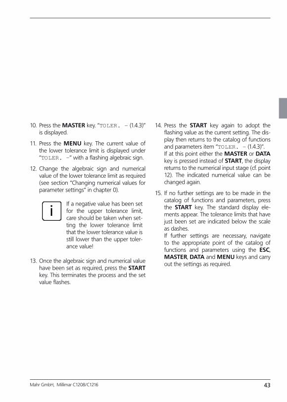
10. Press the MASTER key. “TOLER. – (1.4.3)” is displayed.
11. Press the MENU key. The current value of the lower tolerance limit is displayed under “TOLER. –” with a flashing algebraic sign.
12. Change the algebraic sign and numerical value of the lower tolerance limit as required (see section “Changing numerical values for parameter settings” in chapter 0).
iIf a negative value has been set for the upper tolerance limit, care should be taken when set-ting the lower tolerance limit that the lower tolerance value is still lower than the upper toler-ance value!
13. Once the algebraic sign and numerical value have been set as required, press the START key. This terminates the process and the set value flashes.
14. Press the START key again to adopt the flashing value as the current setting. The dis-play then returns to the catalog of functions and parameters item “TOLER. – (1.4.3)”.
If at this point either the MASTER or DATA key is pressed instead of START, the display returns to the numerical input stage (cf. point 12). The indicated numerical value can be changed again.
15. If no further settings are to be made in the catalog of functions and parameters, press the START key. The standard display ele-ments appear. The tolerance limits that have just been set are indicated below the scale as dashes.
If further settings are necessary, navigate to the appropriate point of the catalog of functions and parameters using the ESC, MASTER, DATA and MENU keys and carry out the settings as required.
44 Mahr GmbH, Millimar C1208/C1216
9.2 Setting warning limits
If tolerance limits are breached, the workpiece in question must either be reworked or, if unus-able, scrapped. To avoid this and to quickly iden-tify trends, warning limits can be set prior to the tolerance limits being reached. Although work-pieces that breach these warning limits are still usable, the repeated and successive breaching of these limits indicates that the production process must be amended to prevent items produced at a later stage from breaching tolerance limits.
1. Press the MENU key. The catalog of func-tions and parameters item “FEATURE (1)” is displayed.
2. Press the MENU key again. “FACTOR (1.1)” is displayed.
3. Use the DATA and MASTER keys to select “TOLERNCE (1.4)”.
4. Press the MENU key. “COLOR (1.4.1)” is dis-played.
5. Use the MASTER and DATA keys to select “WARN. + (1.4.4)”.
6. Press the MENU key. The current value of the upper warning limit is displayed under “WARN. +” with a flashing algebraic sign.
7. Change the algebraic sign and numerical value of the upper warning limit as required (see section “Changing numerical values for parameter settings” in chapter 0).
8. Once the algebraic sign and numerical value have been set as required, press the START key. This terminates the process and the set value flashes.
9. Press the START key again to adopt the flashing value as the current setting. The dis-play then returns to the catalog of functions and parameters item “WARN. + (1.4.4)”.
If at this point either the MASTER or DATA key is pressed instead of START, the display returns to the numerical input stage (cf. point 7). The indicated numerical value can be changed again.
10. Press the MASTER key. “WARN. – (1.4.5)” is displayed.
11. Press the MENU key. The current value of the lower warning limit is displayed under “WARN. –” with a flashing algebraic sign.
45Mahr GmbH, Millimar C1208/C1216
12. Change the algebraic sign and numerical value of the lower warning limit as required (see section “Changing numerical values for parameter settings” in chapter 0).
13. Once the algebraic sign and numerical value have been set as required, press the START key. This terminates the process and the set value flashes.
14. Press the START key again to adopt the flashing value as the current setting. The dis-play then returns to the catalog of functions and parameters item “WARN. – (1.4.5)”.
If at this point either the MASTER or DATA key is pressed instead of START, the display returns to the numerical value setting stage (cf. point 11). The indicated numerical value can be changed again.
15. If no further settings are to be made in the catalog of functions and parameters, press the START key. The standard display ele-ments appear.
If further settings are necessary, navigate to the appropriate point of the catalog of functions and parameters using the ESC, MASTER, DATA and MENU keys and carry out the settings as required.
iIn contrast to the tolerance lim-its, the warning limits are not entered on the scale. The warn-ing limits are monitored using the status lamps. The colors of the status lamps change when the entered numerical values are reached.
46 Mahr GmbH, Millimar C1208/C1216
9.3 Setting the color of the status lamps for warning and tolerance limits
The relation of a measured value to the tolerance limits is indicated on the scale by the position of the flashing indicator in relation to tolerance markings (lines underneath the scale) and by the color of the status lamps. The relation of the measured value to the warn-ing limits is indicated solely by the color of the status lamps. The user can specify the color of the status lamps when limit values are complied with, when warn-ing limits are breached and when tolerance limits are breached:
1. Press the MENU key. The catalog of func-tions and parameters item “FEATURE (1)” is displayed.
2. Press the MENU key again. “FACTOR (1.1)” is displayed.
3. Use the DATA and MASTER keys to select “TOLERNCE (1.4)”.
4. Press the MENU key. “COLOR (1.4.1)” is dis-played.
5. Press the MENU key again. “TOLER.+ (1.4.1.1)” is displayed.
6. Press the MENU key again. “>T RED+ (1.4.1.1.1)” flashes.
7. If required, press MASTER to select the set-ting “>T YELLW + (1.4.1.1.2)”.
8. Press START to adopt the selected setting. “TOLER.+ (1.4.1.1)” is displayed again.
9. Press the MASTER key. “TOLER. – (1.4.1.2)” is displayed.
10. Select the color (<T RED or <T YELLW) the status lamps should adopt when a value falls below the lower tolerance limit and adopt the selection by pressing START.
11. Press the MASTER key. “WARN.– (1.4.1.3)” is displayed.
12. Select the color (W.YELW or W.GREEN) the status lamps should adopt when a value falls below the lower warning limit or exceeds the upper warning limit and adopt the selec-tion by pressing START.
iThe color selected at this point applies for both upper and low-er warning limits. It is not pos-sible to have one color for the upper warning limit and a differ-ent color for the lower warning limit.
13. If no further settings are to be made in the catalog of functions and parameters, press the START key. The standard display ele-ments appear. The colors that are selected are immediately applied for the status lamps.
If further settings are necessary, navigate to the appropriate point of the catalog of functions and parameters using the ESC, MASTER, DATA and MENU keys and carry out the settings as required.
47Mahr GmbH, Millimar C1208/C1216
9.4 Setting plausibility limits
Plausibility limits reduce the validity range of measured values within the measuring range. On delivery, the plausibility limits are set to + 2.5 mm and – 2.5 mm. In case a probe with a mea-suring range of just ± 1 mm is used, it is recom-mended to narrow the plausibility limits to ± 1 mm, as well.
If plausibility limits are fallen short of or exceed-ed, “OVERFLW” appears on the display. This in-dicates to the operator that the measurement results are outside the measuring and palusibility range and require closer analysis.
1. Press the MENU key. The catalog of func-tions and parameters item “FEATURE (1)” is displayed.
2. Press the MENU key again. “FACTOR (1.1)” is displayed.
3. Use the DATA and MASTER keys to select “PLAUS.”.
4. Press the MENU key. “PLAUS. +” is dis-played.
5. Press the MENU key again. The current plau-sibility value is displayed under “PLAUS. +” with a flashing algebraic sign.
6. Change the algebraic sign and numerical val-ue of the upper plausibility limit as required (see section “Changing numerical values for parameter settings” in chapter 0).
A negative value can also be set for the up-per plausibility limit. However, care should be taken when setting the lower plausibility limit that the lower value is still lower than the upper value.
7. Once the algebraic sign and numerical value have been set as required, press the START key. This terminates the process and the set value flashes.
8. Press the START key again to adopt the flashing value as the current setting. The dis-play then returns to the catalog of functions and parameters item “PLAUS. +”.
If at this point either the MASTER or DATA key is pressed instead of START, the display returns to the numerical input stage (cf. point 6). The indicated numerical value can be changed again.
9. Press the MASTER key. “PLAUS. +” is dis-played.
10. Press the MENU key. The current value of the lower plausibility limit is displayed under “PLAUS. –” with a flashing algebraic sign.
11. Change the algebraic sign and numerical val-ue of the lower plausibility limit as required (see section “Changing numerical values for parameter settings” in chapter 0).
iIf a negative value has been set for the upper plausibility limit, care should be taken when set-ting the lower plausibility limit that the lower value is still lower than the upper value.!
48 Mahr GmbH, Millimar C1208/C1216
12. Once the algebraic sign and numerical value have been set as required, press the START key. This terminates the process and the set value flashes.
13. Press the START key again to adopt the flashing value as the current setting. The dis-play then returns to the catalog of functions and parameters item “PLAUS.– (1.6.2)”.
If at this point either the MASTER or DATA key is pressed instead of START, the display returns to the numerical value setting stage (cf. point 11). The indicated numerical value can be changed again.
14. If no further settings are to be made in the catalog of functions and parameters, press the START key. The standard display ele-ments appear.
If further settings are necessary, navigate to the appropriate point of the catalog of functions and parameters using the ESC, MASTER, DATA and MENU keys and carry out the settings as required.
.
10 Setting parameters for recording measured values
10.1 Setting filter parameters
The signals from the probes can be filtered to avoid interference caused by grooves or soiling on the workpiece. The limit value of the filter can be set in defined increments, whereby the larger the limit value that is set, the lower the filter ef-fect.During dynamic measurement, signal filtering is dependent on both the limit value and the rota-tional speed of the workpiece.
1. Press the MENU key. The catalog of func-tions and parameters item “FEATURE (1)” is displayed.
2. Press DATA to display “SETTING (4)”.
3. Press the MENU key. “DISPLAY (4.1)” is dis-played.
4. Press MASTER to display “FILTER(4.2)”.
5. Press the MENU key. “SAMPL/S” appears, with the numerical value flashing under-neath. The following limit values can be set for filtering :
150, 75, 50, 38, 21, 15, 10, 5, 2, 1.
6. Use the DATA and MASTER keys to set the required limit value.
7. Press START once the desired limit value has been set. The selected limit value flashes.
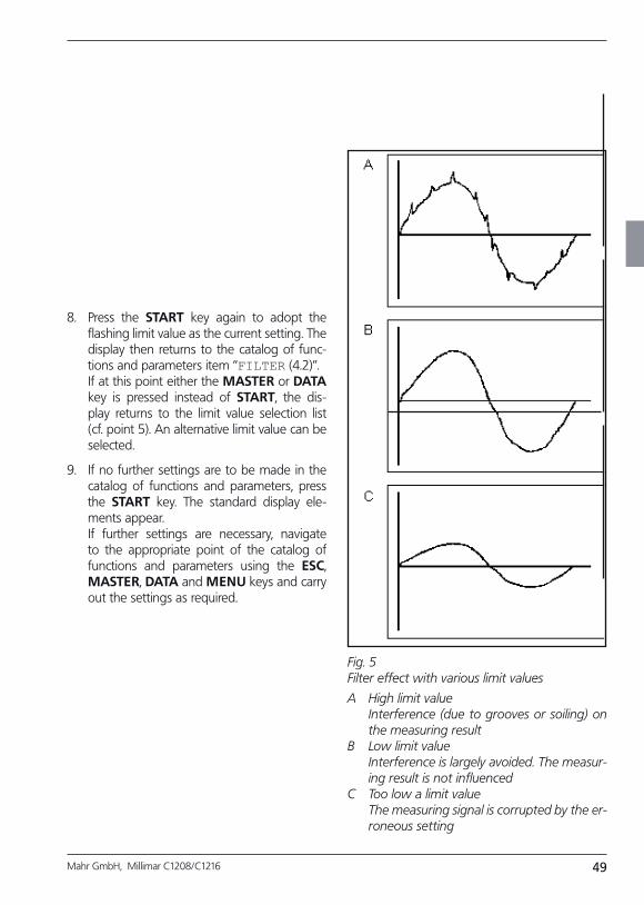
49Mahr GmbH, Millimar C1208/C1216
8. Press the START key again to adopt the flashing limit value as the current setting. The display then returns to the catalog of func-tions and parameters item “FILTER (4.2)”.
If at this point either the MASTER or DATA key is pressed instead of START, the dis-play returns to the limit value selection list (cf. point 5). An alternative limit value can be selected.
9. If no further settings are to be made in the catalog of functions and parameters, press the START key. The standard display ele-ments appear.
If further settings are necessary, navigate to the appropriate point of the catalog of functions and parameters using the ESC, MASTER, DATA and MENU keys and carry out the settings as required.
Fig. 5 Filter effect with various limit values
A High limit value Interference (due to grooves or soiling) on
the measuring resultB Low limit value Interference is largely avoided. The measur
ing result is not influencedC Too low a limit value The measuring signal is corrupted by the er
roneous setting
50 Mahr GmbH, Millimar C1208/C1216
10.2 Specifying the measuring sequence
1. Press the MENU key. The catalog of func-tions and parameters item “FEATURE (1)” is displayed.
2. Use the DATA and MASTER keys to select the setting “PROCESS (3)”.
3. Press the MENU key. “MEASURE (3.1)” is dis-played.
4. Press the MENU key. “MEAS.MOD (3.1.1)” is displayed.
5. Press the MENU key again. The current op-erating mode for workpiece measurement flashes on the display.
6. Use the DATA and MASTER keys to se-lect the “NORMAL” or “AUTOM.” operating mode. NORMAL Measurement begins when
START is pressed. On pressing START again, the MAX, MIN and MEAN value memories are de-leted.
AUTOM. A measurement is started when START is pressed. Pressing START again end the measure-ment and displays the measur-ing result. In case a time other than zero was set under “TIMER (3.1.2)”, measurement automati-cally ends after the time entered. In case a time T-PAUSE was entered under “CYCLE (3.1.3)”, measurement is resumed after the time “T-PAUSE” elapsed. The sequence of measurements and breaks is ended on pressing the START key.
Press the START key to end the sequence of single measure-ments and pauses. The "T" which is indicated in the bottom line of the display during measurement marks the "AUTOM." mode of operation.
7. Press START once the desired operating mode has been set. The selected mode now flashes.
8. Press START again to adopt the flashing operating mode. The display then returns to the catalog of functions and parameters item “MEAS.MOD (3.1.1)”.
If at this point either the MASTER or DATA key is pressed instead of START, the dis-play returns to the limit value selection list (cf. point 6). The operating mode can be changed.
9. If the operating mode “NORMAL” has been selected, skip to point 20.
If the operating mode “AUTOM.” has been selected, continue with point 10.
10. Press the MASTER key. “TIMER (3.1.2)” is displayed.
11. Press the MENU key. “T-TIMER” and the numerical value, the first digit of which flash-es, appear.
12. Enter the measurement period in seconds as required (see section “Changing numerical values for parameter settings” in chapter 0).
13. Press START once the measurement period has been entered. This terminates the pro-cess and the set value flashes.
51Mahr GmbH, Millimar C1208/C1216
14. Press START again to adopt the flashing measurement period. The display then re-turns to the catalog of functions and param-eters item “TIMER (3.1.2)”.
If at this point either the MASTER or DATA key is pressed instead of START, the display returns to the numerical input stage (cf. point 12). An alternative measurement period can be selected.
15. Press the MASTER key. “CYCLE (3.1.3)” is displayed.
16. Press the MENU key. “T-PAUSE” and the numerical value, the first digit of which flash-es, appear.
17. Enter the duration of the pause period in seconds as required (see section “Changing numerical values for parameter settings” in chapter 0).
18. Press START once the pause period has been entered. This terminates the process and the set pause period flashes.
19. Press START again to adopt the flashing pause period. The display then returns to the catalog of functions and parameters item “CYCLE (3.1.3)”.
If at this point either the MASTER or DATA key is pressed instead of START, the display returns to the numerical input stage (cf. point 17). An alternative pause period can be en-tered.
20. If no further settings are to be made in the catalog of functions and parameters, press the START key. The standard display ele-ments appear.
iOnce the standard display ele-ments appear, a measurement or measuring series can be initi-ated by pressing START. If the operating mode “AUTOM.” has been selected, “MEASURE” is displayed during measurement and “PAUSE” during the pause between measurements. If the measuring series is terminated by pressing START, “ABORT” appears briefly on the display.Please also read the notes in the following chapters relating to the operating modes “NORMAL” and “AUTOM.”.
If further settings are necessary, navigate to the appropriate point of the catalog of functions and parameters using the ESC, MASTER, DATA and MENU keys and carry out the settings as required.
52 Mahr GmbH, Millimar C1208/C1216
10.3 Operating mode “NORMAL“
iFor instructions on how to activate this mode, see chapter 10.2.
The feature is continuously calculated based on the connection formula and the function (MAXIMUM, MINIMUM, MAX+MIN, MAX-MIN, MEANVAL or NORMAL) selected. Pressing START saves the calculated value. START is also used to initiate a new measurement and recalculate the selected feature.
If the setting “NORMAL” has been selected both under “FEATURE --> FNCTION” and “PROCESS --> MEASURE --> MEAS.MOD”, it is always the current measured value that is displayed.
If the setting “MAXIMUM” has been selected under “FEATURE --> FNCTION” and the set-ting “NORMAL” under “PROCESS --> MEASURE -> MEAS.MOD”, the calculated maximum value is displayed. However, the display only changes when a new maximum value has been calcu-lated, or when the previous maximum value has been saved by pressing START and a new mea-surement initiated.
If the setting “MINIMUM” has been selected under “FEATURE --> FNCTION” and the set-ting “NORMAL” under “PROCESS --> MEASURE --> MEAS.MOD”, the calculated minimum value is displayed. However, the display only changes when a new minimum value has been calcu-lated, or when the previous minimum value has been saved by pressing START and a new mea-surement initiated.
If one of the settings “MAX+MIN”, “MAX-MIN” or “MEANVAL.” has been selected under “FEATURE --> FNCTION” and the setting “NORMAL” has been selected under “PROCESS --> MEASURE --> MEAS.MOD”, the calculated aggregate, dif-ference, or mean value is continuously updated. Pressing START saves the current value. A new measurement is then immediately started.
10.4 Operating mode “AUTOM.“
iFor instructions on how to activate this mode, see chapter 10.2.
“MEASURE” is displayed during the set measure-ment period (T-TIMER) and “PAUSE” during the pause between measurements.
At the end of the measurement period, the se-lected feature (MAXIMUM, MINIMUM, MAX+MIN, MAX-MIN or MEANVAL) is calculated and dis-played for the pause period. If “NORMAL” has been selected under “FEATURE à FNCTION”, the previously calculated measured value is displayed at the end of the measure-ment period.
At the end of the pause period, the next mea-surement starts. The pause/measurement se-quence continues until either the START key is pressed or the catalog of functions and param-eters is opened with the MENU key.
53Mahr GmbH, Millimar C1208/C1216
10.5 Entering a start delay
If a period of delay is required between pressing the START key and actually initiating measure-ment, a period of time can be entered by which the start of measurement can be put back. A start delay is most useful when performing a dynamic measurement (e.g. of a shaft) and the measurement is to be started automatically via a switching contact in the measuring device. The startup of the shaft causes oscillation in the mea-suring instrument that can influence the mea-suring result. During the delay period, which is indicated by “WAIT”, the oscillation subsides and ceases to affect the measuring result.
1. Press the MENU key. The catalog of func-tions and parameters item “FEATURE (1)” is displayed.
2. Use the DATA and MASTER keys to select the setting “PROCESS (3)”.
3. Press the MENU key. “MEASURE (3.1)” is dis-played.
4. Press MENU again “MEAS.MOD (3.1.1)” is displayed.
5. Use the DATA and MASTER keys to select the setting “DELAY (3.1.4)”.
6. Press the MENU key. “DELAY” is displayed with a numerical value underneath, the first digit of which flashes.
7. Enter the duration of the start delay period in seconds (see section “Changing numerical values for parameter settings” in chapter 0).
8. Press START once the delay period has been entered. This terminates the process and the set delay period flashes.
9. Press START again to adopt the flashing de-lay period. The display then returns to the catalog of functions and parameters item “DELAY (3.1.4)”.
10. If no further settings are to be made in the catalog of functions and parameters, press the START key. The standard display ele-ments appear.
If further settings are necessary, navigate to the appropriate point of the catalog of functions and parameters using the ESC, MASTER, DATA and MENU keys and carry out the settings as required.
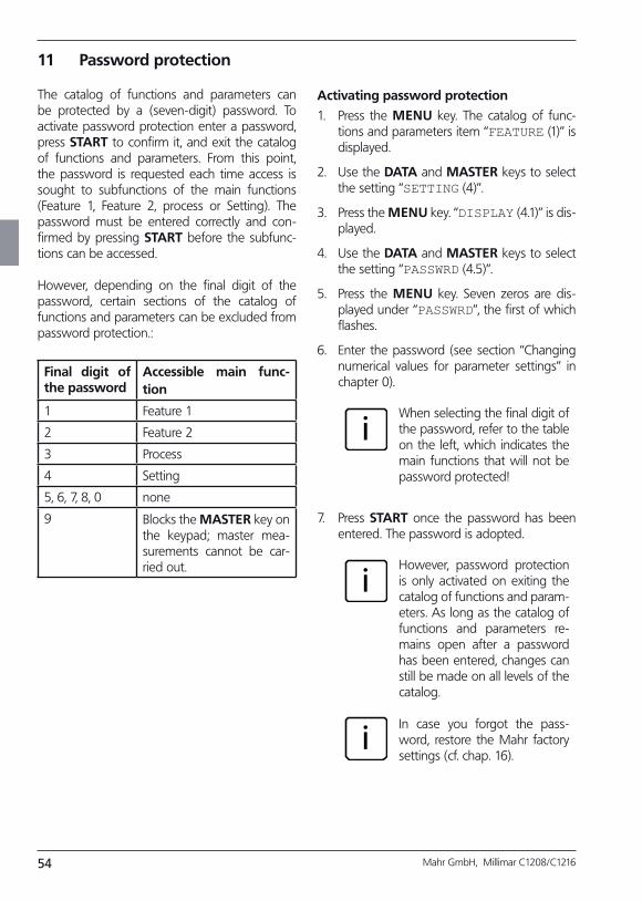
54 Mahr GmbH, Millimar C1208/C1216
11 Password protection
The catalog of functions and parameters can be protected by a (seven-digit) password. To activate password protection enter a password, press START to confirm it, and exit the catalog of functions and parameters. From this point, the password is requested each time access is sought to subfunctions of the main functions (Feature 1, Feature 2, process or Setting). The password must be entered correctly and con-firmed by pressing START before the subfunc-tions can be accessed.
However, depending on the final digit of the password, certain sections of the catalog of functions and parameters can be excluded from password protection.:
Final digit of the password
Accessible main function
1 Feature 1
2 Feature 2
3 Process
4 Setting
5, 6, 7, 8, 0 none
9 Blocks the MASTER key on the keypad; master mea-surements cannot be car-ried out.
Activating password protection
1. Press the MENU key. The catalog of func-tions and parameters item “FEATURE (1)” is displayed.
2. Use the DATA and MASTER keys to select the setting “SETTING (4)”.
3. Press the MENU key. “DISPLAY (4.1)” is dis-played.
4. Use the DATA and MASTER keys to select the setting “PASSWRD (4.5)”.
5. Press the MENU key. Seven zeros are dis-played under “PASSWRD”, the first of which flashes.
6. Enter the password (see section “Changing numerical values for parameter settings” in chapter 0).
iWhen selecting the final digit of the password, refer to the table on the left, which indicates the main functions that will not be password protected!
7. Press START once the password has been entered. The password is adopted.
i
i
However, password protection is only activated on exiting the catalog of functions and param-eters. As long as the catalog of functions and parameters re-mains open after a password has been entered, changes can still be made on all levels of the catalog.
In case you forgot the pass-word, restore the Mahr factory settings (cf. chap. 16).

55Mahr GmbH, Millimar C1208/C1216
8. If no further settings are to be made in the catalog of functions and parameters, press the START key. The standard display ele-ments appear.
If further settings are necessary, navigate to the appropriate point of the catalog of functions and parameters using the ESC, MASTER, DATA and MENU keys and carry out the settings as required.
12 Performing measurements
BWhen taking measurements and evaluating results, the polarity direction assignment of the probe must be considered. The polarity of the probe is assigned as follows:“C1” or “C2” connection formula and retracting measuring bolt ==>The numerical value increases, the pointer on the scale moves to the right. In other words, the dis-play moves in the direction of the probe.
The direction of the display can be changed as required - by selecting a formula with a negative alge-
braic sign (“-C1” or “–C2”)
- by changing the algebraic sign of the factor (-1.0 as opposed to 1.0)
iHowever, if a formula with a nega-tive algebraic sign is selected at the same time as a factor with a nega-tive algebraic sign, the direction of the display is not changed, as both negative algebraic signs cancel each other out.
Fig. 6 Signals from the measuring probe and measuring direction assignment
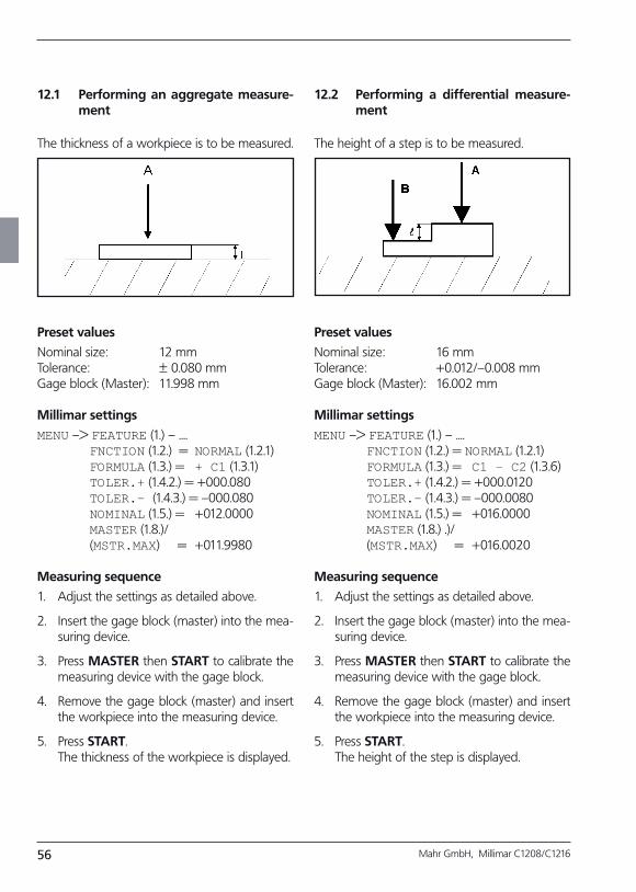
56 Mahr GmbH, Millimar C1208/C1216
12.1 Performing an aggregate measurement
The thickness of a workpiece is to be measured.
Preset values
Nominal size: 12 mmTolerance: ± 0.080 mmGage block (Master): 11.998 mm
Millimar settings
MENU –> FEATURE (1.) – .... FNCTION (1.2.) = NORMAL (1.2.1) FORMULA (1.3.) = + C1 (1.3.1) TOLER.+ (1.4.2.) = +000.080 TOLER.– (1.4.3.) = –000.080 NOMINAL (1.5.) = +012.0000 MASTER (1.8.)/ (MSTR.MAX) = +011.9980
Measuring sequence
1. Adjust the settings as detailed above.
2. Insert the gage block (master) into the mea-suring device.
3. Press MASTER then START to calibrate the measuring device with the gage block.
4. Remove the gage block (master) and insert the workpiece into the measuring device.
5. Press START. The thickness of the workpiece is displayed.
12.2 Performing a differential measurement
The height of a step is to be measured.
Preset values
Nominal size: 16 mmTolerance: +0.012/–0.008 mm Gage block (Master): 16.002 mm
Millimar settings
MENU –> FEATURE (1.) – .... FNCTION (1.2.) = NORMAL (1.2.1) FORMULA (1.3.) = C1 – C2 (1.3.6) TOLER.+ (1.4.2.) = +000.0120 TOLER.– (1.4.3.) = –000.0080 NOMINAL (1.5.) = +016.0000 MASTER (1.8.) .)/ (MSTR.MAX) = +016.0020
Measuring sequence
1. Adjust the settings as detailed above.
2. Insert the gage block (master) into the mea-suring device.
3. Press MASTER then START to calibrate the measuring device with the gage block.
4. Remove the gage block (master) and insert the workpiece into the measuring device.
5. Press START. The height of the step is displayed.
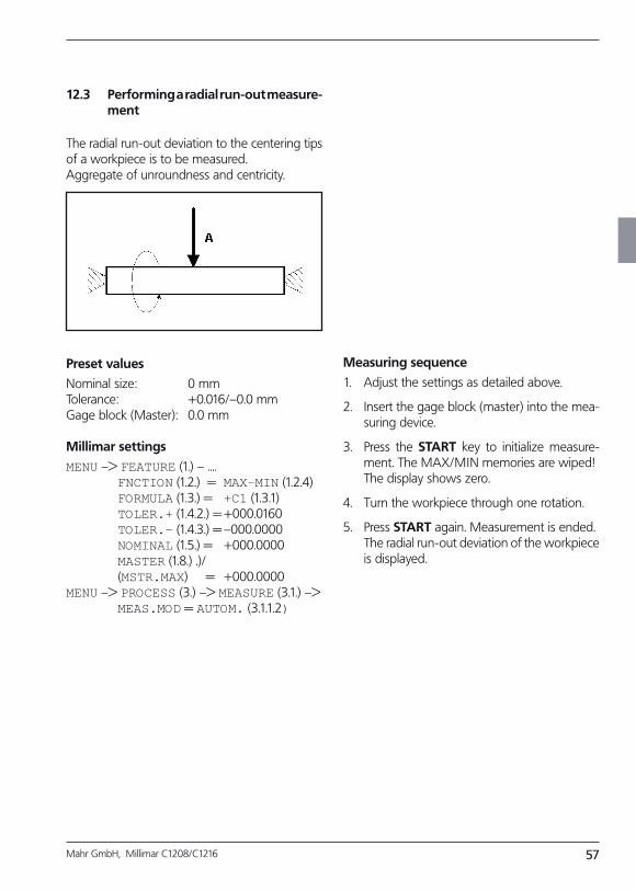
57Mahr GmbH, Millimar C1208/C1216
12.3 Performing a radial runout measurement
The radial run-out deviation to the centering tips of a workpiece is to be measured.Aggregate of unroundness and centricity.
Preset values
Nominal size: 0 mmTolerance: +0.016/–0.0 mm Gage block (Master): 0.0 mm
Millimar settings
MENU –> FEATURE (1.) – .... FNCTION (1.2.) = MAX–MIN (1.2.4) FORMULA (1.3.) = +C1 (1.3.1) TOLER.+ (1.4.2.) = +000.0160 TOLER.– (1.4.3.) = –000.0000 NOMINAL (1.5.) = +000.0000 MASTER (1.8.) .)/ (MSTR.MAX) = +000.0000 MENU –> PROCESS (3.) –> MEASURE (3.1.) –> MEAS.MOD = AUTOM. (3.1.1.2)
Measuring sequence
1. Adjust the settings as detailed above.
2. Insert the gage block (master) into the mea-suring device.
3. Press the START key to initialize measure-ment. The MAX/MIN memories are wiped!
The display shows zero.
4. Turn the workpiece through one rotation.
5. Press START again. Measurement is ended. The radial run-out deviation of the workpiece
is displayed.
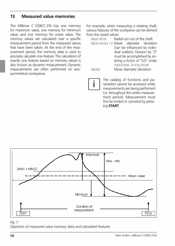
58 Mahr GmbH, Millimar C1208/C1216
13 Measured value memories
The Millimar C 1208/C 216 has one memory for maximum value, one memory for minimum value, and one memory for mean value. The memory values are calculated over a specific measurement period from the measured values that have been taken. At the end of the mea-surement period, the memory data is used to precisely calculate one feature. The calculation of exactly one feature based on memory values is also known as dynamic measurement. Dynamic measurements are often performed on axis-symmetrical workpieces.
For example, when measuring a rotating shaft, various features of the workpiece can be derived from the saved values:
MAX-MIN Radial run-out of the shaftMAX+MIN)/2 Mean diameter deviation
(can be influenced by indivi-du al outliers). Division by “2” must be accomplished by en-tering a foctor of “0.5” under FEATURE -> FACTOR!
MEAN Mean diameter deviation
iThe catalog of functions and pa-rameters cannot be accessed while measurements are being performed (i.e. throughout the entire measure-ment period). Measurement must first be ended or canceled by press-ing START.
Fig. 7 Depiction of measured value memory data and calculated features

59Mahr GmbH, Millimar C1208/C1216
Activating the measured value memory function
Select “AUTOM (3.1.1.2)” under PROCESS --> MEASURE --> MEAS.MOD. The letter “T” ap-pears in the footer of the display, indicating that the measured value memory function is active.
Controlling the measurement period for the measured value memory function
1. With the START key
When the START key is pressed for the first time, any data saved in the measured value memo-ries is deleted and the measurement period is started. The data stored in the measured value memories is continuously updated until the START key is pressed again. The measurement period ends and the desired feature is calculated from the saved data and displayed.
2. By entering a specified period of time
The measurement period during which data in the measured value memory is updated is speci-fied in seconds. The measurement period can be set under
PROCESS -> MEASURE ->TIMER (3.1.2)
between 0.1 seconds and 999.9 seconds. Measurement is started either by pressing the START key or by an appropriate signal at the control input. At the end of the measurement period, measurement ceases, i.e. the data in the measured value memories is no longer updat-ed.
3. Using a control input
The measured value storage can also be acti-vated and deactivated using control signals. This approach is suitable when e.g. the measured value memory is to be activated and deactivated using contacts that are fitted to the measuring instrument.
60 Mahr GmbH, Millimar C1208/C1216
14 Using the serial interface (RS 232)
14.1 Selecting the interface protocol
“Interface protocol” refers to the way in which different devices exchange data. As the Millimar C 1208/C 1216 can be operated with a wide range of devices (printers, computers, control devices, …), there is a broad selection of inter-face protocols available:
OFF If the interface is not required be-cause no data is to be transferred, no interface protocol should be selected.
ASCII The acquired measured values or data from the measured value memory are output by either-pressing the Millimar DATA key or at the end of the measure-ment or continuously. This in-terface protocol does not allow data transfer to be initiated by a connected PC.
OPTORSS The acquired measured values or data from the measured value memory are output either as set under "SEND" or as requested by a connected PC. Here, the unit of measurement is output along with the numerical value. This type of protocoll is especially common with handheld measur-ing devices.
OPTORSD Millimar automatically sends the measured values or data set-tings requested by a connected PC and ceases data transfer with <CR><LF> (especially common with handheld measuring de-vices).
In order to transfer data via the serial interface (RS 232), the interface has to be set (configured) to user requirements and the measuring task in question.
Appropriate settings must be used for the fol-lowing parameters:
Interface protocol (PROTOCL)
Specify whether data is to be transferred in re-sponse to a request or automatically or whether external devices should also be able to change parameter settings.
Data transfer format (FORMAT)
Specify the number of data bits and stop bits with which values should be transferred and whether a parity check should be performed.
Data flow control (HANDSHK)
Specify how data flow control should be ex-ecuted between asynchronous devices without losing data. This function specifies whether the corresponding control signals are sent via addi-tional lines parallel to the data lines, or whether the signals (embedded in the data stream) are sent over the data lines.
Transfer rate (BAUD)
Specify the rate (in bits per second) at which data is to be transferred.
Frequency of transfer (SEND)
Specify whether data is to be transferred manu-ally by pressing the DATA key or automatically at the end of the measurement or continuously.
iThe data transfer format, the data flow control and the transfer rate must be equal for both devices (partners)!.
61Mahr GmbH, Millimar C1208/C1216
M1240 Millimar automatically sends the measured values or data set-tings requested by a connected PC and ceases data transfer with <CR>.
MARTALK Enables data and settings to be queried by a connected PC and Millimar configuration to be changed using the configuration program D 1000 X or D 1000 S.
iAs long as the connected Millimar is being configured, the D 1000 S program automatically switches the Millimar’s interface protocol to MarTalk by sending a break signal to the Millimar on the reception line. As soon as the configuration is complete, the D 1000 S reinstates the interface protocol selected by the user.
When the connected PC or pro-grammable controller is switched on or off, a break signal can be unintentionally triggered and the interface protocol “MarTalk” acti-vated. However, if Millimar does not receive a valid MarTalk command within the following 2 seconds, the interface protocol set on Millimar by the user will be automatically rein-stated.
When using a terminal emula-tor (e.g. Hyperterm) a break signal can be triggered by pressing the key combination CTRL + PAUSE/BREAK. The “DTR/DSR” line is then deactivated using the pull-down menu “CALL --> SEPARAT.”
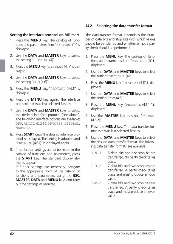
62 Mahr GmbH, Millimar C1208/C1216
Setting the interface protocol on Millimar:
1. Press the MENU key. The catalog of func-tions and parameters item “FEATURE (1)” is displayed.
2. Use the DATA and MASTER keys to select the setting “SETTING (4)”.
3. Press the MENU key. “DISPLAY (4.1)” is dis-played.
4. Use the DATA and MASTER keys to select the setting “COM (4.6)”.
5. Press the MENU key. “PROTOCL (4.6.1)” is displayed.
6. Press the MENU key again. The interface protocol that was last selected flashes.
7. Use the DATA and MASTER keys to select the desired interface protocol (see above). The following interface options are available: OFF, ASCII, M1240, OPTORSS, OPTORSD, MARTALK.
8. Press START once the desired interface pro-tocol is displayed. The setting is adopted and “PROTOCL (4.6.1)” is displayed again.
9. If no further settings are to be made in the catalog of functions and parameters, press the START key. The standard display ele-ments appear.
If further settings are necessary, navigate to the appropriate point of the catalog of functions and parameters using the ESC, MASTER, DATA and MENU keys and carry out the settings as required.
14.2 Selecting the data transfer format
The data transfer format determines the num-ber of data bits and stop bits with which values should be transferred and whether or not a par-ity check should be performed.
1. Press the MENU key. The catalog of func-tions and parameters item “FEATURE (1)” is displayed.
2. Use the DATA and MASTER keys to select the setting “SETTING (4)”.
3. Press the MENU key. “DISPLAY (4.1)” is dis-played.
4. Use the DATA and MASTER keys to select the setting “COM (4.6)”.
5. Press the MENU key. “PROTOCL (4.6.1)” is displayed.
6. Use the MASTER key to select “FORMAT (4.6.2)”.
7. Press the MENU key. The data transfer for-mat that was last selected flashes.
8. Use the DATA and MASTER keys to select the desired data transfer format. The follow-ing data transfer formats are available:
8-N-1 8 data bits and one stop bit are transferred. No parity check takes place.
7-O-2 7 data bits and two stop bits are transferred. A parity check takes place and must produce an odd value.
7-E-2 7 data bits and two stop bits are transferred. A parity check takes place and must produce an even value.
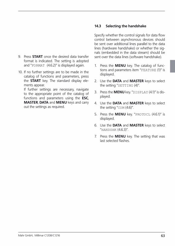
63Mahr GmbH, Millimar C1208/C1216
9. Press START once the desired data transfer format is indicated. The setting is adopted and “FORMAT (4.6.2)” is displayed again.
10. If no further settings are to be made in the catalog of functions and parameters, press the START key. The standard display ele-ments appear.
If further settings are necessary, navigate to the appropriate point of the catalog of functions and parameters using the ESC, MASTER, DATA and MENU keys and carry out the settings as required.
14.3 Selecting the handshake
Specify whether the control signals for data flow control between asynchronous devices should be sent over additional lines parallel to the data lines (hardware handshake) or whether the sig-nals (embedded in the data stream) should be sent over the data lines (software handshake).
1. Press the MENU key. The catalog of func-tions and parameters item “FEATURE (1)” is displayed.
2. Use the DATA and MASTER keys to select the setting “SETTING (4)”.
3. Press the MENU key. “DISPLAY (4.1)” is dis-played.
4. Use the DATA and MASTER keys to select the setting “COM (4.6)”.
5. Press the MENU key. “PROTOCL (4.6.1)” is displayed.
6. Use the DATA and MASTER keys to select “HANDSHK (4.6.3)”.
7. Press the MENU key. The setting that was last selected flashes.
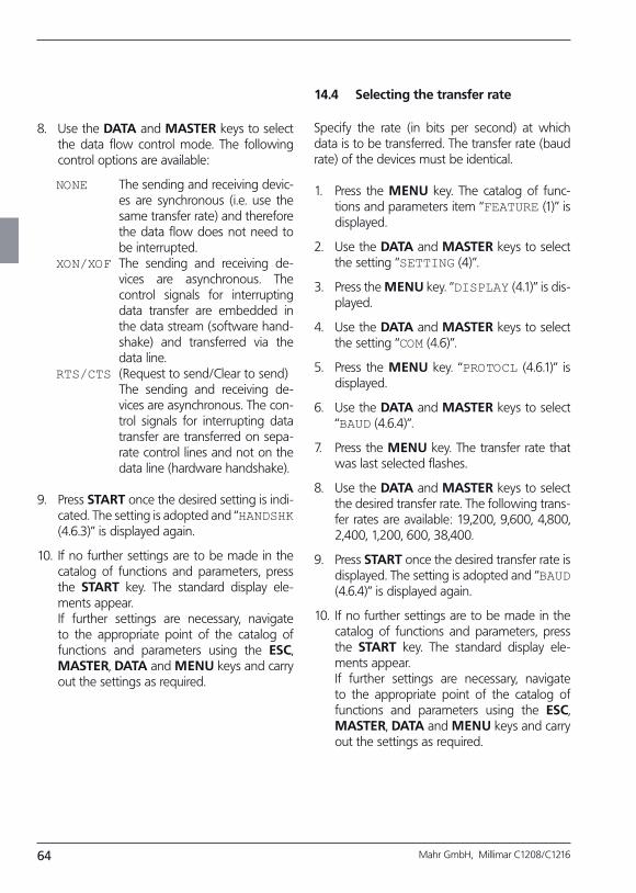
64 Mahr GmbH, Millimar C1208/C1216
8. Use the DATA and MASTER keys to select the data flow control mode. The following control options are available:
NONE The sending and receiving devic-es are synchronous (i.e. use the same transfer rate) and therefore the data flow does not need to be interrupted.
XON/XOF The sending and receiving de-vices are asynchronous. The control signals for interrupting data transfer are embedded in the data stream (software hand-shake) and transferred via the data line.
RTS/CTS (Request to send/Clear to send) The sending and receiving de-
vices are asynchronous. The con-trol signals for interrupting data transfer are transferred on sepa-rate control lines and not on the data line (hardware handshake).
9. Press START once the desired setting is indi-cated. The setting is adopted and “HANDSHK (4.6.3)” is displayed again.
10. If no further settings are to be made in the catalog of functions and parameters, press the START key. The standard display ele-ments appear.
If further settings are necessary, navigate to the appropriate point of the catalog of functions and parameters using the ESC, MASTER, DATA and MENU keys and carry out the settings as required.
14.4 Selecting the transfer rate
Specify the rate (in bits per second) at which data is to be transferred. The transfer rate (baud rate) of the devices must be identical.
1. Press the MENU key. The catalog of func-tions and parameters item “FEATURE (1)” is displayed.
2. Use the DATA and MASTER keys to select the setting “SETTING (4)”.
3. Press the MENU key. “DISPLAY (4.1)” is dis-played.
4. Use the DATA and MASTER keys to select the setting “COM (4.6)”.
5. Press the MENU key. “PROTOCL (4.6.1)” is displayed.
6. Use the DATA and MASTER keys to select “BAUD (4.6.4)”.
7. Press the MENU key. The transfer rate that was last selected flashes.
8. Use the DATA and MASTER keys to select the desired transfer rate. The following trans-fer rates are available: 19,200, 9,600, 4,800, 2,400, 1,200, 600, 38,400.
9. Press START once the desired transfer rate is displayed. The setting is adopted and “BAUD (4.6.4)” is displayed again.
10. If no further settings are to be made in the catalog of functions and parameters, press the START key. The standard display ele-ments appear.
If further settings are necessary, navigate to the appropriate point of the catalog of functions and parameters using the ESC, MASTER, DATA and MENU keys and carry out the settings as required.
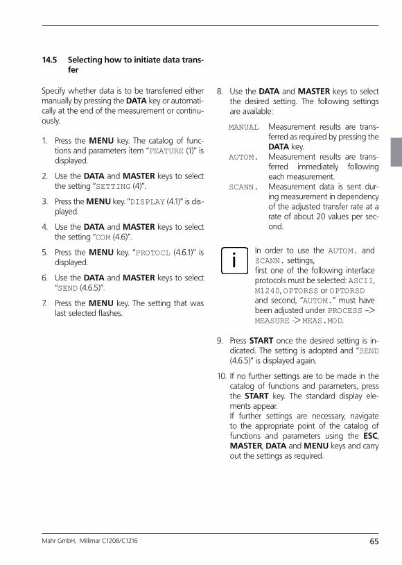
65Mahr GmbH, Millimar C1208/C1216
14.5 Selecting how to initiate data transfer
Specify whether data is to be transferred either manually by pressing the DATA key or automati-cally at the end of the measurement or continu-ously.
1. Press the MENU key. The catalog of func-tions and parameters item “FEATURE (1)” is displayed.
2. Use the DATA and MASTER keys to select the setting “SETTING (4)”.
3. Press the MENU key. “DISPLAY (4.1)” is dis-played.
4. Use the DATA and MASTER keys to select the setting “COM (4.6)”.
5. Press the MENU key. “PROTOCL (4.6.1)” is displayed.
6. Use the DATA and MASTER keys to select “SEND (4.6.5)”.
7. Press the MENU key. The setting that was last selected flashes.
8. Use the DATA and MASTER keys to select the desired setting. The following settings are available:
MANUAL Measurement results are trans-ferred as required by pressing the DATA key.
AUTOM. Measurement results are trans-ferred immediately following each measurement.
SCANN. Measurement data is sent dur-ing measurement in dependency of the adjusted transfer rate at a rate of about 20 values per sec-ond.
iIn order to use the AUTOM. and SCANN. settings, first one of the following interface protocols must be selected: ASCII, M1240, OPTORSS or OPTORSDand second, “AUTOM.” must have been adjusted under PROCESS –> MEASURE -> MEAS.MOD.
9. Press START once the desired setting is in-dicated. The setting is adopted and “SEND (4.6.5)” is displayed again.
10. If no further settings are to be made in the catalog of functions and parameters, press the START key. The standard display ele-ments appear.
If further settings are necessary, navigate to the appropriate point of the catalog of functions and parameters using the ESC, MASTER, DATA and MENU keys and carry out the settings as required.
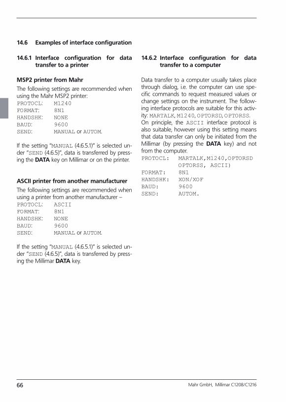
66 Mahr GmbH, Millimar C1208/C1216
14.6 Examples of interface configuration
14.6.2 Interface configuration for data transfer to a computer
Data transfer to a computer usually takes place through dialog, i.e. the computer can use spe-cific commands to request measured values or change settings on the instrument. The follow-ing interface protocols are suitable for this activ-ity: MARTALK, M1240, OPTORSD, OPTORSS. On principle, the ASCII interface protocol is also suitable, however using this setting means that data transfer can only be initiated from the Millimar (by pressing the DATA key) and not from the computer.PROTOCL: MARTALK,M1240,OPTORSD OPTORSS, ASCII)FORMAT: 8N1HANDSHK: XON/XOFBAUD: 9600SEND: AUTOM.
14.6.1 Interface configuration for data transfer to a printer
MSP2 printer from Mahr
The following settings are recommended when using the Mahr MSP2 printer:PROTOCL: M1240FORMAT: 8N1HANDSHK: NONEBAUD: 9600SEND: MANUAL or AUTOM.
If the setting “MANUAL (4.6.5.1)” is selected un-der “SEND (4.6.5)”, data is transferred by press-ing the DATA key on Millimar or on the printer.
ASCII printer from another manufacturer
The following settings are recommended when using a printer from another manufacturer –PROTOCL: ASCIIFORMAT: 8N1HANDSHK: NONEBAUD: 9600SEND: MANUAL or AUTOM.
If the setting “MANUAL (4.6.5.1)” is selected un-der “SEND (4.6.5)”, data is transferred by press-ing the Millimar DATA key.
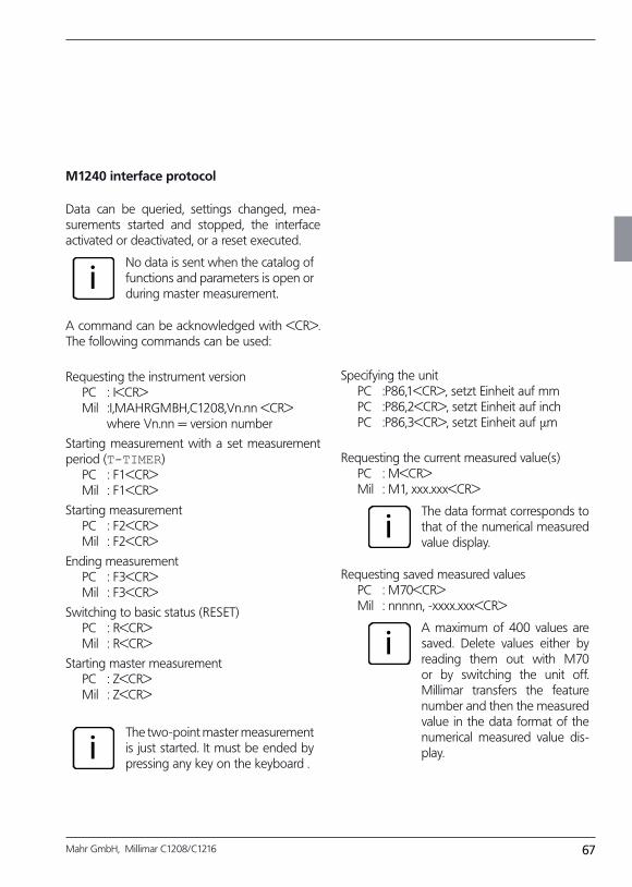
67Mahr GmbH, Millimar C1208/C1216
M1240 interface protocol
Data can be queried, settings changed, mea-surements started and stopped, the interface activated or deactivated, or a reset executed.
iNo data is sent when the catalog of functions and parameters is open or during master measurement.
A command can be acknowledged with <CR>. The following commands can be used:
Requesting the instrument version PC : I<CR> Mil :I,MAHRGMBH,C1208,Vn.nn <CR> where Vn.nn = version number
Starting measurement with a set measurement period (T-TIMER) PC : F1<CR> Mil : F1<CR>
Starting measurement PC : F2<CR> Mil : F2<CR>
Ending measurement PC : F3<CR> Mil : F3<CR>
Switching to basic status (RESET) PC : R<CR> Mil : R<CR>
Starting master measurement PC : Z<CR> Mil : Z<CR>
iThe two-point master measurement is just started. It must be ended by pressing any key on the keyboard .
Specifying the unit PC :P86,1<CR>, setzt Einheit auf mm PC :P86,2<CR>, setzt Einheit auf inch PC :P86,3<CR>, setzt Einheit auf µm
Requesting the current measured value(s) PC : M<CR> Mil : M1, xxx.xxx<CR>
iThe data format corresponds to that of the numerical measured value display.
Requesting saved measured values PC : M70<CR> Mil : nnnnn, -xxxx.xxx<CR>
iA maximum of 400 values are saved. Delete values either by reading them out with M70 or by switching the unit off. Millimar transfers the feature number and then the measured value in the data format of the numerical measured value dis-play.
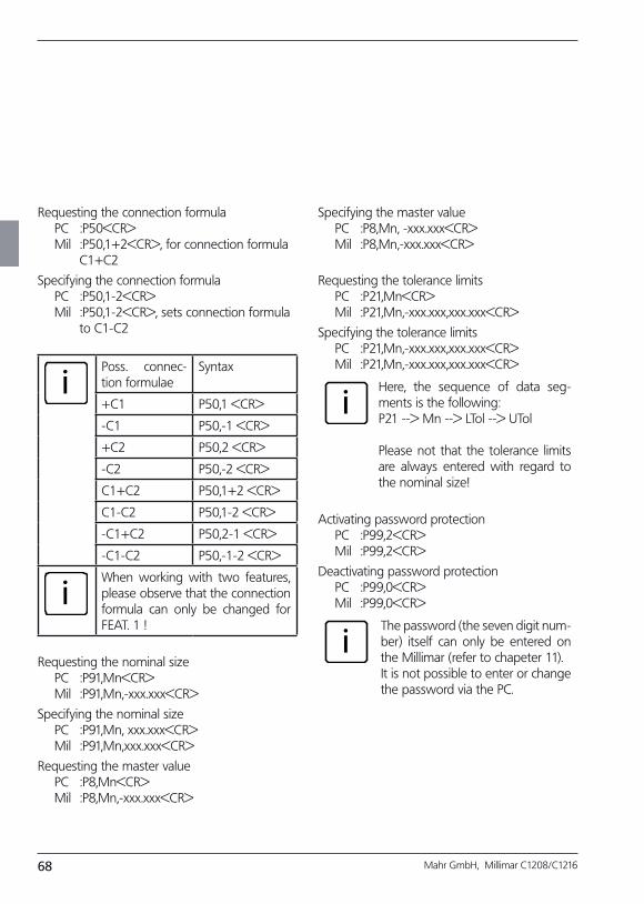
68 Mahr GmbH, Millimar C1208/C1216
Requesting the connection formula PC :P50<CR> Mil :P50,1+2<CR>, for connection formula C1+C2
Specifying the connection formula PC :P50,1-2<CR> Mil :P50,1-2<CR>, sets connection formula to C1-C2
iPoss. connec-tion formulae
Syntax
+C1 P50,1 <CR>
-C1 P50,-1 <CR>
+C2 P50,2 <CR>
-C2 P50,-2 <CR>
C1+C2 P50,1+2 <CR>
C1-C2 P50,1-2 <CR>
-C1+C2 P50,2-1 <CR>
-C1-C2 P50,-1-2 <CR>
iWhen working with two features, please observe that the connection formula can only be changed for FEAT. 1 !
Requesting the nominal size PC :P91,Mn<CR> Mil :P91,Mn,-xxx.xxx<CR>
Specifying the nominal size PC :P91,Mn, xxx.xxx<CR> Mil :P91,Mn,xxx.xxx<CR>
Requesting the master value PC :P8,Mn<CR> Mil :P8,Mn,-xxx.xxx<CR>
Specifying the master value PC :P8,Mn, -xxx.xxx<CR> Mil :P8,Mn,-xxx.xxx<CR>
Requesting the tolerance limits PC :P21,Mn<CR> Mil :P21,Mn,-xxx.xxx,xxx.xxx<CR>
Specifying the tolerance limits PC :P21,Mn,-xxx.xxx,xxx.xxx<CR> Mil :P21,Mn,-xxx.xxx,xxx.xxx<CR>
iHere, the sequence of data seg-ments is the following:P21 --> Mn --> LTol --> UTol
Please not that the tolerance limits are always entered with regard to the nominal size!
Activating password protection PC :P99,2<CR> Mil :P99,2<CR>
Deactivating password protection PC :P99,0<CR> Mil :P99,0<CR>
iThe password (the seven digit num-ber) itself can only be entered on the Millimar (refer to chapeter 11). It is not possible to enter or change the password via the PC.
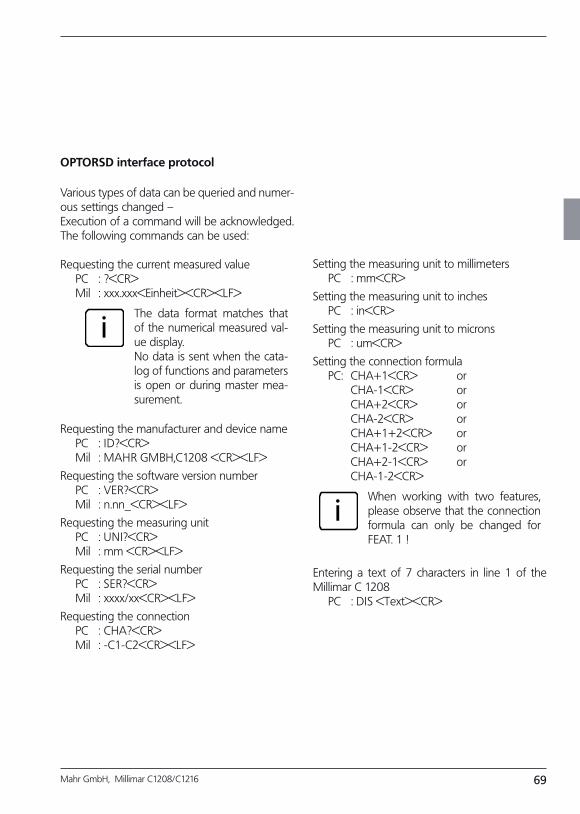
69Mahr GmbH, Millimar C1208/C1216
OPTORSD interface protocol
Various types of data can be queried and numer-ous settings changed –Execution of a command will be acknowledged. The following commands can be used:
Requesting the current measured value PC : ?<CR> Mil : xxx.xxx<Einheit><CR><LF>
iThe data format matches that of the numerical measured val-ue display.No data is sent when the cata-log of functions and parameters is open or during master mea-surement.
Requesting the manufacturer and device name PC : ID?<CR> Mil : MAHR GMBH,C1208 <CR><LF>
Requesting the software version number PC : VER?<CR> Mil : n.nn_<CR><LF>
Requesting the measuring unit PC : UNI?<CR> Mil : mm <CR><LF>
Requesting the serial number PC : SER?<CR> Mil : xxxx/xx<CR><LF>
Requesting the connection PC : CHA?<CR> Mil : -C1-C2<CR><LF>
Setting the measuring unit to millimeters PC : mm<CR>
Setting the measuring unit to inches PC : in<CR>
Setting the measuring unit to microns PC : um<CR>
Setting the connection formula PC: CHA+1<CR> or CHA-1<CR> or CHA+2<CR> or CHA-2<CR> or CHA+1+2<CR> or CHA+1-2<CR> or CHA+2-1<CR> or CHA-1-2<CR>
iWhen working with two features, please observe that the connection formula can only be changed for FEAT. 1 !
Entering a text of 7 characters in line 1 of the Millimar C 1208 PC : DIS <Text><CR>
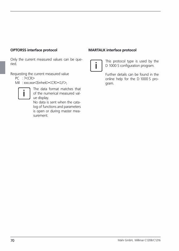
70 Mahr GmbH, Millimar C1208/C1216
OPTORSS interface protocol
Only the current measured values can be que-ried.
Requesting the current measured value PC : ?<CR> Mil : xxx.xxx<Einheit><CR><LF>,
iThe data format matches that of the numerical measured val-ue display.No data is sent when the cata-log of functions and parameters is open or during master mea-surement.
MARTALK interface protocol
iThis protocol type is used by the D 1000 S configuration program.
Further details can be found in the online help for the D 1000 S pro-gram.
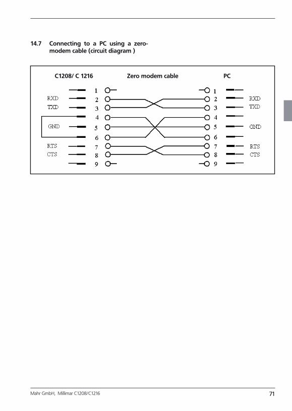
71Mahr GmbH, Millimar C1208/C1216
14.7 Connecting to a PC using a zeromodem cable (circuit diagram )
C1208/ C 1216 Zero modem cable PC

72 Mahr GmbH, Millimar C1208/C1216
* only C 1216 instruments=
15 Using the parallel (I/O) interface
A wide range of devices can be connected to the 25-pin interface – programmable controllers, displays, footswitches, recording instruments, ... Connectable devices can either control Millimar functions or be controlled by Millimar. The Millimar can also be used purely for data storage or output. Millimar has three digital control in-puts, three digital control outputs, and (Millimar C 1216 only!) one analog output to allow the in-strument to be connected to such devices.
The 3 Millimar digital control outputs can be used to output signals (e.g. when tolerance limits are exceeded) to control units or external displays. The function/significance of the 3 output signals can be adapted to suit the measuring task using several modes (0, 1, 2, 3, 4, 5).
The 3 digital control inputs enable various Millimar functions to be activated. The alloca-tion of the 3 inputs to specific functions can be adapted to suit to the measuring task using sev-eral modes (0, 1, 2, 3, 4).
If the digital control inputs and outputs are not needed, MODE 0 should be selected in each case.
Recording instruments, devices with analog/digi-tal converters or control units with analog input can be connected via the analog output (C 1216 only!).
Pin assignment of the interface
Pin Desig. Function
1 — do not assign
2 — do not assign
3 — do not assign
4 GND Ground connection
5 IN-3 opt. input E3 (+)
6 IN-3 opt. input E3 (-)
7 Vout Internal power supply+9 V, max. 100 mA
8 IN-2 opt. input E2 (+)
9 IN-2 opt. input E2 (-)
10 — not assigned
11 IN-1 opt. input E1 (+)
12 IN-1 opt. input E1 (-)
13 Analog out analog output*
14 AGND anlalog ground
15 — not assigned
16 — not assigned
17 — not assigned
18 — not assigned
19 — not assigned
20 OUT-3 opt. output A3 (+)
21 OUT-3 opt. output A3 (-)
22 OUT-2 opt. output A2 (+)
23 OUT-2 opt. output A2 (-)
24 OUT-1 opt. output A1 (+)
25 OUT-1 opt. output A1 (-)
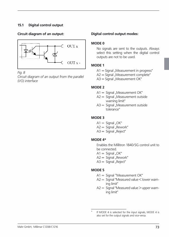
73Mahr GmbH, Millimar C1208/C1216
15.1 Digital control output
Circuit diagram of an output: Digital control output modes:
MODE 0
No signals are sent to the outputs. Always select this setting when the digital control outputs are not to be used.
MODE 1
A1 = Signal „Measurement in progress“ A2 = Signal „Measurement complete“ A3 = Signal „Measurement OK“
MODE 2
A1 = Signal „Measurement OK“ A2 = Signal „Measurement outside warning limit“ A3 = Signal „Measurement outside tolerance“
MODE 3
A1 = Signal „OK“ A2 = Signal „Rework“ A3 = Signal „Reject“
MODE 4*
Enables the Millitron 1840/SG control unit to be connected.
A1 = Signal „OK“ A2 = Signal „Rework“ A3 = Signal „Reject“
MODE 5
A1 = Signal "Measurement OK” A2 = Signal “Measured value < lower warn-
ing limit” A2 = Signal “Measured value > upper warn-
ing limit”
Fig. 8 Circuit diagram of an output from the parallel (I/O) interface
* If MODE 4 is selected for the input signals, MODE 4 is also set for the output signals and vice-versa.
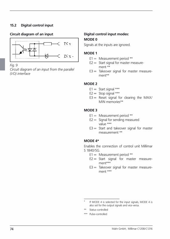
74 Mahr GmbH, Millimar C1208/C1216
15.2 Digital control input
Circuit diagram of an input Digital control input modes:
MODE 0
Signals at the inputs are ignored.
MODE 1
E1 = Measurement period ** E2 = Start signal for master measure- ment ** E3 = Takeover signal for master measure-
ment**
MODE 2
E1 = Start signal *** E2 = Stop signal *** E3 = Reset signal for clearing the MAX/
MIN memories**
MODE 3
E1 = Measurement period ** E2 = Signal for sending measured value *** E3 = Start and takeover signal for master
measurement **
MODE 4*
Enables the connection of control unit Millimar S 1840/SG. E1 = Measurement period ** E2 = Start signal for master measure-
ment*** E3 = Takeover signal for master measure-
ment ***
Fig. 9 Circuit diagram of an input from the parallel (I/O) interface
* If MODE 4 is selected for the input signals, MODE 4 is also set for the output signals and vice-versa.
** Status-controlled
*** Pulse-controlled
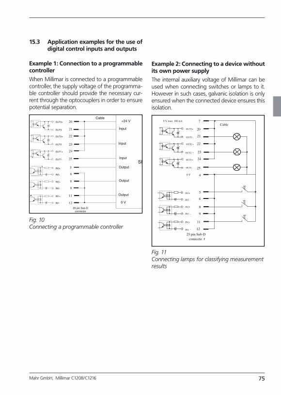
75Mahr GmbH, Millimar C1208/C1216
15.3 Application examples for the use of digital control inputs and outputs
Example 1: Connection to a programmable controller
When Millimar is connected to a programmable controller, the supply voltage of the programma-ble controller should provide the necessary cur-rent through the optocouplers in order to ensure potential separation.
Example 2: Connecting to a device without its own power supply
The internal auxiliary voltage of Millimar can be used when connecting switches or lamps to it. However in such cases, galvanic isolation is only ensured when the connected device ensures this isolation.
Fig. 10 Connecting a programmable controller
Fig. 11 Connecting lamps for classifying measurement results
20
22
23
24
21
25
5
6
8
9
11
OUT3+
OUT3-
OUT2-
OUT1-
OUT2+
OUT1+
IN3+
IN2+
IN1+
IN1-
IN2-
IN3-
Output
Output
Output
Input
Input
Input
0 V
+24 V
SPC
Cable
25 pin Sub-Dconnector
12
7
20
22
23
24
21
25
4
5
6
8
9
11
12
CableOUT3+
OUT3 -
-OUT2 -
OUT1 -
OUT2+
OUT1+
IN3+
IN2+
IN1+
IN1 -
IN2 -
IN3 -
9 V, max. 100 mA
0 V
25 pin Sub-Dconnecto r
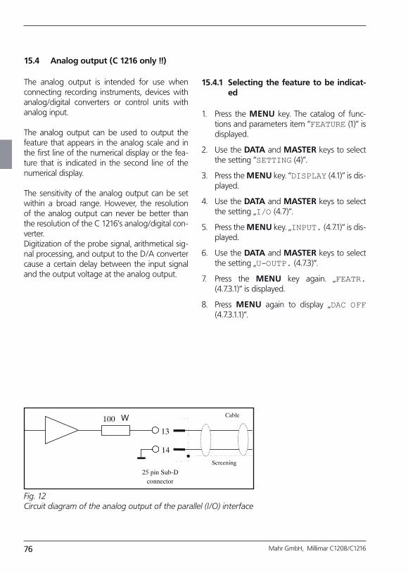
76 Mahr GmbH, Millimar C1208/C1216
15.4 Analog output (C 1216 only !!)
The analog output is intended for use when connecting recording instruments, devices with analog/digital converters or control units with analog input.
The analog output can be used to output the feature that appears in the analog scale and in the first line of the numerical display or the fea-ture that is indicated in the second line of the numerical display. The sensitivity of the analog output can be set within a broad range. However, the resolution of the analog output can never be better than the resolution of the C 1216’s analog/digital con-verter. Digitization of the probe signal, arithmetical sig-nal processing, and output to the D/A converter cause a certain delay between the input signal and the output voltage at the analog output.
Fig. 12 Circuit diagram of the analog output of the parallel (I/O) interface
15.4.1 Selecting the feature to be indicated
1. Press the MENU key. The catalog of func-tions and parameters item “FEATURE (1)” is displayed.
2. Use the DATA and MASTER keys to select the setting “SETTING (4)”.
3. Press the MENU key. “DISPLAY (4.1)” is dis-played.
4. Use the DATA and MASTER keys to select the setting „I/O (4.7)“.
5. Press the MENU key. „INPUT. (4.7.1)“ is dis-played.
6. Use the DATA and MASTER keys to select the setting „U-OUTP. (4.7.3)“.
7. Press the MENU key again. „FEATR. (4.7.3.1)“ is displayed.
8. Press MENU again to display „DAC OFF (4.7.3.1.1)“.
Cable
13
14
100 W
Screening
25 pin Sub-Dconnector
77Mahr GmbH, Millimar C1208/C1216
9. Use the DATA and MASTER keys to select the desired setting. The following settings are available:
DAC OFF No features are output via the analog output.
LINE 1 The feature indicated on the top line of the numerical measured value display will be output. This, however, is only possible if two features are indicated at the same time (see chap. 3.5)!
LINE 2 The feature indicated on the bot-tom line of the numerical mea-sured value display will be out-put.
ANALOG The feature indicated on the analog scale will be output. The output voltage depends on the deflection of the pointer on the scale.
10. Press START once the desired setting is indi-cated. The setting is adopted and „FEATR. (4.7.3.1)“ is displayed again.
11. If no further settings are to be made in the catalog of functions and parameters, press the START key. The standard display ele-ments appear.
If further settings are necessary, navigate to the appropriate point of the catalog of functions and parameters using the ESC, MASTER, DATA and MENU keys and carry out the settings as required.
78 Mahr GmbH, Millimar C1208/C1216
15.4.2 Setting the sensitivity of the analog output
1. Press the MENU key. The catalog of func-tions and parameters item “FEATURE (1)” is displayed.
2. Use the DATA and MASTER keys to select the setting “SETTING (4)”.
3. Press the MENU key. “DISPLAY (4.1)” is dis-played.
4. Use the DATA and MASTER keys to select the setting „I/O (4.7)“.
5. Press the MENU key. „INPUT. (4.7.1)“ is dis-played.
6. Use the DATA and MASTER keys to select the setting „U-OUTP. (4.7.3)“.
7. Press the MENU key again. „FEATR. (4.7.3.1)“ is displayed.
8. Press MASTER to select the setting „S FACT.(4.7.3.2)“.
9. Press the MENU key. "S FACT.“ Will be dis-played together with the value+ 00001.00.
10. Enter the sensitivity of the anlaog output as required (see section “Changing numerical values for parameter settings” in chapter 0).
iThe sensitivity value to be en-tered depends on the feature to be indicated.
DAC OFFThe entered value is of no im-portance here.
LINE 1, LINE 2The sensitivity is always speci-fied in V/m – irregardless of the adjusted unit of measurement.The numerical value to be en-tered depends on the output voltage required for a certain display value. Example for computing the numerical value: For a display value of 30 µm a voltage of 5 V is to be output: 5 V:0.03 mm = 166.667 V/mm.
ANALOGThe numerical value to be en-tered depends on the analog voltage to be output when the pointer is maximally deflected. Example: A voltage of 3V is to be output when a measured value of 100 µm is indicated in a display range of 100 µm. Sensitivity value to be entered: 3.000
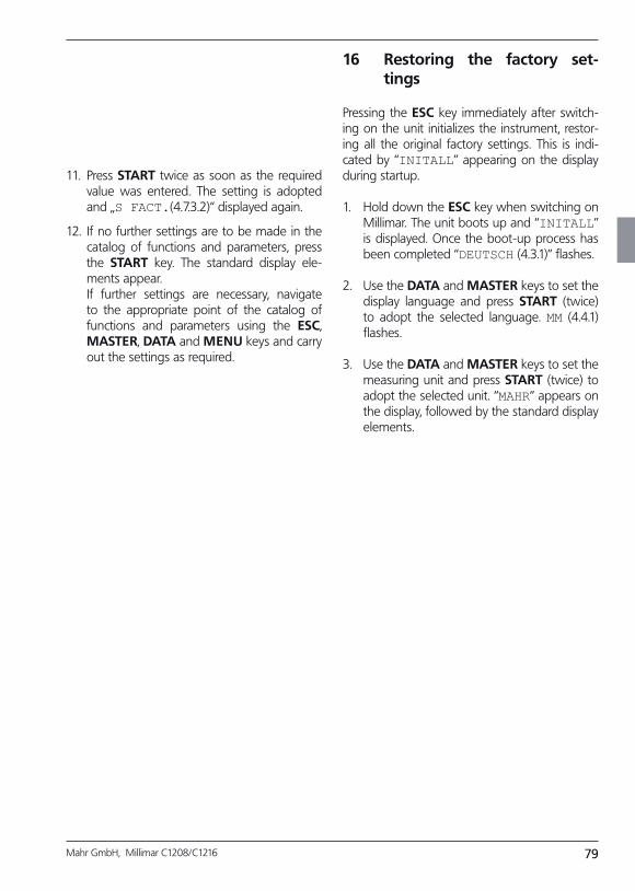
79Mahr GmbH, Millimar C1208/C1216
11. Press START twice as soon as the required value was entered. The setting is adopted and „S FACT.(4.7.3.2)“ displayed again.
12. If no further settings are to be made in the catalog of functions and parameters, press the START key. The standard display ele-ments appear.
If further settings are necessary, navigate to the appropriate point of the catalog of functions and parameters using the ESC, MASTER, DATA and MENU keys and carry out the settings as required.
16 Restoring the factory settings
Pressing the ESC key immediately after switch-ing on the unit initializes the instrument, restor-ing all the original factory settings. This is indi-cated by “INITALL” appearing on the display during startup.
1. Hold down the ESC key when switching on Millimar. The unit boots up and “INITALL” is displayed. Once the boot-up process has been completed “DEUTSCH (4.3.1)” flashes.
2. Use the DATA and MASTER keys to set the display language and press START (twice) to adopt the selected language. MM (4.4.1) flashes.
3. Use the DATA and MASTER keys to set the measuring unit and press START (twice) to adopt the selected unit. “MAHR“ appears on the display, followed by the standard display elements.

80 Mahr GmbH, Millimar C1208/C1216
17 Error messages
Error Routine Possible causes Remedy
OVFLOW Measurement The probe value exceeds the measuring or plausibility range.
Select a larger measuring or plausibility range.Correct any probe overmodulation.
OUT LIM Calibration The calculated correc-tion factor is outside the permissible range.
The specified gage blocks were not used or the di-mensions were incorrectly entered.
The nominal value selector was incorrectly set.
The probe or nominal value selector has been connect-ed to the incorrect input jack.
ERR RXD RS232 interface There is a break signal > 700 ms at the RXD input.
Check the connection be-tween the RS232 interface and external device (e.g. computer, printer, program-mable controller).
FRM FEH A two-point master mea-surement was selected even though a connec-tion formula including both probe channels is adjusted. Two-point master measure-ments are only possible if the connection formula set under “FORMULA (1.3)” reads either “C1” or “-C1”!
Adjust either “C1” or “-C1” under “FORMULA (1.3)”.
OVF LCD The number of digits to be displayed exeeds the num-ber of digits the can be indi-cated on the display.
The indication does not change even though the bolt of the probe is con-tinuously moving. The raw values in-dicated after pressing TEST, however, are OK.
Under PROCESS -> MEA-SURE -> MEAS.MOD (3.1.1), the measuring mode “AUTOM: (3.1.1.2)” was adjusted.
Adjust the “NORMAL (3.1.1.1)” measuring mode, as the case may be.
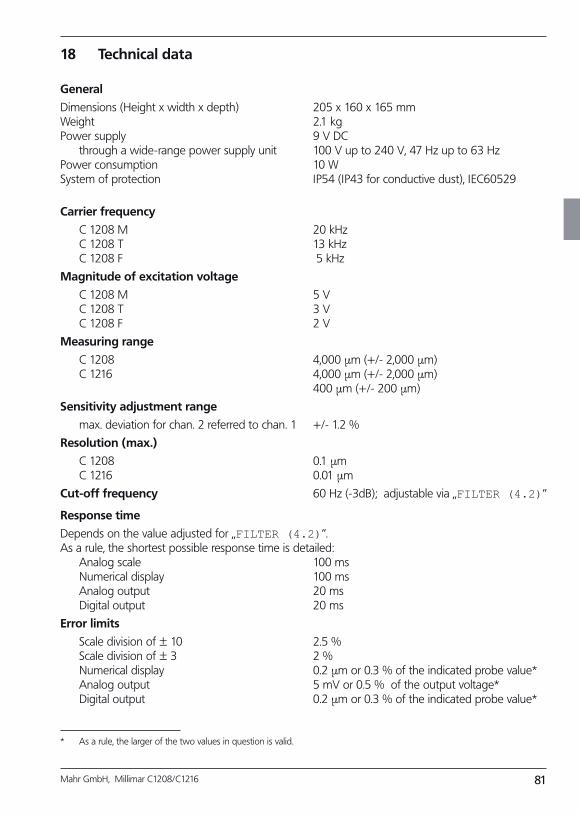
81Mahr GmbH, Millimar C1208/C1216
18 Technical data
General
Dimensions (Height x width x depth) 205 x 160 x 165 mmWeight 2.1 kgPower supply 9 V DC through a wide-range power supply unit 100 V up to 240 V, 47 Hz up to 63 HzPower consumption 10 WSystem of protection IP54 (IP43 for conductive dust), IEC60529
Carrier frequency
C 1208 M 20 kHz C 1208 T 13 kHz C 1208 F 5 kHz
Magnitude of excitation voltage
C 1208 M 5 V C 1208 T 3 V C 1208 F 2 V
Measuring range
C 1208 4,000 µm (+/- 2,000 µm) C 1216 4,000 µm (+/- 2,000 µm) 400 µm (+/- 200 µm)
Sensitivity adjustment range
max. deviation for chan. 2 referred to chan. 1 +/- 1.2 %
Resolution (max.)
C 1208 0.1 µm C 1216 0.01 µm
Cutoff frequency 60 Hz (-3dB); adjustable via „FILTER (4.2)“
Response time
Depends on the value adjusted for „FILTER (4.2)“. As a rule, the shortest possible response time is detailed: Analog scale 100 ms Numerical display 100 ms Analog output 20 ms Digital output 20 ms
Error limits
Scale division of ± 10 2.5 % Scale division of ± 3 2 % Numerical display 0.2 µm or 0.3 % of the indicated probe value* Analog output 5 mV or 0.5 % of the output voltage* Digital output 0.2 µm or 0.3 % of the indicated probe value*
* As a rule, the larger of the two values in question is valid.
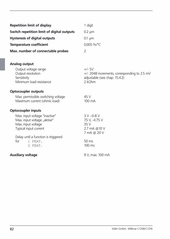
82 Mahr GmbH, Millimar C1208/C1216
Repetition limit of display 1 digit
Switch repetition limit of digital outputs 0.2 µm
Hysteresis of digital outputs 0.1 µm
Temperature coefficient 0.005 %/°C
Max. number of connectable probes 2
Analog output
Output voltage range +/- 5V Output resolution +/- 2048 increments, corresponding to 2.5 mV Sensitivity adjustable (see chap. 15.4.2) Minimum load resistance 2 kOhm
Optocoupler outputs
Max. permissible switching voltage 45 V Maximum current (ohmic load) 100 mA
Optocoupler inputs
Max. input voltage “inactive“ 3 V –0-8 V Max. input voltage „aktive“ 7.5 V, -4.75 V Max. input voltage 35 V Typical input current 2.7 mA @10 V 7 mA @ 20 V Delay until a function is triggered for 1 FEAT. 50 ms 2 FEAT. 100 ms
Auxiliary voltage 9 V, max. 100 mA
83Mahr GmbH, Millimar C1208/C1216
19 Mahr contacts
The following contacts are available to assist you:
Mahr GmbH Esslingen
Postfach 100254, D-73702 Esslingen orReutlinger Straße 48, D-73728 Esslingen
E-mail: [email protected]: (+49) 0711/9312-600Fax: (+49) 0711/9312-725
Customer Service
– for maintenance, repair, etc.
E-mail: [email protected]: (+49) 551-7073-362Fax: (+49) 551-7073-397
Customer Care Center
– Solutions for measuring tasks– Purchase of accessories– Complaints
E-mail: [email protected]: (+49) 551/7073-800Fax: (+49) 551/7073-888
20 Warranty
The unit supplied by us has been built and pro-duced with care. Before being delivered, it also un-derwent further extensive testing.
We therefore guarantee that the unit complies with the relevant safety conditions and combines sturdy construction with problem-free functionality.The duration and conditions of the warranty are set out in the general terms and conditions of delivery of Mahr GmbH or in the contract of sale.
iPlease also note the enclosed ser-vice plan with basic information on the maintenance intervals to be ob-served. Specific service intervals are to be kept to, depending on the range of applications. Proof of regular main-tenance can be one of the conditions for accepting any claims under the warranty.
Unless any other arrangements have been made, the following conditions shall apply:The warranty does not include natural wear and tear or faults arising from incorrect handling, inap-propriate use or non-observance of these operating instructions. In particular, the manufacturer can only be held liable for the function and safety features of the unit if any intervention in the unit, other than those mentioned in these operating instructions, is carried out by either the manufacturer himself or a representative expressly appointed by him.
The extreme precision of this instrument is only guaranteed when original Mahr accessories are used.
Loss of warranty:
Storage temperatures below –10 °C or above +50 °C and relative humidity lev-els above 85 % will invalidate the war-ranty for the instrument.
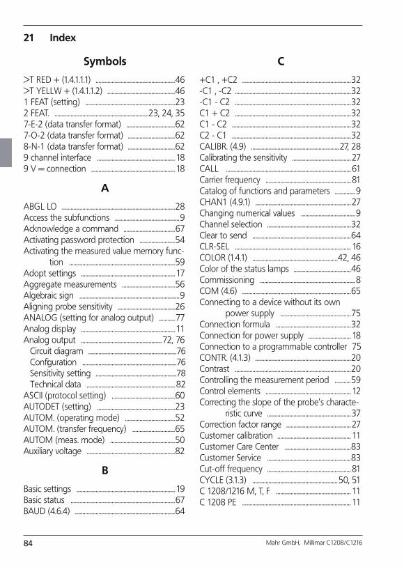
84 Mahr GmbH, Millimar C1208/C1216
Symbols
>T RED + (1.4.1.1.1) ......................................................46>T YELLW + (1.4.1.1.2) ..............................................461 FEAT (setting) .............................................................232 FEAT. ................................................................23, 24, 357-E-2 (data transfer format) .................................627-O-2 (data transfer format) ................................628-N-1 (data transfer format) ................................629 channel interface ..................................................... 189 V = connection ......................................................... 18
A
ABGL LO .............................................................................28Access the subfunctions ............................................9Acknowledge a command ...................................67Activating password protection ........................54Activating the measured value memory func-
tion ........................................................................59Adopt settings ................................................................ 17Aggregate measurements ....................................56Algebraic sign ....................................................................9Aligning probe sensitivity .......................................26ANALOG (setting for analog output) ...........77Analog display ................................................................ 11Analog output .......................................................72, 76
Circuit diagram ............................................................76Configuration ................................................................76Sensitivity setting .......................................................78Technical data ............................................................ 82
ASCII (protocol setting) ...........................................60AUTODET (setting) .....................................................23AUTOM. (operating mode) ..................................52AUTOM. (transfer frequency) .............................65AUTOM (meas. mode) ............................................50Auxiliary voltage ............................................................82
B
Basic settings ................................................................... 19Basic status .......................................................................67BAUD (4.6.4) ....................................................................64
C
+C1 , +C2 ..........................................................................32-C1 , -C2 ...............................................................................32-C1 - C2 ...............................................................................32C1 + C2 ...............................................................................32C1 - C2 .................................................................................32C2 - C1 .................................................................................32CALIBR. (4.9) ............................................................27, 28Calibrating the sensitivity ........................................27CALL ..................................................................................... 61Carrier frequency .......................................................... 81Catalog of functions and parameters ..............9CHAN1 (4.9.1) .................................................................27Changing numerical values .....................................9Channel selection .........................................................32Clear to send ...................................................................64CLR-SEL ............................................................................... 16COLOR (1.4.1) ..........................................................42, 46Color of the status lamps .......................................46Commissioning .................................................................8COM (4.6) ..........................................................................65Connecting to a device without its own
power supply ................................................75Connection formula ...................................................32Connection for power supply ............................. 18Connection to a programmable controller 75CONTR. (4.1.3) .................................................................20Contrast ...............................................................................20Controlling the measurement period ...........59Control elements .......................................................... 12Correcting the slope of the probe's characte-
ristic curve .........................................................37Correction factor range ............................................27Customer calibration .................................................. 11Customer Care Center .............................................83Customer Service .........................................................83Cut-off frequency ......................................................... 81CYCLE (3.1.3) ..........................................................50, 51C 1208/1216 M, T, F ................................................... 11C 1208 PE .......................................................................... 11
21 Index
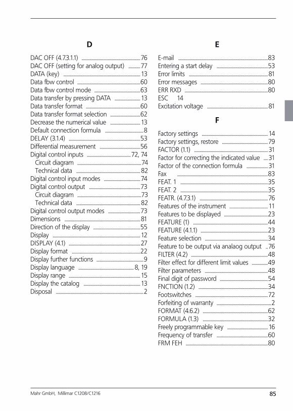
85Mahr GmbH, Millimar C1208/C1216
D
DAC OFF (4.7.3.1.1) .......................................................76DAC OFF (setting for analog output) ...........77DATA (key) ........................................................................ 13Data flow control ...........................................................60Data flow control mode ...........................................63Data transfer by pressing DATA ........................ 13Data transfer format ...................................................60Data transfer format selection ............................62Decrease the numerical value ............................ 13Default connection formula ....................................8DELAY (3.1.4) ...................................................................53Differential measurement ......................................56Digital control inputs .........................................72, 74
Circuit diagram ............................................................74Technical data ............................................................ 82
Digital control input modes ..................................74Digital control output ................................................73
Circuit diagram ............................................................73Technical data ............................................................ 82
Digital control output modes ..............................73Dimensions ....................................................................... 81Direction of the display ............................................55Display .................................................................................. 12DISPLAY (4.1) ...................................................................27Display format ................................................................22Display further functions ............................................9Display language .................................................... 8, 19Display range ................................................................... 15Display the catalog ..................................................... 13Disposal ..................................................................................2
E
E-mail ....................................................................................83Entering a start delay ................................................53Error limits .......................................................................... 81Error messages ...............................................................80ERR RXD ..............................................................................80ESC 14Excitation voltage ......................................................... 81
F
Factory settings .............................................................. 14Factory settings, restore ...........................................79FACTOR (1.1) ..................................................................... 31Factor for correcting the indicated value .... 31Factor of the connection formula .................... 31Fax .....................................................................................83FEAT. 1 ..................................................................................35FEAT. 2 ..................................................................................35FEATR. (4.7.3.1) ................................................................76Features of the instrument .................................... 11Features to be displayed .........................................23FEATURE (1) ......................................................................44FEATURE (4.1.1) ...............................................................23Feature selection ...........................................................34Feature to be output via analaog output ..76FILTER (4.2) ........................................................................48Filter effect for different limit values ...............49Filter parameters ...........................................................48Final digit of password .............................................54FNCTION (1.2) .................................................................34Footswitches ....................................................................72Forfeiting of warranty ...................................................2FORMAT (4.6.2) .............................................................62FORMULA (1.3) .............................................................32Freely programmable key ...................................... 16Frequency of transfer ................................................60FRM FEH .............................................................................80
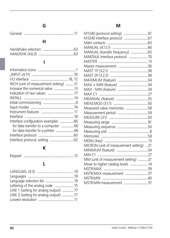
86 Mahr GmbH, Millimar C1208/C1216
G
General ................................................................................ 11
H
Handshake selection .................................................63HANDSHK (4.6.3) ........................................................63
I
Information icons ............................................................1„INPUT. (4.7.1) ...................................................................76I/O interface ............................................................ 18, 72INCH (unit of measurement setting) ............ 21Increase the numerical value ............................... 13Indication of raw values .......................................... 17INITALL ................................................................................ 14Initial commissioning ....................................................8Input modes .....................................................................74Instrument features .................................................... 11Interface .............................................................................. 18Interface configuration examples ......................66
for data transfer to a computer .................... 66for data transfer to a printer ............................ 66
Interface protocol .........................................................60Interface protocol, setting ......................................62
K
Keypad ................................................................................. 12
L
LANGUAG. (4.3) ........................................................... 19Languages ......................................................................... 19Language selection list ............................................. 19Lettering of the analog scale .............................. 15LINE 1 (setting for analog output) ..................77LINE 2 (setting for analog output) ..................77Lowest resolution ......................................................... 11
M
M1240 (protocol setting) ....................................... 61M1240 interface protocol ......................................67Mahr contacts .................................................................83MANUAL (4.1.5.1) ........................................................66MANUAL (transfer frequency) ...........................65MARTALK interface protocol ..............................70MASTER .............................................................................. 13Master measurement ...............................................36MAST 1P (3.2.1) .............................................................38MAST 2P (3.2.2) ............................................................38MAXIMUM (feature) ................................................34MAX + MIN (feature) ..............................................34MAX - MIN (feature) ................................................34MAX C1 ..............................................................................27MEANVAL (feature) ...................................................35MEAS.MOD (3.1.1) .......................................................50Measured value memories ...................................58Measurement period ................................................59MEASURE (3.1) ..............................................................50Measuring range .......................................................... 81Measuring sequence .................................................50Measuring unit ..................................................................8Memories ...........................................................................58MENU (key) ..................................................................... 13MICRON (unit of measurement setting) ... 21MINIMUM (feature) ..................................................34MIN C1 ................................................................................27MM (unit of measurement setting) ............... 21Move to higher catalog levels ............................ 14MSTR.MAX .......................................................................39MSTR.MAX measurement ....................................37MSTR.MIN .........................................................................40MSTR.MIN measurement ......................................37
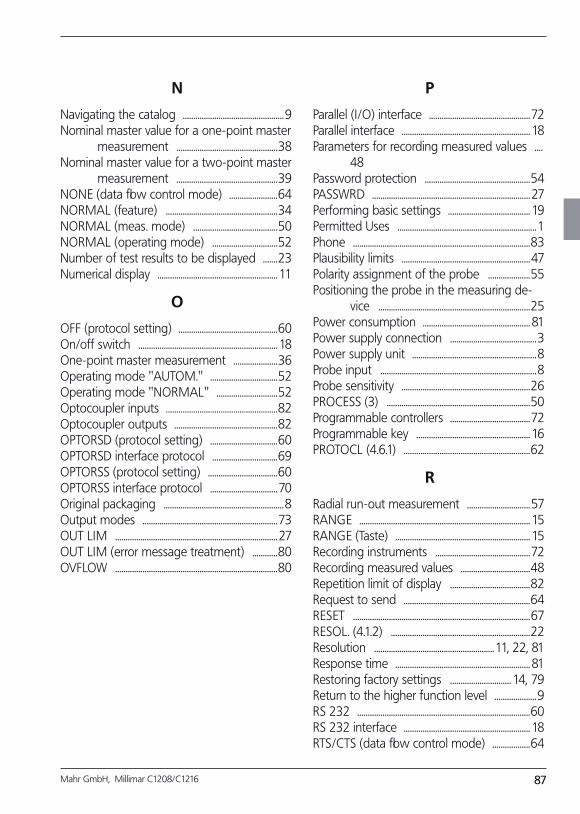
87Mahr GmbH, Millimar C1208/C1216
N
Navigating the catalog ................................................9Nominal master value for a one-point master
measurement ................................................38Nominal master value for a two-point master
mea sure ment ................................................39NONE (data flow control mode) .......................64NORMAL (feature) .....................................................34NORMAL (meas. mode) ........................................50NORMAL (operating mode) ...............................52Number of test results to be displayed .......23Numerical display ......................................................... 11
O
OFF (protocol setting) ...............................................60On/off switch .................................................................. 18One-point master measurement .....................36Operating mode "AUTOM." ................................52Operating mode "NORMAL" .............................52Optocoupler inputs .....................................................82Optocoupler outputs .................................................82OPTORSD (protocol setting) ................................60OPTORSD interface protocol ...............................69OPTORSS (protocol setting) .................................60OPTORSS interface protocol ................................70Original packaging .........................................................8Output modes ................................................................73OUT LIM .............................................................................27OUT LIM (error message treatment) ............80OVFLOW .............................................................................80
P
Parallel (I/O) interface ................................................72Parallel interface ............................................................. 18Parameters for recording measured values ....
48Password protection ..................................................54PASSWRD ...........................................................................27Performing basic settings ....................................... 19Permitted Uses ..................................................................1Phone ....................................................................................83Plausibility limits .............................................................47Polarity assignment of the probe ....................55Positioning the probe in the measuring de-
vice ........................................................................25Power consumption ................................................... 81Power supply connection .........................................3Power supply unit ...........................................................8Probe input ..........................................................................8Probe sensitivity .............................................................26PROCESS (3) ....................................................................50Programmable controllers ......................................72Programmable key ...................................................... 16PROTOCL (4.6.1) ............................................................62
R
Radial run-out measurement ..............................57RANGE ................................................................................. 15RANGE (Taste) ................................................................ 15Recording instruments .............................................72Recording measured values .................................48Repetition limit of display ......................................82Request to send ............................................................64RESET ....................................................................................67RESOL. (4.1.2) ..................................................................22Resolution .........................................................11, 22, 81Response time ................................................................ 81Restoring factory settings ............................. 14, 79Return to the higher function level ....................9RS 232 ..................................................................................60RS 232 interface ............................................................ 18RTS/CTS (data flow control mode) ..................64
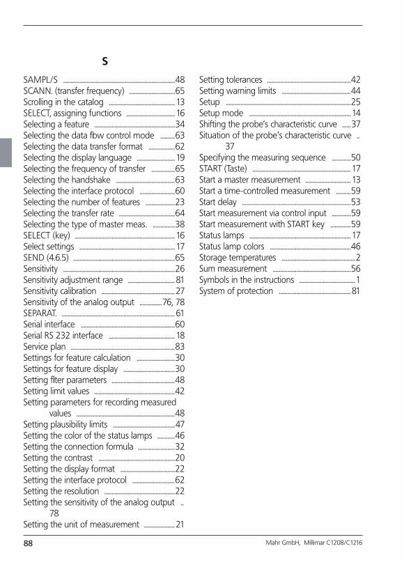
88 Mahr GmbH, Millimar C1208/C1216
S
SAMPL/S ............................................................................48SCANN. (transfer frequency) ...............................65Scrolling in the catalog ............................................. 13SELECT, assigning functions ................................. 16Selecting a feature .......................................................34Selecting the data flow control mode ..........63Selecting the data transfer format ..................62Selecting the display language .......................... 19Selecting the frequency of transfer ................65Selecting the handshake ........................................63Selecting the interface protocol ........................60Selecting the number of features ....................23Selecting the transfer rate ......................................64Selecting the type of master meas. ...............38SELECT (key) .................................................................... 16Select settings ................................................................. 17SEND (4.6.5) .....................................................................65Sensitivity ............................................................................26Sensitivity adjustment range ................................ 81Sensitivity calibration ..................................................27Sensitivity of the analog output ...............76, 78SEPARAT. ............................................................................. 61Serial interface ................................................................60Serial RS 232 interface ............................................. 18Service plan .......................................................................83Settings for feature calculation ..........................30Settings for feature display ...................................30Setting filter parameters ...........................................48Setting limit values .......................................................42Setting parameters for recor ding measured
values ...................................................................48Setting plausibility limits ..........................................47Setting the color of the status lamps ............46Setting the connection formula .........................32Setting the contrast ....................................................20Setting the display format .....................................22Setting the interface protocol .............................62Setting the resolution ................................................22Setting the sensitivity of the analog output ..
78Setting the unit of measurement ..................... 21
Setting tolerances .........................................................42Setting warning limits ...............................................44Setup .....................................................................................25Setup mode ..................................................................... 14Shifting the probe’s characteristic curve ......37Situation of the probe's characteristic curve ..
37Specifying the measuring sequence .............50START (Taste) ................................................................... 17Start a master measurement ............................... 13Start a time-controlled measurement ..........59Start delay ..........................................................................53Start measurement via control input .............59Start measurement with START key ..............59Status lamps ..................................................................... 17Status lamp colors .......................................................46Storage temperatures ..................................................2Sum measurement .....................................................56Symbols in the instructions ......................................1System of protection ................................................. 81
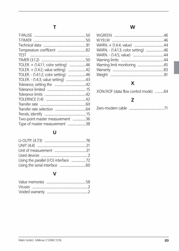
89Mahr GmbH, Millimar C1208/C1216
T
T-PAUSE ...............................................................................50T-TIMER ................................................................................50Technical data ................................................................. 81Temperature coefficient ...........................................82TEST ...........................................................................................TIMER (3.1.2) ....................................................................50TOLER. + (1.4.1.1; color setting) .........................46TOLER. + (1.4.2; value setting) ...........................42TOLER. - (1.4.1.2; color setting) ...........................46TOLER. - (1.4.3; value setting) ..............................43Tolerance, setting the ................................................42Tolerance limited ........................................................... 15Tolerance limits ...............................................................42TOLERNCE (1.4) .............................................................42Transfer rate ......................................................................60Transfer rate selection ...............................................64Trends, identify ............................................................... 15Two-point master measurement ....................36Type of master measurement ...........................38
U
U-OUTP. (4.7.3) ...............................................................76UNIT (4.4) .......................................................................... 21Unit of measurement ................................................ 21Used devices .......................................................................2Using the parallel (I/O) interface ......................72Using the serial interface ........................................60
V
Value memories ............................................................58Viruses .....................................................................................2Voided warranty ..............................................................2
W
W.GREEN ............................................................................46W.YELW ...............................................................................46WARN. + (1.4.4; value) .............................................44WARN. - (1.4.1.3; color setting) ...........................46WARN. - (1.4.5; value) ...............................................44Warning limits .................................................................44Warning limit monitoring ........................................45Warranty ..............................................................................83Weight .................................................................................. 81
X
XON/XOF (data flow control mode) .............64
Z
Zero-modem cable ..................................................... 71
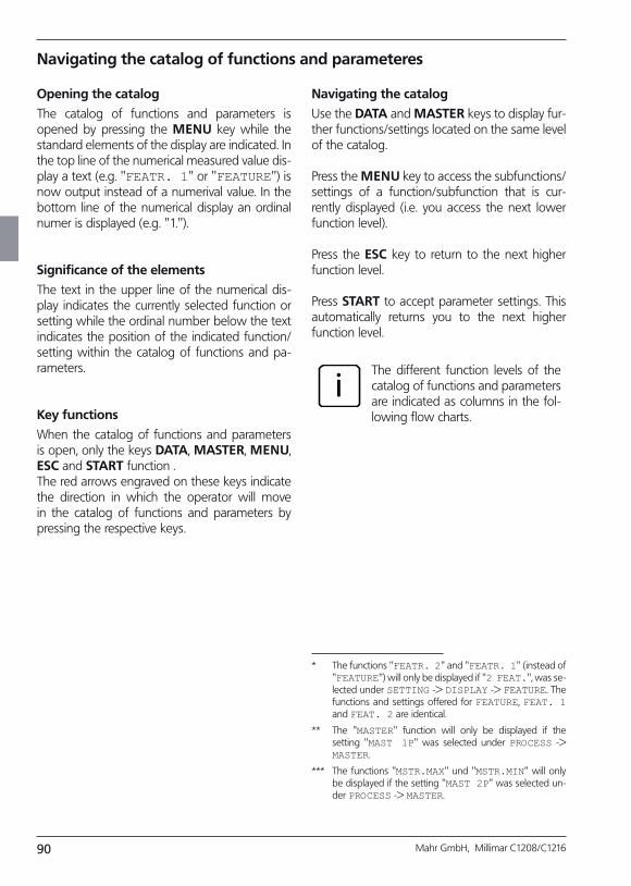
90 Mahr GmbH, Millimar C1208/C1216
Navigating the catalog of functions and parameteres
Opening the catalog
The catalog of functions and parameters is opened by pressing the MENU key while the standard elements of the display are indicated. In the top line of the numerical measured value dis-play a text (e.g. "FEATR. 1" or "FEATURE") is now output instead of a numerival value. In the bottom line of the numerical display an ordinal numer is displayed (e.g. "1.").
Significance of the elements
The text in the upper line of the numerical dis-play indicates the currently selected function or setting while the ordinal number below the text indicates the position of the indicated function/setting within the catalog of functions and pa-rameters.
Key functions
When the catalog of functions and parameters is open, only the keys DATA, MASTER, MENU, ESC and START function .The red arrows engraved on these keys indicate the direction in which the operator will move in the catalog of functions and parameters by pressing the respective keys.
Navigating the catalog
Use the DATA and MASTER keys to display fur-ther functions/settings located on the same level of the catalog.
Press the MENU key to access the subfunctions/settings of a function/subfunction that is cur-rently displayed (i.e. you access the next lower function level).
Press the ESC key to return to the next higher function level.
Press START to accept parameter settings. This automatically returns you to the next higher function level.
iThe different function levels of the catalog of functions and parameters are indicated as columns in the fol-lowing flow charts.
* The functions "FEATR. 2" and "FEATR. 1" (instead of "FEATURE") will only be displayed if "2 FEAT.", was se-lected under SETTING -> DISPLAY -> FEATURE. The functions and settings offered for FEATURE, FEAT. 1 and FEAT. 2 are identical.
** The "MASTER" function will only be displayed if the setting "MAST 1P" was selected under PROCESS -> MASTER.
*** The functions "MSTR.MAX" und "MSTR.MIN" will only be displayed if the setting "MAST 2P" was selected un-der PROCESS -> MASTER.
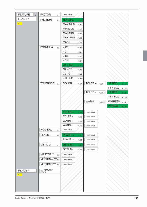
91Mahr GmbH, Millimar C1208/C1216
FEATURE FACTOR num. value
FNCTION NORMAL
MAXIMUM
MINIMUM
MAX-MIN
MAX+MIN
MEAN
FORMULA + C1
- C1
+ C2
- C2
C1 + C2
C1 - C2
C2 - C1
-C1 - C2
TOLERNCE COLOR
TOLER.+
TOLER.-
WARN.+
WARN.-
NOMINAL
num. value
PLAUS.
num. value
num. value
DET LIM DETLIM+
DETLIM-
num. value
num. value
MASTER **
PLAUS. +
PLAUS. -
num. value
num. value
FEAT. 2 * see FEATURE /FEAT.1
TOLER.+
TOLER.-
WARN.
num. value
>T RED
>T YELW
<T RED
<T YELW
W.GREEN
W.YELW
num. value
num. value
num. value
MSTRMAX ***
MSTRMIN *** num. value
FEAT. 1 *
/
1.
2.
1.1
1.2
1.3
1.4
1.5
1.6
1.7
1.8
1.8
1.9
1.2.1
1.2.2
1.2.3
1.2.4
1.2.5
1.2.6
1.3.1
1.3.2
1.3.3
1.3.4
1.3.5
1.3.6
1.3.7
1.3.8
1.4.1
1.4.2
1.4.3
1.4.4
1.4.5
1.6.1
1.6.2
1.6.3
1.6.4
1.4.1.1
1.4.1.2
1.4.1.3
1.4.1.1.1
1.4.1.1.2
1.4.1.2.1
1.4.1.2.2
1.4.1.3.1
1.4.1.3.2
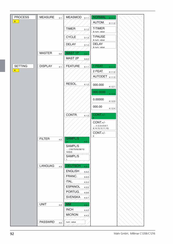
92 Mahr GmbH, Millimar C1208/C1216
PROCESS MEASURE MEASMOD NORMAL
AUTOM.
TIMER T-TIMER& num. value
CYCLE T-PAUSE& num. value
MASTER MAST 1P
MAST 2P
DELAY DELAY& num. value
SETTING DISPLAY FEATURE 1 FEAT.
2 FEAT.
AUTODET
RESOL. 000.000
000.0000
0.00000
000.00
CONTR. CONT.+/-9
CONT.+/-.... (1,2,3,4,5,6,7,8,14,13,12,11,10)
CONT.+/-0
FILTER SAMPL/S21
SAMPL/S.... (150/75/50/38/15/10/5/2)
SAMPL/S1
LANGUAG DEUTSCH
ENGLISH
FRANC.
ITAL.
ESPANOL
PORTUG.
SVENSKA
UNIT MM
INCH
MICRON
PASSWRD num. value
3.
4.
3.1
3.2
4.1
4.2
4.3
4.4
4.5
3.1.1
3.1.2
3.1.3
3.1.4
3.2.1
3.2.2
4.1.1
4.1.2
4.1.3
4.2.1
4.3.1
4.3.2
4.3.3
4.3.4
4.3.5
4.3.6
4.3.7
4.4.1
4.4.2
4.4.3
3.1.1.1
3.1.1.2
4.1.1.1
4.1.1.2
4.1.1.3
4.1.2.1
4.1.2.2
4.1.2.3
4.1.2.4
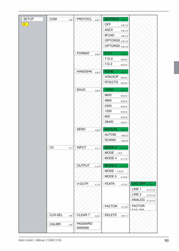
93Mahr GmbH, Millimar C1208/C1216
COM PROTOCL
FORMAT
HANDSHK
BAUD
SEND
MARTALK
OFF
ASCII
M1240
OPTORSS
OPTORSD
SETUP
8-N-1
7-O-2
7-E-2
NONE
XON/XOF
RTS/CTS
19200
9600
4800
2400
1200
600
38400
MANUAL
AUTOM.
SCANN.
I/O INPUT
OUTPUT
V-OUTP.
MODE 0
MODE ...1,2,3
MODE 4
MODE 0
MODE ...1,2,3,4
MODE 5
FEATR. DAC OFF
LINE 1
LINE 2
ANALOG
FACTOR FACTOR& num. value
CLR-SEL
CALIBR PASSWRD0000000
CLEAR ? DELETE
4.
4.6
4.7
4.8
4.9
4.6.1
4.6.2
4.6.3
4.6.4
4.6.5
4.7.1
4.7.2
4.7.3
4.8.1
4.6.1.1
4.6.1.2
4.6.1.3
4.6.1.4
4.6.1.5
4.6.1.6
4.6.2.1
4.6.2.2
4.6.2.3
4.6.3.1
4.6.3.2
4.6.3.3
4.6.4.1
4.6.4.2
4.6.4.3
4.6.4.4
4.6.4.5
4.6.4.6
4.6.4.7
4.6.5.1
4.6.5.2
4.6.5.3
4.7.1.1
4.7.1.5
4.7.2.1
4.7.2.6
4.7.3.1
4.7.3.2
4.8.1.1
4.7.3.1.1
4.7.3.1.2
4.7.3.1.3
4.7.3.1.4
94 Mahr GmbH, Millimar C1208/C1216


www.mahr.com


