118
DP-8800Plus/DP-9900Plus/DP-9900 Digital Ultrasonic Diagnostic Imaging System Service Manual

DP-8800Plus/DP-9900Plus/DP-9900 Digital Ultrasonic Diagnostic Imaging System
Service Manual

I-1
© 2007-2009 Shenzhen Mindray Bio-medical Electronics Co., Ltd. All rights Reserved.
Intellectual Property Statement SHENZHEN MINDRAY BIO-MEDICAL ELECTRONICS CO., LTD. (hereinafter called
Mindray) owns the intellectual property rights to this Mindray product and this manual. This
manual may refer to information protected by copyrights or patents and does not convey any
license under the patent rights of Mindray, nor the rights of others. Mindray does not assume
any liability arising out of any infringements of patents or other rights of third parties.
Mindray intends to maintain the contents of this manual as confidential information.
Disclosure of the information in this manual in any manner whatsoever without the written
permission of Mindray is strictly forbidden.
Release, amendment, reproduction, distribution, rent, adaptation and translation of this
manual in any manner whatsoever without the written permission of Mindray is strictly
forbidden.
, , , , are the registered trademarks or
trademarks owned by Mindray in China and other countries. All other trademarks that
appear in this manual are used only for editorial purposes without the intention of improperly
using them. They are the property of their respective owners.
Responsibility on the Manufacturer Party Contents of this manual are subject to changes without prior notice.
All information contained in this manual is believed to be correct. Mindray shall not be liable for errors contained herein nor for incidental or consequential damages in connection with the furnishing, performance, or use of this manual.
Mindray is responsible for safety, reliability and performance of this product only in the condition that:

I-2
• all installation operations, expansions, changes, modifications and repairs of this product are conducted by Mindray authorized personnel;
• the electrical installation of the relevant room complies with the applicable national and local requirements;
• the product is used in accordance with the instructions for use.
WARNING: It is important for the hospital or organization that employs this
equipment to carry out a reasonable service/maintenance plan. Neglect of this may result in machine breakdown or injury of human health.
Warranty THIS WARRANTY IS EXCLUSIVE AND IS IN LIEU OF ALL OTHER WARRANTIES, EXPRESSED OR IMPLIED, INCLUDING WARRANTIES OF MERCHANTABILITY OR FITNESS FOR ANY PARTICULAR PURPOSE.
Exemptions
Mindray's obligation or liability under this warranty does not include any transportation or other charges or liability for direct, indirect or consequential damages or delay resulting from the improper use or application of the product or the use of parts or accessories not approved by Mindray or repairs by people other than Mindray authorized personnel.
This warranty shall not extend to:
any Mindray product which has been subjected to misuse, negligence or accident;
any Mindray product from which Mindray's original serial number tag or product identification markings have been altered or removed;
any product of any other manufacturer.
Return Policy Return Procedure In the event that it becomes necessary to return this product or part of this product to Mindray, the following procedure should be followed: 1. Obtain return authorization: Contact the Mindray Service Department and obtain a
Customer Service Authorization (Mindray) number. The Mindray number must appear

I-3
on the outside of the shipping container. Returned shipments will not be accepted if the Mindray number is not clearly visible. Please provide the model number, serial number, and a brief description of the reason for return.
2. Freight policy: The customer is responsible for freight charges when this product is shipped to Mindray for service (this includes customs charges).
3. Return address: Please send the part(s) or equipment to the address offered by Customer Service department
Company Contact Manufacturer: Shenzhen Mindray Bio-Medical Electronics Co., Ltd.
Address: Mindray Building, Keji 12th Road South, Hi-tech Industrial Park, Nanshan, ShenzhenShenZhen518057, P.R.China,518057
Tel: +86 755 26582479 26582888
Fax: +86 755 26582934 26582500
EC-Representative: Shanghai International Holding Corp. GmbH(Europe)
Address: Eiffestraβe 80, 20537 Hamburg Germany
Tel: 0049-40-2513175
Fax: 0049-40-255726
S-1
Safety Precautions
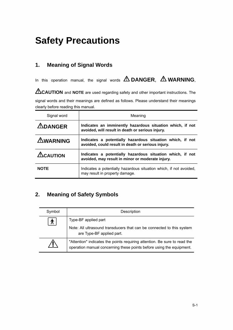
1. Meaning of Signal Words
In this operation manual, the signal words DANGER, WARNING,
CAUTION and NOTE are used regarding safety and other important instructions. The
signal words and their meanings are defined as follows. Please understand their meanings clearly before reading this manual.
Signal word Meaning
DANGER Indicates an imminently hazardous situation which, if not avoided, will result in death or serious injury.
WARNING Indicates a potentially hazardous situation which, if not avoided, could result in death or serious injury.
CAUTION Indicates a potentially hazardous situation which, if not avoided, may result in minor or moderate injury.
NOTE Indicates a potentially hazardous situation which, if not avoided, may result in property damage.
2. Meaning of Safety Symbols
Symbol Description
Type-BF applied part
Note: All ultrasound transducers that can be connected to this system are Type-BF applied part.
"Attention" indicates the points requiring attention. Be sure to read the operation manual concerning these points before using the equipment.

S-2
3. Safety Precautions
Please observe the following precautions to ensure patient and operator safety when using this system.
DANGER: Do not use flammable gasses such as anesthetic gas, oxygen or
hydrogen, or flammable liquids such as ethanol, near the system, because there is danger of explosion.
WARNING:
1. Do connect the plugs of the system and peripherals connected to the system to the wall receptacle meeting the ratings indicated on the rating nameplate. Using adapter or multi-functional receptacle may affect the system’s grounding performance and thus cause leakage current exceeding safety requirement. Be sure to connect the video printer to the designated AC outlet on the system with the provided cable. Using other cables may cause electric shock.
2. Be sure to connect the potential-equalization lead wire before inserting the system power plug into the receptacle and be sure to remove the system power plug from the receptacle before disconnecting the wire, in order to avoid electric shock.
3. Connect the earth conductor only before turning ON the system. Disconnect the grounding cable only after turning OFF the system. Otherwise, electric shock may result.
4. For the connection of power and grounding, follow the appropriate procedures described in the operation manual. Otherwise, there is risk of electric shock. Do not connect the grounding cable to a gas pipe or water pipe, otherwise functional grounding may not be effective or there may be risk of a gas explosion.
5. Before cleaning the system, be sure to disconnect the power cable to avoid electric shock.

S-3
6. No waterproof device is applied to the system. Do not use the system in any place with the possibility of water ingress. There is risk of electric shock if any water is sprayed on or into the system. If you carelessly spray any water onto/into the system, contact the Mindray sales office, customer service department or representative.
7. Use the transducer carefully. In case that the human body contacts the scratched transducer surface, immediately stop using the transducer and contact the Mindray sales office, customer service department or representative. There is risk of electric shock if using the scratched transducer.
8.Be careful not to let the patient contact the ultrasound equipment. If the ultrasound equipment is defective, there is risk of electric shock.
9. Do not use the transducers other than those provided by Mindray. If a transducer other than those provided by Mindray is connected, the equipment and the transducer may be damaged, causing an accident such as a fire in the worst case.
10. Do not subject the transducers to knocks. Use of defective transducers may cause electric shock.
11. Do not open the shell or panel. If open the shell when the equipment is powered on, there may be a short circuit or electric shock.
12. Do not use the equipment at the same time use equipment such as an electric scalpel, high-frequency therapy equipment or a defibrillator, etc.
13. Precautions during transportation: When moving the equipment, hold the handle. If the user holds other sections, the equipment may be subject to unnatural force and may be damaged. Do not move the equipment in the left/right direction. If the equipment is moved in the left/right direction, the equipment may fall.
14. Accessory equipments connected to the analogue and digital interfaces must comply with relevant IEC standards. Furthermore all configurations should comply with the standard IEC60601-1-1. Everybody who connects additional equipments to the signal input part or signal output part configures a medical system, and is therefore responsible that the system complies with the requirements of IEC60601-1-1. If in doubt, consult Mindray customer service department or your local distributor.

S-4
15. Prolonged and repeated use of keyboards can result in hand or arm nerve disorders in some individuals. Observe the local institution work safety/health regulations on keyboard use.
CAUTION:
1.Precautions concerning clinical examination techniques
(1) This system can only be used by medical personnel fully trained in clinical examination techniques.
(2) This manual does not describe clinical examination techniques. Selection of the proper clinical examination technique must be based on specialized training and clinical experience.
2.Malfunctions due to radiowaves
(1) Use of radiowave-emitting devices in the proximity of this kind of medical electronic system may interfere with its operation. Do not bring or use devices which generate radio waves, such as cellular telephones, transceivers, and radio controlled toys, in the room where the system is installed.
(2) If a user brings a device which generates radio waves near the system, he must be instructed to immediately turn OFF the device. This is necessary to ensure the proper operation of the system.
3. Precautions concerning installation and movement of the system
(1) Be sure to install the system on a level floor and lock the casters. Otherwise, the system may move, and injure the patient.
(2) Do not push the system from the sides. If the system is pushed from the sides, it may fall down and cause injury.
(3) When the system is moved over a sloped surface, it must be moved slowly by two persons. Otherwise, the system may slide unexpectedly and cause a serious injury.
(4) Do not sit on the system. The system may move, causing you to lose your balance and fall.
(5) Do not place any objects on top of the monitor. They may fall, causing injury.

S-5
(6) Confirm that the peripheral units are secured before you move the system. Otherwise, the peripheral units may fall and cause injury.
(7) When the system is moved over a step, exercise caution to protect the system from falling. When holding the system at the bottom to help move it over a step, take special care to prevent hand injuries.
4.Do not vibrate the equipment excessively (when moving the equipment); otherwise the mechanical parts (such as casters) may be damaged. If the system is often moved on a bumpy floor, contact the Mindray sales office, customer service department or representative.
5. Do not connect this system to outlets with the same circuit breakers and fuses that control the current of devices such as life-support systems. If this system malfunctions and generates an overcurrent, or when there is an instantaneous current at power ON, the circuit breakers and fuses of the building’s supply circuit may be tripped.
6. Always keep the machine dry. Avoid transporting this machine quickly from the cold place to the warm place, otherwise condensation or water drops may be formed, which will cause short circuit.
7. If the circuit breaker is tripped or the fuse is blown, it indicates that the machine or the peripheral devices have problems. In these cases, the user cannot repair by him but contact the Mindray sales office, customer service department or representative.
8. There is no risk of high-temperature burns during routine ultrasound examinations, even if, due to environment temperature and exam modes, the surface temperature of the transducer exceeds the body temperature of the patient. To prevent high-temperature burns, do not apply the transducer to the same region on the patient for a long time. Apply the transducer only for as long as required time for diagnosis.
9.After the sterilization or disinfection of accessories, chemicals must be washed out or gases must be discharged thoroughly from the accessories. Remaining residual chemicals or gases will not only result in damage to the accessories but also can be harmful to human bodies.

S-6
10.Before examining a new patient, press 『Patient』 to delete the patient information and data recorded in the memory for the previous patient. Otherwise, the new data may be confused with the data of the previous patient.
11. Do not pull out plugs of the system and its accessories without turning OFF the power. Otherwise it may result in equipment damage or even electric shock.
12. Do not turn OFF the power supply of the system during printing, saving, or invoking. Otherwise it may result in abnormality of these processes.
NOTE: 1. Do not use the system in the vicinity of strong electromagnetic field (such as the transformer), which may affect the performance of the monitor.
2. Do not use the system in the vicinity of high-frequency radiation source (such as the cellular phone), which may affect the performance of the machine or even lead to failure.
3. To avoid damaging the system, do not use the system in following environment:
(1) Locations exposed to direct sunlight
(2) Locations subject to sudden changes in temperature
(3) Dusty locations
(4) Locations subject to vibration
(5) Locations near heat generators
(6) Locations with high humidity
4. Turn ON the system only after the power has been OFF for more than 10 seconds. If the system is turned ON immediately after being turned OFF, it may result in malfunction of the system.
5. Turn OFF the auxiliary power switch or stop transmission through the [Freeze] key before connecting or disconnecting a transducer. If a transducer is connected or disconnected with an image displayed, the system and/or the transducer may malfunction.
6. After using the transducer, remove the ultrasound gel on it and place the transducer on the transducer holder. Otherwise, water in the gel may enter the acoustic lens, thus adversely affecting the performance and safety of the transducer.
S-7
7. You can record the registration data (including the hospital data and patient data). To ensure the security of the data, be sure to back up the data on external storage media. Data stored in the system may be lost due to improper operation or an accident.
8. Do not apply external force to the control panel (e.g. leaning against it). Otherwise it may damage the system.
9. If the system is used in a small room, the room temperature may rise. Therefore, proper ventilation shall be provided.
10. The fuse, which is inside the machine, can be replaced only by the Mindray service engineer or the technician specified by Mindray.
11. When disposing of this system or any part of the system, contact Mindray sales office, customer service department or representative. Do not dispose of this system without consulting Mindray sales office, customer service department or representative first. Mindray does not assume any responsibility for damage resulting from disposal of this system without consulting Mindray.
12. Deterioration of electrical and mechanical safety characteristics (such as generation of a leakage current or deformation/abrasion of mechanical parts) and of image sensitivity and resolution may occur over a period of time. To ensure system performance, signing a maintenance and service contract to avoid accidents and misdiagnose is recommended.
13. The output power outlets on the main unit are used for providing power to recommended external optional devices. Do not connect other devices to the outlets, otherwise the output power may be exceeded and the system may malfunction.
4. Warning Labels
Various WARNING labels are attached to this system in order to call the user's attention to
potential hazards.
The symbol on the WARNING labels attached to the system indicates safety
precautions.
The name, appearance, and the indication of each WARNING label are described in the
Operation Manual. Read them carefully and understand them.

C-1
Contents
Chapter 1 System Introduction .............................................................. 1-1
1.1. Introduction of DP-8800Plus ........................................................................... 1-1
1.1.1. Appearance ............................................................................................ 1-1
1.1.2. Rear Panel ............................................................................................. 1-3
1.1.3. Control Panel ......................................................................................... 1-4
1.2. Introduction of DP-9900Plus/DP-9900 ............................................................ 1-6
1.2.1. Appearance ............................................................................................ 1-6
1.2.2. Rear Panel ............................................................................................. 1-8
1.2.3. Control Panel ....................................................................................... 1-10
Chapter 2 Hardware Introduction ........................................................... 2-1
2.1. Hardware System ........................................................................................... 2-1
2.2. Boards ............................................................................................................ 2-1
2.2.1. Main Board ............................................................................................. 2-1
2.2.2. Transducer Board ................................................................................... 2-2
2.2.3. Connection Board ................................................................................... 2-3
2.2.4. Output Board .......................................................................................... 2-9
2.2.5. I/O Board .............................................................................................. 2-12
2.3. Power Supply Board ..................................................................................... 2-12
2.3.1. Introduction .......................................................................................... 2-12
2.3.2. Working Procedure ............................................................................... 2-13
2.3.3. Circuit Description ................................................................................ 2-13
2.3.4. Protection Circuit .................................................................................. 2-14
2.3.5. Maintenance ......................................................................................... 2-15
2.4. Principle of the LCD ...................................................................................... 2-18
2.4.1. Operating Principle of the Inverter Module ........................................... 2-18
2.4.2. Working principle of the regulating board ............................................. 2-20
Chapter 3 Disassembly of DP-9900Plus/DP-9900 ................................. 3-1
3.1. System Structure ............................................................................................ 3-1
3.2. Disassembly of Monitor................................................................................... 3-2
3.3. Disassembly of Screen ................................................................................... 3-3
3.4. Disassembly of Keyboard ............................................................................... 3-3

Contents
C-2
3.4.1. Disassembly of Keyboard Cover ............................................................ 3-3
3.4.2. Disassembly of Trackball ........................................................................ 3-4
3.4.3. Disassembly of Keyboard Board ............................................................ 3-5
3.4.4. Disassembly of TGC Board .................................................................... 3-5
3.5. Disassembly of CD-ROM ................................................................................ 3-6
3.5.1. Locking Casters ...................................................................................... 3-6
3.5.2. Disassembly of Drawer and Transducer Cable Hanger .......................... 3-6
3.5.3. Disassembly of Rear Cover of Neck ....................................................... 3-7
3.5.4. Disassembly of Top Cover ...................................................................... 3-7
3.5.5. Disassembly of Left Cover ..................................................................... 3-8
3.5.6. Disassembly of Right Cover ................................................................... 3-9
3.5.7. Disassembly of Front Cover ................................................................... 3-9
3.5.8. Disassembly of CD-ROM ..................................................................... 3-10
3.6. Disassembly of I/O Board ............................................................................. 3-11
3.7. Disassembly of Air Outlet Fan Assembly ...................................................... 3-12
3.8. Disassembly of Hard Disk ............................................................................. 3-12
3.9. Disassembly of Power Conversion Board ..................................................... 3-13
3.10. Disassembly of Air Intake Fan Assembly ...................................................... 3-14
3.11. Disassembly of Output Board, Main Board and Power Supply Board .......... 3-15
3.12. Disassembly of Transducer Board ................................................................ 3-16
3.13. Disassembly of Cabinet ................................................................................ 3-16
3.14. Diagram ........................................................................................................ 3-17
3.15. Disassembly of the LCD Monitor Assembly .................................................. 3-18
3.16. Replacing the OSD Board of the LCD Monitor .............................................. 3-19
3.17. Replacing the inverter board and control board of the LCD .......................... 3-20
3.18. Replacing the LCD screen of the LCD Monitor ............................................. 3-21
3.19. Disassembly of the LCD support arm assembly ........................................... 3-23
Chapter 4 Disassembly of DP-8800Plus ................................................ 4-1
4.1. System Structure ............................................................................................ 4-1
4.2. Disassembly of Monitor................................................................................... 4-2
4.3. Disassembly of Screen ................................................................................... 4-3
4.4. Disassembly of Printer .................................................................................... 4-4
4.5. Disassembly of Keyboard ............................................................................... 4-4
4.6. Disassembly of Trackball ................................................................................ 4-5
4.7. Disassembly of TGC Board ............................................................................ 4-5

Contents
C-3
4.8. Disassembly of Transducer Cable Hanger ...................................................... 4-6
4.9. Disassembly of Handle ................................................................................... 4-7
Chapter 5 Maintenance Requirements .................................................. 5-1
5.1. Tools and Consumables .................................................................................. 5-1
5.2. Maintenance Personnel .................................................................................. 5-2
Chapter 6 System Maintenance ............................................................. 6-1
6.1. Cleaning .......................................................................................................... 6-1
6.1.1. Procedure ............................................................................................... 6-1
6.1.2. Details .................................................................................................... 6-1
6.2. Software Maintenance .................................................................................... 6-2
6.2.1. Software Upgrade .................................................................................. 6-4
6.2.2. Installation/Uninstallation of DICOM ....................................................... 6-5
6.2.3. System Self-check .................................................................................. 6-6
6.2.4. LCD test ................................................................................................. 6-6
Chapter 7 Troubleshooting ..................................................................... 7-1
7.1. Power Supply .................................................................................................. 7-1
7.2. Monitor ............................................................................................................ 7-1
7.3. Troubleshooting of LCD Blank Screen ............................................................ 7-2
7.4. Troubleshooting of Other Malfunctions of the LCD ......................................... 7-2
7.5. Startup ............................................................................................................ 7-3
7.6. Use ................................................................................................................. 7-4
7.7. Software .......................................................................................................... 7-5
7.8. Others ............................................................................................................. 7-5
Appendix A Electrical Safety Inspection .................................................. A-1

1-1
Chapter 1 System Introduction
1.1. Introduction of DP-8800Plus
1.1.1. Appearance
<1><2>
<3>
<4><5><6><7>
<8>
<9>
<10>
<5>
<6>
<7>
Front View

System Introduction
1-2
<11>
<13>
<12>
<14>
Left View
No. Part Introduction
<1> Monitor Display images and parameters, etc.
<2> Transducer cable hanger
Hook for the transducer cable
<3> Transducer holder Place the transducer provisionally
<4> Printer area Place the video printer
<5> Video out Connect the video printer
<6> AC out Connect the AC power cable for the video printer
<7> Remote Connect the remote cable for the video printer
<8> Transducer socket Connect or disconnect the transducer with the main unit
<9> Footswitch switch socket
Connect or disconnect footswitch
<10> Casters Lock or move the system
<11> Control panel User interface
<12> Handle Move the system
<13> CD-RW Backup data to a CD or read data from a CD
<14> Power switch Power on / off

System Introduction
1-3
1.1.2. Rear Panel
Rear View
<15>
<16>
<17>
<18>
<19><20>
<20>
<21>
I/O Panel
No. Name Introduction
<15> Video out Connect the video printer or other video device

System Introduction
1-4
No. Name Introduction
<16> Graph/text printer port
Connects the graph/text printer
<17> S-Video port Video output
<18> RS-232 Rreserved
<19> VGA port VGA output
<20> USB port Connects the USB storage device or graph/text printer, etc.
<21> Ethernet port Connects network
<22> AC input Connects the power cable for the system
<23> Equipotential terminal
Equipotential connecting
1.1.3. Control Panel
IP
A B C++
< >1 < >2 < >3 < >4 < >5 < >6
< >7
< >8
< >9
< >10
< >11
< >12
< >13
< >14
< >15
< >16
< >17
< >18< >19
< >20
< >21
< >22
< >23
< >24
< >25
< >26
< >27
< >28 <29>
< >30 < >31
< >32
< >34< >33
Control Panel

System Introduction
1-5
NO. Key Function
<1> Patient Delete the data for the previous patient, including the ID and
measured values, and begin with a new patient.
<2> Info The patient information screen appears.
<3> Preset Invoke the registered initial settings (presets).
<4> File Activate storage or load files system
<5> Probe Switch transducers
<6> ABD/GYN/OB/SML Select exam mode
<7> Character Key Used to enter characters and symbols
When backlight of SHIFT key is on, the symbol in the upper
row on keys can be entered.
When pressing CAPS key, the capital letter can be entered.
<8> TGC Adjust the ultrasound echo reception sensitivity according to
the depth from the body surface.
<9> Puncture Enter needle guide menu
<10> F.Posi Enter the focus position adjusting mode.
<11> F.Num Enter the focus number adjusting mode.
<12> A.power Enter the acoustic power adjusting mode.
<13> IP Adjust the image quality according to the registered image
conditions.
<14> Parameter adjust
knob
Adjust some value of Puncture, F.Posi, F.Num, A.Power and IP
with combination of corresponding key.
<15> Clear Clear comments, body marks, measurements and results on
screen
<16> Exit Exit the current work mode
<17> Arrow Enter the arrow comment mode
<18> Set Determine the cursor position for measurement, and confirm
the selected items, and adjust the value or items in menus etc.
<19> Change Change the fixed end or active end in measurement.
<20> Back Delete the comment or the previous operations, and adjust the
value or items in menus etc.
<21> Trackball Move the cursor or mark during image movement or
measurement.
<22> Menu Open or close the menu on screen.
<23> Measure Go into measurement mode
<24> BodyMark Enter body marks mode.
<25> Comment Go into comment mode
<26> M-Mark Enter M-Mark mode

System Introduction
1-6
NO. Key Function
<27> Depth/Zoom/
Rotation
Adjust the viewing depth for display, the zoom mode, and the
arrow rotation of the ultrasound images.
<28> Cine Switch Manual/Auto CINE review. When the 『Cine』 lamp
lights on, the system enter Manual Review mode; when the
『Cine』 lamp is off the system exits Manual Review mode.
<29> Zoom Enter the mode of amplifying the image
<30> B/M/M+B/B+B Select image mode
<31> HRev / VRev Reversal the image horizontally or vertically
<32> Gain Adjust the sensitivity of black/white images.
<33> Print Activate a printing function for a video printer connected.
<34> Freeze Freeze and unfreezes the image. If image is frozen, Output of
acoustic power is stopped.
1.2. Introduction of DP-9900Plus/DP-9900
1.2.1. Appearance
Front View

System Introduction
1-7
<9>
<8>
<7>
<6>
Left View
No. Part Introduction
<1> Monitor Display images and parameters, etc. 14″ monitor
<2> Transducer cable hanger
Hook for the transducer cable
<3> Transducer holder Place the transducer provisionally
<4> Transducer socket Connect or disconnect the transducer with the main unit
<5> Footswitch socket Connect or disconnect footswitch
<6> Control panel User interface
<7> Handle Move the system
<8> CD-RW Backup the data in hard disk or USB storage device into a CD, or read out the files from a CD.
<9> Power switch Power on / off

System Introduction
1-8
1.2.2. Rear Panel
Rear View
I/O Panel
System Introduction
1-9
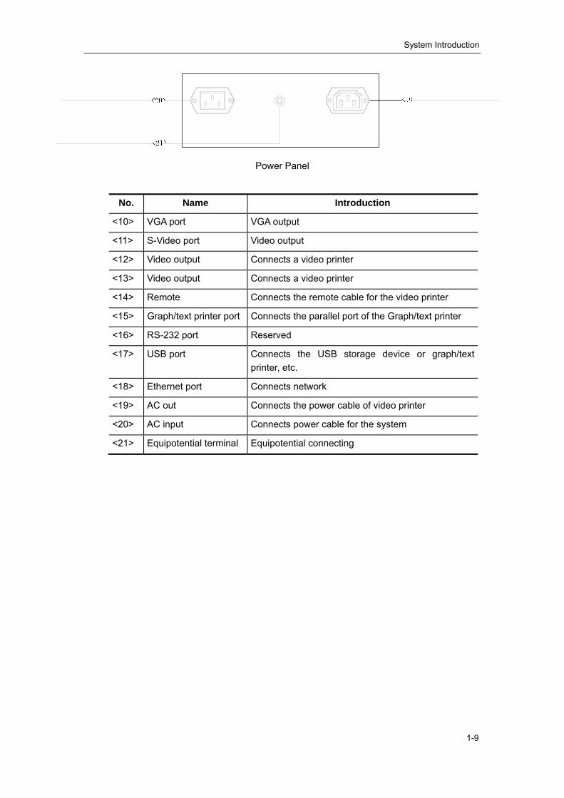
Power Panel
No. Name Introduction
<10> VGA port VGA output
<11> S-Video port Video output
<12> Video output Connects a video printer
<13> Video output Connects a video printer
<14> Remote Connects the remote cable for the video printer
<15> Graph/text printer port Connects the parallel port of the Graph/text printer
<16> RS-232 port Reserved
<17> USB port Connects the USB storage device or graph/text printer, etc.
<18> Ethernet port Connects network
<19> AC out Connects the power cable of video printer
<20> AC input Connects power cable for the system
<21> Equipotential terminal Equipotential connecting
System Introduction
1-10
1.2.3. Control Panel
TGC
Gain
Depth
Zoom
Rotation
( )( )
( )( )
( )( )
( )( )
( )( )
( )( )
( )( )
( )( )
IP
A B C++
<1> <2> <3> <4>
<8>
< >7
< >9
< >10
< >11
< >12
< >13
< >14
< >15
< >16
< >17< >18
< >19< >21
< >23
< >24< >25
< >26
< >28
< >29 <30>
< >31
< >32
< >33
< >34< >35
Control Panel
NO. Key Function
<1> Patient Delete the data for the previous patient, including the ID and measured values, and begin with a new patient.
<2> Info The patient information screen appears.
<3> Preset Invoke the registered initial settings (presets).
<4> File Activate the stored or loaded file system
<5> ABD/GYN/OB/CAR/SML
Select the exam mode
<6> Character Key Used to enter characters and symbols When the backlight indicator of SHIFT key is on, the symbols on the upper row of the keys can be entered.
<7> TGC Adjust the ultrasound echo reception sensitivity according to the depth.
<8> Puncture Enter/exit the biopsy status
<9> F.Posi Adjust the focus position.
<10> F.Num Adjust the focus number.
<11> A.power Adjust the acoustic power

System Introduction
1-11
NO. Key Function
<12> IP Select the combination of image processing parameters, to adjust the image display effect.
<13> Parameter adjust knob Adjust some value of Puncture, F.Posi, F.Num, A.Power and IP with combination of corresponding key.
<14> Clear Clear all comments, bodymarks, measurement scales and general measurement results on the screen
<15> Exit Exit the current work mode
<16> Arrow Enter the arrow comment mode
<17> Set Determine the cursor position for measurement, and confirm the selected items, and adjust the value or items in menus etc.
<18> Change Switch between the fixed end and active end in the measurement.
<19> Back Delete the arrow comment or return to the previous operation, and adjust the value or items in menus etc.
<20> Trackball Move the cursor or mark during image movement or measurement.
<21> Menu Open or close the menu on the screen.
<22> Measure Enter/exit the measurement mode
<23> Comment Enter/exit the comment mode
<24> M-Mark Enter/exit the M-Mark mode
<25> BodyMark Enter/exit the BodyMark mode.
<26> Depth/Zoom/Rotation Adjust the viewing depth for display, the zoom mode, and the arrow rotation of the ultrasound images.
<27> Probe Switch transducers
<28> Freq/THI Adjust the transducer frequency and switch to the harmonic frequency of 35C50HA.
<29> Cine Enter the manual playback mode.
<30> Zoom Enter the mode of amplifying the image
<31> HRev / VRev Reverse the image horizontally or vertically
<32> B/M/M+B/B+B Select the image mode
<33> Gain Adjust the sensitivity of black/white images.
<34> Freeze Freeze or unfreeze the image. If an image is frozen, the output of acoustic power is stopped.
<35> Print Activate the printing function for the video printer connected.
2-1
Chapter 2 Hardware Introduction
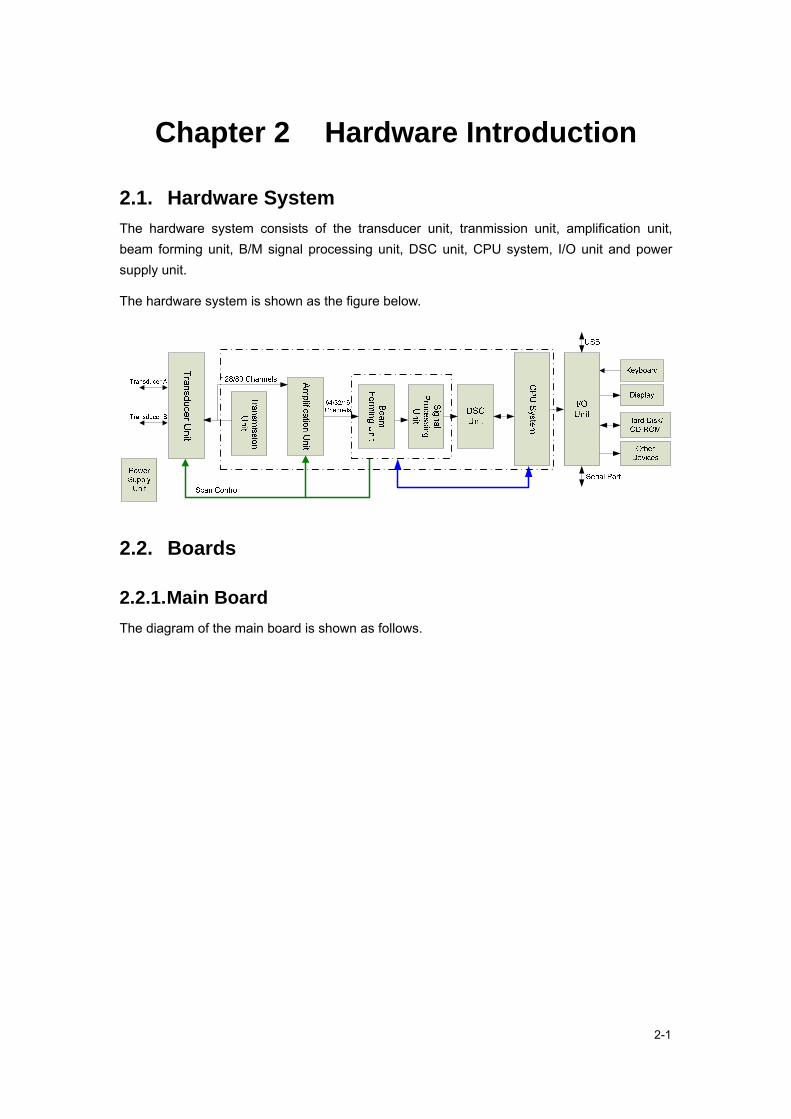
2.1. Hardware System The hardware system consists of the transducer unit, tranmission unit, amplification unit, beam forming unit, B/M signal processing unit, DSC unit, CPU system, I/O unit and power supply unit.
The hardware system is shown as the figure below.
2.2. Boards
2.2.1. Main Board The diagram of the main board is shown as follows.

Hardware Introduction
2-2
The front-end transmission circuit consists of MD1210 and TC2320. The reception circuit includes ADG714, VCA8617 and ADS5277. The transmission sequence control and reception channel selection are completed by FPGA.
The digital circuit consists of the CPU system and the FPGA system. The CPU system includes CPU and the peripheral and interface circuit: FLASH, SDRAM, CPLD, power monitor (ADT7462), reset circuit, clock circuit, real-time clock circuit (MAX6900), IDE interface, USB interface, and Ethernet interface; The FPGA system includes FPGA, beam forming SSRAM, DSC and display SSRAM, DAC conversion circuit and video interface; CPU is connected to the peripheral and interface circuit with bus and also to FPGA with bus; The signal processing is performed in FPGA.
2.2.2. Transducer Board The diagram of the transducer board is shown as follows.

Hardware Introduction
2-3
The transducer board consists of transducer sockets A and B, 128 channel alternative relay, transducer and board ID output circuit, relay control circuit and power filter circuit.
2.2.3. Connection Board The connection board provides connection platform for the main board, transducer board, power supply board, keyboard, fans, peripherals and output interfaces and is convenient for tests of input and output signals on boards. The board, which is grounded well and conforms to the requirements of EMC, can filter differential mode and common mode noise. DP-9900, DP-9900Plus and DP-8800Plus all use the board.
The diagram of the connection board is shown as follows.

Hardware Introduction
2-4
Power Supply Board
Main Board
Main Board
Main Board
Transducer Board
Transducer Board
Lower Fan 20pin
6pin4pin*3 4pin
Hard connection
Soft connection
Display13.5v
Upper Fan12v
Keyboard5v,12v
CD-ROM5v,12v
Diskette Drive5v,12v
Hard Disk5v,12v
12V
Power Supply Filter
2.5V
3.3VD1V5
High-frequency Filter
5V,12V 13.5V 12V
12V
POUT[128:81]
POUT[80:1]FID[8:1]
ENBNAIDRDNBIDRDEX_EN
PHVA-5A+5
D12VD+5
A13V5D3V3
D+5,D12V,A13V5
5V,12V,13.5V
Voltage Reduction
3V1.2V
2.2.3.1. Interfaces to Power Supply Board The interfaces between the connection board and the power supply board are defined in the table below.
P1
A B C 1 PHV PHV PHV
2 NC NC NC
3 GND GND GND
4 A-5 A-5 A-5
5 GND GND GND
6 12V 12V 12V
7 GND GND GND

Hardware Introduction
2-5
8 A+5 A+5 A+5
9 A+5 A+5 A+5
10 A+5 A+5 A+5
11 GND GND GND
12 HVC GND GND
13 GND GND GND
14 GND GND GND
15 2V5 2V5 2V5
16 GND GND GND
17 1V5 1V5 1V5
18 1V5 1V5 1V5
19 GND GND GND
20 GND GND GND
21 3V3 3V3 3V3
22 3V3 3V3 3V3
23 GND GND GND
24 GND GND GND
25 13V5 13V5 13V5
26 NC GND GND
27 NC GND NC
28 GND GND GND
29 NC GND NC
30 GND GND GND
31 D+5 D+5 D+5
32 D+5 D+5 D+5
2.2.3.2. Interfaces to Main Board The interfaces between the connection board and the main board are defined in the table below.
P2
A B C D E 1 HV HV HV HV HV
2 GND GND GND GND GND
3 FA-5 FA-5 FA-5 FA-5 FA-5
4 GND GND GND GND 12V
5 GND GND GND GND GND
6 FA+5 FA+5 FA+5 FA+5 FA+5

Hardware Introduction
2-6
7 FA+5 FA+5 FA+5 FA+5 FA+5
8 GND GND GND GND GND
9 GND GND GND GND HVC
10 FA3V FA3V FA3V FA3V FA3V
11 GND GND GND GND GND
12 GND GND GND GND GND
13 GND GND GND GND GND
14 F1V2 F1V2 F1V2 F1V2 F1V2
15 F1V2 F1V2 F1V2 F1V2 F1V2
16 GND GND GND GND GND
17 FD3V3 FD3V3 FD3V3 FD3V3 FD3V3
18 FD3V3 FD3V3 FD3V3 FD3V3 FD3V3
19 13V5 GND GND GND GND
20 GND GND GND GND GND
21 FD+5 FD+5 FD+5 FD+5 FD+5
22 FD+5 FD+5 FD+5 FD+5 FD+5
P3
1 GND POUT92 POUT90 POUT89 POUT96
2 POUT86 GND POUT91 POUT112 POUT94
3 POUT95 POUT88 GND POUT85 POUT110
4 POUT93 POUT82 POUT81 GND POUT87
5 POUT98 POUT84 POUT109 POUT83 GND
6 GND POUT100 POUT106 POUT108 POUT111
7 POUT99 GND POUT102 POUT107 POUT105
8 POUT97 POUT104 GND POUT101 POUT126
9 POUT121 POUT103 POUT122 GND POUT128
10 POUT125 POUT127 POUT123 POUT124 GND
11 GND POUT119 POUT120 POUT117 POUT118
12 POUT114 GND POUT113 POUT116 POUT115
13 GND GND GND GND GND
14 ENB FID1 FID2 FID3 FID4
15 FID5 FID6 FID7 FID8 GND
16 /AIDRD /BIDRD GND GND GND
17 GND GND GND GND GND
18 GND GND GND GND GND
19 GND GND GND GND GND

Hardware Introduction
2-7
20 GND GND GND GND GND
21 GND GND GND GND GND
22 GND GND GND GND GND
P4
1 GND GND GND GND GND
2 GND GND GND GND GND
3 GND POUT2 POUT15 POUT14 POUT16
4 POUT4 GND POUT13 POUT11 POUT12
5 POUT1 POUT10 GND POUT6 POUT9
6 POUT3 POUT7 POUT8 GND POUT5
7 POUT22 POUT25 POUT28 POUT26 GND
8 GND POUT19 POUT20 POUT24 POUT27
9 POUT31 GND POUT21 POUT32 POUT30
10 POUT29 POUT18 GND POUT23 POUT48
11 POUT34 POUT45 POUT17 GND POUT46
12 POUT36 POUT42 POUT47 POUT41 GND
13 GND POUT33 POUT40 POUT44 POUT43
14 POUT35 GND POUT39 POUT38 POUT37
15 POUT58 POUT60 GND POUT64 POUT62
16 POUT63 POUT54 POUT57 GND POUT80
17 POUT61 POUT56 POUT59 POUT78 GND
18 GND POUT66 POUT53 POUT52 POUT55
19 POUT68 GND POUT51 POUT50 POUT49
20 POUT77 POUT79 GND POUT73 POUT74
21 POUT65 POUT69 POUT75 GND POUT76
22 POUT67 POUT71 POUT72 POUT70 GND
2.2.3.3. Interfaces to Transducer Board The interfaces between the connection board and the transducer board are defined in the table below.
P5
A B C D E 1 GND POUT92 POUT90 POUT89 POUT96
2 POUT86 GND POUT91 POUT112 POUT94
3 POUT95 POUT88 GND POUT85 POUT110
4 POUT93 POUT82 POUT81 GND POUT87
5 POUT98 POUT84 POUT109 POUT83 GND
6 GND POUT100 POUT106 POUT108 POUT111

Hardware Introduction
2-8
7 POUT99 GND POUT102 POUT107 POUT105
8 POUT97 POUT104 GND POUT101 POUT126
9 POUT121 POUT103 POUT122 GND POUT128
10 POUT125 POUT127 POUT123 POUT124 GND
11 GND POUT119 POUT120 POUT117 POUT118
12 POUT114 GND POUT113 POUT116 POUT115
13 GND GND GND GND GND
14 ENB FID1 FID2 FID3 FID4
15 FID5 FID6 FID7 FID8 GND
16 /AIDRD /BIDRD GND GND GND
17 GND GND GND GND GND
18 A+5 A+5 A+5 A+5 A+5
19 GND GND GND GND GND
20 GND GND GND GND GND
21 GND GND GND GND GND
22 GND GND GND GND GND
P6
1 GND GND GND GND GND
2 GND GND GND GND GND
3 GND POUT2 POUT15 POUT14 POUT16
4 POUT4 GND POUT13 POUT11 POUT12
5 POUT1 POUT10 GND POUT6 POUT9
6 POUT3 POUT7 POUT8 GND POUT5
7 POUT22 POUT25 POUT28 POUT26 GND
8 GND POUT19 POUT20 POUT24 POUT27
9 POUT31 GND POUT21 POUT32 POUT30
10 POUT29 POUT18 GND POUT23 POUT48
11 POUT34 POUT45 POUT17 GND POUT46
12 POUT36 POUT42 POUT47 POUT41 GND
13 GND POUT33 POUT40 POUT44 POUT43
14 POUT35 GND POUT39 POUT38 POUT37
15 POUT58 POUT60 GND POUT64 POUT62
16 POUT63 POUT54 POUT57 GND POUT80
17 POUT61 POUT56 POUT59 POUT78 GND
18 GND POUT66 POUT53 POUT52 POUT55
19 POUT68 GND POUT51 POUT50 POUT49

Hardware Introduction
2-9
20 POUT77 POUT79 A+5 POUT73 POUT74
21 POUT65 POUT69 POUT75 A+5 POUT76
22 POUT67 POUT71 POUT72 POUT70 A+5
2.2.3.4. Interfaces to Peripherals The connection board provides power supply for all peripherals, which includes the display, hard disk, CD-ROM, keyboard and fans.
J5, the interface between the connection board and display, is defined as the table below.
Pin 1 2 3 4 5 6
Signal 13.5v NC 13.5v GND NC GND
J2, J3 and J4, the interfaces between the connection board and the hard disk, CD-ROM and keyboard, is defined as the table below.
Pin 1 2 3 4
Signal GND GND 5v 12v
J1, the interface between the connection board and fans, is defined as the table below.
Pin 1 2 3 4
Signal 12v 12v GND GND
2.2.4. Output Board The output board, connected to the main board, provides signal path to peripherals and download interface for the main board. It locates in the outmost part of the cabinet. It is grounded well and accordance with the requirements of EMC and can filter differential mode and common mode noise.
The diagram of the output board is shown as follows.

Hardware Introduction
2-10
The interfaces between the output board and the main board are defined in the tables below.
CT7 TPOP TPON TPIP TPIN
P1
GND GND GND GND GND
IDE_RST IDE_D0 IDE_D1 IDE_D2 IDE_D3
GND IDE_D4 IDE_D5 IDE_D6 GND
IDE_D10 IDE_D7 IDE_D8 GND IDE_D9
IDE_D14 GND IDE_D11 IDE_D12 IDE_D13
GND IDE_D15 GND IDE_NIOW IDE_NIOR
IDE_NDMACK GND IDE_IORDY IDE_ALE GND
GND IDE_IRQ IDE_DA2 GND IDE_DA0
IDE_NCS1FX IDE_NCS3FX GND IDE_DA1 IDE_NDASP
GND GND VIEDO1 GND GND

Hardware Introduction
2-11
VP_BUSY VP_NPRT GND VIDEO2 VIDEO3
GND GND BLUE GND GND
GND VGA_NHSYNC GND VGA_NVSYNC D3.3V
USB1_POWER GND USB_DP1 GND D3.3V
USB2_POWER USB_DM1 USB_DM2 USB_DP2 GND
GND GND GND GND RATE_TP
RXD2 CTS1 RTS1 TXD2 GND
GND GND GND GND FRAME_TP
KEY_RXD KEY_TXD GND NC NC
GND CPLD_TDO FPGA_TDI FPGA_TMS FPGA_TCK
GND GND GND GND NC
P_NIOR GND PA0 GND A-5
P2
GND PD24 GND GND A-5
P_NIOW GND PA1 GND GND
GND PD25 GND PA3 GND
P_AEN GND PA2 GND PA4
GND PD26 GND PA6 GND
P_IO_RST GND PA5 GND PA7
GND PD27 GND PA9 GND
FDC_IRQ GND PA8 GND PA10
GND PD28 GND PA12 GND
COM1_IRQ GND PA11 GND PA13
GND PD29 GND PA14 GND
N_MRST GND PD31 GND PA15
GND PD30 GND NC GND
MRST_REF GND NTA GND NC
GND NBDM_RST GND NBKPT GND
PST0 GND PST2 GND PST3
GND PST1 GND DSCLK GND
DSI DSO GND GND PSTCLK
GND GND NC GND GND
D+5 GND GND GND GND
D+5 D+5 D+5 D+5 D+5

Hardware Introduction
2-12
2.2.5. I/O Board The I/O board, communicating with the output board through the 80-pin flat cable, provides interfaces for all peripherals, such as the Ethernet port, serial port, parallel port, VGA, REMOTE, S-VIDEO, USBs and VIDEOs. (Note: The I/O board of DP-8800 has no REMOTE and only one VIDEO.)
The diagram of the I/O board is shown as follows.
2.3. Power Supply Board
2.3.1. Introduction The power supply board provides +5V (D+5V and A+5V), +12V, +13.5V, +3.3V, -5V, +1.5V, +2.5V and program-controlled high voltage for the system.
The connection board connects the power supply board, main board and transducer board, filters output voltage, and performs the linear voltage-stabilizing from +3.3V to +3V and from +1.5 to +1.2V. The filter circuit is π-type.
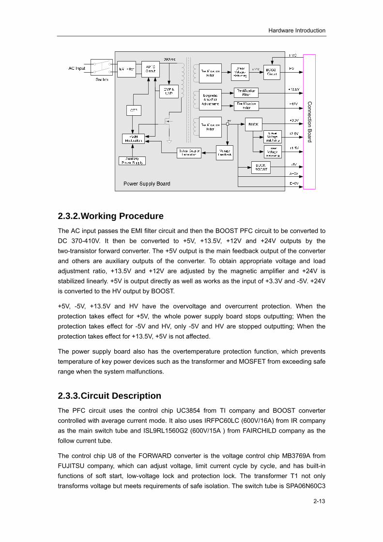
The diagram of the power supply board is shown as follows.
Hardware Introduction
2-13
Connection B
oard
2.3.2. Working Procedure The AC input passes the EMI filter circuit and then the BOOST PFC circuit to be converted to DC 370-410V. It then be converted to +5V, +13.5V, +12V and +24V outputs by the two-transistor forward converter. The +5V output is the main feedback output of the converter and others are auxiliary outputs of the converter. To obtain appropriate voltage and load adjustment ratio, +13.5V and +12V are adjusted by the magnetic amplifier and +24V is stabilized linearly. +5V is output directly as well as works as the input of +3.3V and -5V. +24V is converted to the HV output by BOOST.
+5V, -5V, +13.5V and HV have the overvoltage and overcurrent protection. When the protection takes effect for +5V, the whole power supply board stops outputting; When the protection takes effect for -5V and HV, only -5V and HV are stopped outputting; When the protection takes effect for +13.5V, +5V is not affected.
The power supply board also has the overtemperature protection function, which prevents temperature of key power devices such as the transformer and MOSFET from exceeding safe range when the system malfunctions.
2.3.3. Circuit Description The PFC circuit uses the control chip UC3854 from TI company and BOOST converter controlled with average current mode. It also uses IRFPC60LC (600V/16A) from IR company as the main switch tube and ISL9RL1560G2 (600V/15A ) from FAIRCHILD company as the follow current tube.
The control chip U8 of the FORWARD converter is the voltage control chip MB3769A from FUJITSU company, which can adjust voltage, limit current cycle by cycle, and has built-in functions of soft start, low-voltage lock and protection lock. The transformer T1 not only transforms voltage but meets requirements of safe isolation. The switch tube is SPA06N60C3
Hardware Introduction
2-14
from INFINEON company, which basic parameter is 650V/6.2A. The +5V output is the main feedback output of the FORWARD converter, +13.5V and +12V are adjusted by the magnetic amplifier, and +24V is stabilized linearly by LM317.
HV is output from the BOOST converter, which uses the voltage control chip TL594 from ONSEMI company. HV is controlled by 0-4V analog input signal and varies linearly between 30V and 140V with the variation of control signal.
+3.3V is output from the BUCK converter which is based on synchronous rectification. EL7566 from INTERSIL company works as the controller, which integrates all control and protection circuits and switch tube. Its rated output current is 6Amp and its conversion efficiency can reach 96% at most.
+2.5V and +1.5V are the outputs of +3.3V after linear voltage-stabilizing, which is performed by IRF7401 MOS from IR company and feedback control circuit. The MOS works at the amplification area to realize linear stabilizing of low voltage.
-5V is obtained from +5V through BUCK-BOOST converter, which uses the control chip TPS6755 from TI company. The chip, integrating MOS, produces negative voltage output along with external inductors, capacitors and diodes and have current limit protection for switch tube.
2.3.4. Protection Circuit The power supply board has following protection functions: PFC output overvoltage protection, output overvoltage protection, overtemperature protection, +5V/+12V/+13.5V/-5V/HV output overvoltage/overcurrent/short-circuit protection, and other short-circuit protections.
1. When PFC output overvoltage protection, overtemperature protection or +5V output overvoltage/overcurrent/short-circuit protection works, the whole power supply board stops all outputs and locks. The board does not work until the system recovers from the failure and restarts.
2. When +13.5V output overvoltage/overcurrent/short-circuit protection works, +13.5V and HV outputs stop and keep locking. +13.5V and HV cannot be output until the failure is removed and the +13.5V/+12V output load is disconnected.
3. When +12V output overvoltage/overcurrent/short-circuit protection works, the output stops and keeps locking. The +12V cannot be output until the failure is removed and the +13.5V/+12V output load is disconnected.
4. When +3.3V short-circuit protection works, +3.3V and HV outputs stop. They can recover automatically after the failure is removed.
5. When -5V overcurrent/short-circuit protection works, -5V output stops. When -5V overvoltage protection works, the output stabilizes at some voltage (>-7V) exceeding the rated voltage, not affecting other outputs, and can recover automatically after the failure is removed.
6. When HV overvoltage/overcurrent/short-circuit protection or +1.5V/+2.5V

Hardware Introduction
2-15
overcurrent/short-circuit protection works, the output stops and does not affect other outputs. They except HV can recover automatically after the failure is removed.
2.3.5. Maintenance Before test or service, connect the power supply board as the figure below shows. The electronic load A is necessary while the electronic load B is not. When adding the electronic load B, ensure the load for 390VDC does not exceed 0.1A and is added only when loads for other outputs are minimum.
You can add loads only for +5V, +13.5V, +12V and HV outputs. It is recommended to start debugging when the load is a little heavier than the minimum and to increase the load during the debug if necessary.
After connecting the board properly, you can locate the failure and service the board according to the procedure shown in the figure below. The following procedure is just a basic instruction and you should operate according to the actual situation.

Hardware Introduction
2-16
The following figures shows some waveforms which can be referred during the test and service.

Hardware Introduction
2-17
GS Voltage Waveform of Q14
Oscillation Waveform of Pin 14 of U18
Oscillation Waveform of Pin 5 of U8 DS Voltage Waveform of Q15 and Q16
Voltage Waveform of D1 Oscillation Waveform of Pin 5 of U2
DS Voltage Waveform of Q1
Voltage Waveform of U7.8

Hardware Introduction
2-18
Voltage Waveform of U1.7
In the figure of GS Voltage Waveform of Q14, the duty ratio of drive waveform varies with the AC input voltage. In the figure of DS Voltage Waveform of Q1, the amplitude of switch waveform varies with the HV output. Besides the two waveforms describes before, the amplitude, frequency and duty ratio of all waveforms tested during the service must be the same with the figures above.
Warning: Take extreme caution when testing and
servicing boards to avoid damage of measurement
devices and boards and even body injury. Never touch any
parts on boards especially the primary circuit and the high
voltage part of secondary circuit.
2.4. Principle of the LCD
2.4.1. Operating Principle of the Inverter Module The block diagram and functional diagram are shown in the following figures.

Hardware Introduction
2-19
Regulating board
PW/M control
Voltage feedback
MOSFET switch13.5V input Boost
conversion
Output to strip lamp
Current feedback
Inverter module
Brightness control
On/Off
Block Diagram of LCD Inverter
Functional Diagram of LCD Inverter
The input of the inverter module is a 13.5V DC from the regulating board. In the inverter
module, the on-off MOSFETs are connected as a bridge circuit, which implements the
on-off operations driven by the main IC and convert the input DC to high voltage AC and
then transmit to the primary winding of the transformer. The secondary square wave of
the transformer is converted to sine wave after LC resonance to drive the CCFL gives out
light. The on-off signals control the on and off of the strip lamp throuth the enabling pin of
the main IC. The brightness of the light is controlled by the brightness signal, which will
control the duty cycle of square wave of main IC.
The inverter module is configured with protection circuit of open circuit, overvoltage and

Hardware Introduction
2-20
overcurrent. Open circuit protection: When any of the strip lamps is open circuit, the
current feedback signal will be severely weak. If the feedback current does not stabilize
the CMP voltage even if the voltage of CMP rises to 3V, the IC will close two output
pulses and the circuit is locked for protection. Over current protection: When the output
current is too strong, the main IC will restrain the duty cycle of square wave after
receiving the feedback signal from the strip lamp to lower the current for protection.
Overvoltage protection: When the output voltage is too high, the main IC closes the PWM
driving after receiving the feedback signal from the strip lamp for protection.
Definitions of the output ports of strip lamp driver CN2 and CN3:
Definitions of the ports connected to CN1 and V/D board:
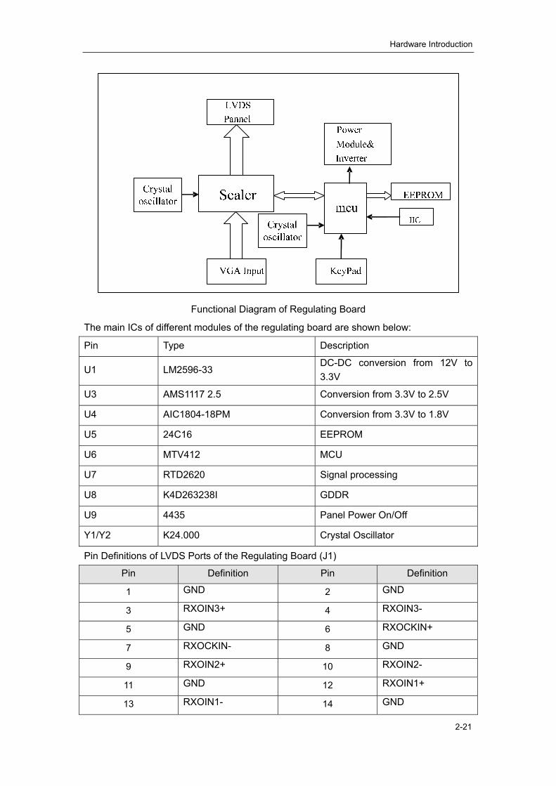
2.4.2. Working principle of the regulating board The functional block diagram of the regulating board is shown in FIG 2-21.
The VGA signal is transmitted to RTD2620 and completes the identification, amplification
and color processing. The signal is transformed to LVDS signal and then transmitted to
the LCD screen. U6 (MTV412) is MCU, which is responsible for the control of RTD 2620
and control of external operations such as buttons. U1, U3 and U4 provide working
voltage for DC-DC convert.
Pin Definition
1 Vout -H
2 Vout -L
Pin Definition
1 13.5V
2 13.5V
3 ON/OFF
4 ADJ
5 GND
6 GND
Hardware Introduction
2-21
Functional Diagram of Regulating Board
The main ICs of different modules of the regulating board are shown below:
Pin Type Description
U1 LM2596-33 DC-DC conversion from 12V to 3.3V
U3 AMS1117 2.5 Conversion from 3.3V to 2.5V
U4 AIC1804-18PM Conversion from 3.3V to 1.8V
U5 24C16 EEPROM
U6 MTV412 MCU
U7 RTD2620 Signal processing
U8 K4D263238I GDDR
U9 4435 Panel Power On/Off
Y1/Y2 K24.000 Crystal Oscillator
Pin Definitions of LVDS Ports of the Regulating Board (J1)
Pin Definition Pin Definition
1 GND 2 GND
3 RXOIN3+ 4 RXOIN3-
5 GND 6 RXOCKIN+
7 RXOCKIN- 8 GND
9 RXOIN2+ 10 RXOIN2-
11 GND 12 RXOIN1+
13 RXOIN1- 14 GND
Hardware Introduction
2-22
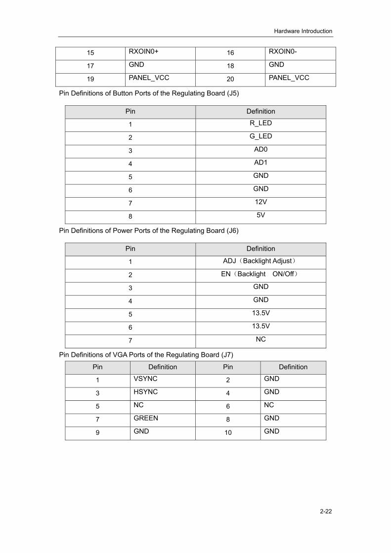
15 RXOIN0+ 16 RXOIN0-
17 GND 18 GND
19 PANEL_VCC 20 PANEL_VCC
Pin Definitions of Button Ports of the Regulating Board (J5)
Pin Definitions of Power Ports of the Regulating Board (J6)
Pin Definitions of VGA Ports of the Regulating Board (J7)
Pin Definition Pin Definition
1 VSYNC 2 GND
3 HSYNC 4 GND
5 NC 6 NC
7 GREEN 8 GND
9 GND 10 GND
Pin Definition
1 R_LED
2 G_LED
3 AD0
4 AD1
5 GND
6 GND
7 12V
8 5V
Pin Definition
1 ADJ(Backlight Adjust)
2 EN(Backlight ON/Off)
3 GND
4 GND
5 13.5V
6 13.5V
7 NC

Hardware Introduction
2-23
Pin Definitions of Power Ports of the Regulating Board (J8)
Pin Definition
1 13.5V
2 13.5V
3 GND
4 GND

3-1
Chapter 3 Disassembly of DP-9900Plus/DP-9900
3.1. System Structure
No. Part No. Name No. Part No. Name 1 9906-20-71420 Framework 11 9901-21-23941 Couplant Holder 2 9901-20-23935-51 Front Cover 12 9901-21-23942 Transducer Holder B
3 9906-30-71433 Cabinet (9906) 13 9901-20-23940 Back Cover of Neck
9905-30-71057 Cabinet (9905) 4 9904-20-37005 Right Cover 14 9901-20-23939 Top Cover 5 2100-20-08052 Drawer 15 2102-20-17125 Handle
6 2102-30-16949 Transducer Cable
Hanger 16 9906-30-71443
Air Outlet Fan Assembly
7 9901-30-23969 Keyboard Support 17 2131-30-71794 CD-ROM 8 9901-21-23942 Transducer Holder A 18 9906-30-71439 Upper Rear Cover
9 9905-30-71081 Keyboard (9905)
19 9906-30-71441 Lower Rear Cover 9906-30-71512 Keyboard (9906)

Disassembly of DP-9900Plus/DP-9900
3-2
No. Part No. Name No. Part No. Name
10 9904-30-37064 DP-9900Plus14"
Monitor 20 9904-20-37004 Left Cover
Warning: Be sure to disconnect the power supply
before disassembling any part.
3.2. Disassembly of Monitor
1. Remove the 4 M4×8 screws on the top and bottom of the monitor.
2. Release the swing bowl and let it stay around the neck.
3. Press the two clips with thumbs with two hands holding the sides of the monitor,
and simultaneously pull the rear cover backwards.
1 - M4×8 Screws 2 - Rear Cover 3 - Monitor
4. Disconnect the data line and the power cord from the monitor.
5. Remove the M5×16 screw on the bottom of the monitor.
6. Raise the monitor.
<1> Press <2> Pull

Disassembly of DP-9900Plus/DP-9900
3-3
1 - Monitor 2 - Data Line 3 - Swing Bowl 4 - Power Cord 5 - M5×16 Screw
3.3. Disassembly of Screen
1. Slide the two clips and pull them out.
2. Pull out the upper side of the screen, then raise the screen and take it out.
3.4. Disassembly of Keyboard
3.4.1. Disassembly of Keyboard Cover
1. Remove the ten M3×12 screws on the bottom of the keyboard.。
2. Raise the right side of the keyboard.
3. Remove the M3X6 screw.
4. Disconnect the data line, power cord and footswitch cable. Remove the keyboard.
<1> <1>
<2>
<2>
<3>
<4>

Disassembly of DP-9900Plus/DP-9900
3-4
1 – Data Line 2 – Power Cord 3 – Footswitch Cable 4 - M3×6 Screw 5 – Ground Wire 6 - Base 7 - Keyboard
3.4.2. Disassembly of Trackball
1. Place the keyboard face down and remove the two M2.5×16 screws.
2. Disconnect the trackball cable and raise the trackball.
M3×12 Screws
Disassembly of DP-9900Plus/DP-9900
3-5
1 – Keyboard Cover 2 - M2.5×16 Screws 3 - Trackball
3.4.3. Disassembly of Keyboard Board
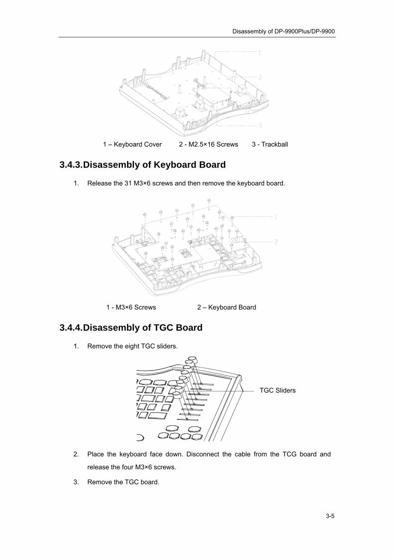
1. Release the 31 M3×6 screws and then remove the keyboard board.
1 - M3×6 Screws 2 – Keyboard Board
3.4.4. Disassembly of TGC Board
1. Remove the eight TGC sliders.
2. Place the keyboard face down. Disconnect the cable from the TCG board and
release the four M3×6 screws.
3. Remove the TGC board.
TGC Sliders

Disassembly of DP-9900Plus/DP-9900
3-6
3.5. Disassembly of CD-ROM
3.5.1. Locking Casters
1. Press the two casters on the front of the system to lock them.
3.5.2. Disassembly of Drawer and Transducer Cable Hanger
1. Release the four M4×8 screws and remove the drawer.
2. Rotate the transducer cable hanger clockwise until it can be pulled out.
M3×6 Screws
TGC Board

Disassembly of DP-9900Plus/DP-9900
3-7
1 – Transducer Cable Hanger 2 – M4×8 Screws 3 - Drawer
3.5.3. Disassembly of Rear Cover of Neck
1. Remove the two M3×8 screws and push the rear cover of neck backwards.
1 – Rear Cover of Neck 2 – M3×8 Screws
3.5.4. Disassembly of Top Cover
1. Release the two M3×8 screws and the two M4×8 screws. Then raise the top cover.

Disassembly of DP-9900Plus/DP-9900
3-8
1 – M3×8 Screws 2 – Top Cover 3 – M4×8 Screws
3.5.5. Disassembly of Left Cover
1. Release the four M4×12 screws and push the CD-ROM backwards to its end.
1 – M4×12 Screws 2 – CD-ROM
2. Release the three M4×8 screws on the left cover. Push the left cover backwards.

Disassembly of DP-9900Plus/DP-9900
3-9
1 – M4×8 Screws 2 – Left Cover
3.5.6. Disassembly of Right Cover
1. Release the three M4×8 screws. Push the right cover backwards.
1 – M4×8 Screws 2 – Right Cover
3.5.7. Disassembly of Front Cover
1. Remove the M5×10 screw on the rear of the neck and rotate the keyboard 90°

Disassembly of DP-9900Plus/DP-9900
3-10
clockwise (or counterclockwise).
2. Remove the six M4×8 screws.
3. Press the power switch and remove the front cover.
1 – Front Cover 2 – M4×8 Screws
3.5.8. Disassembly of CD-ROM Disconnect the power cable and data line from the CD-ROM. Release the four M4×12
screws from the top of the framework and remove the CD-ROM.
M5×10 Screw
Disassembly of DP-9900Plus/DP-9900
3-11
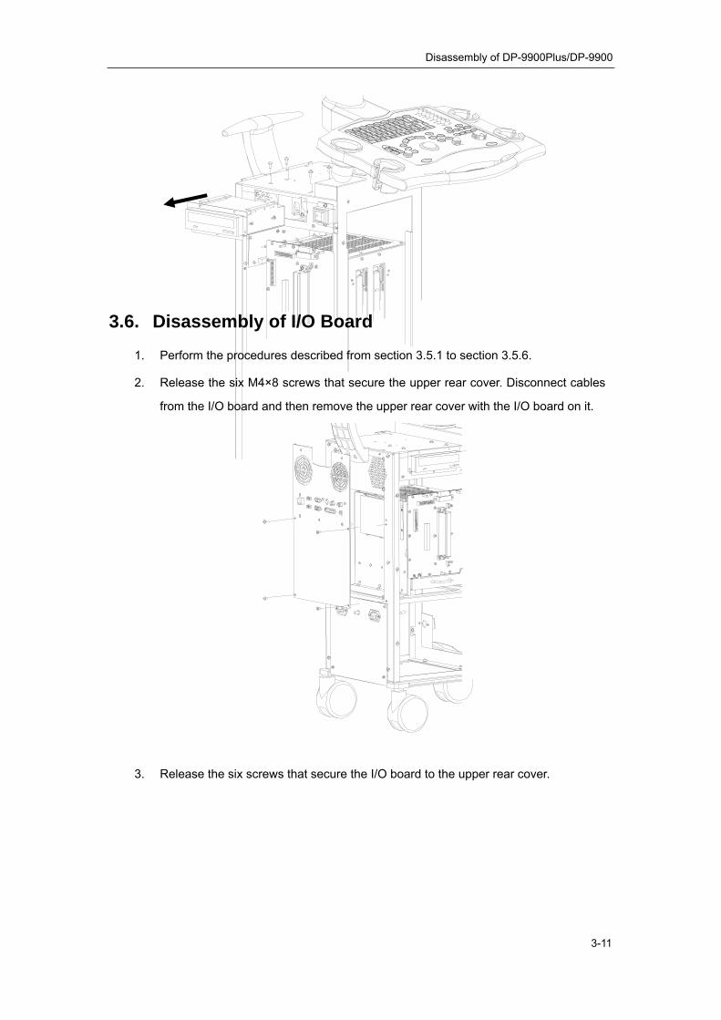
3.6. Disassembly of I/O Board
1. Perform the procedures described from section 3.5.1 to section 3.5.6.
2. Release the six M4×8 screws that secure the upper rear cover. Disconnect cables
from the I/O board and then remove the upper rear cover with the I/O board on it.
3. Release the six screws that secure the I/O board to the upper rear cover.

Disassembly of DP-9900Plus/DP-9900
3-12
3.7. Disassembly of Air Outlet Fan Assembly
1. Perform the steps 1 and 2 in section 3.6.
2. Disassemble the right cover.
3. Disassemble the upper rear cover.
4. Disconnect cables from the air outlet fan assembly and then remove the four
screws that secure the assembly.
3.8. Disassembly of Hard Disk
1. Perform the steps 1 and 2 in section 3.6..
Upper Rear Cover
I/O Board

Disassembly of DP-9900Plus/DP-9900
3-13
2. Disassemble the upper rear cover.
3. Disconnect the power cable and data line from the hard disk and then release the
four screws that secure the hard disk.
3.9. Disassembly of Power Conversion Board
1. Release the four M4×8 screws on the lower rear cover. Then disconnect cables
from the power conversion board and remove the lower rear cover with the power
conversion board on it.
2. Remove the power conversion board from the lower rear cover.

Disassembly of DP-9900Plus/DP-9900
3-14
3.10. Disassembly of Air Intake Fan Assembly
1. Perform the procedures described from section 3.5.1 to section 3.5.7.
2. Release the two M4×8 screws that secure the air intake fan assembly and pull out
the assembly by its handle.
Lower Rear Cover
Power Conversion Board
Power Output Socket
Power Input Socket
Ground Terminal

Disassembly of DP-9900Plus/DP-9900
3-15
3.11. Disassembly of Output Board, Main Board and
Power Supply Board
1. Perform the procedures described from section 3.5.1 to section 3.5.7. Disconnect
cables from the output board and remove the screws on the board. Hold the
handle on the board and remove it gently.
2. Remove the two screws from the power supply board and pull the power supply
board by its handle to disassemble it.
3. Hold the two handles on the main board and rotate them outwards to disassemble
the main board.

Disassembly of DP-9900Plus/DP-9900
3-16
3.12. Disassembly of Transducer Board
1. Perform the procedures described from section 3.5.1 to section 3.5.7.
2. Disassemble the output board.
3. Remove the eight screws that secure the transducer board shield at the front of the
cabinet. Take out the board by its handles.
3.13. Disassembly of Cabinet
1. Perform the procedures described from section 3.5.1 to section 3.5.7.
2. Disconnect the cables from the main board and the output board. Remove the six
Main Board Power Supply Board
Transducer Board

Disassembly of DP-9900Plus/DP-9900
3-17
M4×8 screws and take out the whole cabinet.
3.14. Diagram
1. Base 2. Footswitch Support 3. Framework 4. Cabinet 5. Power Switch Support 6. Shield Cover 7. Keyboard Pillar Anchor Ear 8. Transducer Cable Hanger Fixed Block 9. Keyboard Pillar Sleeve 10. Air Outlet Fan Assembly 11. Handle 12. Upper Rear Cover 13. CD-ROM 14. Hard Disk 15. Lower Rear Cover

Disassembly of DP-9900Plus/DP-9900
3-18
3.15. Disassembly of the LCD Monitor Assembly 1. Poke the lever left and rotate the monitor to horizontal position. Remove the M4X12
screws (2 pcs) securing the cable cover, and then remove the cover. (The lever
locates at left, lower corner of the back of the monitor. When the lever is on the right
side, the monitor is in working status and it can be rotated 20 degrees frontward
and 20 degrees backward. When packed for transportation or pushed around, poke
the lever to the left and you can retract the monitor.)
1. LCD assembly 2. Cable cover 3. M4X12 combination screws (2 pcs) 4. Lever
Disassembly of the LCD Module (1)
2. Remove the M4X12 combination screw (1 pcs) securing the ground wire clip, take
out the cable plug and remove the M4X12 combination screws (6 pcs) securing the
monitor.
1. LCD assembly 2. M4X12 combination screws (7 pcs)
L
R

Disassembly of DP-9900Plus/DP-9900
3-19
Disassembly of the LCD Module (2)
3. Hold the lateral sides of the monitor and raise the monitor to separate it from the
support arm hooker when the monitor is 20° from the vertical direction, and then
remove the monitor.
Disassembly of the LCD Module (3)
3.16. Replacing the OSD Board of the LCD Monitor 1. Disassemble the monitor module. (Refer to 3.15 Disassembly of the LCD Monitor
Assembly)
2. Remove the M4X12 screws (5 pcs) securing the rear cover of the monitor, and then
remove the rear cover.

Disassembly of DP-9900Plus/DP-9900
3-20
1. Front cover assembly of the LCD 2. Rear cover of the LCD 3. M4X12 combination
screws (5 pcs)
Disassembly of the OSD board (1)
3. Pull out the cable plugs from the OSD board, remove the PT3X8 screws (4 pcs)
securing the OSD board, and then remove the OSD board.
1. Front cover of the LCD 2. OSD board 3. M3X8 screws (4 pcs)
Disassembly of the OSD board (2)
3.17. Replacing the inverter board and control board
of the LCD 1. Remove the LCD assembly (refer to 3.15) and the rear cover of the LCD (refer to

Disassembly of DP-9900Plus/DP-9900
3-21
step 2 of 3.16).
2. Pull out the plugs from the OSD board of the LCD by the right side of the LCD
assembly, remove the M3X8 combination screws (10 pcs) securing the PCB
shielding cover, and then remove the PCB shielding cover.
3. Pull out the 2 plugs of the cable connecting the inverter board and the LCD, and
then pull out the plug of the cable connecting the inverter board and the control
board. Remove the M3X8 combination screws (2 pcs) securing the LCD inverter
board, and then remove the inverter board.
4. Pull out the plug of the cable connecting the inverter board and the control board,
and then pull out the plug of the cable connecting the control board and the LCD.
Remove the M3X8 combination screws (5 pcs) securing the LCD inverter board,
and then remove the control board.
1. Front cover assembly of the LCD 2. Inverter board 3. Control board 4. PCB
shielding cover 5. M3X8 combination screws (17 pcs)
Disassembly of the inverter board and the control board
3.18. Replacing the LCD screen of the LCD Monitor 1. Remove the LCD assembly (refer to 3.15) and the rear cover of the LCD (refer to
step 2 of 3.16). Pull out the plugs from the OSD board.
2. Remove the M3X8 combination screws (11 pcs) securing the LCD assembly, and

Disassembly of DP-9900Plus/DP-9900
3-22
then remove the LCD assembly.
1. Front cover assembly of the LCD 2. LCD assembly 3. M3X8 combination screws
(11 pcs)
Disassembly of the LCD screen (1)
3. Remove the M3X8 combination screws (10 pcs) securing the PCB shielding cover,
and then remove the cover. (refer to step 2 of 2.6)
4. Pull out the plugs of the cables connecting the inverter board and the LCD, and
then pull out the plug of the cable connecting the control board and the LCD. Cut off
the thread fastening the cables (3). Remove the M4X8 combination screws (6 pcs)
securing the LCD bracket and the LCD fixing bracket, and then remove the LCD
fixing bracket.

Disassembly of DP-9900Plus/DP-9900
3-23
1. LCD screen 2. LCD fixing bracket 3. M4X8 combination screws (6 pcs)
Disassembly of the LCD screen (2)
5. Remove the M3X4 panhead screws (4 pcs) securing the LCD screen and the LCD
bracket, and then remove and replace the LCD screen.
1. Screen 2. LCD bracket 3. M3X4 screws (4 pcs)
Disassembly of the LCD screen (3)
3.19. Disassembly of the LCD support arm assembly 1. Remove the LCD assembly. (refer to 3.15)
2. Remove the M4X12 combination screws (2 pcs) securing the rear cover of the
support arm, and then remove the rear cover.
1. Support arm assembly 2. Rear cover of the support arm 3. M4X12 combination
screws (2 pcs)
Disassembly of the LCD support arm assembly (1)
3. Remove the M8X25 inner hex screws (2 pcs) securing the support arm and remove

Disassembly of DP-9900Plus/DP-9900
3-24
the support arm upward.
1. Support arm assembly 2. M8X25 inner hex screws with washers 3. Fixing base for
rotation (DP-7700)
Disassembly of the LCD support arm assembly (2)

4-1
Chapter 4 Disassembly of DP-8800Plus
4.1. System Structure
No. Part No. Name No. Part No. Name 1 2102-20-16970-51 Front Cover 11 2102-21-17028 Couplant Holder 2 2131-20-71760 Framework 12 2102-30-16949 Transducer Cable
Hanger 3 2131-30-71766 Cabinet 13 2106-30-37176 Monitor 4 2102-20-16980 Printer Support 14 2102-20-16966 Top Cover 5 2102-20-16982 Printer Rear
Cover 15 2131-30-71778 I/O Board
6 2102-20-16967 Baffle Plate 16 2102-20-17125 Handle 7 2102-20-16978 Right Cover 17 2102-20-16971 Rear Cover 8 2131-30-71750 Keyboard
Support 18 9906-30-71443 Air Outlet Fan
Assembly 9 2131-30-71827 Keyboard 19 2131-30-71794 CD-ROM
Disassembly of DP-8800Plus
4-2
No. Part No. Name No. Part No. Name
10
2102-21-17024 Transducer Holder C
20
2131-30-71777 Power Socket Plate (for China)
2102-21-17026 Transducer Holder D
2131-30-71776 Power Socket Plate (Abroad)
21 2106-20-37162 Left Cover
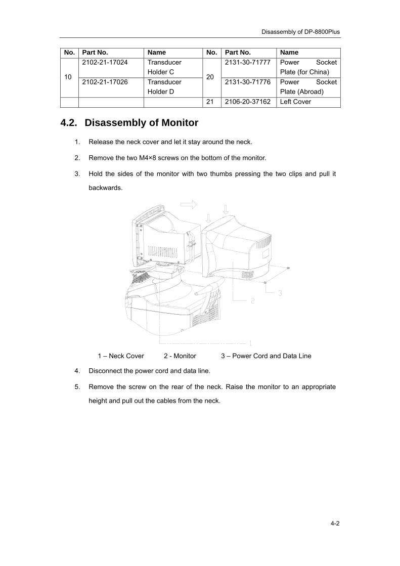
4.2. Disassembly of Monitor
1. Release the neck cover and let it stay around the neck.
2. Remove the two M4×8 screws on the bottom of the monitor.
3. Hold the sides of the monitor with two thumbs pressing the two clips and pull it
backwards.
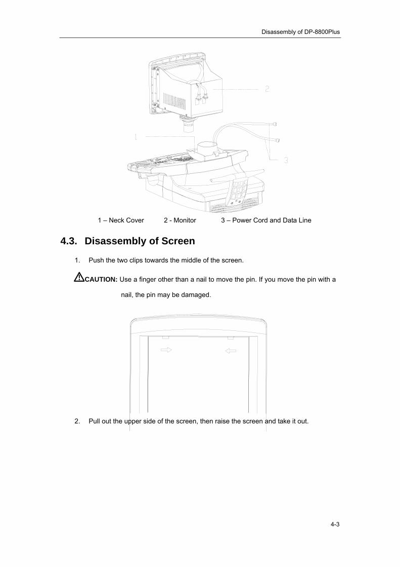
1 – Neck Cover 2 - Monitor 3 – Power Cord and Data Line
4. Disconnect the power cord and data line.
5. Remove the screw on the rear of the neck. Raise the monitor to an appropriate
height and pull out the cables from the neck.
Disassembly of DP-8800Plus
4-3
1 – Neck Cover 2 - Monitor 3 – Power Cord and Data Line
4.3. Disassembly of Screen
1. Push the two clips towards the middle of the screen.
CAUTION: Use a finger other than a nail to move the pin. If you move the pin with a
nail, the pin may be damaged.
2. Pull out the upper side of the screen, then raise the screen and take it out.
Disassembly of DP-8800Plus
4-4
1 - Screen
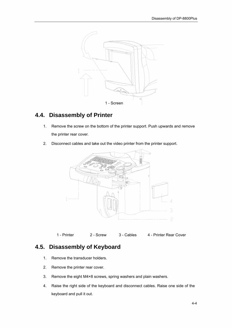
4.4. Disassembly of Printer
1. Remove the screw on the bottom of the printer support. Push upwards and remove
the printer rear cover.
2. Disconnect cables and take out the video printer from the printer support.
1 - Printer 2 - Screw 3 - Cables 4 - Printer Rear Cover
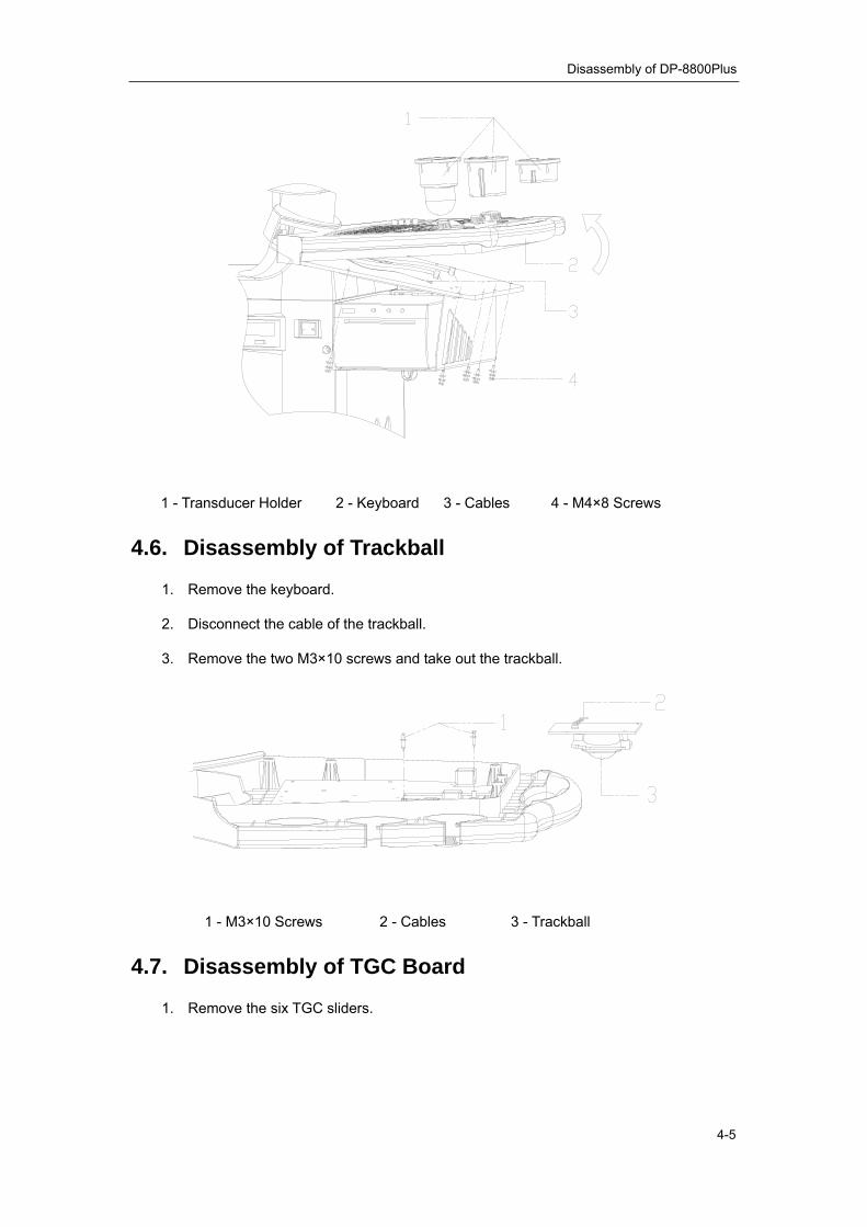
4.5. Disassembly of Keyboard
1. Remove the transducer holders.
2. Remove the printer rear cover.
3. Remove the eight M4×8 screws, spring washers and plain washers.
4. Raise the right side of the keyboard and disconnect cables. Raise one side of the
keyboard and pull it out.
Disassembly of DP-8800Plus
4-5
1 - Transducer Holder 2 - Keyboard 3 - Cables 4 - M4×8 Screws
4.6. Disassembly of Trackball
1. Remove the keyboard.
2. Disconnect the cable of the trackball.
3. Remove the two M3×10 screws and take out the trackball.
1 - M3×10 Screws 2 - Cables 3 - Trackball
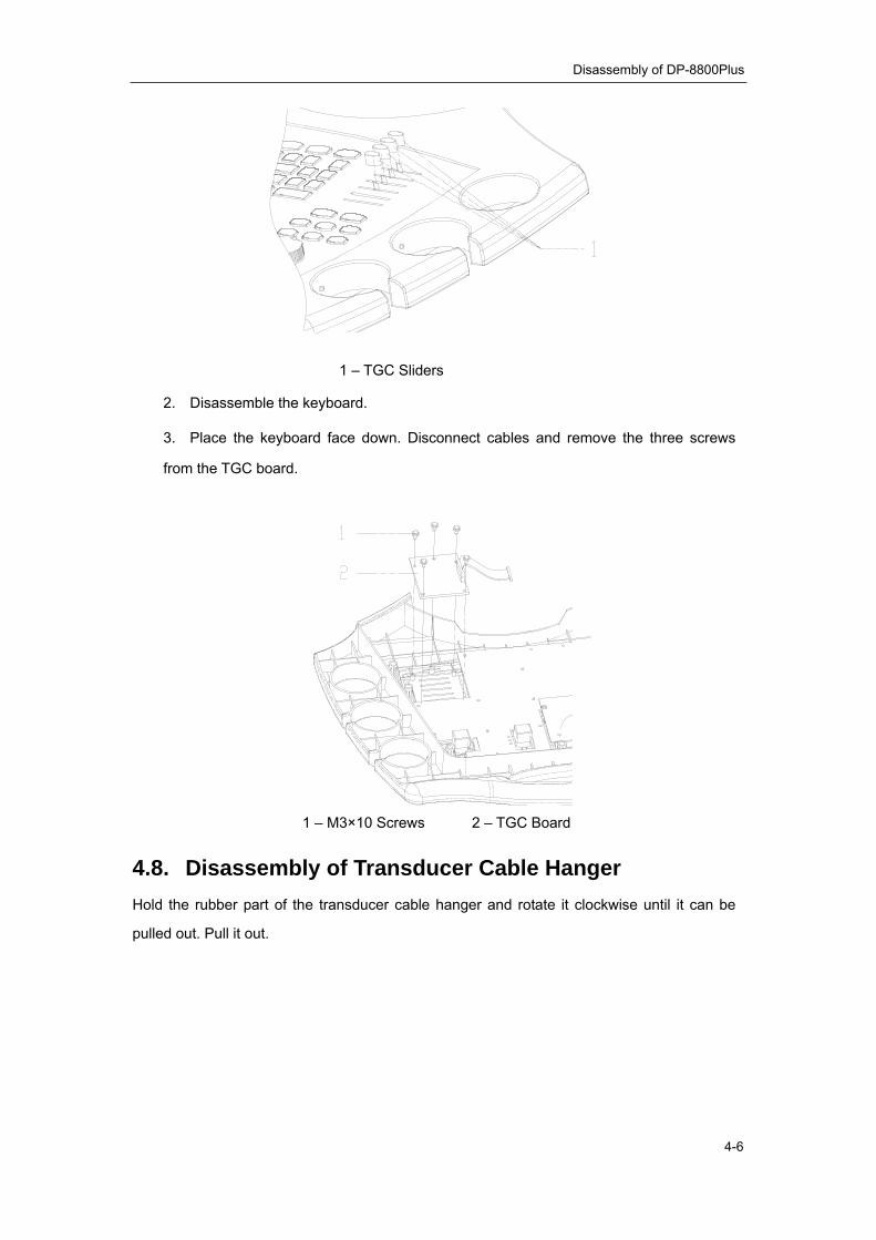
4.7. Disassembly of TGC Board
1. Remove the six TGC sliders.
Disassembly of DP-8800Plus
4-6
1 – TGC Sliders
2. Disassemble the keyboard.
3. Place the keyboard face down. Disconnect cables and remove the three screws
from the TGC board.
1 – M3×10 Screws 2 – TGC Board
4.8. Disassembly of Transducer Cable Hanger Hold the rubber part of the transducer cable hanger and rotate it clockwise until it can be
pulled out. Pull it out.

Disassembly of DP-8800Plus
4-7
1 – Transducer Cable Hanger
4.9. Disassembly of Handle 1. Remove the three M5×35 screws and washers.
2. Take off the handle.
1 - Handle 2 – M5×35 Screws

5-1
Chapter 5 Maintenance Requirements
5.1. Tools and Consumables
Tools for Maintenance and Clearing
Consumables
Consumable Model Manufacturer Specification
Insulating Tape Not Specified
Hishilite Tube (Heat-shrinkable Tube)
Insulated Conduits
Not Specified
Cables Not Specified
Screws, Nuts, Washers Not Specified
Solder Stick Not Specified
Soft Cleaning Cloth Not Specified
Glass Cleaner Not Specified
Neutral Detergent Not Specified
Ethyl Alcohol (75%) Not Specified
Tool Model Manufacturer Specification Vacuum Cleaner Not Specified Screwdrivers Not Specified Blunt Phillips Screwdriver (Queen-size) Not Specified Metal Wire Pliers Not Specified Nipper Pliers Not Specified Diagonal Cutting Pliers Not Specified Electric Iron and Holder Not Specified Desoldering Gun Not Specified Wrench Kit Not Specified Adjustable Wrench Not Specified Tweezers Not Specified Hammer Not Specified Metric General Utility Wrench Kit Not Specified Cables Not Specified Knife Not Specified Antistatic Brush Not Specified

Maintenance Requirements
5-2
Warning: 1. Never use deliquescent solvent such as paint thinner or gasoline or
abrasive cleanser to clean the system to avoid system damage. 2. Never use hydrocarbon glass cleanser or detergents cleaning OA
equipments to clean the monitor to avoid monitor performance degradation.
5.2. Maintenance Personnel
To ensure performance and safety of the system, only professional engineers from Mindray
or trained to be competent for the system maintenance can maintain the system.

6-1
Chapter 6 System Maintenance
6.1. Cleaning
6.1.1. Procedure Disconnect power cord from power socket
↓
Remove accessories
↓
Disassemble covers of main unit
↓
Clean system interior and fans
↓
Clean covers and control panel
↓
Clean monitor
↓
Clean peripherals and accessories
↓
Clean power cord and cables
6.1.2. Details
1. To clean the interior of the system and fans
Disconnect the power cord from power socket.
Remove accessories such as the transducer and printer from the system.
Disassemble the covers of the main unit.
Disassemble the air inlet fan assembly and the air outlet fan assembly from the
system and remove dust on them.
Disassemble the cabinet from the framework and remove dust in the cabinet with a
dust cleaner. Disassemble boards from the cabinet only when they fail to work.
2. To clean covers and the control panel

System Maintenance
6-2
Use a clean cloth dipped with neutral detergent to remove dust on the covers of the
main unit and on the control panel. If there is some difficulty to clean the control
panel, disassemble keys from it and then use neutral detergent to clean it.
3. To clean the monitor
Check if the monitor is skew and the fixing structure is loose. Use a dry clean cloth to
remove the dust on the monitor.
4. To clean the transducer
Use a dry clean cloth to remove dust on the transducer surface and check if there is
abnormality such as crack. Then connect it to the system. Use a soft brush to clean
the transducer holder.
5. To clean the video printer
Clean the thermal head according to the operation manual of the printer.
6. To clean cables
Use a clean cloth dipped with neutral detergent to clean the power cord and other
cables.
6.2. Software Maintenance 1. Before maintain software, ensure the data to be used matches the system to avoid
system damage and backup the preset data according to the following procedure.
a) Press [Preset] key to enter the preset menu.
b) Move the cursor to the [Preset Data] and select [Save].

System Maintenance
6-3
c) Press [Set] key. Then select the driver and the path for the saving and input file
name.
d) Move the cursor to [OK] and press [Set] key.
2. After the software maintenance, recover the preset data according to the following
procedure.
a) Press [Preset] key to enter the preset menu.
b) Move the cursor to the [Preset Data] and select [Load].

System Maintenance
6-4
c) Press [Set] key. Then select the driver and the path of the preset data file.
d) Move the cursor to [OK] and press [Set] key.
6.2.1. Software Upgrade 1. Press [Preset] key to enter the preset menu.
2. Move the cursor to [Maintenance] and press [Set] key to enter the following dialog
box. Input password into the dialog box.
3. Move the cursor to [OK] and press [Set] key to enter the maintenance menu.

System Maintenance
6-5
4. Move the cursor to the [Upgrade].
5. Move the cursor to the software or data to be upgraded, for example, [Sys SW], and
press [Set] key.
6. Select the UPG file in the directory of corresponding driver and move the cursor to
[OK] and press [Set] key to upgrade.
7. After the upgrade is completed, you can upgrade other files according to the procedure described above. After other files are upgraded, restart the system.
6.2.2. Installation/Uninstallation of DICOM Enter the maintenance menu as the procedure described in 6.2.1. Move the cursor to [Option]
and press [Set]. Then input an appropriate password to enter the following dialog box.

System Maintenance
6-6
1. To install DICOM
Move the cursor to [Installation DICOM] and press [Set] key. Select the .key file from
corresponding directory to complete the installation.
2. To uninstall DICOM
Move the cursor to [Uninstallation DICOM] and press [Set] key to uninstall DICOM.
6.2.3. System Self-check 1. Enter the maintenance menu as the procedure described in 6.2.1. Move the cursor to
[Self Test] and press [Set] key to enter the system self-check
2. View the self-check report after the self-check is completed.
3. Restart the system.
6.2.4. LCD test After the LCD monitor is installed onto the main unit, you can check the LCD screen
through the LCD test function. The operations are:
1. Press <Preset> on the control panel to open the preset menu. Click [Maintenance]
and input the maintenance password to open the maintenance menu.

System Maintenance
6-7
2. Click [Monitor Test] [LCD Monitor] in the maintenance menu.
3. The pictures displayed and the purposes are:
No. Pictures Purpose Criterion 1 Frame
test The frame is fully displayed

System Maintenance
6-8
2 Horizontal resolution power test
The vertical stripes should be clear and there is no interference when the resolution is 640*480. (The image is enlarged when the resolution is 800*600, so the strips may be a little fuzzy. It is normal. )
3 Vertical resolution power test
The horizontal stripes should be clear and there is no interference when the resolution is 640*480. (The image is enlarged when the resolution is 800*600, so the strips may be a little fuzzy. It is normal. )
4 Grey scale test
Check whether the grey scale is normal. The grey scale gets brighter from 0 to 255. There is no obvious color cast.

System Maintenance
6-9
5 Focus test
The characters are clear when the resolution is 640*480 and there is no ghost image or distortion. The image is enlarged when the resolution is 800*600, so the strips may be a little fuzzy. It is normal.
6 Focus test
The characters are clear when the resolution is 640*480 and there is no ghost image or distortion. The image is enlarged when the resolution is 800*600, so the strips may be a little fuzzy. It is normal.
7 Focus test

System Maintenance
6-10
8 Bad dot test (black)
There is no bright dot in the whole screen.
9
Bad dot test (white)
The adjoining dark dots are no more than 3 pairs, and there is no adjoining dark dots in image area. There is no adjoining dark dots of 3 or more than 3. The dark dots are no more than 7 and those in the image area are no more than 2 There is no flickering dot. The distance between bad dots is no less than 5mm.

7-1
Chapter 7 Troubleshooting
7.1. Power Supply No. Symptom Possible Cause Solution
1 The power indicator does not light up after the power switch is turned on.
The power supply unit of the system does not work properly or the power cord is not connected properly.
Check the power supply unit and the power cord.
2 The power indicator is on but no image appears.
1. The interval between the shutdown and restart is too short.
2. The contrast or brightness of the monitor is abnormal.
1. Restart the system 1 minute after the shutdown.
2. Adjust the monitor with its contrast and brightness buttons.
7.2. Monitor Note: If nothing is displayed on the monitor, check the contrast and brightness of the monitor
and adjust them to medium values. If the monitor is still abnormal, perform according to the following table.
No. Symptom Possible Cause Solution
1 No display and the monitor indicator is off.
The power supply of the monitor fails.
Check the power cord of the monitor.
2 No display and the monitor indicator is on.
1. Monitor signal is wrong.
2. Setting is wrong or the main board fails.
1. Check the data line.
2. Check the connection to the output board.
3. Check the contrast and brightness buttons.
4. Replace the main board.
4 Abnormal image Monitor signal is wrong. Check the data line.
5 The screen flickers. Monitor signal is wrong or the monitor fails.
1. Check the data line.
2. Replace the monitor.

Troubleshooting
7-2
7.3. Troubleshooting of LCD Blank Screen
Does the system succeed to boot?
Blank screen
N
Work flow of boot failure
Remove the rear cover of the LCD and test
whether the line-field and VGA signal are
OK
Y
Y
Are the connections of LCD power cord and VGA signal
cable OK?
Y
Replace the LCD assembly
Reconnect or replace the
cables
Blank screen?Y
N
Check whether the other end of the
VGA cable is OKN
End
N
Replace the main board
Y
End
Reconnect or replace the
cables N
7.4. Troubleshooting of Other Malfunctions of the LCD No. Malfunction Potential Causes Measures 1 The image is located in
the wrong area, or lateral and vertical strips appear on the image.
The signal is interfered abnormally
Try Auto Adjust under the image without boundary.
2 The image color is abnormal.
The signal is interfered abnormally
Try Auto Color under the black/ white image.
3 There is signal input, but nothing displayed on the screen.
The LVDS cable may be loose
Check the socket of the back-light board, check whether LVDS is connected well with PANEL, and whether LVDS is properly connected with J1 socket of
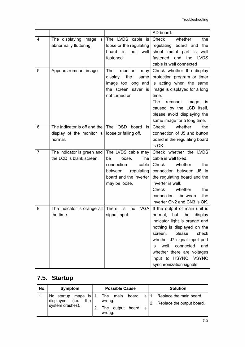
Troubleshooting
7-3
AD board. 4 The displaying image is
abnormally fluttering. The LVDS cable is loose or the regulating board is not well fastened
Check whether the regulating board and the sheet metal part is well fastened and the LVDS cable is well connected
5 Appears remnant image. The monitor may display the same image too long and the screen saver is not turned on
Check whether the display protection program or timer is acting when the same image is displayed for a long time. The remnant image is caused by the LCD itself, please avoid displaying the same image for a long time.
6 The indicator is off and the display of the monitor is normal.
The OSD board is loose or falling off.
Check whether the connection of J5 and button board in the regulating board is OK.
7 The indicator is green and the LCD is blank screen.
The LVDS cable may be loose. The connection cable between regulating board and the inverter may be loose.
Check whether the LVDS cable is well fixed. Check whether the connection between J6 in the regulating board and the inverter is well. Check whether the connection between the inverter CN2 and CN3 is OK.
8 The indicator is orange all the time.
There is no VGA signal input.
If the output of main unit is normal, but the display indicator light is orange and nothing is displayed on the screen, please check whether J7 signal input port is well connected and whether there are voltages input to HSYNC, VSYNC synchronization signals.
7.5. Startup No. Symptom Possible Cause Solution
1 No startup image is displayed (i.e. the system crashes).
1. The main board is wrong.
2. The output board is wrong.
1. Replace the main board.
2. Replace the output board.
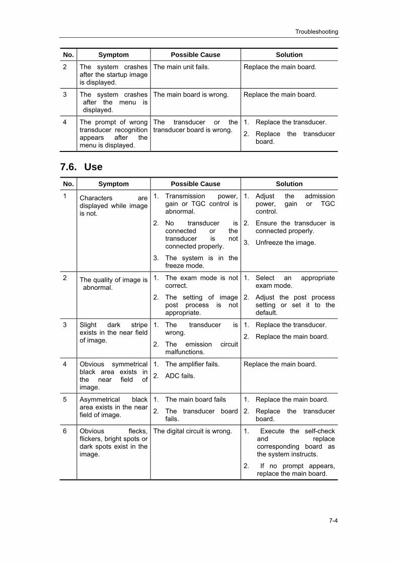
Troubleshooting
7-4
No. Symptom Possible Cause Solution
2 The system crashes after the startup image is displayed.
The main unit fails. Replace the main board.
3 The system crashes after the menu is displayed.
The main board is wrong. Replace the main board.
4 The prompt of wrong transducer recognition appears after the menu is displayed.
The transducer or the transducer board is wrong.
1. Replace the transducer.
2. Replace the transducer board.
7.6. Use No. Symptom Possible Cause Solution
1 Characters are displayed while image is not.
1. Transmission power, gain or TGC control is abnormal.
2. No transducer is connected or the transducer is not connected properly.
3. The system is in the freeze mode.
1. Adjust the admission power, gain or TGC control.
2. Ensure the transducer is connected properly.
3. Unfreeze the image.
2 The quality of image is abnormal.
1. The exam mode is not correct.
2. The setting of image post process is not appropriate.
1. Select an appropriate exam mode.
2. Adjust the post process setting or set it to the default.
3 Slight dark stripe exists in the near field of image.
1. The transducer is wrong.
2. The emission circuit malfunctions.
1. Replace the transducer.
2. Replace the main board.
4 Obvious symmetrical black area exists in the near field of image.
1. The amplifier fails.
2. ADC fails.
Replace the main board.
5 Asymmetrical black area exists in the near field of image.
1. The main board fails
2. The transducer board fails.
1. Replace the main board.
2. Replace the transducer board.
6 Obvious flecks, flickers, bright spots or dark spots exist in the image.
The digital circuit is wrong. 1. Execute the self-check and replace corresponding board as the system instructs.
2. If no prompt appears, replace the main board.
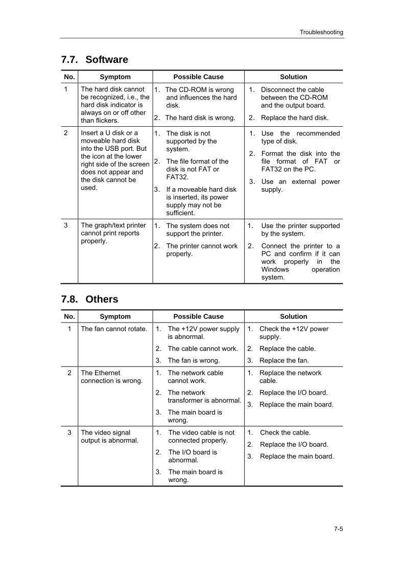
Troubleshooting
7-5
7.7. Software No. Symptom Possible Cause Solution
1 The hard disk cannot be recognized, i.e., the hard disk indicator is always on or off other than flickers.
1. The CD-ROM is wrong and influences the hard disk.
2. The hard disk is wrong.
1. Disconnect the cable between the CD-ROM and the output board.
2. Replace the hard disk.
2 Insert a U disk or a moveable hard disk into the USB port. But the icon at the lower right side of the screen does not appear and the disk cannot be used.
1. The disk is not supported by the system.
2. The file format of the disk is not FAT or FAT32.
3. If a moveable hard disk is inserted, its power supply may not be sufficient.
1. Use the recommended type of disk.
2. Format the disk into the file format of FAT or FAT32 on the PC.
3. Use an external power supply.
3 The graph/text printer cannot print reports properly.
1. The system does not support the printer.
2. The printer cannot work properly.
1. Use the printer supported by the system.
2. Connect the printer to a PC and confirm if it can work properly in the Windows operation system.
7.8. Others No. Symptom Possible Cause Solution
1 The fan cannot rotate. 1. The +12V power supply is abnormal.
2. The cable cannot work.
3. The fan is wrong.
1. Check the +12V power supply.
2. Replace the cable.
3. Replace the fan.
2 The Ethernet connection is wrong.
1. The network cable cannot work.
2. The network transformer is abnormal.
3. The main board is wrong.
1. Replace the network cable.
2. Replace the I/O board.
3. Replace the main board.
3 The video signal output is abnormal.
1. The video cable is not connected properly.
2. The I/O board is abnormal.
3. The main board is wrong.
1. Check the cable.
2. Replace the I/O board.
3. Replace the main board.

Troubleshooting
7-6
No. Symptom Possible Cause Solution
4 The control panel has no response when it is operated.
1. The software fails.
2. The power cord of the control panel cannot work.
3. The serial port cable of the control panel cannot work.
4. The control panel is wrong.
1. Restart the system.
2. Replace the power cord of the control panel.
3. Replace the serial port cable of the control panel.
4. Replace the control panel.
5 The trackball has no response when it is turned.
1. The software fails.
2. The connection cable of the trackball cannot work.
3. The trackball is wrong.
1. Restart the system.
2. Replace the connection cable of the trackball.
3. Replace the trackball.

Electrical Safety Inspection
A-1
Appendix A Electrical Safety Inspection The following electrical safety tests are recommended as part of a comprehensive preventive
maintenance program. They are a proven means of detecting abnormalities that, if undetected, could prove dangerous to either the patient or the operator. Additional tests may be required according to local regulations.
All tests can be performed using commercially available safety analyzer test equipment. These procedures assume the use of a 601PROXL International Safety Analyzer or equivalent safety analyzer. Other popular testers complying with IEC 60601-1 used in Europe such as Fluke, Metron, or Gerb may require modifications to the procedure. Follow the instructions of the analyzer manufacturer.
The consistent use of a safety analyzer as a routine step in closing a repair or upgrade is emphasized as a mandatory step if an approved agency status is to be maintained. The safety analyzer also proves to be an excellent troubleshooting tool to detect abnormalities of line voltage and grounding, as well as total current loads.

Electrical Safety Inspection
A-2
ELECTRICAL SAFETY INSPECTION 1- Power Cord Plug
TEST PROCEDURE
The Power Plug
The Power Plug Pins No broken or bent pin. No discolored pins.
The Plug Body No physical damage to the plug body.
The Strain Relief No physical damage to the strain relief. No plug warmth for device in use.
The Power Plug No loose connections.
The Power Cord
The Power Cord
No physical damage to the cord. No deterioration to the cord.
‐‐For devices with detachable power cords, inspect the connection at the device.
‐‐For devices with non‐detachable power cords, inspect the strain relief at the device.
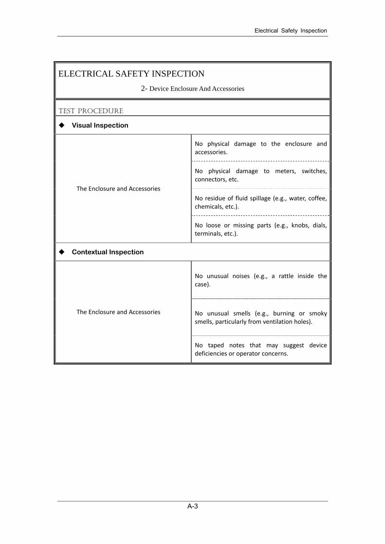
Electrical Safety Inspection
A-3
ELECTRICAL SAFETY INSPECTION 2- Device Enclosure And Accessories
TEST PROCEDURE
Visual Inspection
The Enclosure and Accessories
No physical damage to the enclosure and accessories.
No physical damage to meters, switches, connectors, etc.
No residue of fluid spillage (e.g., water, coffee, chemicals, etc.).
No loose or missing parts (e.g., knobs, dials, terminals, etc.).
Contextual Inspection
The Enclosure and Accessories
No unusual noises (e.g., a rattle inside the case).
No unusual smells (e.g., burning or smoky smells, particularly from ventilation holes).
No taped notes that may suggest device deficiencies or operator concerns.

Electrical Safety Inspection
A-4
ELECTRICAL SAFETY INSPECTION 3- Device Labeling
TEST PROCEDURE Check the labels provided by the manufacturer or the healthcare facility are present and
legible. Main Unit Label Integrated Warning Labels Slope and High Voltage Caution Label Don’t Stress Label

Electrical Safety Inspection
A-5
ELECTRICAL SAFETY INSPECTION 4- Protective Earth Resistance
VOERVIEW
Protective Earth Resistance is measured using the RED test lead attached to the DUT Protective Earth terminal or enclosure. Select the test current by pressing SOFT KEY 3 to toggle between 1AMP, 10AMP, and 25AMP. The front panel outlet power is turned off for this test.
The following conditions apply: L1 and L2 Open.
TEST PROCEDURE
Prepare
1) First select the test current that will be used for performing the Protective Earth Resistance test by pressing AMPERES (SOFT KEY 3).
2) Connect the test lead(s) between the RED input jack and the GREEN input jack.
3) Press CAL LEADS. The 601PRO will measure the lead resistance, and if less than 0.150 Ohms, it will store the reading and subtract it from all earth resistance readings taken at the calibrated current.
4) If the calibration fails, the previously stored readings will be used until a passing calibration has occurred.
WARNING
During Earth Resistance testing, the DUT must be plugged into the 601PRO front outlet. If the DUT fails Earth Resistance, discontinue tests and label the device defective.
Perform the Test
1) From the MAIN MENU, or with the outlet unpowered, plug the DUT into the 601PRO front panel outlet.
2) Attach the 601PRO RED input lead to the device’s Protective Earth terminal or an exposed metal area.

Electrical Safety Inspection
A-6
ELECTRICAL SAFETY INSPECTION 4- Protective Earth Resistance
3) Press shortcut key 3. The Protective Earth Resistance test is displayed.
4) Press SOFT KEY 3 to select a test current (1AMP, 10AMP, or 25AMP). The selected test current is displayed in the upper right corner of the display.
5) Press START TEST to start the test. The test current is applied while resistance and current readings are taken. This takes approximately 5 seconds.
6) Press the print data key at any time to generate a printout of the latest measurement(s).
Note
When "Over" is displayed for Ohms, this signifies that a valid measurement was not obtained because either an open connection was detected or that the measurement was not within range. Readings greater than 9.999 Ohms will be displayed as Over.
Failure
Once it reaches the limitation, stop using and inform the Customer Service Engineer for analysis and disposal.
LIMITS
ALL COUNTRIES R = 0.2Ω Maximum

Electrical Safety Inspection
A-7
ELECTRICAL SAFETY INSPECTION 5- Earth Leakage Test
OVERVIEW
Run an Earth Leakage test on the device being tested before performing any other leakage tests.
Leakage current is measured the following ways:
♦ Earth Leakage Current, leakage current measured through DUT outlet Earth
♦ Earth Leakage Current AP‐EARTH (ALL Applied Parts connected to Earth), leakage current measured through DUT outlet Earth
There is no need to attach a test lead; the 601PRO automatically connects the measuring device internally.
TEST PROCEDURE
Perform the Test
1) From the MAIN MENU, or with the outlet unpowered, plug the DUT into the 601PRO front panel outlet, and turn on the device.
2) Attach the device's applied parts to the 601PRO applied part terminals if applicable. 3) Press shortcut key 4.The Earth Leakage test appears on the display, and the test begins
immediately:
SOFT KEY 1 toggles the DUT outlet Polarity from Normal to Off to Reverse. SOFT KEY 2 toggles the DUT outlet from Earth to No Earth. SOFT KEY 3 toggles the DUT outlet from L2 to No L2. SOFT KEY 4 toggles the AP to Earth to No AP to Earth.
4) Press the print data key at any time to generate a printout of the latest measurement.
Failure
Check any broken of the AC/DC adapter and its cable. Replace a new one if any portion defective.
Check any broken of the enclosure. Replace any defective part.
Inspect wiring for bad crimps, poor connections, or damage.
Test the wall outlet; verify it is grounded and is free of other wiring abnormalities. Notify the
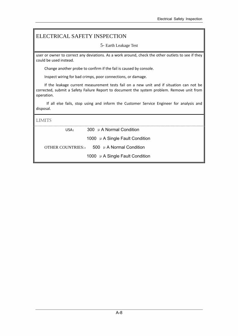
Electrical Safety Inspection
A-8
ELECTRICAL SAFETY INSPECTION 5- Earth Leakage Test
user or owner to correct any deviations. As a work around, check the other outlets to see if they could be used instead.
Change another probe to confirm if the fail is caused by console.
Inspect wiring for bad crimps, poor connections, or damage.
If the leakage current measurement tests fail on a new unit and if situation can not be corrected, submit a Safety Failure Report to document the system problem. Remove unit from operation.
If all else fails, stop using and inform the Customer Service Engineer for analysis and disposal.
LIMITS
USA: 300 μA Normal Condition
1000 μA Single Fault Condition
OTHER COUNTRIES:: 500 μA Normal Condition
1000 μA Single Fault Condition

Electrical Safety Inspection
A-9
ELECTRICAL SAFETY INSPECTION 6- Patient Leakage Current
OVERVIEW
Patient leakage currents are measured between a selected applied part and mains earth. All measurements may have either a true RMS or a DC‐only response.
TEST PROCEDURE
Prepare
Perform a calibration from the Mains on Applied Part menu.
The following outlet conditions apply when performing this test:
Normal Polarity, Earth Open, Outlet ON Normal Polarity, Outlet ON
Normal Polarity, L2 Open, Outlet ON Reversed Polarity, Outlet ON
Reversed Polarity, Earth Open, Outlet ON Reversed Polarity, L2 Open, Outlet ON
WARNING
If all of the applied parts correspond to the instrument type, the applied parts will be tied together and one reading will be taken. If any of the applied parts differ from the instrument type, all applied parts will be tested individually, based on the type of applied part. This applies to Auto and Step modes only.
Perform the Test
1) From the MAIN MENU, or with the outlet unpowered, plug the DUT into the 601PRO front panel outlet, and turn on the device.
2) Attach the applied parts to the 601PRO's applied part terminals.
3) Press shortcut key 6. The Patient Leakage test is displayed, and the test begins immediately.
4) Press APPLIED PART (SOFT KEY 4) at any time to select the desired applied part leakage current.

Electrical Safety Inspection
A-10
ELECTRICAL SAFETY INSPECTION 6- Patient Leakage Current
5) Modify the configuration of the front panel outlet by pressing the appropriate SOFT KEY on the 601PRO.
6) Press the print data key at any time to generate a printout of the latest measurement.
Note
If the current test standard being used does not include Patient Leakage DC readings, or the DC option is not enabled, then DC readings will not be available through the APPLIED PART SOFT KEY selections. Refer to Chapter 8, Standards and Principles.
Failure
Check any broken of the AC/DC adapter and its cable. Replace a new one if any portion defective.
Check any broken of the enclosure. Replace any defective part.
Inspect wiring for bad crimps, poor connections, or damage.
Test the wall outlet; verify it is grounded and is free of other wiring abnormalities. Notify the user or owner to correct any deviations. As a work around, check the other outlets to see if they could be used instead.
Change another probe to confirm if the fail is caused by console.
Inspect wiring for bad crimps, poor connections, or damage.
If the leakage current measurement tests fail on a new unit and if situation can not be corrected, submit a Safety Failure Report to document the system problem. Remove unit from operation.
If all else fails, stop using and inform the Customer Service Engineer for analysis and disposal.
LIMITS
USA:
For ECG Input and ECG Input and transducer
10μA Normal Condition
50μA Single Fault Condition
OTHER COUNTRIES:
For ECG Input(Defibrillator proof)
10μA Normal Condition
50μA Single Fault Condition
For ECG Input and transducer
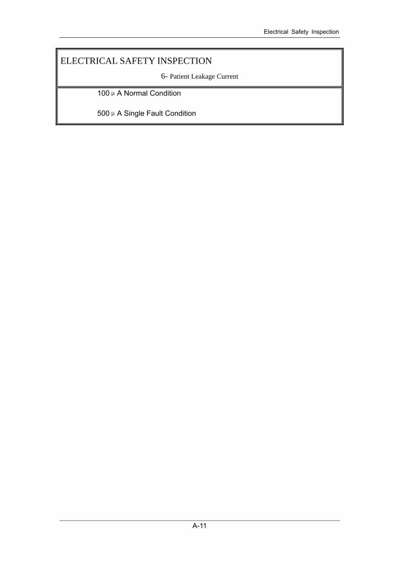
Electrical Safety Inspection
A-11
ELECTRICAL SAFETY INSPECTION 6- Patient Leakage Current
100μA Normal Condition
500μA Single Fault Condition
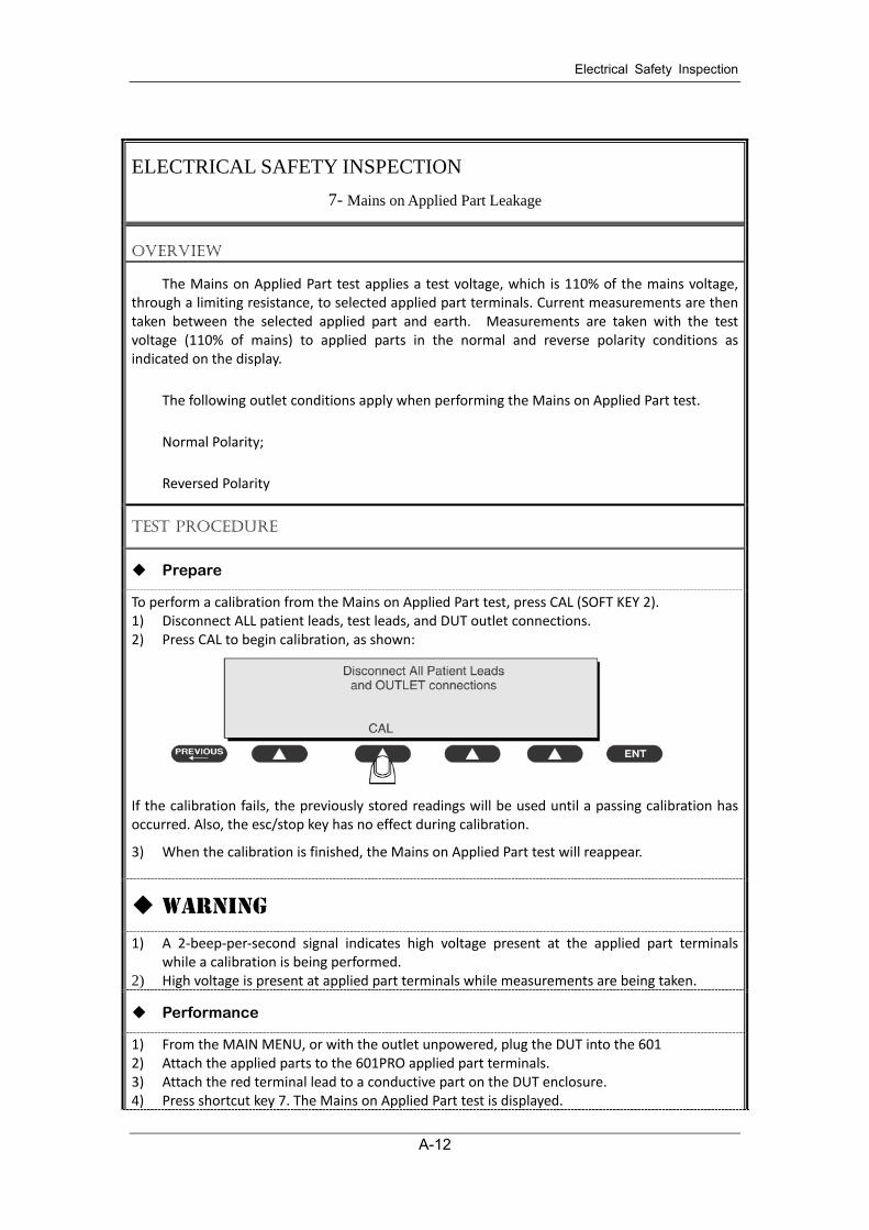
Electrical Safety Inspection
A-12
ELECTRICAL SAFETY INSPECTION 7- Mains on Applied Part Leakage
OVERVIEW
The Mains on Applied Part test applies a test voltage, which is 110% of the mains voltage, through a limiting resistance, to selected applied part terminals. Current measurements are then taken between the selected applied part and earth. Measurements are taken with the test voltage (110% of mains) to applied parts in the normal and reverse polarity conditions as indicated on the display.
The following outlet conditions apply when performing the Mains on Applied Part test.
Normal Polarity;
Reversed Polarity
TEST PROCEDURE
Prepare
To perform a calibration from the Mains on Applied Part test, press CAL (SOFT KEY 2). 1) Disconnect ALL patient leads, test leads, and DUT outlet connections. 2) Press CAL to begin calibration, as shown:
If the calibration fails, the previously stored readings will be used until a passing calibration has occurred. Also, the esc/stop key has no effect during calibration.
3) When the calibration is finished, the Mains on Applied Part test will reappear.
WARNING
1) A 2‐beep‐per‐second signal indicates high voltage present at the applied part terminals while a calibration is being performed.
2) High voltage is present at applied part terminals while measurements are being taken.
Performance
1) From the MAIN MENU, or with the outlet unpowered, plug the DUT into the 601 2) Attach the applied parts to the 601PRO applied part terminals. 3) Attach the red terminal lead to a conductive part on the DUT enclosure. 4) Press shortcut key 7. The Mains on Applied Part test is displayed.

Electrical Safety Inspection
A-13
ELECTRICAL SAFETY INSPECTION 7- Mains on Applied Part Leakage
5) Select the desired outlet configuration and applied part to test using the appropriate SOFT
KEYS: 6) Press START TEST (SOFT KEY 1) to begin the test. 7) Press the print data key to generate a printout of the latest measurement.
Note
If all of the applied parts correspond to the instrument type, the applied parts will be tied together and one reading will be taken. If any of the applied parts differ from the instrument type, all applied parts will be tested individually, based on the type of applied part. This applies to Auto and Step modes only.
Failure
Check any broken of the AC/DC adapter and its cable. Replace a new one if any portion defective.
Check any broken of the enclosure. Replace any defective part.
Inspect wiring for bad crimps, poor connections, or damage.
Test the wall outlet; verify it is grounded and is free of other wiring abnormalities. Notify the user or owner to correct any deviations. As a work around, check the other outlets to see if they could be used instead.
Change another probe to confirm if the fail is caused by console.
Inspect wiring for bad crimps, poor connections, or damage.
If the leakage current measurement tests fail on a new unit and if situation can not be corrected, submit a Safety Failure Report to document the system problem. Remove unit from operation.
If all else fails, stop using and inform the Customer Service Engineer for analysis and disposal.
LIMITS
USA:
For ECG Input and ECG Input and transducer
50μA
OTHER COUNTRIES:

Electrical Safety Inspection
A-14
ELECTRICAL SAFETY INSPECTION 7- Mains on Applied Part Leakage
For ECG Input
50μA
For ECG Input and transducer
5000μA

Electrical Safety Inspection
A-15
ELECTRICAL SAFETY INSPECTION 8- Patient Auxiliary Current
OVERVIEW
Patient Auxiliary currents are measured between any selected ECG jack and the remaining selected ECG jacks. All measurements may have either a true RMS or a DC‐only response.
TEST PROCEDURE
Prepare
1) From the MAIN MENU, or with the outlet unpowered, plug the DUT into the 601PRO front panel outlet, and turn on the device.
2) Attach the patient leads to the 601PRO ECG jacks. 3) Define the Lead Types from the View Settings Option (refer to: Lead Type Definitions in
Section 5 of this chapter). 4) Press shortcut key 8. The Patient Auxiliary Current test is displayed, and the test begins
immediately. Display values are continuously updated until another test is selected.
5) Press SOFT KEYS 1‐4 to select leakage tests 6) Press APPLIED PART (SOFT KEY 4) at any time to select the desired applied part leakage
current: 7) Modify the configuration of the front panel outlet by pressing the appropriate SOFT KEY on
the 601PRO: 8) Press the print data key at any time to generate a printout of the latest measurement.
Note
If the current test standard being used does not include Patient Auxiliary Current DC readings, or the DC option is not enabled, then DC readings will not be available through the APPLIED PART SOFT KEY selections.
Failure
Check any broken of the AC/DC adapter and its cable. Replace a new one if any portion defective.
Check any broken of the enclosure. Replace any defective part.
Inspect wiring for bad crimps, poor connections, or damage.
Test the wall outlet; verify it is grounded and is free of other wiring abnormalities. Notify the user or owner to correct any deviations. As a work around, check the other outlets to see if they

Electrical Safety Inspection
A-16
ELECTRICAL SAFETY INSPECTION 8- Patient Auxiliary Current
could be used instead.
Change another probe to confirm if the fail is caused by console.
Inspect wiring for bad crimps, poor connections, or damage.
If the leakage current measurement tests fail on a new unit and if situation can not be corrected, submit a Safety Failure Report to document the system problem. Remove unit from operation.
If all else fails, stop using and inform the Customer Service Engineer for analysis and disposal.
LIMITS
USA:
For ECG Input and ECG Input and transducer
10μA Normal Condition
50μA Single Fault Condition
OTHER COUNTRIES:
For ECG Input
10μA Normal Condition
50μA Single Fault Condition
For ECG Input
100μA Normal Condition
500μA Single Fault Condition

Electrical Safety Inspection
A-17
ELECTRICAL SAFETY INSPECTION 9- Functional test
TEST PROCEDURE
9.1 Power Check that the breaker can be normally
turned on or off.
9.2 Monitor
Check if the color is pure, the image is clear and intact; the brightness is moderate; there is no defocusing and the image is not dithering.
9.3 The Touch Screen Check if keys on the touch screen of each
exam mode can respond normally.
9.4 Control Panel Check that the keys can normally work as per
the order of left to right and up to down.
Check that the Trackball can normally work.
9.5 Displayed Time and Date Check that the displayed time and date are
correct. If not, correct them.
9.6 General Operations
Check that the Freeze key can freeze or unfreeze an image.
Check that the gain key can normally work.
Check that the B, M, PW, CS, Color, 3D, 4D modes can be normally switched.
9.7 Measurement
Pressing the Freeze key can enter the freeze status, and pressing the Measure key can enter the measurement status.
Measure the vertical distance and horizontal distance to confirm that the trackball can normally work.
9.8 The Peripherals
Check that the CD can normally eject.
Check the USB device can be operated normally.
Press the Freeze key to enter the freeze status, and pressing the Print key to check the Video

Electrical Safety Inspection
A-18
ELECTRICAL SAFETY INSPECTION 9- Functional test
printer and Text printer can work normally.
9.9 Probe sockets & Probes Check that the transducer can be normally
disconnected, and it can normally work after connected to the socket.
9.10 Casters Check the casters can be locked and unlocked
normally.
9.11 The Fans
Turn on the power of the main unit and check that the fan installed on it is running smoothly.
Check that the fan doesn’t give abnormal sound when running.

ELECTRICAL SAFETY INSPECTION FORM
American version
Overall assessment:
Scheduled inspection Test item: 1, 2, 3, 9
Unopened repair type Test item: 1, 2, 3, 9
Opened repair type, not modify the power part
including transformer or patient circuit board
Test item: 1, 2, 3, 4, 5, 9
Opened repair type, modify the power part
including transformer or patient circuit board
Test item: 1, 2, 3, 4, 5, 6, 7, 8, 9
Location Technician
Equipment Control Number
Manufacturer Model SN
Measurement equipment /SN Date of Calibration
INSPECTION AND TESTING Pass/Fail Comments
1 Power Cord Plug
2 Device Enclosure and Accessories
3 Device Labeling
4 Protective Earth Resistance Ω Limit 0.2 Ω
5 Earth Leakage — — Limit
NC:300μA
SFC:1000μA Normal condition(NC) μA
Single Fault condition(SFC) μA
6* Patient Leakage Current — — Limit
NC:10μA,
SFC: 50μA Normal condition(NC) μA
Single Fault condition(SFC) μA
7* Mains on Applied Part Leakage Limit 50μA
8* Patient Auxiliary Current — — Limit
NC:10μA,
SFC: 50μA Normal condition(NC)
Single Fault condition(SFC)
9 Functional test (parameters tested):
Note: The test items marked “*” are needed only for incoming inspections and after repairs or
modifications that may have affected lead leakage [NFPA 99 (2005)8.5.2.1.3].
Deficiency / Note:
Name: _____________________________ Date / Signature: _________________________________

ELECTRICAL SAFETY INSPECTION FORM
International version
Overall assessment:
Scheduled inspection Test item: 1, 2, 3, 9
Unopened repair type Test item: 1, 2, 3, 9
Opened repair type, not modify the power part
including transformer or patient circuit board
Test item: 1, 2, 3, 4, 5, 9
Opened repair type, modify the power part
including transformer or patient circuit board
Test item: 1, 2, 3, 4, 5, 6, 7, 8, 9
Location Technician
Equipment Control Number
Manufacturer Model SN
Measurement equipment /SN Date of Calibration
INSPECTION AND TESTING Pass/Fail Comments
1 Power Cord Plug
2 Device Enclosure and Accessories
3 Device Labeling
4 Protective Earth Resistance Ω Limit 0.2 Ω
5 EARTH Leakage — — Limit
NC:500μA
SFC:1000μA Normal condition(NC) μA
Single Fault condition(SFC) μA
6* Patient Leakage Current
— — Limit
CF AP
NC:10μA, SFC: 50μA
BF AP
NC:100μA,SFC: 500μA
Normal condition(NC)
μA
Single Fault condition(SFC) μA
7* Mains on Applied Part Leakage Limit
CF AP: 50μA
BF AP: 5000μA
8* Patient Auxiliary Current
— — Limit
CF AP
NC:10μA,SFC: 50μA
BF AP
NC:100μA,SFC: 500μA
Normal condition(NC)
Single Fault condition(SFC)
9 Functional test (parameters tested):
Note: The test items marked “*” are needed only for incoming inspections and after repairs or
modifications that may have affected lead leakage [NFPA 99 (2005)8.5.2.1.3].
Deficiency / Note:
Name: _____________________________ Date / Signature: _________________________________

P/N: 9906-20-71458 (V3.0)


