40
Mindray Patient Data Share Solution Guide
Mindray Patient Data Share
Solution Guide
I
Intellectual Property Statement
SHENZHEN MINDRAY BIO-MEDICAL ELECTRONICS CO., LTD. (hereinafter called
Mindray) owns the intellectual property rights to this Mindray product and this manual. This
manual may refer to information protected by copyright or patents and does not convey any
license under the patent rights or copyright of Mindray, or of others.
Mindray intends to maintain the contents of this manual as confidential information.
Disclosure of the information in this manual in any manner whatsoever without the written
permission of Mindray is strictly forbidden.
Release, amendment, reproduction, distribution, rental, adaptation, translation or any other
derivative work of this manual in any manner whatsoever without the written permission of
Mindray is strictly forbidden.
, and are the trademarks, registered or otherwise, of
Mindray in China and other countries. All other trademarks that appear in this manual are
used only for informational or editorial purposes. They are the property of their respective
owners.
Customer Service Department
Manufacturer: Shenzhen Mindray Bio-Medical Electronics Co., Ltd.
Address: Mindray Building,Keji 12th Road South, High-tech industrial
park,Nanshan,Shenzhen 518057,P.R.China
Website: www.mindray.com
E-mail Address: [email protected]
Tel: +86 755 81888998
Fax: +86 755 26582680
Intended Use
This manual describes data transfer, networking mode and network configuration about
Mindary patient monitor, anesthesia machine, HYPERVIOSR VI Central Monitoring System
and Patient Data Share Gateway, and providing guidelines for third-party developers to
connect to the aforementioned products.
Besides, how to install and use Mindray gateway software is described in Chapter 6.
II
Intended Audience
This manual is intended for professional software developers. Professional software
developers are expected to have a working knowledge of software development and
application, network basics and network product development.
Warranty
This warranty is exclusive and is in lieu of all other warranties, expressed or implied,
including warranties of merchantability or fitness for any particular purpose.
The physiological parameters and alarm information outputted from products designed by
Mindray using Patient Data Share Protocol are for doctors' reference only and cannot be
directly used as basis for clinical treatment. Before giving intervention treatment to a patient,
you must go to the corresponding monitor to confirm the patient's condition.
Revision History
This document has a revision number. This revision number is subject to change without
prior notice whenever this document is updated due to software or technical specification
change. Revision 1.0 is the initial release of this document:
� Revision number: 10.0
� Release time: July 2013
� Document number : 0010-20-43061-1
© 2005-2013 Shenzhen Mindray Bio-Medical Electronics Co., Ltd. All rights reserved.
Conventions
� Italic text is used in this document to quote the referenced chapters or sections.
� [ ] is used to enclose screen texts.
� → is used to indicate operational procedures.

III
Safety Information
WARNING
� Indicates a potential hazard or unsafe practice that, if not avoided, could result in
serious injury or property damage.
CAUTION
� Indicates a potential hazard or unsafe practice that, if not avoided, could result in
minor personal injury or product/property damage.
NOTE
� Calls attention to an important point in the text.

1
Table of Contents
1 Overview ........................................................................................................................... 1-1
1.1 Introduction to the solution ............................................................................................. 1-1
1.2 Introduction to the PDS Protocol .................................................................................... 1-2
1.2.1 Unsolicited Results Interface ............................................................................. 1-2
1.2.2 Solicited Results Interface .................................................................................. 1-3
1.2.3 ADT Net Query Interface ................................................................................... 1-3
1.2.4 ADT DB interface .............................................................................................. 1-3
1.2.5 Realtime Results Interface ................................................................................. 1-3
1.3 Scope of PDS Protocol .................................................................................................... 1-4
2 Quick Start ........................................................................................................................ 2-1
2.1 Unsolicited Results Interface .......................................................................................... 2-1
2.1.1 Step 1. Build the networking .............................................................................. 2-1
2.1.2 Step 2. Connect patient monitors ....................................................................... 2-1
2.1.3 Step 3. Set the IP address to connect CIS ........................................................... 2-2
2.1.4 Step 4. Set the TCP Listening Port and Data send interval ................................ 2-2
2.1.5 Step 5. Initial connection from CIS .................................................................... 2-3
2.1.6 Step 6. Check the communication traffic ........................................................... 2-4
2.2 ADT DB Interface ........................................................................................................... 2-4
2.2.1 Step 1. Build the networking .............................................................................. 2-4
2.2.2 Step 2. Run Mindray ADT Server Simulator Software ...................................... 2-4
2.2.3 Step 3. Run Central Monitoring System............................................................. 2-5
2.2.4 Step 4. Add patient on the simulator .................................................................. 2-5
2.2.5 Step 5. View HL7 Message ................................................................................ 2-5
2.2.6 Step 6. Query patient on Central Monitoring System ........................................ 2-5
3 Networking of the System ................................................................................................ 3-1
3.1 Networking with PDS Gateway ...................................................................................... 3-1
3.2 Networking with Central Monitoring System ................................................................. 3-2
3.3 Networking with bedside device directly ........................................................................ 3-3
4 Connection with Mindray bedside monitor ................................................................... 4-1
4.1 Network protocol selection ............................................................................................. 4-1
4.2 Setting of the IP Address ................................................................................................. 4-1
4.3 Admit Patient ................................................................................................................... 4-4
4.4 Solution to the connection problems ............................................................................... 4-4
5 Settings and management ................................................................................................ 5-1
5.1 Networking Status ........................................................................................................... 5-1

Table of Contents
2
5.2 Network Setup ................................................................................................................. 5-2
5.3 Authorization Setup ......................................................................................................... 5-3
5.4 Results Service Setup ...................................................................................................... 5-3
5.5 Communication View ...................................................................................................... 5-4
5.6 Log View ......................................................................................................................... 5-4
5.7 ADT Services Setup ........................................................................................................ 5-5
5.7.1 Patient Info Keywords and Association ............................................................. 5-6
5.7.2 Patient Info Association Content ........................................................................ 5-6
5.7.3 Connect to the ADT Server ................................................................................ 5-6
6 Performance Specification ............................................................................................... 6-1
6.1 The max count of the CIS/EMR connection ................................................................... 6-1
6.2 The max count of the bedside connection ....................................................................... 6-1
6.3 The ADT Database capacity ............................................................................................ 6-1
7 Installation ........................................................................................................................ 7-1
7.1 License Key ..................................................................................................................... 7-1
7.2 License for the “Realtime Results Interface” .................................................................. 7-1
7.3 Installation of Central Monitoring System ...................................................................... 7-1
7.4 Installation and use of the PDS Gateway ........................................................................ 7-2
7.4.1 Operating system requirements .......................................................................... 7-2
7.4.2 Computer Hardware Minimum Configuration ................................................... 7-2
7.4.3 IP Address Setting .............................................................................................. 7-2
7.4.4 Installation notes ................................................................................................ 7-3
7.4.5 Start .................................................................................................................... 7-3
7.4.6 User interface and menu ..................................................................................... 7-3
7.4.7 Uninstall ............................................................................................................. 7-4

1-1
1 Overview
1.1 Introduction to the solution
Mindray Patient Data Share Solution provides the ability for the Mindray monitoring network
to communicate with other information system in hospital, sending clinical data and
bi-directional transferring patient demographic data.
The following products, but not limited to, support to transfer data with outside system:
� BeneView series of patient monitor
� iPM series of patient monitor
� WATO series of anesthesia machine
� HYPERVISOR VI Central Monitoring System (hereinafter called Central Monitoring
System)
� Patient Data Share Gateway (hereinafter called PDS Gateway)
This solution provides the following tools and guide-lines.
� Patient Data Share Solution Guide
� Patient Data Share Protocol Programmer's Guide
� Patient monitor simulation software
� Operation manual of patient monitor simulation software
� PDS client test tool
� Operation manual of PDS client test tool
� ADT Server Simulator
� Operation manual of ADT Server Simulator
See table below for descriptions of these.
Document & Software Descriptions
Patient Data Share Solution Guide This document.
Patient Data Share Protocol Programmer's
Guide
Format and grammar definition of data
transferring and definition of network
communicate process between Mindray
monitoring network and hospital network.
Patient monitor simulation software A software, simulating to connect to the Central
Overview
1-2
Monitoring System or PDS Gateway as the real
bedside monitor does.
Operation manual of patient monitor simulation
software
Introduces how to use the patient monitor
simulation software.
PDS client test tool Software acts as a TCP socket client to connect
to the results interfaces and obtain results data.
Operation manual of PDS client test tool Introduces how to use the PDS client test tool.
ADT Server Simulator Software acts as an ADT Server to accept
connection from Central Monitoring System
and to transfer bi-directional patient
demographic data.
Operation manual of ADT Server Simulator Introduces how to use the ADT Server
Simulator.
1.2 Introduction to the PDS Protocol
Mindray Patient Data Share Protocol (hereinafter called PDS Protocol) is the core of this
solution, compatible with the HL7 protocol (v 2.3.1). It defines the network communication
interfaces and protocol, please refer to the document for the details.
The PDS protocol defines the following interfaces:
1. Unsolicited Results Interface
2. Solicited Results Interface
3. ADT Net Query Interface
4. ADT DB Interface
5. Realtime Results Interface
Warning
� Only professional software developing engineers shall use the PDS protocol.
Personnel to use the protocol shall be well trained. Any personnel unauthorized
or untrained must not use it.
1.2.1 Unsolicited Results Interface
This interface listens to the client side’s connection as the server side of TCP socket. Once the
connection is established, this interface will send data unsolicitedly at a configured transmit
interval.
The main characteristics of the interface are:
1. The transmit interval can be set through configuration user interface. The minimum
interval is 15s.

Overview
1-3
2. Multiple patients’ data can sent through one TCP connection in each interval.
3. One or more types of following data can be selected for sending: vital sign parameter,
physiological alarm, technical alarm, alarm setting and “module settings and device status”.
4. Aperiodic parameters shall also be sent when they are changed.
1.2.2 Solicited Results Interface
This interface listens to the client side’s connection as the server side of TCP socket. Once the
connection is established, this interface waits for results requests. Upon receiving a request it
sends the current results data to the requesting results data consumer. This is all done via the
same TCP connection.
The main characteristics of the interface are:
1. The client side can send query message and request the interface to send one or more types
of following data: vital sign parameter, physiological alarm, technical alarm, alarm setting
and “module settings and device status”.
2. Multiple patients’ data can be returned through the same TCP connection upon request.
3. This interface will not send any data unsolicitedly unless by requesting.
1.2.3 ADT Net Query Interface
This interface as client side connects the hospital’s HIS or EMR system and queries specific
patient’s detailed information based on the PID.
The main characteristics of the interface are:
1. Only one patient’s information will be queried at one time from HIS/EMR.
2. The keyword for querying is PID.
3. Does not process any other patient data except for receiving the queried patient.
1.2.4 ADT DB interface
This interface as client side connects the hospital’s HIS or EMR system and stores all the
ADT messages received from HIS or EMR.
The main characteristics of the interface are:
1. Receives all the HL7 ADT messages from HIS/EMR and stores them in a local small
database. The Central Monitoring System can query patient demographics from this database.
2. When the patient demographics on patient monitor changes, a HL7 ADT message will be
sent outwards.
3. Does not send a query message outwards.
1.2.5 Realtime Results Interface
This interface listens to the client side’s connection as the server side of TCP socket. Once the
connection is established, the interface will send data every second.
Overview
1-4
The main characteristics of the interface are:
1. The time interval of data sending is fixed to 1 second, causing a great network throughput.
2. Only one patients’ data can sent through one TCP connection in each interval.
3. Specific vital sign parameter can be sent every second only after receiving query message
from client side.
4. Physiological alarms and technical alarms are sent every second unsolicitedly without
query.
5. Detailed device configuration and status information are sent unsolicitedly upon
connection is established or they are changed.
6. Aperiodic data, device configuration and status information shall also be sent when they
are changed.
7. For this interface on bedside device, dynamically, the client side can request this interface
to change to send different vital sign parameters at runtime by resent different query
messages.
8. For this interface on Central Monitoring System and PDS Gateway, dynamically, the client
side can request this interface to change to send different vital sign parameters from different
bedside monitors at runtime by resent different query messages.
This interface also provides two functions using UDP connection or other TCP connection:
1. Broadcast online message using UDP connection.
2. Bedside monitors list can be queried from Central Monitoring System or PDS Gateway.
Note
� Mindray will no longer update and maintain Realtime Results Interface. Please
make cautious decision for using it.
1.3 Scope of PDS Protocol
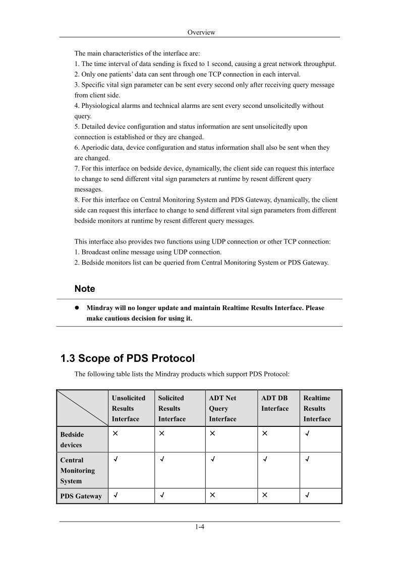
The following table lists the Mindray products which support PDS Protocol:
Unsolicited
Results
Interface
Solicited
Results
Interface
ADT Net
Query
Interface
ADT DB
Interface
Realtime
Results
Interface
Bedside
devices
×××× ×××× ×××× ×××× √√√√
Central
Monitoring
System
√√√√ √√√√ √√√√ √√√√ √√√√
PDS Gateway √√√√ √√√√ ×××× ×××× √√√√

Overview
1-5
‘Bedside devices’ includes the following products: BeneView series of patient monitor, iPM
series of patient monitor or WATO series of anesthesia machine.
Note
� PDS protocols supported by each product have tiny difference. Actual product
should be used for debug and test during the development.
2-1
2 Quick Start
This chapter introduces two interfaces (Unsolicited Results Interface and ADT DB Interface),
other interfaces are the same.
2.1 Unsolicited Results Interface
2.1.1 Step 1. Build the networking
Refer to Chapter 3, run Central Monitoring System or PDS Gateway, setup the IP addresses
of the two network adapters of monitor network and CIS network.
Verify the patient monitors are configured with the IP address of the same sub-net mask with
Central Monitoring System or PDS Gateway.
If a bedside monitor uses the “CMS protocol”, then the network adapter shall be configured
with an IP address 202.114.4.119 and subnet mask 255.255.255.0.
Use “Ping” command to test network connectivity.
2.1.2 Step 2. Connect patient monitors
Refer to chapter 4, discharge the patient and then admit a new one on patient monitor.
Refer to section 5.1, verify the patient monitor is in the tree node “Communication- enabled
Bed”.

Quick Start
2-2
2.1.3 Step 3. Set the IP address to connect CIS
Refer to section 5.2.
2.1.4 Step 4. Set the TCP Listening Port and Data send interval
Refer to section 5.4

Quick Start
2-3
2.1.5 Step 5. Initial connection from CIS
Here using the “Mindray PDS Test Tool (Results Services)” software to simulate CIS to
initial TCP connection.
Select ”Unsolicited Results Interface”,then select ”Enter”.

Quick Start
2-4
2.1.6 Step 6. Check the communication traffic
Refer to section 5.1 to see whether the connection is made.
Refer to section 5.5 to see the HL7 messages.
2.2 ADT DB Interface
2.2.1 Step 1. Build the networking
Refer to section 2.2.1.
2.2.2 Step 2. Run Mindray ADT Server Simulator Software
The “Mindray ADT Server Simulator” is used for demo use or test.
See as below to set the TCP port.

Quick Start
2-5
2.2.3 Step 3. Run Central Monitoring System
Refer to chapter 5, open the Gateway Communication Setup dialog.
1. Refer to section 5.7, select “Database Query”.
2. Refer to section 5.7.3, enter the IP address and TCP Port of the “Mindray ADT Server
Simulator”, then click “apply” button.
3. Refer to section 5.1, check the connection is made or not.
2.2.4 Step 4. Add patient on the simulator
Operate “Admit Patient” on the “Mindray ADT Server Simulator”.
2.2.5 Step 5. View HL7 Message
Refer to section 5.5.
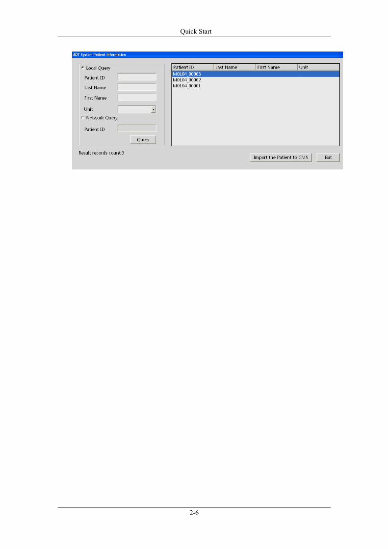
2.2.6 Step 6. Query patient on Central Monitoring System
Select “Query” button on the “Patient Management” page on the Central Monitoring System
to open up the “Query” dialog.
On this dialog, you can see all the patients added on the “Mindray ADT Server Simulator”.
Select one patient, and then select the button “Import the patient to CMS”.
Quick Start
2-6

3-1
3 Networking of the System
There are several modes of networking. Please choose one of them according to the actual
situation.
3.1 Networking with PDS Gateway
Where the Central Monitoring System is not applied (i.e. in Operation Room or Emergency
Room), the PDS Gateway will be used to connect bedside monitors and transfer the result
data to CIS.
Of course CIS can connect directly to the “Realtime Results Interface” on the bedside
monitors (i.e. BeneView series or iPM series), but it is not recommended as the “Realtime
Results Interface” consumes much more network bandwidth and performance of the bedside
monitor.
When connects to the bedside monitors which are not support the “Realtime Results
Interface”, the PDS Gateway should be used.
PDS Gateway can connect the following models of bedside monitor, including but not limited
to: BeneView series, iPM series, PM series, MEC series and VS800. Note, PDS Gateway can
not connect to the WATO series Anesthesia Machine.
Note
� The PDS Gateway and HYPERVISOR VI Central Monitoring System can not
running at a sub-network synchronously.
PDS Gateway shall be installed with two network adapters, one connects internal monitoring
network; the other connects the hospital network. The figure below shows the networking
method.
Networking of the System
3-2
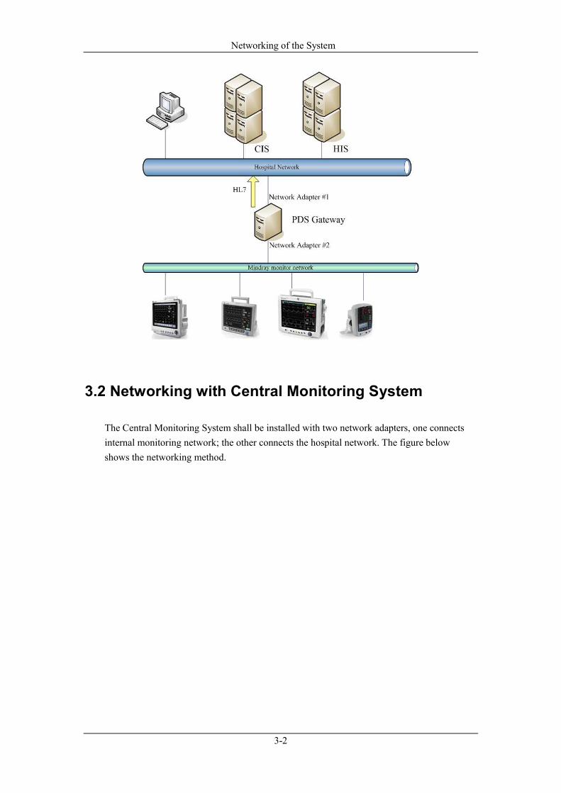
3.2 Networking with Central Monitoring System
The Central Monitoring System shall be installed with two network adapters, one connects
internal monitoring network; the other connects the hospital network. The figure below
shows the networking method.

Networking of the System
3-3
3.3 Networking with bedside device directly
Currently the following bedside devices can support “Realtime Results Interface” to transfer
HL7 message; they are BeneView series patient monitor, iPM series patient monitor and
WATO series Anesthesia Machine.
If the “Unsolicited Results Interface” or “Solicited Results Interface” on the Central
Monitoring System or PDS Gateway can meet the practical application, networking with
bedside device connection directly is not recommended. But the WATO Anesthesia
Machine is an exception, because the Central Monitoring System and PDS Gateway can not
connect to it.
The ‘Results Data Collection System’ of CIS shall be installed with two network adapters,
one connects internal monitoring network; the other connects the hospital network. The
‘Results Data Collection System’ connects directly to the “Realtime Results Interface” on
each bedside device. The figure below shows the networking method.

Networking of the System
3-4
4-1
4 Connection with Mindray bedside monitor
4.1 Network protocol selection
There are two network protocols by which the Central Monitoring System or PDS Gateway
connects to the Mindray bedside monitors. They are “CMS protocol” and “CMS+ protocol”.
The oldest models of beside monitor only support “CMS protocol”, while the newest models
only support “CMS+ protocol”, and the other models can support to select one of them to
use.
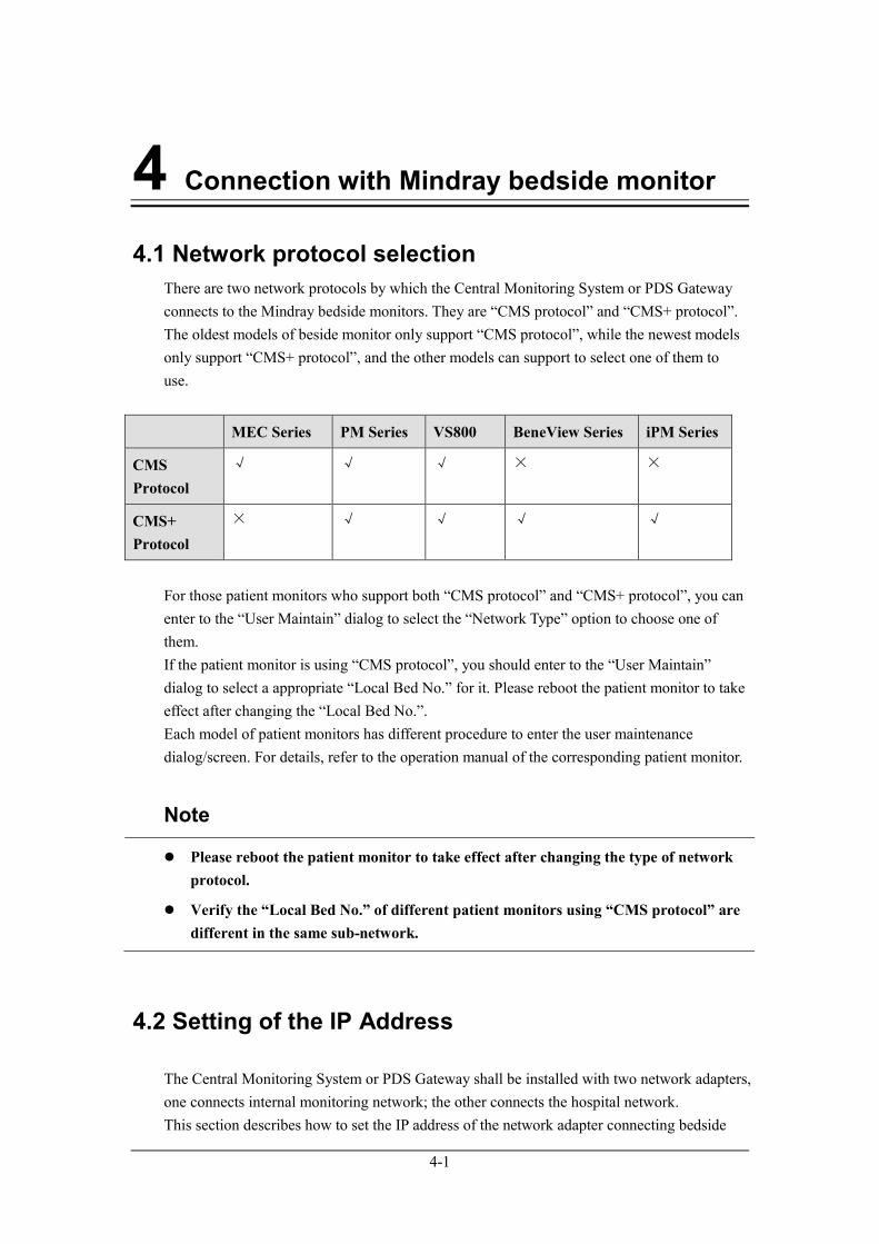
MEC Series PM Series VS800 BeneView Series iPM Series
CMS
Protocol
√ √ √ × ×
CMS+
Protocol
× √ √ √ √
For those patient monitors who support both “CMS protocol” and “CMS+ protocol”, you can
enter to the “User Maintain” dialog to select the “Network Type” option to choose one of
them.
If the patient monitor is using “CMS protocol”, you should enter to the “User Maintain”
dialog to select a appropriate “Local Bed No.” for it. Please reboot the patient monitor to take
effect after changing the “Local Bed No.”.
Each model of patient monitors has different procedure to enter the user maintenance
dialog/screen. For details, refer to the operation manual of the corresponding patient monitor.
Note
� Please reboot the patient monitor to take effect after changing the type of network
protocol.
� Verify the “Local Bed No.” of different patient monitors using “CMS protocol” are
different in the same sub-network.
4.2 Setting of the IP Address
The Central Monitoring System or PDS Gateway shall be installed with two network adapters,
one connects internal monitoring network; the other connects the hospital network.
This section describes how to set the IP address of the network adapter connecting bedside
Connection with Mindray bedside monitor
4-2
monitors.
1. If a bedside monitor uses the “CMS protocol”, then the network adapter shall be
configured with an IP address 202.114.4.119 and subnet mask 255.255.255.0.
2. If a bedside monitor uses the “CMS+ Protocol”, then the network adapter shall be
configured with an IP address which is the same subnet mask of the bedside monitor.
3. If both of the two protocols are used by bedside monitors, then the network adapter shall
be configured with two IP addresses, one shall be 202.114.4.119 with subnet mask
255.255.255.0., the other shall be the same subnet mask of the bedside monitor.
Method to set multiple IP addresses on one network adapter
You can set multiple IP addresses for one network card as instructed below:
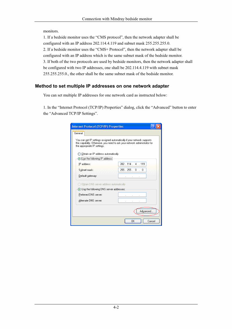
1. In the “Internet Protocol (TCP/IP) Properties” dialog, click the “Advanced” button to enter
the “Advanced TCP/IP Settings”.
Connection with Mindray bedside monitor
4-3
Figure 4-1 Advanced TCP/IP Settings dialog
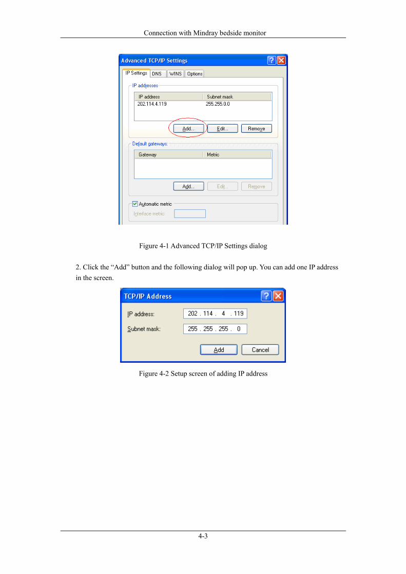
2. Click the “Add” button and the following dialog will pop up. You can add one IP address
in the screen.
Figure 4-2 Setup screen of adding IP address
Connection with Mindray bedside monitor
4-4
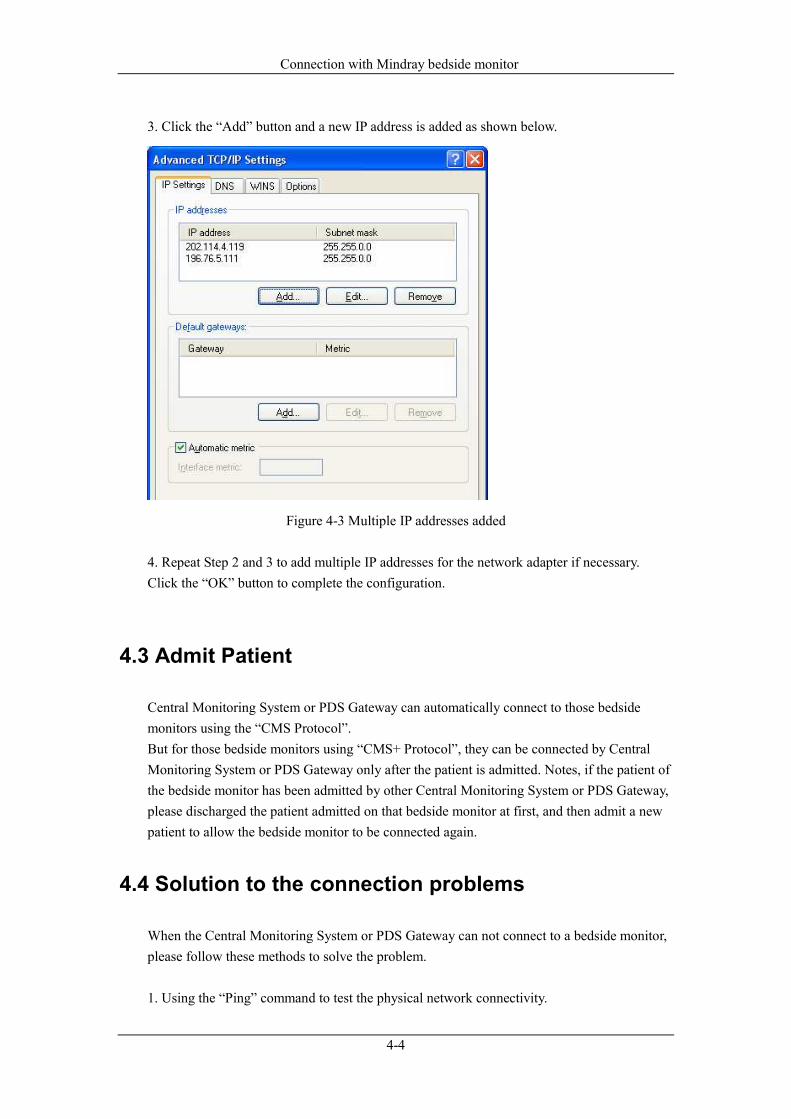
3. Click the “Add” button and a new IP address is added as shown below.
Figure 4-3 Multiple IP addresses added
4. Repeat Step 2 and 3 to add multiple IP addresses for the network adapter if necessary.
Click the “OK” button to complete the configuration.
4.3 Admit Patient
Central Monitoring System or PDS Gateway can automatically connect to those bedside
monitors using the “CMS Protocol”.
But for those bedside monitors using “CMS+ Protocol”, they can be connected by Central
Monitoring System or PDS Gateway only after the patient is admitted. Notes, if the patient of
the bedside monitor has been admitted by other Central Monitoring System or PDS Gateway,
please discharged the patient admitted on that bedside monitor at first, and then admit a new
patient to allow the bedside monitor to be connected again.
4.4 Solution to the connection problems
When the Central Monitoring System or PDS Gateway can not connect to a bedside monitor,
please follow these methods to solve the problem.
1. Using the “Ping” command to test the physical network connectivity.

Connection with Mindray bedside monitor
4-5
2. Verify there is no IP address conflict occurs.
3. Verify the IP address of the Central Monitoring System or PDS Gateway is the same as the
bedside monitor’s subnet.
4. If a bedside monitor uses the “CMS+ Protocol”, please check whether the IP address
202.114.4.119 with subnet mask 255.255.255.0. are configured on the Central Monitoring
System or PDS Gateway.
5. Please discharged the old patient on that bedside monitor at first, and then admit a new
patient to allow the bedside monitor to be connected again.
6. The bedside monitor shall be in the “Monitor List” on the Central Monitoring System, in
order to be allowed for connection.
5-1
5 Settings and management
This Chapter describes the settings and management of four interfaces: Unsolicited Interface,
Solicited Interface, ADT DB Interface and ADT Net Query Interface. There is no setting and
management available for the Realtime Results Interface.
You can open the user interface/screen as follow:
1. Select the buttons in sequence on the Central Monitoring System: “Admin Setup”, “Other”,
and “Gateway Communication Setting”.
2. Click the PDS Gateway small icon on the Windows desktop tray, select the “Main Screen”
item on the popup menu.
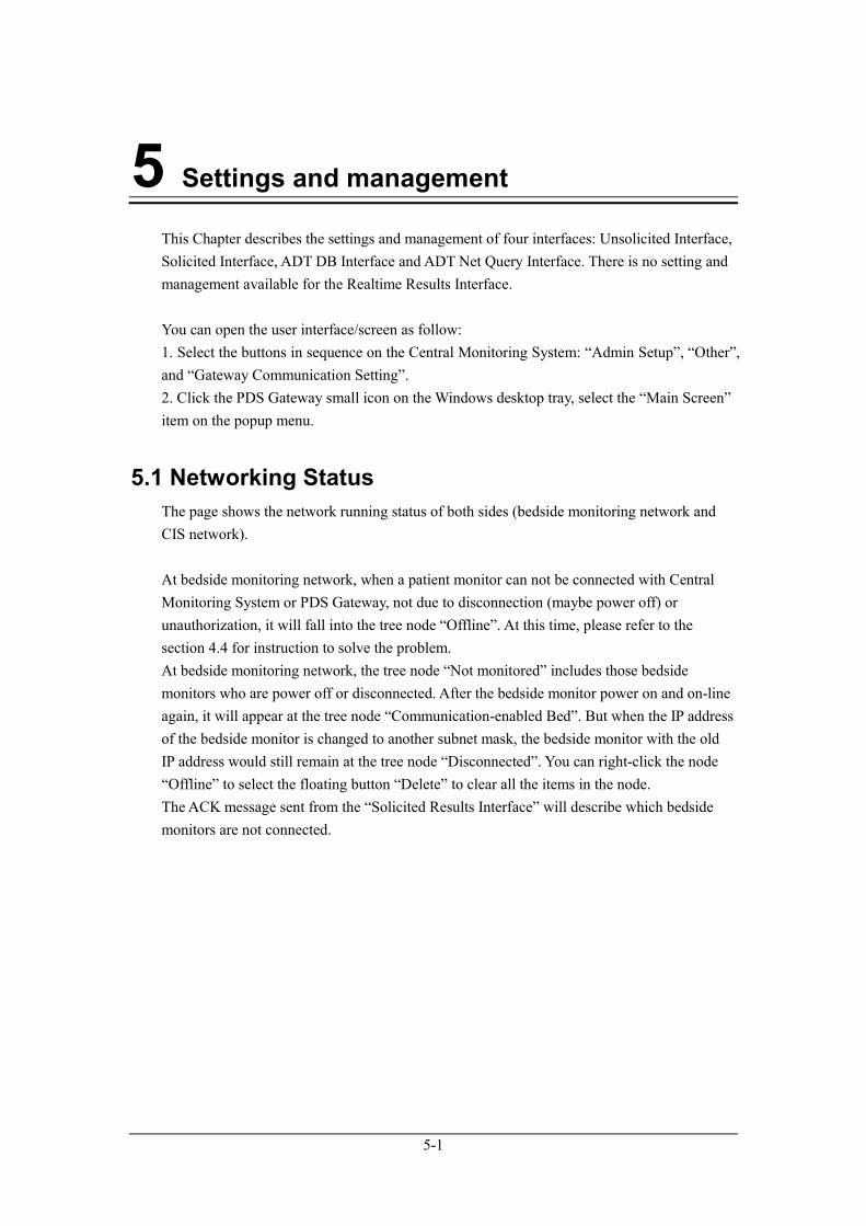
5.1 Networking Status
The page shows the network running status of both sides (bedside monitoring network and
CIS network).
At bedside monitoring network, when a patient monitor can not be connected with Central
Monitoring System or PDS Gateway, not due to disconnection (maybe power off) or
unauthorization, it will fall into the tree node “Offline”. At this time, please refer to the
section 4.4 for instruction to solve the problem.
At bedside monitoring network, the tree node “Not monitored” includes those bedside
monitors who are power off or disconnected. After the bedside monitor power on and on-line
again, it will appear at the tree node “Communication-enabled Bed”. But when the IP address
of the bedside monitor is changed to another subnet mask, the bedside monitor with the old
IP address would still remain at the tree node “Disconnected”. You can right-click the node
“Offline” to select the floating button “Delete” to clear all the items in the node.
The ACK message sent from the “Solicited Results Interface” will describe which bedside
monitors are not connected.
Settings and management
5-2
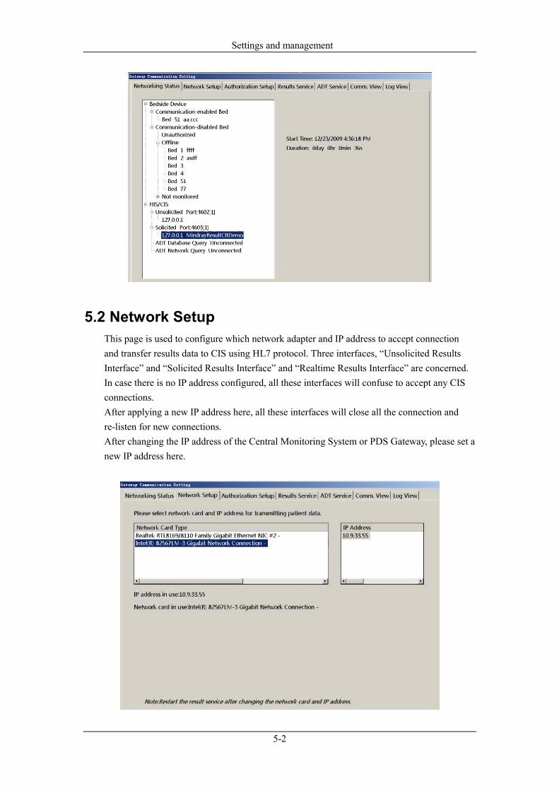
5.2 Network Setup
This page is used to configure which network adapter and IP address to accept connection
and transfer results data to CIS using HL7 protocol. Three interfaces, “Unsolicited Results
Interface” and “Solicited Results Interface” and “Realtime Results Interface” are concerned.
In case there is no IP address configured, all these interfaces will confuse to accept any CIS
connections.
After applying a new IP address here, all these interfaces will close all the connection and
re-listen for new connections.
After changing the IP address of the Central Monitoring System or PDS Gateway, please set a
new IP address here.
Settings and management
5-3
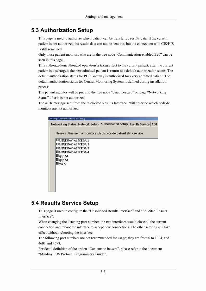
5.3 Authorization Setup
This page is used to authorize which patient can be transferred results data. If the current
patient is not authorized, its results data can not be sent out, but the connection with CIS/HIS
is still remained.
Only those patient monitors who are in the tree node “Communication-enabled Bed” can be
seen in this page.
This authorized/unauthorized operation is taken effect to the current patient, after the current
patient is discharged; the new admitted patient is return to a default authorization status. The
default authorization status for PDS Gateway is authorized for every admitted patient. The
default authorization status for Central Monitoring System is defined during installation
process.
The patient monitor will be put into the tree node “Unauthorized” on page “Networking
Status” after it is not authorized.
The ACK message sent from the “Solicited Results Interface” will describe which bedside
monitors are not authorized.
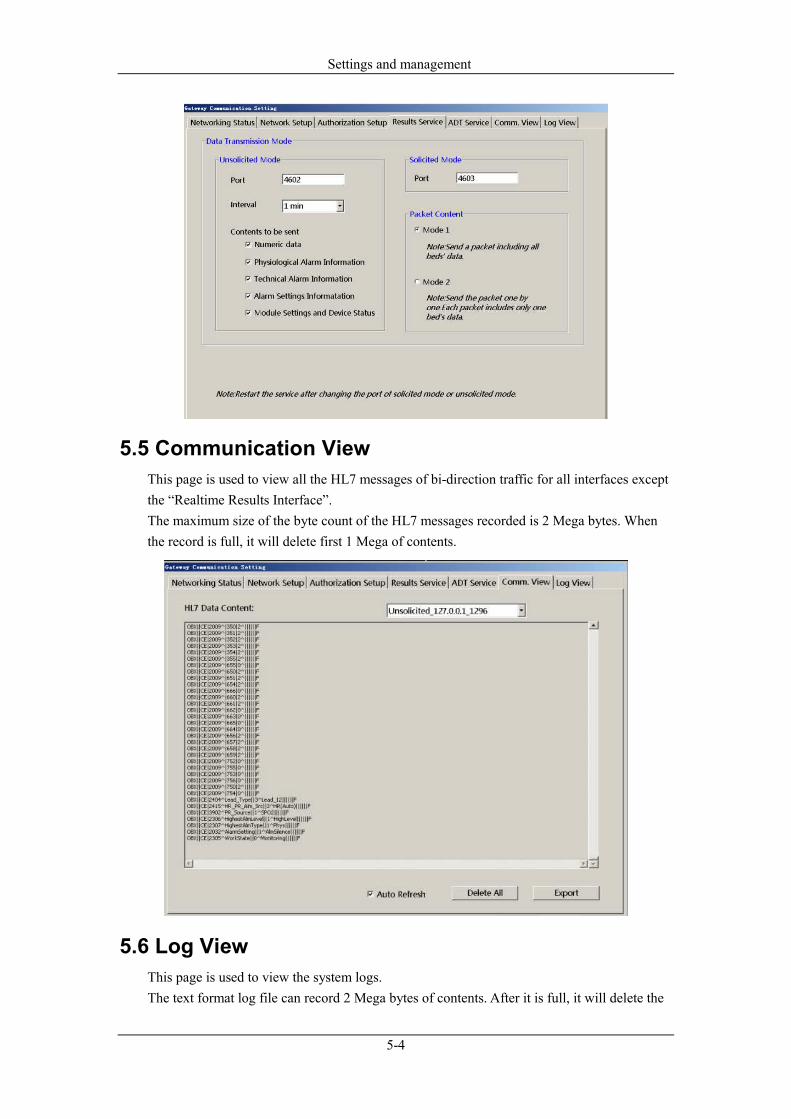
5.4 Results Service Setup
This page is used to configure the “Unsolicited Results Interface” and “Solicited Results
Interface”.
When changing the listening port number, the two interfaces would close all the current
connection and reboot the interface to accept new connections. The other settings will take
effect without rebooting the interface.
The following port numbers are not recommended for usage, they are from 0 to 1024, and
4601 and 4678.
For detail definition of the option “Contents to be sent”, please refer to the document
“Mindray PDS Protocol Programmer's Guide”.
Settings and management
5-4
5.5 Communication View
This page is used to view all the HL7 messages of bi-direction traffic for all interfaces except
the “Realtime Results Interface”.
The maximum size of the byte count of the HL7 messages recorded is 2 Mega bytes. When
the record is full, it will delete first 1 Mega of contents.
5.6 Log View
This page is used to view the system logs.
The text format log file can record 2 Mega bytes of contents. After it is full, it will delete the

Settings and management
5-5
first 1 Mega bytes of contents.
When there is a fault or exception occurs, please view this log first.
The PDS Gateway can export two different logs; one is in text format as seen on this page,
the other is a compressed binary file which is used for Mindray internal analyzing.
On Central Monitoring System, in addition to export textual logs in this page, you can export
the compressed binary file in the View Log page of the system owned. Also, the compressed
binary file is for internal analyzing.
5.7 ADT Services Setup
This page is provided by Central Monitoring System only.

Settings and management
5-6
5.7.1 Patient Info Keywords and Association
“Patient Info Keywords” and “Association” are related. The Central Monitoring System uses
the defined “Patient Info Keywords” to identify uniquely a patient internally.
After selecting “Auto Association” or “Manual Association”, the Central Monitoring System
can copy or update the patient demographic data from the ADT system outside to the local
patient who have the same “Patient Info Keywords”. With “Auto Association”, the Central
Monitoring System can automatically perform the copying operation without intervention,
but will flash a notification on the screen for 30 seconds. With “Manual Association”, the
Central Monitoring System will popup a confirm dialog for user to choose whether apply the
outside patient demographic data or not.
5.7.2 Patient Info Association Content
There are two situations will apply this configuration:
1. When association is made, the Central Monitoring System will copy the selected items to
the local patient.
2. Central Monitoring System provides a dialog to query patient demographics from ADT
system. User can select one from the query results to populate the local, but only the items
selected in this setting will be used.
5.7.3 Connect to the ADT Server
For the two ADT interfaces, Central Monitoring System acts as TCP client to establish the
connection with the server. The IP address and port number of the server can be set in this
page. After the new IP address or port number is applied, Central Monitoring System will
make a new connect immediately.
In case of disconnection, Central Monitoring System will re-connect to the server in 1 min
interval.
6-1
6 Performance Specification
This message is only available in Solicited ADT Interface.
6.1 The max count of the CIS/EMR connection
The “Realtime Results Interface” on Central Monitoring System can accept 16 concurrent
connections; PDS Gateway can accept 64 concurrent connections; Bedside device may accept
1 to 4 concurrent connections, the count is different with different type and model of bedside
device.
The Central Monitoring System or PDS Gateway can accept maximum 4 concurrent
connections for both “Unsolicited Results Interface” and “Solicited Results Interface”.
The Central Monitoring System can make one ADT DB and ADT Net Query connection
simultaneously and independently.
6.2 The max count of the bedside connection
The PDS Gateway can make maximum 64 connections of bedside monitors simultaneously.
The Central Monitoring System can make maximum 32 connections of bedside monitors
simultaneously.
6.3 The ADT Database capacity
The ADT Database capacity is limited to 10,000 patients. When it is full, it will delete the
earliest record following the principle of FIFO.
7-1
7 Installation
7.1 License Key
1. A hardware License Key (dongle) shall be present on the USB port of the PDS Gateway
while the system is running.
2. A hardware License Key (dongle) shall be present on the USB port of the Central
Monitoring System while the system is running. The ADT Interfaces option (combination of
ADT DB Interface and ADT Net Query Interface) will be enabled via the License Key
(dongle). The Results Interfaces option (combination of Unsolicited Results Interface and
Solicited Results Interface) will be enabled via the License Key (dongle).
Warning
� Mindray owns the copyrights to this PDS gateway. Use this software and the
correct license document under the authorization of Mindray. Mindray holds
legal responsibilities to any copy or use of this software without the written
permission of Mindray.
7.2 License for the “Realtime Results Interface”
This interface is enabled always without License Key on the bedside monitors and on the
Central Monitoring System, but it is enabled on the PDS Gateway along with the
“Unsolicited Results Interface” and “Solicited Results Interface” via License Key (dongle).
7.3 Installation of Central Monitoring System
Please refer to the Central Monitoring System Installation Guide.
Installation
7-2
7.4 Installation and use of the PDS Gateway
Warning
� The PDS gateway CD may be contaminated by microorganism during the
storage, transport and use. Check the package for damage before use. If you see
any sign of damage, contact the carrier or Mindray immediately.
7.4.1 Operating system requirements
PDS Gateway can be installed and running on the following operation system:
� Windows 2003 Server Sp2 Chinese/English version
� Windows XP Professional Sp2 Chinese/English version
Note
� The Service Patch 2 shall be installed on the Windows Operation System.
� The background service ‘Windows Firewall/Internet Connection Sharing (ICS)’
will start automatically after the Windows Operation System starts. Please do
not shutdown this service; otherwise the PDS Gateway can not start normally.
� In order that the PDS Gateway can run well and stably, please don’t install any
other irrelevant softwares, except the appropriate anti-virus and safety-related
softwares.
7.4.2 Computer Hardware Minimum Configuration
Make sure the computer can meet the following minimum configuration:
CPU:Dual Core Intel Core 2 E6320, 1866MHz
Physical Memory: 2G
Free space of the hard disk (where the software is installed): 1G
Network adapter: shall install two adapters.
7.4.3 IP Address Setting
Please refer to the section 4.2.

Installation
7-3
7.4.4 Installation notes
1. Before install the software, please set the IP addresses correctly (refer to section 4.2). Two
network adapters shall be installed on the computer.
2. Before install the software, plug in the License Key (dongle).
3. During the installation, when the dialog “Hospital Information” is meet, please select the
IP address which is connected to the CIS. If you want to change this setting, refer to section
5.2.
4. During the installation, when the dialog below is meet, please input the correct content
otherwise they can not be changed after the installation process.
5. Restart the operation system manually when finishing the installation process.
7.4.5 Start
The PDS Gateway can startup automatically after the Windows user is logon and enters the
desktop, as the shortcut of the PDS Gateway executable file has been copied to the folder “C:
\ Documents and Settings \ All Users \ Start menu \ programs \ Startup”.
Note
� PDS Gateway can only startup after the Windows user is logon and Windows
desktop is entered.
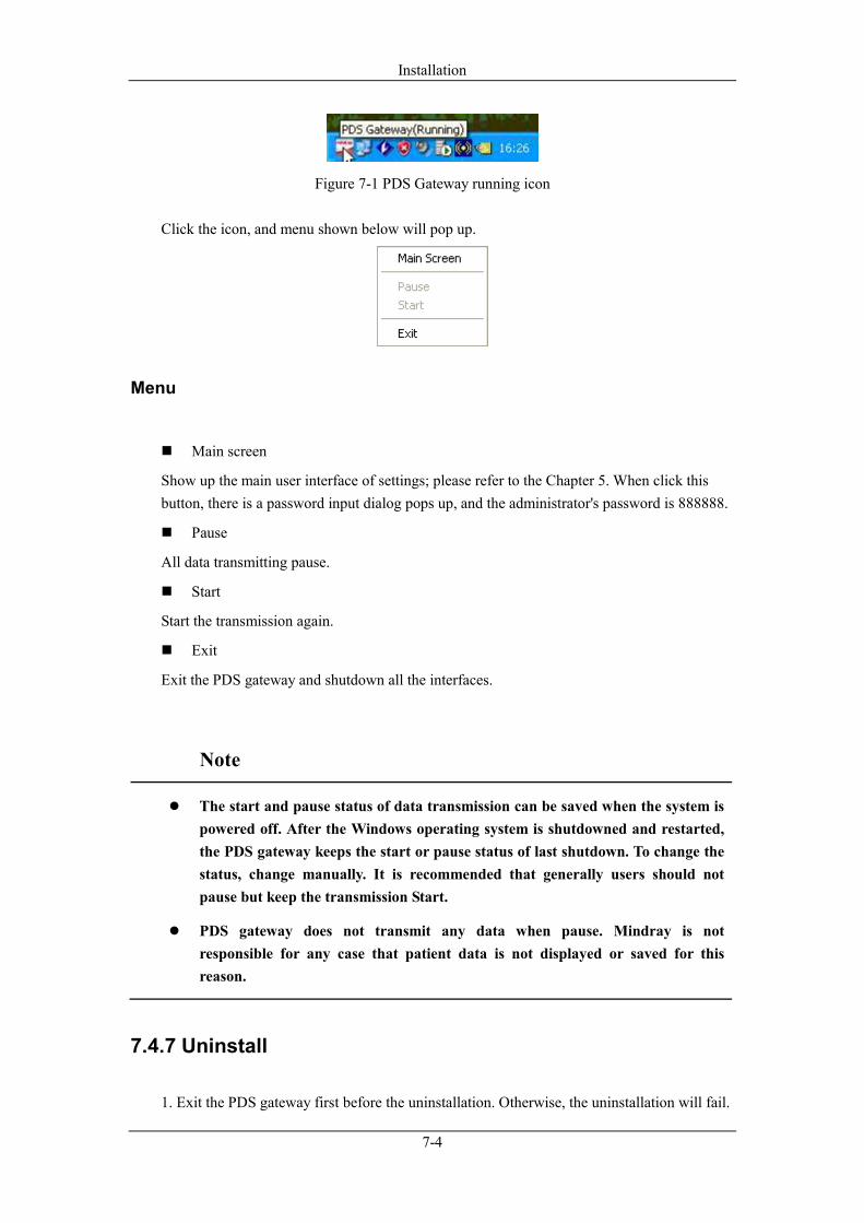
7.4.6 User interface and menu
User interface
After PDS gateway starts, a new icon is added in the lower right corner of Windows desktop
toolbar tray as shown below.
Installation
7-4
Figure 7-1 PDS Gateway running icon
Click the icon, and menu shown below will pop up.
Menu
� Main screen
Show up the main user interface of settings; please refer to the Chapter 5. When click this
button, there is a password input dialog pops up, and the administrator's password is 888888.
� Pause
All data transmitting pause.
� Start
Start the transmission again.
� Exit
Exit the PDS gateway and shutdown all the interfaces.
Note
� The start and pause status of data transmission can be saved when the system is
powered off. After the Windows operating system is shutdowned and restarted,
the PDS gateway keeps the start or pause status of last shutdown. To change the
status, change manually. It is recommended that generally users should not
pause but keep the transmission Start.
� PDS gateway does not transmit any data when pause. Mindray is not
responsible for any case that patient data is not displayed or saved for this
reason.
7.4.7 Uninstall
1. Exit the PDS gateway first before the uninstallation. Otherwise, the uninstallation will fail.

Installation
7-5
2. To uninstall the PDS gateway, enter the “Control Panel-Adding or deleting program”
screen of Windows operating system. Select the “PDS gateway” in the current program list,
click the “Delete” button and then follow the instructions to uninstall the software.

Installation
7-6
Blank Page

P/N: 0010-20-43061-1 (10.0)


