If nothing is done to improve chilled water pipeinsulation systems, over time the arrivingchilled water temperatures in the workingsections of mines will increase from anoperational norm of 10°C to a norm of 13°C.
The reasons for the use of refrigeration inthe hot underground gold mines of SouthAfrica are not disputed. The science oftransferring the required refrigeration intowater for ease of distribution in mines isaccepted practice. However, the techniquesassociated with the transfer of large quantities
of cold fluid down and through deep andextensive underground mines are unique, andtherefore usually require to be designed byspecialists.
The water quantities and water pressuresinvolved are high, and distributing waterquantities in excess of 1 000 kg/s at pressuresof up to 4 000 kPa are fairly common for alarge mine distribution system.
The primary method of water reticulationis via suitably sized and selected steel piping.It is often associated with pressure-reducingvalves, energy recovery systems and largedams.
The temperature range of the water leavingthe refrigeration plants is typically 3 to 5°C,and the arriving temperatures of this water atits final destination is ideally 8 to 10°C,depending on the vertical and horizontaldistance travelled.
The reasons for this temperature increaseare governed by many factors, such as:
➤ Fluid compression with depth (JouleThomson effect, JT) and the non-use ofenergy recovery systems
➤ Friction losses and therefore theselection of fluid flow rate in theconveying pipes
➤ Heat flow from the surrounding rockinto the ambient air due to increasedgeothermal gradient with depth
➤ Type and quality of the Chilled WaterPipe (CWP) insulation system
➤ Size and insulation system of storagedams
➤ Size and maintenance of Chilled WaterPipes
➤ Damage to the vapour brake ofinsulation material.
Mine cooling and insulation of chilledwater transport pipesby C.A. Rawlins*
Synopsis
Deep underground mines use refrigeration systems to provide areasonably comfortable ambient environment to increase produc-tivity and to maintain safety as a priority. Deep level gold minesmaintain the environment at an acceptable temperature, i.e. 27°C.However, the increasing cost of doing so through refrigeration isbecoming a significant factor in the economic viability of mines.
This paper discusses of the important facet of energy losses incooling reticulation systems, laying with the specific emphasis onthe subject of chilled water transport pipe insulation and its thermo-dynamic relationships. Aspects relating to the deterioration of opencell-type insulation materials such as polyurethane/styrene foamsand the use of Phenolic resins that have good fire retardationproperties have been investigated. The thermal conductivities ofthese insulation media are good (meaning below 0.05 W/°C)However, they are known to be negatively influenced by watervapour ingress and vapour pressure differences that result in theingress of water into the material by means of absorption, conden-sation, hygrospicity, permeability and capillary action, to name afew of many.
The overall effect on mine cooling efficiency takes in the twoforms: first by the loss of refrigeration or increased chill in the watertemperature arriving in a given section and second, by a loss intransfer efficiency when the gap between the arriving watertemperature and the actual air temperature decreases.
681The Journal of The Southern African Institute of Mining and Metallurgy VOLUME 107 REFEREED PAPER OCTOBER 2007 ▲
SAIMM_Oct_79-86:Template Journal 11/5/07 8:29 AM Page 681
Mine cooling and insulation of chilled water transport pipes
The increase in temperature of water as it flows along apipe is not only due to the reasons given above but a directloss of the energy that is delivered at the workings (throughenergy transfer systems/units) in the form of air cooling.Obviously, the mine cooling philosophy plays an importantrole. Other factors such as positioning and type of refrig-eration systems (surface only, surface and underground, ice,ammonia, etc.) must be considered and the mode of waterdistribution to and from the working is an important factor.The so-called ‘open’ and ‘close’ circuit reticulation systems(high and low pressure type) systems are used, and thedifferences between these and reasoning for the use of eitherare depends on the system design.
Regardless of the refrigeration or transportation systemsused, an increase in the arriving temperature of the chilledwater at the working place for the cooling of the ventilationair can be considered a direct loss in generated refrigeration.The formula kW(R) = Mw (mass flow-kg/s) x Δt (watertemperature difference-°C) x Cw (specific heat or thermalcapacity of water-J/kg°C) indicates that the greater thetemperature difference (Δt), the more refrigeration is required(kW(R)) for a given mass flow (Mw) of water with a Cw of4,187 kJ/kg°C. In essence, the lower the temperaturedifference (Δt) between two transfer points (intake and pointof application), the lower the amount of refrigeration thatneeds to be generated and, again, the lower the transportmass of the water which in effect then influences the pipesizes etc.
It thus stands to reason that the ‘conservation’ of thedeparture water temperature from a given refrigeration plantis essential in any mine to prevent so-called ‘line losses’,which result in:
a Oversized refrigeration plants b Oversized water transport piping systems (more chilled
water required)c Inflated capital and running costsd Dramatic changes in the cold water to air transfer
efficiencies (cooling coils or bulk air coolers) in theworking places when the gap between the arrivingwater temperature and the actual air temperature isdecreased.
The single largest reason for the increase in CWT (chilledwater temperatures) in a mine after the JT effect is a poorquality CWP insulation system.
This paper reviews the mine application of CWPinsulation and identifies possible reasons for their deterio-rating. It also proposes guidelines for the improvement ofinsulation systems and the upgrading of the general specifi-cation in order to satisfy the future needs of deep mines.
The general problemThe aim of using CWP insulation is to contain the valuableenergy stored with the reticulation system. For many years,the most commonly-used underground pipe insulation mediawas polyurethane (PUR). Because of the fire-related problemsassociated with PUR, in 1989 the gold mines embarked on asystematic removal of polyurethane insulation on chilledwater reticulation piping. The mines were only partially
successful and PUR insulation still exists, although varioustypes of fire protection sleeve are now in use.
The quest for a technically and practically viablealternative also started at this time. This explains thepopularity of the now fairly widely used fire retardantPhenolic foam. (Note that the available generic specification‘Thermal insulation for chilled water piping’ states thatpolyurethane or polystyrene-based materials shall not beused underground.)
The in situ replacement of the stripped PUR insulationwith alternatives such as glass fibre wool and, for thatmatter, half round Phenolic foam insulation sections hasproved to be difficult for many practical and cost-relatedreasons. Consequently, large portions of the older CWPs inthe mines remain either uninsulated or poorly insulated.
The newer sections of the mines generally use pipes thathave been pre-insulated on surface. These pre-insulatedsystems come mainly in two forms:
➤ UPVC (Unplasticised Polyvinyl Chloride) sleeves(maximum thickness 3.0 mm) around metallic pipesthat are injected with Phenolic foam to a requiredthickness and sealed at each end. The vapour barrier inthis case is the UPVC sleeve, the ends of which areusually glued into place. The UPVC also acts as amechanical protection to the foam material
➤ Pre-cut Phenolic foam half rounds that areencapsulated in a laminated aluminium polyethylenecoated foil that acts as the vapour barrier and is kept inplace around the foam half round shape by vacuum.The insulation and vapour barrier in then protected bya galvanised or stainless steel sleeve.
Phenolic or, for that matter PUR foams have very good k-values (low thermal conductivity) properties (k ≈ 0.03W/mK). They are influenced by water vapour ingress due tothe vapour pressure difference that is generated between theactual in-mine atmospheric conditions and the atmosphericconditions at the surface of the CWP.
The ingress of this water vapour into the foam increasesthe k-value of the insulation material and results in vapourcondensing on the outside wall of the insulation when thedew point temperatures are attained. This condensate furtherpenetrates the insulation via physical mechanisms such ashygrospicity, permeability and capillary action. When the k-value of the insulation reaches that of water (k = ± 0.6W/mK), the effect of the dew point now results in conden-sation on the outside of the steel pipe and eventual waterlogging of the entire insulation system around the steel pipe.
To overcome the ingress of water vapour into theinsulation, a suitable water vapour barrier (WVB) is wrappedaround the insulation material.
The partial pressure difference between the outside of theinsulation and the inside of the insulation (pipe interface)can be as high as 4 000 Pa and, with this driving force, thequality of the WVB must be of the highest standard. Underthe driving force of the partial pressure difference, the flow ofwater vapour will depend on the behaviour of the WVB. If itis totally vapour-tight material such as metal or glass, thevapour ingress will be zero or insignificant. If it is not fitted
▲
682 OCTOBER 2007 VOLUME 107 REFEREED PAPER The Journal of The Southern African Institute of Mining and Metallurgy
SAIMM_Oct_79-86:Template Journal 11/5/07 8:29 AM Page 682
tightly (with the vacuum placed within) and maintainedundamaged on the insulating material, the vapour ingresswill be significant.
The flow of 1 gram of water through a material of giventhickness per square metre of surface area per 24 hours istermed permeance. This is a performance value and not aproperty of the material. (The generic thermal insulationspecification previously referred to calls for 0.2 g/m²/24 hrs.).
The water vapour diffusion resistance number (μ) is theratio of the resistance of a layer of material (to water vapourdiffusion) to the resistance of a layer of air of the samethickness, under the same conditions of temperature andatmospheric pressure. It expresses how many times better thematerial resists water vapour passage than air does. As amatter of appreciation, an insulation material will require a μvalue of at least several thousand to be satisfactory for mostapplications, so special means should be used to protect itfrom moisture penetration and transfer. Phenolic foam haslimited resistance with a μ value of 30 to 50. Phenolic foammust, therefore, be protected with a WVB with a μ value of 20 000 to 50 000 such as a thick bitumen, aluminium,polyethylene foil with a thickness of 0.1 mm or a solid steelpipe.
A typical WVB in use on Phenolic insulation material is152 micro meter thick composite polyethylene (63,5 μ)/aluminium (25 μ)/polyethylene (63,5 μ) [3 layer] foil. Onlythis product meets the current specification for water vapourtransmission of 0.2 g/m²/24hours (SABS tested (ASTM E96)WVB = 0.17 g/m²/24h). UPVC piping with a 3.2 mm thickwall has water vapour transmission rates of ± 2 to 3 g/m²/24hours!
The puncture resistance of UPVC is good, while thepuncture resistance of aluminium polyethylene foil is poor.Portions of the modern Phenolic type insulation in somemines are contaminated with water vapour.
Another important factor affecting the loss of cooling ortemperature rise in transported CW is the practice of notinsulating the CWP flanges.
The following example is given to illustrate temperaturerise over a flange section:
CWP length: 9.1 mPipe section insulated: 8.8 mUninsulated section: 0.3 mPipe size: 250 mm ∅Insulation material thickness: 40 mmTemperature change over insulated section: 0.0713°CTemperature change over un-insul. section: 0.0709°CIt can be seen that the temperature rise over the 450 mm
un-insulated flange is virtually identical to the temperaturerise over the entire 8.8 m of insulated pipe.
The basic cause of unacceptably high arriving chilledwater temperatures in the underground workings of minescan be categorized as follows:
Design
➤ No insulation has been placed on CWPs. (The reasonoften given is that the cooling losses are transferredinto the air, whereas in actual fact the losses manifestas condensate on the steel pipes that falls into the drainand imparts minimal cooling to the actual air)
➤ Sizing of CWPs in relation to flow rates is incorrect,which results in temperature rises, especially in non-insulated or poorly-insulated pipes when low flow ratesare experienced.
Engineering
➤ The loss or breaching of the vapour barrier oninsulated pipes results in an increase in K-value of thePhenolic or PUR insulation
➤ The non-insulation or poor insulation of CWP flanges➤ The poor maintenance of damaged insulation on CWPs.
Management
➤ The general lack of understanding of the requirementsof a good insulation system
➤ The neglect or limited use of the insulation techniqueson chilled water storage dams
➤ The non-compliance of purchased insulation systemswith company specifications.
The compounding effect of all of these factors hasresulted in arriving water temperatures at the workings of 12to 16°C when they should be in the order of to 8 to 10°C.
Basic solutions
The ever-increasing pressure on the gold mines to produce atlower cost has resulted in the review of every component ofan underground refrigeration system. The increasing capitaland running costs of these large cooling installations andwater reticulation systems and the requirement to mine moredeeply have made an appraisal of the operating efficiencies ofthe present and future cooling systems necessary.
The solutions suggested are based on the following set offundamentals:
➤ Upgrading the general knowledge of engineers andenvironmental safety and health managers who areinvolved in the design and selection of piping andinsulation materials.
➤ Providing supply managers with technical tools thatcan be introduced in the form of specially designedsoftware that will allow:a The simulation of conditions that insulation
materials and vapour barriers will operate under,thereby predicting the water vapour transmissionrates needed for compliance with the requiredspecification. The programme also allow theprediction of the life span of a given insulation andWVB under specific water vapour transmissionrates, so that systems to be selected in accordancewith the expected life of mine
b Simulation of the underground environmentalconditions in which a chilled water system isoperating. This allows the prediction of the arrivingwater temperature at any specific length whenvarious types or thickness of insulation areconsidered on a specific pipe type, pipe size and atvarious water temperature and fluid flow rates. Italso considers, the JT effect, pressure reducingvalve, energy recovery and water drainage systems
Mine cooling and insulation of chilled water transport pipesTransaction
Paper
683The Journal of The Southern African Institute of Mining and Metallurgy VOLUME 107 REFEREED PAPER OCTOBER 2007 ▲
SAIMM_Oct_79-86:Template Journal 11/5/07 8:29 AM Page 683
Mine cooling and insulation of chilled water transport pipes
c The prediction of the specific life span (owningcost) scenario, with required input parameters suchas power, capital, interest rates and life of projectby means of a financial model .
➤ Developing general guidelines that will cover selection,installation, fabrication and maintenance of CWPinstallation.
➤ Adopting an updated set of specifications covering thetechnical facets of a total insulation system with anemphasis on improved WVB strength and
➤ Compiling a basic list of currently available productsthat can be used and that comply with the genericspecifications.
Financial implications
The savings that can be derived from improving the quality of the total insulation system of a given mine can best bedemonstrated by an example.
The prevention of 1°C temperature rise in 1 litre of waterin an underground chilled water reticulation system is equalto:
Duty = Mw x Δt x Cw kW(R)= 1 x 1 x 4,187 = 4.187 kW(R)/l/s
The electrical input power to generate 4,187 kW(R) is ±0.963 kW(E) (± 23% per kWR). The present value (PV) ofthis power cost over 20 years at 10% is 8.5, giving the PV ofrunning costs of (0.963 x 8.5 x R 1,600) i.e. R 13,118/°C/l/s(present day electrical power costs are ± R 1,600/kW/-annum).
The capital cost of a total refrigeration plant and reticu-lation system is estimated at R 8500/kWR and thusconstitutes a one-off payment of ≈R35,600/°C/l/s (8500 x4.187).
The total owning cost of a l/s of water transported with aloss/gain of 1°C over a typical refrigeration system is, thus,≈R 49,000.
On a mine reticulating, say, 1,000 L/s of chilled water,the cost implication would be a (1,000 x R 49,000 = R 50million), saving or loss of ≈R 50 million over a project periodof 20 years.
An improvement in arriving water temperature of 1°C iseasily attainable if good total insulation systems are used,but improvements of at least 2°C and more should be aimedfor. With the present estimated cost of insulation at around5% of the capital cost of a refrigeration system, the justifi-cation for good and maintained insulation is self-evident.
Causes of refrigeration losses in chilled water reticulation systems
Basic reasons
The more descriptive reasons for poor performance of chilledwater reticulation systems are categorized as follows:
Pipe size selections
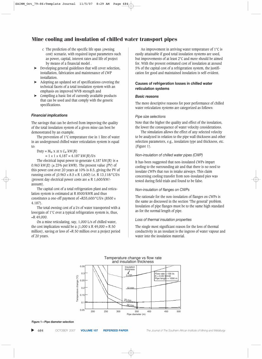
Note that the higher the quality and effect of the insulation,the lower the consequence of water velocity considerations.
The simulation allows the effect of any selected velocityto be analyzed in relation to the pipe wall thickness and otherselection parameters, e.g., insulation type and thickness, etc.(Figure 1).
Non-insulation of chilled water pipes (CWP)
It has been suggested that non-insulated CWPs impartcooling to the surrounding air and that there is no need toinsulate CWPs that run in intake airways. This claimconcerning cooling transfer from non-insulated pies wastested during field trials and found to be false.
Non-insulation of flanges on CWPs
The rationale for the non-insulation of flanges on CWPs isthe same as discussed in the section ‘The general’ problem.Insulation of pipe flanges must be to the same high standardas for the normal length of pipe.
Loss of thermal insulation properties
The single most significant reason for the loss of thermalconductivity in an insulant is the ingress of water vapour andwater into the insulation material.
▲
684 OCTOBER 2007 VOLUME 107 REFEREED PAPER The Journal of The Southern African Institute of Mining and Metallurgy
Figure 1—Pipe diameter selection
Tem
pera
ture
cha
nge
(°C
)
200 250 300 350 400 450 500Pipe diameter (m)
Insulationthickness
Temperature change vs flow rate and insulation thickness
SAIMM_Oct_79-86:Template Journal 11/5/07 8:29 AM Page 684
The water vapour transmission flow through a typicalinsulation material such as PUR or Phenolic is ± 83 g/m²/24hours (tested) under normal underground conditions. Thistransmission is some 415 times greater than the standardWVB requirement of 0.2 g/m²/24 hours. Under theseconditions the k-values of the insulation increase rapidly andwithin days, the insulation will contain ± 40% vapour andthe insulation material’s k-value will increase from 0.05W/mK to 0.25 W/mK.
With time and depending on the dew point temperature,the water vapour starts to condense on the outside of theCWP, and water starts to accumulate between the insulationand the pipe. In time, the insulation starts to absorb thewater to a point where the insulation becomes waterloggedand the overall k-value of the system increases to that of stillwater at ± 0.6 W/mK.
Tests conducted underground on 300 mm ∅ by 2 000 mlong CWP that was insulated with a Phenolic foam productand encapsulated in a foil-type WVB and protectedoccasionally by a spiral wound galvanised iron and UPVChalf section sleeves, revealed that some insulation section k-values were indeed as high as 0.23 W/mK where the WVBwas damaged. Where the WVB was intact and not damaged,the k-value of the insulation was measured at ± 0.05 W/mK.When the k-value ‘equivalent’ of the entire length of the pipesystem is calculated, the average figure of ± 0.5 W/mK isobtained. This increased k-value is attributed to the poorinsulation systems at flanges and the degree of insulationdamage along the pipe systems.
The lack of, or poor maintenance of, water vapour barriers
The water vapour resistance or μ value of normal foam-typeinsulation is low (30–50). (Cellular glass is an exception andhas a μ value of +50 000 which is comparable to the μ valueof a good WVB such as aluminium polyethylene coated foil,as previously indicated.).
In order to protect these foam-type forms of insulationsuch as Phenolic against water vapour ingress, they areusually wrapped or encapsulated in a WVB which has an μ ofvalue at least ≥ 50 000.
A WVB with such a high μ value and a thickness of only≥ 0.1 mm (resistance to water vapour ingress) will allow aminimal water vapour flow rate of ± 0.2 g/m²/24 hours. Inthis way, the insulation is protected because with this lowwater vapour flow rate, the insulation will absorbmoisture/water very slowly. This slow absorption of watergradually alters the k-value of the insulation until iteventually reaches ± 0.25 W/mK. This process can take up to20 years, as confirmed by the simulation model generated. Itis the most likely reason why 0.2 g/m²/24 hours was chosenas a flow rate, 20 years being the average life span of mostprojects.
When the insulation reaches its maximum water loadingcapacity and the k-value has degraded to, say, 0.25 W/mK,occurs condensation, on the outside of the WVB and furtherincreases the energy losses from the CWP system.
From the above rationale, it is fairly obvious that asection of pipe that is well-insulated has its WVB intactshould suffer minimal cooling loss for a long period.However, when the WVB is broken or breached by even thesmallest pin-hole, the resistance to water vapour flow almostinstantly decreases from a μ of 50 000 to 50. The watervapour flow rate increases 400-fold from 0.2 g/m²/24 hoursto ± 80 g/m²/24 hours. Within a short time, the k-value risesfrom ± 0.05 W/mK to 0.25 W/mK and the amount ofcondensate on the outside of the insulation increases becauseof the lower temperature at this point.
Not only does this condensate manifest in loss of coolingbut the condensate flows under the WVB and often fills theWVB bag with water. This ‘soggy bag’ condition exacerbatesthe deterioration of the foam insulation material, increasingthe amount of water it can hold and, further raising its k-value until it reaches that of stil water at ± 0.6 W/mK. (Howlong this takes is unknown, but one must assume thatbecause of the often low pH values associated with thecondensate coming in contact with the insulation material,the deterioration of the foam takes between one and threeyears. Examples of the deteriorated insulation were noted atthe mines during tests conducted.
Because there is a linear relationship between theresistance value Φ and the thickness of a WVB, the thicknessof a UPVC sleeve would have to be at least 12 mm to limit thewater vapour flow rate to 0.2 g/m²/24h.
Water vapour barrier protection
The protection of a WVB is usually accomplished with ametallic sleeve.Alternatively, the WVB may be protected byits thickness and inherent strength, as in the case with UPVC.Where metallic protection is used, the majority of installations are the Galvanised Iron type that is spirallywound, using a joint locking technique to form the pipe. Thistype of protection sleeve, when used with a WVB such asaluminium-coated polyethylene, is a major cause for concern,because when applied over the pipe, it causes minute ‘rips’ inthe WVB material, which damage the WVB before installation.
General insulation assembly problems
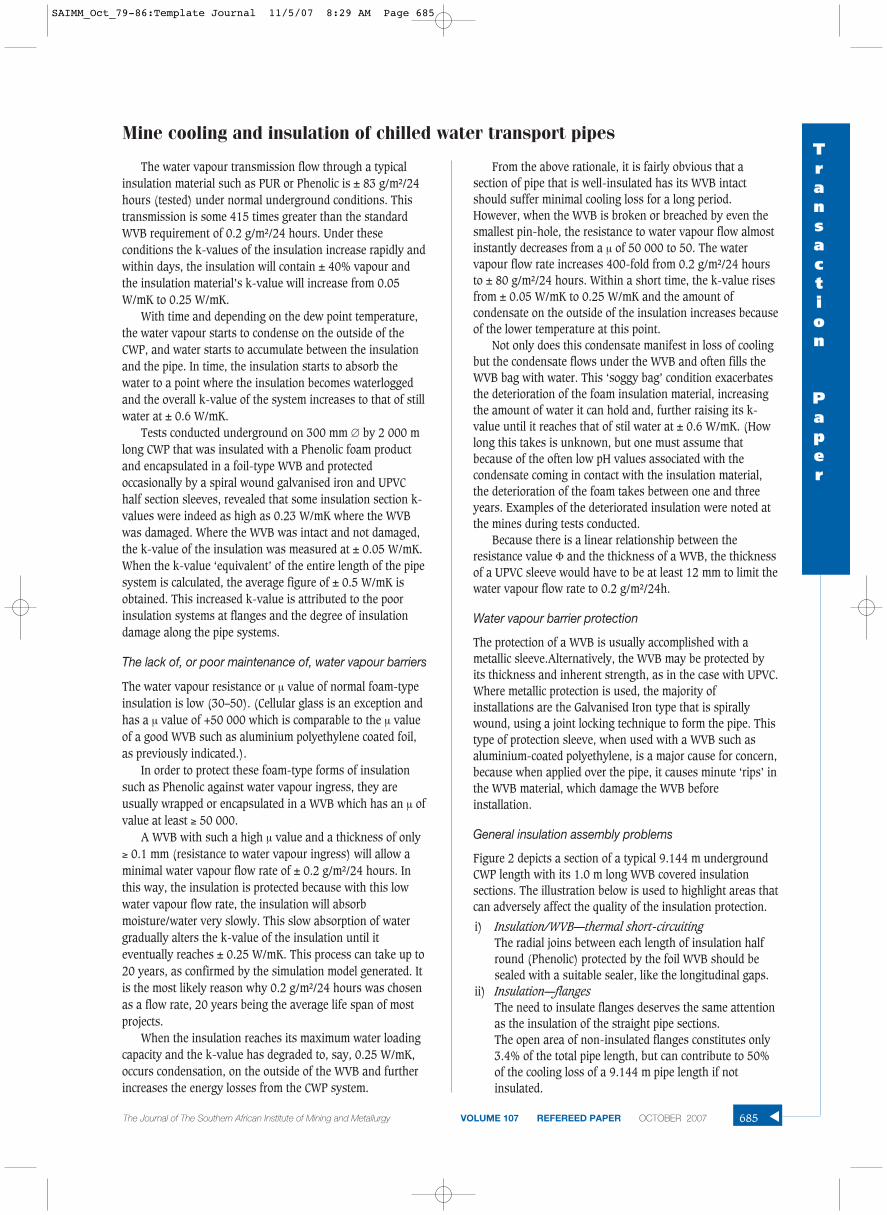
Figure 2 depicts a section of a typical 9.144 m undergroundCWP length with its 1.0 m long WVB covered insulationsections. The illustration below is used to highlight areas thatcan adversely affect the quality of the insulation protection.
i) Insulation/WVB—thermal short-circuitingThe radial joins between each length of insulation halfround (Phenolic) protected by the foil WVB should besealed with a suitable sealer, like the longitudinal gaps.
ii) Insulation—flangesThe need to insulate flanges deserves the same attentionas the insulation of the straight pipe sections.The open area of non-insulated flanges constitutes only3.4% of the total pipe length, but can contribute to 50%of the cooling loss of a 9.144 m pipe length if notinsulated.
Mine cooling and insulation of chilled water transport pipesTransaction
Paper
The Journal of The Southern African Institute of Mining and Metallurgy VOLUME 107 REFEREED PAPER OCTOBER 2007 685 ▲
SAIMM_Oct_79-86:Template Journal 11/5/07 8:29 AM Page 685
Mine cooling and insulation of chilled water transport pipes
Installation of insulated CWPs
There is no getting away from the space constraintsassociated with underground mine shafts and haulages. Theinstallation of insulated CWPs will always be competing forspace with other service installations such as those carryingcompressed air, service water, electricity, etc. Therefore,adequate spacing should be designed for the type of instal-lations required.
General problems
i) Damage during transportation of insulationTransporting the insulation systems from the factory orfrom the fabrication facilities at a mine can cause damageto the highly important WVB. The identification of adamaged foil type WVB is easy and manifests as a‘ballooning effect’ around the Phenolic half roundsections as a result of a loss of vacuum. The transportation problems from the store or fabricationyard to the shaft bank and then down the mine can betermed in-house problems and are numerous. Solutionsrequire complex engineering responses.
ii) Wear and tearApart from the natural ageing of the WVB and insulationsystems, the only other detrimental activity that canaffect CWP insulation systems in situ is physical damagecaused by collision with the pipe and vibration. Collisionsare a safety aspect and the causes are usually wellknown.
iii) Planning and pipe size selectionThe consequence of incorrect pipe size selection inrelation to the water flow rates through a given pipesystem can, over the life of the system, cause arrivingwater temperatures to a section to rise above desirablelevels.The in situ insulation of CWP flanges, valves, etc must becarried out before cold water is allowed to flow throughpipes. The secret to good in situ insulation is ‘keep thepipe dry’.The Design of pipe sizes should take into account theperiod of use, i.e. the peak demand life time required, theflow rate requirement and then the reduced requirementas production decreases (Two smaller pipes might do aspecific job better than one large pipe).
iv) Training and educationAll personnel involved in the selection, purchase, qualityassurance, fabrication, transport installation andmaintenance of underground insulation systems need tobe trained in the requirements of a CWP system.
v) Quality assuranceThe technical specifications for the purchase of insulationand WVB materials must be sound to ensure that theseitems are of sufficiently high quality.
Findings, conclusions and recommendations
General findings
The impact of the systematic removal of polyurethaneinsulation from the chilled water piping (to reduce firehazard) has been minimal. Environmental engineers confirmthat there has been no significant change in wet bulb temper-atures after this extensive stripping exercise. That thearriving temperatures did not drop, as expected, clearlyindicate that the insulation applied at the time had alreadydeteriorated significantly. There is general acceptance ofhigher arriving water temperatures of ± 12°C, in the workingshas been brought about by the introduction of the chilledservice water concept. The use of high-pressure water toremove blasted rock from the face has dramatically increasedthe service water quantities in use on some mines, hasfurther entrenched the workers’ reluctance to accept very coldwater for operational use.
The significant findings arrived at are as follows:
a) The historic and current failure to appreciate thetechnical importance of a WVB has allowed inferiorproducts to be used in the mines. When a WVB isdamaged, for whatever reason, the detrimental effect onthe insulation itself is not fully understood, and thus themotivation for corrective action has been lacking.
b) The fact that water vapour can easily penetrate mostinsulation materials owing to the very high driving forcegenerated by the partial vapour pressure differencesacross these insulation systems is not fully appreciated.The concept of a closed cell structure of insulationmaterial can be confusing. It is often assumed thatinsulation is impervious to both water and water vapour.Both Phenolic and isocyanurate based cellular plastics,although they have closed cell structures, easily ‘breathe’
▲
686 OCTOBER 2007 VOLUME 107 REFEREED PAPER The Journal of The Southern African Institute of Mining and Metallurgy
Figure 2—Typical pipe including insulation and sleeve
POP RIVERTED TO SPIRAL PROTECTION SLEEVE STEEL STOPPER
STEEL PIPE GAP INSERTED END CAPS FLANGESPIRAL WOUND MECHANICALPROTECTION SLEEVE
INSULATION ANDVAPOUR BARRER
SAIMM_Oct_79-86:Template Journal 11/5/07 8:29 AM Page 686
and thus transmit moisture vapour in the same manneras wood and naturally-occurring cellular products.As mentioned, the partial pressure difference calculatedis between 3 kPa and 4 kPa across an insulation system.This can easily force water vapour into the cell structure,where it is quickly condensed into water, which dilutesand replaces the fluorocarbon gases that provide the lowk-values associated with these materials. Theconsequence is a increase in k-value that raises theresistance within the insulation. This in turn promotesfurther condensation and loss of cooling owing toincreased latent heat transfer.
c) The important need to seal or bond together thelongitudinal, radial and end piece joints of WVBs inencapsulated insulation half-rounds is not recognised oracted on. These half rounds are held together by tapebound around the system at certain intervals, and thencovered by a protective sleeve. Water vapour ingress viathese many unsealed gaps can easily occur, and explainswhy condensate drips out at the ends of these pipesystems. When flanges are insulated, bonding or sealingof the joints is seldom undertaken. That omission almostnullifies the benefits obtained from flange insulation.Note that the bonding or sealing compounds must havethe same water vapour transmission characteristics asthe WVB itself (0.2 g/m²/24 hrs and a µ value of at least50 000).
d) The quality of underground insulation systems outsidethe general refrigeration plant areas is poor. The non-insulation of flanges coupled with the poor maintenanceof damaged sections add to the low overall efficiency ofthe chilled water reticulation systems.
e) The effectiveness of mine air cooling devices such asstope cooling cars (fin and tube), in-stope coolers and,for that matter, direct water to air coolers are alldependent on temperature differentials of ± 20ºC wet-bulb air in—water temperature inlet. This means thatwith typical air inlet temperatures of 29°C wet-bulb tothe cooling coils, the inlet water temperatures to thesecooling systems should be between 8 and 10ºC. For eachdegree of increase in water inlet temperature, theefficiency of the cooling device decreases by 5% and theduties by ± 10%. These decreased efficiencies arecalculated for clean fins and tubes on the cooling coils.The loss of efficiency can be even higher when fins andtubes are fouled.
f) The compounding consequence of all of these detrimentalfactors is the ever-increasing refrigeration capacities thatare installed to overcome these so-called ‘line losses’.The technology to produce more cost-effective refrig-eration such as ice making, and the overcoming of the JTeffect by the use of energy recovery turbines and three-chamber pipe-feeder systems has been vigorouslypursued. However, the development of technology toconserve the cooling produced has fallen behind. Withincreased mining depths the heat loads in the mines willobviously increase, and refrigeration needs will have tobe fully optimized. Part of this optimization will bereduction of temperature increases in chilled water alongsupply pipes to the workings.
Financial implications of these findings
a) The descriptive simulation indicated some of the requiredinformation needed to construct a water temperaturechange model and an owning cost model for a giventypical underground section.
b) The model (not fully detailed here) represented anunderground situation where chilled water is delivered toa level from a chilled water storage dam. The stationarriving water temperatures are shown as covering atemperature range of 6.15°C–7.15°C–8.00°C. On passingthrough a pressure-reducing valve they increase to8.02°C–9.01°C and 10.01°C respectively.
c) The nominal pipe sizes selected are in accordance withthe quantities of water required in the section to satisfycooling needs and calculated arriving water temperature.The optimum flow rates through the selected pipes aredictated by the overall assumed insulation k-values overthe length of the pipe system, and the actual insulationthickness. An example of such an optimisation process isa 300 mm diameter pipe 1,000 m length with anoptimum velocity of 2.15 m/s and insulation materialthickness of 25 mm when the system has an overall k-value of 0.25 W/mK.
d) The total savings indicated that it is financially beneficialto opt for a good overall k-value with due regard for theoptimal insulation thickness. The annual cost savingsper metre of insulated CWP are not provided here.However, calculations indicate that the annual cost permetre saving brought about by good insulation (0.05W/mK) is 2.5 times the cost of the original insulation ataround R 200/m (25 mm thickness). This relates toabout a five-month payback period. In the case of poorinsulation (0.25 W/mK plus uninsulated flanges) thepayback is more than one year.
These costs indicate that even poor insulation is highlybeneficial when compared to no insulation but also highlightsthe massive saving between poor and good insulationsystems. Over 20 years a saving of R 6.1 million for one levelalone; for four main intake levels the saving is ± R 50 million(applicable to this case only).
Conclusions
Technical specification
There are major economic benefits to be derived from theinsulation of chilled water piping (including return waterpipes) and strict compliance with the insulation standardscurrently in place.
The need to insulate all pipe flanges to ensure the long-term integrity of the WVBs around insulation is seen as thesingle most important technical hurdle that must be overcomein an underground mining environment.
Other alternatives can be considered, such as encapsu-lating the insulation in a WVB that is stronger, such as steel(the pipe within a pipe concept). If UPVC is to be consideredas a WVB, it must be sufficiently thick to contain watervapour transmission, and pre-made insulation half roundsmust be inserted inside the gap between the steel pipe andthe UPVC WVB/protection sleeve.
Mine cooling and insulation of chilled water transport pipesTransaction
Paper
The Journal of The Southern African Institute of Mining and Metallurgy VOLUME 107 REFEREED PAPER OCTOBER 2007 687 ▲
SAIMM_Oct_79-86:Template Journal 11/5/07 8:29 AM Page 687
Mine cooling and insulation of chilled water transport pipes
Planning, measurement and managementThere is a need to plan refrigeration requirements on thebasis of the lowest arriving chilled water temperaturespossible in order to minimise the amount of chilled watercirculated and, thus, the size and cost of refrigeration plantand infrastructure. This explains the long-term aim to convey‘ice’ right up to the workings. In the interim, the loss ofcooling due to poor chilled water reticulation practices (suchas lack of correct pipe size selection, poor or non-insulationof pipes, non-insulation of flanges, loss of conductivityvalues of insulation, loss of WVB protection, etc.) must becurtailed.
Recommendations
a) The financial evidence clearly shows that designing andoperating refrigeration systems that cater for line lossesor inefficiencies of more than 40% (mainly because ofpractical or technical constraints) can no longer betolerated. Should this practice continue, the futurecapacity of refrigeration systems will place huge financialburdens on the mines, as mines become deeper and heatloads increase.
b) The use of insulation materials that have low µ values(high water vapour transmission rates) should beconsidered only where the WVB is strong enough towithstand the rigours of the harsh undergroundconditions over a given period. The need to protect boththe insulation and the WVB must be considered. (Thepipe within a pipe concept has much merit).
c) Planning for long-term chilled water insulation needsshould be based on materials that are themselves WVBs,i.e. have high µ values. These materials would thenrequire sleeves only for physical protection and not formpart of a WVB protection requirement.
d) Materials that do not burn independent of their fire-retardant properties) should be given preference. Theseproducts eliminate the need for fire breaks and specialprecautions during transport, storage and installation.
e) All CWPs including their flanges and valves, etc. must beinsulated. The philosophy should be to tolerate onlylosses of up to 10% and less.
f) The need to bond/seal all insulation joints and criticalpipe/steel contact areas must be incorporated into theoverall chilled water insulation system. Its importance,
though immense often ignored is in mine insulationsystems.
g) Only insulation and WVBs that comply with a minesspecification, i.e. ‘thermal insulation system for CWP’should be considered.
h) The size, complexity and financial ramifications of theinsulation problem in the mines require a commensu-rately well-qualified planning, design and controlinfrastructure.
i) The underground in situ insulation methodology shouldbe used only for new refrigeration plant installations,pipe joints and repair/maintenance work. All run-of-minepipes used for chilled water reticulation (shafts andhorizontal) should be insulated on the surface. Thetemptation to undertake in situ re-insulation of oldpiping on levels that are almost worked out should beresisted. The payback would not normally justify theexpense, and the quality of the insulation cannot beguaranteed. It is preferable to concentrate on the newpipe installations and demand the highest quality.
j) The typical underground CWP insulation conditions ofeach mine should be simulated, starting at the refrig-eration plant outlet, through the dams, down the shaftsand into the levels, and along the haulages to the stopecross-cuts. In this way, the management of each minecan construct their own financial models and determinetheir own returns on any capital outlay.
Acknowledgements
The author wishes to acknowledge with gratitude thefinancial support of the Anglo Technical Division (ATD) ofthe Anglo American Corporation Plc. during the researchdone. Much of the data contained in the paper came fromAnglogold Ashanti mines in South Africa, and theirinvolvement with the project is also acknowledged.
References
1. Environmental Engineering in South African Mines (Handbook, MineVentilation Society of South Africa–1987)
2. RAWLINS, C.A. Chilled water reticulation pipe insulation in deepunderground mines, MSc Dissertation, University of the Witwatersrand,1999.
3. The Thermal Insulation Association of South Africa, Thermal InsulationHandbook, 2001. ◆
▲
688 OCTOBER 2007 VOLUME 107 REFEREED PAPER The Journal of The Southern African Institute of Mining and Metallurgy
SAIMM_Oct_79-86:Template Journal 11/5/07 8:29 AM Page 688