Page 1
DEPARTMENT OF CIVIL ENGINEERING
1 Engineering Geology Lab, VSM College Of Engineering
MINEROLOGY
Identification of rock forming minerals using Physical properties.
1. AIM:
The aim of experiments 1 to 4 is: To make you acquaint with Physical properties of minerals
and enable you to identify rock forming and ore forming with the help of these properties.
2. OBJECTIVES:
After completing these experiments you should be able to
Describe the different Physical properties of minerals
identify the different rock forming and ore forming with the help of these
properties
Describe the main characteristic features of minerals
Describe the uses of minerals.
3. MATERIALS:
Minerals specimen, streak plate, penknife, magnifying glass, bar magnet
4. PHYSICAL PROPERTIES OF MINERALS:
Some important Physical properties which help you in identifying minerals are described below.
5. COLOUR:
Most minerals have a distinctive color that can be used for identification. In opaque minerals, the
color tends to be more consistent, so learning the colors associated with these minerals can be
very helpful in identification. Translucent to transparent minerals have a much more varied
degree of color due to the presence of trace minerals. Therefore, color alone is not reliable as a
single identifying characteristic.
Page 2
DEPARTMENT OF CIVIL ENGINEERING
2 Engineering Geology Lab, VSM College Of Engineering
Minerals are of two types’ dark colored minerals and light colored minerals. The dark colored
minerals absorb white light completely and uniformly. Light colored minerals reflect white light
completely and uniformly.
6. STREAK:
Streak is the color of the mineral in powdered form. Streak shows the true color of the mineral.
In large solid form, trace minerals can change the color appearance of a mineral by reflecting the
light in a certain way. Trace minerals have little influence on the reflection of the small powdery
particles of the streak.
The streak of metallic minerals tends to appear dark because the small particles of the streak
absorb the light hitting them. Non-metallic particles tend to reflect most of the light so they
appear lighter in color or almost white.
Because streak is a more accurate illustration of the mineral’s color, streak is a more reliable
property of minerals than color for identification.
7. LUSTER:
Luster is the property of minerals that indicates how much the surface of a mineral reflects light.
The luster of a mineral is affected by the brilliance of the light used to observe the mineral
surface. Luster of a mineral is described in the following terms:
Metallic: The mineral is opaque and reflects light as a metal. Ex: galena, gold, silver.
Sub-metallic: The mineral is opaque and dull. The mineral is dark colored.
Non-metallic: The mineral does not reflect light like a metal.
Nonmetallic minerals are described using modifiers that refer to commonly known qualities.
Waxy The mineral looks like paraffin or wax. Vitreous The mineral looks like broken glass.
Pearly the mineral appears iridescent, like a pearl. Silky the mineral looks fibrous, like silk.
Greasy the mineral looks like oil on water. Resinous the mineral looks like hardened tree sap
(resin).Adamantine The mineral looks brilliant, like a diamond.
Page 3
DEPARTMENT OF CIVIL ENGINEERING
3 Engineering Geology Lab, VSM College Of Engineering
8. CLEAVAGE:
Cleavage is the tendency of minerals to break giving a smooth surface in certain known
directions giving more or less smooth faces according to internal structure of minerals.
Minerals tend to break along lines or smooth surfaces when hit sharply. Different minerals break
in different ways showing different types of cleavage.
Cleavage is defined using two sets of criteria. The first set of criteria describes how easily the
cleavage is obtained. Cleavage is considered perfect if it is easily obtained and the cleavage
planes are easily distinguished. It is considered good if the cleavage is produced with some
difficulty but has obvious cleavage planes. Finally it is considered imperfect if cleavage is
obtained with difficulty and some of the planes are difficult to distinguish.
The second set of criteria is the direction of the cleavage surfaces. The names correspond to the
shape formed by the cleavage surfaces: Cubic, rhombohedra, octahedral, dodecahedral, basal or
prismatic.
9. FRACTURE:
In some minerals there is little or no tendency to develop cleavage such a specimen minerals will
break in different fashions. The observations on the broken surface are its fracture. Fracture
describes the quality of the cleavage surface. Most minerals display either uneven or grainy
fracture, conchoidal (curved, shell-like lines) fracture, or hackly (rough, jagged) fracture.
10. Hardness
Hardness is one of the better properties of minerals to use for identifying a mineral. Hardness is a
measure of the mineral’s resistance to scratching. The Mohs scale is a set of 10 minerals whose
hardness is known. The softest mineral, talc, has a Mohs scale rating of one. Diamond is the
hardest mineral and has a rating of ten. Softer minerals can be scratched by harder minerals
because the forces that hold the crystals together are weaker and can be broken by the harder
mineral.
The following is a listing of the minerals of the Mohs scale and their rating:
Page 4
DEPARTMENT OF CIVIL ENGINEERING
4 Engineering Geology Lab, VSM College Of Engineering
1. Talc
2. Gypsum
3. Calcite
4. Fluorite
5. Apatite
6. Orthoclase Feldspar
7. Quartz
8. Topaz
9. Corundum
10. Diamond
11. TENACITY
Tenacity is the characteristic that describes how the particles of a mineral hold together or
resist separation. The chart below gives the list of terms used to describe tenacity and a
description of each term.
1) Conchoidal: the broken surface is smooth and curved
2) Even: the broken
12. SPECIFIC GRAVITY:
Specific Gravity of a mineral is a comparison or ratio of the weight of the mineral to the
weight of an equal amount of water. The weight of the equal amount of water is found by
finding the difference between the weight of the mineral in air and the weight of the mineral
in water.
13. CRYSTAL STRUCTURE:
Mineral crystals occur in various shapes and sizes. The particular shape is determined by the
arrangement of the atoms, molecules or ions that make up the crystal and how they are joined.
This is called the crystal lattice. There are degrees of crystalline structure, in which the fibers of
the crystal become increasingly difficult or impossible to see with the naked eye or the use of a
hand lens. Microcrystalline and cryptocrystalline structures can only be viewed using high
magnification. If there is no crystalline structure, it is called amorphous. However, there are very
few amorphous crystals and these are only observed under extremely high magnification.
Page 5
DEPARTMENT OF CIVIL ENGINEERING
5 Engineering Geology Lab, VSM College Of Engineering
IDENTIFICATION OF SOME ROCK-FORMING MINERALS IN HAND SPECIMENS
properties QUARTZ orthoclase plagioclase mica amphibole pyroxene
Form Massive Dodecahedral
crystals
Bladed,
fibrous
Foliated,
massive
hexagonal Prisms
striated
Colour Colour
less
Pale pink white Silvery
white
Dark
green
black
luster Vitreous Vitreous Vitreous pearly Sub
Vitreous
Vitreous
fracture conchoidal Uneven Uneven Uneven Uneven Uneven
cleavage Absent 2 sets at 90° 2 sets at
90°
Perfect 1
set
2 sets at
120°
2 sets
imperfect
hardness 7 6 6 2-3 5-6 5-6
Sp. gravity Medium Medium Medium Medium Medium Medium
Diagonistic
properties
No
cleavage,
fracture
cleavage
Colour
cleavage
Colour
Cleavage
flaky
form
cleavage
Colour
cleavage
Colour
properties olivine garnet kyanite talc beryl tourmaline
Form Massive Dodecahedral
crystals
Bladed,
fibrous
Foliated,
massive
hexagonal Prisms
striated
Colour Olive
green
Red blue white green black
luster Dull Vitreous Vitreous Vitreous Vitreous
fracture Uneven Uneven Uneven Uneven Uneven Uneven
cleavage Absent Absent 2 sets 1 set 1 set 2 sets poor
hardness 6-7 6.5-7.5 4-5 1 7-8 7.5
Sp. gravity Medium Medium Medium Medium Medium Medium
Diagonistic
properties
colour form form
colour
Hardness,
soapy feel
form
colour
form
colour
Page 6
DEPARTMENT OF CIVIL ENGINEERING
6 Engineering Geology Lab, VSM College Of Engineering
properties serpentine calcite dolomite Kaolinice
Form platy crystalline crystalline massive
Colour green white
trnsperent
white white
luster greasy Vitreous Vitreous earthy
fracture Uneven Uneven Uneven
cleavage none 3 sets
at(105°)
3 sets Indistinct
Sp. gravity 2.5 2.7 2.8 2.6
hardness 4-6 3 3-4 2
Diagonistic
properties
Colour form Form,
hardness,
cleavage,
vigorous
reaction to
acid
Form,
cleavage,less
reaction to acid
Luatre soft to
touch
IDENTIFICATION OF SOME ORE-FORMING MINERALS IN HAND SPECIMENS
properties Grapite sphalerite galena pyrite Chalco
pyrite
chomite
Form Massive crystalline Cubic
crystals
Cubic
crystals
Massive granular
Colour black Honey
brown
Lead gray yellow Brassy
yellow
black
Streak black brown Lead gray Greenish
black
Greenish
black
brown
luster greasy resinous metallic metallic metallic Sub
metallic
fracture indistinct indistinct - Uneven Uneven Uneven
cleavage indistinct 1 sets 3 sets at
90°
3 set 1 set
hardness 1-2 3-4 2-3 6-7 3.5-4 5-6
Sp. gravity low Medium High(7.5) High(5) High(4.1) High(5)
Diagonistic
properties
Marks
paper,
soils
hand
Streak
Colour
Sp.
gravity
Streak
Colour
Streak
Colour
Form
Colour
Streak
Page 7
DEPARTMENT OF CIVIL ENGINEERING
7 Engineering Geology Lab, VSM College Of Engineering
properties magnetite hematite bauxite pyrolusite magnesite
Form granular Massive pisolitie Massive Massive
Colour black steel gray gray black white
Streak black Cherry red white black white
luster metallic metallic earthy dull metallic
fracture Uneven Uneven Uneven Uneven Uneven
cleavage Absent Absent Absent indistinct indistinct
hardness 5-6 5-6 4 variable 4-5
Sp. gravity High(5.2) High(5.2) Medium(3) 4.5-5 High(4.1)
Diagonistic
properties
magnetic Streak Colour form Soils the
fingers
Form
Colour
Page 8
DEPARTMENT OF CIVIL ENGINEERING
8 Engineering Geology Lab, VSM College Of Engineering
PETROLOGY
Megascopic identification of common
1) Igneous rocks
2) Sedimentary rocks
3) Metamorphic rocks using physical properties
1. Igneous rocks (EXP.NO 5):
1. AIM :
The aim of this experiment -5 is to identify the common Igneous.
2. INTRODUCTION :
Igneous rocks are directly derived from magma. They are considered as primary
rocks formed by the process of differentiation, crystallization and solidification of
magma. Magma can be defined as a completely or partly molten liquid phase of rock
substance. When magma is erupted at the surface of earth, under favorable
circumstances, through the volcanic events, fissures, and fractures it is termed as lava.
3. MODE OF FORMATION:
Igneous rocks are divided into three main groups on basis of depth of crystallization
of magma or lava. This classification purely depends on the field relations of the rocks.
According to the field occurrence, the rocks can be studied as a) plutonic rocks that are
emplaced at great depth in the crust mantel, where the prevailing pressure and temperature
conditions are favorable for the development of coarse grained texture in these rocks. B)
hypabyssal intermediate rocks emplaced at shallow depths in the crust and exhibit medium
grained textures. C) Volcanic rocks are formed at the surface of the earth by eruption and
solidification of lava and exhibit fine grained texture.
Mineralogy: there are more than twenty rock forming minerals present in igneous rocks.
All the minerals are of primary one and are mostly confined to quartz feldspar,
feldspathoid, olivine, pyroxene, and amphibole and mica groups. These minerals are
grouped into two classes according to their color. This is supposed to be descriptive
classification of minerals.
a) Felsic class (light colored): quartz (and its polymorphs), feldspar(K-feldspar,
plagioclase feldspar, perthite, etc) feldspathoid (leucite, nepheline, sodalite, etc),
Page 9
DEPARTMENT OF CIVIL ENGINEERING
9 Engineering Geology Lab, VSM College Of Engineering
muscovite mica minerals are grouped in this class. These minerals are rich in K, Na and
Ca and Al.
b) Marfic class (dark colored): , olivine(and its two end members). pyroxene, (enstatite,
hepersthene, audite, diopside,aegirine, etc) amphibole(hornblende, riebecklite, etc)
c) Mica (biotite) are grouped in this class. These minerals are rich in Mg(but alkali-
pyroxenes’ and amphiboles contain high amount of Na)
d) Genetic classification: generally minerals can be classified into three classes and they
are essential, accessory, and secondary minerals.
Essential, and accessory minerals are put together to describe as primary one. These
minerals are from only in magmatic environment under favorable P & T conditions. Each
mineral has its own pressure and temperature to crystallize effectively from a melt
(magma or lava). Essential minerals are those whose presence is absolutely necessary in
naming a rock. ). Accessory minerals are those minerals found in trace amounts in a rock
mode and their presence or absence does not effect in naming of a rock. For example
apatite, magnetite, sphene and fluorite are accessory minerals in a granite rock. Sphene,
ilmenite, pyrope, garnet and chromite are accessory minerals in basic and ultra basic
rocks. Corundum is an important accessory mineral in a nepheline syenite rock.
Secondary minerals are derived from primary minerals by deuteric or metamorphic or
hydrothermal alteration. Chlorite, serpentine, garnet, kyanite, sillimanite, and a lusite
cordietite, scapolite, sericite, chalcedony, agate, concrenite and zeolite are important
secondary minerals.
4. STRUCTURE AND TEXTURES:
Structures are large scale feature that can be observed by naked eye. Igneous rocks
generally exhibited common Structures like vesicular, amygdolodial, columnar, flow
bands and pillow Structures in extrusive rocks, while graphic, porphyritic and
layering(sheet) in intrusive rocks.
Vesicular Structures are commonly seen in volcanic rocks (basalt, rhyolites etc) and they
are pores- like features that are developed at the time of solidification of lava. During the
time of solidification and crystallization of molten lava, the lava loses its gases and
volatiles into atmosphere and ultimately it turn into a solid rock with vesicles, pores and
cavities. Such forms are described as vesicular structures.
Page 10
DEPARTMENT OF CIVIL ENGINEERING
10 Engineering Geology Lab, VSM College Of Engineering
The pores, vesicles and cavities vesicular structures are filling with Secondary minerals
like quartz, calcite and zeolite by later hydrothermal process, such mineral forms are
called amygdolodial structure.
Columnar structures are commonly seen basaltic rocks and they are formed under sub-
aerial conditions. They are pillar like features with four, five or six sided prisms.
Flow bands are commonly exhibited by acidic lavas rather than basic lavas such as
rhyloties and trachytes are extremely viscous to form as flow bands under favorable
circumstances.
Pillow Structures are typically found in spilites, which are soda-rich basic lavas. They are
small ellipsoidal bodies with biconves outline. Such peculiar features were developed
under marine conditions.
Graphic micro structures are commonly seen in granite and pegmatite. These structures
are developed due to intergrowth between two minerals such as quartz and feldspar. In
the micro structures grey quartz forms needless, wedge shaped rods, which are enclosed
in a white mass of K-feldspar.
Texture of rock is described in terms of size shape and mutual relations between crystals
and glassy matter present in a rock. They comprise the following properties.
1) Crystallinity (degree of Crystallization) i.e. the relative proportion of glass and
Crystals.
2) Granularity (grain size) i.e. the absolute and relative size of crystals.
3) Crystals shape.
4) Mutual relations between crystals and fine grained ground mass or glassy matter
5. Crystallinity:
Crystallinity of rock is described by ratio between the relative proportion of glass and
crystals present in it. If a rock is fully composed of Crystals, then the rock is
described as holocrystalline, gabbro, granite, diorite and syenite are in holocrystalline
form. If a rock is composed 100 % glass is said to be holohyalline.
Page 11
DEPARTMENT OF CIVIL ENGINEERING
11 Engineering Geology Lab, VSM College Of Engineering
Obsidian, pitchstone, rhyolite and trachyte are in holohyalline form the intermediate
from between holocrystalline is termed as mero crylline or merohyalline. A
merocrystalline rock is composed of both glass and crystals with different
proportions. Many types of basalt are this type only.
6. Granularity:
Granularity of rock is represented as the absolute and relative size of crystals presents
in it. Based on absolute size of crystals. The Igneous rocks are grouped into 4 textural
classes.
1) Very coarse grained texture with 1 cm diameter of crystals e.g. pegmatite,
porphyritic granite etc. a very coarse grained rock thin section has only one
mineral grain or a part of mineral grain under the specific magnification
2) coarse grained texture with range between 1 cm to 5mm diameter of crystals; e.g.
granite, syenite, gabbro, etc. a coarse grained rock thin section has 3 or 4 grains
under the same magnification, which is used in the former case.
3) Medium grained texture with range between 5 mm to 1mm diameter of crystals;
e.g. a Medium grained rock thin section has 5 or 6 mineral grains under the same
magnification, which is used in the former cases.
4) Fine grained texture with 1 mm diameter of crystals e.g basalt, andesites etc.
Based on the relative size of crystals, the texture of Igneous rocks can be
described into equigranular and inequigranular.
In the equigranular texture, all crystals are approximately the same size. Dunite,
peridotite, pyroxenite and anorthosite exhibit equigranular texture and they
contain uniform size of grains of olivine, pyroxene and plagioclase feldspar.
In the inequigranular texture the crystals are dissimilar in size as some crystals are
bigger (phenocrysts) and some crystals are smaller. According to the mutual
relations between phenocrysts and ground mass, the inequigranular textures are of
many but few are described below.
a) Porphyritic texture: it is variety of inequigranular texture, in which the big
crystals are embedded in a Fine grained ground mass. Such textures are common
in many basalts and granites. If crystals occur as bunches or clots a grained
ground mass, then the resultant porphyritic texture is known as
Page 12
DEPARTMENT OF CIVIL ENGINEERING
12 Engineering Geology Lab, VSM College Of Engineering
glomeropoorphyrotic texture. This texture is common in glomeroporphyrotic
basalt.
Poikilitic texture: it is also a variety of inequigranular texture, in which small
crystals of one or different minerals are randomly oriented enclosed in a big
crystal of one mineral. The host crystal is known as an oikocryst and the enclosed
crystals are called as chadacrysts. This texture is common in olivine gabbro.
b) Ophitic texture: lath shaped plagioclase crystals are randomly enclosed in a
large anhedral augite crystal is said to be ophitic texture. Such texture is
commonly seen in dolerites.
7. shapes:
According to the. Shapes of crystals the 3 types of textural terms are distinguished
as euhedral, subhedral and anhedral.
a) Euhedral: this textural term is used for euhedral crystals of rock. If a crystal is
completely bounded by its characteristics faces, then it is said to be euhedral form.
Olivine, orthopyroxene, clinopyroxene, hornblende, apatite, tourmaline, zircon,
sphene etc. occurs as euhedral grain in different igneous rocks.
b) Subhedral: this textural term is used for Subhedral crystals of rock. if a crystal partly
bounded by its characteristics faces is said to be subhedral form. Feldspars,
felssphathoids, micas, amphiboles, pyroxenes etc. occurs as subhedral grain in
different igneous rocks.
c) Anhedral: this textural term is used for anhedral grain of rock. If a crystal totally
lacks of it characteristics faces is said to be anhedral form. Quartz occurs as anhedral
grain in many acidic grain igneous rocks.
Based on the shape of crystal, the equigranular textures are described as follows.
a) Pan Idiomorphic texture is rarely seen in rock such as lamprophyres, in which the
mineral grains are mostly subhedral.
b) HyPan Idiomorphic texture is commonly seen in many gabbroic, granite rocks, in
which the mineral are mostly subhedral.
c) Allotrimorphic texture is seen in quartz bearing felsites, aplites and in some
granite, in which the mineral are mostly anhedral.
Page 13
DEPARTMENT OF CIVIL ENGINEERING
13 Engineering Geology Lab, VSM College Of Engineering
SEDIMENTARY ROCKS
1. AIM :
The aim of this experiment -6 is to identify the common sedimentary rocks.
2. . MODE OF FORMATION:
The formation of sedimentary rocks is entirely different from the formation of igneous rocks and
metamorphic rocks. The sedimentary rocks are mainly formed in 3 ways.
i)by mechanical accumulation of loose sediment, in which all clastic(detrial) rocks are
formed by the compation of loose fragments under load pressure of overburden or
weight of overlying sediments in the sedimentary basin and it was further supplemented
by cememtation of clays. This process is called lithification. Breccias, conglomerate,
sand stone, shale, siltstone, and mudstone are described as clastic rocks formed by this
process.
ii) by chemical precipitation of solutions, in which nonclastic(chemical sediments) rocks
are formed by precipitation of corbonate solutions, silica and iron solutions from
seawater. Lime stone, iron stone, siderite, opal, chert and flint are described as non clastic
precipitated rocks.
iii) by accumulation of organic matters. in which many blogenic sedimentary rocks are
formed due to consolidation of organic remains under biochemical or biomechanical
process. Peat, coal, guano and other biogenic rocks are considered to be as organic
sedimentary rocks.
3. CLASSIFICATION:
Classification of sedimentary rocks is arbitrarily fixed and is limitless. It serves to
distinguish one rock from other and also maintains to reconstruct palaeo sedimentary
environments. It promotes to correlation of different stratigraphic units from one area
to another area.\
a) Genetic classification: sedimentary rocks can be classified into two main classes
based on their mode of formation.
Page 14
DEPARTMENT OF CIVIL ENGINEERING
14 Engineering Geology Lab, VSM College Of Engineering
i) clastic(detrital) sedimentary rocks: these rocks are formed by the
consolidation of loose fragments of minerals or rocky matter, which are
derived from pre-exiting rocks. Breccias, conglomerate, sand stone, shale,
siltstone, and mudstone are grouped in this class.
ii) Non clastic(chemical and organic sedimentary rocks): which are formed
by the precipitation of corbonate solutions or silica and iron solution or
Lime stone, dolomite Lime stone, iron stone, chert, Peat, coal,guano and
other biogenic rocks are grouped in this class. Some rocks represents
mixed parentase between clastic and non clastic origin and the resultant
rocks are to be mixed rocks such as calcareous sand stone, silious lime
stone etc.
iii) Rudaceous rocks: which are very coarse grained clastic( or terrigenous)
rocks made up of poorly sorted gravel, pebbles and cobbles. The grain size
of the sediments are usually greater than 2mm in diameter and the
resultant rocks are named as rudites. Rudites are of two kinds (a)
conglomerates (b) breccias. These two rock type are distinguished by their
grain shape such that the conglomerates are composed of rounded and
sub- rounded grains and the breccias are mainly composed of angular and
sub- angular grains.
iv) Arenaceous rocks: which are very coarse grained terrigenous rocks mainly
made up of well sorted clastic between 2mm and 0.06mm in diameter. The
rock mainly consists of quartz (sand) feldspar and with little clay. Based
on the mineralogical composition arenaceous rocks are named as
quartzites with 94% of quartz: sand stone with 90% of quartz; 10% of
feldspar and clay: arkose with 75% of quartz and 25% of feldspar and clay
and grey wacke with more clay mineral matter than clastic(detrritals).
b) Chemical classification: Non clastic rocks are too fine grained to recognize in the
specimen and in the microscope just because of this reason the rock are classified
on the basis of their chemical composition rather than grain size. Some of the
rocks are listed against to their minerals composition and chemical composition.
Rocks are listed against to their minerals and chemical composition.
Page 15
DEPARTMENT OF CIVIL ENGINEERING
15 Engineering Geology Lab, VSM College Of Engineering
Rock Mineral composition chemical composition
Lime stone Calcite CaCO3
Dolomite Lime stone Dolomite Calcite (Ca MG)2 CO3
Iron stone Siderite FeCO3
Chert Chert SiO2 OH
Coal Durain. vitrain C
Salt Salt NaCl
Gypsum Gypsum CaSO42H2O
4. STRUCTURE:
Sedimentary rocks exhibit a wide variety of structure, which are grouped into two
main classes.
i) Primary structure: which are formed at the time of lithification of Sediments
relative dating of state and also the correlation of strata?
ii) Secondary structure: which are developed after the formation of sedimentary
deposits. Tectonic structures of sedimentary rocks are one which belongs to
this category or class.
Structures are described as large scale features, which can be studied or seen better
in the field ( at the out crop) rather than in the laboratory or under the microscope.
Some of the important structure of sedimentary rocks are briefly furnished below.
a) Bedding or classification: it is characteristic Structural feature of
sedimentary rocks. It represents and unique sedimentation unit and
consists of several layers or lamination. A layers or lamina in the bedding
is distinguished from other by its color. Composition and appearance.
Each layer has 1 cm or less thickness of sediments, which lies parallel to
the bed or bedding plane. A bedding plane seperates one bed from other
with sharp contact or with a irregular surface plane.
It is Primary structure oftenly exhibited by greywacke sand stone.
Graded bedding is caused by turbidity current in the deep sea water.
Under which the sediments are suspended and settled by the function and
Page 16
DEPARTMENT OF CIVIL ENGINEERING
16 Engineering Geology Lab, VSM College Of Engineering
non function of turbidity currents. In a bed, the sediments are graded from
coarse at the bottom and fine at the top. This vertical gradation in grain
size is depicted in a given figure.
b) Cross bedding: It is Primary structure commonly seen in the Arenaceous
rocks. It is caused by shallow water currents or wind current. It has two
sets of laminations. One set of laminations is nearly horizontal and other
set is incline. This irregularity of sedimentation is due to change in
velocity and direction of currents. Cross bedding is useful both as an
identification of plaeocurrent direction and also a “way up” pointer in
sedimentary requences that have been greatly folded.
c) Ripple marks: Ripple marks are commonly seen in sand stones. They are
of undulating structure formed by the marine or fluvil or wind currents.
d) Petrified wood: it is a Secondary structure formed due to accumulation of
dead bodies of animals in the strata or rock. Most of shell structures bear
pelcipoda or brachiopoda valves.
5. IDENTIFICATION:
Sedimentary rocks are easily recognized in the field and also in the laboratory by seeing their
characteristic structural and textural features. in the field these rocks stand as stratifies layers
with different color composition and thickness. They are soft one when compared with Igneous
and metamorphic rocks and virtually bounded with cementing materials. Practically the rocks
can be studied in two ways in the laboratory (i)by megascopic (hand specimen description)
observation, and (ii) by microscopic ( thin section studies) observation.
megascopic observation: coarse grained Sedimentary rocks are easily identified in hand
specimen. In hand specimen, one can inspect the color, mineralogical composition and form
(structure and texture) of coarse grained rocks. The rocks like breccias, conglomerate, sand
stone, orthoquartizite and arkose have coarse and simple sediments to promate for the
recognition of the rock. Fine grained Sedimentary rocks like shale and lime stone are somewhat
posed some what difficult to recognize in hand specimen, but they are easily identified under the
microscopic.
Page 17
DEPARTMENT OF CIVIL ENGINEERING
17 Engineering Geology Lab, VSM College Of Engineering
METAMORPHIC ROCKS:
1. AIM:
The aim of this experiment -7 is to identify the common metamorphic rocks.
2. INTRODUCTION :
Metamorphic rocks are considered to be as Secondary rocks derived from pre-
existing rocks, such as Igneous and Sedimentary. they have been formed by partly or
completely recrystallization of primary (original) rocks like Igneous and Sedimentary,
which have suffered mineralogical and textural set up under the influence of drastic
(new) temperature and pressure. The new temperature and pressure are virtually raised
in the earth crust by means of tectonic movements, overburden of tremendous loads in
geosynclines and intensive igneous activity. These physical components are supposed to
be higher than those at Sedimentary basinal areas and lower than those at which the rock
melts.
The mineralogical and textural transformation (change) of the original rocks takes
place only in solid state. Such changes occur at the deeper depth of the crust; near the
fault or fracture zones and at or near the igneous intrusion. Rock transformation involves
in various process of solid-state recrystallization is said to be metamorphism.
3. MODE OF FORMATION:
According to field evidences, there are three main kinds of metamorphic rocks. They are
contact metamorphic rocks, dynamic metamorphic rocks and regional metamorphic
rocks. These three kinds of metamorphic rocks have been expressed wide diversity in
their mode of formation.
The contact metamorphic rocks occur at or near the contact of igneous intrusion and they
have limited aerial extent. They have formed in a zone of metamorphism, which is
surrounding an intrusion.
Metamorphic changes occurred due to supplied of heat to country rock by cooling of an
igneous intrusion. This process of metamorphism is known as “thermal metamorphism”.
Dynamic metamorphic rocks occur at or near the fault or fracture zones and they have
very limited aerial extent. They have formed under intrusive shearing stress.
Page 18
DEPARTMENT OF CIVIL ENGINEERING
18 Engineering Geology Lab, VSM College Of Engineering
Regional metamorphic rocks are related to depth zones of metamorphism and they have
larger aerial extent. They occur in variety of geological settings and are need not be
associated with igneous intrusion and fault or thrust zones. The regional metamorphic
rocks have been formed under high temperature and high pressure.these physical
conditions are originated at considerable depth of earth’s crust; where the original
Sedimentary or igneous rocks were thoroughly converted into metamorphic rocks and
resultant rocks have foliation and lineation features.
4. CLASSIFICATION:
Classification of metamorphic rocks is widely useful in the description and
nomenclature of the rocks. Because of this reason, one should know about the various
criteria which are helpful to the classification. Metamorphic rocks can be classified
by means of structural and textural criteria and mineralogical or chemical basis.
Metamorphic rocks are broadly divided into two groups (a) foliated and
(b) weakly or non foliated metamorphic rocks, based on structural and textural
criteria.
Foliated metamorphic rocks are characterized by preferred orientation of
phyllosilicate minerals, such mica, chlorites, serpentines etc. in these rocks, minerals
lie in a particular way of orientation, where they exhibit planer features. Muscovite
schist, biotite schist, chlorite schist and serpentines are typically named as foliated
metamorphic rocks. Some rocks have linear features due to arrangement of tabular
minerals like amphiboles, quartz and feldspars. Such minerals lie in a pressure
direction to give rise to lineation.
The Foliation and lineation features are commonly seen in gneisses. Various schists
and gneisses are described as Foliated metamorphic rocks.
non foliated metamorphic rocks are devoid of Foliation and lineation features and
they exhibit granulose or granoblastic texture. Equidimensional grains, polygonal
outlines, planer boundaries and triple junctions are common featuresof such rocks.
They include granulites, amphiboles, quartzites, marbles, hornflese, spotted states and
ecologites.
Page 19
DEPARTMENT OF CIVIL ENGINEERING
19 Engineering Geology Lab, VSM College Of Engineering
According to mineralogical basis the rocks names are prefixed by dominant minerals.
For example schist contains biotite-garnet schist, hornblende schist, serpentine in
serpentine, muscovite in muscovite schist, quartz in quartzite, calcite in marble etc.
5. MINERALOGY:
Minerals of Metamorphic rocks are directly or indirectly derived from those of igneous or
Sedimentary rocks or metamorphic rocks by metamorphic process. They are considered
to be as secondary Minerals and are the products of metamorphic reactions.
Many metamorphic reactions are incomplete during the evolution of various types of
metamorphic rocks and they give different metamorphic minerals at different stages of
conditions of Metamorphism. Minerals like albite, muscovite, chlotire, tremolite,
actinolite, lawsonite, and epidotes from at low pressure and low temperature conditions
(low grade Metamorphism). Sphene, almandine, staurolite, biotite, hornblende and
andesine plagioclase from at medium pressure and medium temperature conditions.
6. STRUCTURES/TEXTURES:
The structure of metamorphic rocks is distinctly demarked from those of igneous and
sedimentary rocks in the field and also in the laboratory by their characters tics foliation
and lineation features.
Metamorphic structures are secondary in nature and they form due to deformation of rock
masses occur at different levels of the earth crust. They tend to depend on the
composition of original rock, the type of metamorphic process and also on the site of
metamorphic environment. The structures are very much useful in the description of
rocks and for this reason; one should know at least the common and important structures,
which are described below.
Granulose structure:
This structure is commonly seen in high grade metamorphic rocks, such as
ecologite,granulite marbles quartites and hornfelses. In hand specimen, the structure
appears as fresh massive granular in form. It develops tomosic arrangement of
equidimensional mineral grains under recrystallization process, where the temperature
and uniform pressure are high.
Page 20
DEPARTMENT OF CIVIL ENGINEERING
20 Engineering Geology Lab, VSM College Of Engineering
Schistose structure:
This structure is commonly seen in foliated metamorphic rocks, such as mica, schist,
chlorite, schist, hornblende schist, kynate-sillimanate schist, phyllite, slate etc. it develops
due to parallel arrangement of flaky or foliaceous minerals. Schistose rocks have perfect
slaty cleavage or rock cleavage. Along those cleavage planes, the said rock easily splits
into pieces. The splitting behaviors of rock is known as schistosity of foliation.
Muscovite, chlorite, biotite, tremoloite, talc, actinolite, amphyllite, hornblende, serpentine
and other allied minerals are responsible for the formation of schistosity.
Gneissos structure:
This structure is common in high grade foliated and lineated metamorphic rocks, such as
gneiss, hornblende gneiss, khondalite, leptynite etc. in hand specimen, it appears as a
banded form and those bands are different colors, mineralogy and textures. Usually the
white band is rich in felsic minerals quartz feldspar and ,muscovite while the dark band is
rich in mafic minerals garnet, biotite, hornblende, pyroxene, epidote, and chlorite.
Typhomorphic or true metamorphic texture:
Typhomorphic texture are the true metamorphic texture formed by the complete
obliteration of original mineral constituents in a metamorphic rock. Such texture are
commonly seen in complete metamorphosed rock. The term blastic is used as suffix in
naming of true metamorphic texture. Such as porphyroblastic texture, granoblastic
texture,poikiloblastic texture.
1. porphyroblastic texture: it is non-foliated texture in which mineral grains are unequal in
size. The big grain is surrounded by small grain like in porphyritic textureof igneous
origin. Here the big grain is named as porphyroblast. For example, garnet occurs as a
porphyroblast in porphyroblastic texture of many metamorphosed basic rocks, such as
amphibolites.
2. poikiloblastic texture: it is also non-foliated texture, in which small grains are enclosed in
a big grain. Here the big grain is named as poikloblast. For example the sieved garnet
occurs as poikiloblast.
Page 21
DEPARTMENT OF CIVIL ENGINEERING
21 Engineering Geology Lab, VSM College Of Engineering
3. granoblastic texture: it is also non-foliated texture, in which builds up with
equidimensional grains. Such grains usually exhibit planar boundaries, triple junctions
and polygonal outlines. It is very common in hornfeles, quzrtzites an marbles.
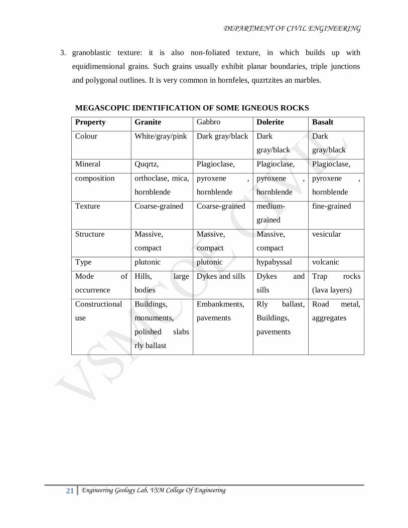
MEGASCOPIC IDENTIFICATION OF SOME IGNEOUS ROCKS
Property Granite Gabbro Dolerite Basalt
Colour White/gray/pink Dark gray/black Dark
gray/black
Dark
gray/black
Mineral Quqrtz, Plagioclase, Plagioclase, Plagioclase,
composition orthoclase, mica,
hornblende
pyroxene ,
hornblende
pyroxene ,
hornblende
pyroxene ,
hornblende
Texture Coarse-grained Coarse-grained medium-
grained
fine-grained
Structure Massive,
compact
Massive,
compact
Massive,
compact
vesicular
Type plutonic plutonic hypabyssal volcanic
Mode of
occurrence
Hills, large
bodies
Dykes and sills Dykes and
sills
Trap rocks
(lava layers)
Constructional
use
Buildings,
monuments,
polished slabs
rly ballast
Embankments,
pavements
Rly ballast,
Buildings,
pavements
Road metal,
aggregates
Page 22
DEPARTMENT OF CIVIL ENGINEERING
22 Engineering Geology Lab, VSM College Of Engineering
MEGASCOPIC IDENTIFICATION OF SOME SEDIMENTARY ROCKS
Property Sand stone Shale Lime
stone
Conglomerate Laterite
Colour varies varies varies varies
Mineral Quqrtz, Clay mineral calcite Rounded rock clay
composition Feldspar
(minor)
dolomite Pebbles
cemented
Fe & Al
Texture Coarse-
grained
medium-
grained
fine-grained fine-
grained
Coarse-
grained
Structure stratified laminated compact Assorted
pebbles
porous
Mode of
occurrence
stratified stratified stratified As thin strata Residual
Constructional
use
monuments,
pavements
- Slabs, tiles Buildings Buildings
Page 23
DEPARTMENT OF CIVIL ENGINEERING
23 Engineering Geology Lab, VSM College Of Engineering
MEGASCOPIC IDENTIFICATION OF SOME METAMORPHIC ROCKS
Property quartizite marble slate schist Gneiss khondalite
Colour White/gray White/gray/pink varies varies varies Gray-
brown
Mineral Quqrtz, calcite Clay
mineral
Quqrtz,
mica,
Quqrtz, Quqrtz,
composition Feldspar,
mica,
dolomite Quqrtz,
mica,
hornblende Feldspar,
hornblende
Feldspar,
garnet
Texture Coarse-
grained
compact laminated coarse-
grained
Coarse to
medium
Coarse to
medium
Structure compact banded Slaty
cleavages
foliation
schistose Gneissic
banding
schistose
Source rock Sand stone Lime stone Shale Shale Granite Igneous
Constructional
use
Road
metal,
slabs,
blocks
Slabs,tiles Slabs,tiles Road
metal,
temples
Property charnockite
Colour Gray- Dark gray,bluish-gray
Mineral composition Quqrtz, Feldspar,hypersthene
Texture Medium- fine grained
Structure Banded/foliated
Source Igneous rock
Constructional use
Page 24
DEPARTMENT OF CIVIL ENGINEERING
24 Engineering Geology Lab, VSM College Of Engineering
STRUCTURAL GEOLOGY
Type-I: problems related to thickness of strata
Type-II : problems related to strike and dip
Type-III : bore hole problems
Type-I: problems related to thickness of strata(exp.n0.8)
AIM: To determine the given to thickness of strata by graphical method.
Introduction:
Thickness of a bed is the shortest distance between its upper and lower surfaces. In other words it
is the perpendicular drawn to both the surfaces and it is known as TRUE THICKNESS [TT]
When a vertical bore hole is sunk on the inclined beds, it reaches the upper and lower surfaces at
different levels. The difference is known as VERTICAL THICKNESS [VT]. When a bed is
exposed on the ground it is an outcrop. An inclined bed is outcropped on a horizontal ground, its
upper and lower surfaces are found parallel to each other. The distance between the two surfaces
(bedding planes) is called WIDTH OF OUTCROP [WO]. It is usually measured along the dip
direction. Dip of an inclined bed is always expressed by its direction [Dd] and amount of dip
[DA]
All these factors viz true thickness [TT],
vertical thickness [VT], width of outcrop [WO], dip direction [Dd] and amount of dip [DA] are
interrelated. When some of them are known, the other can be determined by graphical method. In
graphical method, figures are drawn to a conventional scale and solutions are obtained.
THICKNESS PROBLEMS:
Note: (1) the dip angle is equal to the angle between the true thickness and vertical thickness
(2) Vertical thickness is always greater than true thickness.
1. Type-I: Date given – W and D (A) +D (d)
To determine –TT and VT.
Example: a coal seam is exposed on horizontal ground. It dips 30° westward. Its width of
outcrop is 360 m. determine true thickness and vertical thickness.
Procedure: draw a horizontal line. Measure and mark AB equal to width of outcrop given.
Construct 30° angle westward at A and B. draw a perpendicular to the lower surface from A. it is
the true thickness= 180 m.
Page 25
DEPARTMENT OF CIVIL ENGINEERING
25 Engineering Geology Lab, VSM College Of Engineering
Draw a perpendicular to AB downwards from A. it cuts the lower surface at P.
Measure ad it is the vertical thickness = 120 m.
2. Type-II: Date given – W+D (d) + VT
To determine –TT + D (a)
Example: a coal seam is exposed on level ground. It dips northward. Its width of outcrop is
180 m. a bore hole sunk from its upper bedding plane touches the lower bedding plane at a
depth of 105 m. determine true thickness and amount of inclination.
Procedure: draw a horizontal line. Mark south-north Measure AB width of outcrop. Draw a
perpendicular at B downwards. Measure 105 mts, mark D, BD is vertical thickness, join AD
and extend downward. It is lower bedding plane. Draw upper bedding plane from B parallel to
AD. Draw perpendicular from B TO AD. It cuts AD at C. BC is true thickness. Measure BC =
90 m.
Measure dip angle BAD = 30°
3. Type-III: Date given – TT+D (a) + D (d)
To determine –VT + W
Example: on a horizontal tunnel, a bed of sand-stone dips 30° eastward. Its true thickness is
200 m. determine vertical thickness and width of outcrop in the tunnel.
Procedure: draw a horizontal line XY. Mark B point. Construct YBZ-30° dip angle eastward.
BZ is upper surface of sandstone. Draw perpendicular to BZ at B downward. Measure 200 mts,
mark C.BC is the true thickness, draw parallel to BZ from C. it cuts the XY line at A. Measure
AB = width of out crop = 400 m.
4. Type-IV: Date given – VT + Dip
To determine –TT + W
Example: a vertical bore hole sunk from the upper bedding plane of a shale bed reaches the
lower bedding plane at a depth of 150 m. it dips 35° westwards. Determine true thickness and
width of outcrop on level ground.
Procedure: draw a horizontal line XY. Mark A point. Construct XAZ-35° dip angle westward.
AZ IS The upper surfaces. Draw perpendicular to XY from A downward. Mark D point at a
depth of 150 m. draw parallel to AZ from D. it cuts the XY line at B. BD is lower bedding plane.
Measure AB=W=218 m.
Page 26
DEPARTMENT OF CIVIL ENGINEERING
26 Engineering Geology Lab, VSM College Of Engineering
Type-II: problems- strike and dip problems (Exp .No 9)
AIM: To determine the given to thickness of strata by graphical method.
Introduction:
In all inclined beds, dip and strike are co-existing and they are mutually perpendicular.
TRUE DIP is maximum amount of inclination and it is only one, which is always perpendicular
to strike direction. But dips are often measured in the adjacent direction of the true dip. They are
always less than the true dip. They are in between true dip and strike directions. Farther away
from the true dip direction, they become less and zero along the strike direction. Such dips are
known as APPARENT DIPS. They are many on either side of true dip.
Note: true dip apparent dips are interrelated. They can be determined from the available date
from the field or map. Dip and strike problems can be solved by graphical method.
1. Type-I:
Date known- 2 apparent dips - directions and amount.
To determine true dip, direction and amount.
Example: A bed of sandstone dips 30° along S 35°W and 38° along N 60°W. Determine its true
dip by graphical.
Procedure: draw north-south and east-west lines. Let them intersect O. describe a vector circle-
O its center with convenient radius (preferably 2.5 cm).
Draw OA along apparent dip S 35°W (AD1). draw a perpendicular to it at O. it intersects the
circle at R. construct complementary angle of the given apparent dips (90°-30°) 60° at P. it cuts
O at M . OMR=30°.
Similarly draw OB along apparent dip N 60°W (AD2). draw a perpendicular to it at O. IT cuts
the circle at P. construct complementary angle of the given apparent dips (90°-38°) 52° at P. it
cuts OB at Q. angle OQP=38° join MQ. It forms the true strike direction (TSD) to determine the
direction of true dip, draw a perpendicular to TSD from O. it cuts the TSD line at X; OX is the
direction of true dip. Measure angle SOX. It is S 85°W.
To determine the amount of true dip along OX draws a perpendicular to it at O. it cuts the circle
at Y, join XY. Measure angle OXY. It is 42°
TRUE DIP - 42° along S 35°W.
2. Type-II
Date given- TD (amount & direction)
Page 27
DEPARTMENT OF CIVIL ENGINEERING
27 Engineering Geology Lab, VSM College Of Engineering
AD1 (direction)
To determine AD (amount)
Example: A bed of shale is dipping maximum of 32° along SE. find the amount of its
inclination along S 80°E.
Procedure: draw north-south and east-west lines. Let them intersect O. describe a vector circle-
O. draw true dip directional line OP along SE. draw a perpendicular to OP at O. It cuts the circle
at A. construct complementary angle of true dips (90°-32°) 58° at A.. It cuts OP line at B. draw
a perpendicular to OP at B. it is strike direction (TSD).
Draw apparent dip direction line OQ. It cuts TSD line at Y. draw a perpendicular to OQ at O. it
cuts the circle at X join XY. Measure angle OXY=26°.
3. Type-III: Date given: TD+AD (amt)
To determine AD1 (direction).
Example: a coal seam is overlying sandstone and has a maximum dip of 42° towards south; two
inclined tunnels are proposed on the upper bedding plane of sandstone to have an inclination of
30°. Determine the direction of the tunnels.
Procedure: draw north-south and east-west lines. Let them intersect O. describe a vector circle-
O. Draw true dip directional line along OS. Draw a perpendicular to it at O. it intersects the
circle at P. Construct complementary angle of true dips (90°-42°) 48° at P.. it cuts OS line at Q.
draw a perpendicular to OS at Q. it is true strike direction (TSD).
To plot the direction of apparent dip, select arbitrarily any suitable direction. Let us take OE.
Draw perpendicular ON. It cuts the circle at X. construct the complementary angle of apparent
dip (90°-30°) 60° at X. it cuts OE line at Y. angle OYX is 30°.
With O as center and OY as radius, draw a circle to cut TSD at A and B. join OA and OB.
Measure angle SOA and angle SOB. They are S 50°W and S 50°E
. 4. Type-IV:
Date given: apparent dip- direction and amount, TD direction
To determine: T.D-amount.
Example: a coal seam has an apparent dip of 35° along S 35°E. The maximum dip is S 10°W.
Calculate the amount of true dip a coal seam.
Procedure: draw north-south and east-west lines. Let them intersect O. describe a vector circle
of 2.5 cm radius from O. draw apparent directional line OA along S 35°E . Draw a
Page 28
DEPARTMENT OF CIVIL ENGINEERING
28 Engineering Geology Lab, VSM College Of Engineering
perpendicular to it at O. . It cuts the circle at B. construct the complementary angle of apparent
dip (90°-35°) 55° at B. it cuts OA line at X.
Draw true dip directional line OC along S 10°W. Draw a perpendicular to OC-TD line from X. it
cuts OC at D. DX is true strike direction (TSD). Draw a perpendicular to OC at O. it cuts the
circle at E. join FD measure angle FDC. It is 44°.
Type-III: problems - borehole problems
Introduction:
In order to determine the subsurface geology of an area, boreholes are sunk at convenient
places. In areas such as cultivated lands, forests, deserts, alluvium etc the surface is completely
covered and outcrops are very few. Such boreholes reveal the presence of economic deposits of
coal, petroleum etc, the subsurface geological formations, rock types and their dip and strike can
be determined from such borehole data, which render very valuable information for planning for
exploiting the hidden treasures.
Example: three boreholes are sunk at 3 points of an equilateral triangle whose sides are 480m
each. P is west of Q and R is north of midpoint PQ. Boreholes P, Q and R reach the upper
surface of a rich coal seam at 100m, 220m and 260m depth respectively (a) determine the
attitudes (dip and strike) of the coal seam, (b) ) another borehole is sunk at S – midpoint of QR.
determine at what depth the borehole S reaches the same coal seam. If it is actually touches at
360m. Determine the geological structure. Scale 1Cm = 100m
Procedure:
Construct an equilateral triangle with a suitable scale. Show the position of the borehole.
The coal seam is reached at P and Q at 100m and 220m. so the coal seam dips from P to Q. To
determine the inclination along PQ construct rough sketch (a) depth diagram and determine the
gradient. It is 120m in 480m. So it is 1 in 4. Similarly construct depth diagram along PR. It is
160m in 480m i.e. 1 in 3. Take convenient scale and mark 4 units (cms) along PQ and 3 units
(cms) along PR from P. they are A and B join AB and extend. It is true strike direction (TSD).
Drop a perpendicular to AB from P. it cuts AB at C. measure PC. It is 2.85 cms i.e. the gradient
is 1 in 2.85. it is true dip.
To determine the direction of true dip, measure the angle CPQ = 45° SO the direction of true
dip is the complementary angle from north direction. So (90°-45°) 45°. So it is N 45°E.
True dip. - 1 in 2.85 along NE. strike – SE and NW.
. To determine the depth at which the borehole ‘S’ reaches the same coal seam, join PS. It
intersects AB line (true strike direction) at T. measure PT with units selected. It is 3cm. so the
gradient along PT is 1 in 3. Measure PS. It is 4.2 cm = 420m.
Page 29
DEPARTMENT OF CIVIL ENGINEERING
29 Engineering Geology Lab, VSM College Of Engineering
Depth = (horizontal distance PS x gradient) + depth of borehole at P.
= (420 X 1/3) + 100m
= 140m + 100m = 240m
Determine the geological structure: in the borehole ‘S’ the Depth calculated is 240mts. But it is
reaching the formation at 360mts, May indicative of faulting.
DETERMINATION OF GEOLOGICAL STRUCTURES:
Introduction:
In order to determine the subsurface geology of an area, boreholes are sunk at convenient places.
In areas such as cultivated lands, forests, deserts, alluvium etc the surface is completely covered
and outcrops are very few. Such boreholes reveal the presence of economic deposits of coal,
petroleum etc, the subsurface geological formations, rock types and their dip and strike can be
determined from such borehole data, which render very valuable information for planning for
exploiting the hidden treasures.
Example: three boreholes are sunk at 3 points of an equilateral triangle whose sides are 480m
each. P is west of Q and R is north of midpoint PQ. Boreholes P, Q and R reach the upper
surface of a rich coal seam at 100m, 220m and 260m depth respectively (a) determine the
attitudes (dip and strike) of the coal seam, (b) ) another borehole is sunk at S – midpoint of QR.
determine at what depth the borehole S reaches the same coal seam. If it is actually touches at
360m. Determine the geological structure. Scale 1Cm = 100m
Procedure:
Construct an equilateral triangle with a suitable scale. Show the position of the borehole.
The coal seam is reached at P and Q at 100m and 220m. so the coal seam dips from P to Q. To
determine the inclination along PQ construct rough sketch (a) depth diagram and determine the
gradient. It is 120m in 480m. So it is 1 in 4. Similarly construct depth diagram along PR. It is
160m in 480m i.e. 1 in 3. Take convenient scale and mark 4 units (cms) along PQ and 3 units
(cms) along PR from P. they are A and B join AB and extend. It is true strike direction (TSD).
Drop a perpendicular to AB from P. it cuts AB at C. measure PC. It is 2.85 cms i.e. the gradient
is 1 in 2.85. it is true dip.
To determine the direction of true dip, measure the angle CPQ = 45° SO the direction of true
dip is the complementary angle from north direction. So (90°-45°) 45°. So it is N 45°E.
True dip. - 1 in 2.85 along NE. strike – SE and NW.
Page 30
DEPARTMENT OF CIVIL ENGINEERING
30 Engineering Geology Lab, VSM College Of Engineering
. To determine the depth at which the borehole ‘S’ reaches the same coal seam, join PS. It
intersects AB line (true strike direction) at T. measure PT with units selected. It is 3cm. so the
gradient along PT is 1 in 3. Measure PS. It is 4.2 cm = 420m.
Depth = (horizontal distance PS x gradient) + depth of borehole at P.
= (420 X 1/3) + 100m
= 140m + 100m = 240m
Determine the geological structure: in the borehole ‘S’ the Depth calculated is 240mts. But it is
reaching the formation at 360mts, May indicative of faulting.
Page 31
DEPARTMENT OF CIVIL ENGINEERING
31 Engineering Geology Lab, VSM College Of Engineering
GEOLOGY MAP STUDY
1. AIM:
To draw the cross section of geological maps.
2. MATERIALS:
Geological map, white paper, pencil, eraser, scale, set squares.
3. PROCEDURE:
Draw a profile of the map along the straight line X-Y fig.
Place the paper strip (A-B) again on the X-Y line of the map, this time mark the points of
intersection of bedding planes on the edge of the paper strip shown in fig.
Now Place the paper strip again on the base of the profile so that the points X-Y on the
paper strip coincide with the X-Y of the profile as shown in fig
Now transfer all the bedding planes points of bedding planes marked on the paper to base
of the profile as shown in fig. and through them other perpendicular with dotted lines to
meet the profile.
All the beds in fig. are dipping at angle of a towards X, draw a straight line R-S inclined
to X-Y at an angle 0 towards X.
Now through ‘O’ and ‘P’ draw parallel line to RS as OO’ and PP’ at an angle 0 towards
X. and they are the bottom of the bed.
Name the beds as per their depositional order i.e. C---B- A as seen in the Geological
section. to Name the beds, proceed from ‘X’ to ‘Y’ or ‘Y’ to ‘X’ in map fig. if you are
walking from ‘Y’ to ‘X’ immediately after the point ‘Y’ you are stepping into the bed
‘C’, hence the bed in the section (fig) after the point ‘Y’ is the ‘C’ followed by ‘B’ and
the ‘A’ as shown in Geological section (figs 4a.1 – 4a.7)
STUDY AND INTERPRETATION:
1. AIM:
To study and interpretation of given geological maps.
2. MATERIALS:
Geological map, white paper, pencil, eraser, scale, set squares.
3. PROCEDURE:
In the interpretation of geological section, when there are more than one series
present, younger beds must be drawn first, followed by the older. The older beds are
Page 32
DEPARTMENT OF CIVIL ENGINEERING
32 Engineering Geology Lab, VSM College Of Engineering
always projected to the base of the younger beds but not to the profile. Caution is
necessary in drawing the dip directions.
When the same bedding planes are repeated in a map it is necessary to calculate the
amount and directions of the dip as many times as the bedding planes are repeated.
The repetition of the bed may be an identification of the fold. It is evidenced by the
reversal of dip directions of the bedding planes.
An unconformity (a layer separating the older series of beds from the younger series)
may be identified in the map by truncation of the older series, i.e. against a line
(uniformity) the beds of older series are abruptly ending, where as the younger series
generally extend from one end of the map to the other end. When uniformity is
noticed in a map, calculate the amount and directions of the dip for older and younger
series. The unconformity in a Geological section is represented by a corrugated line
(…….)
Repetition of beds may be due to folding of the beds.
a) Repetition is due to folding, it is indicated by the reversal of dip direction of the
same bedding planes. It is due to fault it is recognized by a presence of a fault
line which may be a straight or curved (Note – the fault line should be treated as a
bed and its attitude is determined.)
b) If there is discontinuity of the against the fault line.
c) Some times change in the attitude of the beds on the other side of the fault plane.
d) Beds may be repeated or omitted
Recognition of horizontal, vertical beds in a geological map.
a) Horizontal beds: in a geological map when the bedding planes run parallel to the
contour lines the beds are horizontal (fig)
Note: when the beds are horizontal there is necessity of calculating dip. The beds in
profile are represented parallel to the line as shown in fig.
b) Vertical beds: the vertical beds in a geological map can be recognized by drawing the
strike line. When the strike lines are drawn, they pass one above the other, i.e. there will
not be any strike intervals shown in fig.
c)inclined beds are Recognized in a geological map, when the contour cut the bedding
planes there will be a strike interval and hence the beds will have inclination fig.
Note: when the strike interval increases dip decreases. when the strike interval decreases
dip increases.
Page 33
DEPARTMENT OF CIVIL ENGINEERING
33 Engineering Geology Lab, VSM College Of Engineering
COMPLETION OF OUT CROPS
1. AIM:
Completion of out crops.
2. MATERIALS:
Geological map, white paper, pencil, eraser, scale, set squares.
3. PROCEDURE:
A geological map is shown.
X-Y is the reference line along which the profile has to be drawn.
Strike line: to draw a strike line select a bedding planes, this is intersected by the same
contour line at two points. For example the bedding planes are intersected by the 150mts
contour line at two points ’a’ and ‘b’. As these two points are at equal elevation, they are
joined and extended to the boundary of the map (MN) by a straight line. As the line is
drawn at the height of 150mts. The value of the strike line is also 150mts. So the line MN
is a strike line drawn for the A/B bedding planes A/B is now striking direction north-
south.
It is possible to drawn some more strike lines for the same bedding planes at other
elevation such as 100mts, 200mts, and 250mts. All these strike lines will be parallel to
each other because they were drawn at different elevation for the same bedding planes.
The perpendicular distance in fig measured between the two successive strike lines is the
strike interval.
Note: to draw a second strike lines if the bedding planes is intersected by the other
contour line only at the one place draw a parallel line to the first strike lines through that
single point of intersection. In the fig. a strike lines MN is drawn for the bedding planes
A/B because the bedding planes is intersected by the 250mts contour at the two points a
and b where as the strike lines OP is drawn parallel to MN through the point C which is
the only point of intersection between the bedding and where the bedding plane A/B is
intersecting contour at 200mts. Following with the above procedure you can draw the
strike lines for any given bed in a Geological map.
Dip : Dip is the inclination made by the bedding planes with the horizontal. The amount
of dip is calculated by knowing the strike interval and contour interval.
Page 34
DEPARTMENT OF CIVIL ENGINEERING
34 Engineering Geology Lab, VSM College Of Engineering
Contour interval
Dip= -----------------------------
Strike interval
Dip is also known by geometrical method where a right angle is constructed taking Strike
interval as the base and the Contour interval as the perpendicular to the base. The
procedure is as follows:
Draw two successive Strike lines for the same bedding plane
Measure the perpendicular distance (a-b) between the two successive Strike lines as
shown in fig. which gives the “Strike interval”
Note the interval between two contour lines are drawn as the Contour interval in fig. it is
50mts. Draw a straight line with a length equal to Strike interval as per the scale. In fig ab
is the Strike interval.
Draw a normal at ‘b’ or ‘a’ with a length equal to the Contour interval as per the scale. In
fig be represent the Contour interval.
Join ‘a’ and ‘c’ and measure the angle (bac) which is the amount of dip.
The directions of the dip is always perpendicular to the Strike from a higher Contour
value as indicated by arrows in fig. as there is a reference line X-Y, the directions of the
dip of the bed can be mentioned with reference to ‘X’, ‘Y’.
Note: as we are drawing a Geological section for the interpretation of the Geological
structure along the given reference line X-Y, the amount of dip calculated measuring the
Strike interval measured along the given reference line is perpendicular to the Strike line
(fig ‘ab’ along X-Y)
the amount of dip is true dip. When the Strike interval is measured (CD) along the
reference line X1-Y1 (FIG) is not perpendicular to the Strike line, the amount of dip is
“apparent dip”
Page 35
DEPARTMENT OF CIVIL ENGINEERING
35 Engineering Geology Lab, VSM College Of Engineering
UTILIZATION OF GEOLOGICAL MAPS TO PREPARE FEASIBILITY REPORT
FOR CIVIL ENGINEERING CONSTRUCTION WORKS/PROJECTS:
1. AIM:
Utilization of geological maps to prepare feasibility report for civil engineering construction
works/projects.
2. MATERIALS:
Geological map, white paper, pencil, eraser, scale, set squares.
3. PROCEDURE:
In the interpretation of geological section, when there are more than one series
present, younger beds must be drawn first, followed by the older. The older beds are
always projected to the base of the younger beds, but not to the profile. Caution is
necessary in drawing the dip direction.
When the same bedding planes are repeated in a map it is necessary to calculate
the amount and direction. Of the dips many times as the bedding planes are repeated.
The repetition of the beds may be an identification of a fold. It is evidenced by the
reversal of dip direction of the same bedding planes.
An unconformity (a layer separating the older series of beds from the younger
series) may be identified in the map by truncation of the older series, i.e. against a
line (uniformity) the beds of older series are abruptly ending, where as the younger
series generally extend from one end of the map to the other end. When uniformity is
noticed in a map, calculate the amount and directions of the dip for older and younger
series. The unconformity in a Geological section is represented by a corrugated line
(…….)
Repetition of beds may be due to folding of the beds.
e) Repetition is due to folding, it is indicated by the reversal of dip direction of the
same bedding planes. It is due to fault it is recognized by a presence of a fault
line which may be a straight or curved (Note – the fault line should be treated as a
bed and its attitude is determined.)
f) If there is discontinuity of the against the fault line.
g) Some times change in the attitude of the beds on the other side of the fault plane.
h) Beds may be repeated or omitted
Recognition of horizontal, vertical beds in a geological map.
b) Horizontal beds: in a geological map when the bedding planes run parallel to the
contour lines the beds are horizontal (fig)
Page 36
DEPARTMENT OF CIVIL ENGINEERING
36 Engineering Geology Lab, VSM College Of Engineering
Note: when the beds are horizontal there is necessity of calculating dip. The beds in
profile are represented parallel to the line as shown in fig.
b) Vertical beds: the vertical beds in a geological map can be recognized by drawing the
strike line. When the strike lines are drawn, they pass one above the other, i.e. there will
not be any strike intervals shown in fig.
c)inclined beds are Recognized in a geological map, when the contour cut the bedding
planes there will be a strike interval and hence the beds will have inclination fig.
Note: when the strike interval increases dip decreases. when the strike interval decreases
dip increases. By means of above observation the feasibility report is prepared for a given
project.