Progress In Electromagnetics Research C, Vol. 61, 161–170, 2016 Miniaturization of Dipole Antenna for Low Frequency Ground Penetrating Radar Md O. F. Howlader * and Tariq P. Sattar Abstract—In this paper, a miniaturized dipole antenna operating at 100 MHz frequency for Ground Penetrating Radar (GPR) application is presented. A conventional dipole antenna length is half of its lowest operating frequency wavelength. As low frequency GPR system is vital for high depth penetration, the size of the antenna used reduces its easy handling and portability. Therefore, the technique of miniaturizing a dipole antenna by adding extra radiating arms is presented here. The antenna design and analysis is carried out using Advanced Design System (ADS) and FEKO simulation software, and a network analyser is used to validate the prototype antenna performance. The antenna of 66.5 × 22 cm dimension, fabricated on an FR4 substrate exhibits a frequency resonance at 104 MHz with 8 MHz of −10 dB bandwidth. The proposed antenna radiates in omnidirectional pattern and features 55% reduction in length compared to a conventional dipole antenna of same frequency operation. 1. INTRODUCTION Ground Penetrating Radar (GPR) is a Non-Destructive Testing (NDT) equipment that find its application in archaeological and military fields that use electromagnetic waves to detect and identify buried objects and structures [1]. GPR is required to accurately resolve the depth, orientation, size and shape of buried objects and can be applied to find the positions of buried targets with an accuracy of about 3 cm at depths up to 50 m [2]. The operating frequency band of GPR ranges from 10 MHz to a few GHz, depending on the measurement and penetration depth requirements. A higher frequency GPR system emits narrower pulses in picosecond region, yielding a higher time and depth resolution. However, the depth penetration of high frequency signal is low as signal attenuation increases with frequency [3]. Whereas a low frequency system has a lower depth resolution but higher depth penetration as given in Table 1. Moreover, GPR can be best implemented in dry subsurface sand, gravel and pit, but the presence of moisture in the media can cause minor signal attenuation. As in [4] severe signal attenuation problems were found in slit, clay with moist saline conditions. Therefore, low frequency GPR systems are ideally suited for outdoor geotechnical, archaeological and environmental applications where moisture is a regular occurrence and high depth penetration is highly desired. Antennas are essential components of GPR systems for transmission and reception of the electromagnetic waves. Efficient emitting and receiving of electromagnetic energy is ensured by high antenna gain as antennas with a high gain improve the signal-to-noise ratio [3]. As physical size and gain of antennas are determined by the operating frequency, small antennas offer compact system dimension. However, small antennas have a low gain at lower frequencies, and larger antennas are required to operate at lower frequencies. Various types of antennas are used for GPR systems, but dipole and bow-tie antennas are most common as they are easy to fabricate on a variety of substrates because of planer surface structure [6]. Theoretically, the length of a dipole antenna is half of its lowest operating wavelength. Few samples of Received 30 October 2015, Accepted 10 January 2016, Scheduled 21 January 2016 * Corresponding author: Md Omar Faruq Howlader ([email protected]). The authors are with the Robotic and NDT Research Centre, London South Bank University, UK.
Transcript
Progress In Electromagnetics Research C, Vol. 61, 161–170, 2016
Miniaturization of Dipole Antenna for Low Frequency GroundPenetrating Radar
Md O. F. Howlader* and Tariq P. Sattar
Abstract—In this paper, a miniaturized dipole antenna operating at 100 MHz frequency for GroundPenetrating Radar (GPR) application is presented. A conventional dipole antenna length is half ofits lowest operating frequency wavelength. As low frequency GPR system is vital for high depthpenetration, the size of the antenna used reduces its easy handling and portability. Therefore, thetechnique of miniaturizing a dipole antenna by adding extra radiating arms is presented here. Theantenna design and analysis is carried out using Advanced Design System (ADS) and FEKO simulationsoftware, and a network analyser is used to validate the prototype antenna performance. The antenna of66.5×22 cm dimension, fabricated on an FR4 substrate exhibits a frequency resonance at 104 MHz with8MHz of −10 dB bandwidth. The proposed antenna radiates in omnidirectional pattern and features55% reduction in length compared to a conventional dipole antenna of same frequency operation.
1. INTRODUCTION
Ground Penetrating Radar (GPR) is a Non-Destructive Testing (NDT) equipment that find itsapplication in archaeological and military fields that use electromagnetic waves to detect and identifyburied objects and structures [1]. GPR is required to accurately resolve the depth, orientation, size andshape of buried objects and can be applied to find the positions of buried targets with an accuracy ofabout 3 cm at depths up to 50 m [2]. The operating frequency band of GPR ranges from 10 MHz to afew GHz, depending on the measurement and penetration depth requirements. A higher frequency GPRsystem emits narrower pulses in picosecond region, yielding a higher time and depth resolution. However,the depth penetration of high frequency signal is low as signal attenuation increases with frequency [3].Whereas a low frequency system has a lower depth resolution but higher depth penetration as givenin Table 1. Moreover, GPR can be best implemented in dry subsurface sand, gravel and pit, but thepresence of moisture in the media can cause minor signal attenuation. As in [4] severe signal attenuationproblems were found in slit, clay with moist saline conditions. Therefore, low frequency GPR systems areideally suited for outdoor geotechnical, archaeological and environmental applications where moistureis a regular occurrence and high depth penetration is highly desired.
Antennas are essential components of GPR systems for transmission and reception of theelectromagnetic waves. Efficient emitting and receiving of electromagnetic energy is ensured by highantenna gain as antennas with a high gain improve the signal-to-noise ratio [3]. As physical size and gainof antennas are determined by the operating frequency, small antennas offer compact system dimension.However, small antennas have a low gain at lower frequencies, and larger antennas are required to operateat lower frequencies.
Various types of antennas are used for GPR systems, but dipole and bow-tie antennas are mostcommon as they are easy to fabricate on a variety of substrates because of planer surface structure [6].Theoretically, the length of a dipole antenna is half of its lowest operating wavelength. Few samples of
Received 30 October 2015, Accepted 10 January 2016, Scheduled 21 January 2016* Corresponding author: Md Omar Faruq Howlader ([email protected]).The authors are with the Robotic and NDT Research Centre, London South Bank University, UK.
162 Howlader and Sattar
Table 1. Depth penetration and resolution for GPR systems with different frequencies [5].
Antenna Frequency (MHz)2000 900 500 300
Resolution, m 0.04–0.08 0.2 0.5 1.0Depth, m 1.5–2 3–5 7–10 7–10
Blind Zone, m 0.06 0.1–0.2 0.25–0.5 0.5–1.0
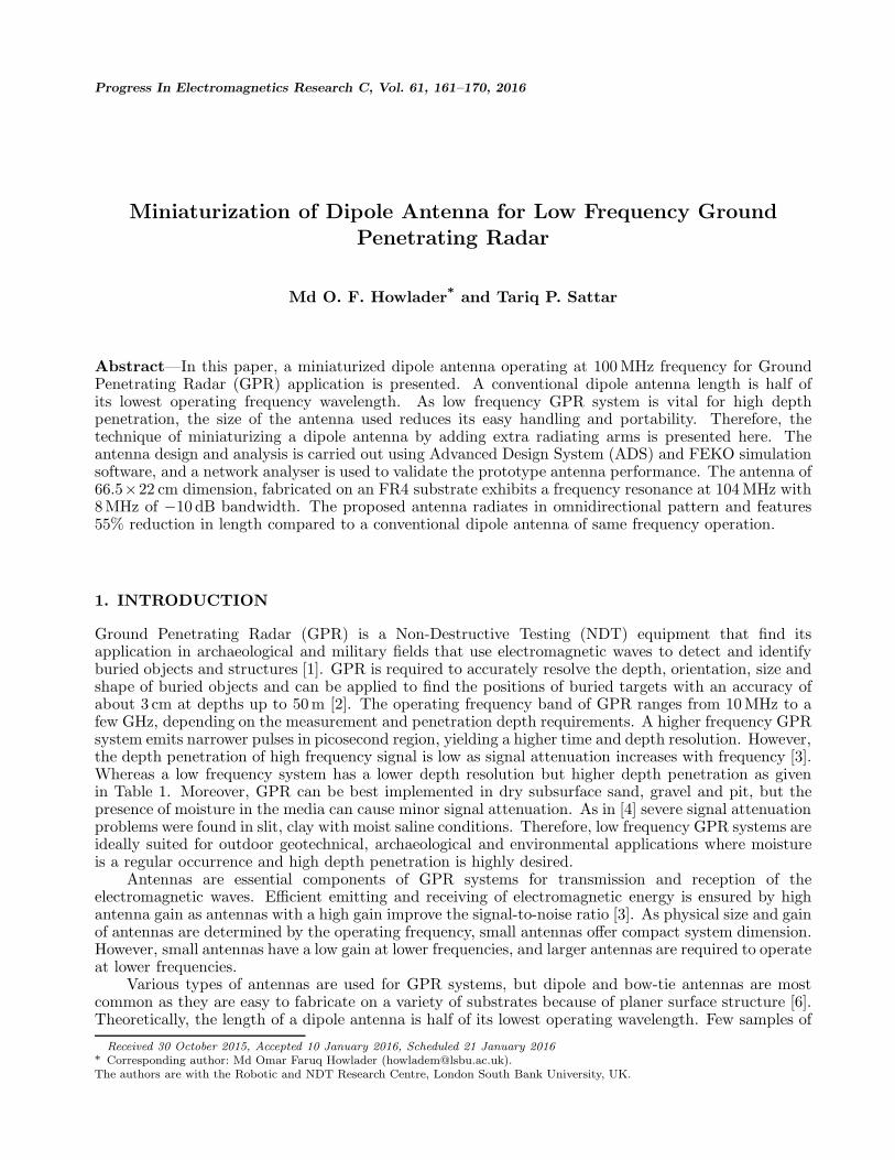
Figure 1. Archaeological GPR scanning with 100 MHz unshielded and shielded dipole antenna [7].
dipole antennas for different frequencies given in Figure 1 show that, due to the low frequency operation,the antenna size is quite an issue since the antenna size determines the whole system size and portability.
The half-wavelength size of 1.5 m at 100 MHz is considerably large; therefore, it is very desirableto miniaturize the dipole antenna length in order to scale down the whole system size.
In this paper, a technique is applied to the conventional 100 MHz dipole antenna to minimizeits length by approximately 55%. Reduction in length is achieved by introducing multiple sets ofradiating arm at a certain distance from the primary dipole arms. Agilent Advance Design System(ADS) and FEKO software platform are used in order to examine the antenna resonance and radiationcharacteristics. The paper consists of the following sections: Section 2 gives an overview of the existingantenna miniaturization techniques. Section 3 describes the proposed miniaturized dipole antennadesign and design parameters. The simulation results of those parameters on antenna bandwidth,resonance frequency and directivity gain are presented in Section 4. Section 5 presents the fabricationprocess of the antenna and experimental setup for antenna performance verification, and finally, thepaper concludes with a brief summary and recommendation in Section 6.
2. ANTENNA MINIATURIZATION TECHNIQUES
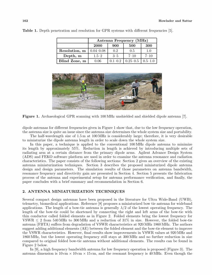
Several compact design antennas have been proposed in the literature for Ultra Wide-Band (UWB),telemetry, biomedical applications. Reference [8] proposes a miniaturized bow tie antenna for widebandapplications. The length of a bow-tie antenna is generally λ/2 of the lowest operating frequency. Thelength of the bow-tie could be shortened by connecting the right and left arms of the bow-tie withthin conductor called folded elements as in Figure 2. Folded elements bring the lowest frequency forVSWR ≤ 2 from 540 MHz to 300 MHz and a reduction of 31% in size. However, the folded bow-tieantenna (FBTA) suffers from degradation of VSWR characteristics at 920 MHz 1860 MHz. The authorssuggest adding additional elements (AE) between the folded element and the bow-tie element to improvethe VSWR characteristics. However, final results show improvements in VSWR values at 920 MHz and1860 MHz, but the lowest operating frequency still stays at 300 MHz and no further reduction in sizecompared to original folded bow-tie antenna without additional elements. The results can be found inFigure 2 below.
In [9], a high frequency bandwidth antenna for low frequency operation is proposed (Figure 3). Theantenna dimension is 10 cm × 10 cm × 15 cm, and the resonant frequency is 40 MHz. Even though the
Progress In Electromagnetics Research C, Vol. 61, 2016 163
Figure 2. Bow-tie antenna with additional elements and their corresponding VSWR as proposed in [6].
Figure 3. The fabricated antenna in [7].
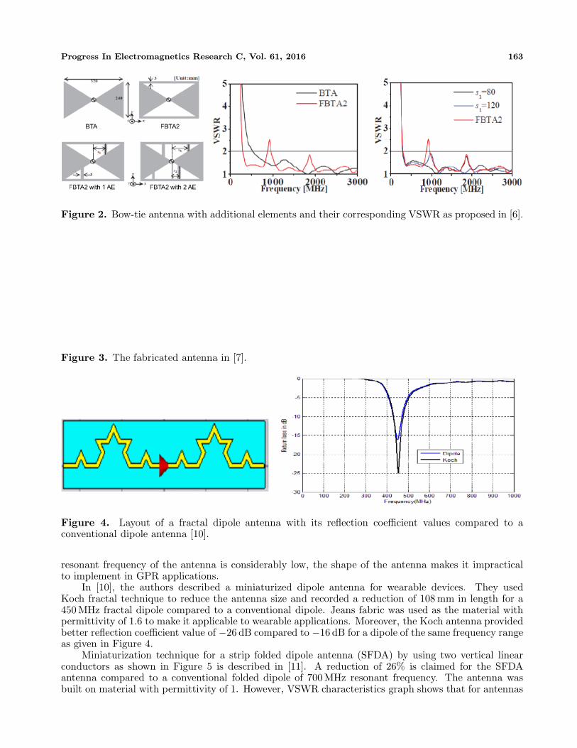
Figure 4. Layout of a fractal dipole antenna with its reflection coefficient values compared to aconventional dipole antenna [10].
resonant frequency of the antenna is considerably low, the shape of the antenna makes it impracticalto implement in GPR applications.
In [10], the authors described a miniaturized dipole antenna for wearable devices. They usedKoch fractal technique to reduce the antenna size and recorded a reduction of 108 mm in length for a450 MHz fractal dipole compared to a conventional dipole. Jeans fabric was used as the material withpermittivity of 1.6 to make it applicable to wearable applications. Moreover, the Koch antenna providedbetter reflection coefficient value of −26 dB compared to −16 dB for a dipole of the same frequency rangeas given in Figure 4.
Miniaturization technique for a strip folded dipole antenna (SFDA) by using two vertical linearconductors as shown in Figure 5 is described in [11]. A reduction of 26% is claimed for the SFDAantenna compared to a conventional folded dipole of 700 MHz resonant frequency. The antenna wasbuilt on material with permittivity of 1. However, VSWR characteristics graph shows that for antennas
164 Howlader and Sattar
Figure 5. Proposed SFDA antenna and its VSWR behaviour [11].
Figure 6. PFDA antenna and VSWR characteristics [13].
built on materials with higher permittivity such as 17.1, the resonant frequency can be lowered, butVSWR values worsen as a result.
Likewise, in [12] bow-tie antenna with folded elements of various inclinations have been studied.However, they offer no considerable improvements compared to conventional folder bow-tie antennaof the same resonant frequency. A planer folded dipole antenna with wide ground plane has beenproposed in [13]. The current distribution of the folded elements in Figure 6 shows that by loadingthe folded element of the antenna, the current at the upper edges increases strongly. It means thatimpedance characteristics of the antenna could be controlled by the current pathway at the edges offolded structure. However, VSWR results show that widening ground plane and folded arms do increasethe overall bandwidth of the antenna, but the resonant frequency stays at 1.35 GHz which is equal to aconventional dipole.
More examples of miniaturizing dipole and bow-tie antennas can be found in [14–17], etc. Butmost of the designs discuss antenna miniaturization techniques for high frequency UWB and RFIDapplications, hence, it is ideal to focus on miniaturization techniques of low frequency antennas.
3. MINIATURIZED DIPOLE ANTENNA DESIGN
In impulse GPR applications, short pulses, corresponding to wide bandwidth are used. An accuratetime-of-flight measurement is available at the receiving side because of the pulse’s high time resolution.In this paper, pulses with 10 ns duration are used as transmitting signals, corresponding to a 100 MHzcentre frequency operation. Figure 7 shows conventional dipole antenna characteristics for the 100 MHzresonance frequency. The material is FR4 with a dielectric constant of 4.4. Total length of the dipole is
Progress In Electromagnetics Research C, Vol. 61, 2016 165
Figure 7. Reflection coefficient and VSWR characteristics of dipole antenna.
Figure 8. Configuration of the proposed miniaturised dipole antenna for 100 MHz centre frequency.
1.5 m, and width is 15 mm. The reflection coefficient (S11) and VSWR graphs show that the bandwidthof the antenna is 8 MHz for VSWR ≤ 2 values.
The configuration of the proposed symmetric dipole antenna with multiple radiating arms operatingat 100 MHz is shown in Figure 8. The antenna is fed in the centre of its structure by 50 Ω coaxial cable.The radiating arms consist of 17 µm thick and 15 mm width copper layer. The whole radiating structureis set on an FR4 dielectric substrate of 1.6 mm thick.
The distance between the primary dipole arm and extra radiating arm is G, and length of thesecondary arms is L. In this paper, the antenna characteristics are investigated as the parameters arechanged to establish an optimum value for the dipole length reduction.
4. SIMULATION RESULTS
Every aspect of antenna dimension has an effect on the operating bandwidth and centre frequency.To understand the design criteria and their effect on overall antenna performance, antenna designoptimization was carried out by Moment of Method (MoM) based ADS and Finite Different TimeDomain (FDTD) based FEKO electromagnetic simulator to better comparison study. To establish theoptimum antenna design parameters, parametric studies of the distance between the primary dipolearm and extra radiating arms, g, and length of extra arms, l, were carried out.
4.1. Parametric Studies
Firstly, the effects of change in antenna arm’s length, l, from 300 mm to 15 mm are investigated. Theantenna feed gap is kept to 2mm for FR4 dielectric material. Figure 9 shows the reflection characteristicsof the antenna for various lengths. It is seen that long extra radiating arm length of 300 mm providesthe lowest resonance frequency operation of 137 MHz, but reflection coefficient, S11 value, is below−10 dB and is not acceptable for good performance. As the extra arm length is reduced to 250 mm, the
166 Howlader and Sattar
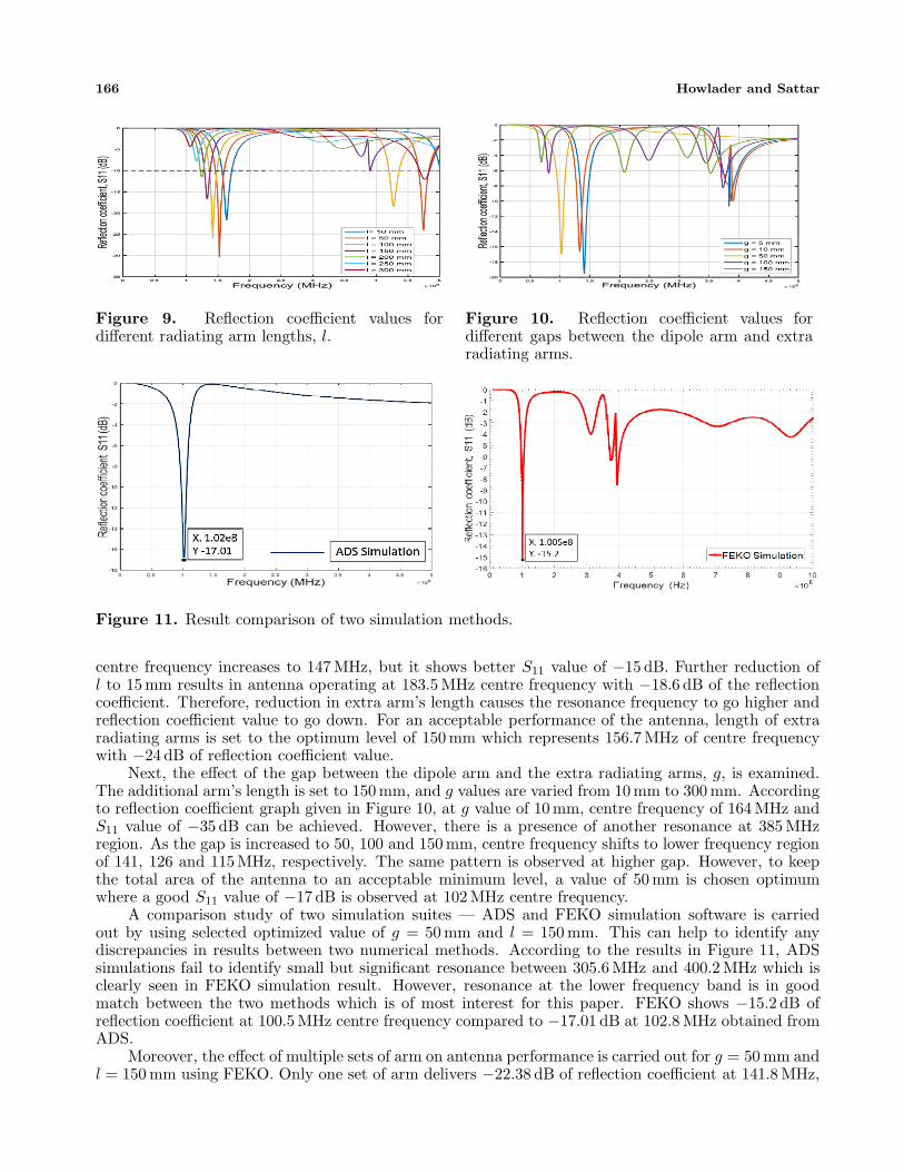
Figure 9. Reflection coefficient values fordifferent radiating arm lengths, l.
Figure 10. Reflection coefficient values fordifferent gaps between the dipole arm and extraradiating arms.
Figure 11. Result comparison of two simulation methods.
centre frequency increases to 147 MHz, but it shows better S11 value of −15 dB. Further reduction ofl to 15 mm results in antenna operating at 183.5 MHz centre frequency with −18.6 dB of the reflectioncoefficient. Therefore, reduction in extra arm’s length causes the resonance frequency to go higher andreflection coefficient value to go down. For an acceptable performance of the antenna, length of extraradiating arms is set to the optimum level of 150 mm which represents 156.7 MHz of centre frequencywith −24 dB of reflection coefficient value.
Next, the effect of the gap between the dipole arm and the extra radiating arms, g, is examined.The additional arm’s length is set to 150 mm, and g values are varied from 10 mm to 300 mm. Accordingto reflection coefficient graph given in Figure 10, at g value of 10 mm, centre frequency of 164 MHz andS11 value of −35 dB can be achieved. However, there is a presence of another resonance at 385 MHzregion. As the gap is increased to 50, 100 and 150 mm, centre frequency shifts to lower frequency regionof 141, 126 and 115 MHz, respectively. The same pattern is observed at higher gap. However, to keepthe total area of the antenna to an acceptable minimum level, a value of 50 mm is chosen optimumwhere a good S11 value of −17 dB is observed at 102 MHz centre frequency.
A comparison study of two simulation suites — ADS and FEKO simulation software is carriedout by using selected optimized value of g = 50 mm and l = 150 mm. This can help to identify anydiscrepancies in results between two numerical methods. According to the results in Figure 11, ADSsimulations fail to identify small but significant resonance between 305.6 MHz and 400.2 MHz which isclearly seen in FEKO simulation result. However, resonance at the lower frequency band is in goodmatch between the two methods which is of most interest for this paper. FEKO shows −15.2 dB ofreflection coefficient at 100.5 MHz centre frequency compared to −17.01 dB at 102.8 MHz obtained fromADS.
Moreover, the effect of multiple sets of arm on antenna performance is carried out for g = 50 mm andl = 150 mm using FEKO. Only one set of arm delivers −22.38 dB of reflection coefficient at 141.8 MHz,
Progress In Electromagnetics Research C, Vol. 61, 2016 167
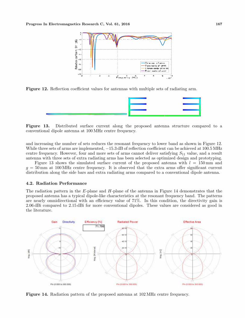
Figure 12. Reflection coefficient values for antennas with multiple sets of radiating arm.
Figure 13. Distributed surface current along the proposed antenna structure compared to aconventional dipole antenna at 100 MHz centre frequency.
and increasing the number of sets reduces the resonant frequency to lower band as shown in Figure 12.While three sets of arms are implemented, −15.3 dB of reflection coefficient can be achieved at 100.5 MHzcentre frequency. However, four and more sets of arms cannot deliver satisfying S11 value, and a resultantenna with three sets of extra radiating arms has been selected as optimized design and prototyping.
Figure 13 shows the simulated surface current of the proposed antenna with l = 150 mm andg = 50 mm at 100 MHz centre frequency. It is observed that the extra arms offer significant currentdistribution along the side bars and extra radiating arms compared to a conventional dipole antenna.
4.2. Radiation Performance
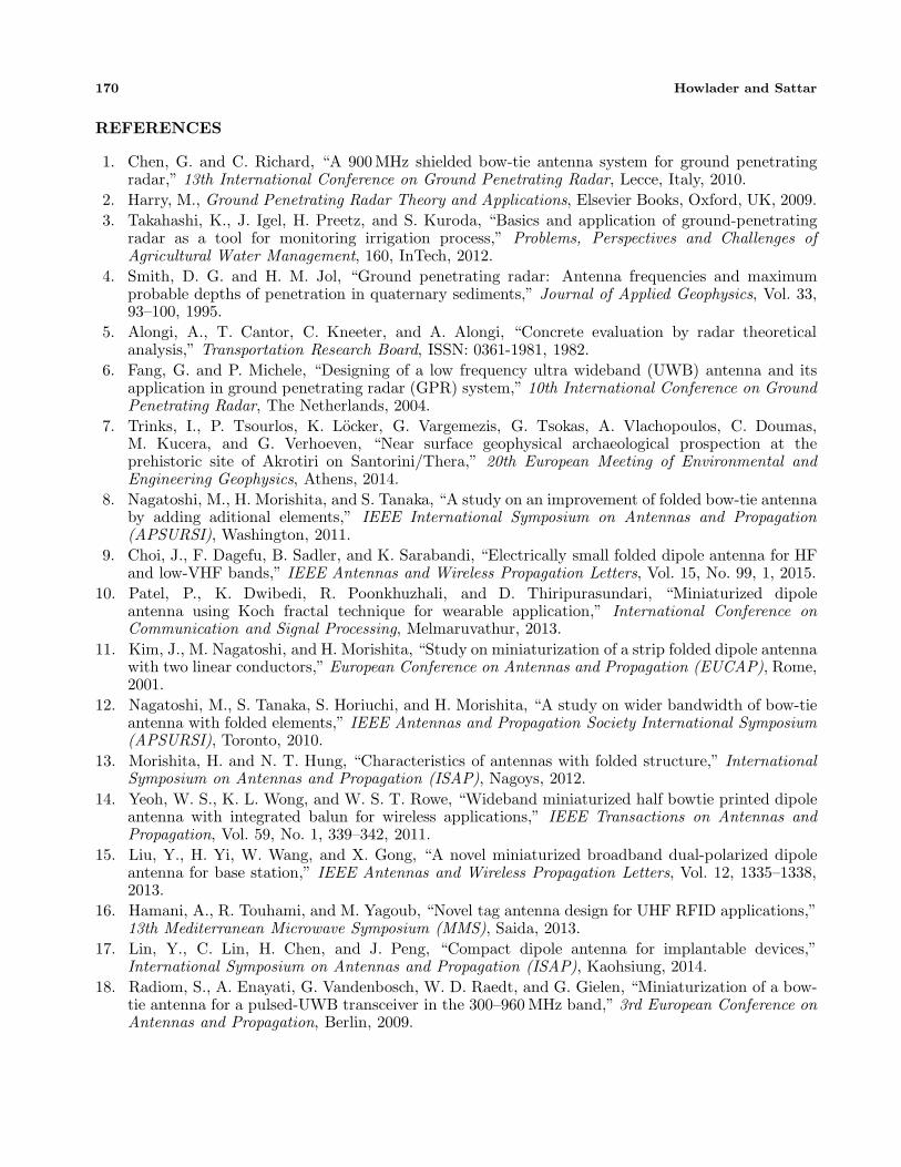
The radiation pattern in the E-plane and H-plane of the antenna in Figure 14 demonstrates that theproposed antenna has a typical dipole-like characteristics at the resonant frequency band. The patternsare nearly omnidirectional with an efficiency value of 71%. In this condition, the directivity gain is2.06 dBi compared to 2.15 dBi for more conventional dipoles. These values are considered as good inthe literature.
Figure 14. Radiation pattern of the proposed antenna at 102 MHz centre frequency.
168 Howlader and Sattar
5. EXPERIMENTAL VALIDATION
To validate the simulation results and antenna performance, a prototype antenna with extra radiatingarms was fabricated using a 1.6 mm thick FR4 dielectric substrate (εr = 4.4, tan d = 0.02). The antennaarms were printed on the substrate using 17 µm thick copper strips. The whole length of the antennawas 665 mm, and width was 220 mm. Figure 15 shows the fabricated prototype antenna with all thedimensions and fed by a 50 Ω BNC connector.
To measure the antenna performance, an Agilent 4395A network analyser was used. This particularanalyser can provide 10 Hz–500 MHz sweep frequency capability. Figure 15 shows the reflectioncoefficient graph of the antenna under test at 75–125 MHz frequency sweep with centre frequency at104 MHz. However, the used network analyser does not support digital screen capture facility. Therefore,the test was carried out for the full 500 MHz frequency sweep, and the raw data were saved as comma-separated values (csv) format and regenerated using Matlab which is shown in Figure 16 along with theradiation pattern graph.
Experiments show that the proposed antenna resonates at centre frequency of 104 MHz comparedto 100.5 MHz obtained by FEKO simulation. The measured reflection coefficient value is −15.88 dB,which is fairly in line with the value of −15.2 dB obtained during simulation. Measured radiationpattern graph shows an expected omnidirectional radiation at 1.52 dBi of directional gain with 68%efficiency compared to 2.01 dBi resulted in simulation. Also, judging from the Figure 17, the fabricatedantenna delivers a bandwidth of 8 MHz where VSWR ≤ 2 compared to 9.5 MHz bandwidth obtainedfrom simulation. This is a reduction of only 2 MHz compared to a conventional dipole antenna. Acomparison of the proposed antenna with a conventional dipole and other miniaturization techniquesfound in the literature is presented in Table 2.
Figure 15. Prototype antenna and antenna testing using Agilent 4395A network analyser.
Figure 16. Measured S11 of the proposed antenna along with the radiation pattern.
Progress In Electromagnetics Research C, Vol. 61, 2016 169
Figure 17. VSWR characteristic comparison of measured and simulated values.
Table 2. Comparison summary.
Antennatype
Centrefrequency (MHz)
Bandwidth(MHz)
Antennasize (cm)
Efficiency Remark
Dipole 100 10 150 × 1 - -
This work 100 8 66.5 × 22 68%55% reduction
in length
[6] 1500 2700 32 × 240 68%31% reduction
in length
[18] 500 600 23 × 10 75%46% reduction
in length
6. CONCLUSION
In this paper, techniques of adding extra radiating arms to the conventional dipole antenna in orderto miniaturize its length have been presented. Parametric studies of the design parameters show thatadding three extra radiating arms to each primary dipole arm can help the antenna to resonate at alower frequency. Experiments show that antenna with 150 mm long extra arms, placed at 50 mm gapbetween themselves can operate at 104 MHz frequency. Simulated and experimental results are in goodagreement. There were some contrast in simulation results at frequency region over 300 MHz betweenADS and FEKO simulation suite. However, experimental results confirm the validity of results fromFEKO with close match. Nonetheless, a conventional dipole antenna operating at the same frequencylevel requires a dipole length of 150 cm, whereas, antenna proposed in this paper can achieve the sameresonance level at 66.5 cm length. Therefore, a reduction of 55% can be achieved by the techniquespresented in this paper. Moreover, the operating bandwidth of the antenna is 99–107 MHz which isin line with a dipole antenna. Although there is an increase of 20 cm in terms of width, however, byimplementing this technique the length of a dipole could be halved. This feature will especially appealto low frequency GPR applications where used antennas are relatively long in dimension. The proposedantenna can be printed on an FR4 substrate which offers quick and inexpensive fabrication process. Allin all, the proposed miniaturized dipole antenna can offer lightweight, simple and great portability forlow frequency GPR systems. Future works of this research involve incorporating GPR pulse generatorwith the fabricated antenna for the detection of buried objects in various media.
170 Howlader and Sattar
REFERENCES
1. Chen, G. and C. Richard, “A 900 MHz shielded bow-tie antenna system for ground penetratingradar,” 13th International Conference on Ground Penetrating Radar, Lecce, Italy, 2010.
2. Harry, M., Ground Penetrating Radar Theory and Applications, Elsevier Books, Oxford, UK, 2009.3. Takahashi, K., J. Igel, H. Preetz, and S. Kuroda, “Basics and application of ground-penetrating
radar as a tool for monitoring irrigation process,” Problems, Perspectives and Challenges ofAgricultural Water Management, 160, InTech, 2012.
4. Smith, D. G. and H. M. Jol, “Ground penetrating radar: Antenna frequencies and maximumprobable depths of penetration in quaternary sediments,” Journal of Applied Geophysics, Vol. 33,93–100, 1995.
5. Alongi, A., T. Cantor, C. Kneeter, and A. Alongi, “Concrete evaluation by radar theoreticalanalysis,” Transportation Research Board, ISSN: 0361-1981, 1982.
6. Fang, G. and P. Michele, “Designing of a low frequency ultra wideband (UWB) antenna and itsapplication in ground penetrating radar (GPR) system,” 10th International Conference on GroundPenetrating Radar, The Netherlands, 2004.
7. Trinks, I., P. Tsourlos, K. Locker, G. Vargemezis, G. Tsokas, A. Vlachopoulos, C. Doumas,M. Kucera, and G. Verhoeven, “Near surface geophysical archaeological prospection at theprehistoric site of Akrotiri on Santorini/Thera,” 20th European Meeting of Environmental andEngineering Geophysics, Athens, 2014.
8. Nagatoshi, M., H. Morishita, and S. Tanaka, “A study on an improvement of folded bow-tie antennaby adding aditional elements,” IEEE International Symposium on Antennas and Propagation(APSURSI), Washington, 2011.
9. Choi, J., F. Dagefu, B. Sadler, and K. Sarabandi, “Electrically small folded dipole antenna for HFand low-VHF bands,” IEEE Antennas and Wireless Propagation Letters, Vol. 15, No. 99, 1, 2015.
10. Patel, P., K. Dwibedi, R. Poonkhuzhali, and D. Thiripurasundari, “Miniaturized dipoleantenna using Koch fractal technique for wearable application,” International Conference onCommunication and Signal Processing, Melmaruvathur, 2013.
11. Kim, J., M. Nagatoshi, and H. Morishita, “Study on miniaturization of a strip folded dipole antennawith two linear conductors,” European Conference on Antennas and Propagation (EUCAP), Rome,2001.
12. Nagatoshi, M., S. Tanaka, S. Horiuchi, and H. Morishita, “A study on wider bandwidth of bow-tieantenna with folded elements,” IEEE Antennas and Propagation Society International Symposium(APSURSI), Toronto, 2010.
13. Morishita, H. and N. T. Hung, “Characteristics of antennas with folded structure,” InternationalSymposium on Antennas and Propagation (ISAP), Nagoys, 2012.
14. Yeoh, W. S., K. L. Wong, and W. S. T. Rowe, “Wideband miniaturized half bowtie printed dipoleantenna with integrated balun for wireless applications,” IEEE Transactions on Antennas andPropagation, Vol. 59, No. 1, 339–342, 2011.
15. Liu, Y., H. Yi, W. Wang, and X. Gong, “A novel miniaturized broadband dual-polarized dipoleantenna for base station,” IEEE Antennas and Wireless Propagation Letters, Vol. 12, 1335–1338,2013.
16. Hamani, A., R. Touhami, and M. Yagoub, “Novel tag antenna design for UHF RFID applications,”13th Mediterranean Microwave Symposium (MMS), Saida, 2013.
17. Lin, Y., C. Lin, H. Chen, and J. Peng, “Compact dipole antenna for implantable devices,”International Symposium on Antennas and Propagation (ISAP), Kaohsiung, 2014.
18. Radiom, S., A. Enayati, G. Vandenbosch, W. D. Raedt, and G. Gielen, “Miniaturization of a bow-tie antenna for a pulsed-UWB transceiver in the 300–960 MHz band,” 3rd European Conference onAntennas and Propagation, Berlin, 2009.