Minimizing Network Complexity through Integrated Top-Down Design Xin Sun School of Computing and Information Sciences Florida International University xinsun@cs.fiu.edu Geoffrey G. Xie Department of Computer Science Naval Postgraduate School [email protected]ABSTRACT The network design process today remains ad-hoc and largely com- plexity agnostic, often resulting in suboptimal networks charac- terized by excessive amounts of dependencies and commands in device configurations. The unnecessarily high configuration com- plexity can lead to a huge increase in both the amount of manual intervention required for managing the network and the likelihood of configuration errors, and thus must be avoided. In this paper we present an integrated top-down design approach and show how it can minimize the unnecessary configuration complexity in re- alizing user reachability control, a key network design objective that involves designing three distinct network elements: VLAN, IP address, and packet filter. Capitalizing on newly-developed ab- stractions, our approach integrates the design of the three elements into a unified framework by systematically modeling how the de- sign of one element may impact the complexity of other elements. Our approach goes substantially beyond the current “divide-and- conquer” approach that designs each element in complete isolation, and enables minimizing the combined complexity of all elements. Specifically, two new optimization problems are formulated, and novel algorithms and heuristics are developed to solve the formu- lated problems. Evaluation on a large campus network shows that our approach can effectively reduce the packet filter complexity and VLAN trunking complexity by more than 85% and 70%, respec- tively, when compared to the ad-hoc approach currently used by the operators. Categories and Subject Descriptors C.2.3 [Computer-Communication Networks]: Network Opera- tions—Network management Keywords Network complexity; Top-down design; Reachability control; VLAN; IP address allocation 1 Introduction Recent research [7,22,31] and vendor documents [1,27] reveal that multiple, distinct routing designs are possible to meet the same set Permission to make digital or hard copies of all or part of this work for personal or classroom use is granted without fee provided that copies are not made or distributed for profit or commercial advantage and that copies bear this notice and the full citation on the first page. Copyrights for components of this work owned by others than the author(s) must be honored. Abstracting with credit is permitted. To copy otherwise, or republish, to post on servers or to redistribute to lists, requires prior specific permission and/or a fee. Request permissions from [email protected]. CoNEXT’13, December 9–12, 2013, Santa Barbara, California, USA. Copyright is held by the owner/author(s). Publication rights licensed to ACM. ACM 978-1-4503-2101-3/13/12 ...$15.00. http://dx.doi.org/10.1145/2535372.2535376. of enterprise network operational requirements (e.g., security pol- icy represented by a reachability matrix [35]). Moreover, the con- figuration complexity of these designs can vary greatly. In other words, some designs may incur much higher configuration com- plexity than others while accomplishing the same objectives. The unnecessarily high configuration complexity is highly undesirable as it can lead to a huge increase in both the amount of manual in- tervention required for managing the network and the likelihood of configuration errors. For example, a research report [20] discloses that 80% of enterprise IT budget is devoted to maintaining the sta- tus quo. Despite this investment, configuration errors account for 50-80% of network outages [18, 20] and enable 65% of all suc- cessful cyber-attacks [28]. There is a general perception that com- plexity is the primary cause of high human costs, and interviews and anecdotal evidence suggest that an operator’s ability to run a network decreases as the network becomes more complex [7]. Thus, an important open research question arises: Is it possible to systematically identify, among all designs that can meet given operational requirements, the one(s) with the minimum amount of configuration complexity? The current state of network design practice by operators is mostly ad hoc and, in particular, does not rigorously formulate the goal of minimizing network complexity. As a result, a large number of existing production networks may not be optimal in terms of con- figuration complexity [22, 33], likely causing a huge increase in operational costs. Having recognized the importance of the prob- lem and associated challenges, researchers have recently begun to investigate this problem in the specific context of enterprise net- work design [32, 33]. These approaches focus primarily on meet- ing the specific objective of user reachability control (essentially implementing a subnet-level reachability matrix). They enable an operator to formulate an individual design task, such as grouping hosts of his/her network into different VLANs, into a model of opti- mizing a desired performance metric subject to a set of correctness and feasibility constraints. While these recent advances in systematic network design cre- ate a major opportunity to address the complexity problem, the current approaches suffer from a critical limitation: they employ a “divide-and-conquer” (i.e., stage-by-stage) strategy that simply models individual design steps in complete isolation even when the steps together implement a common goal. For example, totally in- dependent formulations and optimality criteria are used for VLAN design and packet filter design [33] even though the two design steps share a common objective of user reachability control. While these formulations can potentially minimize the complexity of con- figuration at each design stage in isolation, the overall complexity may still be unnecessarily high. This is because the design choices made at an early stage (e.g., VLAN design or IP address allocation) 1
The network design process today remains ad-hoc and largely com-plexity agnostic, often resulting in suboptimal networks charac-terized by excessive amounts of dependencies and commands indevice configurations. The unnecessarily high configuration com-plexity can lead to a huge increase in both the amount of manualintervention required for managing the network and the likelihoodof configuration errors, and thus must be avoided. In this paperwe present an integrated top-down design approach and show howit can minimize the unnecessary configuration complexity in re-alizing user reachability control, a key network design objectivethat involves designing three distinct network elements: VLAN,IP address, and packet filter. Capitalizing on newly-developed ab-stractions, our approach integrates the design of the three elementsinto a unified framework by systematically modeling how the de-sign of one element may impact the complexity of other elements.Our approach goes substantially beyond the current “divide-and-conquer” approach that designs each element in complete isolation,and enables minimizing the combined complexity of all elements.Specifically, two new optimization problems are formulated, andnovel algorithms and heuristics are developed to solve the formu-lated problems. Evaluation on a large campus network shows thatour approach can effectively reduce the packet filter complexity andVLAN trunking complexity by more than 85% and 70%, respec-tively, when compared to the ad-hoc approach currently used bythe operators.
CoNEXT’13, December 9–12, 2013, Santa Barbara, California, USA.
Copyright is held by the owner/author(s). Publication rights licensed to ACM.
ACM 978-1-4503-2101-3/13/12 ...$15.00.
http://dx.doi.org/10.1145/2535372.2535376.
of enterprise network operational requirements (e.g., security pol-icy represented by a reachability matrix [35]). Moreover, the con-figuration complexity of these designs can vary greatly. In otherwords, some designs may incur much higher configuration com-plexity than others while accomplishing the same objectives. Theunnecessarily high configuration complexity is highly undesirableas it can lead to a huge increase in both the amount of manual in-tervention required for managing the network and the likelihood ofconfiguration errors. For example, a research report [20] disclosesthat 80% of enterprise IT budget is devoted to maintaining the sta-tus quo. Despite this investment, configuration errors account for50-80% of network outages [18, 20] and enable 65% of all suc-cessful cyber-attacks [28]. There is a general perception that com-plexity is the primary cause of high human costs, and interviewsand anecdotal evidence suggest that an operator’s ability to run anetwork decreases as the network becomes more complex [7].
Thus, an important open research question arises: Is it possible
to systematically identify, among all designs that can meet given
operational requirements, the one(s) with the minimum amount of
configuration complexity?
The current state of network design practice by operators is mostlyad hoc and, in particular, does not rigorously formulate the goal ofminimizing network complexity. As a result, a large number ofexisting production networks may not be optimal in terms of con-figuration complexity [22, 33], likely causing a huge increase inoperational costs. Having recognized the importance of the prob-lem and associated challenges, researchers have recently begun toinvestigate this problem in the specific context of enterprise net-work design [32, 33]. These approaches focus primarily on meet-ing the specific objective of user reachability control (essentiallyimplementing a subnet-level reachability matrix). They enable anoperator to formulate an individual design task, such as groupinghosts of his/her network into different VLANs, into a model of opti-mizing a desired performance metric subject to a set of correctnessand feasibility constraints.
While these recent advances in systematic network design cre-ate a major opportunity to address the complexity problem, thecurrent approaches suffer from a critical limitation: they employa “divide-and-conquer” (i.e., stage-by-stage) strategy that simplymodels individual design steps in complete isolation even when thesteps together implement a common goal. For example, totally in-dependent formulations and optimality criteria are used for VLANdesign and packet filter design [33] even though the two designsteps share a common objective of user reachability control. Whilethese formulations can potentially minimize the complexity of con-figuration at each design stage in isolation, the overall complexitymay still be unnecessarily high. This is because the design choicesmade at an early stage (e.g., VLAN design or IP address allocation)
1
can significantly impact the available design space of a later stage(e.g., packet filters), potentially resulting in a substantial amount ofunnecessary complexity.
We observe that in practice, in addition to reachability control,many other common and important operational objectives are alsoachieved through designing multiple networking elements at differ-ent stages. Two prominent examples are (i) quality of service (QoS)which involves end-to-end traffic engineering, source policing, andper link bandwidth management; and (ii) resiliency which requiresplanning of both physical and logical topologies. For these impor-tant objectives, the current “divide-and-conquer” design approachis incapable of eliminating all the unnecessary complexity.
In this paper, we investigate a novel integrated top-down method-ology that jointly designs multiple networking elements involvedin achieving a common objective. The key components of our ap-proach include: (i) for a given design objective, identifying all thenetworking elements that may be involved in its implementation,and their interactions (i.e., how the design of one element couldaffect the design of others); (ii) characterizing the source of com-plexity in each element, leveraging recently-developed complexitymetrics; (iii) formulating the design problem as one of minimizingthe total complexity of all involved elements, subject to correct-ness and feasibility constraints; and (iv) developing specific algo-rithms and heuristics to solve the formulated problems. As such,this new approach goes substantially beyond the state-of-the-art“divide-and-conquer” approaches. It requires not only entirely newformulations and algorithms, but also fundamentally new abstrac-tions and models in order to integrate multiple design steps into aunified framework.
Our integrated design methodology is general and can be appliedto a variety of network design objectives and scenarios. In order todemonstrate its feasibility and power at sufficient depths, in this pa-per we focus on one concrete application of the methodology: userreachability control. We choose reachability control because (i)security is of vital importance to virtually every enterprise network,and (ii) the design involves at least three networking elements, andas such it is both highly challenging and at the same time may ben-efit greatly from the new approach.
Similarly, while our approach is agnostic to the type of networkcomplexity metric used1, the focus of this paper is on minimizingthe configuration complexity, specifically the amount of command
dependencies [7] in the router configurations of the resulting net-work. According to recent studies [7, 31, 32], these dependenciesare directly linked to the operational cost as they require substan-tial manual effort to configure correctly in the initial implemen-tation and manage in subsequent evolutions, and if not maintainedproperly, can lead to serious issues such as application performancedegradation and security breaches.
We evaluate the benefits of the new approach in the context ofthe heuristics we have developed for solving the formulated designproblem of user reachability control. The evaluation is conductedon a large university campus network with a few thousand userhosts. The results show that our approach can effectively reducethe number of packet filter rules and the number of VLAN trunkports by more than 85% and 70%, respectively, when compared tothe ad-hoc approach currently used by the operators.
The rest of the paper is organized as follows. In Section 2, webriefly survey the state of the art. In Section 3, we first substan-tiate the need for the integrated design approach using a detailedexample of reachability control design. We then demonstrate howthe integrated approach can be applied to reachability control, and
1Section 7 provides a brief discussion of other potential complexitymetrics.
formally introduce an integrated design framework for this prob-lem. In Sections 4 and 5, we present new formulations and novelheuristics to accomplish the two design problems identified by theframework: joint design of VLAN and packet filter, and joint de-sign of IP allocation and packet filter. Section 6 describes a throughevaluation of our heuristics in a large campus network setting. Pos-sible extensions and open issues are discussed in Section 7. Finally,we conclude the paper and briefly outline our plan for future workin Section 8.
2 State of Art of Network Design
In this section, we overview the current state of the art of enter-prise network design, specifically focusing on the more recent de-velopments in top-down design techniques. Our aim is to not onlydiscuss related work, but also provide a historical perspective ofthe proposed integrated design approach before we present detailedexamples to substantiate how the new approach may reduce com-plexity in the next section.
2.1 Operational Practice and Tools
The operational community has a rich history of crafting the artof network design and reconfiguration. Nonetheless, the state ofthe practice by operators is still defined predominantly by ad-hoc,manual decision making. Notable efforts to simplifying networkdesign involve template-based approaches that codify and promotebest practices [1, 2, 3, 4] and abstract languages to specify configu-rations in a vendor-neutral fashion [12]. There are also tools suchas PRESTO [13] to convert a network design into device-vendor-specific configuration commands. These approaches merely modelthe low-level mechanisms and their configuration. They do notmodel network-wide operator intent such as reachability and man-ageability. A logic-based approach to configuration generation basedon model-finding is presented in [25]. The focus is on the gener-ation of configuration parameters conforming to correctness rulesdistilled from best practices, and the system does not take complex-ity into consideration. Many works have approached the problemof minimizing the number of rules in a single access control list(ACL) (e.g., [23]). In contrast, we focus on minimizing the totalnumber of packet filter rules required for a given network to meetall its reachability control requirements.
Finally, various design guidelines including those for a top-downnetwork design approach [27] can be found in the literature. Theseguidelines provide practical insights into the trade-offs of differentdesign choices regarding topology, hardware and protocols. How-ever, considerable manual effort is required to determine how toapply these guidelines to the design of a network of medium tolarge size.
2.2 Systematic Multi-Stage Design
Systematic network design, characterized by the use of a formalmodel to generate configuration that is provably correct and ad-ditionally optimizes certain performance metrics, has emerged asa potential solution to the challenges facing the operational com-munity. Early efforts on this front focus on tasks encountered incarrier networks, such as configuring BGP policies [9, 14, 16, 17],optimizing OSPF weights [29], and redundancy planning.
More recent studies [32, 33] target enterprise networks specif-ically. They employ a “divide-and-conquer” strategy and performnetwork design in a stage-by-stage fashion, e.g., effectively treatingVLAN design and packet filter design as two completely indepen-dent tasks. While these studies have advanced the state of the art ofsystematic network design, their models may produce designs withunnecessarily high configuration complexity, as we will elaborate
2
in Section 3. It is this unnecessary complexity that this work seeksto expose and minimize.
It should be noted that the recent progress in systematic networkdesign owes largely to new abstractions from related work in sev-eral areas, including (i) characterization of the designs of produc-tion networks (e.g., [22]), (ii) static analysis of network properties(e.g., [21, 35]), and (iii) the formulation of new configuration com-plexity metrics [7].
2.3 Software Defined Networking
To combat network complexity, researchers have started investigat-ing new software-defined networking (SDN) architectures based onlogically centralized controllers and declarative configuration lan-guages (e.g., Frenetic [15]). These approaches have the potentialto simplify network design by shifting complexity away from con-figuration of many individual devices to programming of few cen-tralized controllers. While SDN has shown potential, challengingproblems such as the need to update network devices in a consistentfashion [30] must be resolved before it can be widely deployed.
More importantly, SDN operators must carry out a similar de-sign task of translating high-level reachability control requirementsinto flow rules. Since these flow rules will be installed on demandin the Ternary Content Addressable Memory (TCAM) of switchesand once installed, checked for each packet passing through, it isdesirable to minimize the number of such rules required. In thisway, the design methodology and heuristics presented in this paperalso apply to an SDN setting, as further discussed in Section 7.
3 An Integrated Design Framework for
Reachability Control
We now apply the integrated top-down approach as described inSection 1 to the user reachability control problem. With an illus-trative example scenario, we identify the networking elements thatare involved in realizing this important design objective, understandthe source of configuration complexity of each element, and cap-ture how the designs of individual elements may interact with eachother and impact the overall complexity. We then present a frame-work for achieving an integrated design of user readability control.
3.1 An Illustrative Example Scenario
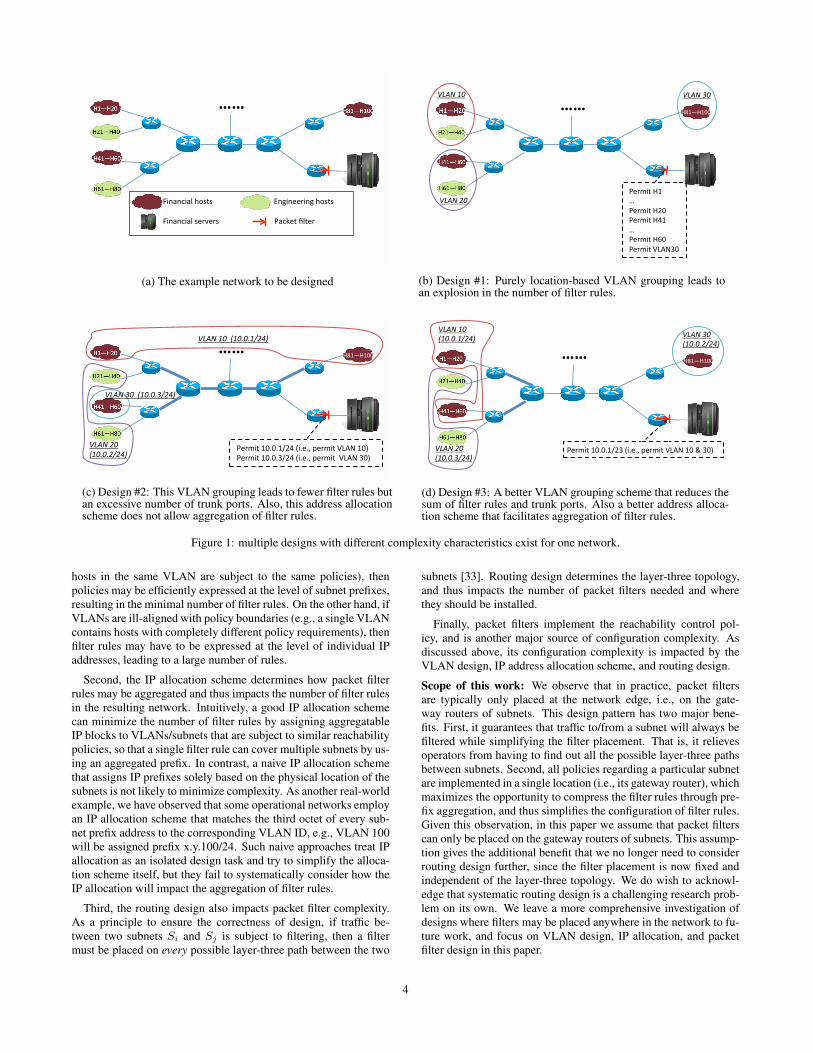
Our example is based on the toy network shown in Fig. 1a. Thereare two departments: Engineering and Financial. Each departmenthas users in multiple locations as shown. In addition, there is aset of servers. The reachability control policy is that the serversshould only be accessed by Financial users. The following designsteps are needed to implement the policy: (i) grouping the hostsinto VLANs; (ii) assigning subnet addresses to VLANs; and (iii)installing a filter restricting access to the servers. We are given thefollowing design constraints: at most three VLANs can be created;and the available IP blocks are 10.0.1/24, 10.0.2/24 and 10.0.3/24.
Fig. 1b illustrates a first possible design, where hosts are groupedinto VLANs solely based on their physical locations. Unfortu-nately, this grouping scheme makes configuring the filter difficult:it is not possible to express the rules at the level of subnet pre-fixes for VLAN 10 or VLAN 20, because they both contain hostsfrom both departments. As such, we have to write filter rules at thelevel of IPs to permit individual Financial hosts, which results inan explosive growth of rules. We note that each packet filter is asequential collection of filter rules, and each filter rule contains apattern to be matched against packet headers, and an action (i.e.,permit or deny) to be applied to packets whose header matches thecorresponding pattern. The pattern part may be configured to matchspecific values of all or any subset of the five header fields: source
and destination IPs and ports, and protocol; and thus creates staticdependencies on those filed values. Such dependencies must bemanually configured and maintained and thus are a major source ofconfiguration complexity.
Fig. 1c depicts a different design, where hosts in the same VLANbelong to the same department. This design enables expressing fil-ter rules at the level of subnet prefixes, which significantly reducesthe number of rules and thus simplifies the filter configuration.However, this design suffers from a different kind of configurationcomplexity: it requires configuring a large number of VLAN trunk
ports, as denoted by the bold lines in the figure. Trunk ports arethe switch ports that connect to another switch. Since each VLANconstitutes a separate broadcast domain, it is important to properlyconstrain broadcast traffic to eliminate unnecessary broadcast traf-fic for increased performance and security. More specifically, ev-ery switch-to-switch link (called “trunk link”) must be configuredto only allow traffic of appropriate VLANs. This is achieved bymanually configuring the corresponding trunk ports to permit thosespecific VLANs. VLAN trunk ports configuration is widely con-sidered a major source of complexity, as operators must manuallyidentify and configure the correct set of VLANs to allow for eachport. (Readers are referred to Sec.II-A of [32] for a more detailedexplanation of trunk ports).
Fig. 1d shows a third design. The design still enables expressingfilter rules at the subnet prefix level, but also significantly reducesthe amount of trunk port configuration by requiring fewer VLANtrunk ports. Furthermore, the IP allocation scheme of this designis better than the previous one as it facilitates prefix aggregationwhen expressing rules, i.e., it allows aggregating the two originalfilter rules (“permit 10.0.1/24” and “permit 10.0.2/24”) into a single/23 rule (“permit 10.0.1/23”) as shown.
We make two observations from this example. First, for the sametarget network, there exist multiple designs that are all correct. Forour example network, there are at least 6 different designs (threedifferent VLAN grouping schemes coupled with two different ad-dress allocation schemes.) However, different designs have differ-ent levels of configuration complexity. Second, the complexity ofthe resulting network is determined by both the VLAN configura-tion complexity (characterized by the number of trunk ports) andthe packet filter complexity (characterized by the number of filterrules). Furthermore, the packet filter design is directly impactedby both the VLAN grouping scheme and the IP address allocationscheme. Thus, a design approach clearly will not work well if ittreats VLAN grouping and IP allocation as total independent tasksand ignore their inherent interactions. For example, current top-down design approaches (e.g., [32, 33]) consider VLAN design asan isolated task, and thus they will solely seek to minimize the num-ber of trunk ports without considering how doing so will impactthe packet filter design, i.e., they will pick the first design shown inFig. 1b for our toy example, which is clearly not the best.
3.2 Elements of Reachability Control and Their Interactions
Realizing a host-level reachability control consists of designingthe following networking elements: VLAN, IP address allocation,routing, and packet filters. We discuss below the role of each ofthese elements, their impact on configuration complexity, and theirinherent interactions.
First, the VLAN design directly determines the number of trunkports that need to be configured and maintained in the resulting net-work, a major source of operational complexity. Furthermore, theVLAN design also significantly impacts the packet filter complex-ity, as it determines how hosts are grouped into subnets. Intuitively,if the VLANs align well with reachability policy boundaries (e.g.,
(b) Design #1: Purely location-based VLAN grouping leads toan explosion in the number of filter rules.
!!""!
!"#$%&'()*)*(+,-'.%*"*/'0"#$%&'1234'()5'
!"#$%&'()*)*6+,-'.%*"*/'0"#$%&''1234'6)5'
!"#$%&'%%(&')')&*+,-%
!"#$%+'%
(&')')+*+,-%
7,(87-)'
79(87:)'
7(87,)'
7-(879)'
7:(87())'
!"#$%.'%%(&')').*+,-%
(c) Design #2: This VLAN grouping leads to fewer filter rules butan excessive number of trunk ports. Also, this address allocationscheme does not allow aggregation of filter rules.
(d) Design #3: A better VLAN grouping scheme that reduces thesum of filter rules and trunk ports. Also a better address alloca-tion scheme that facilitates aggregation of filter rules.
Figure 1: multiple designs with different complexity characteristics exist for one network.
hosts in the same VLAN are subject to the same policies), thenpolicies may be efficiently expressed at the level of subnet prefixes,resulting in the minimal number of filter rules. On the other hand, ifVLANs are ill-aligned with policy boundaries (e.g., a single VLANcontains hosts with completely different policy requirements), thenfilter rules may have to be expressed at the level of individual IPaddresses, leading to a large number of rules.
Second, the IP allocation scheme determines how packet filterrules may be aggregated and thus impacts the number of filter rulesin the resulting network. Intuitively, a good IP allocation schemecan minimize the number of filter rules by assigning aggregatableIP blocks to VLANs/subnets that are subject to similar reachabilitypolicies, so that a single filter rule can cover multiple subnets by us-ing an aggregated prefix. In contrast, a naive IP allocation schemethat assigns IP prefixes solely based on the physical location of thesubnets is not likely to minimize complexity. As another real-worldexample, we have observed that some operational networks employan IP allocation scheme that matches the third octet of every sub-net prefix address to the corresponding VLAN ID, e.g., VLAN 100will be assigned prefix x.y.100/24. Such naive approaches treat IPallocation as an isolated design task and try to simplify the alloca-tion scheme itself, but they fail to systematically consider how theIP allocation will impact the aggregation of filter rules.
Third, the routing design also impacts packet filter complexity.As a principle to ensure the correctness of design, if traffic be-tween two subnets Si and Sj is subject to filtering, then a filtermust be placed on every possible layer-three path between the two
subnets [33]. Routing design determines the layer-three topology,and thus impacts the number of packet filters needed and wherethey should be installed.
Finally, packet filters implement the reachability control pol-icy, and is another major source of configuration complexity. Asdiscussed above, its configuration complexity is impacted by theVLAN design, IP address allocation scheme, and routing design.
Scope of this work: We observe that in practice, packet filtersare typically only placed at the network edge, i.e., on the gate-way routers of subnets. This design pattern has two major bene-fits. First, it guarantees that traffic to/from a subnet will always befiltered while simplifying the filter placement. That is, it relievesoperators from having to find out all the possible layer-three pathsbetween subnets. Second, all policies regarding a particular subnetare implemented in a single location (i.e., its gateway router), whichmaximizes the opportunity to compress the filter rules through pre-fix aggregation, and thus simplifies the configuration of filter rules.Given this observation, in this paper we assume that packet filterscan only be placed on the gateway routers of subnets. This assump-tion gives the additional benefit that we no longer need to considerrouting design further, since the filter placement is now fixed andindependent of the layer-three topology. We do wish to acknowl-edge that systematic routing design is a challenging research prob-lem on its own. We leave a more comprehensive investigation ofdesigns where filters may be placed anywhere in the network to fu-ture work, and focus on VLAN design, IP allocation, and packetfilter design in this paper.
4
3.3 Formulating the Reachability Control Design Problem
Following the integrated design methodology described in Section 1,we now present a design framework for reachability control, whichintegrates the design of the individual elements identified above. Indoing so, our goal is to enable the design process to be fully au-tomated, and require only high-level specifications from operators.We first present a new abstraction that facilitates specifying andmodeling reachability policy, and then present the framework.
3.3.1 A New Abstraction for Specifying Reachability Policies
An essential input to our framework is the reachability control poli-cies, and it is important to consider how they should be specified.The current “divide-and-conquer” design approach [33] requiresreachability policies to be specified at the VLAN/subnet level, i.e.,it requires operators to specify a reachability matrix where eachcell (i, j) denotes the reachability between VLAN i and VLANj. This abstraction works for the “divide-and-conquer” approachwhich assumes that the VLAN design has already been completedbefore designing packet filters. However, it does not work for ourapproach which integrates the design of VLANs and packet filters,i.e., our framework cannot use such a VLAN-level reachability ma-trix as input because VLANs themselves are to be determined bythe solution. In addition, we believe that the VLAN-level reacha-bility matrix is too low level as a policy abstraction, and it is tediousfor operators to specify reachability policy using it.
In this work, we introduce a new abstraction for specifying reach-ability policy: a reachability matrix at “user role” level. We definea user role as a logical category that a set of users or servers belongto. Example user roles include faculty users, Computer Scienceusers, financial servers, etc. Note that a user may have multipleroles, e.g., a CS professor can have both roles of CS users andfaculty users. Each cell (i, j) of the reachability matrix specifiesreachability policy between a user role i and another user role j.The advantage of this abstraction is that it allows policies to bespecified at a high level and independent of any design details.
3.3.2 Formulating Reachability Control Design
We formulate the design problem of reachability control as follows.We assume we are given the physical topology of the network,and the set of users/servers and their network locations. For eachuser/server, we are given its user roles. We are given the reacha-bility matrix at the user-role level as described above. In addition,we are given the maximum number of VLANs that can be created(denoted by N ), and the available IP blocks. The design frame-work includes tasks of (i) mapping the set of users to at most NVLANs, (ii) assigning IP blocks from the available IP space to thecreated VLANs, and (iii) configuring packet filters to enforce thereachability policies. Our goal is to minimize the total configura-tion complexity of the resulting network. As discussed above, theconfiguration complexity (denoted as Ctotal ) includes both VLAN-related complexity (denoted by Cv), measured by the number oftrunk ports, and filter-related complexity (denoted by Cf ), mea-sured by the number of filter rules. Formally, we model the totalconfiguration complexity as:
Ctotal = Wv ∗ Cv +Wf ∗ Cf (1)
where Wv and Wf are the weight factors given to the two complex-ity categories, and can be customized by operators. For example, ifthe operators of a network consider VLAN trunk ports more diffi-cult to configure and maintain than filter rules, they can assign Wv
a higher value than Wf .
We notice that, while the VLAN grouping scheme and the IP al-location scheme both impact the packet filter complexity, VLAN
design and IP allocation scheme are completely independent ofeach other, i.e., the design choices made in VLAN grouping won’taffect the available design space of the IP allocation scheme, andvice versa. Given this insight, we are able to formulate the design ofreachability control as two joint design problems in order to makeit more tractable:
• Joint design of VLANs and packet filters;
• Joint design of IP allocation scheme and packet filters.
The output of the first joint design includes the VLAN groupingscheme, and an intermediate representation of packet filter rules ex-pressed in terms of individual VLANs and hosts. This intermediaterepresentation of packet filters then becomes part of the input to thesecond joint design. The output of the second joint design includesthe IP allocation scheme, and complete packet filters expressed interms of IP address blocks. In the next two sections, we formulateand solve the two joint design problems.
4 Joint Design of VLANs and Packet Filters
We first present models for formulating the joint design problem,and then develop heuristics for solving the formulated problem.
4.1 Formulating the Joint Design Problem
This design task is to map hosts to a set of VLANs and to de-rive packet filter rules expressed in terms of individual VLANs andhosts. There are several important considerations in doing so, aswe detail below.
VLAN count: The total number of VLANs that can be createdin the design is determined by the hardware used in the network.This is because each VLAN runs its own instance of spanning tree,which consumes the memory and CPU resource of the switches.For example, a Cisco Catalyst 2950 switch can only support upto 64 spanning tree instances [11]. To model this constraint, wesimply assume that operators will specify the maximum number ofVLANs that can be created, which is denoted by N .
VLAN size: A VLAN becomes a separate subnet at layer three,and thus the number of hosts that a VLAN can have is boundedby the size of the IP address block assigned to the correspondingsubnet (assuming NAT is not used). For example, it is a commonpractice to limit the maximum size of a VLAN to that of a /24subnet, i.e., at most 254 hosts. We assume the operators will specifythe maximum VLAN size, denoted by MAX-VLAN-SIZE.
Correctness criteria: To ensure the correctness of the design, thefollowing two conditions must be satisfied. First, the given reacha-bility policies must be correctly implemented through packet filters.Second, all hosts in the same VLAN must have full reachability to-ward each other, since they are all in the same broadcast domain.
Configuration complexity: This design will determine the VLANconfiguration complexity Cv (i.e., the total number of VLAN trunkports in the resulting network). Further, it will also impact thepacket filter configuration complexity. Note that the filter rules gen-erated by this design are expressed in terms of individual VLANsand hosts. The VLANs and hosts will be assigned IP addresses inthe second joint design, and thus the filter rules could be furtheraggregated when converted to the IP representation in that design.Thus, we model the total configuration complexity introduced bythis design (denoted by C ′
total ) as follows:
C′
total = Wv ∗ Cv +Wf ∗ C′
f (2)
Wv , Wf and Cv have been defined for Equation (1). C ′
f is the con-figuration complexity of the packet filters generated by this designtask, measured as the total number of filter rules. Clearly C ′
f ≥ Cf
5
as the joint design of IP allocation and packet filters may furtherreduce the number of filter rules through prefix aggregation.
Now we can formally formulate this joint design problem as:
Minimize: C ′
total
Subject to:
- the correctness criteria, and- the constraints on VLAN number and size.
4.2 Heuristic for Solving the Joint Design Problem
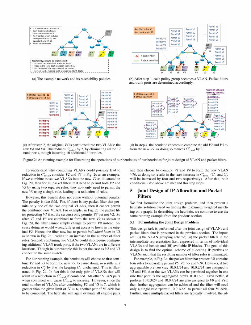
We present the details of our heuristic that works in a step-by-stepfashion. For ease of understanding, we use a running example toillustrate the various algorithmic operations. The example networksetup is shown in Fig. 2a. There are eight user roles: Biology,Computer Science, IT, Faculty, Students, managers, operators, andservers. The reachability policies are also shown in the graph. Weare given that N = 6, and MAX-VLAN-SIZE = 254. For simplic-ity, we assume that the operator has chosen to set Wv = Wf = 1.
4.2.1 Step 1: Map Policy Groups to VLANs
As illustrated in Section 3.1, it is often desirable for a VLAN tocontain hosts subject to the same reachability policy, because doingso enables filter rules to be written at the level of an entire VLAN.To capture this insight in the design process, we leverage the ab-straction of “policy groups” introduced by recent works [7, 31] in-cluding our own for network modeling. A policy group abstractsthe set of hosts that are (i) subject to the same reachability policy to-wards other hosts and (ii) have full reachability among themselves.Clearly the set of policy groups forms a partition of all hosts. It iseasy to see that a policy group is an atomic unit in deriving filterrules, i.e., if a packet filter allows traffic from one host in a pol-icy group, it must also allow traffic from all the other hosts of thesame policy group. Thus, the use of policy groups in the designprocess simplifies the reasoning of reachability control by allowingus to reason about groups of hosts together instead of individualones. We believe the set of policy groups can be straightforwardlyderived from the inputs of user roles and the role-level reachabilitymatrix, but omit the details due to lack of space.
As a reasonable starting point of the design, we initially let eachpolicy group become a separate VLAN. We then derive the filterrules. As mentioned in Sec.3.2, we have assumed that packet fil-ters can only be placed on the gateway routers of the VLANs to beprotected. Thus the filter rules can be determined in a straightfor-ward way: for each VLAN, the corresponding packet filter permitsall other VLANs (i.e., policy groups) that can communicate withthis VLAN, according to the reachability matrix. We assume animplicit deny in the end of a packet filter, following the vendorconvention. Filters that simply permit all traffic are omitted.
Fig. 2b illustrate the design after this step. Seven policy groupsare identified straightforwardly from the inputs: CS faculty (shownas CS-F on graph) which resides in two different locations, CS stu-dents (CS-S), Biology faculty (Bio-F), Biology students (Bio-S),IT managers (IT-M), IT operators (IT-O) and servers (SVR). Eachpolicy group has been placed in a separate VLAN. For example,the entire CS-Faculty policy group becomes VLAN V4. The corre-sponding VLAN trunk ports to be configured are shown by the boldlinks connecting those ports. The packet filters are also shown, andas expected all filter rules are expressed at the VLAN level. Finally,the amount of configuration complexity in terms of filter rules andtrunk ports after this step is also shown.
4.2.2 Step 2: Selectively Partition VLANs with Large Span
For each VLAN created in Step 1, we now evaluate whether it isbeneficial (i.e., leading to smaller C ′
total ) to partition it into two
smaller VLANs. If so, we will execute the partitioning, and iter-atively evaluate for the resulting two smaller VLANs. We repeatthis step for every VLAN until we cannot further reduce C ′
total bypartitioning existing VLANs. Our insight for this step is as follow.
On one hand, partitioning a VLAN that has a large span couldpotentially reduce C ′
total as it could significantly reduce the numberof trunk ports (i.e, Cv). Consider V4 (CS-Faculty policy group) inFig. 2b as an example. By partitioning it into two smaller VLANs,i.e., the new V4 and V8 in Fig. 2c, we eliminate the need for anytrunk port for this VLAN, and thus reduce Cv . On the other hand,partitioning a VLAN could also potentially increase C ′
total as itcould lead to more filters and/or filter rules required, i.e., an in-crease in C ′
f . There are two reasons for this. First, after the parti-tioning it may be necessary to install a new packet filter to protect anewly created VLAN. For example, in Fig. 2c there is a new packetfilter that protects the newly created V8, which introduces 6 newrules. Second, it may be necessary to add additional rules in theexisting filters, to permit a newly created VLAN. For example, inFig. 2c a rule “permit V8” is added to four existing filters.
More specifically, we employ the K-means clustering algorithm(with K=2) to decide how a VLAN should be partitioned into two,such that the reduction in Cv is maximized. In configuring the clus-tering algorithm, we let each host in the VLAN be a node, and thedistance between two nodes be the length of the shortest layer-twopath between the corresponding hosts. The clustering algorithmthen groups nearby hosts into the same VLAN and thus minimizesthe need of trunk ports.
For our running example, we find that by partitioning the oldVLAN V4 in Fig. 2b into two smaller VLANs V4 and V8 in fig.2c,we reduces Cv (i.e., the number of trunk ports) by 12, but in-creases C ′
f (i.e., the number of filter rules) by 10. As we assumeWv = Wf = 1, the total complexity is reduced by 2, according toEquation (2). Hence, we execute the partitioning since it is benefi-cial to do so. We also find that it is not beneficial to partition anyother VLAN. Fig. 2c shows the resulting design after this step.
4.2.3 Step 3: Partition VLANs with Too Many Hosts
This step ensures that the constraint on VLAN size is met. It checkseach VLAN in the current design to see whether it contains morehosts than the specified MAX-VLAN-SIZE. If so, it again uses theK-means clustering algorithm described in the previous step to par-tition the VLAN into two. This process iterates until all VLANshave been reduced to a size no larger than the MAX-VLAN-SIZE.
For our running example, Since none of the VLANs containsmore than 254 hosts, this step will not partition any VLAN.
4.2.4 Step 4: Selectively Combine Multiple VLANs
This step has two purposes: further reducing the total complexityC ′
total , and also ensuring that the constraint on the VLAN count ismet. It achieves both by selectively combining pairs of VLANs inan iterative process as described below.
For every eligible pair of VLANs, the heuristic evaluates thecomplexity impact of combining them. A pair of VLANs is eligi-ble to be combined if (i) the sum of the hosts in both VLANs is notgreater than MAX-VLAN-SIZE, and (ii) the hosts in both VLANshave full reachability toward each other. For every eligible VLANpair, we calculate the potential change in C ′
total if the two werecombined into a single new VLAN. We then select the pair withthe maximum reduction in C ′
total to execute the combining. Werepeat this process until the following two conditions are both met:
• The total number of VLANs is not greater than N (i.e., themaximum number of VLANs that can be created); and,
• It is not possible to further reduce C ′
total by combining anymore eligible pair of VLANs.
(a) The example network and its reachability policies
!"#$%
&'(%
)*+#$%
&,(%
!"#"%
&-..(%)*+#"%
&,.(%!"#$%
&-.(%
%/0#1%
&2(%
%/0#3%
&4(%
5678*9%:4%
5678*9%:;%
5678*9%:,%
5678*9%:<%
5678*9%:'%
5678*9%:-%
5678*9%:2%
5678*9%:4%
5678*9%:<%
5678*9%:'%
5678*9%:-%
5678*9%:2%
5678*9%:4%
5678*9%:<%
5678*9%:-%
5678*9%:2%
5678*9%:4%
5678*9%:;%
5678*9%:,%
5678*9%:-%
5678*9%:2%
5678*9%:4%
5678*9%:;%
=%+>%?@967%7A@6BC%24%
=%+>%97ADE%F+79BC%-2%
:;% :'% :<% :,% :;% :4% :2%
!"#$%
&-.(%
)*+#$%
&,(%
!"#"%
&-..(%)*+#"%
&,.(%!"#$%
&2(%
%/0#1%
&2(%
%/0#3%
&4(%
":G%
&4(%
:-%
H%FIJE69%?@967%%%%%%%%%%%%%%%
H%:KHL%97ADE%@*DE%%%%%%%%%%
(b) After step 1, each policy group becomes a VLAN. Packet filtersand trunk ports are determined accordingly.
!"#$%
&'()%
*+,#$%
&-)%
!"#"%
&'(()%*+,#"%
&-()%!"#$%
&.)%
%/0#1%
&.)%
%/0#2%
&3)%
4567+8%93%
4567+8%9:%
4567+8%9-%
4567+8%9;%
4567+8%9<%
!"#$%&'()'
4567+8%9'%
4567+8%9.%
4567+8%93%
4567+8%9;%
4567+8%9<%
!"#$%&'()'
4567+8%9'%
4567+8%9.%
4567+8%93%
4567+8%9;%
4567+8%9'%
4567+8%9.%
4567+8%93%
4567+8%9:%
4567+8%9-%
!"#$%&'()'
4567+8%9'%
4567+8%9.%
4567+8%93%
4567+8%9:%
!"#$%&'()'
=%,>%?@856%6A@5BC%.3%*+,'
=%,>%86ADE%F,68BC%'.%-+.'
()' 9<% 9;% 9-% 9:% 93% 9.%
!"#$%&'(+'
!"#$%&'(.'
!"#$%&'(/'
!"#$%&'(0'
!"#$%&'(1'
!"#$%&'(2'
"9G%
&3)%
9'%
(c) After step 2, the original V4 is partitioned into two VLANs: thenew V4 and V8. This reduces C ′
total by 2, by eliminating all the 12trunk ports, though incurring 10 additional filter rules.
!"#$%
&'()%
*+,#$%
&-)%
!"#"%
&'(()%*+,#"%
&-()%!"#$%
&.)%
%/0#1%
&.)%
%/0#2%
&3)%
4567+8%9'%
4567+8%9.%
4567+8%93%
4567+8%9:%
4567+8%9;%
4567+8%9<%
4567+8%9'%
4567+8%9.%
4567+8%93%
4567+8%9:%
4567+8%9'%
4567+8%9.%
4567+8%93%
4567+8%9=%
4567+8%9-%
4567+8%9<%
4567+8%9'%
4567+8%9.%
4567+8%93%
4567+8%9=%
4567+8%9<%
>%,?%@A856%6BA5CD%33%%
>%,?%86BEF%G,68CD%(%
9<% 9;% 9:% 9-% 9=%!"#
4567+8%9'%
4567+8%9.%
4567+8%93%
4567+8%9=%
4567+8%9:%
4567+8%9;%
"9H%
&3)%
9'%
4567+8%93%
4567+8%9=%
4567+8%9-%
4567+8%9:%
4567+8%9;%
4567+8%9<%
$%&'()#*+,-#./0)#1#
$%&'()#*+,-#./0)#2#,3#
%
%
%
%
%
%%
%
%
%
(d) In step 4, the heuristic chooses to combine the old V2 and V3 toform the new V9, as doing so reduces C ′
total by 3.
Figure 2: An running example for illustrating the operations of our heuristics of our heuristics for joint design of VLAN and packet filters.
To understand why combining VLANs could possibly lead toreduction in C ′
total , consider V2 and V3 in Fig. 2c as an example.If we combine those two VLANs into the new V9 as illustrated inFig. 2d, then for all packet filters that need to permit both V2 andV3 by using two separate rules, they now only need to permit thenew V9 using a single rule, leading to a reduction of rules.
However, this benefit does not come without potential penalty.The penalty is two-fold. Fist, if there is any packet filter that per-mits only one of the two original VLANs, then it cannot permitthe combined new VLAN. For example, in Fig. 2c the packet fil-ter protecting V1 (i.e., the servers) only permits V3 but not V2. Soafter V2 and V3 are combined to form the new V9 as shown inFig. 2d, the filter cannot simply change to permit V9 instead, be-cause doing so would wrongfully grant access to hosts in the orig-inal V2. Hence, the filter now has to permit individual hosts in V3
as shown in Fig. 2d, leading to an increase in the number of filterrules. Second, combining two VLANs could also require configur-ing additional VLAN trunk ports, if the two VLANs are in differentlocations. Though in our example this is not the case as V2 and V3
connect to the same switch.
For our running example, the heuristics will choose to first com-bine V2 and V3 to form the new V9, because doing so results in areduction in C ′
f by 3 while keeping Cv unchanged. This is illus-trated in Fig. 2d. In fact this is the only pair of VLANs that willresult in a reduction in C ′
total if combined. All other VLAN pairswhen combined will cause C ′
total to increase. However, since thetotal number of VLANs after combining V2 and V3 is 7, which isgreater than the given limit of N = 6, another pair of VLANs hasto be combined. The heuristic will again evaluate all eligible pairs
and then choose to combine V1 and V4 to form the new VLANV10, as doing so results in the least increase in C ′
total (Cv and C ′
f
will be increased by four and two respectively). After that, bothconditions listed above are met and this step stops.
5 Joint Design of IP Allocation and Packet
Filters
We first formulate the joint design problem, and then present aheuristic solution based on finding the maximum weighted match-ing on a graph. In describing the heuristic, we continue to use thesame running example from the previous section.
5.1 Formulating the Joint Design Problem
This design task is performed after the joint design of VLANs andpacket filters that is presented in the previous section. The inputsare: (i) the VLAN grouping scheme; (ii) the packet filters in theintermediate representation (i.e., expressed in terms of individualVLANs and hosts); and (iii) available IP blocks. The goal of thisdesign is to find the optimal scheme of allocating IP prefixes toVLANs such that the resulting number of filter rules is minimized.
For example, in Fig. 3a, the packet filter that protects V6 containsfour rules to separately permit V5, V8, V9 and V10. However, if twoaggregatable prefixes (say 10.0.1/24 and 10.0.2/24) are assigned toV5 and V8, then the two VLANs can be permitted together in onerule that permits the aggregated prefix 10.0.1/23. Even better, ifprefixes 10.0.3/24 and 10.0.4/24 are also assigned to V9 and V10,then further aggregation can be achieved and the filter will needonly a single rule “permit 10.0.1/22” to permit all four VLANs.Further, since multiple packet filters are typically involved, the ad-
7
!"#$"%&'()")*&(+,"-."
!"#$"')*/0"1#)'+,"2"
3456"
789:"
;<#56"
7=:"
3454"
7899:";<#54"
7=9:"3456"
72:"">?5@"
72:"
">?5A"
7-:"
B()C<'"DE"
B()C<'"DF"B()C<'"D="
B()C<'"DG"
B()C<'"DF"
B()C<'"D89"
B()C<'"DG"
B()C<'"DF"
B()C<'"D89"
DG" DH" DE" D=" D89"
B()C<'"DE"
B()C<'"DH"
B()C<'"DF"
B()C<'"D89"
4DI"
7-:"
D89"
B()C<'"DE"
B()C<'"DH"
B()C<'"DG"
DF" DF"
D89"
DF"
DH"DE"
DG"
D="
8"
2"
2" 8"
-"2"
2"
8"
8"
8"
8"
!"#$%#&%'()*(&%+,-./(
89J9J8K2."
89J9J2K2."
89J9J-K2."
89J9J.K2."
89J9J=K2."
89J9JEK2.""
8"8"
(a) ConstructG24 for the example network, after the VLAN design.
!"#$"%&'()")*&(+,"-."!"#
!"#$"')*/0"1#)'+,"2"
3456"
789:"
;<#56"
7=:"
3454"
7899:";<#54"
7=9:"3456"
72:"
">?5@"
72:"
">?5A"
7-:"
B()C<'"DE"
B()C<'"DF"B()C<'"D="
B()C<'"DG"
B()C<'"DF"
B()C<'"D89"
B()C<'"DG"
B()C<'"DF"
B()C<'"D89"
DG" DH" DE" D=" D89"
B()C<'"DE"
B()C<'"DH"
B()C<'"DF"
B()C<'"D89"
4DI"
7-:"
D89"
B()C<'"DE"
B()C<'"DH"
B()C<'"DG"
DF" DF"
D89"
DF"
DH"DE"
DG"
D="
8"
$#
2" 8"
%#2"
2"
8"
8"
8"
&#
8"8"
• DF"+J#*&K"LMM)(ML'("N<'J"D89O"
• DE"+J#*&K"LMM)(ML'("N<'J"DHO""
• D="+J#*&K"LMM)(ML'("N<'J"DG"
(b) The maximum weighted matching of G24.
!"#$"%&'()")*&(+,"-."
!"#$"')*/0"1#)'+,"-"
2345"
6789"
:;#45"
6<9"
2343"
67889":;#43"
6<89"2345"
6-9"
"=>4?"
6-9"
"=>4@"
6A9"
B()C;'"DE"
B()C;'"DF""B()C;'"D<G"D."
"B()C;'"DFG"D78"B()C;'"D."
B()C;'"DFG"D78"
D." DH" DE" D<" D78"
B()C;'"DEG"DH"
B()C;'"DFG"D78"
3DI"
6A9"
D78"
B()C;'"DEG"DH"
B()C;'"D."
DF" DF"
DFG"
D78"
D<G"
D."DEG"
DH"
7" 7"
(c) Construct G23 based on the results in the previous iteration.
(d) The final prefix allocation scheme based on the maximumweighted matching on both G23 and G24.
Figure 3: The example continued from previous section for illustrating operations of our heuristic for assigning IP prefixes to VLANs.
dress allocation scheme should prioritize the assignment of aggre-gatable prefixes based on how frequently the candidate VLANs ap-pear together and receive the same treatment (i.e., permit or deny)in all filters, in order to minimize the total number of filter rules.
Our focus in designing the address allocation scheme is on theVLAN/prefix level, i.e., we focus on assigning IP prefixes to VLANs.We do not consider how IPs should be assigned to individual hostsinside each VLAN. Even though carefully assigning IPs to indi-vidual hosts could potentially enable intra-VLAN IP aggregationand reduce the number of filter rules concerning individual hosts,we believe this may be too low level that it is impractical to re-quire operators to configure and track individual IP assignment. Inpractice, DHCP is often used so that hosts will receive their IPsautomatically from the IP blocks assigned to their VLANs/subnets.Thus, we simply assume that individual IP assignment to hosts isdone randomly, and do not consider possible aggregation of indi-vidual host IPs. We do wish to note that the heuristic presentedbelow can be directly applied to finding the optimal individual hostIP assignment, if the operators wish to do so.
Correctness criteria: To ensure the correctness of the design, thefollowing two conditions must be satisfied. First, the prefixes as-signed to VLANs must be chosen from the pool of available IPblocks. Second, when aggregating filter rules, the given reachabil-ity control policies must be correctly implemented.
Configuration complexity: This design will determine the finalpacket filter complexity Cf (i.e., the total number of filter rules inthe resulting network).
Formally, the joint design of prefix allocation and packet filterscan be formulated as follows:
Minimize: Cf
Subject to: the correctness criteria.
5.2 Heuristic for Solving the Joint Design Problem
The key idea for solving the problem is to model it as finding the
maximum weighted matching on a graph. Our solution works initerations over the prefix lengths, starting from /32, then /31, then/30, and so on (i.e., in each iteration the prefix length is decreasedby 1). In the iteration that concerns prefix length l, we construct agraph Gl whose vertices are prefixes of length l that are availableand can be assigned to VLANs. There is an edge between twovertices, if the corresponding VLANs appear together and receive
the same treatment in at least one filter. The weight of an edgeis defined as the number of filters in which the two correspondingVLANs appear together and receive the same treatment.
To illustrate, Fig. 3a shows our running example continued fromthe previous section. Note that only rules concerning an entireVLAN are shown here, and rules concerning individual hosts areomitted, as the focus here is on assigning prefixes to VLANs. The
8
graph Gl is empty for iterations concerning prefix length from /32to /25, as the VLANs in this particular example are all of /24. In theiteration concerning /24, the corresponding graph G24 is shown inthe lower left part of Fig. 3a. The numbers shown on the edges arethe weights. For example, the weight of the edge (V9, V10) is 3, asthe two VLANs being permitted together in three packet filters.
Now the design problem of finding the best allocation scheme ofprefixes of length l can be solved by finding the maximum weightedmatching on Gl. A matching on a graph is defined as a subset ofedges such that none of them share a common vertex. The max-
imum weighted matching is defined as a matching for which thesum of the weights of the matched edges is as large as possible.We note there exist algorithms (e.g., [5]) that take O(n3) to find themaximum weighted matching on a general undirected graph, wheren is the number of vertices. Now in our context, for each edgeincluded in the maximum weighted matching, the correspondingtwo VLANs should be assigned aggregatable prefixes. It is easy tosee that by maximizing the weight of the selected matching on Gl,we maximize the opportunity to reduce the number of filter rulesthrough prefix aggregation.
We leverage the algorithm described in [5] to find the maxi-mum weighted matching for our running example, and the resultis marked in red on the G24 graph shown in Fig. 3b. According tothe result, we should assign aggregatable prefixes to V9 and V10,to V6 and V7, and to V5 and V8. Doing so will reduce the numberof filter rules by 6 as illustrated in Fig. 3b.
The process of constructingGl and finding the maximum weightedmatching on it continues for larger prefixes. It stops when Gl doesnot have any edge. For our example, after the above iteration of /24,we are left with three /23 prefixes, which are aggregated prefixes ofthe corresponding pairs of VLANs as specified by the maximumweighted matching in the previous iteration of /24. So the newgraph G23 can be constructed as shown in Fig. 3c. G23 has threevertices, which are the three VLAN pairs each receiving aggregat-able prefixes in the previous iteration. There is an edge betweentwo vertices, if all four involved VLANs appear together and re-ceive the same treatment in at least one filter. The weight of an edgeis the number of filters in which all four involved VLANs appeartogether and receive the same treatment. For the running example,either edge could be the maximum weighted matching for G23,and our heuristic will randomly pick one, say the edge ({V9,V10},{V6,V7}) as shown in Fig. 3d. This means that aggregatable /23prefixes will be assigned to the two pairs of VLANs {V9,V10} and{V6,V7}, so that they can be further aggregated to a /22 prefix. Asa result, whenever a filter needs to permit all those four VLANs, itcan simply permit the aggregated /22 prefix in a single rule. Theprocess stops after /23 for the example network.
Based on these results, for our running example it is best to as-sign 10.0.1/24 to V9, 10.0.2/24 to V10, 10.0.3/24 to V6, 10.0.4/24to V7, 10.0.5/24 to V5, and 10.0.6/24 to V8. This prefix allocationscheme reduces the number of filter rules by 7, which is the max-imum reduction that can be achieved through prefix aggregation.The final design is shown in Fig. 3d.
6 Evaluation
We evaluate our integrated design framework for reachability con-trol on a large university campus network. The network has afew thousand hosts and is assigned a /16 IP space. Our datasetincludes configuration files of all devices (most are layer-2 andlayer-3 switches), as well as the complete physical topology dataobtained through the Cisco Discovery Protocol (CDP).
VLANs are extensively used in this network, with a total numberof 69. Each VLAN is assigned a /24 prefix address, so the maxi-
0.4
0.5
0.6
0.7
0.8
0.9
1
1 10 100 1000
CD
F
Number of hosts in a policy group (logarithmic scaling)
Figure 4: CDF on the number of hosts in each policy group.
0.5
0.55
0.6
0.65
0.7
0.75
0.8
0.85
0.9
0.95
1
1 10 100
CD
F
Number of switches a policy group spans (logarithmic scaling)
Figure 5: CDF on the number of switches that a policy group spans.
mum number of hosts a VLAN can contain is 254. A large num-ber of packet filters (i.e., access-control-list, or ACLs) is present.The vast majority of filters are installed on the gateway routers ofVLANs, and there is no filter in the network core. This matchesour assumption of filter placement (Section 3.2) very well.
6.1 Characterizing Policy Groups
Although our design framework allows operators to specify reach-ability policies using the user-role-level reachability matrix (Sec-tion 3.3.1), unfortunately for the campus network under study acomplete and up-to-date documentation of all reachability policiesis not available. Thus, we take an alternative approach and reverseengineer all the policy groups based on the device configurationfiles, using the methodology presented in [8]. We are able to iden-tify a total of 116 policy groups in this network and, furthermore,make the following interesting observations about them.
First, the majority of policy groups are small, many with fewerthan 10 hosts. However, the largest policy group includes 264 hostswhich is larger than any single VLAN. 23 policy groups contain 10hosts or more, and 10 of them contains 50 hosts or more. The sizedistribution of the policy groups is shown in Fig. 4. Further in-vestigation shows that many of the small policy groups are servers,special purpose (e.g., VoIP) boxes, and management hosts (e.g., op-erators granting their own office desktops special privilege so thatthey can log on to remote switches and routers right from their of-fice). The two largest policy groups consist of student dorm hostsand computers in classrooms, respectively. These two groups ofhosts are of large volume and span many buildings, but hosts ineach group are subject to the same reachability policies.
Second, we investigate the footprint of these policy groups, bymeasuring the number of switches they span. More specifically, foreach policy group we measure the number of switches that one ormore of its hosts directly connect to. The results are summarized inFig. 5. We see that, while half of the policy groups connect to onlya single switch, 20% of them span 5 or more switches, and 10% of
9
0.4
0.5
0.6
0.7
0.8
0.9
1
2 4 6 8 10 12 14 16 18
CD
F
Number of policy groups that connect to the same switch.
Figure 6: CDF on the number of policy groups that a switch con-nect to.
0
1000
2000
3000
4000
5000
6000
7000
Ad-hoc design Joint VLAN & filter design
# of
filte
r rul
es /
# of
trun
k po
rts
Filter rules
Trunk ports
Figure 7: Comparing the number of filter rules and the numberof VLAN trunk ports produced by our joint VLAN/filter designheuristic to those by the ad-hoc design approach.
them span 10 or more switches. The largest policy group spans 32switches, which turns out to be the dorm machines. Next, We mea-sure for every switch the number of policy groups that connect tothe switch. The results are summarized in Fig. 6. We see that, while40% of the switches connect to only a single policy group, 20% ofthe switches connect to 4 or more policy groups, and 10% of theswitches connect to 7 or more policy groups. The maximum num-ber of policy groups that a switch connects to is 18. These resultsshow that the “divide-and-conquer” approach [32, 33] that solelyseeks to minimize the number of VLAN trunk ports will not workwell for minimizing the overall configuration complexity. This isbecause that approach will group hosts purely based on their physi-cal locations (i.e., the switches they connect to) and thus will likelyplace multiple policy groups connecting to the same switch in thesame VLAN. This is particularly true when the number of VLANsthat can be created is smaller than the number of policy groups,which is the case here. As a result, many filter rules will have to beexpressed at the individual IP level, leading to an explosion in thenumber of rules as illustrated by the example design in Fig. 1b.
6.2 Evaluating the Joint Design of VLANs and Packet Filters
We now evaluate the effectiveness of our heuristic for a joint designof VLANs and packet filters. In the current campus network, packetfilters are placed on over 70 layer-3 switches and routers, with morethan 6000 rules in total. It is surprising to find that the majority ofthose rules are at the individual IP level. On the other hand, thecurrent network also has a large number (2500+) of VLAN trunkports, needed to connect hosts in different physical locations intothe same VLAN. Due to these facts, the current network has a highdegree of configuration complexity. We do wish to note that thecampus network is well managed by a dedicated team of highlyskilled operators, and that many hours of design time have been
400
600
800
1000
1200
1400
1600
1800
2000
2200
2400
Wf=1, Wv=4 Wf=1, Wv=1 Wf=4, Wv=1
# of
filte
r rul
es/
# of
trun
k po
rts
Filter rules
Trunk ports
Figure 8: Sensitivity of the results to the Wf and Wv parameters.
spent on finding a solution to reachability control. We believe thatthese observations confirm that for a large-scale network with fine-grain reachability control requirements, it is just too difficult forany operators to manually search for the optimal design that min-imizes the complexity. This highlights the need for our integratedtop-down design approach.
To execute our design heuristic, we set N (the maximum num-ber of VLANs allowed in the design) to be 69, the same numberof VLANs used in the current network. The MAX-VLAN-SIZE isset to 254, which also matches the current network design. We setthe weight factors Wf and Wv (for packet filter complexity andVLAN trunk port complexity, respectively) to be 1.0. We then runour heuristic (implemented by a set of Perl scripts) on our dataset.The heuristic runs sufficiently fast and completes the design in lessthan two minutes on a PC with a quad-core i7 CPU. The resultingconfiguration complexity is shown in Fig. 7. There are two clus-ters of bars, corresponding to the ad-hoc design approach operatorsused to produce the current network and our integrated top-downdesign approach, respectively. In each cluster, the first bar showsthe total number of filter rules in the resulting design, and the sec-ond bar shows the total number of VLAN trunk ports. The resultsshow that (i) our heuristic effectively reduces the total number offilter rules down to 1809, which is only 30% of the number of filterrules in the current network; and (ii) our heuristics also reduces thenumber of VLAN trunk ports down to 716, which is only 29% ofthe number of trunk ports in the current network.
We next study the sensitivity of the results to the Wf and Wv
values. For this purpose, we consider two alternative design sce-narios. In the first scenario, the complexity of configuring VLANtrunk ports is considered four times higher than that of configuringfilter rules, and thus we set Wf = 1 and Wv = 4. In the secondscenario, the complexity of configuring filter rules is consideredfour times higher than that of configuring VLAN trunk ports, andthus we set Wf = 4 and Wv = 1. We run the heuristics with thesetwo additional setups on the same dataset, and Fig. 8 summarizesthe results. Each cluster of bars corresponds to a specific choice ofWf and Wv . In each cluster, the first bar shows the total number offilter rules in the resulting design, and the second bar shows the to-tal number of VLAN trunk ports. We make two observations. First,For all settings, the total configuration complexity is substantiallylower than that of the current network. This shows that our heuris-tic effectively reduces the complexity regardless of the choice ofWf or Wv values, and thus can be applied to a wide range of de-sign scenarios. Second, the results also show that our heuristic canintelligently trade off the two complexity factors for different de-sign scenarios, and produce the best design for each scenario. Forexample, when VLAN trunk ports are given a higher complexityweight, the produced design uses less trunk ports, at the cost of
10
1000
2000
3000
4000
5000
6000
7000
Ad-hoc design
Joint VLAN & filter design alone
Complete integrated design
# of
filte
r rul
es
Figure 9: The number of filter rules produced by the current ad-hocdesign, the joint design of VLANs and filters alone, and the fullintegrated design framework including the prefix allocation step.
using more filter rules. In contrast, when packet filters are givena higher complexity weight, the produced design uses fewer filterrules, at the cost of more VLAN trunk ports.
6.3 Evaluating the Joint Design of IP Allocation & Filters
We next evaluate the effectiveness of our heuristic for a joint de-sign of IP address allocation and packet filters. Our heuristic takesas input the packet filters produced in the joint design of VLANsand filters, and those filters are expressed in terms of individualVLANs and hosts. Note that the focus of this paper is on allocat-ing prefix addresses to VLANs, and the heuristic only designs theIP allocation scheme at the prefix level (Section 5.1). Again ourheuristic runs relatively fast and completes the design in less thanone minute. The result is shown in Fig. 9. This figure shows thenumber of filter rules in three designs: (i) the current network, (ii)the joint design of VLANs and packet filters alone, with Wf = Wv
= 1, and (iii) the full integrated design including the IP prefix al-location step. (We do not show the VLAN trunk port data in thisfigure since they are not impacted by the prefix allocation heuris-tic.) We see that by integrating the prefix allocation design and thepacket filter design, our heuristic is able to further reduce the totalnumber of filter rules down to 841. This halves the total number offilter rules (including both VLAN-level and host-level rules) pro-duced by the joint design of VLANs and packet filters alone, andis only 14% of the number of filter rules in the current network.Together, the total amount of configuration complexity (includingboth filter rules and VLAN trunk ports) incurred by our integratedtop-down design approach is only 18% of that incurred by the cur-rent ad-hoc design approach. Overall, these results demonstrate theeffectiveness of our integrated design approach in reducing networkconfiguration complexity.
7 Discussion and Open Issues
Applying the integrated approach to other operation objectives:
We consider the presented design methodology as briefly outlinedin Section 1 an important contribution in its own right. Even thoughthe problem formulations, algorithms and heuristics developed inthis paper are specific to the objective of user reachability control,the integrated design methodology is general, neither limited nortied to that specific context. In fact, we observe that virtually everynetwork operation objective involves designing multiple network-ing elements; therefore, we expect our integrated methodology tohave wide applicability in top-down network design.
Take QoS for instance. A QoS solution typically involves end-to-end traffic engineering (e.g., through routing) and per-link trafficmanagement (e.g., through policing, marking and shaping of pack-ets on routers) [34]. Intuitively, a more sophisticated routing de-
sign such as routing traffic of different QoS classes over differentpaths, which has its own complexity to implement and maintain,can achieve a more predictable and simpler traffic pattern at eachrouter, and subsequently simplify the per-link traffic managementrequirement. On the other hand, a simplistic routing design thatallows all classes of traffic on all links would likely complicate thetraffic management task. Thus, when designing a QoS solution, itis important to jointly consider routing and traffic management inorder to minimize the overall complexity.
Considering other aspects of network complexity: Our integrateddesign methodology is not tied to the configuration complexitymetric used in this paper. In principle, the approach will work withany complexity metric that is quantifiable based on design param-eters. For example, Chun et al. [10] have proposed to measurethe amount of dependencies between states maintained at differ-ent routers. Conceivably, the collection of states required at eachnetworking device can be inferred from the choices of protocolsand other such decisions at design time. If that is indeed the case,one may use the state-centric metric in place of the configuration-centric metric in formulating new optimization problems similar tothose presented in Sections 4 and 5. An interesting open questionis how much the set of optimal design choices would vary frommetric to metric.
It is noteworthy that our literature search is unable to identifyadditional complexity metrics subject to the criteria of being (i) ob-jectively quantifiable and (ii) directly linked to design choices. Ona positive note, the networking community is increasingly aware ofthe importance of developing formal models and metrics for defin-ing and quantifying network complexity. A new group has beenformed within the Internet Research Task Force (IRTF) to specif-ically promote research in this direction. Particularly of interestis the call by this group to develop high-level complexity metricsto help design networks with more predictable behaviors and lessresembling of complex nonlinear systems where a small local per-turbation may lead to a cascading system wide failure [6].
Applying the integrated approach to optimize SDN flow rule
generation: Recent research [19, 24, 26] on SDN advocates thatthe controller platform should provide a “one big switch” abstrac-tion to the applications running on it. This abstraction enables theapplication programmers to specify policies at a high level (i.e.,network level) and let the controller translate those policies intolow-level (i.e., switch-level) flow rules and install them on individ-ual switches. In doing so, a fundamental constraint is the limitedTCAM space on the commodity switches where the rules will bestored. Thus, it is desirable to minimize the number of flow rulesrequired. Existing proposals on this front again take a “divide-and-conquer” approach and assume that the IP allocation schemehas been decided before generating and distributing the rules, eventhough how the IP addresses are assigned can have a significantimpact on how flow rules may be aggregated. We believe that ourintegrated methodology can be applied to jointly design IP alloca-tion and rule generation and distribution to minimize the resultingnumber of rules. The heuristics presented in this paper may beleveraged in that context as well. We leave a thorough investiga-tion in this direction to future work.
Optimality vs. tractability: We consider the formulations and al-gorithms presented in this paper only one candidate solution of aspectrum of possible integrated design frameworks for reachabil-ity control. For example, it may be feasible to formulate VLANdesign, IP address allocation and routing design into a single opti-mization problem. Broadly speaking, we observe that two compet-
11
ing factors, optimality (in terms of how many networking elementsare unified) and tractability (whether a practical solution can befound), are at play with the integrated approach. An interestingopen question is whether a class of design points (“sweet spots”)exists that strikes the right balance between the two factors.
8 Conclusions and Future Work
We have shown the importance and effectiveness of an integratedtop-down network design methodology for systematically identi-fying, among all designs that meet a given operational objective,the one(s) with the minimum configuration complexity. The ap-proach enables us to rigorously formulate two new optimizationproblems as part of a design framework for accomplishing a net-work’s reachability control policy while avoiding unnecessary con-figuration complexity. The power of the new formulations comesfrom a unified model that captures the intricate interplays betweendesign decisions concerning VLANs, IP addresses, and packet fil-ters. While this paper focused on reachability control as an appli-cation, we believe that the integrated design methodology is appli-cable not only to a variety of design objectives and tasks for today’snetworks, but also to the emerging SDN paradigm.
To the best of our knowledge, this is the first work that inves-tigates systematically reducing network complexity through top-down design. Our work builds on top of, but goes fundamentallybeyond, prior research on network complexity [7, 10, 31], whichfocused on complexity measurement, quantification and modeling.Furthermore, this work is the first to reveal a fundamental limita-tion of the commonly accepted “divide-and-conquer” design ap-proach [32,33] in containing network complexity. We consider thisinsight a major advance in the state of the art in top-down networkdesign.
For future work, we will seek to (i) extend the unified reachabil-ity control design framework by modeling also the task of routingdesign, (ii) evaluate the framework on additional datasets of enter-prise networks, (iii) validate the generality of the integrated designmethodology by applying it to other operation objectives such asQoS and resiliency, as well as to the “one big switch” model ofSDN, (iv) incorporate other types of network complexity metrics,including those with a higher level semantics about network behav-iors than the configuration driven metrics, and last but not the least,(v) investigate how the presented approach, currently targeting new(“green-field”) networks, can be adapted to support evolving andredesigning existing (“brown-field”) networks.
9 Acknowledgments
We thank the CoNEXT reviewers, our shepherd Jim Kurose, MichaelBehringer, Alexander Clemm and Alberto Gonzalez Prieto for theirfeedback that greatly helped improve this work.
10 References
[1] Cisco IP solution center. http://www.cisco.com/en/US/products/sw/netmgtsw/ps4748/index.html.
[2] Intelliden. http://www.intelliden.com/.[3] Opsware. http://www.opsware.com/.[4] Voyence. http://www.voyence.com/.[5] Maximum Weighted Matching.
http://jorisvr.nl/maximummatching.html, 2008.[6] M. Behringer and G. Huston. A framework for defining network
complexity. Internet Draft (work in progress),http://tools.ietf.org/html/
draft-irtf-ncrg-complexity-framework-00, 2013.[7] T. Benson, A. Akella, and D. Maltz. Unraveling the complexity of
network management. In Proc. USENIX NSDI, 2009.
[8] T. Benson, A. Akella, and D. A. Maltz. Mining policies fromenterprise network configuration. In Proceedings of the 9th ACM
SIGCOMM conference on Internet measurement conference, 2009.[9] M. Caesar, D. Caldwell, N. Feamster, J. Rexford, A. Shaikh, and
Jacobus van der Merwe. Design and implementation of a RoutingControl Platform. In Proc. USENIX NSDI, 2005.
[10] B.-G. Chun, S. Ratnasamy, and E. Kohler. NetComplex: AComplexity Metric for Networked System Designs. In Proc. Usenix
http://www.dmtf.org.[13] W. Enck, P. McDaniel, S. Sen, P. Sebos, S. Spoerel, A. Greenberg,
S. Rao, and W. Aiello. Configuration management at massive scale:System design and experience. In Proc. USENIX, 2007.
[14] N. Feamster and H. Balakrishnan. Detecting BGP configurationfaults with static analysis. In Proc. USENIX NSDI, 2005.
[15] N. Foster, R. Harrison, M. J. Freedman, C. Monsanto, J. Rexford,A. Story, and D. Walker. Frenetic: a network programming language.In Proceedings of ACM SIGPLAN international conference on
Functional programming.[16] J. Gottlieb, A. Greenberg, J. Rexford, and J. Wang. Automated
provisioning of BGP customers. In IEEE Network Magazine, Dec.2003.
[17] T. G. Griffin and J. L. Sobrinho. Metarouting. In Proc. ACM
SIGCOMM, 2005.[18] Juniper Networks. What is behind network downtime?
http://www-935.ibm.com/services/tw/gts/pdf/
200249.pdf, 2008.[19] N. Kang, Z. Liu, J. Rexford, and D. Walker. Optimizing the one big
switch abstraction in software-defined networks. In Proc. ACM
CoNEXT, 2013.[20] Z. Kerravala. As the value of enterprise networks escalates, so does
the need for configuration management. The Yankee Group Report,2004.
[21] A. R. Khakpour and A. X. Liu. Quantifying and querying networkreachability. In Proc. IEEE ICDCS, 2010.
[22] F. Le, G. G. Xie, D. Pei, J. Wang, and H. Zhang. Shedding light onthe glue logic of the Internet routing architecture. In Proc. ACM
SIGCOMM, 2008.[23] A. Liu, E. Torng, and C. Meiners. Firewall compressor: An algorithm
for minimizing firewall policies. In Proc. IEEE INFOCOM, 2008.[24] C. Monsanto, J. Reich, N. Foster, J. Rexford, and D. Walker.
Composing software-defined networks. In Proc. USENIX NSDI,2013.
[25] S. Narain. Network configuration management via model finding. InProc. LISA Conference, 2005.
[26] Nicira. Networking in the era of virtualization, 2012.[27] P. Oppenheimer. Top-Down Network Design (3rd Edition). Cisco
Press, 2010.[28] J. Pescatore. Taxonomy of software vulnerabilities. The Gartner
Group Report, 2003.[29] R. Rastogi, Y. Breitbart, M. Garofalakis, and A. Kumar. Optimal
configuration of OSPF aggregates. IEEE/ACM Transaction on
Networking, 2003.[30] M. Reitblatt, N. Foster, J. Rexford, C. Schlesinger, and D. Walker.
Abstractions for network update. In Proceedings of the ACM
SIGCOMM, 2012.[31] X. Sun, S. Rao, and G. Xie. Modeling complexity of enterprise
routing design. In Proc. ACM CoNEXT, 2012.[32] X. Sun, Y.-W. E. Sung, S. Krothapalli, and S. Rao. A Systematic
Approach for Evolving VLAN Design. In Proc. IEEE INFOCOM,2010.
[33] E. Sung, X. Sun, S. Rao, G. G. Xie, and D. Maltz. Towardssystematic design of enterprise networks. IEEE/ACM Trans.
Networking, 19(3):695–708, June 2011.[34] V. Tabatabaee, B. Bhattacharjee, R. La, and M. A. Shayman.
Differentiated traffic engineering for QoS provisioning. In IEEE
INFOCOM 2005, 2005.[35] G. G. Xie, J. Zhan, D. A. Maltz, H. Zhang, A. Greenberg,
G. Hjalmtysson, and J. Rexford. On static reachability analysis of IPnetworks. In Proc. IEEE INFOCOM, 2005.