44
Mini Slides DGSL – Metric Series

Mini Slides DGSL – Metric Series

Mini Slides DGSL – Subject to change – 2008/122 � Internet: www.festo.com/catalog/...
Mini Slides DGSL – Metric SeriesKey features
General information
• Double-acting drives
• Wide range of options for mounting
on:
– drives, grippers
• System product for handling and
assembly technology
• Highly flexible thanks to versatile
assembly and connection options on:
– drive body, slide, yoke plate
The technology in detail
1
2 3
5
6
4
1 Cushioning 2 Coarse stroke adjustment
• Choice of three types of cushioning:
– Flexible cushioning without metal
end stop (P)
– Flexible cushioning with metal end
stop (P1)
– Hydraulic shock absorbers (Y3)
• The end stop for the front end
position can be adjusted
mechanically, e.g. to shorten the
stroke
3 Clamping unit 3 End position locking
• Mechanical clamping, for fixing the
slide in any position; frictional
locking (C)
• Mechanical locking when the end
position is reached, for fixing the
slide in the unpressurised, retracted
state; positive locking (E3)
4 Innovative guide unit 5 Position sensing
• Wide roller track, which provides
extremely high rigidity
• High load capacity
• High precision
• Housing and steel slide form a guide:
there are no accumulative tolerances
• Proximity sensors can be integrated,
so there are no projecting parts
• Two slots for mounting
• Clearly visible from the side and from
above
6 Compressed air connections
• Options on two sides:
– On front face
– At the side

2008/12 – Subject to change – Mini Slides DGSL 3� Internet: www.festo.com/catalog/...
Mini Slides DGSL – Metric SeriesSystem example
System product for handling and assembly technology
1
5
4
4
1
4
3
2
System elements and accessories
Brief description � Page/Internet
1 Drives Wide range of combinations possible for handling and assembly technology drive
2 Gripper Wide range of variations possible for handling and assembly technology gripper
3 Adapter plate For drive/drive and drive/gripper connections adapter kit
4 Basic components Profiles and profile connections as well as profile/drive connections basic component
5 Installation components For achieving a clean, safe layout for electrical cables and tubing installation component
– Axes Wide range of combinations possible for handling and assembly technology axes
– Motors Servo and stepper motors, with or without gear unit motor

Mini Slides DGSL – Subject to change – 2008/124 � Internet: www.festo.com/catalog/...
Mini Slides DGSL – Metric SeriesType codes
DGSL — 10 — 100 — — E3 — Y3 A
Type
Double-acting
DGSL Mini slide
Size
Stroke [mm]
Clamping unit
C Integrated
End position locking
E3 With piston rod in retracted position
Cushioning
P Flexible cushioning, without metal end
stop, both ends
P1 Flexible cushioning, with metal end stop,
both ends
Y3 Progressive shock absorbers, both ends
Position sensing
A Via proximity sensor

2008/12 – Subject to change – Mini Slides DGSL 5� Internet: www.festo.com/catalog/...
Mini Slides DGSL – Metric SeriesTechnical Data
Function
Size: 4 … 25
Stroke length: 10 … 200 mm
Wearing parts kits
� 40Technical Data:
– DGSL-C (with clamping unit)
– DGSL-E3 (with end position locking)
� 35
General Technical Data
Size 4 6 8 10 12 16 20 25
Pneumatic connection M3 M5 Gx
Constructional design Scotch yoke system
Guide Ball bearing cage guide
Type of mounting Via through-holesyp g
Via female threads
Cushioning P Flexible cushioning, without metal end stop, both endsg
P1 Flexible cushioning, with metal end stop, both ends, adjustable
Y3 – With progressive shock absorber, both ends
Position sensing Via proximity sensor
Mounting position Any
Max. advancing speed [m/s] 0.5 0.8
Max. retracting speed [m/s] 0.5 0.8
Repetition accuracy P1/Y3 [mm] ±0.01p y
P [mm] 0.3
Operating and Environmental Conditions
Size 4 6 8 10 12 16 20 25
Operating medium Dried compressed air, lubricated or unlubricated
Min. operating pressure [bar] 2.5 1.5 1
Max. operating pressure [bar] 8
Ambient temperature1) [°C] 0 … +60
1) Note operating range of proximity sensors
Piston-∅, Forces and Impact Energy
Size 4 6 8 10 12 16 20 25
Piston-∅ [mm] 6 8 10 12 16 20 25 32
Theoretical force at 6 bar,
advancing
[N] 17 30 47 68 121 188 295 483
Theoretical force at 6 bar,
retracting
[N] 13 23 40 51 104 158 247 415
Impact energy at end P [Nm] 0.015 0.05 0.08 0.12 0.25 0.35 0.45 0.55p gy
positions P1 [Nm] 0.005 0.02 0.03 0.04 0.06 0.12 0.2 0.25p
Y3 [Nm] – – 0.8 1.3 2.5 4 8 12

Mini Slides DGSL – Subject to change – 2008/126 � Internet: www.festo.com/catalog/...
Mini Slides DGSL – Metric SeriesTechnical Data
Weight [g]
Size Stroke 4 6 8 10 12 16 20 25
Product weight without cushioning component
10 82 158 235 396 604 896 1535 2520
20 93 179 263 434 660 954 1649 2670
30 104 197 289 470 711 1008 1746 2824
40 – 215 313 507 762 1072 1857 2983
50 – 232 370 548 813 1143 1991 3137
80 – – 454 727 1112 1365 2295 4019
100 – – – 813 1229 1712 2921 4519
150 – – – – 1499 2034 3620 5344
200 – – – – – – 4248 6139
Moving load without cushioning component
10 31 68 101 163 256 403 660 998
20 34 76 111 180 279 432 710 1052
30 38 83 121 194 299 459 750 1115
40 – 90 130 208 320 486 801 1181
50 – 99 152 226 340 519 858 1244
80 – – 185 299 456 618 998 1567
100 – – – 334 507 776 1254 1761
150 – – – – 614 910 1566 2102
200 – – – – – – 1807 2432
Cushioning component
P 2 3.6 6 14 23 45.6 82.4 106
P1 1.6 3 5 12 19.7 39.6 77.3 104
Y3 – – 6 11 21 42 67 91
Materials
Sectional view
1 2 3 4
Mini slide
1 Cover Anodized aluminum
2 Housing Anodized aluminum
3 Piston rod High-alloy steel
4 Yoke plate Anodized aluminum
– Guide Tempered steel
– Seals Thermoplastic rubber, hydrogenated nitrile rubber, nitrile rubber
Note on materials Free of copper and PTFE

2008/12 – Subject to change – Mini Slides DGSL 7� Internet: www.festo.com/catalog/...
Mini Slides DGSL – Metric SeriesTechnical Data
Travel Time t as a Function of the Effective Load m and the Cushioning P – Horizontal Mounting Position
The values in the graphs are
determined by calculation.
The travel time as a function of
effective load must not be reduced
below the values shown, because the
kinetic impact or residual energy at the
end positions can result in damage to
the drive.
Vertical mounting position
� 10
Advancing Retracting
Stroke 10 mm, size 4 … 10 Stroke 10 mm, size 4 … 10
Stroke 10 mm, size 12 … 16 Stroke 10 mm, size 12 … 16
Stroke 10 mm, size 20 … 25 Stroke 10 mm, size 20 … 25
Stroke 30 mm, size 4 … 10 Stroke 30 mm, size 4 … 10
DGSL-4
DGSL-6
DGSL-8
DGSL-10
DGSL-12
DGSL-16
DGSL-20
DGSL-25

Mini Slides DGSL – Subject to change – 2008/128 � Internet: www.festo.com/catalog/...
Mini Slides DGSL – Metric SeriesTechnical Data
Travel Time t as a Function of the Effective Load m and the Cushioning P – Horizontal Mounting Position
The values in the graphs are
determined by calculation.
The travel time as a function of
effective load must not be reduced
below the values shown, because the
kinetic impact or residual energy at the
end positions can result in damage to
the drive.
Vertical mounting position
� 10
Advancing Retracting
Stroke 30 mm, size 12 … 25 Stroke 30 mm, size 12 … 16
Stroke 30 mm, size 20 … 25
Stroke 50 mm, size 6 … 12 Stroke 50 mm, size 6 … 12
Stroke 50 mm, size 16 … 25 Stroke 50 mm, size 16
Stroke 50 mm, size 20 … 25
DGSL-6
DGSL-8
DGSL-10
DGSL-12
DGSL-16
DGSL-20
DGSL-25

2008/12 – Subject to change – Mini Slides DGSL 9� Internet: www.festo.com/catalog/...
Mini Slides DGSL – Metric SeriesTechnical Data
Travel Time t as a Function of the Effective Load m and the Cushioning P – Horizontal Mounting Position
The values in the graphs are
determined by calculation.
The travel time as a function of
effective load must not be reduced
below the values shown, because the
kinetic impact or residual energy at the
end positions can result in damage to
the drive.
Vertical mounting position
� 10
Advancing Retracting
Stroke 100 mm, size 10 … 16 Stroke 100 mm, size 10 … 16
Stroke 100 mm, size 20 … 25 Stroke 100 mm, size 20 … 25
Stroke 150 mm, size 12 … 16 Stroke 150 mm, size 12 … 16
Stroke 150 mm, size 20 … 25 Stroke 150 mm, size 20 … 25
DGSL-10
DGSL-12
DGSL-16
DGSL-20
DGSL-25

Mini Slides DGSL – Subject to change – 2008/1210 � Internet: www.festo.com/catalog/...
Mini Slides DGSL – Metric SeriesTechnical Data
Travel Time t as a Function of the Effective Load m and the Cushioning P – Horizontal Mounting Position
The values in the graphs are
determined by calculation.
The travel time as a function of
effective load must not be reduced
below the values shown, because the
kinetic impact or residual energy at the
end positions can result in damage to
the drive.
Vertical mounting position
� 10
Advancing Retracting
Stroke 200 mm, size 20 … 25 Stroke 200 mm, size 20 … 25
DGSL-20
DGSL-25
Vertical mounting position
Stroke
[mm]
Size Advancing (ka) 1) Retracting (kr)
10 4, 6, 8, 10 0.95 1.1
12, 16, 20, 25 0.95 1.2
30 4, 6, 8, 10 0.95 1.13
12, 16, 20, 25 0.95 1.2
50 6, 8, 10, 12 0.9 1.15
16, 20, 25 1.1 1.2
100 10, 12, 16, 20, 25 1 1.1
150 12, 16, 20, 25 1 1.1
200 20, 25 0.9 1.1
1) Downward
Given:
Stroke = 200 mm
Size = 20
Effective load = 3 kg
Ascertained travel time th (horizontal),
see graph:
– Advancing = 500 ms
– Retracting = 600 ms
Calculated travel time tv (vertical):
– Advancing: tv = th x ka
tv = 500 ms x 0.9 = 450 ms
– Retracting: tv = th x kr
tv = 600 ms x 1.1 = 660 ms
The travel times for a vertical
mounting position are calculated by
multiplying the data ascertained for
horizontal mounting position by a
correction factor ka (advancing) and
kr (retracting), see adjacent table.

2008/12 – Subject to change – Mini Slides DGSL 11� Internet: www.festo.com/catalog/...
Mini Slides DGSL – Metric SeriesTechnical Data
Travel Time t as a Function of the Effective Load m and the Cushioning P1 – Horizontal Mounting Position
The values in the graphs are
determined by calculation.
The travel time as a function of
effective load must not be reduced
below the values shown, because the
kinetic impact or residual energy at the
end positions can result in damage to
the drive.
Vertical mounting position
�14
Advancing Retracting
Stroke 10 mm, size 4 … 10 Stroke 10 mm, size 4 … 10
Stroke 10 mm, size 12 … 16 Stroke 10 mm, size 12 … 16
Stroke 10 mm, size 20 … 25 Stroke 10 mm, size 20 … 25
Stroke 30 mm, size 4 … 10 Stroke 30 mm, size 4 … 10
DGSL-4
DGSL-6
DGSL-8
DGSL-10
DGSL-12
DGSL-16
DGSL-20
DGSL-25

Mini Slides DGSL – Subject to change – 2008/1212 � Internet: www.festo.com/catalog/...
Mini Slides DGSL – Metric SeriesTechnical Data
Travel Time t as a Function of the Effective Load m and the Cushioning P1 – Horizontal Mounting Position
The values in the graphs are
determined by calculation.
The travel time as a function of
effective load must not be reduced
below the values shown, because the
kinetic impact or residual energy at the
end positions can result in damage to
the drive.
Vertical mounting position
�14
Advancing Retracting
Stroke 30 mm, size 12 … 16 Stroke 30 mm, size 12 … 16
Stroke 30 mm, size 20 … 25 Stroke 30 mm, size 20 … 25
Stroke 50 mm, size 6 … 12 Stroke 50 mm, size 6 … 12
Stroke 50 mm, size 16 … 25 Stroke 50 mm, size 16 … 25
DGSL-6
DGSL-8
DGSL-10
DGSL-12
DGSL-16
DGSL-20
DGSL-25

2008/12 – Subject to change – Mini Slides DGSL 13� Internet: www.festo.com/catalog/...
Mini Slides DGSL – Metric SeriesTechnical Data
Travel Time t as a Function of the Effective Load m and the Cushioning P1 – Horizontal Mounting Position
The values in the graphs are
determined by calculation.
The travel time as a function of
effective load must not be reduced
below the values shown, because the
kinetic impact or residual energy at the
end positions can result in damage to
the drive.
Vertical mounting position
�14
Advancing Retracting
Stroke 100 mm, size 10 … 16 Stroke 100 mm, size 10 … 25
Stroke 100 mm, size 20 … 25
Stroke 150 mm, size 12 … 25 Stroke 150 mm, size 12 … 25
DGSL-10
DGSL-12
DGSL-16
DGSL-20
DGSL-25

Mini Slides DGSL – Subject to change – 2008/1214 � Internet: www.festo.com/catalog/...
Mini Slides DGSL – Metric SeriesTechnical Data
Travel Time t as a Function of the Effective Load m and the Cushioning P1 – Horizontal Mounting Position
The values in the graphs are
determined by calculation.
The travel time as a function of
effective load must not be reduced
below the values shown, because the
kinetic impact or residual energy at the
end positions can result in damage to
the drive.
Vertical mounting position
�14
Advancing Retracting
Stroke 200 mm, size 20 Stroke 200 mm, size 20
Stroke 200 mm, size 25 Stroke 200 mm, size 25
DGSL-20
DGSL-25
Vertical mounting position
Stroke
[mm]
Size Advancing (ka) 1) Retracting (kr)
10 4, 6, 8, 10 1 1.1
12, 16, 20, 25 1.1 1.2
30 4, 6, 8, 10 1 1.13
12, 16, 20, 25 1.1 1.2
50 6, 8, 10, 12 1 1.15
16, 20, 25 0.9 1.1
100 10, 12, 16, 20, 25 0.95 1.1
150 12, 16, 20, 25 0.95 1.1
200 20, 25 0.9 1.1
1) Downward
Given:
Stroke = 200 mm
Size = 20
Effective load = 2 kg
Ascertained travel time th (horizontal),
see graph:
– Advancing = 640 ms
– Retracting = 780 ms
Calculated travel time tv (vertical):
– Advancing: tv = th x ka
tv = 640 ms x 0.9 = 576 ms
– Retracting: tv = th x kr
tv = 780 ms x 1.1 = 858 ms
The travel times for a vertical
mounting position are calculated by
multiplying the data ascertained for
horizontal mounting position by a
correction factor ka (advancing) and
kr (retracting), see adjacent table.

2008/12 – Subject to change – Mini Slides DGSL 15� Internet: www.festo.com/catalog/...
Mini Slides DGSL – Metric SeriesTechnical Data
Travel Time t as a Function of the Effective Load m and the Cushioning Y3 – Horizontal Mounting Position
The values in the graphs are
determined by calculation.
The travel time as a function of
effective load must not be reduced
below the values shown, because the
kinetic impact or residual energy at the
end positions can result in damage to
the drive.
Vertical mounting position
�17
Advancing Retracting
Stroke 30 mm, size 8 … 12 Stroke 30 mm, size 8 … 12
Stroke 30 mm, size 16 … 25 Stroke 30 mm, size 16 … 25
Stroke 50 mm, size 8 … 12 Stroke 50 mm, size 8 … 12
Stroke 50 mm, size 16 … 25 Stroke 50 mm, size 16 … 25
DGSL-8
DGSL-10
DGSL-12
DGSL-16
DGSL-20
DGSL-25

Mini Slides DGSL – Subject to change – 2008/1216 � Internet: www.festo.com/catalog/...
Mini Slides DGSL – Metric SeriesTechnical Data
Travel Time t as a Function of the Effective Load m and the Cushioning Y3 – Horizontal Mounting Position
The values in the graphs are
determined by calculation.
The travel time as a function of
effective load must not be reduced
below the values shown, because the
kinetic impact or residual energy at the
end positions can result in damage to
the drive.
Vertical mounting position
�17
Advancing Retracting
Stroke 100 mm, size 10 … 25 Stroke 100 mm, size 10 … 25
Stroke 150 mm, size 12 … 25 Stroke 150 mm, size 12 … 25
Stroke 200 mm, size 20 … 25 Stroke 200 mm, size 20 … 25
DGSL-10
DGSL-12
DGSL-16
DGSL-20
DGSL-25

2008/12 – Subject to change – Mini Slides DGSL 17� Internet: www.festo.com/catalog/...
Mini Slides DGSL – Metric SeriesTechnical Data
Travel Time t as a Function of the Effective Load m and the Cushioning Y3 – Vertical Mounting Position
Stroke
[mm]
Size Advancing (ka) 1) Retracting (kr)
30 8, 10, 12 0.95 1.23
16, 20, 25 0.9 1.5
50 8, 10, 12 0.9 1.55
16, 20, 25 0.9 1.5
100 10, 12, 16, 20, 25 0.8 1.5
150 12, 16, 20, 25 0.9 1.5
200 20, 25 0.9 1.5
1) Downward
Given:
Stroke = 200 mm
Size = 20
Effective load = 10 kg
Ascertained travel time th (horizontal),
see graph:
– Advancing = 405 ms
– Retracting = 490 ms
Calculated travel time tv (vertical):
– Advancing: tv = th x ka
tv = 405 ms x 0.9 = 365 ms
– Retracting: tv = th x kr
tv = 490 ms x 1.5 = 735 ms
The travel times for a vertical
mounting position are calculated by
multiplying the data ascertained for
horizontal mounting position by a
correction factor ka (advancing) and
kr (retracting), see adjacent table.

Mini Slides DGSL – Subject to change – 2008/1218 � Internet: www.festo.com/catalog/...
Mini Slides DGSL – Metric SeriesTechnical Data
Dynamic Specific Load Values
Torques are indicated with reference to
the centre of the guide.
They must not be exceeded in
operational use. Special attention
must be paid to the cushioning phase.
If the drive is subjected to more than
two of the indicated forces and torques
simultaneously, the following equation
must be satisfied in addition to the
indicated maximum loads:
|Fy|
Fymax.
+|Fz|
Fzmax.
+|Mx|
Mxmax.
+
|My|
Mymax.
+|Mz|
Mzmax.
≤ 1
Position of the Guide Centre
Calculation Example
Given: To be calculated:
Mini slide = DGSL-10
Stroke length = 80 mm
Lever arm Lx = 50 mm
Lever arm Ly = 30 mm
Weight Fz = 0.8 kg
Acceleration a = 0 m/s2
Fy, Fz, Mx, My, Mz
and
verification of operation with combined
load
Solution:
L21 = 83 mm from table
Fy = 0 N
Fz = m x g
= 0.8 kg x 9.81 m/s2 = 7.848 N
Mx = m x g x Ly
= 0.8 kg x 9.81 m/s2 x 30 mm = 0.236 Nm
My = m x g x [(L21+stroke)-Lx]
= 0.8 kg x 9.81 m/s2 x [(83 mm + 80 mm) – 50 mm] = 0.886 Nm
Mz = 0 Nm
Combined load:
|Fy|
Fymax.
+|Fz|
Fzmax.
+|Mx|
Mxmax.
+
|My|
Mymax.
+|Mz|
Mzmax.
= 0 +7.848N1200N
+0.236Nm18Nm
+0.886Nm12Nm
+ 0 = 0.094 ≤ 1
Forces and torques� 19

2008/12 – Subject to change – Mini Slides DGSL 19� Internet: www.festo.com/catalog/...
Mini Slides DGSL – Metric SeriesTechnical Data
Permissible Forces and Torques Geometric Characteristics
Size Stroke Fymax Fzmax Mxmax Mymax, Mzmax H13 L21
[mm] [N] [N] [Nm] [Nm] [mm] [mm]
4
10 343 343 2 2 2.7 31
20 368 368 2 2
7
36
30 387 387 2 2 42
6
10 540 540 6 4.5 3.4 37
20 590 590 7 5
3
42
30 631 631 8 5.5 47
40 677 677 8 5.5 52
50 719 719 8 5.5 57
8
10 657 657 7 5.5 3.25 41
20 745 745 8 5.5
3 5
46
30 850 850 9 5.5 51
40 934 934 10 5.5 56
50 962 962 10 8 67
80 971 971 10 8 82
10
10 927 927 15 6 4.2 43
20 1003 1003 15 7 46
30 1078 1078 15 8 51
40 1152 1152 15 9 56
50 1175 1175 18 9 61
80 1200 1200 18 12 83
100 1250 1250 18 12 96
12
10 942 942 15 8 5.2 44
20 1006 1006 15 9
5
49
30 1075 1075 15 10 54
40 1142 1142 18 11 59
50 1200 1200 18 12 64
80 1280 1280 20 15 88
100 1340 1340 20 15 98
150 1400 1400 20 15 124
16
10 1769 1769 35 20 6.4 54
20 2021 2021 35 22 59
30 2274 2274 35 22 64
40 2527 2527 40 25 69
50 2780 2780 40 25 74
80 2800 2800 50 27 89
100 2850 2850 50 43 113
150 2900 2900 50 43 138

Mini Slides DGSL – Subject to change – 2008/1220 � Internet: www.festo.com/catalog/...
Mini Slides DGSL – Metric SeriesTechnical Data
Permissible Forces and Torques Geometric Characteristics
Size Stroke Fymax Fzmax Mxmax Mymax, Mzmax H13 L21
[mm] [N] [N] [Nm] [Nm] [mm] [mm]
20
10 2911 2911 60 30 7.55 56
20 3143 3143 60 30
7 55
61
30 3354 3354 60 30 66
40 3612 3612 60 40 71
50 3816 3816 70 50 76
80 4032 4032 80 50 91
100 4200 4200 85 80 121
150 4400 4400 90 80 152
200 4600 4600 90 80 177
25
10 3270 3270 100 60 8.55 64
20 3744 3744 100 60
55
69
30 4205 4205 100 60 74
40 4643 4643 110 60 79
50 4650 4650 120 60 84
80 4700 4700 130 80 112
100 4750 4750 130 80 129
150 4800 4800 130 80 154
200 4800 4800 130 80 179
Parallelism [mm]
Size Stroke [mm] 4 6 8 10 12 16 20 25
Parallelism X 10 0.02 0.02 0.02 0.02 0.02 0.02 0.02 0.02
20 0.02 0.02 0.02 0.02 0.025 0.025 0.025 0.025
30 0.025 0.025 0.025 0.025 0.025 0.025 0.03 0.03
40 – 0.025 0.025 0.025 0.03 0.03 0.035 0.035
50 – 0.03 0.03 0.03 0.035 0.035 0.04 0.04
80 – – 0.035 0.035 0.04 0.04 0.045 0.045
100 – – – 0.045 0.05 0.05 0.055 0.055
150 – – – – 0.075 0.075 0.08 0.08
200 – – – – – – 0.08 0.08
Linearity [mm]
Linear travel accuracy y as a function of the stroke length l
y
The term parallelism refers to the
accuracy of alignment between the
mounting surface and the slide
surface.
The term linearity refers to the accuracy
of alignment between the mounting
surface and the slide surface as a
function of the stroke.

2008/12 – Subject to change – Mini Slides DGSL 21� Internet: www.festo.com/catalog/...
Mini Slides DGSL – Metric SeriesTechnical Data
Possible Combinations without Adapter Plate
Pick & place
2 2
1
1
3 4
4 3
3 centering sleeve ZBH
4 Connecting sleeve ZBV
Piggy-back assembly Example of mounting with connecting sleeve ZBV
1
2
3
4
3 centering sleeve ZBH
4 Connecting sleeve ZBV
DGSL
ZBV2)
DGSL
Screw
1 Basic drive
Size 4 6 8 10 12 16 20 25
2 Assembly
drive
4 2x M3x7
2x ZBH-51)2x M3x10
2x ZBH-51)ZBV-M4-72) ZBV-M4-72)
– – – –
6–
2x M3x10
2x ZBH-51)ZBV-M4-72) ZBV-M4-72)
– – – –
8– –
2x M4x12
2x ZBH-71)2x M4x12
2x ZBH-71)ZBV-M5-72) ZBV-M5-72)
– –
10– – –
2x M4x14
2x ZBH-71)ZBV-M5-72) ZBV-M5-72)
– –
12– – – –
2x M5x14
2x ZBH-71)2x M5x16
2x ZBH-71)ZBV-M6-92) ZBV-M6-92)
16– – – – –
2x M5x18
2x ZBH-71)ZBV-M6-92) ZBV-M6-92)
20– – – – – –
2x M6x20
2x ZBH-91)2x M6x20
2x ZBH-91)
25– – – – – – –
2x M6x30
2x ZBH-91)
1) centering sleeves ZBH are included in the scope of delivery of the mini slide DGSL
2) Connecting sleeves ZBV� 40

Mini Slides DGSL – Subject to change – 2008/1222 � Internet: www.festo.com/catalog/...
Mini Slides DGSL – Metric SeriesTechnical Data
Adjustable End Position Range
Coarse adjustment of the front end position
The mini slide DGSL allows the front Advantages:Note
fixed stop to be adjusted by removing
the cover.
This permits stroke reduction down to
the next but one smaller standard
stroke.
• Can be flexibly adapted to the
application
• Integrated, which means fewer
conversion overheads
• Large setting range
Note
Removal of the fixed stops can result in
the destruction of the mini slide DGSL.
Size 4 6 8 10 12 16 20 25
stroke [mm] L6 L7 L6 L7 L6 L7 L6 L7 L6 L7 L6 L7 L6 L7 L6 L7
10 – – – – – – – – – – – – – – – –
20 10 – 14 – 10 – – – – – – – – – – –
30 10 – 14 – 10 – – – – – – – – – – –
40 – – 14 – 10 – – – – – – – – – – –
50 – – 14 14 10 – – – – – – – – – – –
80 – – – – 10 10 24 – 29 – 35 – – – 55 –
100 – – – – – – 24 24 29 – 35 – 44 – 55 –
150 – – – – – – – – 29 29 35 – 44 – 55 –
200 – – – – – – – – – – – – 44 44 55 –
Example:
DGSL-12-150-…
Max. stroke = 150 mm
By setting the fixed stop by the
dimensions L6:
Stroke = 150 – 29 = 121 mm
By setting the fixed stop by the
dimensions L6 and L7:
Stroke = 150 – 29 – 29 = 92 mm
Precision adjustment of the front and rear end position
The stroke can be precisely adjusted
using the cushioning components
(on the slide and in the end cap).
Advantages:
• Precision adjustment is precisely
fixed by the clamping component
• No readjustment required, position is
fully retained under load
• Quick and easy adjustment, only one
tool required
Step 1:
Loosen the clamping component.
Step 2:
Position the slide by hand in the desired
end position.
Step 3:
Turn the end-stop component using an
Allen key until the end position is
reached.
Step 4:
Tighten the clamping component.
Step 1
Clamping component
Step 2 … 4
Adjustable end position range [mm] per end position
Size 4 6 8 10 12 16 20 25
Front end position
With cushioning P 14.5 16.5 19.5 27.5 27.5 37.5 50.5 53.5g
P1 14.5 16.5 19.5 27.5 27.5 37.5 50.5 53.5
Y3 – – 15 22.5 27.5 36.5 43 56
Rear end position
With cushioning P 13.5 15 18.5 20 25.5 39.5 49.5 49g
P1 13.5 15 18.5 20 25.5 39.5 49.5 49
Y3 – – 14 15 25.5 38.5 42 51.5
Fixed stop
Covers

2008/12 – Subject to change – Mini Slides DGSL 23� Internet: www.festo.com/catalog/...
Mini Slides DGSL – Metric SeriesTechnical Data
Dimensions – Size 4 … 10 Download CAD Data� www.festo.com/us/cad
DGSL-4
DGSL-8/10
DGSL-6
1 Mounting thread (centering
sleeves included in scope of
delivery)
2 Through-holes for mounting the
drive
3 centering holes (centering
sleeves included in scope of
delivery)
4 Compressed air connection,
advancing
5 Compressed air connection,
retracting
6 Sensor slots for proximity sensor
SME/SMT-10
7 centering hole
General Dimensions
Size B1 B2 B3 B4 B5 B6 B7 B8 B9 B10 B11 B12 B13 B14 D1
4 28 27.4 18.1 9.4 5 3.55 6.3 11.95 27.5 2 17.2 12.4 23.15 16.15 M3
6 35 34.5 26 13.5 5 5 8.2 13.5 34.5 3.5 19.9 20 28.1 18.9 M3
8 42 41.3 31.2 16.6 10 6 10.3 16.25 41.5 4.5 24 24.1 33 24.4 M4
10 50 49 39.2 19.65 10 6.8 12.35 20.1 49 5 29.2 28 37.7 27 M4
Size D2
∅
D3
∅
D4
∅
D5
∅
D6 D7
∅
EE H1
±0.08
H2 H3 H4 H5 H6 H7 H8
4 6.2 5H7 3.3 6 M4x0.5 3H7 M3 16 15.4 15.1 3.85 6.3 8.6 8.4 8.1
6 6.2 5H7 3.3 6 M5x0.5 3H7 M3 20 19 19.25 4.7 7.8 10.2 16 10.55
8 8 7H7 4.3 8 M6x0.5 5H7 M3 24 22.7 23 6.5 10.6 14 18.9 13.3
10 8 7H7 4.3 8 M8x1 5H7 M5 29 27.1 28 6.8 13.8 15.8 22.8 15.5
Size H9 H10 H11 H12 H13 H14 H15 H16 H17 H18 H19 T3
+0.1
T4 T5 ß 21) ß 3
4 0.65 0.3 5 8 2.7 5.35 5.85 3 10.6 0.25 5.3 1.3 2.3 4 1.3 2
6 0.5 0.5 5 11.5 3.4 6.5 7.2 3.7 13.1 0.27 6.5 1.3 3.3 6 1.5 2.5
8 0.6 0.9 10 8.7 3.25 7.8 10.5 4.1 16.8 0.35 6.6 1.6 3.8 7.5 2 2.5
10 0.6 1.4 10 12.5 4.2 8.75 11.75 4.8 19.25 0.4 9 1.6 5 7.5 2.5 3
1) With size 4 an Allen key is included with the drive

Mini Slides DGSL – Subject to change – 2008/1224 � Internet: www.festo.com/catalog/...
Mini Slides DGSL – Metric SeriesTechnical Data
Stroke-dependent Dimensions
Size Stroke L1 L2 L5 L6 L7 L8 L9 L10 L11 L15
±0.05
L16 L17 L18
±0.05
L21
4 10 72.1 48 36.35 – – 6.5 5.5 6.6 2.5 4 13.25 4.95 3 31
20 81.2 57.1 37.95 10
5 5 5 5 3 5 95 3
36
30 91.2 67.1 47.95 11 42
6 10 81.1 54 33.1 – 8 8 9.6 2.5 5.1 13.25 4.95 3.5 37
20 91.1 64 43.1 14
9 5 5 3 5 95 3 5
42
30 101.1 74 53.1 47
40 111.1 84 63.1 52
50 121.1 94 73.1 14 57
8 10 90.2 59.6 34.6 – – 8 10 11.6 2.5 7 14.65 6.1 5.5 41
20 100.2 69.6 44.6 10
5 7 5 5 5
46
30 110.2 79.6 54.6 16 51
40 120.2 89.6 64.6 56
50 142.2 111.6 74.6 67
80 172.2 141.6 104.6 10 82
10 10 103.1 66 41.3 – – 11 10 11.6 2.5 6.4 18.5 7.5 5 43
20 112.8 75.7 51
5 5 7 5 5
46
30 122.8 85.7 61 51
40 132.8 95.7 71 56
50 142.8 105.7 81 61
80 186.2 149.1 111 24 83
100 206.2 169.1 131 24 24 96
Cushioning-dependent Dimensions
Size Cushioning L3 L4 ß 13
max. max. For adjusting the cushioning
stroke
For adjusting the end position
4 P 15.2 7.8 – 1.3
P1 14 6 1.3 2.5
6 P 17.6 8.1 – 1.5
P1 15.5 5.8 1.5 3
8 P 21.1 10.7 – 2
P1 19 9.1 2 4
Y3 24.3 23.9 – 2
10 P 22.8 12.5 – 2.5
P1 20.5 10.2 2.5 5
Y3 25.5 14.9 – 2.5

2008/12 – Subject to change – Mini Slides DGSL 25� Internet: www.festo.com/catalog/...
Mini Slides DGSL – Metric SeriesTechnical Data
Hole Pattern for Mounting Threads and Centering Holes
DGSL-4-10 DGSL-4-20
DGSL-4-30 DGSL-6-10
DGSL-6-20 DGSL-6-30
DGSL-6-40/50 DGSL-8-10
DGSL-8-20 DGSL-8-30
Mini Slides DGSL – Subject to change – 2008/1226 � Internet: www.festo.com/catalog/...
Mini Slides DGSL – Metric SeriesTechnical Data
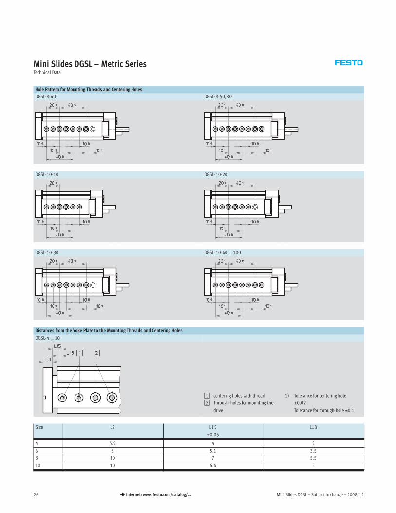
Hole Pattern for Mounting Threads and Centering Holes
DGSL-8-40 DGSL-8-50/80
DGSL-10-10 DGSL-10-20
DGSL-10-30 DGSL-10-40 … 100
Distances from the Yoke Plate to the Mounting Threads and Centering Holes
DGSL-4 … 10
1 centering holes with thread
2 Through-holes for mounting the
drive
1) Tolerance for centering hole
±0.02
Tolerance for through-hole ±0.1
Size L9 L15
±0.05
L18
4 5.5 4 3
6 8 5.1 3.5
8 10 7 5.5
10 10 6.4 5

2008/12 – Subject to change – Mini Slides DGSL 27� Internet: www.festo.com/catalog/...
Mini Slides DGSL – Metric SeriesTechnical Data
Dimensions – Size 12/16 Download CAD Data� www.festo.com/us/cad
1 Mounting thread (centering
sleeves included in scope of
delivery)
2 Through-holes for mounting the
drive
3 centering holes (centering
sleeves included in scope of
delivery)
4 Compressed air connection,
advancing
5 Compressed air connection,
retracting
6 Sensor slots for proximity sensor
SME/SMT-10
7 centering hole
General Dimensions
Size B1 B2 B3 B4 B5 B6 B7 B8 B9 B10 B11 B12 B13 B14 D1
12 60 59 47.6 24 10 9.2 14.7 24.3 59 6.4 35.35 35.2 50 36.7 M5
16 66 65 53.5 26.7 10 11.1 16.7 27.5 65 7.75 37.9 38 50.4 36.7 M5
Size D2
∅
D3
∅
D4
∅
D5
∅
D6 D7
∅
EE H1
±0.08
H2 H3 H4 H5 H6 H7 H8
12 8.8 7H7 5.5 8.8 M10x1 8H7 M5 36 34.8 34.7 8 15.1 20.35 28.2 19.3
16 8.8 7H7 5.5 9.2 M12x1 8H7 M5 40 38 39 8.5 16.7 20.6 31.7 20.8
Size H9 H10 H11 H12 H13 H14 H15 H16 H17 H18 H19 T3
+0.1
T4 T5 ß 2 ß 3
12 0.8 0.95 10 17.9 5.2 10.75 15.75 5.5 24.9 0.5 10 1.6 5.6 7.5 3 3
16 0.5 1.5 10 20 6.4 10.5 16.7 7 26.6 0.5 12.4 1.6 6.1 9 4 4

Mini Slides DGSL – Subject to change – 2008/1228 � Internet: www.festo.com/catalog/...
Mini Slides DGSL – Metric SeriesTechnical Data
Stroke-dependent Dimensions
Size Stroke L1 L2 L5 L6 L7 L8 L9 L10 L11 L15
±0.05
L16 L17 L18
±0.05
L21
12 10 106.2 68.6 42.4 – – 12 10 11.6 2.5 5.8 18.5 9 4.5 44
20 116.2 78.6 52.4
5 5 5 9 5
49
30 126.2 88.6 62.4 54
40 136.2 98.6 72.4 59
50 146.2 108.6 82.4 64
80 197.6 160 117 29 88
100 217.6 180 137
9
98
150 267.6 230 187 29 124
16 10 124.1 82.5 45 – – 14 12 13.6 2.5 6.8 21 10 5.5 54
20 134.6 93 54.6
3 5 5 5
59
30 144.6 103 64.6 64
40 154.6 113 74.6 69
50 164.6 123 84.6 74
80 194.6 153 114.6 35 89
100 243.6 202 134.6
35
113
150 293.6 252 184.6 138
Cushioning-dependent Dimensions
Size Cushioning L3 L4 ß 13
max. max. For adjusting the cushioning
stroke
For adjusting the end position
12 P 28.1 14.9 – 3
P1 26 12.8 3 6
Y3 36.9 23.7 – 3
16 P 42.3 26.1 – 4
P1 40 23.8 4 8
Y3 51.9 35.7 – 4

2008/12 – Subject to change – Mini Slides DGSL 29� Internet: www.festo.com/catalog/...
Mini Slides DGSL – Metric SeriesTechnical Data
Hole Pattern for Mounting Threads and Centering Holes
DGSL-12-10 DGSL-12-20
DGSL-12-30 DGSL-12-40
DGSL-12-50 … 100 DGSL-12-150
DGSL-16-10 DGSL-16-20

Mini Slides DGSL – Subject to change – 2008/1230 � Internet: www.festo.com/catalog/...
Mini Slides DGSL – Metric SeriesTechnical Data
Hole Pattern for Mounting Threads and Centering Holes
DGSL-16-30 DGSL-16-40 … 100
DGSL-16-150
Distances from the Yoke Plate to the Mounting Threads and Centering Holes
DGSL-12/16
1 centering holes with thread
2 Through-holes for mounting the
drive
1) Tolerance for centering hole
±0.02
Tolerance for through-hole ±0.1
Size L9 L15
±0.05
L18
12 10 5.8 4.5
16 12 6.8 5.5

2008/12 – Subject to change – Mini Slides DGSL 31� Internet: www.festo.com/catalog/...
Mini Slides DGSL – Metric SeriesTechnical Data
Dimensions – Size 20/25 Download CAD Data� www.festo.com/us/cad
DGSL-20
DGSL-25
1 Mounting thread (centering
sleeves included in scope of
delivery)
2 Through-holes for mounting the
drive
3 centering holes (centering
sleeves included in scope of
delivery)
4 Compressed air connection,
advancing
5 Compressed air connection,
retracting
6 Sensor slots for proximity sensor
SME/SMT-10
7 centering hole
General Dimensions
Size B1 B2 B3 B4 B5 B6 B7 B8 B9 B10 B11 B12 B13 B14 D1
20 85 84 68.85 34.5 20 14 21.4 36.35 83.4 10 48.9 49.2 64.1 48.6 M6
25 104 103 82.6 41.6 20 16.2 26.6 43.1 103 13.25 56.5 56.7 79.4 53.7 M6
Size D2
∅
D3
∅
D4
∅
D5
∅
D6 D7
∅
EE H1
±0.08
H2 H3 H4 H5 H6 H7 H8
20 11 9H7 6.6 11 M14x1 8H7 Gx 49 46.5 47.7 10.3 20.6 23.2 38.2 26.1
25 11 9H7 6.6 11 M16x1 8H7 Gx 60 57.5 58.5 10.5 23.4 31.2 48 34.5
Size H9 H10 H11 H12 H13 H14 H15 H16 H17 H18 H19 T3
+0.1
T4 T5 ß 2 ß 3
20 0.5 2 20 19.6 7.55 14.7 14.7 10 33.3 0.8 14.5 2.1 8.8 10 4 5
25 1 2 20 27.5 8.55 16.6 22.2 11 42.7 0.5 15.5 2.1 15.1 12 5 6

Mini Slides DGSL – Subject to change – 2008/1232 � Internet: www.festo.com/catalog/...
Mini Slides DGSL – Metric SeriesTechnical Data
Stroke-dependent Dimensions
Size Stroke L1 L2 L5 L6 L7 L8 L9 L10 L11 L15
±0.05
L16 L17 L18
±0.05
L21
20 10 141.2 84.6 59.1 – – 17 14 15.6 4.6 7.8 29.3 12 6.5 56
20 151.2 94.6 69.1
7 5 7 9 3 5
61
30 161.2 104.6 79.1 66
40 171.2 114.6 89.1 71
50 183.2 126.6 99.1 76
80 211.2 154.6 129.1 91
100 270.2 213.6 149.1 44 121
150 333.2 276.6 199.1 152
200 383.2 326.6 252.1 44 177
25 10 157.1 96 63.7 – – 22 15 16.6 4.6 8 30.9 14.5 6.5 645
20 167.1 106 72.2
5 3 9 5 5
69
30 177.1 116 82.2 74
40 187.1 126 92.2 79
50 197.1 136 102.2 84
80 253.1 192 132.2 55 112
100 286.1 225 152.2
55
129
150 338.1 277 202.2 154
200 388.1 327 254.2 179
Cushioning-dependent Dimensions
Size Cushioning L3 L4 ß 13
max. max. For adjusting the cushioning
stroke
For adjusting the end position
20 P 52.4 31.2 – 4
P1 50.1 28.9 4 8
Y3 55.5 34.3 – 4
25 P 51.9 30.5 – 55
P1 49.6 28.2 5 10
Y3 65.2 43.8 – 5

2008/12 – Subject to change – Mini Slides DGSL 33� Internet: www.festo.com/catalog/...
Mini Slides DGSL – Metric SeriesTechnical Data
Hole Pattern for Mounting Threads and Centering Holes
DGSL-20-10/20 DGSL-20-30/40
DGSL-20-50 DGSL-20-80
DGSL-20-100 … 200
DGSL-25-10 DGSL-25-20

Mini Slides DGSL – Subject to change – 2008/1234 � Internet: www.festo.com/catalog/...
Mini Slides DGSL – Metric SeriesTechnical Data
Hole Pattern for Mounting Threads and Centering Holes
DGSL-25-30/40 DGSL-25-50
DGSL-25-80 DGSL-25-100 … 200
Distances from the Yoke Plate to the Mounting Threads and Centering Holes
DGSL-20/25
1 centering holes with thread
2 Through-holes for mounting the
drive
1) Tolerance for centering hole
±0.02
Tolerance for through-hole ±0.1
Size L9 L15
±0.05
L18
20 14 7.8 6.5
25 15 8 6.5

2008/12 – Subject to change – Mini Slides DGSL 35� Internet: www.festo.com/catalog/...
Mini Slides DGSL-C/-E3 – Metric SeriesTechnical Data
Function
C – Clamping unit
E3 – End position locking
Size: 6 … 25
Wearing parts kits� 40
Note
Additional measures are required for
use in safety-related control systems;
in Europe, for example, the standards
listed under the EC Machinery Directive
must be observed. Without additional
measures in accordance with statutory
minimum requirements, the product is
not suitable for use in safety-related
sections of control systems.
General Technical Data – Clamping Unit
Size 6 8 10 12 16 20 25
Function – Mechanical clamping
– For fixing the slide in any position
– Frictional locking
Clamping type with effective direction of action From both sidesp g yp
Clamping via spring force, air pressure to release
Pneumatic connection M5
Mounting position Any
Static holding force [N] 80 80 180 180 350 350 600
Product weight [g] 10 10 15 15 50 50 50
Operating and Environmental Conditions – Clamping Unit
Operating medium Dried compressed air, lubricated or unlubricated
Min. release pressure [bar] 3
Max. operating pressure [bar] ≤ 10
General Technical Data – End-position Locking
Size 6 8 10 12 16 20 25
Function – Mechanical locking when the end position is reached
– For fixing the slide in the unpressurised, retracted state
– Positive locking
Clamping type with effective direction of action From both sidesp g yp
Clamping via spring force, air pressure to unlock
Pneumatic connection M5
Mounting position Any
Static holding force [N] 60 60 160 160 250 380 640
Product weight [g] 13 13 26 26 64 64 65
Operating and Environmental Conditions – End Position Locking
Operating medium Dried compressed air, lubricated or unlubricated
Operating pressure [bar] 3 … 8

Mini Slides DGSL – Subject to change – 2008/1236 � Internet: www.festo.com/catalog/...
Mini Slides DGSL-C/-E3 – Metric SeriesTechnical Data
Adjustable End Position Range
Size 1
6, 8 max. 1.5 mm
10, 12 max. 2.3 mm
16, 20, 25 max. 2.7 mm
Dimensions Download CAD Data� www.festo.com/us/cad
C – Clamping unit / E3 – End position locking
4 Compressed air connection
Size B15 D7 EE H20 L12
∅ C E3
6 7.2 12 10.7 21.2 7.3
8 9.9 12 10.5 21 7.3
10 11.2 16 11.8 21.2 10.5
12 14.8 16 M5 10.5 19.9 10.3
16 14 20
5
27.5 30.5 13
20 17 20 21.3 24.3 14
25 22.55 20 17.75 20.65 14
When using end position locking
(E3), the adjustable range of the rear
end position is reduced by the
following values.
1 Adjustable end position range

2008/12 – Subject to change – Mini Slides DGSL 37� Internet: www.festo.com/catalog/...
Mini Slides DGSL – Metric SeriesTechnical Data
Ordering Data
Size Stroke [mm] Part No. Type Size Stroke [mm] Part No. Type Size Stroke [mm] Part No. Type
With cushioning P With cushioning P1 With cushioning Y3
4 10 543910 DGSL-4-10-PA 4 10 543913 DGSL-4-10-P1A 4 10 –4
20 543911 DGSL-4-20-PA
4
20 543914 DGSL-4-20-P1A
4
20 –
30 543912 DGSL-4-30-PA 30 543915 DGSL-4-30-P1A 30 –
6 10 543916 DGSL-6-10-PA 6 10 543921 DGSL-6-10-P1A 6 10 –6
20 543917 DGSL-6-20-PA
6
20 543922 DGSL-6-20-P1A
6
20 –
30 543918 DGSL-6-30-PA 30 543923 DGSL-6-30-P1A 30 –
40 543919 DGSL-6-40-PA 40 543924 DGSL-6-40-P1A 40 –
50 543920 DGSL-6-50-PA 50 543925 DGSL-6-50-P1A 50 –
8 10 543926 DGSL-8-10-PA 8 10 543932 DGSL-8-10-P1A 8 10 –8
20 543927 DGSL-8-20-PA
8
20 543933 DGSL-8-20-P1A
8
20 –
30 543928 DGSL-8-30-PA 30 543934 DGSL-8-30-P1A 30 543938 DGSL-8-30-Y3A
40 543929 DGSL-8-40-PA 40 543935 DGSL-8-40-P1A 40 543939 DGSL-8-40-Y3A
50 543930 DGSL-8-50-PA 50 543936 DGSL-8-50-P1A 50 543940 DGSL-8-50-Y3A
80 543931 DGSL-8-80-PA 80 543937 DGSL-8-80-P1A 80 543941 DGSL-8-80-Y3A
10 10 543942 DGSL-10-10-PA 10 10 543949 DGSL-10-10-P1A 10 10 –10
20 543943 DGSL-10-20-PA
10
20 543950 DGSL-10-20-P1A
10
20 –
30 543944 DGSL-10-30-PA 30 543951 DGSL-10-30-P1A 30 543956 DGSL-10-30-Y3A
40 543945 DGSL-10-40-PA 40 543952 DGSL-10-40-P1A 40 543957 DGSL-10-40-Y3A
50 543946 DGSL-10-50-PA 50 543953 DGSL-10-50-P1A 50 543958 DGSL-10-50-Y3A
80 543947 DGSL-10-80-PA 80 543954 DGSL-10-80-P1A 80 543959 DGSL-10-80-Y3A
100 543948 DGSL-10-100-PA 100 543955 DGSL-10-100-P1A 100 543960 DGSL-10-100-Y3A
12 10 543961 DGSL-12-10-PA 12 10 543969 DGSL-12-10-P1A 12 10 –12
20 543962 DGSL-12-20-PA
12
20 543970 DGSL-12-20-P1A
12
20 –
30 543963 DGSL-12-30-PA 30 543971 DGSL-12-30-P1A 30 543977 DGSL-12-30-Y3A
40 543964 DGSL-12-40-PA 40 543972 DGSL-12-40-P1A 40 543978 DGSL-12-40-Y3A
50 543965 DGSL-12-50-PA 50 543973 DGSL-12-50-P1A 50 543979 DGSL-12-50-Y3A
80 543966 DGSL-12-80-PA 80 543974 DGSL-12-80-P1A 80 543980 DGSL-12-80-Y3A
100 543967 DGSL-12-100-PA 100 543975 DGSL-12-100-P1A 100 543981 DGSL-12-100-Y3A
150 543968 DGSL-12-150-PA 150 543976 DGSL-12-150-P1A 150 543982 DGSL-12-150-Y3A
16 10 543983 DGSL-16-10-PA 16 10 543991 DGSL-16-10-P1A 16 10 –16
20 543984 DGSL-16-20-PA
16
20 543992 DGSL-16-20-P1A
16
20 –
30 543985 DGSL-16-30-PA 30 543993 DGSL-16-30-P1A 30 543999 DGSL-16-30-Y3A
40 543986 DGSL-16-40-PA 40 543994 DGSL-16-40-P1A 40 544000 DGSL-16-40-Y3A
50 543987 DGSL-16-50-PA 50 543995 DGSL-16-50-P1A 50 544001 DGSL-16-50-Y3A
80 543988 DGSL-16-80-PA 80 543996 DGSL-16-80-P1A 80 544002 DGSL-16-80-Y3A
100 543989 DGSL-16-100-PA 100 543997 DGSL-16-100-P1A 100 544003 DGSL-16-100-Y3A
150 543990 DGSL-16-150-PA 150 543998 DGSL-16-150-P1A 150 544004 DGSL-16-150-Y3A
20 10 544005 DGSL-20-10-PA 20 10 544014 DGSL-20-10-P1A 20 10 –20
20 544006 DGSL-20-20-PA
20
20 544015 DGSL-20-20-P1A
20
20 –
30 544007 DGSL-20-30-PA 30 544016 DGSL-20-30-P1A 30 544023 DGSL-20-30-Y3A
40 544008 DGSL-20-40-PA 40 544017 DGSL-20-40-P1A 40 544024 DGSL-20-40-Y3A
50 544009 DGSL-20-50-PA 50 544018 DGSL-20-50-P1A 50 544025 DGSL-20-50-Y3A
80 544010 DGSL-20-80-PA 80 544019 DGSL-20-80-P1A 80 544026 DGSL-20-80-Y3A
100 544011 DGSL-20-100-PA 100 544020 DGSL-20-100-P1A 100 544027 DGSL-20-100-Y3A
150 544012 DGSL-20-150-PA 150 544021 DGSL-20-150-P1A 150 544028 DGSL-20-150-Y3A
200 544013 DGSL-20-200-PA 200 544022 DGSL-20-200-P1A 200 544029 DGSL-20-200-Y3A
25 10 544030 DGSL-25-10-PA 25 10 544039 DGSL-25-10-P1A 25 10 –25
20 544031 DGSL-25-20-PA
25
20 544040 DGSL-25-20-P1A
25
20 –
30 544032 DGSL-25-30-PA 30 544041 DGSL-25-30-P1A 30 544048 DGSL-25-30-Y3A
40 544033 DGSL-25-40-PA 40 544042 DGSL-25-40-P1A 40 544049 DGSL-25-40-Y3A
50 544034 DGSL-25-50-PA 50 544043 DGSL-25-50-P1A 50 544050 DGSL-25-50-Y3A
80 544035 DGSL-25-80-PA 80 544044 DGSL-25-80-P1A 80 544051 DGSL-25-80-Y3A
100 544036 DGSL-25-100-PA 100 544045 DGSL-25-100-P1A 100 544052 DGSL-25-100-Y3A
150 544037 DGSL-25-150-PA 150 544046 DGSL-25-150-P1A 150 544053 DGSL-25-150-Y3A
200 544038 DGSL-25-200-PA 200 544047 DGSL-25-200-P1A 200 544054 DGSL-25-200-Y3A

Mini Slides DGSL – Subject to change – 2008/1238 � Internet: www.festo.com/catalog/...
Mini Slides DGSL – Metric SeriesOrdering Data – Modular Products
Mandatory Data0M Options0O 0M
Module No. Function Size Stroke Clamping unit End position locking Cushioning Position sensing
543 902
543 903
543 904
543 905
543 906
543 907
543 908
543 909
DGSL 4
6
8
10
12
16
20
25
10 … 200 C E3 P
P1
Y3
A
Order
example
543 904 DGSL – 8 – 30 – E3 – Y3 A
Ordering Table
Size 4 6 8 10 12 16 20 25 Conditions Code Enter code
0M Module No. 543 902 543 903 543 904 543 905 543 906 543 907 543 908 543 909
Function Mini slide with recirculating ball bearing guide DGSL DGSL
– –
Size 4 6 8 10 12 16 20 25 …
– –
Stroke [mm] 10 10[ ]
20 20
30 30
– 40 40
– 50 50
– – 80 80
– – – 100 100
– – – – 150 150
– – – – – – 200 200
0O – –
Clamping unit – Built-on C
End position locking – With piston rod in retracted position 1 E3
0M – –
Cushioning Flexible cushioning rings/plates at both ends, end positions adjustable Pg
Flexible cushioning rings/plates at both ends, end positions adjustable, with fixed stop P1
– – Progressive shock absorber at both ends 2 Y3
Position sensing Via proximity sensor A A
1 E3 Not with clamping unit C 2 Y3 Minimum stroke 30 mm
Transfer order code
DGSL – – – – A

2008/12 – Subject to change – Mini Slides DGSL 39� Internet: www.festo.com/catalog/...
Mini Slides DGSL – Metric SeriesPeripherals Overview
Note
End stops must not be removed.
3 45
1 2 2
6 7
Accessories
Brief description � Page/Internet
1 Proximity sensor
SME/SMT-10
For position sensing. Can be integrated in sensor slot, thus no projecting parts 40
2 centering sleeve
ZBH
For centering loads and attachments
(the scope of delivery of the mini slide includes the centering sleeves)
40
3 One-way flow control valve
GRLA
For speed regulation 40
4 Push-in fitting
QSM
For connecting compressed air tubing with standard external diameters 40
5 Cushioning with shock absorber
Y3
For large loads and high speed. Ensures precise, metal-to-metal contact after the cushioning 40
6 Cushioning with stop
P1
Precision metal stop for small loads at low speed 40
7 Cushioning
P
Flexible stop for medium loads at medium speed
(standard version)
–

Mini Slides DGSL – Subject to change – 2008/1240 � Internet: www.festo.com/catalog/...
Mini Slides DGSL – Metric SeriesWearing Parts Kits and Accessories
Ordering Data – Wearing Parts Kits
Size Part No. Type
4 713743 DGSL-4-…
6 713744 DGSL-6-…
8 713745 DGSL-8-…
10 713746 DGSL-10-…
12 713747 DGSL-12-…
16 713748 DGSL-16-…
20 713749 DGSL-20-…
25 713750 DGSL-25-…
Ordering Data
For size Brief description Order code Part No. Type PU1)
centering sleeve ZBH Technical data� Internet: zbh
4, 6 For centering loads and attachments (the scope of – 189652 ZBH-5 10
8, 10, 12, 16
g ( p
delivery of the mini slide includes six centering sleeves) 186717 ZBH-7
20, 25
y g )
150927 ZBH-9
Connecting sleeve ZBV Technical data� Internet: zbv
8, 10 • For connecting mini slide DGSL with mini slide DGSL – 548802 ZBV-M4-7 3
12, 16
g
• Sizing information refers to the y axis 548803 ZBV-M5-7
3
20, 25
g y
548804 ZBV-M6-9
Shock absorber DYEF Technical data� Internet: dyef
4 Flexible cushioning, with metal stop P1 548370 DYEF-M4-Y1F 1
6
g, p
548371 DYEF-M5-Y1F
8 548372 DYEF-M6-Y1F
10 548373 DYEF-M8-Y1F
12 548374 DYEF-M10-Y1F
16 548375 DYEF-M12-Y1F
20 548376 DYEF-M14-Y1F
25 548377 DYEF-M16-Y1F
Shock absorber DYSW Technical data� Internet: dysw
8 Progressive shock absorbers, both ends Y3 548070 DYSW-4-6-Y1F 1
10
g , 3
548071 DYSW-5-8-Y1F
12 548072 DYSW-7-10-Y1F
16 548073 DYSW-8-14-Y1F
20 548074 DYSW-10-17-Y1F
25 548075 DYSW-12-20-Y1F
One-way flow control valve GRLA Technical data� Internet: grla
4, 6, 8 • For speed regulation – 175041 GRLA-M3-QS-3 1, , p g
• Only one GRLA-M3-QS-3 can be mounted onto the 175038 GRLA-M3
10, 12, 16
y Q
front of size 4 slides 193138 GRLA-M5-QS-4-D
20, 25 193144 GRLA-GÁ-QS-6-D
Push-in fitting QSM Technical data� Internet: qsm
4, 6, 8 For connecting compressed air tubing with standard – 153301 QSM-M3-3 10
10, 12, 16
g p g
external diameters 153304 QSM-M5-4
20, 25 153307 QSM-x-6
1) Packaging unit quantity

2008/12 – Subject to change – Mini Slides DGSL 41� Internet: www.festo.com/catalog/...
Mini Slides DGSL – Metric SeriesAccessories
Ordering Data – Proximity Sensors for C-slot, Magneto-resistive Technical data� Internet: smt
Type of mounting Switch Electrical connection, Cable length Part No. Typeyp g
output
,
connection direction [m]
yp
N/O contact
Insertable in the slot from PNP Cable, 3-wire, in-line 2.5 525915 SMT-10F-PS-24V-K2,5L-OE
above, flush with cylinder Plug M8x1, 3-pin, in-line 0.3 525916 SMT-10F-PS-24V-K0,3L-M8D, y
profile Plug M8x1, 3-pin, lateral 0.3 526675 SMT-10F-PS-24V-K0,3Q-M8D
Insertable in the slot PNP Plug M8x1, 3-pin, in-line 0.3 173220 SMT-10-PS-SL-LED-24
lengthwise Cable, 3-wire, in-line 2.5 173218 SMT-10-PS-KL-LED-24
Ordering Data – Proximity Sensors for C-slot, Magnetic Reed Technical data� Internet: sme
Type of mounting Switch Electrical connection, Cable length Part No. Typeyp g
output
,
connection direction [m]
yp
N/O contact
Insertable in the slot from Contacting Plug M8x1, 3-pin, in-line 0.3 525914 SME-10F-DS-24V-K0,3L-M8D
above, flush with cylinder
g
Cable, 3-wire, in-line 2.5 525913 SME-10F-DS-24V-K2,5L-OE, y
profile Cable, 2-wire, in-line 2.5 526672 SME-10F-ZS-24V-K2,5L-OE
Insertable in the slot Contacting Plug M8x1, 3-pin, in-line 0.3 173212 SME-10-SL-LED-24
lengthwise
g
Cable, 3-wire, in-line 2.5 173210 SME-10-KL-LED-24
Note
Proximity sensors SME are not
permitted for size 4.
Ordering Data – Connecting Cables Technical data� Internet: nebu
Electrical connection, left Electrical connection, right Cable length Part No. Type, , g
[m]
yp
Straight socket, M8x1, 3-pin Cable, open end, 3-wire 2.5 541333 NEBU-M8G3-K-2.5-LE3g , , 3 p , p , 3
5 541334 NEBU-M8G3-K-5-LE3
Angled socket, M8x1, 3-pin Cable, open end, 3-wire 2.5 541338 NEBU-M8W3-K-2.5-LE3g , , 3 p , p , 3
5 541341 NEBU-M8W3-K-5-LE3


Product Range and Company Overview
The Broadest Range of Automation Components
With a comprehensive line of more than 30,000 automation components, Festo is capable of solving the most complex
automation requirements.
Supporting Advanced Automation… As No One Else Can!
Festo is a leading global manufacturer of pneumatic and electromechanical systems, components and controls for industrial automation,
with more than 12,000 employees in 56 national headquarters serving more than 180 countries. For more than 80 years, Festo has
continuously elevated the state of manufacturing with innovations and optimized motion control solutions that deliver higher performing,
more profitable automated manufacturing and processing equipment. Our dedication to the advancement of automation extends beyond
technology to the education and development of current and future automation and robotics designers with simulation tools, teaching
programs, and on-site services.
Quality Assurance, ISO 9001 and ISO 14001 Certifications
Festo Corporation is committed to supply all Festo products and services that will meet or exceed
our customers’ requirements in product quality, delivery, customer service and satisfaction.
To meet this commitment, we strive to ensure a consistent, integrated, and systematic approach
to management that will meet or exceed the requirements of the ISO 9001 standard for Quality
Management and the ISO 14001 standard for Environmental Management.
PLCs and I/O Devices
PLC's, operator interfaces, sensors
and I/O devices
Pneumatics
Pneumatic linear and rotary actuators,
valves, and air supply
Electromechanical
Electromechanical actuators, motors,
controllers & drives
A Complete Suite of Automation Services
Our experienced engineers provide complete support at every stage of your development process, including: conceptualization,
analysis, engineering, design, assembly, documentation, validation, and production.
Complete Systems
Shipment, stocking and storage services
Custom Control Cabinets
Comprehensive engineering support
and on-site services
Custom Automation Components
Complete custom engineered solutions
© Copyright 2008, Festo Corporation. While every effort is made to ensure that all dimensions and specifications are correct, Festo cannot guarantee that
publications are completely free of any error, in particular typing or printing errors. Accordingly, Festo cannot be held responsible for the same. For Liability and
Warranty conditions, refer to our “Terms and Conditions of Sale”, available from your local Festo office. All rights reserved. No part of this publication may be
reproduced, distributed, or transmitted in any form or by any means, electronic, mechanical, photocopying or otherwise, without the prior written permission of
Festo. All technical data subject to change according to technical update.
Printed on recycled paper at New Horizon Graphic, Inc., FSC certified as an environmentally friendly printing plant.

Festo North America
United States
Customer Resource Center502 Earth City Expy., Suite 125Earth City, MO 63045
For ordering assistance, or to find your nearest Festo Distributor,Call: 1.800.99.FESTOFax: 1.800.96.FESTOEmail: [email protected]
For technical support,Call: 1.866.GO.FESTOFax: 1.800.96.FESTOEmail: [email protected]
HeadquartersFesto Corporation395 Moreland RoadP.O. Box 18023Hauppauge, NY 11788www.festo.com/us
Sales Offices
AppletonN. 922 Tower View Drive, Suite NGreenville, WI 54942
Boston120 Presidential Way, Suite 330Woburn, MA 01801
Chicago1441 East Business Center DriveMt. Prospect, IL 60056
Dallas1825 Lakeway Drive, Suite 600Lewisville, TX 75057
Detroit - Automotive Engineering Center2601 Cambridge Court, Suite 320Auburn Hills, MI 48326
New York395 Moreland RoadHauppauge, NY 11788
Silicon Valley4935 Southfront Road, Suite FLivermore, CA 94550
Design and Manufacturing Operations
Canada
Headquarters
Festo Inc.
5300 Explorer Drive
Mississauga, Ontario L4W 5G4
Call: 1.905.624.9000
Fax: 1.905.624.9001
Email: [email protected]
www.festo.com/ca
Mexico
Headquarters
Festo Pneumatic, S.A.
Av. Ceylán 3, Col. Tequesquinahuac
54020 Tlalnepantla, Edo. de México
Call: 011 52 [55] 53 21 66 00
Fax: 011 52 [55] 53 21 66 65
Email: [email protected]
www.festo.com/mx
Festo Worldwide
Argentina Australia Austria Belarus Belgium Brazil Bulgaria Canada Chile China Colombia Croatia Czech Republic Denmark
Estonia Finland France Germany Great Britain Greece Hong Kong Hungary India Indonesia Iran Ireland Israel Italy Japan
Latvia Lithuania Malaysia Mexico Netherlands New Zealand Norway Peru Philippines Poland Romania Russia Serbia Singapore Slo-
vakia Slovenia South Africa South Korea Spain Sweden Switzerland Taiwan Thailand Turkey Ukraine United States Venezuela
www.festo.com
East: 395 Moreland Road, Hauppauge, NY 11788
Central: 1441 East Business Center Drive, Mt. Prospect, IL 60056
West: 4935 Southfront Road, Suite F, Livermore, CA 94550


