C.P. No. 133 (14,648) A.R.C. Techntcal Report MINISTRY OF SUPPLY AERONAUTICAL RESEARCH COUNCIL CURRENT PAPERS Air Cooling Methods for Gas Turbine Combustion Systems BY F. J Bayley, M.Sc. LONDON : HER MAJESTY’S STATIONERY OFFICE 1953 TEN’ SHILLINGS NET
Transcript
C.P. No. 133 (14,648)
A.R.C. Techntcal Report
MINISTRY OF SUPPLY
AERONAUTICAL RESEARCH COUNCIL
CURRENT PAPERS
Air Cooling Methods for Gas Turbine Combustion Systems
BY
F. J Bayley, M.Sc.
LONDON : HER MAJESTY’S STATIONERY OFFICE
1953
TEN’ SHILLINGS NET
C.P. No. 133
NAlTONAL GAS 7KQBm ESTABLISHMEXT
Report No. R.lO1
hwt, 1951.
Air Cooling Uethods for Gas Turbine Combustion Systems
-by-
F. J. Bayley, M.Sc.
This paper prcssnts an account of the whole of the work which
has been done at the National. Gas Turbmc Establishment on the problem
of air-oooling gas turbzno conbustxon systems. Each of the different
methods of wall oooling is dxcussed separately and the theory and
nlC0han.i~~ of the cooling process is developed from first principles.
Certazn of the methods have beon the subjects of experimental
investigations and in such cases a brief description of the test
arrsngements is given and the results are analysed and discussed.
Sufficient information is gxven to enable ‘aqy of the various methods to
be applied to practxdl wal.l cooling problems and, in a conclusion to
the report, their relative advantages and disadvantages for difYerent
gas turblnc applications are considered. It is shown that "sweat",
or offusion-cooling, IS by far the most effective and efficient method,
v&de tho use of "louvred" surfaces represent? the nearest practical.
approach to this ideal whoh is possible while suitable porous materials
remain unavailable. !Cho remaining methods - convective cooling by
externsl sir flow, looslised air injection to form a protective blanket
of coolant, and a combination of these two - are al.1 less effective,
but provide means whereby conventIonal ocmbustion systems may be
conveniently cooled without the need far porous materials or the weight
increases associated with louvred wslls.
-2-
Report No. R.101
COPTENTS
1.0 Introduction
2.0 Convective Cooling by External Air Flow
2.1 Theory of Operation 2.2 Estimation of the Heat Transfer Coefficients in the System
2; The use of Fins or Secondary Surfaces The Pressure Drop through the System and its Effects
3.0 The Use of "Louvred" Surfaces for Cooling
3.1 Theory of Operation
::: Estirmtion of Heat Transfer Coefficients m the System Some Calculnted Results
3.4 The Pressure Drop throy?h the System \
4.0 The Use of Porous Yklls - "Sweat Cooling"
4.1 Test Arrangements and Results 4.2 Analysis and Discussion of Test Results 4.3 Sweat Cooling in Practice 4,& The Presswc Drop in Porous Walls
5.0 Cooling by Localised Air Injection
5.1 Theory of Operation 5.2 An Experimsntal Investigation 5.3 Analysis of Test Results 5.4 The Practical Application of the Method of Cooling
6.0 The Effect of Combined Convective Cooling by External Air Flow and Localised Air Injection
6 . 7 Theory of Operation
7.0 Conclusion - A Comparison between the Different Methods of Wall Cooling.
:, ck~o~,rl cdgmento
Refcrunies
s
4
4
4
2 7
a a
10
::
II
::
::
17
18 19 20 22
22
23
UC
26
27
-3-
Report No. R.101
APPENDICES
Appendix I Nomenclature Used in the Text 28
Appendix II A Note upon Heat Transfer in Combustion Ctmmber 30 Flame Tubes
Appendix III A relation between the Overall Heat Transfer 32 Coeffd.ent belmeen a Gas Stream and a Y'all and the Reynolds Analogy Convection Coefficient
Appendix IV A General Solution for the Temperature Distribution 33 in the Ideal Boundmy Layer formed by LCoalised Air InJoction.
ILLUSTRATIONS
Fig. No. Title
1 Effioiency-of Secondmy Surfaces
2 The Cooling Effect in a Louvred Wall
3 Test Rig for Porous Walled Ihmt
4 Observed Cooling Effect in a Porous Wall
5 Effeot of Air Flow on Rate of Heat Transfer to a Porous Wall
6 An Improved Correlation of the Cooling Effects
7 Calculated Wall Temperature Curves
8 The Effect of Injection Velocity on the Degree of X5xiw in the Boundary Layer
9 8.6 IO The Effect of Reynolds Number upon the Rota of Decay of a Boundary Layer
11 A Comparison between the Different &&hods of !liall Cooling
-4-
Report No. R.lO1
1.0 Introduction
The advantages to be gained by the use of higher gas temperatures in internal combustion turbines are no well establlsheed and hsve been cmprehensivcly dealt with in the literature. Equally well established, however, are the dd'ficulties associated with the use of these higher temperatures, and considerable research effort is going into attempts to solve them. The turbine especially the highly stressed rotor blades has naturally been the obJect of most of this effort, but s comp!xent vrhlch has hitherto recclved much less attention has been shown by recent experience to present difficulties almost as critical as those of the turbine. This component is the combustion system.
It follows from the arrangement of a typical gas turbine combustion system that the flame tube ~111 be subJected to tenperntures considerably higher than prevail at the turbine inlet , and nlthough not highly stressed, experience has shown that severe distortion and even complete failure of flame tubes can be expected in perlods of less than 1000 hours. ~Mle this is of less importance in aircraft cnglne practice where frequent complete overhauls and renewal Of mJor components are usual, it makes some form of cooling essential for the combustion systems of industrial gas turbine plant required to operate contlnu- ously rind reliably for long periods.
Air appears as the logical coolant for gns turbine combustion systems, and its use is assumed in each of the wall cooliw methods which are discussed in this paper. There is always an excess avallable over the amount of air required to efflclently burn the fuel in the prlmnry zonc of n combustion chamber, anil a proportion of this rray be used most conveniently for cooling purposes. The nnin advantage to be gained by so doing 1s that no bent is lost from the min working cycle of the engine , as is necessarily the case with, for instance, water cooling. The gas temperatures associated with the air cooling system allay be so arranged that after the last of the coolant has mixed with the main stream, the resultant temperature corresponds wzth the maximum acceptable to the turbine.
The several alternative methods of achieving wall cooling are considered separately in the text which follows. It is assumed in all cases that the necossnry air flow x3 independently metered , and this will hsve to be arranged by the designer of a particular system, who must ensure that the fluid static pressure drops in the coolant and the rrain stream, from the initial point of separation to where they finally merge again, are equal.
2.0 Convective Cooling by Externsl Air Flopr
This method of cooling is the most sxnple and convenient to arrange and 1s commonly used. It 1s especially suitable for "straight-through" combustion cbambcr flame tubes, m whxh the dilution air is n&e to flow in an nnnulor passage, one bounding wall of which is the surface to be cooled. There is a convective heat transfer process between the air and the hot wsll and the latter nttalns an equlllbriux temperature which is dependent upon the ratio of the heat transfer rntes upon its two sides. The cooling air passage need not necessarily be annular and in fact is only so In the case of the cylindrical combustion chnmbcr, but it is very conveniently formed between the flame tube or a similar liner ad on outer pressure casing, the grip being dlmensloned by pressure drop considerations as shown later.
2.1 Theory of Operation
The temperature of the wall at any point in the cooling system, nssuming lnfinlte radio1 conduction and none in a J.ongit&nal direction, is given by t'nc equation:-
The temperature of the cooliw air, On, is o variable which &pen& upon the thermd capacity of the air flew and the hcct transfer mix. Consider n short length of the system, 8x, distant x from the origin where 0, The heat balance may be written down as
In most cases F is a linenr function of x , the constant being the perimeter, which for the cylindrical surface is 7~13.. Thus in the limit, for the cylindrlcel surface, equation (2) becomes:-
where Kl E b . na cp . Tia
Substituting for h from equation (lo) gives
dB, K1 . @a =-
Kl l TG
ax K2 *-
K2
. . . . . . . . . . (2n)
. . . . . . . . . . (2b)
h, where K2 = 1 + - hs
h' xc3 =- cp l":a
where h' is the overall heat transfer coefficient between the hot gas 3rd the cooliw air and 1s given by:-
-?_ -1-+L h' = ha h&T
Integrating equation (2b) with the aid of the factor exp. XKI Yqj' and applying
the end condition that Ba = Ta when x = 0, gives the solution:-
Tg-0, = T&z . . . . . . . . . . (3)
Thus, the wall temperature at any point in a system rmy be evaluated by first calculating the air temperature nocording to equation (3) and then substituting the result into equation (lo),
A list of symbols and their meanings is given in Appendix 1.
-6-
Report No. R.101
2.2 Rstimstion of the Heat Transfer Codflcients in the System
If n calculation is to be mode according to the theory set out above, then n knowledge is required of the heat transfer coeffiolents on the two sides of the wall to be cooled.
Unless experimental results are avniloble from tests made with exactly similar conditions of flow, it is impossible to lrake &her than an approxinmte estinnte of the heat transfer coeffiuient between the hot gas and the wnll. This is especially the case with combustion chamber flame tubes in which there arc the oomplicoting effects of flame rndiation and often violent swirl, and n note about heat transfer conditions in these is given in Appendix 2. However, where developed turbulent flow may be expected as in long uninterrupted lengths of duoting, the well-kncmn standard formula, which is reproduced here wy be used to predict the heat transfer coefficient:
h.a, G 0.8
-= A 0.02 p.-; . . . . . * . . . . (4)
This equation assumes that the Prandtl number, g$&, is constant at 0.71, the value for air.
The problem of estimating the heat transfer coefficient on the air side is usually less severe. If the equivalent diameter, &, defined as
ae = 4 x Area avaIlable for flow Wetted Perimeter '
is used, and the passage length is large compared with the value of this prameter, then equation (4) may be applied to conditions of turbulent flow. There is some difference of opinion as t? whether the total wetted perimeter or the heated perimeter alone should be used to define the equivalent diameter in the case of the annulus having one wall only heated, but the little experimental evdence that is available indicates that the former procedure is correct. In nny event, the form of equation (4) is such tkst the difference between the heat transfer coefficients predioted by the two definitions of the equivalent diameter is only about 15$.
Equation (4) IID. be used with reasonable accuracy down to values of the Reynolds number, deG pg, of about 2,000, but as this lower limit is approached 7 the estimated values of the heat transfer ooefflcient become increasingly liable to error. Under such conditions the Nusselt number hde/h becomes n function of the length/diameter ratio and other variables, but if the theoretically calculated values of this for truly laminnr flmf, as given in reference (3), are used when the Reynolds number is less than 2,000, and equation (4) used abwe this voluo, then the estimated hent trnnsfer rote will be on the conservntive side, since it is likely to be increased unpredictably by natural convection nnfi entry length effects.
2.3 The use of Fins or Secondary Surfaces.
To increase the rate of heat transfer on the cooling air side of the system, use my be wde of fins, or secondary surfaces, which increase the effective nren for heat exchange. Secondary surfaces are not one hundred per cent effioient, that, is to say, the addition of a fin area equd to the base nrea does not double the rote of heat transfer, because the temperature drop that must occur along the fin if heat is to be conducted away from its base, reduces the potentinl
-7-
Report No. R.101
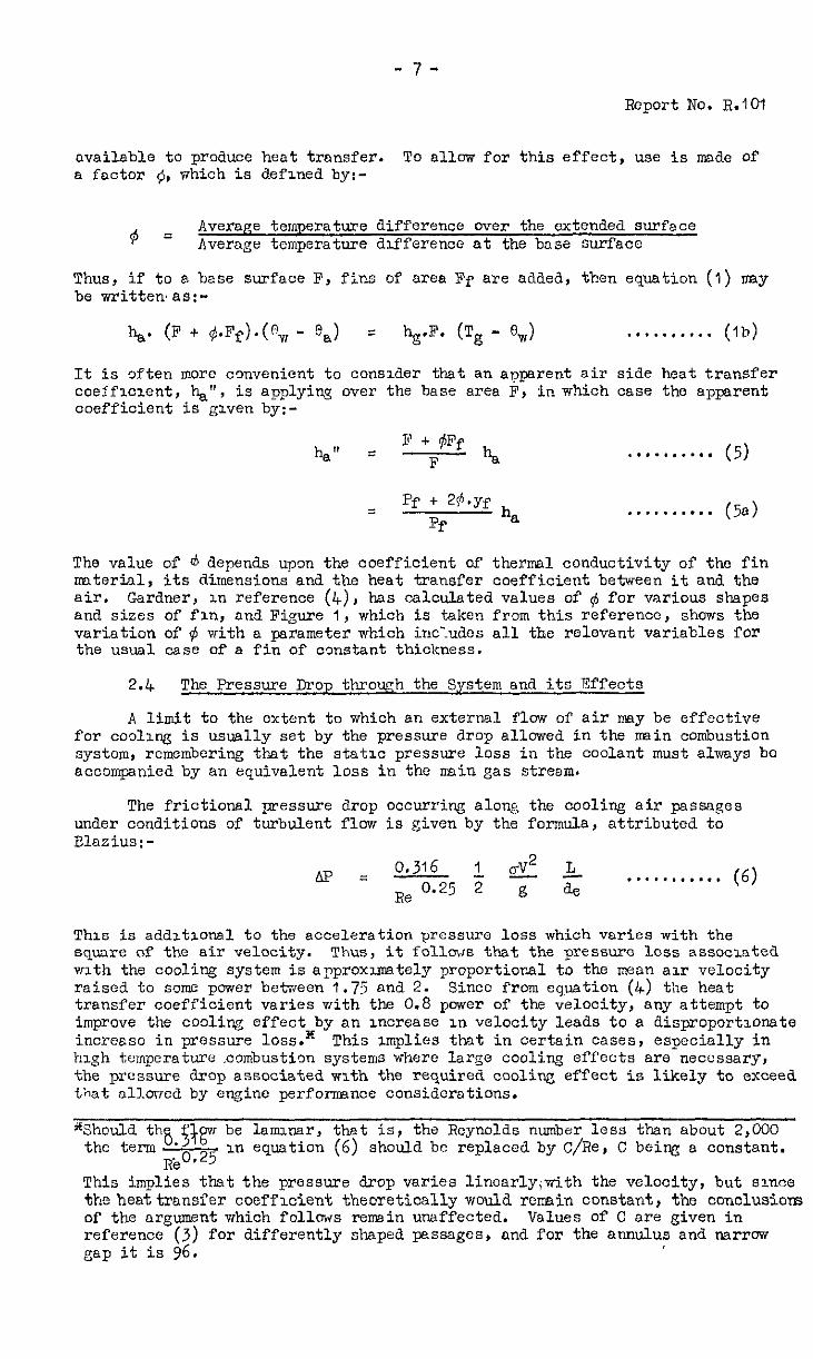
available to produce heat transfer. To allow for this effect, use is made of a factor 0, which is defined by:-
Q = Average temperature difference over the extended surface Average temperature difference at the base surface
Thus, if to a base surface F, fins of area Pf are aMed, then equation (1) may be written,as:-
It is often more convenient to consider that an apparent air side heat transfer coefficient, hag", is applying over the base area F, in which case the apparent coefficient is given by:-
ha" = B t #Ff
F k
= Pf + 24.Yf Pf
h *
.*........ (5)
. . . . . . . . . . (5e)
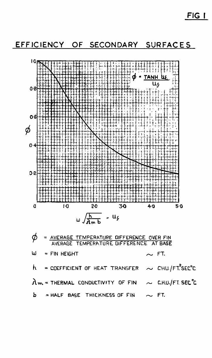
The value of o depends upon the coefficient of thermal conductivity of the fin material, its dimensions and the heat transfer coefficient between it and the air. Gardner, in reference (4), has calculated values of $ for various shapes and sizes of fin, and Figure I, which is taken from this reference, shows the variation of Q with a parameter which inc?udos all the relevant variables for the usual case of a fin of constant thickness.
2.4 The Pressure Drop throwh the System and its Effects
A limit to the extent to which an external flow of air may be effective for cooling is usually set by the pressure drop allowed in the main combustion system, rcmemboring that the static pressure loss in the coolant must always bo accompanied by an equivalent loss in the main gas stream.
The frictional pressure Zrop occurring along the cooling air passages under conditions of turbulent flow is given by the formula, attributed to Blosius:-
Lx? = 0,316 1 CT2 4. Re 0.25 2 -ii- a,
. . . . . . . . . . . (6)
This is additaonal to the acceleration pressure loss which varies with the square of the air velocity. Thus, it follows that the pressure loss associated with the cooling system is aPproximately proportional to the mean air velocity raised to some power between 1.75 and 2. Since from equation (4) the heat transfer coefficient varies with the 0.8 power of the velocity, any attempt to improve the cooling effect by an increase in velocity leads to a disproportionate increase in pressure loss.* This implies that in oertain cases, especially in high temperature combustion systems where large cooling effects are necessary, the pressure drop associated with the require& cooling effect is likely to exceed that allorrod by engine perforeence considerations.
"",3~~Zl~~@w be laminar, that is, the Reynolds number less than about 2,000
RbO.25 In equation (6) should be replaced by C/Re, C being a constant.
This implies that the pressure drop varies 1inearly;with the velocity, but since the heattransfer coefficient theoretically would rennin constant, the conclusions of the argument which follows rewin unaffected. reference (3) for differently shaped passages
Values of C are given in , and for the annulus and narrow
gap it is 96,
-8-
Rcoort No. R.lO1
3.0 The Use of "Louvred" Surface for Cooling*
In the previous section it was shown how, by the use of secondary surfaces to obtain er #enter effective wea for heat transfer on the air side of a cooled wall, the cooling effect could be increased. The "louvred" wall works on an extension of this principle, since the method of construction is such that the area for heat extraction is much larger than thqt available for heat input from the hot gases. The surface to be cooled is so made that there are nmny 811~11 independent passages along which the cooling air may flow radially, finally emerging to mix with the nsin gas stream. This nay be achieved by constructing a circular flame tube, for instance, from a series of annular discs, clamped 80 that there is a gap between each pair to form the air passages. The inner circumferences form the bounding wall of the main gas stream. A detailed description of a combustion chamber with the flame tube so constructed is given in reference (5), although in this case, to reduce the number of ring8 required to nuke up the flame tube length, they are stamped to form conical frustra, and. hence the passages are inclined to the true radial direction.
3.1 Theory of Operation
To determine the temperatures in such a system, in which temperature variations through the fin thickness are neglected, consider an elementary length of fin which is distant x from the point of entry of the oooling air to the pssages. There is a balance between the heat convected to the air over the ler@h being considered and that conducted into and out of it, which may be written as:-
ha. 6Fa (0, - @a) = X,,Cm + 2 . 6-z) - 2
I = . . . . . . . . . . (7)
If f is the heat transfer area per unit length of fin, it my be regarded in most cases as independent of x without serious error.
Thus rewriting equation (7) we get:-
NW consider the heat balance of the air in pessing the length 6x
Wa is, in this case, the flav of air per passage. In the limit, equation (8) beoomes:-
..a....... (Ee)
"Phis method of construction for oooled flame tube walls is the subject of British Fatent No. 642,257, held by the "Shell" Refining and Marketing Co. Ltd.
-9-
Rowrt I'J3. R.lO1
from equation (8a) and writing
we get &7 &k* 9 z3- + - - ax*
K 4 G&L = 0 ax
. . . . . . . . . . (9)
The solution of this differentiol equation has the form
ea = A t Ale 01x t A2e 82X . . . . . . . . . . (10)
where a = a,, a2 are the roots of the auxdiary equation
K3 a* + a - I$+ = 0 . . . . . . . . . . (11)
and A, A,, A , are constants of integration. Substituting in eqmtion (8a) for 0, from equagion (10) gives the complete solution for t'ne wall temperature at any pomt, x, ns:-
% =# A + Al (1 t al IC3)e OIX t A*(1 t a2 K3)oap . . . . . . (12)
To cpply this eqwtion to a given design we need three sepnrntc end conditions with nhioh to evaluate the constants 0:' integration, A, A,, AZ. The three most convenient conditions are:-
(a) At the hot end of the fin, at x = L, all the heat passes by conduction through the surface, i.e.,
(dew) Hi (ax)x=L = x,.
., . * *.. . . . (a)
Hi is the hcnt input to the inner surface of each fin from the hot gases.
(b) At entry to the passages, x = 0, the cooling air temperature is known, i.e.
T, = A t A, + A2 . . . . . . . . . . (b)
(c) If heat 'losses from the c,old side of the system arc neglected, then the air receives ~i.?ent,unLts,pcr,.seooSd~i~~.its -gaPssage through the wall, and kncdrv,i$s ~s.s,f.low rate at@ spe_clf'$.c pent, the exit temperature is known, i.e.,
T Hi ma + -‘ =
ya.Cp ,A + J+?'~ '+ A2ea2L .a,... (o)
I
In using th& m+hod of cilloulntion 3t will be found, rmst convenient to obtain the values of A, A,! A*, ln terms of the unkuuwn Hi. Then suvze it is
- 10 -
Report No. R.lO1
the value of @v,. et the hot end of the fin, at x = L, say, T,, which is usually require6 e. final equation can be obtaineawhich has only TV as an unknown since we have:-
Hi = bg . Fg . (Tg - Tw) .**....... (13)
Fg in this equation is, of oourse, the effective area available for heat transfer from the hot gases to each fin.
3.2 Estirration of the Heat Transfer Coefficients in the System
The evaluation of the heat transfer coef'flcient on the gas side presents difficulties similar to those d.escr$.bed in the previous section, with the additions1 covlication of the unknown effect upon the convective heat transfer process of the d&continuous nature of the wall ana of the injection of the cooling air. With the lack of more precise experimntal evidence, all that oan be aone to allow for the effects of these factors, is to assume that they cancel each other out.
In the &ir pssages, with the necessarily sndl gaps, the air flow is likely to be laminar in which case the Nusselt number should be taken ns 8.2, which is the theoretical value given by Smith in reference (3). Should the Reynolds number exceed 2,000, as previously described, equation (4) lrply be used., with the equivalent diameter de, taken as twioe the passage height.
3.3 Some Calculated Results
Fqure 2 shuws the results of some oaloulnticns ride according to the theory described in this section, for a typical hot gas duct similar in construction to ttit described in reference (5). The effect of a varying air flow upon the maximum temperatures reached by the wall when constructed from either stainless steel or copper is shown by Figure 2a, while the effect of the different thermal conauotivities of these two metals upon the temperature distribution in the system is shopm by Figure 2b. Although the maximum tenrpera- ture reached by the copper wall, (ocefficient of conductivity = 216. C.H.U./ hr.ft.'C.), is less that thd obtained with stainless steel fins, (coefficient of conductivity = 11 . C.H.U./hr.ft.%.), the meld temperature for 8% of the fin length is actually higher.
3.4 The Pressure Drop through the System
To estimate the pressure drop associatea with the flaw of air through the passages in a louvred wall, equation (6) may be usea with the factor C/Re replacing 0.316/~~0.25 if the Reynolds number is less than 2,000, as explained in the footnote of page 7. Unlike the difficulty met with in the method of cooling discussed in the previous section with regard to pressure drop, the problem with the louvred wall is dually to make the pressure drop sufficiently large for there to be any control of the distribution of the air over the surface to be cooled. If the gaps between each element of the wall are too big, and the throughway ratio excessive , the pressure drop across the wall is so low as to be of the order of thst in the nnin gas stream resulting from its viscid flow down the duct. In such D ease, most of the air will flow through the wall ot the downstream end of the duct, while the upstream surface till receive an imaepte supply of coolant. It is usually necessary with practical louvred walls to use far more air than would really be necessary for cooling were it possible to distribute a lesser amount uniformly over the surface.
- 11 "
Report No. R.lO1
4.0 The Use of Porous "Jells - "Swent" cooli%
7ith the louvre method of construction for n cooled ~311, cs discussed in the last section, a surface was cbtoined whioh contnined n number of passages for cooling air flov, in which o convective hent transfer process removed the hent that wils conducted bock through the metal of the wall from its hot inner SLdr.W. The porous wall any bc considered as workiw on the some principle oarried to its ultimate extreme, i.e. the pores in the vnll provide tho many sllnll passages, and hence n very large area over which heat transfer between the wall and the cooling air may trike place. In addition, since there arc so mny ssnll passages scattered unif'ornily over the surface of the wall, the air Jets emerging from each innnediatoly ooalesoc to form o continuous cool boundary layer which, under certain conditions, drnstionlly reduces the rate of heat transfer from the hot gas, and so adds to the cooling effect.
The earliest experimental evidence of the effectiveness of "sweat" cooling, as cooline by means of porous ~11s is commonly called, was published by Duwes and Wheeler in reference (6). Their porous test section was, however, only 1.5 inches long by 1 inch diameter and the need was therefore felt for some odditionol experimental data obtained from tests on a porous walled duct com- plrable in size to the gas turbine components to which it was hoped eventually to apply the technique of sweat coolin?. A brief description of these tests and the npporatus used for them is given belcw.
4.1 Test Arrangements and Results
The arrangement of the porous vralled test section is shown by Figure 3. It vos supplied with hot gas ot varying temperatures from a combustion chamber some 8 fzet upstream, while the cooling air supply was led to the airtight box which surrounded it, and which served to damp cut pressure fluctuations trans+ mitted irom the blcwer. The air flow rate vms measured by an independent standard orifice plate, and the gas mass flow was obtained by differenoc between the air mass flow and the total value os given by a measuring section in the snin supply line from the blower. The gas temperature was measured by moans of a single shielded chromel-nlumol thermocouple just upstream of the test section, while the two used for measuring the air temperatures are shcvn in the sketch.
The porous duct itself, which rms 6.4 inches in diameter rind 21 inches lorg, was rolled from two sheets of a porous bronze, which was ori&mlly developed as n filtering medium , and which therefore left much to be desired in the way of strength and resistance to high temperature. The necessary Joints in the duct were made by brazing , a method which was not very satisfactory in that it led to appreciable nrens of the surface becomiw blocked near the Joints, and the inevitable overheating caused embrittlement of the metal. The line of eleven thermocouples used to measure walltompcratures, and which were plug@l into the ~mll in the mcnncr shown in the saoll sketch in Pigure 3, VAS placed diagonally opposite the lot-gitudioal brazed Joint, so that the non- porous and hence uncooled, orcns should have ss little affect as possible upon the observations of wall temperature.
In the ccurso of the experiments , readiws of wall temperature were token for various zas streamtemperatures and gas and air mnss flcws. The results are shown plotted in Figure 4 os cooli% efficiency versus the ratio, cooling air IMSS flow per unit surface area/gas flow per unit duct cross-sectional arca, a correlation suggested by Duwes and V!heeler in reference (6). The cooling efficiency, ~1, is defined by
Tg - 0,' n = T ST'
6 n
- 12 -
Feport No. R.lO1
%' being the meen of the observed wall temperature readings, those ct each end of the duct being neglected, however, because of the large effect upon them of the uncooled areas under the flanges.
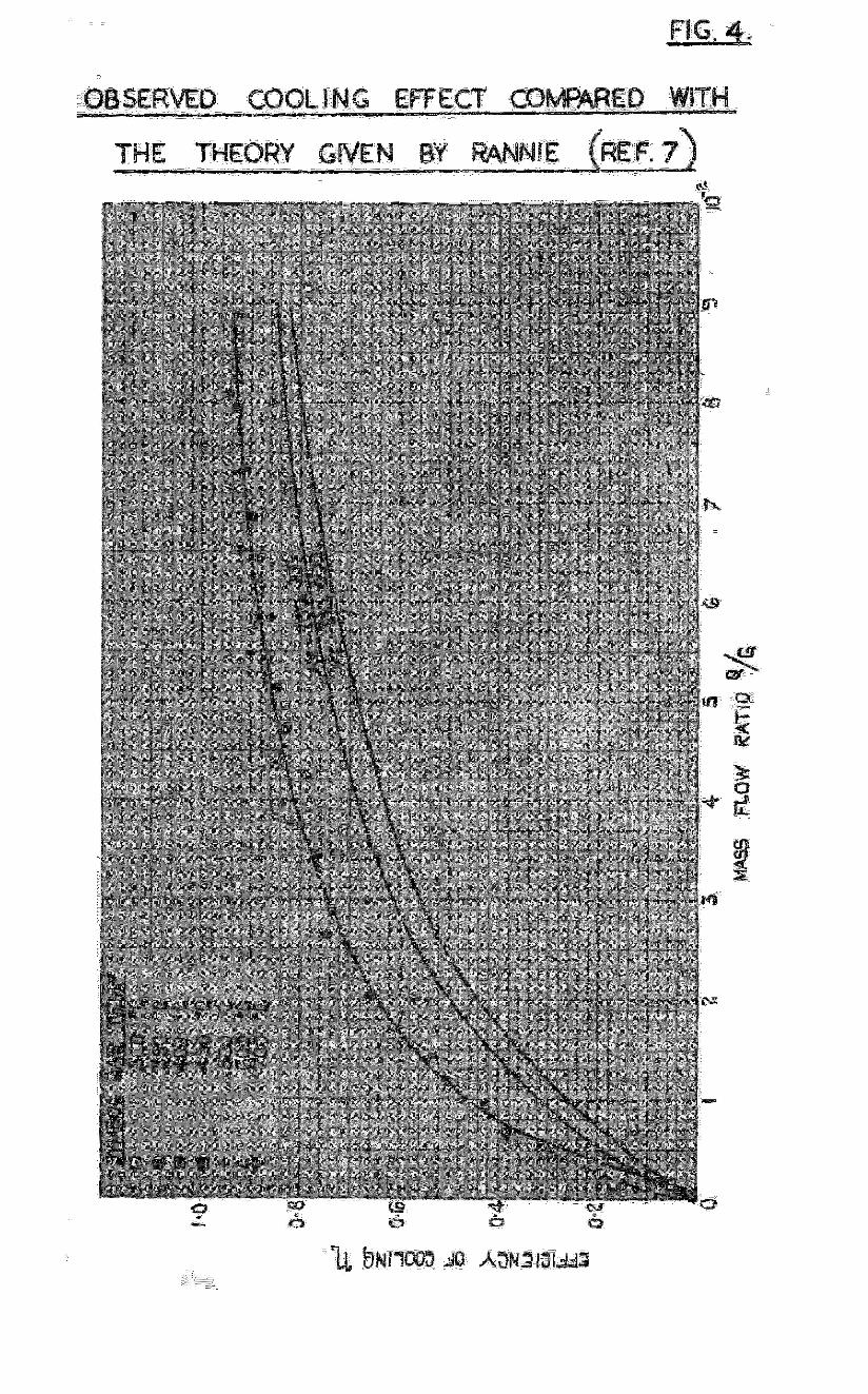
The gas temperatures used in the tests ranged between 300 and 7CO%., while the m3in gas stream Reynolds numbers were between 110,000 and 220,000. Over this range the correlntion suggested by the Authors of reference (6) is quite successful, ns is shown by Figure 4, from which it is apparent how easily cooling efficiencies of the order of 9$ me obtninnble under the conditions of the tests, with quite small air mass flows.
4.2 Analysis and Discussion of the Test Results
Since there is a very large area for hect transfer within the wall of n porous duet, and since the air flows are quite smzll, it is justifinble to assume that in passin:; through the pores, the cooling air temperature is raised to that of the inner surface of the wnll. By nuking this assumption nnd knowing the rate of cooling air flew, it is possible to calculate the heat transfer cocfflcient between the gas streamand the porous duct, but any errors that nre incurred by so doing w-ill be such ns to nuke the coefficients obtained higher than those actually prevniling.
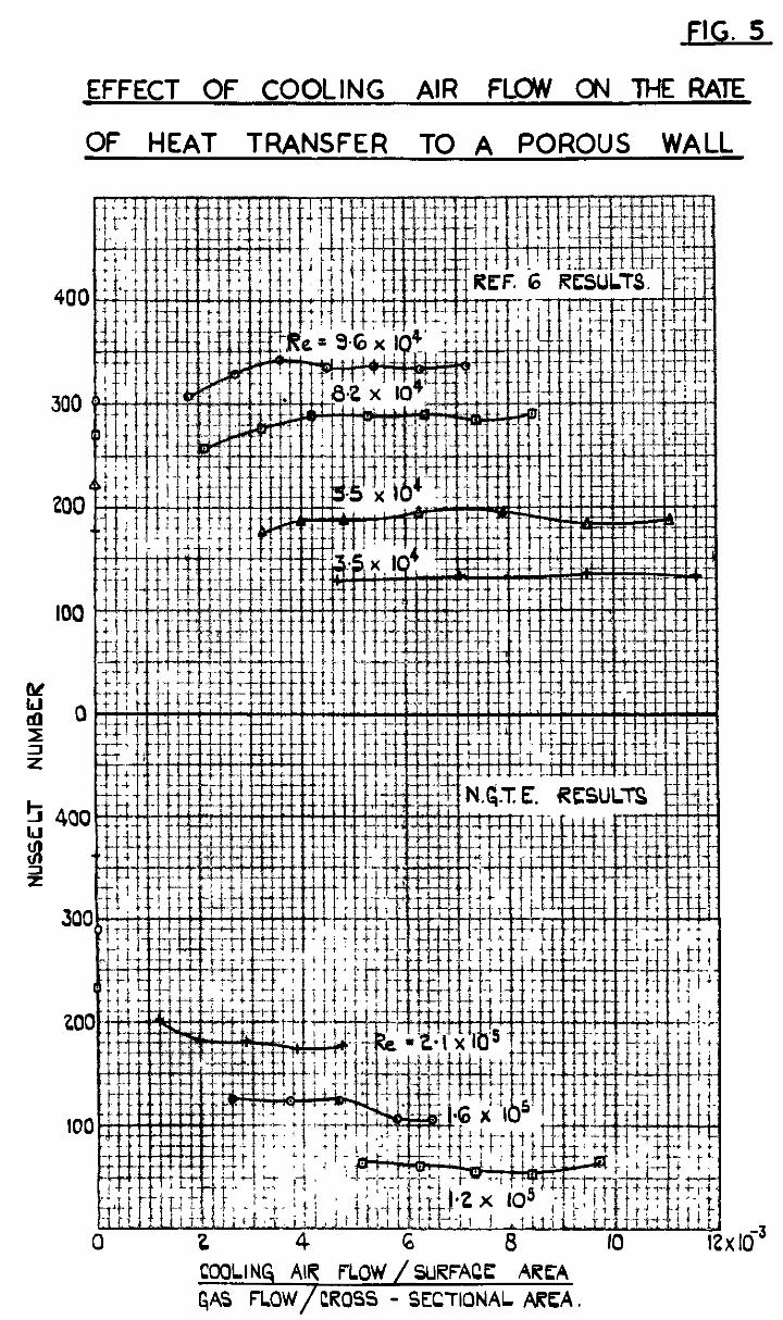
The results obtained with the porous bro.ze duct in the test rig which lms been described, were analysed in this way, and they showed that the Nusselt number, based on the mean of the wall nnd gas temperatures, was !ndependent of the rate of cooling air flaw, and for D. given main 'stream Reynolds number, sensibly constant ot a value considerably less then that IThhich would be predicted for aimilnr conditions of developed turbulent flow. At&y&s of the tests of reference (6) yielded D simihr result, as is shown by ?igure 5, but the reduction in Nusselt number is not so marked, and in fnct, at the higher e Reynolds numbers is negative due probably to the extension of entry length flow conditions to include that port of the wall in which wee inserted the single thermocouple used to meoeure the cooled surface temperature.
Now with the nssumption that the cooling air flow of Q lb/sec.ft.2 is raise6 to the inner wall temperature we hove thnt the heat input to the wnll is:-
Hi' z2 Q.Cp (0,' - T,)
where Hi ' is the heat flow per unit inner wall surface area. But also we have that:-
Hi' = hg (T@; - ew' )
From these trio equations we get:-
I!; s y
= K5 (say)
But by definition the cooli% efficiency, n, is given by
c K5 K5 + 1
. . . . . . . . . . (13)
- 13 -
Report No. R.lO1
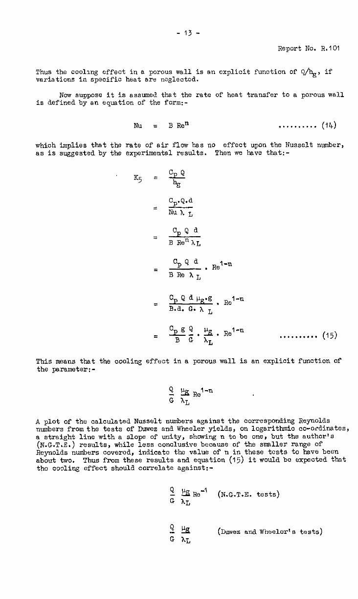
Thus varia
the cooling effect in a porous wall is sn explicit function of QJhg, if .tions in specific heat are neglected.
Now suppose it is assumed that the rate of heat transfer to .e porous wall is defined by sn equation of the forw-
Nu = B Re" . . . . . . . . . . (14)
which implies that the rate of air flow has no effect upon the Nusselt number, as is suggested by the experimental results. Then we have that:-
Cp.Q.d =
Nu A L
cp Q a = B Re"hL
Cp Q a = . Relen
BRehL
= Cp Q d clg-g , Re~-n
B.d. G. x L
= "P?l.!k. Relen B G XL
This means that the cooliw effect in a porous wall is an explicit function Of
the parameter:-
A plot of the calculated Nusselt numbers against the corresponding Reynolds numbers from the tests of Duwez and Wheeler yields, on logarithmic co-ordinates, a strnight line with a slope of unity, showing n to be one, but the aut'nor's (N.G.T.E.) results, while less conclusive because of the srrPlller range of Reynolds numbers covered, indicate the value of n in these tests to have been about two. Thus from these results and equation (15) it would be expected that the coding effect should correlate against:-
54 !%p.e-’ G XL
(N.G.T.E. tests)
2% (Duwez and Wheeler's tests) G AL
- 14 -
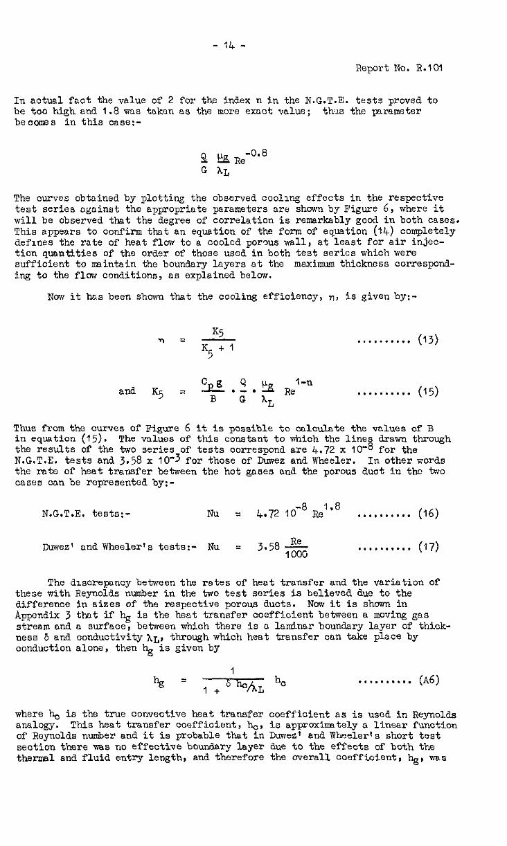
Report No. 8.101
In actual fact the value of 2 for the index n in the N.G.T.E. tests proved to be too high and 1.8 was taken as the more exact value; thus the parameter becomes in this case:-
The ourves obtained by plotting the observed cooling effects in the respective test series against the appropriate parameters are shown by Figure 6, where it will be observed thwt the degree of correlation is remsrksbly good in both cases, This appears to confirm that an equation of the form of equation (14) completely defines the rate of heat flow to a cooled porws wall, at least for air injec- tion qusntities of the order of those used in both test series which were sufficient to maintain the boundary lnyers nt the maximum thickness correspond- ing to the flow conditions, ss explained below.
Now it has been shown that the cooling effioienoy, 7, is given by:-
TI = I<5 KS + 1
. ..I...... (13)
and K5 = Cp .$.!Aa Re'- B G IL
.*........ (15)
Thus from the curves of Figure 6 in equation (15). The values of
it is possible to cdculote the values of B this constant to tiich the lines drawn through
the results of the two series-of tests correspond are 4.72 x 10m8 for the N.G.T.E. tests and 3.58 x 10-J for those of Duwez and Wheeler. In other words the rate of heat transfer between the hot gases and the porous duet in the two cases con be represented by:-
N.G.T.E. tests:- NU = 4.72 IO-' Re"* ..a,...... (16)
Ihnvez' and Wheeler's tests:- Nu q 3.58 $& . . . . . . . . . . (17)
The discrepancy between the retes of heat transfer and the varistion of these with Reynolds number in the two test series is believed due to the difference in sizes of the respective porous ducts. Now it is shcwn in Appendix 3 that if hg is the heat transfer coefficient between s moving gas stream and a surface, between whioh there is n lamitmr boundary layer of thick- ness 6 and conductivity XL, through which heat transfer con take place by conduction alone, then hg is given by
hg = r+blh3~L hc . . . . . . . . . . (~6)
where b is the true convective heat transfer coefficient ns is used in Reynol&q analogy. This heat transfer coefficient, b, is apprcxinately s linear funotton of Reynolds number and it is probable that in Dwrez' and Wheeler's short test section there vias no effective boundary layer due to the effects of both the therms1 and fluid entry length, and therefore the overall coefficient, hg, was
- 15 -
Report No. R.lO1
virtually equal to ho. In the IOn,: porous duct use13 by the author, however, in which developed turbulent flow conditions prevailed, it is believed that the 1nJOCtiOn Of the cooling air led to the formation of a relatively thick boun&ry layer, the equilibrium thlckncss of which was a function of the gas stream Reynolds number alone, and it is the nature of this function that determines the wnner of variation of h , and therefore ?f the Nusselt number, with the Reynoldi; number, Although no qua 9. ltative values of ho and 6 are available, if the term 6 ~/AL is large compared with unity, for the observed variation of Nusselt number with Reynolds number, as given by equation (16), to be correct wo~&J require that the boundary layer thickness in a sW?at cooled duct is inversely proportional to the 1.8 power of the Reynolds number under oonditions of developed turbulent flow.
The foregoing analysis of the sweat cooling process has, of necessity, been somewhat empirical because of the complexities of the transfer processes Involved. There have been, however, sevcral theories of sweat cooling published, all of which involved certain simplifying assumptions. Rannie, in reference (7) for example, has developed a theory of porous wall cooling which assumes that the laminar boundary layer thickness is the same over a sweat cooled wall as for flow through an ordinary pipe, The results of this theory are shown on Figure 4, in which the predicted cooling effects are considerably less than those observed in the tests msde by the author and described in this report, and this &L8cre- panty appears to confirm that the Injection of the air through the wall under developed turbulent flow conditions does result in an appreciable thickening of the laminar boundary layer.
Grootenhuin and Moore in reference (8) give a theory which they have developed by solving, by an approximate method , the fundamental equations of fluid motion with the boundary conditions appropdnte to flow over a porous flat plate through which air is injected. It will be noted that these authors use the parameter (Va/Vg)z Re to correlate their calculated cooling effects, which is equivalent to (Va/Vg)JRe. This parameter is equal to the parameter given by equation (15) with n = 0.5 for the isothermal case and the value of one half for n corresponds to the theoretical figure for laminar flow over a plate, which is the condition assumed by the authors. In reference (9) Grootenhuis and Moore have compared the v-slucs of sweat cooling effects which their t?.eory predicts, with the experlmencal observation of Duwez and W%celer, and the author, and althoEh their calculated curve takes a fair mean through both sets of results (be%reen which, upon the correlation of this report, there is a large discrepancy) the scatter of the points about the curve, especially in the horizontal direction, is so large as to mke inconclusive any comparison IIlade between the theoretical and experimental values.
4.3 Sweat Cooling in Practice
While the results with the test rigprnriously described may be considered as applicable to sweat cooled walls under conditions of developed turbulent flma, and in which radiation is negligible , these conditions rarely occur in gas turbine combustion systems. They mny, however, be assumed, in certain cases, in turbine inlet sections where there is likely to be a stable boundary layer such as is associated with accelerating flav.
In general, however, the ideal conditions that prevailed in the test rig do not apply in practical problems. In combustion chamber flame tubes in which the highest cooling effects are needed, there is usually the violent swirl used to stabilise the flame, and. often the effects of radiation from the burning fuel to be taken into consideration. After the completion of the tests upon the porous bronze duct which have been discussed, this was operated as a combustion chsmbcr by inserting a flame stabilising baffle at its upstream end through which fuel was injected and burnt within the duct. It was not possible to obtain exact results of quantitative value from the rig under these cond.itiOns9 but the maswements that were mde indicated that about t-80 and C half times 0s
- 16 -
Report No. R.101
much air was required for equal cooling effects as compared with the original tests. This ~-~crease may be regarded as resulting from a lorgcr convective rntc of heat transfer, since the flame within the duct was r,oO~verg luminous, being of the type usually associated with distillate fuels, and radiation could therefore be neglected. Where radiation is likely to be appreciable, its effect may be taken into account by adding the rate of radiant heat transfer to that gi;ep; by equation (15) - or a modification of it to allow for the effect of
- and equating the heat input to that picked up by the air in its Passage through the wall, assuming that its temperature is raised to that of the inner surfnce; i.e.
Nu = 4.72 10w8 RelS8 . . . . . . . . . . (16)
for developed turbulent flow. If the factor of 2.5 is accepted to allow for the effect of swirl as observed in the reported tests on the porous bronze duct when operating as a flame tube, then equation (15) can be modified to:-
Nu = 1.2 lO-7 RelW8 . ...*..... (l&l)
Thus % = 1.2 10-7 RelB8 kf
The heat input by convection, Ho, is thus
H, = hg (Tg - Tw) Pg
By radiation, the heat input H, is given by
as explained in Appendix 2. Q, whichever is required is:
Therefore the heat balance to be solved for T,, or
Hc t H, = F . C . Q'(Tw - Ta) f3 P
. . . . . . . . . . (18)
This method of calculation is, of necessity , only empirical and liable to considerable errors from inexact estimate of the requisite heat transfer coefficients, but it may be used to assess approximately the cooling effects likely to be experienced with porous walls workir~ under conditions similar to those described.
The greatest single difficulty in the way of the universal application of sweat cooling is the lack of a suitable porous metal having the necessary properties of tensile and fatigue strength, ductility, resistance to moderate temperatures and controllable permeability. These requirements are of course formidable, but considerable progress has been made towards overcoming them, and the rewards to be gained from so doing will warrant the effort required. However, the metallurgical problems associated with the technique of sweat cooling are outside the scope of this report.
- 17 -
Report No. FL101
4.4 The Pressure Drop in Porous Walls
The pressure drop for condltsons of laminar flow through a porous material is given by D'Arcyls equation which is given in reference (10) as:-
QL Y CO =--
P, 2 - PO2 144 2Pop
P, and PO are the air pressures in lb/ft.2 on either and y is the coefficient of permeability qnd bs the usually square inches. Where turbulent flow occurs,
. . . . . . . . . . (19)
side of the porous wall dimensions of .an area, (n9 exaot criterion for
the point of transition appears to have been decided), a more complicated and general equation by Rose in reference (11) should strictly be used, but it nil1 be found that for most gas turbine applications of sneat cooling D'Arcy's equation applies with sufficient accuracy. For smnll pressure dlff'crences this equation rrny be simplified to:-
. . . . . ...*. (190)
from which it is apparent that the flow rate is proportional to the pressure drop.
It has been suggested that over long periods of cperotion in industrial atmospheres, the permeability of d porous n&ta1 used for sweat cooling will decrease due to the deposition in the pores of soAid mtter previously suspended in the air. If this were to prove the case , and no successful antidote were found, it would provide a serious obJection to the use of sweat cooling for mny gas turbine applications.
Tests mde to determine the susceptibility of porous metals to blockage by atmospheric deposits have shown conflicting results. Observations of perme- ability nnde upon the porous bronze duct used for the original sweat cooling tests dexribed in this report , showed it to drop off rapidly during the first few hours of operation, after which it became steady nt about 4@ of the original value. titer pressure drop tests upon various sndl porous specimens in, however,- a very oily atmosphere, showed the permeability to drop off more and more rapidly until, finally complete blockage occurred. These and other observations showed that the rate of blockage of a porous ~01‘ depot&d very much upon the nature of the particles suspended in the cooling air , and oiliness in particular was a thing to bo avoided. From 011 the observations, also, 4x0 other important, and general, observations could be drmm. Firstly, that deposits in a porous moterinl can, in most cases, be removed, by an air blast from the downstrenm side, rind secondly, that D comparatively crud0 filter - a thickness of rag was - very effective in the case of the oily atmosphere - is sufficient to remove the offending psrtioles fromthe air stream and to prevent any decrease in perno- nbxlity over long operating periods.
5.0 Cooling: by Localised Air Injection
The object of tilis method of cooling is to reduce the rate of heat transfer to a surface by creating over it a layer of comparatively cool fluid. The ideal of the laminar boundary layer through which heat transfer can take place by conduction, or radiation, only, as was achieved with a porous wall, cannot be nttaincd by injection through orifices of n practical size in an ordinary metal wall. However, by careful choice of injection velocities and. arrangements of the inlet ports , it is possible to form a protective blanket
- 18 -
Report No. R.lO1
of a mixture of cooling sir and hot gas which although moving with the nnin strenm, does restriot the convective rnte of bent transfer to the surface over which it is formed.
The most effective way of creating this "boundary layer", as it is called, although the term does not apply m its strict aerodynamic sense, is to inject the cooling sir through rows of suitnble ports, wronged around the perimeter of the surface to be cooled. The layer thus fc-med moves dovmstream over t'ne vdl of the iluct, "decaying", i.e. increasing in temperature, as it does 80) as a result of CL process of both mass and heat transfer from the nmin hot gns stream.
5.1 Theory of Operation
A theory of the operation of the ideal boundary layer formed by .locolised injeotion of air through rows of ports is given in Appendix 4, but n less rigorous alternative which involves a major simplifying assumption, is better suited to explain the mechanism of the cooling process rind to nnalyso observed experimental results.
Consider an elementary length of the wall to be cooled, distant x from the point of injection, and the hent balance between the heat transferred to that part of the wall and that conducted along it becomes:-
hL ' f.dx(eL'OJ q -h,.tJ.f (a (z (4y + 2 5 x) - 3 . . (20)
f is, in this cnse, the perimeter of the surface. Renrrsnging this equation gives:-
e,-$, = -IQ CL&$! ,........, (2&I)
XT+ * t where K6 =
hL
This is similn: to equation (7) of section 3, but in this instance, to solve equation (2On) on ossumptlon must be nrde ns to the form of the function that OL is of X. Now, if the UBSS flow of oooling air is small cornpored with that of the nnin strenm, it may be assumed that, nfter being initially formed at some temperature, say Tg - AB, which is between the air and gas temperatures, the boundary lnyer will move in the direction of incrensing x with its tempera- turo approaching that of the main gas stream. It is suggested by the form of the genersl solution of the ideal boundary layer given in Appendix 4 that the temperature distribution along the duct follws an exponential law, and the simplest possible equation of this form satisfies the conditions assumed above i.e.
~JL = Tg - Atl e-= . . . . . . . . . . (21)
The use of this equation in which OL is assumed constant, to solve equation (2On) represents the maJor simplifyin : assumption that was mentioned previously, but which, however, nppears to be justified by the experimental results 8s shown later.
The value of the boundary layer temperature at a equation (21) nay now be substituted into equation (2Ca to give:- 7
-point, 8L, ns given by
Tk3 - Ae.e-OCX - ow P . . . . . . . . (22)
- 19 -
Report No. R.lO1
which may be integrated to:-
Te- p, e = A3e xm + A40 -=m + AOe - “X
0 I -Kg=*
. . . . . (23)
A3 and 44 are the constants of integration to be calculated from tb.e end conditions.
5.2 An Experimental Investigation
The method of .wall cooling under discussion in this section was the subject of an experimental investigation undertaken by the author. The test rig shown in Figure 3 and described in the previous section was used. The porous duct was replaced by one rolled from 22 S.W.G. stainless steel sheet in which were formed the different injection port arrangements to be tested. Wall temperature measurements for various conditions of air and gas flow mere nnde with thermocouples which were welded to the test section, beneath the lagging with which it was surrounded to reduce external heat losses from the wsll to the incoming cooling air.
There is an infinity of shapes and sizes of injection ports which could be used, all producing their different cooling effects, but in general, an arrangement of holes is the mast convenient to use in gas turbine duoting, and the effect of injection through these was studied in detail. Three separate arrangements were used, all having the same area:-
(1) A single row of l/4 inch holes (Test Series A)
(2) A double row of l/8 inch holes (Series D)
(3) Four rows of l/16 inch holes (Series F)
All the holes were pitched oircumferentially, (2) and (3), axially as well, two diameters apart. ems used; the holes in adjacent rows were staggered
and in the arrangements Where more than one row with respect to one another,
so ns to form a complete injection ring around the circumference.
The additional arrangement for,achieving boundary layer cooling, which suggests itself for application to combustion &amber flame tubes in Rerticulnr, is that in which the air is injected axially through an annulus. It was not foun=J. possible, however, to maintain an annulus of accurately known dimensions during the tests because of thermal distortion, but it was lcnownt and is in fnot obvious, that the air injection velocity should equal that of the snin gas strenm for the optimum cooling effect, and it was felt that the data upon boundary layer decay rates obtained from the tests with injection through holes were applicable with sufficient accuracy to the annular injection case.
5.3 Analysis of the Test Results
The form of the wall te!q?erature distribution associated with boundary layer cooling by localised rodiol air injection is shown by Figure 7. It will be seen how the temperntwe rises rapidly immediately nfter the injection axis, the rate of increase falling off, however, until at n corrrp?rutively short distrnoe dopmstreom, the tempernture is rising very nlcwly along the duct.
- 20 -
Report No. Ii.101
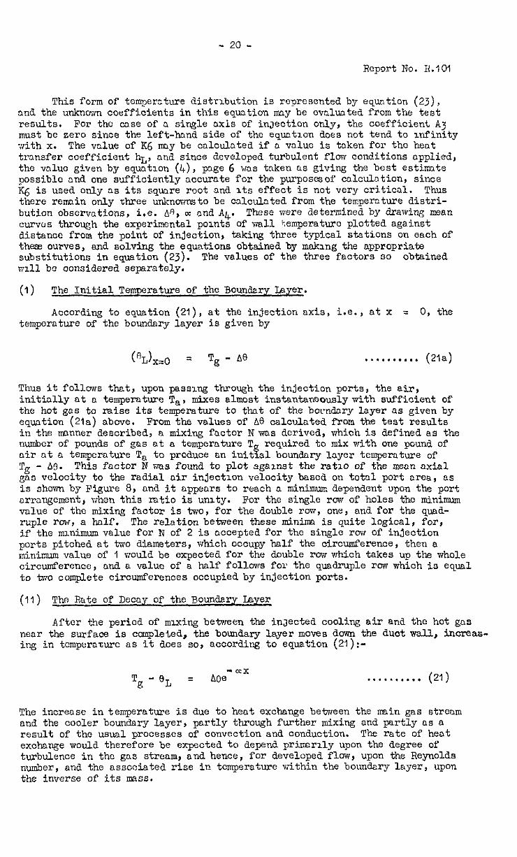
This form of temperature distribution is represented by equation (2J), and. the unknown coefficients in this equation any be evaluated from the test results. For the case of a single oxis of injection only, the coefficient A3 must be zero since the left-hand side of the equation does not tend to infinity with x. The value of KG any be calculated if a value is taken for tho hen+. transfer coefficient hI,, and since developed turbulent flow conditions applied, the vnluc given by equation (L+), p3ge 6 was taken as giving the best estinnte possible and one sufficiently occur-ate for the purposesof cnlculntion, since I(6 is used only as its square root and its effect is not very critical. Thus there remain only three unknovmto be cnlculated from the tempernture distri- bution observations, i.e. As, cc and A&. These were determined by drawing mean curves through the experimental points of wall tiemperaturc plotted against distance from the point of injection, taking three typical stations on each of thess curves, and solving the equations obtained by maklng the appropriate substitutions in equation (23). The values of the three factors so obtained will be considered separately.
(1) The Initial Temperature of the Boundary Layer.
According to equation (21), at the injection axis, i.e., at x = 0, the temperature of the boundary layer is given by
(@L)~,~ = Tg - A0 . . . . . . . . . . (21a)
Thus it follows that, upon passing through the injection ports, the air, initially at a temperature Tar mixes almost instantaneouslywith sufficient of the hot gas to raise its temperature to that of the bocndary layer as given by equation (21a) above. From the values of be calculated from the test results in the nmnner described, a mixing factor N was derived, which is defined as the number of pounds of gas at a temperature T required to mix with one pound air nt a temperature Ta to produce an iuittal boundary layer temperature of
of
To - AC). This factor N was found to plot against the ratio of the mean axial ggs velocity to the radial air injection velocity based on total port area, as is shown by Figure 8, and it appears to reach a minimum dependent upon the port arrangement, when this ntio is unity. For the single roe of holes the mininmm value of the mixing factor is two, for the double row, one, and for the quad- ruple row, a half. The relation between these minima is quite logical, for, if the minimum value for N of 2 is nccepted for the single row of injection ports pitched at two diameters, which occupy half the circumference, then a minimum value of 1 would be expected for the double row which takes up the whole circumference, and a value of a half follows for the quadruple row which is equal to two complete circumferences occupied by injection ports.
(11) The Rate of Decay of the Boundary Layer
After the period of mixing between the inJected cooling air and the hot gas near the surface is ccmgG4,ed, the boundary layer moves dovm the duct wall, increas- ing in tcmperazure as it does so, according to equation (21):-
Tg-BL = hoe- Ozx . . . . . . . . . . (21)
The increase in temperature is due to heat exchange between the rnnin gas stream and the cooler boundary layer, partly through further mixing and partly as a result of the usual processes of convection and conduction. The rate of heat exchange would therefore be expected to depend prinerily upon the degree of turbulence in the gas stream, and hence, for developed flow, upon the Reynolds number, and the associated rise in temperature within the boundary layer, upon the inverse of its mzss.
- 21 -
Report No. R.lO1
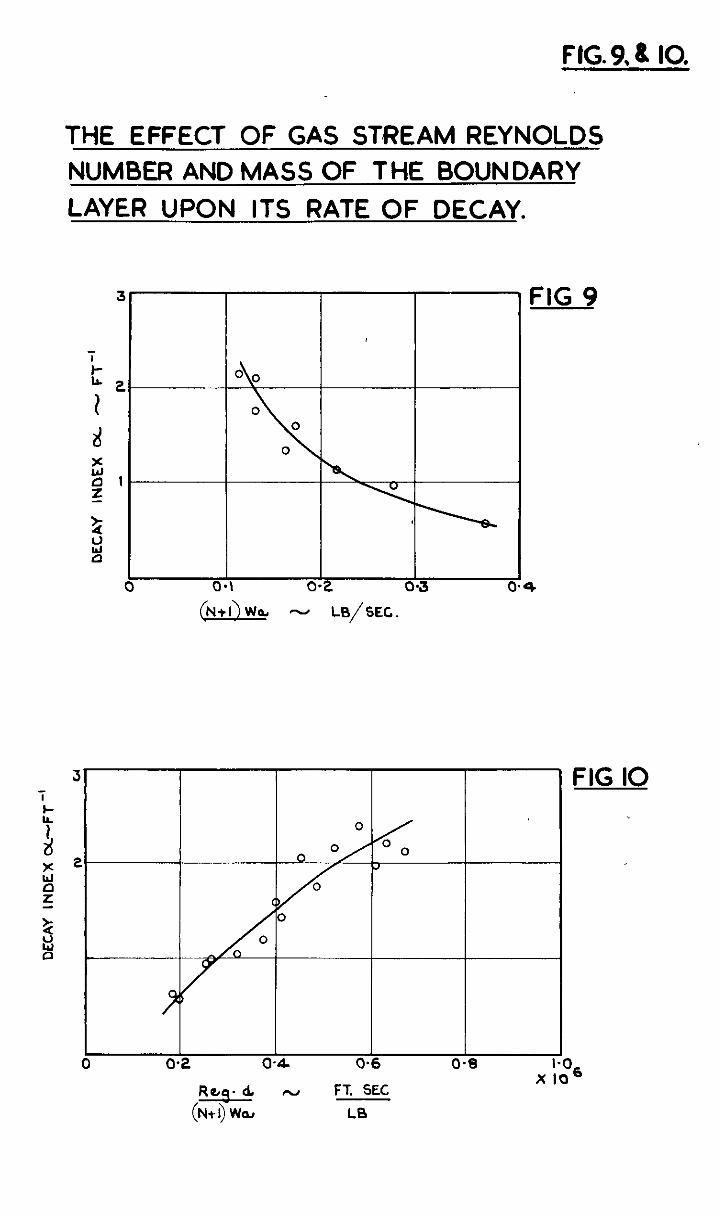
These expectations ore to some extent confirmed by the experimental results. Figure 9 shows the variation of the exponential index OC, which is a measure of the rate of decay, with the IMSS of the boundary layer at D. suhstnn- tinily constant Reynolds number. In spite of the scatter, it is found that the mean line through the points is o reciprocal curve, being n straight line with a slope of minus unity when plotted on logarithmic co-ordinates.
mental The results of the laborious colculntions necessary to analyse the experi-
observations mere very sensitive to inaccuracies in wall temperature measurement, and this condition was greatly nngnified in the case of the index p, because of the narrow range of values of this factor which were covered during the tests, due to the limitations in the air flow available to the test rig. However, nn attempt has been nnde to correlate the observed. values of this decay factor with o. parameter Reg.a/(N + l)Wa, and the result of so doing is shown by Figure 10. In spite of the scatter of the points about the mean line, a distinct trend in the results is apparent. The use of this pnrnmeter involves the nssumption about the linear effect of the Reynolds number upon the rate of heot transfer from the gas stream to the boundary layer, nn effect which was observedinthe lost section in connection Prith the sweat cooling results. There is, however, no experlmentol justification for the inclusion of the duct diameter to allow for the effect of surface nren upon the rate of &cay of the boundcry layer which covers it. It appears, however, reasonable to assume as a first approximation c linear variation between the surface area rind the mass of the boundary layer requi-ed to cover it to produce n given cooling effect. It will be found that the range of the parameter Reg.d/(N+,)Wa covered by the experiments reported here includes most gas turbine duct applications, and that the curve of Figure IO gives an indication of the values of the decoy factor to be expected under similar conditions of developed turbulent flow. The general prediction of these decoy factors is subJect to the some limitations and difficulties as those met with when attempts are mnde to estinnte heat transfer coefficients under conditions of undeveloped flow.
(111) The Additional Cooling Effect et the Injection Axis
Figure 7 shows the wall temperature distribution associated with localised air inJection, and upon the same figure has been drawn the curve of boundary layer tzmpernture calculated from the appropriate values of A0 and. the decay index, P. It will be seen that, in addition to the difference marked A, between the gns strenm temperature rind that of the boundary layer at the injection axis, there is a further reduction In wall temperature, B. Now at this point, i.e., ot x = 0, the wall temperature is given by equation (23) as:-
Tg - ew = A3 + A4 + , _ A@ . . . . . . . . . . w2
(220)
Thus, since in most practical oases K6 oc 2 can be neglected compared with unity without incurring an error of more thnn 2$, A3 + A , or A when there is a single axis of injection only, represents the odds ional 'it' kegree of cooling produced by the heat extraction of the air in flowing through the injection ports. As Figure 7 shows, the effect is a rnp~dly disappearing one, and except when the injection axes ore very close together, since the maximum temperature reached by the wnll is the value of most importonce , it is sufficient for the cnlculation of cooling effects to estimn:e the boundcry layer temperature distribution from the terms A9, i.e., N, and the decay index, cc. The cooling effect ot the axis rexrains of importance, though, since, by it, the structure is kept coolest at the point where it is weakened by the drilling of the inJeotion ports.
- 22 -
Report No. R.lO1
5.4 The Fractical Application of the NetiM of Cooli%
By using a sufficient number of injection axes suitably spaced, any length of wall of a hot gas duct my be cooled by the form&ion of a protective cooled boundary layer, providing that sufficient air is available. The best effect is obtained by initially forming the boundary layer by axial injection of air at the gas stream velocity through an annulus, as may be conveniently formed between the baffle and the flame tube of a combustion ohamber, and then renewing the layer by radial injection through rows of holes where necessary. An injection axis consisting of a double row of holes staggered with respect to one another to form D. complete injection ring is the most suitable orrange- merit, and the hole diameter should be chosen SC that the available air supply gives the requisite injection velocity. In some instances, however, and this is especially the case nt the point of first forming the boundary layer and where axial injection is not easily arranged , it will be necessary to use a quadruple row of holes whereby less mixing, and therefore a oooler boundary lnyer, results than is the case with the double row. Diagrams of a combustion chamber which is intended for long-life operation, the walls of which are maintained at temperatures less than 530% of 75O"C., are given in reference (12).
., with a mean~as outlet temperature Boundary layer cooling as discussed
in this section is used to achieve the low wallkmperatures bf this chamber, a succession of nxial injection stages beiw used for the flame tube, while the outlet seotion in which, as is general , the heat transfer oonditions are less severe, is cooled by a boundary layer formed by radial air injection.
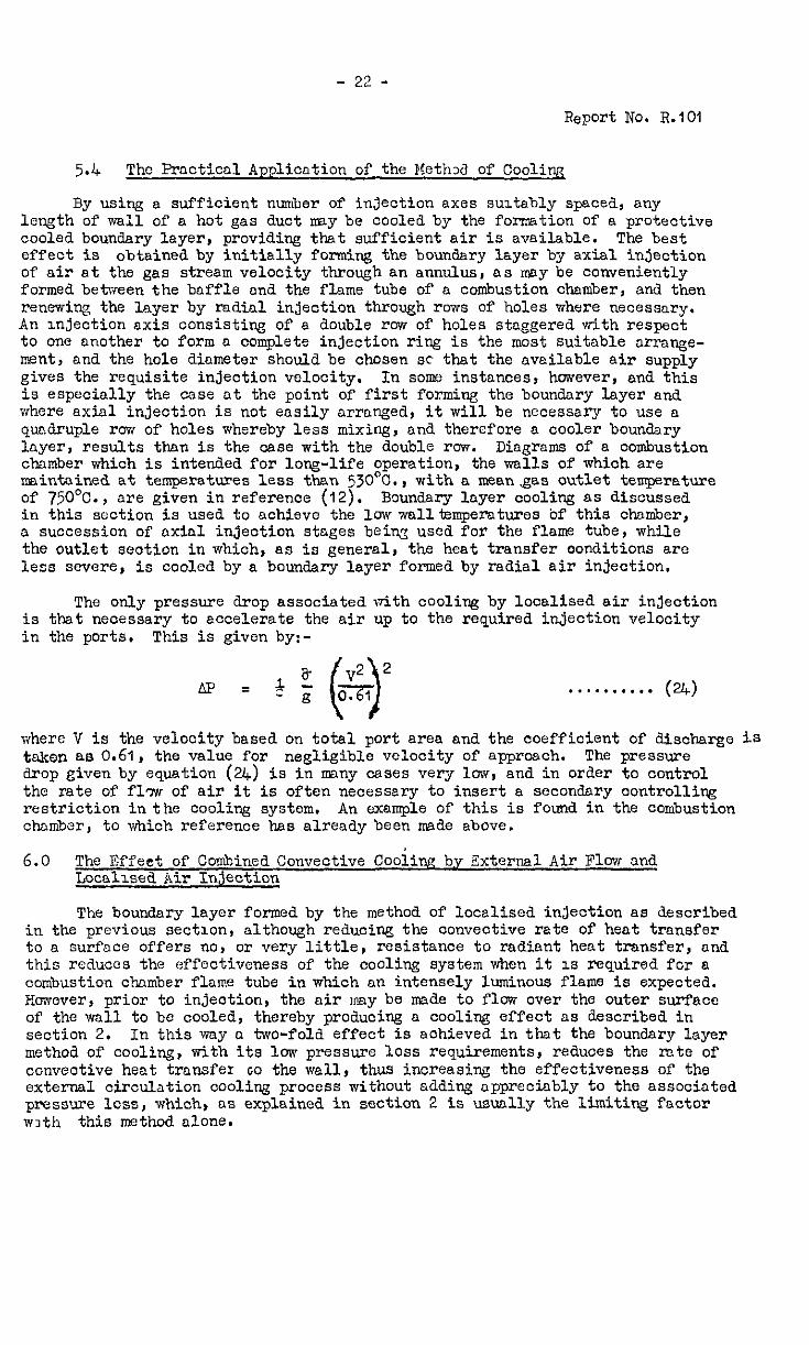
The only pressure drop associated with cooling by localised air injection is that neoessary to accelerate the air up to the required injection velocity in the ports. This is given by:-
AF = 1 a- v* * cg zi
0 . . . . . . . . . . (24)
where V is the velocity based on total port area and the coefficient of discharge is t&on as 0.61, the value for negligible velocity of approach. The pressure drop given by equation (2.4) is in mny cases very low, and in order to control the rate of f17w of air it is often necessary to insert a secondary oontrolling restriction in the cooling system, An example of this is found in the combustion chamber, to which reference has already been meae above.
6.0 The Effeat of Combined Convective Cooiiw by External Air Flow and Locol~sed Air Injection
The boundary layer formed by the method of localised injection as described in the previous section, although reducing the convective rate of heat transfer to a surface offers no, or very little, resistance to radiant heat transfer, and this reduces the effectiveness of the cooling system when it 1s required for a combustion chamber flame tube in which an intensely luminous flame is expected. Hwever, prior to injection, the air ~l?ny be made to flow over the outer surface of the wall to be cooled, thereby producing a cooling effect as described in section 2. In this wiiy o. ho-fold effect is achieved in that the boundary layer method of cooling, with its low pressure loss requirements, reduces the rate of convective heat transfer GO the wall, thus increasing the effectiveness of the external circulation cooling process without adding appreciably to the associated pressure loss, which, as explained in section 2 is usually the limiting factor with this method alone.
- 23 -
Report No. R.lO1
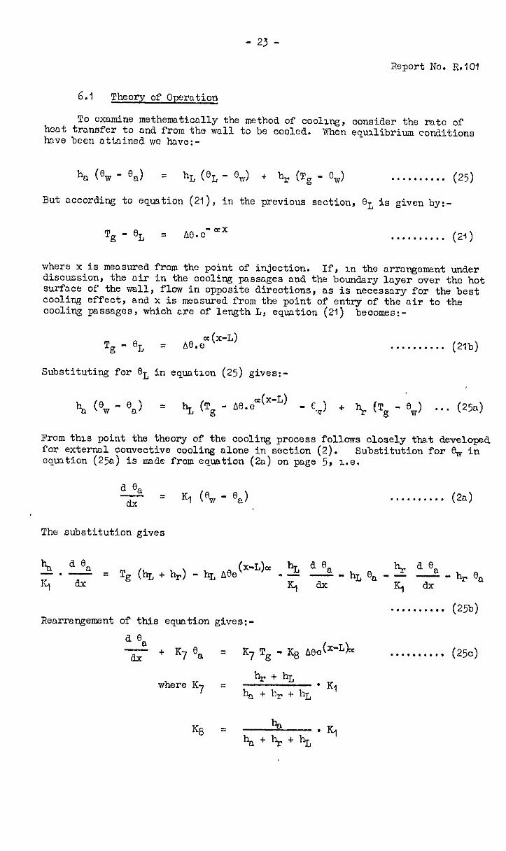
6.1 Theory of Operation
Of To cxnmine methemnticolly the method of coding, consider the rate hcnt transfer to and from the wall to be cooled. have been attnined VIC have:-
But according to equation (21), in the previous section, eL is given by:-
Tg - eL = *e.o- ax . . . . . . . . . . (23)
where x is measured from the point of injection. If, m the arrangement under discussion, the air in the cooling passages rind the boundary layer over the hot surface of the wall, flaw in opposite directions, as is necessary for the best cooling effect, and x is measured from the point of entry of the air to the cooling passnges, which nro of length L, equation (21) becomes:-
From this point the theory of the cooling process follows closely that developed for external convective cooling alone in section (2). Substitution for $r in equation (250) is mde from equation (20) on page 5, I.e.
Renrrengement of this equation gives:- . . ...*.... (25b)
d en xi- + K7 en = x7 Te; - Kg Aee(x’Lb . . . . . . . . . . (25~)
where K h, + hr,
7 q h, + h r + 115 * K’
KS = %I
%l+br+hL l Kl
- 24 -
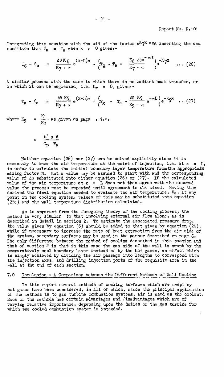
Report No. R.lO1
Integrating this equation with the aid of the factor eK7x and inserting the end conditron that '3a = Ts when x = 0 gives:-
AOK TE - % = K7 + oc e
(x-L)= + (T (@;-Ta-
$3 ABe-OcL) IC7+= )e
-KY ,.. (26)
A similar process with the case in which there is no radiant heat transfer, or in which it can be neglected, i.e. hr = 0, gives:-
Tg - ea = MKV ewe’+ lT _ m K9 K9 + cc lg
T a-Kgtcc
e'aL)e-V . . (27) 1
where $ = 2. as given on page , i.e.
Neither equation (26) nor (27) can be solved explicitly since it is necessary to know the air temperature at the point of injection, i.e. at x = L, in order to calculate the initial boundary layer temperature fromtha appropriate mixing factor N. But a value nay be assumed to start with and the corresponding value of AR substituted into either equation (26) or (27). If the calculated value of the air temperature at x = L does not then agree with the assumed value the process must be repeated until agreement is obt ained. Having thus derived the final equation needed to evaluate the air temperature, es, at any oint in the coolin& system, values of this may be substituted into equation
7.) 250 and the wall temperature distribution calculated.
As is apparent from the foregoing theory of the cooling process, the method is very similar to that involving externsl air flow alone, OS is described in detail in section 2. To estimate the associated pressure drop, the value given by equation (6) should be added to that given by equation (a), while if necessary to increase the rate of heat extraction from the air side of the system, secondary surfaces nay be usea in the manner descrlbea on page 6.. The only difference between the m&hod of cooling described in this section and thst of section 2 is that in this case the gas side of the wall is swept bjr the comparatively cool boundary layer instead of by the hot gases, an effect which is simply achieved by dividing the air passage into lengths to correspond with the injection axes, and drilling injection ports of the requisite ares in the v&l at the end of each section.
7.0 Conclusion - A Comparison between the Different Xethods of Wall Cooling
In this report several methods of cooling surfaces which are swept by hot gases have been considered, in all of which, since the principal application of the methods is to gas turbine combustion systems , air is used as the coolant. Each of the methods has certain advantages and ;isadvsntages which are of varying relative importance, depending upon the duties of the gas turbine for which the cooled combustion system is intcnaed.
- 25 -
Report No. R.lO1
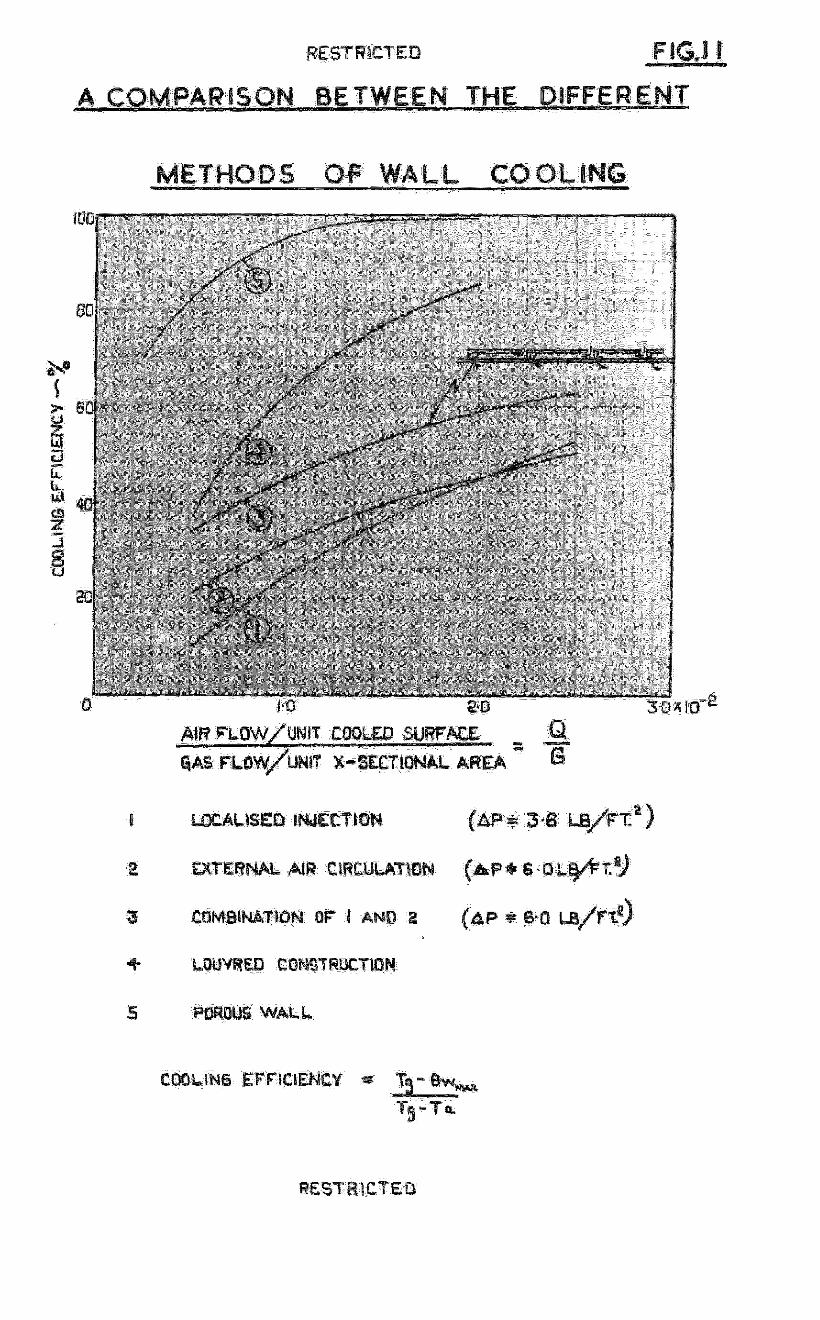
A comparison beteeen the different methods of cooling which have been discussed is made by Figure 11. which shows the results of some calculations undertaken to assess the cooling effects possible in n typical, but hypotheti- cal, hot gas duct, the walls of which were cooled by vnrying air flows used in each of the methods described.
It is nppwent from Figure 11. that by far the most efficient and effeo- kive of these mcthodn is sweat cooling, which uses the porous wall with its large area for he3t extraction and which produces, in certain instances, the additional effect of a reduction in heat transfer to the cooled surface by virtue of a thickening of the lamirmr boundzry layer, through which heat can pass by conduation alone. The uniform distribution of coolant and cooling effect associated with sweat cooling make it, thermodynamically, the ideal method, since no cooling effect is wasted by maintaining one point of the surface at some excessively low temperature in order that 3 second shall not exceed its allowable maximum. This factor, coupled with the effect of the barge internal surfnce area which nnkes resistnncc to heat flow on the air side negligible, nmintains swat cooling as still the most effective method even when the hot gas flow conditions , OS in the entry lengths associated with nbrupt discontinuities in flow, are such that no appreciable reduction in the rcte of heat transfer to the wall is mused by the inJcction of the cooling ail-.
Unfortunately full odvnntage of the merits of sweat cooling cannot yet be taken, because the porous metals cormn?rcially available all need cooling to temperatures which are, in engines which include n high effloiency heat exchanger, lower than those prevailing at entry to the combustion system. As was pointed out in section 4, however , the advantages to be gained from the nvnilnbillty of a porous material having properties suitable for gas turbine ductlng warrant any metallurgical effort required in its development, because the need'f'or such an effective and efficient means of VCA~~ cooling will become increasingly urgent as combustion chamber outlet temperatures increase, and thus make less air available for wall cooling.
For reasons similar to those given in explaining the effectiveness of -went cooling, the louvred wall supplies the second most efficient method of those considered. It falls short of swat cooling with no "blnnkcting" effect only beoausc it is not practicable to construct a louvred surface containing AS mny air passages, and hence as large an internal surface, as is found in the truly porous wall. The louvred combustion chamber flame tube, as described by Lubbock in reference (5), is in effect , the result of an attempt to create artificially a porous wall.
The calculations on which Figure 11. is based assumed that the mode of heat transfer from the hot gas to the surface to be cooled was by convection alone, and the erformance curve of the louvred wall given in this figure is, apart from that of the external air flow method alone, as described in section 2, the orJy one which is not lowered by replacing port of the convective by radiant heat transfer. This is because the louvred wall depends for no part of its calculated cooling effect upon a reduotlon in heat transfer by blanketing, and the effectiveness of the cooling method which still results makes the louvred wall particularly suitable for the flame tubes of large 1~ velocity combustion chambers in which the intensely luminous flames associated with the combustion of heavy fuel oils or coal are expected, and wherein radiant heat transfer far outweighs that resulting from convection. The main disadvantage associated with the louvred form of construction - its relatively great weight
-and bulk - any only be of secondary importance in such cases, which are likely to be either nnrine or power station gas turbine applications, in which savings in weqht and space oan be socrifiocd in the interests of reliability.
- 26 -
Report NO. %I01
Each of the rennining three methcds of wall coding, results in non- uniform surface temperature distributions and therefore, since it is the highest temperature ranch& in a system which qust be used ta as8ess the cooling effect, they nre necessarily less efficient than those whichuse either the porous or the louvred ~11. Of the three methods, 8s would be expected, thnt described in section 6. which is a combinat‘lon of the other tiio, is the most effective ond should be used whenever it is necessary to obtain the highest degree of cooling vdth n given air flow rind. allavable pressure drop without resorting to either porous mterinls or the louvre& form of construction. The remining tvro mean8 of wall cooling, those which involve either a controlled external flow of nir, or localised boundary layer injection, produce roughly equal cooling effects , the actud relative values depending u)on the allowable pressure drops in the system. Both require the minimum of comi;lia8tion in constructional arrangements and are especially suited for moderate outlet tempernture combustion systems in which there is o large mns8 flm of air in exce8s of that require& to obtain efficient prtiry zone combustion.
Briefly, reviewme, then the available methods of wall cooling for gos turbine combustion systems a8 described in this report, we have, firstly, svrent cooling, which with the development of 8 suitable pious rmteri.81 would become the universal method. Secondly, there is the heavy ona expensive louvred wall which should only be used ns D. last resort for flame tubes subjected to the most arduous heat transfer conditions in which reli8bility and length of life are of suprome importance. Thirdly, there is the less efficient but still effective cooling method which involves both external air flow sna localisea injection, which can be used to incrense the working life of ordinary t.ypes of combustion system, while either of the remaining two methods, while not capable of high cooline effects, each posse88 the virtue of extreme simplicity. Finally, however, from 8 study of all or any of the cooling system8 which have been described, one conclusion emerges which is almost obvious; that is, that in nny cooling problem, the assoointed difficulties, likethe quantity of coolant required, increase with the size of the surface exposed to the hot gnses, and. therefore it should be the aim of the designer Jf a~ combustion system to keep the area of the walls to an absolute minimum.
The author is indebted to Mr. %'.A. Pennington who was responsible for some of the tests upon which section 5 is based , ana to Mr. P.S. Lamb for assistance with the laborious calculations necessary for the analysis of the results of these tests.
- 27 -
Report No. R.101
N&
1
7 Rannie, D.W.
8
9
IO
11
12
Author Title
Bayley, F.J. "The Cooling of a Hot Gas Duct by Injection of Air at the Wall" N.G.T.E. Re ort No. R.62. January 1990. A.R.C. 13,359. "Notes of %ll Cooling" N.G.T.E. Memorandum 13.90. July 1950. A.R.C. 13,340.
Bayley, F.J.
Smith, A.G.
Lubbock, I.
Duwez, P. and Yfhcoler, A. R.
Grootenhuis, P. l!iOOrC 9 N.D.W.
Grootenhuis, P. Moore, N.P.'?.
XuBkat, 11.
Rose, H.B.
Constant, H. Lloyd, P. and Probert, R.P.
"Heat Flow in the Gas Turbine" J’POC. I.:+ech.E. 1948, V91. 159, W.E.P. No.41.
"The Efficicnoy of Extended Surfaces" Trans. A.S.3T.E. Nov. 191,S. p.621.
"Combustion Problems in the Gas Turbine" Trans. N.E.C.I.E.S. IVY, vol. 67, p.131.
"Cxperimental Study of Cooling by Injeotion of a Fluid Throwh a Porous I,ratorial" J.Inst.Ae.Sc. Vol. I',, No. 9, 1948.
"A Simplified Theory of Porous "'a11 Coolitq" Paper presented at Los Angeles, Fluid $Iechanics. Inst.
June 1948, Quoted in ref. (8)
"Some Observations on the Mechanism of sweat c0011n.S" Proc. Vllth International Congress of Applied l:cchanics, London, 1948.
"Sweat Cooling" 'The Engineer' February 24th, 1950, p.230.
' "The Flow of BomoSeneous Fluids Through Porous Xcdia" The McGraw-Hill Book Co. (N.Y. 1937).
"Fluid Flow Through Beds of Granular Xaterials" Eroc. 1.kiech.E. 1945, Vol. 153, p.141.
Two papers in a Symposium on Internal Combustion Turbines t?oc. 1.iWoh.E. 1950, Vol. 163, w.E.P. ~0.60.
- 28 -
Report No. R-101
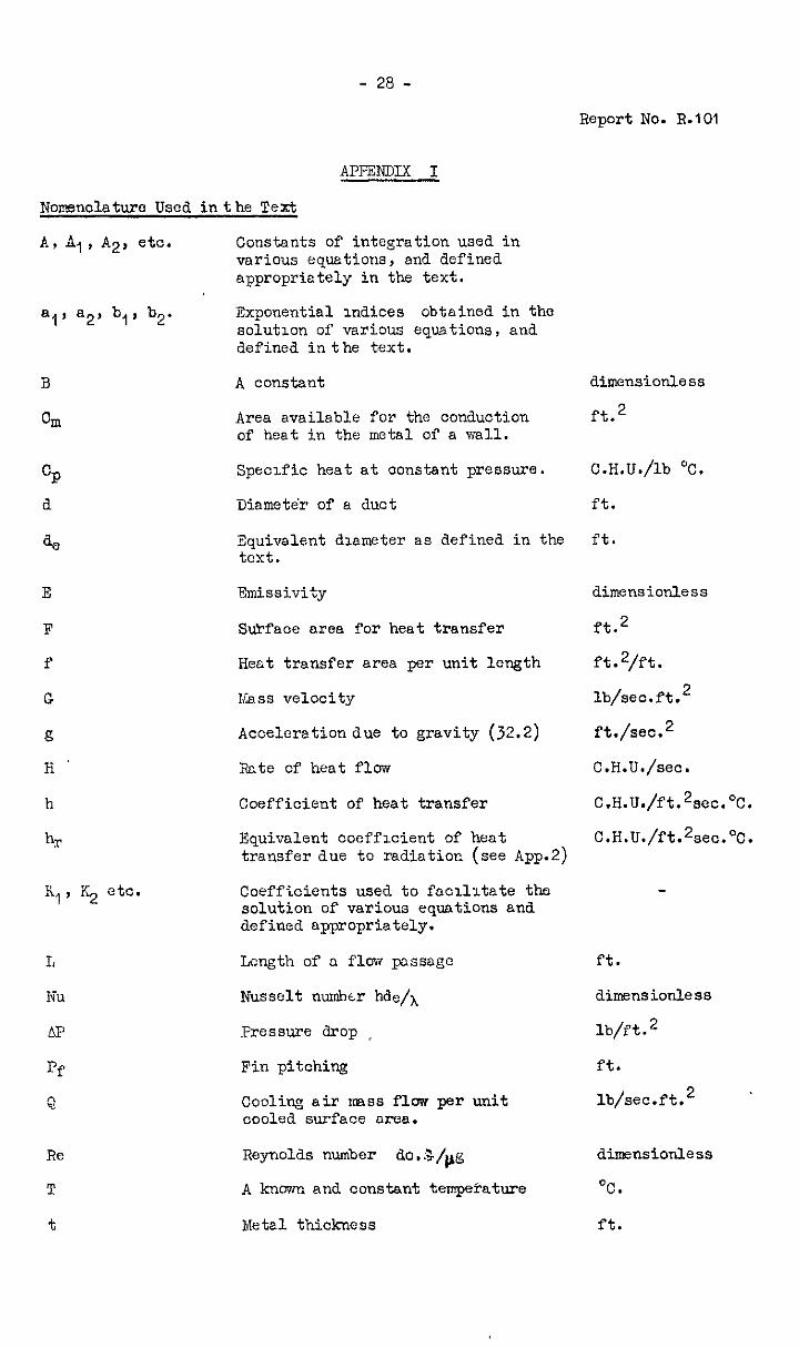
APPENDIX I
Nomenclature Used in the Text
A, Al, A2, etc.
a,' 82' b,, b2.
a
orn
GP d
a,
E
F
f
G
g
H
h
hr
K,, ICC etc.
L
Nu
AP
Pf
a
Re
T
t
Constants of integration used in vnrious equations, and defined appropriately in the text.
Exponential indices obtained in the solutlcn of various equations, and defined in the text.
A constant
Area available for the conduction of heat in the metal of a wall.
Specific heat at constant pressure.
Diamete'r of a duct
Equivalent dlameter as defined in the text.
Emissivity
S&face nrea for heat transfer
Heat transfer area per unit length
ESass velocity
Acceleration due to gravity (32.2)
Rate of heat flow
Coefficient of heat transfer
Equivalent ccefflcient of heat tronsfer due to radinticn (see App.2)
Coefficients used to facllltate the solution of various equations and defined appropriately.
Length of a flow pclssngc
Nusselt numbtr hde/h
Pressure drop ,
Fin pitching
Cooli~ air 111988 flow per unit cooled surface area.
Reynolds number do.5/,,g
A kncwn and constant tempe?atwe
Metal thickness
dimensionless
ft.2
C.H.U./lb 'C!.
ft.
ft.
dimensionless
ft.2
ft.2/ft.
lb/sec.ft.2
ftJsec.2
C.H.U./sec.
C.H.U./ft.2sec.oC.
C.H.U./ft.2sec.oC.
ft.
dimensionless
lb/ft.2
ft.
lb/sec.ft. 2 ’
dirnensicnless
%.
ft.
V
!&
x
Yf
cc
PI, P2
Y
8
0
c-
P
h
b
n
Suffix g
Sut-f1x a
Suffix VI
Suffix L
- 29 - Report No. R.lO1
Velocity
Cooling sir m3ss flow
Distance from an arbitrary origin
F?n height
Exponentid index used as a measure of the rate of decay of n boundary layer.
Constants of integration used in the solution of equation (Ass).
Cocffl'cient of permenbility of G porous wall.
Boundary lnyer thickness
A temperature ot sny point in n system
The temperature difference between the boundary .ss formed initially by locdised sir injection, ana the main gas stream.
Specific vieight
Coefficient of viscosity
Coefficient of thernd conduc- tivity
A parameter used tl define the efficiency of secondary &faces, ona defined in the text.
Cooliw efficiency, defined in the teit.
Refers to the hot gas strcom
Refers to the cooling sir
Refers to the wall being cooled
Refers to the boundary layer nssooi- ated with certain of the cooling methods.
rt/sec.
lb/SW.
ft.
rt.
ft.-'
in. 2
ft.
OC.
OC.
lb/ft.3
lb.-scc./ft2.
C.H.U./ft.sec.%.
dimensionless
aimensionless
- j0 -
Report No. R.101
APPENDIX II
A Note upon Heat Transfer in Combustion Chamber Flame Tubes
St is rarely the csse that the ideal conditions of developea flow to which the standard convection heat transfer equetions strictly n in practice, although often such equstlons, of which equstion (4
ply sre found P , page 6, is
the most commonly used., may be applied without serious error. But in oombus- tion chsmbers the conditions are normally so far removed from the ideal that large inaccuracies m the estirmtes of hent transfer rntes will be inourrea unless corrections are applied to the standard formulae.
The corrections must, of necessity, be emplricnl and the only really accurate way of obtaining values for these is to make heat transfer tests under conditions of flow exactly sidlilar to those which will prevail in practice. Thrs is, in fact, the method of obtaining heat transfer coefficients in flame tubes which is adopted by rranufaoturers who make many combustion chambers of similar design, but :It is not practicable when one or two units only of each type are to be nnde, as for large industrial gas turbine sets or for experimental purposes,and in such cases it is necessary to assess the required correction from previous experience obtained under as near similar oondltions as is possible.
For most combustion cbmber flame tubes it has been found that multiplying the heat transfer coefficient given by equation (4) by a factor of from 2.0 to 2.5 gives a value for the convection heat transfer coefficient between the hot cases and the wall which 1s sufilciently accurate for most wall cooling calculations. This factor may be compared with the value measured when the N.G.T.E. porous duct ms used. as a flame tube. The baffle used to stabilise the flnme in this experiment ems of typical design, and provided. a degree of swirl which is usual for most flame stabilising purposes. Lubbock In reference (5) recommends that equation (4) be used, basiw the Reynolds number on the swirl velocity instead of uuontie mean axial velocity as is usual. This gives a more general correction, provided that the swirl velocity 1s known.
In addi;ion to heat transfer between&e hot gases and the flame tube wall by convection tilere 1s often the effect of radiation to be taken into account. In most combustion chambers burning a distillate fuel such OS kerosene, radiant heat transfer is less than that taking place by convection, and can often be neglected, but when the heaviest of residual fuels is being burned the reverse is often truo.
Now the nett radiant heat exchange between two black bodies at temperatures respectively Tg and TV is ,given by
H = F&- 2.8 x IO-l2 (Tg4 - d+ ) v.....,,.. (Al)
Nav if the two rdisting media nre respectively n gas and the walls which bound it, the equation becomes:-
Ifhere A* is the c.bbsorptivity of tho gas for radiation frcm a surfc~~e &-tempera- ture T,; an?i E&l . 1s a corrected emissivity for the surfncc, us~lly taken as half-way between its true value and unity, which 011~~s for the addxtional opportunity for absorption by the gas of the radiation reflected fromthe walls. Although there is much data svnilable about the emissivity and absorptivity of gases both luminous and non-luminous at pressures substantially atmospheric, there is little or none available about the values at'hlgher pressures such as are found in gas turbine combustion chambers, althcwh it is known that radiant heat interchsngc increases with pressure. In view, therefore, of the uncertnlnty of the values of the gss emissivity and absorptivity under o crating conditions, coupled wxth the difficulty of accurately assessing the gas for mne~ tempcrtl- tures it is not believed thst the use of the complicated equation (A2 is warrant&, rind a simpler alternetive can be used with cqusl confidence:-
H = Fg. 2.8 x IO-l2 EM (Tg4 - Tw4) . . . . . . . . . . 643)
in which B+,, is an equivalent emmissivity for the gases and walls. Values of this are nit known with any accuracy, but it is recommended that to estimte the order of the rate of rsdiant heat transfer, I$( is taken as 0.1 for distillate fuels, such as gas oil, burr&r.? under luminous flame conditions and radiating to normal oxydlsed metal surfaces having an emissivity of aoout 0.8, as 0.2 for the heavier industrial fuel oils such as are burned under boilers, ancl as 0.3 fgr the heaviest rcsidud oils and pulverised coal, which are, h hcnlrcver, not yet oomznercially usd. in gas turbines. .
in order tg convert equation ~2 xnto a more convenlcnt form, USC my be nnde of an equivalent heat transfer ooefflcient, hr, which 1s based upon the temperature difference between the wall and the gas (or flame), and which 1s given by
hr = 2.8 10-12 %F4 - T$
g- w . . . . . . . . . . (AL)
The use of this equation requires ajcncxuledge of T,,, but since the effect of this is much less critical in practical cases than that of Tg, an initial cstimte of the wsll temperature <rhich L s not too greatly in error ~111 enable hr to be calculated, and it may then .be combined with hg, the overall oonvective heat transfer coefficient, unless the cooling system wtioh 1s being used for the wall in question involves the use of a blanketin. layer of air, which offers no resistance to radiant heat flow.
- 32 -
Report No. R-101
APPENDIX III
The rolntion between the overall heat transfer coefficient between s gas and a wall and the Reynolds analogy conveotlon coeffxient
Suppose ho is the coefficient of heat transfer which takes plaae by convection done, with no laminsr conduction effect, between a turbulent gas stream at temperature Tg, and a heat sink, as is assumed in the Reynolds analogy betvreen heat transfer and fluid friction. Suppose that the turbulent gas stream in question is separated from a surface at a temperature e,, by a laminsr boundary layer of thickness 6, which is of temperature 8L at the Surface furthest from the wall. Then the heat flrJw by conduction through the boundary layer is equal to that transferred to it by turbulent convection from the gas stream, i.e.
IL @L - % = ho (Tg - *L) 6
. XL * ew + b.h, T . . BL =
AL + 6.h,
Also the overall rate of heat transfer between the gas stream and the wall, H', is given by:-
H' 2 % (Tg - 0~)
Therefore since this heat flow is equal to that by cxwection to the boundary layer, we have:-
h, (Tg - OL) = hg (Tg - owl
Substitute for BL from equation (A5) ana we get
hc Tg - AL @, + 6 h, TB
hL + 85 '% * b = hg (Tg - 8,)
hc Tg XL - AL % b, = hg CTg - ew) (AL + 6 ho)
whence hc AL = k (AL + 6 h,)
or k = ho
I+%
A Thus if 7 (( 1 we &we ' hg + h,
6h andif
A ,> I we have
hg e ;,
. . . . . . . . . . (~6)
.......... (~6a)
.......... (A6b)
-33 -
Report No. R.lO1
APPENxx IV
A general solution for the temperature distrlbutlon in the ideal boundary layer formed by localised air irqectlon (see Section 6)
Consider the boundary layer as a ccmplete and separate annulus of gas moving uniformly dxxmstream frcm the point of inJectIon. The balance of heat trenderred to and from an elementcry length of It under steady ccntitions is thus:-
hP is the equivalent heat transfer ooefflcient bebeen the gns stream and the b undary layer, and k is the internal diameter of the latter, the case of the cylindrical duct being considered.
Consider now the bnlance between tile heat‘conducted oxially into rind out of the ~a11 covered by the elementary length of the boundary layer, mnd that convected to it: -
Ne have, therefore,
,............... (A8)
Substitutlal in equation (A7) for BL from equation (A8) and rearrange- ment of the terms gives:-
The solution of this equation, which gives the wall temperature at any point x in the system is :-
ew = TE + file bx
+ !32e %i + Pje b3x . . . . . . . . . . (AlO)
where M, 82, @j, are constants of integration end b = roots of the auxiliary equation,
bl, b2, b3 are the
- Cp Wa K6.b 3 - K6 (K.,. t K,,)b2 t CpWa.b t Q, = 0 . . . . . . . . (All)
This equation (All) is a cubic in b and therefore is not capable of direct and general solution. If Kg, KqO and K11 could be calculated a graphical solution or some method of successive approxinmtions might be used to obtain bl, b2 and b3, but the complexities of the heat transfer processes involved sake it impossible to estimate the rate of heat exchange between the main gas stream and the boundary layer, and hence K.,o. Thus to completely solve the equation assooiated with boundary layer cooling it is necessary to make an assumption such as that made in the less rigorous theory of section 6. The solution given by equation (23) and obtained by assuming that the boundary layer te
T rature
equation 21) distribution follows the simple exponential equation -
- compares with the general solution given by equation (AIO), and is identical if:-
-b2 = -Ifi & = -A4
FIG I
EFFICIENCY OF SECONDARY SURFACES
= AVERAGE TEMPERATURE DIFFERENCE OVER FIN AVERAGE TEMPERATURE DIFFERENCE AT BASE
W = FIN HEIGHT - FT.
h = COEFFICIENT OF HEAT TRANSFER - CHU. / FT2SECoC
Am= THERMAL CONDUCTIVITY OF FIN - C.H.U./FT. SEC’C
b = HALF BASE THICKNESS OF FIN - FT.
FIG. 2
THE COOLING EFFECT IN A LOUVRED WALL
GAS TEMPERATURE =75O=t; COOLING AIR TEMPERATURE = 350 -c
FIN DIMENSIONS.- LENQTH IO-’ FT., THICKNESS II/FT., GAP 4 X 10 -3 FT .
2 r’ 450
2 2
400 t
AIR FLOW PER GAP- LB /SEC
FIG. 2b
l-HE TEMPERATURE
THROUGH THE
SYSTEM WITH A
CONSTANT AIR FLOW
DISTANCE ALONO FIN-FT
STATIC PRESSURE POINT STATIC PRESSURE POINT
THERMOCOUPLES THERMOCOUPLES
THERMOCOUPLES THERMOCOUPLES IN POROUS TEST IN POROUS TEST
GAS FLOW FROM GAS FLOW FROM
. - - d---.- .- - d---.-
HACK CHAMBER d UPSTREAM HACK CHAMBER d UPSTREAM
---- ---- SLAGGING SLAGGING
,
- PACHED EXPANSION GLAND - PACHED EXPANSION GLAND
tiff
TEST RIG FOR POROUS WALLED DUCT.
METHOD OF INSTALLING THERMOCOUPLES
S FIG.
EFFECT OF COOLING AIR FLOW ON THE RATE
OF HEAT TRANSFER TO A POROUS WALL
cooLlt4~ AIR FLOW /SURFACE AREA GAS FLOW/CROSS - SECTIONAL AREA.
FIG. 6
AN IMPROVED CORRELATION FOR THE COOLING
EFFECTS IN POROUS-WALLED DUCTS
lDUWEZ&k WHEELER’5 RESUL
2 4 6 8 IO I2
FIG.7
CALCULATE D WILL & BOUNMRY LAYER
TEM PER ATURE DISTRIBUTION CURVES.
-V.---+--g----
FIG. 9, (1 IO.
THE EFFECT OF GAS STREAM REYNOLDS NUMBER AND MASS OF THE BOUNDARY LAYER UPON ITS RATE OF DECAY.
FIG 9
4 (N+I)W.. - LB/SEC.
3 3 FIG FIG IO IO
2 2
I I 0 0 0.2 0.2 0.4 0.4 0.6 0.6 0.0 0.0 I-0 I-0
FT. SEC FT. SEC x IO6 x IO6
(. (. - - LB LB
f
P
C.P. No. 133 (14,648)
A.R.C. Technml Report
CR0 WN COPYRIGHT RESERVED
York House, Km&may, LOMXIN, w.c.2 423 Oxford Street, LONDON. w I P.0 Box 569, Il)NDoN, se.1
13a castle street. BDMBUROH. 2 1 St. Andrew’s Crescent, CARmFF 39 Kmg street, MAN-, 2 Tower Lane, BRLPTOL. I
2 Edmund Street, BIRMINGHAM, 3 80 ChIchester street, BELFAsr or from any Book.ullcr