6
/ CDE ENERGIZING IDEAS CORNELL DUBILi ER Mitigation of Haonics On Low-Voltage Power Systems

/
CDE
ENERGIZING IDEAS
CORNELL
DUBILi ER
Mitigation of Harmonics
On Low-Voltage Power Systems

What are Harmonics?
The term "harmonics" is used today to describe many power system problems. The following details some key concepts in underntanding harmon ic phenomena.
Any periodic wave can be described as a sum of sine waves with varying magnitude and frequency. This is known as a Fourier Series. Each term in the series is referred to as a harmonic of the fundamental frequency. In power systems, the fundamental frequency is 60 Hz. and the harmonics are integer multiples of 60 Hz. ( 180, 300, 420, etc.) Funher, these waves are symmetrical about the vertical axis. One wave form that appears repeatedly in the analysis of harmonics is the square wave. Many harmonic producing loads generate voltage or current wave forms that can be closely matched with a square wave. These devices range from rectifiers to arc furnaces. The figure below illustrates a square wave in both the time and frequency domain.
Figure 1
It should be noted that the term "hannonics 11 and "transients" arc often used interchangeably; however, these two terms describe two very distinct phenomena. Harmonics are steady state occurrences while transients are, as the name implies, random. The �ollowing figure illustrates the difference Jetween the two wave forms.
Figure 4
Total Harmonic Distortion (THD) is the quantity that is used to give a general definition of the "quality" of the cUITent and voltage. The greater the value of THD, the more distorted the sine wave. THO 1s defined as follows:
THO-
( V., + V. 2 + ... +V" 2 ) 112
V1
Where, V1. V3, ... V0 = Individual RJ,,fS harmonicVoltage ·Components and V1 = Fundamemal
frequency (60 Hz) RMS Vol!age.
Origins of Harmonics on the
Power System
Harmonic distortion results from nonlinear loads in the power system. These non linear loads can be grouped into three major categories.
I. Ferromagnetic Devices2. Electronic Power Converten3. Arcing Devices
Toe most common of these on industrial power systems is electronic power conversion equipment Some examples of this type of equipment are listed below:
Computer Equipment Copy Machines Electronic Ballasts Facsimile Machines Adjustable Speed AC Drives Uninteruptable Power Supplies DC Drives DC Rectifiers
From the IEEE Standard 519, the typical current harmonic spectrum for a three phase 6-pulse convert,r is shown in the following table.
,__. Hannonic Magnitude
s 17.5% 7 11.1% 11 04.5% 13 02.9% 17 01.5% 19 01.0%
Table I
Notice that there are no triplen harmonics present in a three phase connection. Toe typical
2
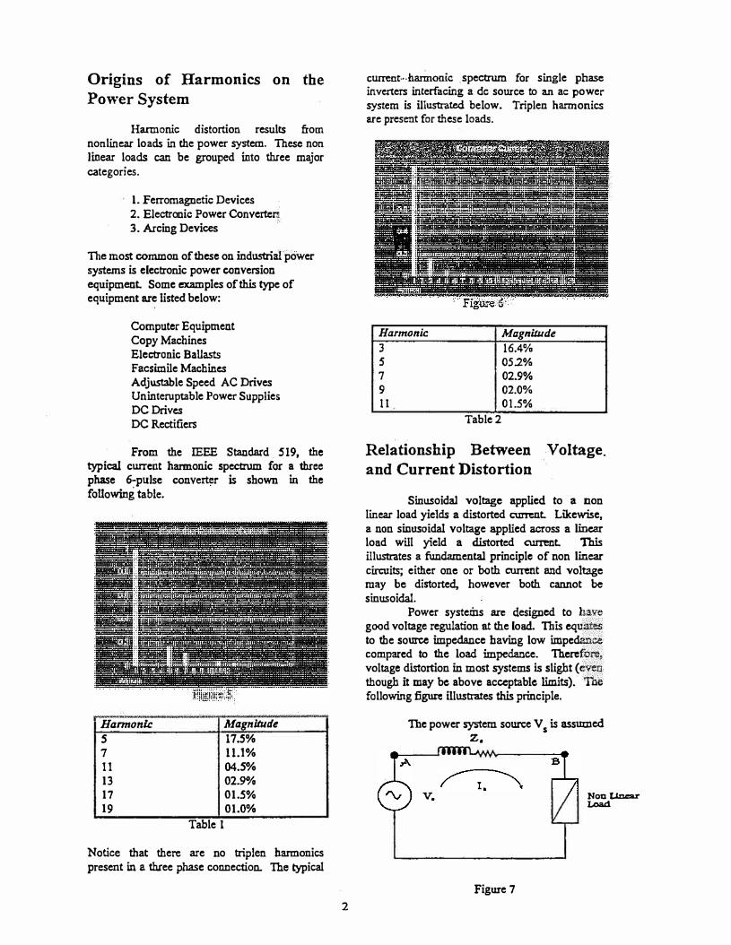
current•·•harmonic spectrum for single phase inverters interfacing a de source to an ac power system is illustrated below. Triplen harmonics are preseot for these loads.
Harmonic Magnitude
3 16.4% s 05.2% 7 02.9% 9 02.0% 11 01.5%
Table 2
Relationship Between Voltage.
and Current Distortion
Sinusoidal voltage applied to a non linear load yields a distorted current Likewise, a non sinusoidal voltage applied across a linear load will yield a distorted current This illustrates a fundamental principle of non linear circuits; either one or both current and voltage may be distorted, however both cannot be sinusoidal.
Power systems arc designed to have good voltage regulation at the load. This equates to the source impedance having low impedance compared to the load impedance. Therefore, voltage distortion in most systems is slight ( Cl'�en. though it may be above acceptable limits). "The following figure illustrates this principle.
Toe power system source V 5
is assumed z.
v.
Figure 7
Non Uncar Load

to be an ideal voltage source (Impedance • O). Therefore there is no voltage distortion at •A". The source supplies power through the distn'bution network represented by the impedance, Z
5• The resulting distorted current
through this impedance causes the voltage to be distorted at "B". The amount of voltage distortion is dependent upon the value of Z and
. d s
current magmtu e. The effects of harmonic producing
loads are greatly dependent upon the power system characteristics. The presence of hannonic producing loads alone is not a definite indication that there will be an adverse effect to the power system or other connected loads.
Effects of Current Distortion
Although harmonic currents may not directly affect other power system loads connected to the system if the voltage distortion is low. they may have a severe effect on power delivery elements connecting these loads to the power system. This is especially true for distribution feeders providing power to single phase harmonic producing loads. The following figure illustrates such a system.
Figure 8
The majority of single phase loads are connected line to neutral. Under conditions where the loads are linear, a balanced three phase load consisting of 60 HZ current, would be delivered by the transformer secondary resulting in insignificant neutral currents. However when these loads are non linear, such as computers or any office equipment which uses a switch mode power supply, the current contains significant amounts of third order harmonic distortion (180 Hz.). These triplen or zero sequence currents add In the neutral. The figure below illustrates this principle. Under balanced conditions, 60 Hz. three phase currents 120° apart equate to zero.
3
However, 180 Hz currents 120° apart are added together.
Fundamental & Third Harmonic
Figure 9
Transformers used in these applications are subjected to severe ·operating conditions which could result in premature failure. Hysteresis, eddy current, and stray losses in the iron core increase dramatically with . harmoaic currents present. Additional heating occurs due to the triplen harmonic current becoming trapped within the delta winding. Further the neutral conductor used in these circuits is normally sized equal to phase conductors in order to meet code requirements which would accommodate worst case conditions for linear loads where one phase is fully loaded and the other two unloaded: Also, no overload protection is provided on the neutral conductor since this protection would normally be provided by the protection on the phase conductors. Toe net result is that the neutral conductor can be signiticandy overloaded and unprotected leading to catastrophic failure. Other effects of zero sequence harmonics include the following:
• High neutral to ground voltage• High peak phase current• High average phase current• High TIID of voltage and
current • Low Power Factor• Telephone Interference• Increased apparatus vibration• Electronic device malfunction
Corrective Solutions
One solution to this problem may be to replace the transformer and neutral conductors with elements which have significandy more· capacity and derate them for use on systems with high current distortion. In some cases this may not be economically feasible; in addition fault

current may increase beyond the ratings of the existing protective devices.
Another solution is to remove the harmonic current from the system. This can be achieved by adding a zero sequence filter. Tuned LC filters have been employed to provide this filtering, however for most 208/120 volt applications, the fundamental current is not displaced adequately to allow for the added capacitance on the system. In other words, the added capacitance of a tuned LC filter would create a leading power factor on the system. Perhaps the solution best suited for this application is a zero sequence filter which operates on the principle of an ideal Zig-Zag auto transformer. These filters provide a high impedance to ·positive and negative sequence currents and an ultra low impedance to zero sequence currents. Caution must be observed when applying these filters. Harmonic curreat flow, fault levels and single phasing performance must all be evaluated.
Effects of Voltage Distortion
As described earlier, harmonic voltages are usually caused by the interaction between harmonic currents and the power system impedance. Under normal conditions, this relationship does not result in significant voltage distortion. However, ' when power factor correction capacitors are applied to a power system where harmonic cUrTents are present, the capacitors and system impedance (inductive) will resonate at a particular frequency. This resonant frequency is dependent upon the amount of capacitance and system inductance. Should this resonant frequency be on or near a harmonic generated by a non linear load, the voltage distortion at that harmonic can be greatly amplified resultiag in significant harmonic distortion. This principle is illustrated in the following example.
z.
v,
Figure 10
B
Noa IJncar Load
4
Figu';-e 11
Voltage - w/ Capacitors
Figure 12
Notice that the system without capacitors results in minimal voltage distortion. However, the same system with the addition of capacitors results in parallel resonance near the fifth harmonic and a significant increase in harmonic distortion is created. Notice the sharp increase in peak voltage.
Harmonic voltage distortion creates harmonic magnetic fluxes within motors. These· fluxes contribute little useful work, increase losses, and create excessive heating. The net effect of these harmonics is premature motor failure.
Power Factor Correction Capacitors are the system component most affected by voltage distortion. Thermal failure is caused by excessive RMS cUrTent through the capacitors. This is due to the declining impedance value of the capacitor as the frequency increases. Insulation failure is caused by excessive peak voltages. These peak voltages can be as high as the arithmetic sum of the harmonics. Generally, voltage distortion will not be high enough to cause capacitor failures unless the system is resonant at a frequency which there is significant harmonic energy. This is normally the fifth or seventh harm�iiic ..
Corrective Solutions
Undesirable harmonic voltage distortion can be prevented by altering the flow of harmonic current into the power system. Toe most co=on approach is to divert these currents with a low impedance shunt path. This path is provided by a shunt filter. These single tuned filters are an economical and reliable

method for solving harmonic distortion problems.
The application of an LC tuned or "notch" filter is to simply short circuit a particular harmonic current. This filter may also be used to move the resonant frequency of the system safely away from a troublesome harmonic. This is useful in instances when a power system is capable of absorbing the harmonic currents produced by a load except when resonance exists. The fundamental approach to the filter design is;
1. Determine the amount of hannonic currentto be filtered and the required harmonicfrequency (lfn, fnl-
2. Select a capacitor size based upon therequired harmonic current to be filteredand the 60 Hz reactive power required(MVAR.Xc).
3. Determine the reactor impedance neededto achieve the desired tuning (Xr).
4. Check the filter response including theeffect of component tolerances.
5. Check the peak and steady state voltageacross the capacitor including the fundamental and harmonic frequencies (V peak• V rrnsl•
The following example illustrates this process given the system in figure 10. The existing capacitor bank is used to safely detune the system resonance away from the fifth.
z.
v.
Figure 13
Non Uc.ear Load
Im edance vs. Fre uen u---���-�---�-�--�
--,J-
......,._
- _______ ,.._..,,._ ... ____ ,_ .. ,_,,. ___
Figure 14
5
Figure 15
Once the filter components are selected and they are checked to insure that they will operate within their ratings, the expected system results are reviewed.
Useful Formula
Resonant Frequency
Filter Design Given Capacitor Size & Filter Frequency
Reactor Impedance
x,_ =
Filter Duty
Total RMS Current {Approximate:}
Fundamental Voltage Across Capacitor
Harmonic Voltage Across Capacitor x.
V =I x-cn fn n
Approximate t'cak Voltage
V peak= �1 + Ven
Approxi"matc RMS Voltage
Yms =J v� + v�
Approximate Reactive Power of Filter
KVAR = 3 x✓-..:: x I:,.


