Volume No: 1(2014), Issue No: 12 (December) December 2014 www.ijmetmr.com Page 862 Abstract: The STATCOM (Synchronous Static Compensator) based on Voltage Source Converter (VSC) is used for voltage regulation in transmission and distribution sys- tems. The STATCOM has emerged as a promising de- vice to provide not only for voltage sag mitigation but a host of other power quality solutions such as voltage stabilization, flicker suppression, power factor correc- tion and harmonic control. However, STATCOMs are limited in their ability to improve the system stability margin due to their restricted capability for delivering real power. The integration of Ultracapacitor energy storage sys- tem (UCESS) into STATCOMs can provide independent real and reactive power absorption/injection into/from the grid, leading to a more economical and/or flexible transmission controller. The aim of this work is to in- vestigate how ultracapacitor based energy storage technology can be used to enhance the capability of STATCOM units to maintain a high quality of distribu- tion voltage, performance voltage sagging in the sys- tem and improve the system stability. Keywords: MATLAB/Simulink, STATCOM, Ultracapacitors, Voltage Source Converter (VSC). I.INTRODUCTION: Quality power supply is essential for proper operation of industrial processes which contain critical and sensi- tive loads. These loads include low-power electronics devices such as process control equipment, computers as well as power electronics-controlled motor drives. M.Deepak M.Tech Student (PS&PE), Department of EEE, NOVA College of Engg and Technology. A Surya Narayana Babu Assistant Professor, Department of EEE, NOVA College Of Engg and Technology. Disturbances such as voltage sags and swells, short du- ration interruptions, harmonics and transients may dis- rupt the processes and lead to considerable economic loss. Among the disturbances, voltage sags are con- sidered to be the most significant and critical. Voltage sag is a momentary decrease of the voltage RMS value with the duration of half a cycle up to many cycles. Volt- age sag can cause serious problem to sensitive loads that use voltage sensitive components such as adjust- able speed drives, process control equipment, and computers. STATCOMs [1],[2] by their own can exchange reactive power with the power system, but they are limited in their ability to improve the system stability margin due to their restricted capability for delivering real power because they don’t include energy storage devices. Recent developments and advances in energy storage and power electronics technologies are making the application of energy storage technologies a viable so- lution for modern power applications. Viable storage technologies include batteries, flywheels, ultracapaci- tors, and superconducting energy storage systems. Some of these energy storage systems have been used with STATCOMs for steady-state voltage control and to enhance the performance of power system The recent development of ultracapacitors provides a new range of devices which can store significant amounts of energy. Their main application is for short term “power boost” type applications where they can release a large amount of energy quickly, and then re- charge, with a smaller current if necessary.The aim of this work is to investigate how ultracapacitor based energy storage technology can be used to enhance the capability of STATCOM units to maintain a high quality of distribution voltage, performance voltage sagging in the system and improve the system stability. ISSN No: 2348-4845 International Journal & Magazine of Engineering, Technology, Management and Research A Peer Reviewed Open Access International Journal Mitigation of Sag in Single and Double Phases Using STATCOM and Ultra capacitor
The STATCOM (Synchronous Static Compensator) based on Voltage Source Converter (VSC) is used for voltage regulation in transmission and distribution sys-tems. The STATCOM has emerged as a promising de-vice to provide not only for voltage sag mitigation but a host of other power quality solutions such as voltage stabilization, flicker suppression, power factor correc-tion and harmonic control. However, STATCOMs are limited in their ability to improve the system stability margin due to their restricted capability for delivering real power.
The integration of Ultracapacitor energy storage sys-tem (UCESS) into STATCOMs can provide independent real and reactive power absorption/injection into/from the grid, leading to a more economical and/or flexible transmission controller. The aim of this work is to in-vestigate how ultracapacitor based energy storage technology can be used to enhance the capability of STATCOM units to maintain a high quality of distribu-tion voltage, performance voltage sagging in the sys-tem and improve the system stability.
Keywords:
MATLAB/Simulink, STATCOM, Ultracapacitors, Voltage Source Converter (VSC).
I.INTRODUCTION:
Quality power supply is essential for proper operation of industrial processes which contain critical and sensi-tive loads. These loads include low-power electronics devices such as process control equipment, computers as well as power electronics-controlled motor drives.
M.DeepakM.Tech Student (PS&PE),
Department of EEE, NOVA College of Engg and Technology.
A Surya Narayana BabuAssistant Professor, Department of EEE,
NOVA College Of Engg and Technology.
Disturbances such as voltage sags and swells, short du-ration interruptions, harmonics and transients may dis-rupt the processes and lead to considerable economic loss. Among the disturbances, voltage sags are con-sidered to be the most significant and critical. Voltage sag is a momentary decrease of the voltage RMS value with the duration of half a cycle up to many cycles. Volt-age sag can cause serious problem to sensitive loads that use voltage sensitive components such as adjust-able speed drives, process control equipment, and computers.
STATCOMs [1],[2] by their own can exchange reactive power with the power system, but they are limited in their ability to improve the system stability margin due to their restricted capability for delivering real power because they don’t include energy storage devices. Recent developments and advances in energy storage and power electronics technologies are making the application of energy storage technologies a viable so-lution for modern power applications. Viable storage technologies include batteries, flywheels, ultracapaci-tors, and superconducting energy storage systems. Some of these energy storage systems have been used with STATCOMs for steady-state voltage control and to enhance the performance of power system
The recent development of ultracapacitors provides a new range of devices which can store significant amounts of energy. Their main application is for short term “power boost” type applications where they can release a large amount of energy quickly, and then re-charge, with a smaller current if necessary.The aim of this work is to investigate how ultracapacitor based energy storage technology can be used to enhance the capability of STATCOM units to maintain a high quality of distribution voltage, performance voltage sagging in the system and improve the system stability.
ISSN No: 2348-4845International Journal & Magazine of Engineering,
Technology, Management and ResearchA Peer Reviewed Open Access International Journal
Mitigation of Sag in Single and Double Phases Using STATCOM and Ultra capacitor
Ultracapacitors (also known as electrochemical capaci-tors, supercapacitors or double layer capacitors) are becoming one of the most interesting solutions due to their electrical nature, which is characterized by high power density, good efficiency and an increasing en-ergy density. Besides, they offer better endurance, reli-ability, high cycling capability, long lifetime and small dimension. Furthermore, operation in a wide temper-ature range is possible, they are more environment-friendly when compared to batteries, and maintenance is not required.
These exhibit high energy density in comparison with conventional capacitors (even when compared to elec-trolytic capacitors) reaching values of thousands of Farads. Nevertheless, their nominal voltage is very low and series connection is required to handle high volt-age levels. Ultracapacitors are constructed similarly to a battery in the sense that two electrodes are im-mersed in an electrolyte with an ion-permeable sepa-rator between the electrodes in order to prevent the electrical contact, but still allow ions from electrolyte to pass through.
The electrodes are made with high effective surface materials, such as porous carbon or carbon aerogel, usually carbon, in order to achieve a larger surface. Charge is stored in those micropores near the interface between the electrode and the electrolyte. The mecha-nism of energy storage is more complex in ultracapaci-tors due to their structure and as a consequence their dynamic response differs in several ways when com-pared to a conventional capacitor.
III.SYSTEM OVERVIEW:
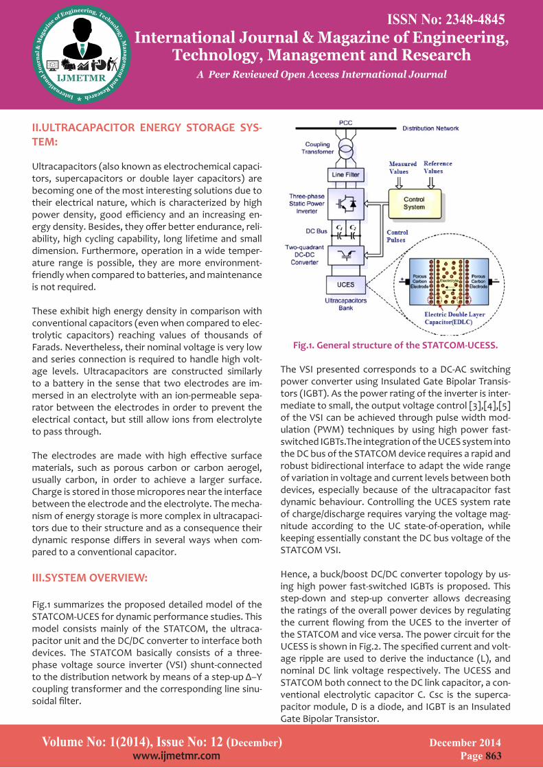
Fig.1 summarizes the proposed detailed model of the STATCOM-UCES for dynamic performance studies. This model consists mainly of the STATCOM, the ultraca-pacitor unit and the DC/DC converter to interface both devices. The STATCOM basically consists of a three-phase voltage source inverter (VSI) shunt-connected to the distribution network by means of a step-up Δ–Y coupling transformer and the corresponding line sinu-soidal filter.
Fig.1. General structure of the STATCOM-UCESS.
The VSI presented corresponds to a DC-AC switching power converter using Insulated Gate Bipolar Transis-tors (IGBT). As the power rating of the inverter is inter-mediate to small, the output voltage control [3],[4],[5] of the VSI can be achieved through pulse width mod-ulation (PWM) techniques by using high power fast-switched IGBTs.The integration of the UCES system into the DC bus of the STATCOM device requires a rapid and robust bidirectional interface to adapt the wide range of variation in voltage and current levels between both devices, especially because of the ultracapacitor fast dynamic behaviour. Controlling the UCES system rate of charge/discharge requires varying the voltage mag-nitude according to the UC state-of-operation, while keeping essentially constant the DC bus voltage of the STATCOM VSI.
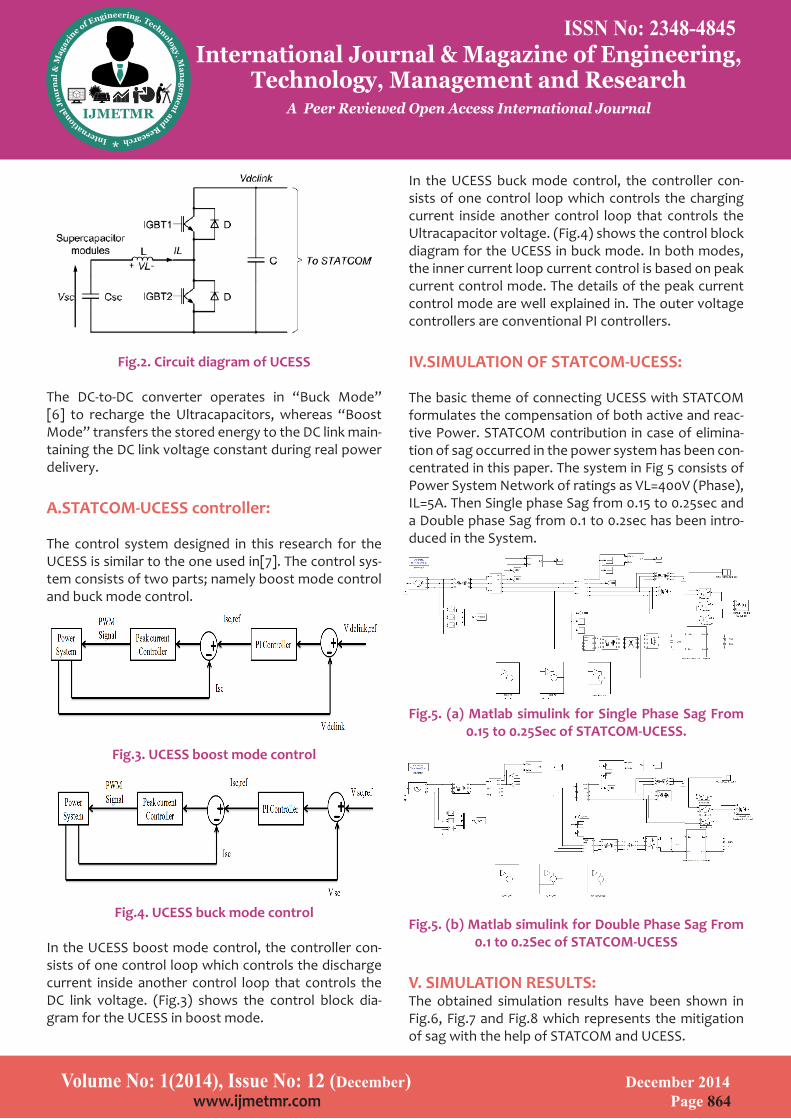
Hence, a buck/boost DC/DC converter topology by us-ing high power fast-switched IGBTs is proposed. This step-down and step-up converter allows decreasing the ratings of the overall power devices by regulating the current flowing from the UCES to the inverter of the STATCOM and vice versa. The power circuit for the UCESS is shown in Fig.2. The specified current and volt-age ripple are used to derive the inductance (L), and nominal DC link voltage respectively. The UCESS and STATCOM both connect to the DC link capacitor, a con-ventional electrolytic capacitor C. Csc is the superca-pacitor module, D is a diode, and IGBT is an Insulated Gate Bipolar Transistor.
ISSN No: 2348-4845International Journal & Magazine of Engineering,
Technology, Management and ResearchA Peer Reviewed Open Access International Journal
The DC-to-DC converter operates in “Buck Mode” [6] to recharge the Ultracapacitors, whereas “Boost Mode” transfers the stored energy to the DC link main-taining the DC link voltage constant during real power delivery.
A.STATCOM-UCESS controller:
The control system designed in this research for the UCESS is similar to the one used in[7]. The control sys-tem consists of two parts; namely boost mode control and buck mode control.
Fig.3. UCESS boost mode control
Fig.4. UCESS buck mode control
In the UCESS boost mode control, the controller con-sists of one control loop which controls the discharge current inside another control loop that controls the DC link voltage. (Fig.3) shows the control block dia-gram for the UCESS in boost mode.
In the UCESS buck mode control, the controller con-sists of one control loop which controls the charging current inside another control loop that controls the Ultracapacitor voltage. (Fig.4) shows the control block diagram for the UCESS in buck mode. In both modes, the inner current loop current control is based on peak current control mode. The details of the peak current control mode are well explained in. The outer voltage controllers are conventional PI controllers.
IV.SIMULATION OF STATCOM-UCESS:
The basic theme of connecting UCESS with STATCOM formulates the compensation of both active and reac-tive Power. STATCOM contribution in case of elimina-tion of sag occurred in the power system has been con-centrated in this paper. The system in Fig 5 consists of Power System Network of ratings as VL=400V (Phase), IL=5A. Then Single phase Sag from 0.15 to 0.25sec and a Double phase Sag from 0.1 to 0.2sec has been intro-duced in the System.
Fig.5. (a) Matlab simulink for Single Phase Sag From 0.15 to 0.25Sec of STATCOM-UCESS.
Fig.5. (b) Matlab simulink for Double Phase Sag From 0.1 to 0.2Sec of STATCOM-UCESS
V. SIMULATION RESULTS:The obtained simulation results have been shown in Fig.6, Fig.7 and Fig.8 which represents the mitigation of sag with the help of STATCOM and UCESS.
ISSN No: 2348-4845International Journal & Magazine of Engineering,
Technology, Management and ResearchA Peer Reviewed Open Access International Journal
Ultracapacitors (also known as electrochemical capaci-tors, supercapacitors or double layer capacitors) are becoming one of the most interesting solutions due to their electrical nature, which is characterized by high power density, good efficiency and an increasing en-ergy density. Besides, they offer better endurance, reli-ability, high cycling capability, long lifetime and small dimension. Furthermore, operation in a wide temper-ature range is possible, they are more environment-friendly when compared to batteries, and maintenance is not required.
These exhibit high energy density in comparison with conventional capacitors (even when compared to elec-trolytic capacitors) reaching values of thousands of Farads. Nevertheless, their nominal voltage is very low and series connection is required to handle high volt-age levels. Ultracapacitors are constructed similarly to a battery in the sense that two electrodes are im-mersed in an electrolyte with an ion-permeable sepa-rator between the electrodes in order to prevent the electrical contact, but still allow ions from electrolyte to pass through.
The electrodes are made with high effective surface materials, such as porous carbon or carbon aerogel, usually carbon, in order to achieve a larger surface. Charge is stored in those micropores near the interface between the electrode and the electrolyte. The mecha-nism of energy storage is more complex in ultracapaci-tors due to their structure and as a consequence their dynamic response differs in several ways when com-pared to a conventional capacitor.
III.SYSTEM OVERVIEW:
Fig.1 summarizes the proposed detailed model of the STATCOM-UCES for dynamic performance studies. This model consists mainly of the STATCOM, the ultraca-pacitor unit and the DC/DC converter to interface both devices. The STATCOM basically consists of a three-phase voltage source inverter (VSI) shunt-connected to the distribution network by means of a step-up Δ–Y coupling transformer and the corresponding line sinu-soidal filter.
Fig.1. General structure of the STATCOM-UCESS.
The VSI presented corresponds to a DC-AC switching power converter using Insulated Gate Bipolar Transis-tors (IGBT). As the power rating of the inverter is inter-mediate to small, the output voltage control [3],[4],[5] of the VSI can be achieved through pulse width mod-ulation (PWM) techniques by using high power fast-switched IGBTs.The integration of the UCES system into the DC bus of the STATCOM device requires a rapid and robust bidirectional interface to adapt the wide range of variation in voltage and current levels between both devices, especially because of the ultracapacitor fast dynamic behaviour. Controlling the UCES system rate of charge/discharge requires varying the voltage mag-nitude according to the UC state-of-operation, while keeping essentially constant the DC bus voltage of the STATCOM VSI.
Hence, a buck/boost DC/DC converter topology by us-ing high power fast-switched IGBTs is proposed. This step-down and step-up converter allows decreasing the ratings of the overall power devices by regulating the current flowing from the UCES to the inverter of the STATCOM and vice versa. The power circuit for the UCESS is shown in Fig.2. The specified current and volt-age ripple are used to derive the inductance (L), and nominal DC link voltage respectively. The UCESS and STATCOM both connect to the DC link capacitor, a con-ventional electrolytic capacitor C. Csc is the superca-pacitor module, D is a diode, and IGBT is an Insulated Gate Bipolar Transistor.
ISSN No: 2348-4845International Journal & Magazine of Engineering,
Technology, Management and ResearchA Peer Reviewed Open Access International Journal
The DC-to-DC converter operates in “Buck Mode” [6] to recharge the Ultracapacitors, whereas “Boost Mode” transfers the stored energy to the DC link main-taining the DC link voltage constant during real power delivery.
A.STATCOM-UCESS controller:
The control system designed in this research for the UCESS is similar to the one used in[7]. The control sys-tem consists of two parts; namely boost mode control and buck mode control.
Fig.3. UCESS boost mode control
Fig.4. UCESS buck mode control
In the UCESS boost mode control, the controller con-sists of one control loop which controls the discharge current inside another control loop that controls the DC link voltage. (Fig.3) shows the control block dia-gram for the UCESS in boost mode.
In the UCESS buck mode control, the controller con-sists of one control loop which controls the charging current inside another control loop that controls the Ultracapacitor voltage. (Fig.4) shows the control block diagram for the UCESS in buck mode. In both modes, the inner current loop current control is based on peak current control mode. The details of the peak current control mode are well explained in. The outer voltage controllers are conventional PI controllers.
IV.SIMULATION OF STATCOM-UCESS:
The basic theme of connecting UCESS with STATCOM formulates the compensation of both active and reac-tive Power. STATCOM contribution in case of elimina-tion of sag occurred in the power system has been con-centrated in this paper. The system in Fig 5 consists of Power System Network of ratings as VL=400V (Phase), IL=5A. Then Single phase Sag from 0.15 to 0.25sec and a Double phase Sag from 0.1 to 0.2sec has been intro-duced in the System.
Fig.5. (a) Matlab simulink for Single Phase Sag From 0.15 to 0.25Sec of STATCOM-UCESS.
Fig.5. (b) Matlab simulink for Double Phase Sag From 0.1 to 0.2Sec of STATCOM-UCESS
V. SIMULATION RESULTS:The obtained simulation results have been shown in Fig.6, Fig.7 and Fig.8 which represents the mitigation of sag with the help of STATCOM and UCESS.
ISSN No: 2348-4845International Journal & Magazine of Engineering,
Technology, Management and ResearchA Peer Reviewed Open Access International Journal
The voltage of the ultracapacitors rise rapidly in the ini-tial stage of charging, When the external system had failure, the voltage of the ultracapacitors stop rising but began to decline with the discharging process. And the voltage of the ultracapacitors slowly decreased. When the external system restored, the voltage of the ultracapacitors maintain constant.
Fig.6 (a) shows the voltage waveform under abnormal condition i.e., when a Single Phase Sag between 0.15 to 0.25 sec occurred in the external system, Fig.6 (b) shows the contribution waveform of STATCOM-UCESS, Fig.6 (c),(d) shows the voltage and current waveforms after Mitigation the Single Phase Sag by STATCOM and UCESS
(a)
(b)
(c)
(d)
Fig.6.(a) System operating under abnormal condi-tion, Occurrence of a Single Phase Sag between 0.15 to 0.25 sec (b)Contribution Of Statcom-UCESS (c),(d) Bus Voltage and current at PCC after Mitigation of the
Single Phase Sag
Fig.7 (a) shows the voltage waveform under abnormal condition i.e., when a Double Phase Sag between 0.1 to 0.2 sec occurred in the external system, Fig.7 (b) shows the contribution waveform of STATCOM-UCESS, Fig 7 (c),(d) shows the voltage and current waveforms after Mitigation the Single Phase Sag by STATCOM and UC-ESS.
(a)
ISSN No: 2348-4845International Journal & Magazine of Engineering,
Technology, Management and ResearchA Peer Reviewed Open Access International Journal
Fig.7.(a) System operating under abnormal condi-tion, Occurrence of a Double Phase Sag between 0.1 to 0.2sec (b)Contribution Of Statcom-UCESS (c),(d) Bus Voltage and current at PCC after Mitigation of the
Single Phase Sag
Fig.8 clearly shows the supply of real and reactive pow-er to the system during the Sag.
(a)
(b)Fig.8. (a) Active and Reactive power without STAT-COM and UCESS (b) Active and Reactive power with
STATCOM and UCESS.
VI.CONCLUSION:In this paper, STATCOM is integrated with the UCESS which allows STATCOM to deliver the real power to the network for short period of time and also it was observed that the PCC bus voltage is very close to the reference value, i.e., 1pu and the voltage sags are minimized completely. Moreover, through simulation results we can judge that the charge/discharge of the capacitor is rapid and hence the response of the STAT-COM is fast. It can therefore be seen that the Ultraca-pacitors with a DC-to-DC converter and proper control can help STATCOMs deliver both active and reactive power instantaneously into grid, which is the key to improving and enhancing the transient stability of the power system.
ISSN No: 2348-4845International Journal & Magazine of Engineering,
Technology, Management and ResearchA Peer Reviewed Open Access International Journal
Author would like to thank Department of Electrical Engineering, VNIT Nagpur for providing the lab re-sources.
REFERENCES:
[1]“A Practical Operation Strategy for STATCOM under Single Line to Ground Faults in the Power System” Sub-hashish Bhattacharya and Zhengping Xi.
[2]Dynamic Performance Of Statcom Under Line To Ground Faults In Power System” Y.Suresh IEEE Student Member, A.Kpanda .
[3]“Control of STATCOM in Wind Power Plants based on Induction Generators during Asymmetrical Grid Faults” P.Rodriguez, A.Luna, G. Medeiros, R. Tedo-rescu, and F. Blaabjerg, IEEE 2010 International Power Electronics Conference, Pg :2066-2073.
[4]“Instantaneous Phase-Locked Loop for Perfor-mance Improvement of Power System with STATCOM under Single-line to Ground Fault” Zhengping Xi, Ba-bak Parkhideh, Subhashish Bhattacharya, IEEE 2011, Pg:3750-3757.
[5]“Analysis and design of a novel fixed-frequency buck-boost zero-current zero-voltage switched converter” G.loannidis, E.Xanthoulis, S.N.Manias, IEE Proc.-Electr. Power Appl., Vol. 145, No. 1, January 1998, Pg:33-38 .
[6]“Zero-voltage and zero-current switching buck-boost converter with low voltage and current stress-es” B.P. Divakar K.W.E. Cheng D. Sutanto, IET Power Electron., 2008, Vol. 1, No. 3, pp. 297–304 .
[7]P. Srithorn, M. Sumner, and L. Yao, R. Parashar, “A STATCOM with supercapacitors for enhanced power system stability” 4th IET Conference on Power Elec-tronics, Machines and Drives , 2008 , pp.96-100.
[8]B.Singh,R.Saha,A.Chandra,K.Al-Haddad “Static syn-chronous compensators (STATCOM): a review” www.ietdl.org.
[9]Amin Nazarloo1, Seyed Hossein Hosseini, Ebrahim Babaei and Md Bagher Bannae Sharian“Integrated D-STATCOM with Supercapacitor Used in IEEE Industrial Distribution System” ECTI transactions vol.10, no.1 feb-ruary 2012.
[10]Bhim Singh,P. Jayaprakash, T.R.Somayajulu and D.P.Kothari “Reduced Rating VSCWith a Zig-Zag Trans-former for Current Compensation in a Three-Phase Four-Wire Distribution System” IEEE transactions on power delivery, vol. 24, no. 1, january 2009.
[11]M. Al-Ramadhan and M.A.Abido “Design and Sim-ulation of Supercapacitor Energy Storage System” ICREPQ’12 28th to 30th March, 2012 .
[12]Petar J. Grbovi´c,Philippe Delarue,Philippe Le Moi-gne and Patrick Bartholomeus “A Bidirectional Three-Level DC–DC Converter for the Ultracapacitor Applica-tions” IEEE trans on industrial electronics, vol. 57, no. 10, october 2010.
[13]Chong Han, Alex Q. Huang, Ding Li, Haresh Mama-th, Mike Ingram, Stanley Atcitty “Modeling And Design Of A Transmission Ultracapacitor (TUCAP) Integrating Modular Voltage Source Converter With Ultracapacitor Energy Storage” IEEE 2006 .
[14]Andrew Burke “Ultracapacitors: why, how, and where is the technology” Elsevier Science 2000.
[15]Understanding FACTS: Concepts and Technology of Flexible AC Transmission Systems By Narain G. Hingo-rani & Laszlo Gyugyi .
[16]FACTS: Controllers in Power Transmission and Dis-tribution By K. R. Padiyar
ISSN No: 2348-4845International Journal & Magazine of Engineering,
Technology, Management and ResearchA Peer Reviewed Open Access International Journal