30
1 ML Basic Seven Axis Twin Spindle Swiss Turning Lathe Catalog Models : 20,26,32 and 36mm Bar Capacity www.maier-machines.de
1
ML Basic Seven Axis TwinSpindle Swiss Turning Lathe CatalogModels : 20,26,32 and 36mm Bar Capacity
w w w . m a i e r - m a c h i n e s . d e

w w w . m a i e r - m a c h i n e s . d e
ML Basic- 7 Axis
2
Maximum BarCapacity mm (inch)
ML-20
Main Spindle C1Horsepower kW (hp)
Sub Spindle C2Horsepower kW (hp)
Main Spindle C1Max Speed (rpm)
ML-26 ML-32 ML-36
20 (0.787) 26 (1.023) 32 (1.260) 36 (1.417)
5.5 (7.3) 5.5 (7.3) 5.5 (7.3) 5.5 (7.3)
5.5 (7.3) 5.5 (7.3) 5.5 (7.3) 5.5 (7.3)
8000 8000 8000 6000
Sub Spindle C2Max Speed (rpm) 8000 8000 8000 8000
Cross Drill LT1 LivetoolHorsepower kW (hp)
Back Drill LT2 LivetoolHorsepower kW (hp)
1.1 (1.47) 1.1 (1.47) 1.1 (1.47) 1.1 (1.47)
1.1 (1.47) 1.1 (1.47) 1.1 (1.47) 1.1 (1.47)
Cross Drill LT1 LivetoolMax Speed (rpm)
Cross Drill LT2 LivetoolMax Speed (rpm)
6000 6000 6000 6000
6000 6000 6000 6000
C1/ C2 Indexing Increment (degrees) 0.001 0.001 0.001 0.001

w w w . m a i e r - m a c h i n e s . d e
ML Basic- 7 Axis
3
X1 Travel mm (inch)
ML-20
Y1 Travel mm (inch)
Z1 Main Headstock Travel mm (inch)
X2 Travel mm(inch)
ML-26 ML-32 ML-36
65 (2.559) 65 (2.559) 65 (2.559) 65 (2.559)
323 (12.716) 323 (12.716) 323 (12.716) 323 (12.716)
220 (8.660) 220 (8.660) 220 (8.660) 220 (8.660)
340.5 (13.405) 340.5 (13.405) 340.5 (13.405) 340.5 (13.405)
Z2 Sub-Spindle Head-stock Travel mm(inch)
X/Y/Z Axis Max Cutting Feed m/min (inch/min)
220 (8.660) 220 (8.660) 220 (8.660) 220 (8.660)
24 (945) 24 (945) 24 (945) 24 (945)
X/Y/Z Axis Max Rapidm/min (inch/min)
X/Y/Z Axis Accuracymm (inch)
32 (1260) 32 (1260) 32 (1260) 32 (1260)
+/- 0.002 (0.000078)
+/- 0.002 (0.000078)
+/- 0.002 (0.000078)
+/- 0.002 (0.000078)
C1/ C2 Axis Indexing Accuracy (sec) 4” 4” 4” 4”
C1/ C2 Axis indexing Repeatability (sec) 4” 4” 4” 4”
X/Y/Z Axis Repeatabili-ty mm (inch)
+/- 0.003 (0.000118)
+/- 0.003 (0.000118)
+/- 0.003 (0.000118)
+/- 0.003 (0.000118)
Top View
Front View of C1
w w w . m a i e r - m a c h i n e s . d e
ML Basic- 7 Axis
4
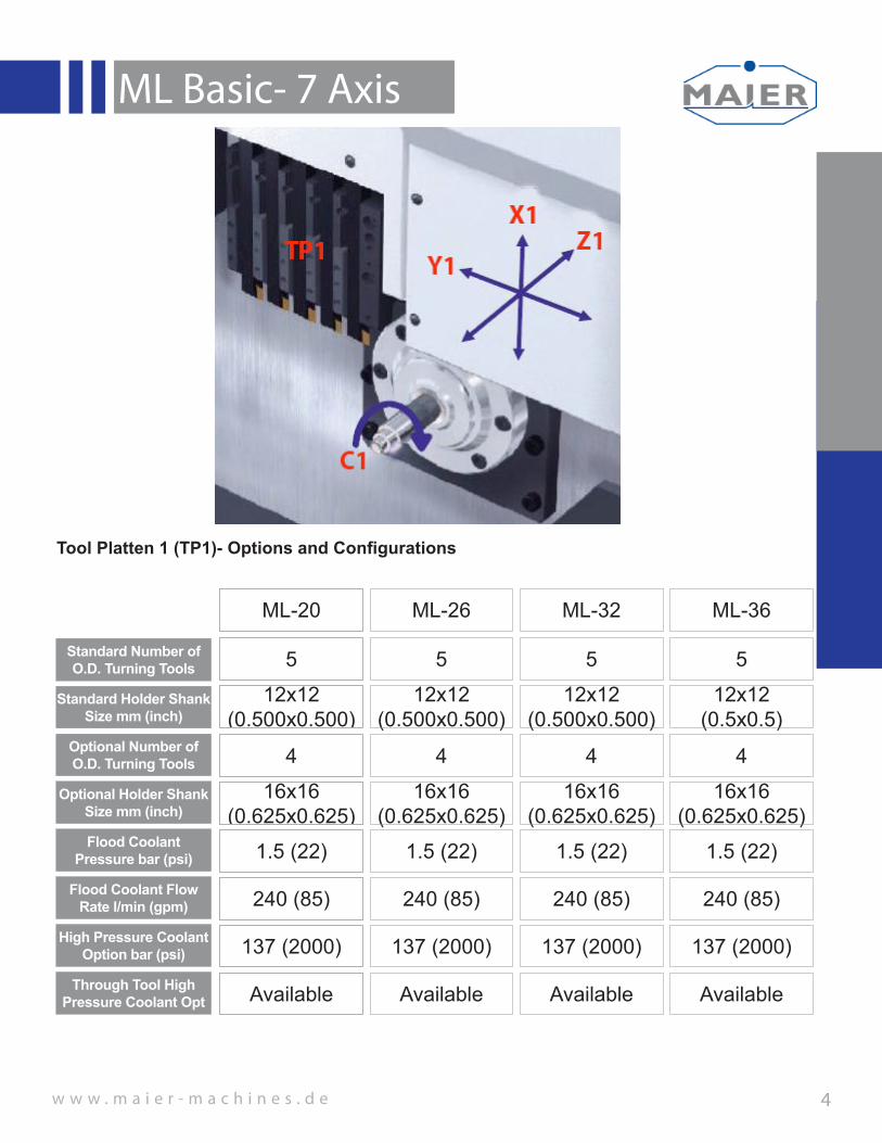
Standard Number of O.D. Turning Tools
ML-20
Standard Holder Shank Size mm (inch)
Optional Number of O.D. Turning Tools
Optional Holder Shank Size mm (inch)
ML-26 ML-32 ML-36
5 5 5 5
12x12 (0.500x0.500)
12x12 (0.500x0.500)
12x12 (0.500x0.500)
12x12 (0.5x0.5)
4 4 4 4
16x16 (0.625x0.625)
16x16(0.625x0.625)
16x16 (0.625x0.625)
16x16 (0.625x0.625)
Flood Coolant Pressure bar (psi)
Flood Coolant Flow Rate l/min (gpm)
1.5 (22) 1.5 (22) 1.5 (22) 1.5 (22)
240 (85) 240 (85) 240 (85) 240 (85)
High Pressure Coolant Option bar (psi)
Through Tool High Pressure Coolant Opt
137 (2000) 137 (2000) 137 (2000) 137 (2000)
Available Available Available Available
Tool Platten 1 (TP1)- Options and Configurations
w w w . m a i e r - m a c h i n e s . d e
ML Basic- 7 Axis
5
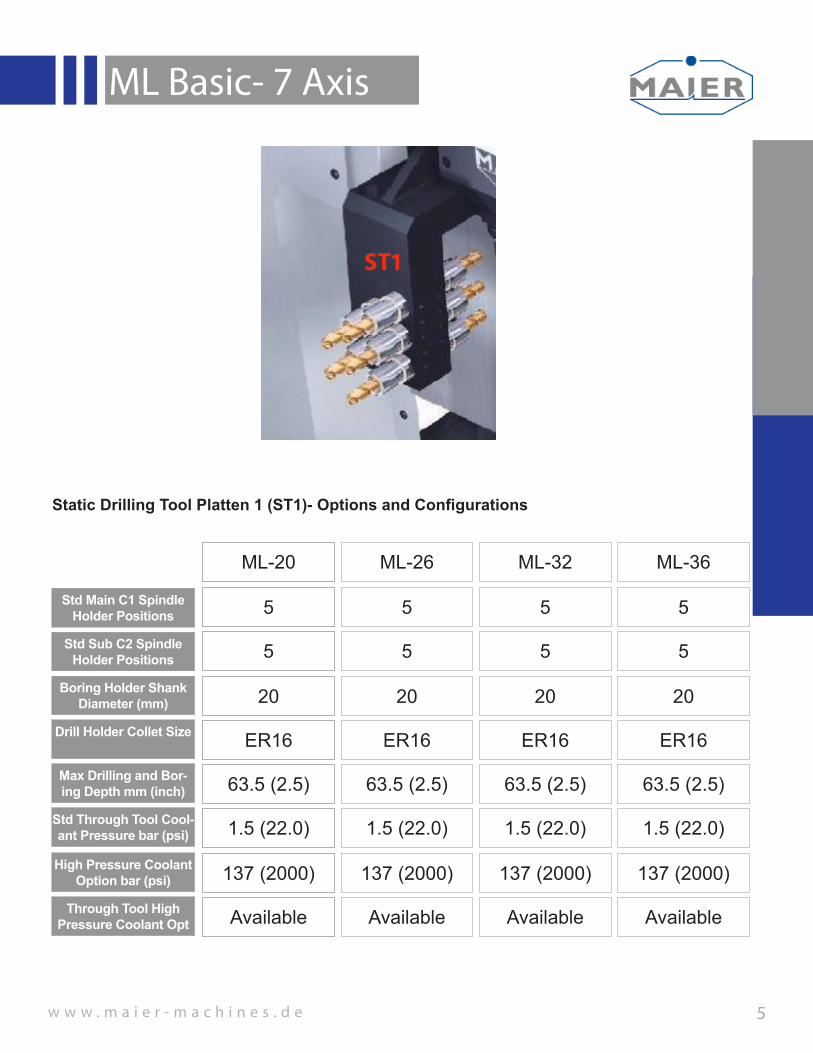
Std Main C1 Spindle Holder Positions
ML-20
Std Sub C2 Spindle Holder Positions
Boring Holder Shank Diameter (mm)
Drill Holder Collet Size
ML-26 ML-32 ML-36
5 5 5 5
5 5 5 5
20 20 20 20
ER16 ER16 ER16 ER16
Max Drilling and Bor-ing Depth mm (inch) 63.5 (2.5) 63.5 (2.5) 63.5 (2.5) 63.5 (2.5)
High Pressure Coolant Option bar (psi)
Through Tool High Pressure Coolant Opt
137 (2000) 137 (2000) 137 (2000) 137 (2000)
Available Available Available Available
Static Drilling Tool Platten 1 (ST1)- Options and Configurations
Std Through Tool Cool-ant Pressure bar (psi) 1.5 (22.0) 1.5 (22.0) 1.5 (22.0) 1.5 (22.0)

w w w . m a i e r - m a c h i n e s . d e
ML Basic- 7 Axis
6
Standard Number of Live Drilling Spindles
ML-20
Optional Number of Live Drilling Spindles
Boring Holder Shank Diameter (mm)
Standard Drill Holder Collet Size
ML-26 ML-32 ML-36
4 4 4 4
7ST1 Removed
7ST1 Removed
7ST1 Removed
7ST1 Removed
34 34 34 34
ER16 ER16 ER16 ER16
Max Drilling and Bor-ing Depth mm (inch) 25.0 (0.984) 25.0 (0.984) 25.0 (0.984) 25.0 (0.984)
Through Tool High Pressure Coolant Opt N/A N/A N/A N/A
Standard 6000rpm Live Tool Cross Drilling Platten 1 (LT1)- Options and Configurations
Optional Drill Holder Collet Size
ER204 Station
ER204 Station
ER204 Station
ER204 Station

w w w . m a i e r - m a c h i n e s . d e
ML Basic- 7 Axis
7
Standard Number of Live Drilling Spindles
ML-20
Optional Number of Live Drilling Spindles
Boring Holder Shank Diameter (mm)
Standard Drill Holder Collet Size
ML-26 ML-32 ML-36
4 4 4 4
N/A N/A N/A N/A
34 34 34 34
ER16 ER16 ER16 ER16
Max Drilling and Bor-ing Depth mm (inch) 76.2 (3.0) 76.2 (3.0) 76.2 (3.0) 76.2 (3.0)
Live Through Tool-Coolant Opt N/A N/A N/A N/A
Standard 6000rpm Live Tool Sub-Spindle Drilling Platten 2 (LT2)-Options and Configurations
Optional Drill Holder Collet Size ER20 ER20 ER20 ER20
Max Static Drilling/Bor-ing Depth mm (inch) 76.2 (3.0) 76.2 (3.0) 76.2 (3.0) 76.2 (3.0)
Static Through Tool-Coolant Opt bar (psi) 137 (2000) 137 (2000) 137 (2000) 137 (2000)
Static Drill Holder Col-let Size
ER16, ER20, ER25
ER16, ER20, ER25
ER16, ER20, ER25
ER16, ER20, ER25

w w w . m a i e r - m a c h i n e s . d e
ML Basic- 7 Axis
8
Horsepower kW (hp)
ML-20
Torque N*m (ft*lb)
Maximum Spindle Speed (rpm)
Minumum Remnant Length mm (inch)
ML-26 ML-32 ML-36
5.5 (7.3) 5.5 (7.3) 5.5 (7.3) 5.5 (7.3)
29.2 (21.5) 29.2 (21.5) 29.2 (21.5) 29.2 (21.5)
8000 8000 8000 8000
200.0 (7.87) 200.0 (7.87) 200.0 (7.87) 200.0 (7.87)
C1 Spindle Max Bar Diameter 20 (0.787) 26 (1.023) 32 (1.260) 36 (1.417)
C1 Spindle Collet Style TF25 F32-221 TF37 TF42
Standard C1 Spindle Configuration
C1 Spindle Liner Length mm (inch) 540.0 (21.26) 540.0 (21.26) 540.0 (21.26) 540.0 (21.26)
C1 Min Collet Clamp-ing Diameter mm (inch) 2.0 (0.079) 2.0 (0.079) 2.0 (0.079) 2.0 (0.079)
C1 Avg Collet Clamp-ing Travel mm (inch) 0.254 (0.010) 0.254 (0.010) 0.254 (0.010) 0.254 (0.010)
C1 Max Collet Clamp-ing Diameter mm (inch) 20 (0.787) 26 (1.023) 32 (1.260) 36 (1.417)
C1 Guide Bushing Model # TD25S CD25 TD32S TD36S
w w w . m a i e r - m a c h i n e s . d e
ML Basic- 7 Axis
9
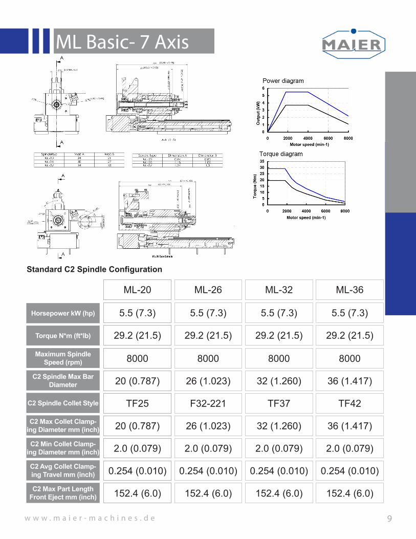
Horsepower kW (hp)
ML-20
Torque N*m (ft*lb)
Maximum Spindle Speed (rpm)
ML-26 ML-32 ML-36
5.5 (7.3) 5.5 (7.3) 5.5 (7.3) 5.5 (7.3)
29.2 (21.5) 29.2 (21.5) 29.2 (21.5) 29.2 (21.5)
8000 8000 8000 8000
C2 Spindle Max Bar Diameter 20 (0.787) 26 (1.023) 32 (1.260) 36 (1.417)
C2 Spindle Collet Style TF25 F32-221 TF37 TF42
Standard C2 Spindle Configuration
C2 Min Collet Clamp-ing Diameter mm (inch) 2.0 (0.079) 2.0 (0.079) 2.0 (0.079) 2.0 (0.079)
C2 Avg Collet Clamp-ing Travel mm (inch) 0.254 (0.010) 0.254 (0.010) 0.254 (0.010) 0.254 (0.010)
C2 Max Collet Clamp-ing Diameter mm (inch) 20 (0.787) 26 (1.023) 32 (1.260) 36 (1.417)
C2 Max Part Length Front Eject mm (inch) 152.4 (6.0) 152.4 (6.0) 152.4 (6.0) 152.4 (6.0)

w w w . m a i e r - m a c h i n e s . d e
ML Basic- 7 Axis
10
Machine Width mm (inch)
ML-20
Machine Depthmm (inch)
Machine Heightmm (inch)
ML-26 ML-32 ML-36
3324mm (130.87”)
3324mm (130.87”)
3324mm (130.87”)
3324mm (130.87”)
1954mm (76.93”)
1954mm (76.93”)
1954mm (76.93”)
1954mm (76.93”)
2159mm (85.0”)
2159mm (85.0”)
2159mm (85.0”)
2159mm (85.0”)
Machine Weightkg (lb) 3800 (8398) 3800 (8398) 3800 (8398) 3800 (8398)
Power Consumption 30KVA 30KVA 30KVA 30KVA
Standard Machine Layout
Standard Base Model Controller Fanuc 31iTB Fanuc 31iTB Fanuc 31iTB Fanuc 31iTB
Power Frequency 60Hz 60Hz 60Hz 60Hz
ML Series Standard Machine Layout- 12’ Bar Feeder Shown(Illustrated in First Angle Projection)
3324 2402
5513
9092,21
960
865
141
9
ca.250
646
215
9
(25.
43 in
ches
)
(94.57 inches)
(ca.9.84 inches)
(55.
87 in
ches
)
1504 (59.21 inches)
ca.150-200
ca.
800
ca.1000
ca.
600
335
450
OPEN DOOR(13.98 inches)
(ca.
31.5
inch
es)
(ca.
23.
62 in
ches
)
(17.
72 in
ches
)
(ca.39.37 inches)
(34.
06 in
ches
)
(37.8inches)
(130.87 inches)
(85
inch
es)
(ca.217.05 inches)
(ca.357.96 inches)
J
H
F
E
D
C
B
A
G
K
12111087654321 9
1615141312111091 2 3 4 5 6 7
M
L
K
J
H
G
A
B
C
D
E
8
F
0,2Für alle Bohrungen gilt:
-0,3+0,3
Werkstückkanten DIN 6784
This drawing and all information thereone is our property and may be confidental. It must not be made public or copied unless authorized by us and is subject to return upon request.
Diese Zeichnung ist unser Eigentum und darf ohne unsere Genehmigung weder vervielfältigt noch dritten Personen, insbesondere Konkurrenzfirmen ausgehändigt oder mitgeteilt werden.
111:20
A1Maßstab: Blatt:
Bezeichnung:
LAYOUT C5 WITH 4200 BAR FEEDER
MH
Gewicht in g: 6475650.89Material:
Zeichnungsnummer:
von
Artikel-Nr.:Ersteller:
Allgemeintoleranz: ISO 2768 - mH
Datum: 21.01.2015Geprüft von:
Nr. Änderung NameDatumOberflächenbeh.:Oberflächen: ISO 1302
Werkzeugmaschinen GmbH & Co.KGD-78564 Wehingen, Siemensstrasse 10 Tel.: +497426/5286-0 Fax: +497426/5286-50Mail: [email protected]: www.maier-machines.de
=
V=
Ra 6,3 y=
geschliffenRa 1,6
w=
Ra 3,2 z=
geschliffenRa 0,8
Ra 1,6x
w w w . m a i e r - m a c h i n e s . d e
ML Basic- 7 Axis
11
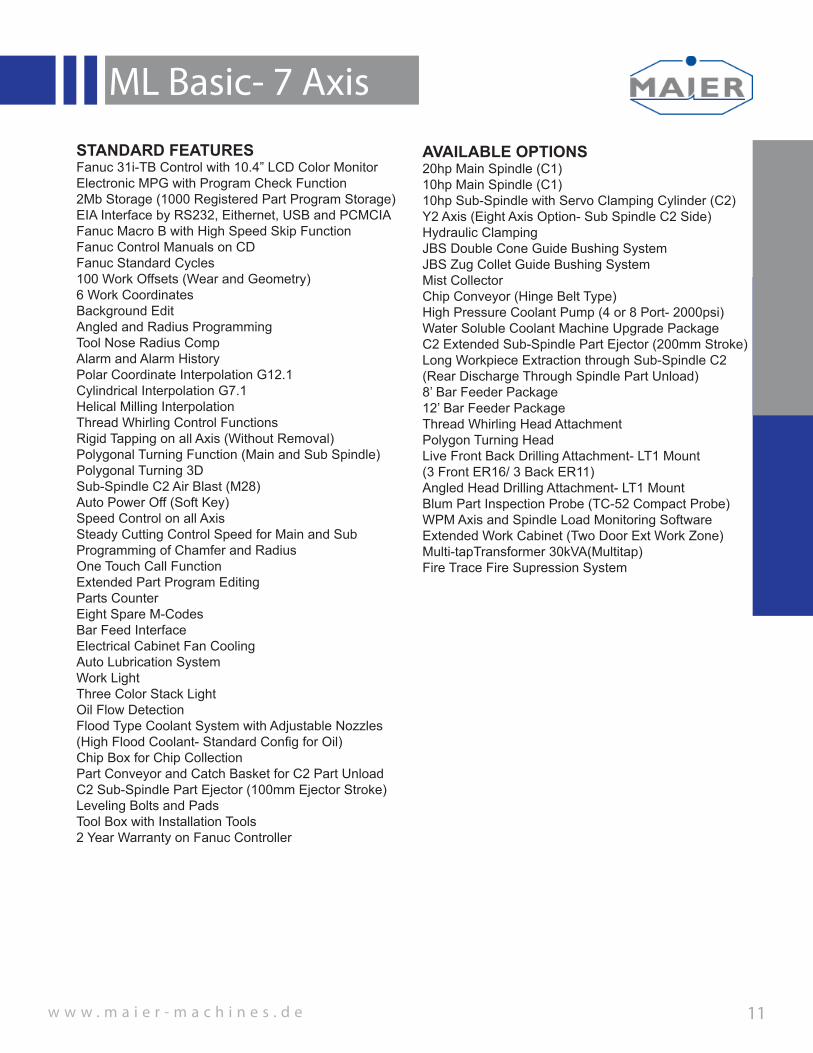
STANDARD FEATURESFanuc 31i-TB Control with 10.4” LCD Color MonitorElectronic MPG with Program Check Function2Mb Storage (1000 Registered Part Program Storage)EIA Interface by RS232, Eithernet, USB and PCMCIA Fanuc Macro B with High Speed Skip FunctionFanuc Control Manuals on CDFanuc Standard Cycles100 Work Offsets (Wear and Geometry)6 Work CoordinatesBackground EditAngled and Radius ProgrammingTool Nose Radius CompAlarm and Alarm HistoryPolar Coordinate Interpolation G12.1Cylindrical Interpolation G7.1Helical Milling InterpolationThread Whirling Control FunctionsRigid Tapping on all Axis (Without Removal)Polygonal Turning Function (Main and Sub Spindle)Polygonal Turning 3DSub-Spindle C2 Air Blast (M28)Auto Power Off (Soft Key)Speed Control on all AxisSteady Cutting Control Speed for Main and SubProgramming of Chamfer and RadiusOne Touch Call FunctionExtended Part Program EditingParts CounterEight Spare M-CodesBar Feed InterfaceElectrical Cabinet Fan CoolingAuto Lubrication SystemWork LightThree Color Stack LightOil Flow DetectionFlood Type Coolant System with Adjustable Nozzles(High Flood Coolant- Standard Config for Oil)Chip Box for Chip CollectionPart Conveyor and Catch Basket for C2 Part UnloadC2 Sub-Spindle Part Ejector (100mm Ejector Stroke)Leveling Bolts and PadsTool Box with Installation Tools2 Year Warranty on Fanuc Controller
AVAILABLE OPTIONS20hp Main Spindle (C1)10hp Main Spindle (C1)10hp Sub-Spindle with Servo Clamping Cylinder (C2)Y2 Axis (Eight Axis Option- Sub Spindle C2 Side)Hydraulic ClampingJBS Double Cone Guide Bushing SystemJBS Zug Collet Guide Bushing SystemMist CollectorChip Conveyor (Hinge Belt Type)High Pressure Coolant Pump (4 or 8 Port- 2000psi)Water Soluble Coolant Machine Upgrade PackageC2 Extended Sub-Spindle Part Ejector (200mm Stroke)Long Workpiece Extraction through Sub-Spindle C2(Rear Discharge Through Spindle Part Unload)8’ Bar Feeder Package12’ Bar Feeder PackageThread Whirling Head AttachmentPolygon Turning HeadLive Front Back Drilling Attachment- LT1 Mount(3 Front ER16/ 3 Back ER11)Angled Head Drilling Attachment- LT1 MountBlum Part Inspection Probe (TC-52 Compact Probe)WPM Axis and Spindle Load Monitoring SoftwareExtended Work Cabinet (Two Door Ext Work Zone) Multi-tapTransformer 30kVA(Multitap)Fire Trace Fire Supression System
w w w . m a i e r - m a c h i n e s . d e
ML Basic- 7 Axis
13
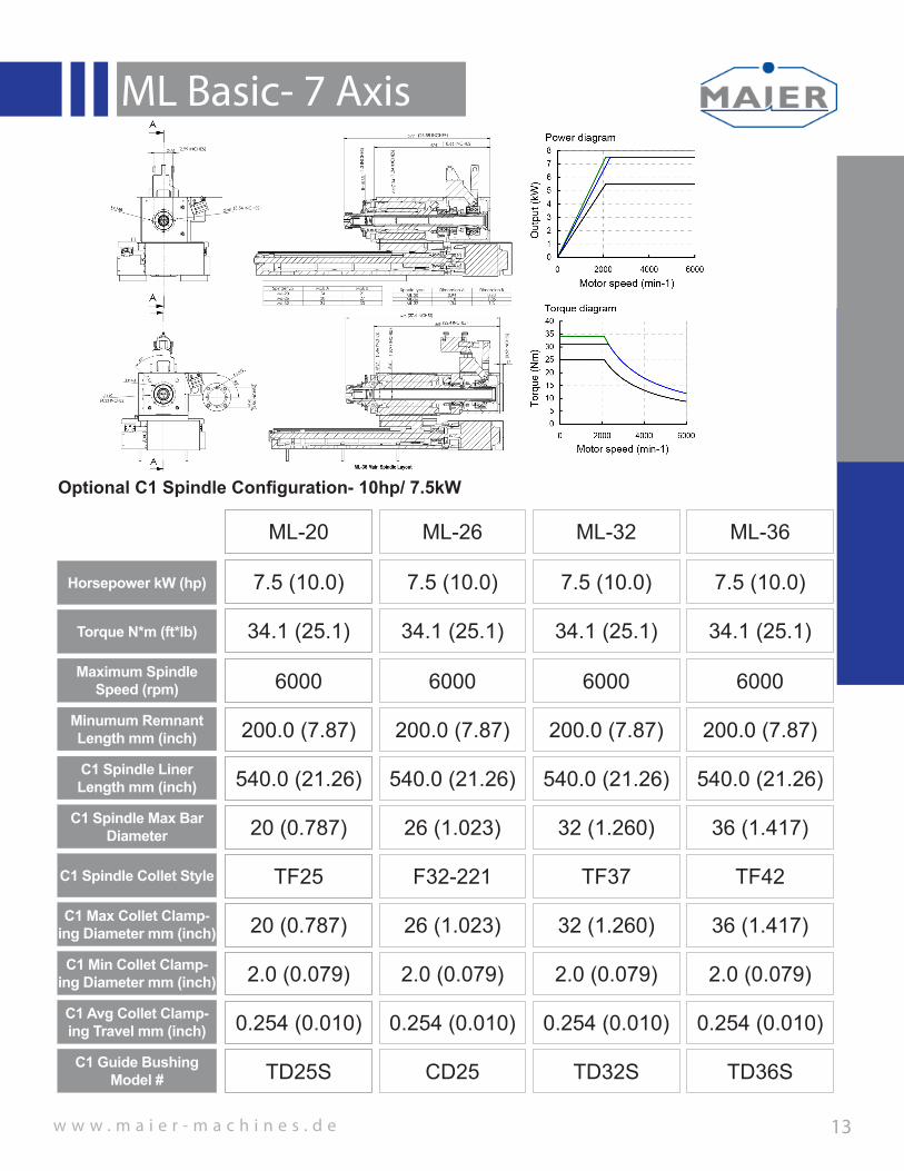
Horsepower kW (hp)
ML-20
Torque N*m (ft*lb)
Maximum Spindle Speed (rpm)
Minumum Remnant Length mm (inch)
ML-26 ML-32 ML-36
7.5 (10.0) 7.5 (10.0) 7.5 (10.0) 7.5 (10.0)
34.1 (25.1) 34.1 (25.1) 34.1 (25.1) 34.1 (25.1)
6000 6000 6000 6000
200.0 (7.87) 200.0 (7.87) 200.0 (7.87) 200.0 (7.87)
C1 Spindle Max Bar Diameter 20 (0.787) 26 (1.023) 32 (1.260) 36 (1.417)
C1 Spindle Collet Style TF25 F32-221 TF37 TF42
Optional C1 Spindle Configuration- 10hp/ 7.5kW
C1 Spindle Liner Length mm (inch) 540.0 (21.26) 540.0 (21.26) 540.0 (21.26) 540.0 (21.26)
C1 Min Collet Clamp-ing Diameter mm (inch) 2.0 (0.079) 2.0 (0.079) 2.0 (0.079) 2.0 (0.079)
C1 Avg Collet Clamp-ing Travel mm (inch) 0.254 (0.010) 0.254 (0.010) 0.254 (0.010) 0.254 (0.010)
C1 Max Collet Clamp-ing Diameter mm (inch) 20 (0.787) 26 (1.023) 32 (1.260) 36 (1.417)
C1 Guide Bushing Model # TD25S CD25 TD32S TD36S

w w w . m a i e r - m a c h i n e s . d e
ML Basic- 7 Axis
14
Horsepower kW (hp)
Torque N*m (ft*lb)
Maximum Spindle Speed (rpm)
Minumum Remnant Length mm (inch)
ML-32 ML-36
15.0 (20.0) 15.0 (20.0)
73.5 (54.2) 73.5 (54.2)
8000 8000
200.0 (7.87) 200.0 (7.87)
C1 Spindle Max Bar Diameter 32 (1.260) 36 (1.417)
C1 Spindle Collet Style TF37 TF42
Optional C1 Spindle Configuration- 20.0hp/ 15.0kW
C1 Spindle Liner Length mm (inch) 540.0 (21.26) 540.0 (21.26)
C1 Min Collet Clamp-ing Diameter mm (inch) 2.0 (0.079) 2.0 (0.079)
C1 Avg Collet Clamp-ing Travel mm (inch) 0.254 (0.010) 0.254 (0.010)
C1 Max Collet Clamp-ing Diameter mm (inch) 32 (1.260) 36 (1.417)
C1 Guide Bushing Model # TD32S TD36S

w w w . m a i e r - m a c h i n e s . d e
ML Basic- 7 Axis
15
Horsepower kW (hp)
Torque N*m (ft*lb)
Maximum Spindle Speed (rpm)
Minumum Remnant Length mm (inch)
ML-32 ML-36
15.0 (20.0) 15.0 (20.0)
73.5 (54.2) 73.5 (54.2)
8000 8000
200.0 (7.87) 200.0 (7.87)
C1 Spindle Max Bar Diameter 32 (1.260) 36 (1.417)
C1 Spindle Collet Style TF37 TF42
Optional C1 Hydraulic Clamping Spindle Configuration- 20.0hp/ 15.0kW
C1 Spindle Liner Length mm (inch) 540.0 (21.26) 540.0 (21.26)
C1 Min Collet Clamp-ing Diameter mm (inch) 2.0 (0.079) 2.0 (0.079)
C1 Avg Collet Clamp-ing Travel mm (inch) 0.254 (0.010) 0.254 (0.010)
C1 Max Collet Clamp-ing Diameter mm (inch) 32 (1.260) 36 (1.417)
C1 Guide Bushing Model # TD32S TD36S
4XM8
90
B
B
(3,54 INCHES)
845
41
40
40
708
B-B
(1,6
09 IN
CHE
S)
(1,57 INCHES)
(33,27 INCHES)
(27,87 INCHES)
(1,5
69 IN
CHE
S)
D
E
F
C
1 2 3 4
B
A
321 5
C
D
4 6 7 8
A
B
0,2Für alle Bohrungen gilt:
-0,3+0,3
Werkstückkanten DIN 6784
This drawing and all information thereone is our property and may be confidental. It must not be made public or copied unless authorized by us and is subject to return upon request.
Diese Zeichnung ist unser Eigentum und darf ohne unsere Genehmigung weder vervielfältigt noch dritten Personen, insbesondere Konkurrenzfirmen ausgehändigt oder mitgeteilt werden.
=
V=
Ra 6,3 y=
geschliffenRa 1,6
w=
Ra 3,2 z=
geschliffenRa 0,8
Ra 1,6x
Werkzeugmaschinen GmbH & Co.KGD-78564 Wehingen, Siemensstrasse 10 Tel.: +497426/5286-0 Fax: +497426/5286-50Mail: [email protected]: www.maier-machines.de
Oberflächen: ISO 1302 Oberflächenbeh.:Datum NameÄnderungNr.
Geprüft von:17.10.2014Datum:
Allgemeintoleranz: ISO 2768 - mH
Ersteller:Artikel-Nr.:
von
Zeichnungsnummer:
29242Material:
227897.04Gewicht in g:
MH
HBG Z1 -760 BASISSPINDEL MIT HYDR. SPANNER, VNK 102-46 171E2-036-C00-3100-2
Bezeichnung:
Blatt:Maßstab:
A31:5 1 1
Hydraulic Chuck Cross-Section View

w w w . m a i e r - m a c h i n e s . d e
ML Basic- 7 Axis
16
Horsepower kW (hp)
ML-20
Torque N*m (ft*lb)
Maximum Spindle Speed (rpm)
ML-26 ML-32 ML-36
7.5 (10.0) 7.5 (10.0) 7.5 (10.0) 7.5 (10.0)
34.1 (25.1) 34.1 (25.1) 34.1 (25.1) 34.1 (25.1)
6000 6000 6000 6000
C2 Spindle Max Bar Diameter 20 (0.787) 26 (1.023) 32 (1.260) 36 (1.417)
C2 Spindle Collet Style TF25 F32-221 TF37 TF42
Optional C2 Spindle Configuration- 10.0hp/7.5kW
C2 Min Collet Clamp-ing Diameter mm (inch) 2.0 (0.079) 2.0 (0.079) 2.0 (0.079) 2.0 (0.079)
C2 Avg Collet Clamp-ing Travel mm (inch) 0.254 (0.010) 0.254 (0.010) 0.254 (0.010) 0.254 (0.010)
C2 Max Collet Clamp-ing Diameter mm (inch) 20 (0.787) 26 (1.023) 32 (1.260) 36 (1.417)
C2 Max Part Length Front Eject mm (inch) 152.4 (6.0) 152.4 (6.0) 152.4 (6.0) 152.4 (6.0)

w w w . m a i e r - m a c h i n e s . d e
ML Basic- 7 Axis
17
Horsepower kW (hp)
ML-20
Torque N*m (ft*lb)
Maximum Spindle Speed (rpm)
ML-26 ML-32 ML-36
5.5 (7.3) 5.5 (7.3) 5.5 (7.3) 5.5 (7.3)
29.2 (21.5) 29.2 (21.5) 29.2 (21.5) 29.2 (21.5)
8000 8000 8000 8000
C2 Spindle Max Bar Diameter 20 (0.787) 26 (1.023) 32 (1.260) 36 (1.417)
C2 Spindle Collet Style TF25 F32-221 TF37 TF42
C2 Min Collet Clamp-ing Diameter mm (inch) 2.0 (0.010) 2.0 (0.010) 2.0 (0.010) 2.0 (0.010)
C2 Avg Collet Clamp-ing Travel mm (inch) 0.254 (0.010) 0.254 (0.010) 0.254 (0.010) 0.254 (0.010)
C2 Max Collet Clamp-ing Diameter mm (inch) 20 (0.787) 26 (1.023) 32 (1.260) 36 (1.417)
C2 Max Part Length Front Eject mm (inch) 152.4 (6.0) 152.4 (6.0) 152.4 (6.0) 152.4 (6.0)
Optional C2 Hydraulic Clamping Spindle Configuration- 7.3hp/5.5kW
4XM8
90°
90
A
A
C=804 BEI MLK +31
650
23,50 A
=37
B=
33
A-A
(3,54 INCHES)
(25.59 INCHES)
(31,65 INCHES)
(1,4
6 IN
CHE
S)
(1,2
9 IN
CHE
S)
(0,93 INCHES)
Spindeltyp Maß A Maß BML-20 37 21ML-26 37 27ML-32 37 33
Spindle type Dimension A Dimension BML-20 1,46 0,83ML-26 1,46 1,06ML-32 1,46 1,3
D
E
F
C
1 2 3 4
B
A
321 5
C
D
4 6 7 8
A
B
0,2Für alle Bohrungen gilt:
-0,3+0,3
Werkstückkanten DIN 6784
This drawing and all information thereone is our property and may be confidental. It must not be made public or copied unless authorized by us and is subject to return upon request.
Diese Zeichnung ist unser Eigentum und darf ohne unsere Genehmigung weder vervielfältigt noch dritten Personen, insbesondere Konkurrenzfirmen ausgehändigt oder mitgeteilt werden.
=
V=
Ra 6,3 y=
geschliffenRa 1,6
w=
Ra 3,2 z=
geschliffenRa 0,8
Ra 1,6x
Werkzeugmaschinen GmbH & Co.KGD-78564 Wehingen, Siemensstrasse 10 Tel.: +497426/5286-0 Fax: +497426/5286-50Mail: [email protected]: www.maier-machines.de
Oberflächen: ISO 1302 Oberflächenbeh.:Datum NameÄnderungNr.
Geprüft von:23.10.2014Datum:
Allgemeintoleranz: ISO 2768 - mH
Ersteller:Artikel-Nr.:
von
Zeichnungsnummer:
29423Material:
225347.50Gewicht in g:
MH
HBG Z1 -760 BASISSPINDEL MIT HYDR. SPANNER, VNK 070-37 1536E2-032-C00-3100-1
Bezeichnung:
Blatt:Maßstab:
A31:5 1 1 4XM8
90
B
B
(3,54 INCHES)
841
710
41
37
40
B-B
(1,6
09 IN
CHE
S)
(1,57 INCHES)
(33,11 INCHES)
(27,95 INCHES)
(1,4
6 IN
CHE
S)
D
E
F
C
1 2 3 4
B
A
321 5
C
D
4 6 7 8
A
B
0,2Für alle Bohrungen gilt:
-0,3+0,3
Werkstückkanten DIN 6784
This drawing and all information thereone is our property and may be confidental. It must not be made public or copied unless authorized by us and is subject to return upon request.
Diese Zeichnung ist unser Eigentum und darf ohne unsere Genehmigung weder vervielfältigt noch dritten Personen, insbesondere Konkurrenzfirmen ausgehändigt oder mitgeteilt werden.
=
V=
Ra 6,3 y=
geschliffenRa 1,6
w=
Ra 3,2 z=
geschliffenRa 0,8
Ra 1,6x
Werkzeugmaschinen GmbH & Co.KGD-78564 Wehingen, Siemensstrasse 10 Tel.: +497426/5286-0 Fax: +497426/5286-50Mail: [email protected]: www.maier-machines.de
Oberflächen: ISO 1302 Oberflächenbeh.:Datum NameÄnderungNr.
Geprüft von:17.10.2014Datum:
Allgemeintoleranz: ISO 2768 - mH
Ersteller:Artikel-Nr.:
von
Zeichnungsnummer:
29242Material:
230098.08Gewicht in g:
MH
HBG Z1 -760 BASISSPINDEL MIT HYDR. SPANNER, VNK 102-46 171E2-036-C00-3100-2
Bezeichnung:
Blatt:Maßstab:
A31:5 1 1
ML-36 Sub-Spindle Layout (Hydraulic) Hydraulic Chuck Cross-Section View

w w w . m a i e r - m a c h i n e s . d e
ML Basic- 7 Axis
18
Horsepower kW (hp)
ML-20
Torque N*m (ft*lb)
Maximum Spindle Speed (rpm)
ML-26 ML-32 ML-36
5.5 (7.3) 5.5 (7.3) 5.5 (7.3) 5.5 (7.3)
29.2 (21.5) 29.2 (21.5) 29.2 (21.5) 29.2 (21.5)
8000 8000 8000
C2 Spindle Max Bar Diameter 20 (0.787) 26 (1.023) 32 (1.260)
C2 Spindle Collet Style BN IIBN III
BN IIIBN IV BN IV
C2 Min Collet Clamp-ing Diameter mm (inch)
12.5 (0.492)19.0 (0.748)
19.0 (0.748)25.5 (1.004) 25.5 (1.004) 32.0 (1.260)
C2 Effective Collet Travel mm (inch)
6.5 (0.256)1.0 (0.039)
6.5 (0.256)0.5 (0.020) 6.5 (0.256) 4.0 (0.157)
C2 Max Collet Clamp-ing Diameter mm (inch)
19.0 (0.748)20.0 (0.787)
25.5 (1.004)26.0 (1.023) 32 (1.260) 36 (1.417)
C2 Max Part Length Front Eject mm (inch) 152.4 (6.0) 152.4 (6.0) 152.4 (6.0) 152.4 (6.0)
Optional C2 Hydraulic Clamping Spindle Configuration- 7.3hp/5.5kW (Extended Clamping Range- Forkardt Multi-Blade Collet Chuck LZK-S)
8000
32 (1.260)
BN V
Note: Reference Page 16 for Spindle Layout and Torque Diagrams

w w w . m a i e r - m a c h i n e s . d e
ML Basic- 7 Axis
19
Horsepower kW (hp)
ML-20
Torque N*m (ft*lb)
Maximum Spindle Speed (rpm)
ML-26 ML-32 ML-36
7.5 (10.0) 7.5 (10.0) 7.5 (10.0) 7.5 (10.0)
34.1 (25.1) 34.1 (25.1) 34.1 (25.1) 34.1 (25.1)
6000 6000 6000 6000
C2 Spindle Max Bar Diameter 20 (0.787) 26 (1.023) 32 (1.260) 36 (1.417)
Optional C2 Hydraulic Clamping Spindle Configuration- 10.0hp/7.5kW
4XM8
90°
90
A
A
C=804 BEI MLK +31
650
23,50
A=
37
B=
33
A-A
(3,54 INCHES)
(25.59 INCHES)
(31,65 INCHES)
(1,4
6 IN
CHE
S)
(1,2
9 IN
CHE
S)
(0,93 INCHES)
Spindeltyp Maß A Maß BML-20 37 21ML-26 37 27ML-32 37 33
Spindle type Dimension A Dimension BML-20 1,46 0,83ML-26 1,46 1,06ML-32 1,46 1,3
D
E
F
C
1 2 3 4
B
A
321 5
C
D
4 6 7 8
A
B
0,2Für alle Bohrungen gilt:
-0,3+0,3
Werkstückkanten DIN 6784
This drawing and all information thereone is our property and may be confidental. It must not be made public or copied unless authorized by us and is subject to return upon request.
Diese Zeichnung ist unser Eigentum und darf ohne unsere Genehmigung weder vervielfältigt noch dritten Personen, insbesondere Konkurrenzfirmen ausgehändigt oder mitgeteilt werden.
=
V=
Ra 6,3 y=
geschliffenRa 1,6
w=
Ra 3,2 z=
geschliffenRa 0,8
Ra 1,6x
Werkzeugmaschinen GmbH & Co.KGD-78564 Wehingen, Siemensstrasse 10 Tel.: +497426/5286-0 Fax: +497426/5286-50Mail: [email protected]: www.maier-machines.de
Oberflächen: ISO 1302 Oberflächenbeh.:Datum NameÄnderungNr.
Geprüft von:23.10.2014Datum:
Allgemeintoleranz: ISO 2768 - mH
Ersteller:Artikel-Nr.:
von
Zeichnungsnummer:
29423Material:
225347.50Gewicht in g:
MH
HBG Z1 -760 BASISSPINDEL MIT HYDR. SPANNER, VNK 070-37 1536E2-032-C00-3100-1
Bezeichnung:
Blatt:Maßstab:
A31:5 1 1 4XM8
90
B
B
(3,54 INCHES)
841
710
41
37
40
B-B
(1,6
09 IN
CHE
S)
(1,57 INCHES)
(33,11 INCHES)
(27,95 INCHES)
(1,4
6 IN
CHE
S)
D
E
F
C
1 2 3 4
B
A
321 5
C
D
4 6 7 8
A
B
0,2Für alle Bohrungen gilt:
-0,3+0,3
Werkstückkanten DIN 6784
This drawing and all information thereone is our property and may be confidental. It must not be made public or copied unless authorized by us and is subject to return upon request.
Diese Zeichnung ist unser Eigentum und darf ohne unsere Genehmigung weder vervielfältigt noch dritten Personen, insbesondere Konkurrenzfirmen ausgehändigt oder mitgeteilt werden.
=
V=
Ra 6,3 y=
geschliffenRa 1,6
w=
Ra 3,2 z=
geschliffenRa 0,8
Ra 1,6x
Werkzeugmaschinen GmbH & Co.KGD-78564 Wehingen, Siemensstrasse 10 Tel.: +497426/5286-0 Fax: +497426/5286-50Mail: [email protected]: www.maier-machines.de
Oberflächen: ISO 1302 Oberflächenbeh.:Datum NameÄnderungNr.
Geprüft von:17.10.2014Datum:
Allgemeintoleranz: ISO 2768 - mH
Ersteller:Artikel-Nr.:
von
Zeichnungsnummer:
29242Material:
230098.08Gewicht in g:
MH
HBG Z1 -760 BASISSPINDEL MIT HYDR. SPANNER, VNK 102-46 171E2-036-C00-3100-2
Bezeichnung:
Blatt:Maßstab:
A31:5 1 1
ML-36 Sub-Spindle Layout (Hydraulic) Hydraulic Chuck Cross-Section View
C2 Spindle Collet Style TF25 F32-221 TF37 TF42
C2 Min Collet Clamp-ing Diameter mm (inch) 2.0 (0.010) 2.0 (0.010) 2.0 (0.010) 2.0 (0.010)
C2 Avg Collet Clamp-ing Travel mm (inch) 0.254 (0.010) 0.254 (0.010) 0.254 (0.010) 0.254 (0.010)
C2 Max Collet Clamp-ing Diameter mm (inch) 20 (0.787) 26 (1.023) 32 (1.260) 36 (1.417)
C2 Max Part Length Front Eject mm (inch) 152.4 (6.0) 152.4 (6.0) 152.4 (6.0) 152.4 (6.0)

w w w . m a i e r - m a c h i n e s . d e
ML Basic- 7 Axis
20
Horsepower kW (hp)
ML-20
Torque N*m (ft*lb)
Maximum Spindle Speed (rpm)
ML-26 ML-32 ML-36
7.5 (10.0) 7.5 (10.0) 7.5 (10.0) 7.5 (10.0)
34.1 (25.1) 34.1 (25.1) 34.1 (25.1) 34.1 (25.1)
6000 6000 6000 6000
C2 Spindle Max Bar Diameter 20 (0.787) 26 (1.023) 32 (1.260) 36 (1.417)
C2 Spindle Collet Style BN IIBN III
BN IIIBN IV BN IV
C2 Min Collet Clamp-ing Diameter mm (inch)
12.5 (0.492)19.0 (0.748)
19.0 (0.748)25.5 (1.004) 25.5 (1.004) 32.0 (1.260)
C2 Effective Collet Travel mm (inch)
6.5 (0.256)1.0 (0.039)
6.5 (0.256)0.5 (0.020) 6.5 (0.256) 4.0 (0.157)
C2 Max Collet Clamp-ing Diameter mm (inch)
19.0 (0.748)20.0 (0.787)
25.5 (1.004)26.0 (1.023) 32 (1.260) 36 (1.417)
C2 Max Part Length Front Eject mm (inch) 152.4 (6.0) 152.4 (6.0) 152.4 (6.0) 152.4 (6.0)
BN V
Optional C2 Hydraulic Clamping Spindle Configuration- 10.0hp/7.5kW (Extended Clamping Range- Forkardt Multi-Blade Collet Chuck LZK-S)
Note: Reference Page 18 for Spindle Layout and Torque Diagrams

w w w . m a i e r - m a c h i n e s . d e
ML Basic- 7 Axis
21
Optional JBS Guide Bushing System Options(Recommended for Non-Ground or Variable Diameter Bar Stock)
Option #1- JBS Double Cone Self Adjusting System (General Application)
Option #2- JBS Zug Collet Self Adjusting System(High Accuracy/ Tight Runout Applications)
• Adjustment of Guide Tongs is +/-0.5mm (Bar Tolerance)
• Guide Clamp is Synchronized to spinde and adapts during the processing of the part.
• Quick Change System (3 minute changeover)• Self Adjusting• Designed to easily integrate with bar feed systems.• Designed to operate with all materials: 1) Plastics 2) High Alloyed Chromium Steels 3) Rolled Material DIN1013 4) All Aerospace and Automotive Ferious and Non-Ferious Materials• M Code Operated (Four Positions)
• Adjustment range of collet system is +/-0.15mm (Bar Tolerance)
• Guide Clamp is Synchronized to spinde and adapts during the processing of the part.
• Quick Change System (3 minute changeover)• Self Adjusting• High Concentricity• High Rigidity during milling operations.• Designed to easily integrate with bar feed systems.• Designed to operate with all materials: 1) Plastics 2) High Alloyed Chromium Steels 3) Rolled Material DIN1013 4) All Aerospace and Automotive Ferious and Non-Ferious Materials• M Code Operated (Four Positions)
w w w . m a i e r - m a c h i n e s . d e
ML Basic- 7 Axis
22
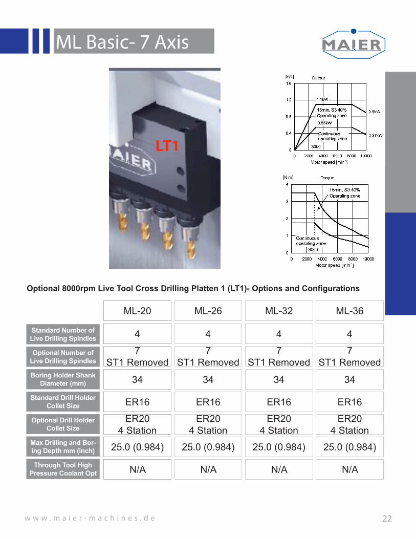
Standard Number of Live Drilling Spindles
ML-20
Optional Number of Live Drilling Spindles
Boring Holder Shank Diameter (mm)
Standard Drill Holder Collet Size
ML-26 ML-32 ML-36
4 4 4 4
7ST1 Removed
7ST1 Removed
7ST1 Removed
7ST1 Removed
34 34 34 34
ER16 ER16 ER16 ER16
Max Drilling and Bor-ing Depth mm (inch) 25.0 (0.984) 25.0 (0.984) 25.0 (0.984) 25.0 (0.984)
Through Tool High Pressure Coolant Opt N/A N/A N/A N/A
Optional 8000rpm Live Tool Cross Drilling Platten 1 (LT1)- Options and Configurations
Optional Drill Holder Collet Size
ER204 Station
ER204 Station
ER204 Station
ER204 Station

w w w . m a i e r - m a c h i n e s . d e
ML Basic- 7 Axis
23
Standard Number of Live Drilling Spindles
ML-20
Optional Number of Live Drilling Spindles
Boring Holder Shank Diameter (mm)
Standard Drill Holder Collet Size
ML-26 ML-32 ML-36
4 4 4 4
N/A N/A N/A N/A
34 34 34 34
ER16 ER16 ER16 ER16
Max Drilling and Bor-ing Depth mm (inch) 76.2 (3.0) 76.2 (3.0) 76.2 (3.0) 76.2 (3.0)
Live Through Tool-Coolant Opt N/A N/A N/A N/A
Optional 8000rpm Live Tool Sub-Spindle Drilling Platten 2 (LT2)- Options and Configurations
Optional Drill Holder Collet Size ER20 ER20 ER20 ER20
Max Static Drilling/Bor-ing Depth mm (inch) 76.2 (3.0) 76.2 (3.0) 76.2 (3.0) 76.2 (3.0)
Static Through Tool-Coolant Opt bar (psi) 137 (2000) 137 (2000) 137 (2000) 137 (2000)
Static Drill Holder Col-let Size
ER16, ER20, ER25
ER16, ER20, ER25
ER16, ER20, ER25
ER16, ER20, ER25

w w w . m a i e r - m a c h i n e s . d e
ML Basic- 7 Axis
24
Y2 Axis Travel mm (inch)
ML-20
Spindle X Axis Center to Center mm (inch)
ML-26 ML-32 ML-36
55.0 (2.165) 55.0 (2.165) 55.0 (2.165) 55.0 (2.165)
48.0 (1.89) 48.0 (1.89) 48.0 (1.89) 48.0 (1.89)
Live Tool Sub-Spindle Drilling Platten 2 (LT2)- Y2 Axis Eighth Axis Machine Option
Y2Axis
Y2Axis
Spindle Y Axis Center to Center mm (inch) 48.0 (1.89) 48.0 (1.89) 48.0 (1.89) 48.0 (1.89)

w w w . m a i e r - m a c h i n e s . d e
ML Basic- 7 Axis
25
Standard Number of Live Drilling Spindles
ML-20
Optional Number of Live Drilling Spindles
Boring Holder Shank Diameter (mm)
Standard Drill Holder Collet Size
ML-26 ML-32 ML-36
4(Bottom Row Live)
4(Bottom Row Live)
4(Bottom Row Live)
4(Bottom Row Live)
8 8 8 8
34 34 34 34
ER16 ER16 ER16 ER16
Max Drilling and Bor-ing Depth mm (inch) 76.2 (3.0) 76.2 (3.0) 76.2 (3.0) 76.2 (3.0)
Live Through Tool-Coolant Opt N/A N/A N/A N/A
Option 1- 6000rpm Live Tool Sub-Spindle Drilling Platten 2 (LT2)- Y2 Eighth Axis Configuration
Optional Drill Holder Collet Size ER20 ER20 ER20 ER20
Max Static Drilling/Bor-ing Depth mm (inch) 76.2 (3.0) 76.2 (3.0) 76.2 (3.0) 76.2 (3.0)
Static Through Tool-Coolant Opt bar (psi) 137 (2000) 137 (2000) 137 (2000) 137 (2000)
Static Drill Holder Col-let Size
ER16, ER20, ER25
ER16, ER20, ER25
ER16, ER20, ER25
ER16, ER20, ER25
Y2Axis LT2 (Eight Station Std)
Livetool Spindle Mount
Y2 Axis

w w w . m a i e r - m a c h i n e s . d e
ML Basic- 7 Axis
26
Standard Number of Live Drilling Spindles
ML-20
Optional Number of Live Drilling Spindles
Boring Holder Shank Diameter (mm)
Standard Drill Holder Collet Size
ML-26 ML-32 ML-36
4(Bottom Row Live)
4(Bottom Row Live)
4(Bottom Row Live)
4(Bottom Row Live)
8 8 8 8
34 34 34 34
ER16 ER16 ER16 ER16
Max Drilling and Bor-ing Depth mm (inch) 76.2 (3.0) 76.2 (3.0) 76.2 (3.0) 76.2 (3.0)
Live Through Tool-Coolant Opt N/A N/A N/A N/A
Option 2- 8000rpm Live Tool Sub-Spindle Drilling Platten 2 (LT2)- Y2 Eighth Axis Configuration
Optional Drill Holder Collet Size ER20 ER20 ER20 ER20
Max Static Drilling/Bor-ing Depth mm (inch) 76.2 (3.0) 76.2 (3.0) 76.2 (3.0) 76.2 (3.0)
Static Through Tool-Coolant Opt bar (psi) 137 (2000) 137 (2000) 137 (2000) 137 (2000)
Static Drill Holder Col-let Size
ER16, ER20, ER25
ER16, ER20, ER25
ER16, ER20, ER25
ER16, ER20, ER25
Y2Axis LT2 (Eight Station Std)
Livetool Spindle Mount
Y2 Axis
w w w . m a i e r - m a c h i n e s . d e
ML Basic- 7 Axis
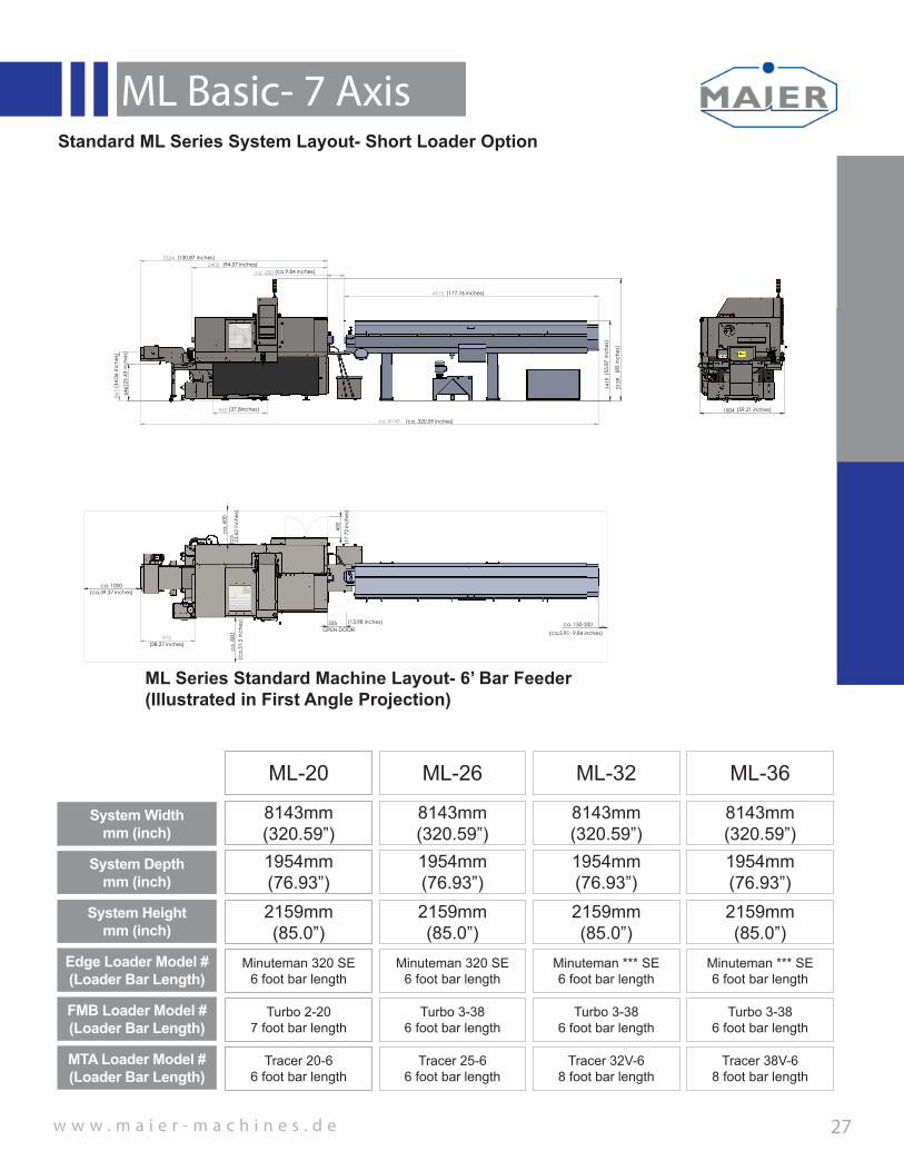
27
System Width mm (inch)
ML-20
System Depthmm (inch)
System Heightmm (inch)
ML-26 ML-32 ML-36
8143mm (320.59”)
8143mm (320.59”)
8143mm (320.59”)
8143mm (320.59”)
1954mm (76.93”)
1954mm (76.93”)
1954mm (76.93”)
1954mm (76.93”)
2159mm (85.0”)
2159mm (85.0”)
2159mm (85.0”)
2159mm (85.0”)
Edge Loader Model #(Loader Bar Length)
Minuteman 320 SE6 foot bar length
Minuteman 320 SE6 foot bar length
Minuteman *** SE6 foot bar length
Minuteman *** SE6 foot bar length
FMB Loader Model #(Loader Bar Length)
Turbo 2-207 foot bar length
Turbo 3-386 foot bar length
Turbo 3-386 foot bar length
Turbo 3-386 foot bar length
Standard ML Series System Layout- Short Loader Option
MTA Loader Model #(Loader Bar Length)
Tracer 20-66 foot bar length
Tracer 25-66 foot bar length
Tracer 32V-68 foot bar length
Tracer 38V-68 foot bar length
ca. 8143
4515
865
960
2402 3324
ca. 250
215
9
141
9
646
(37.8inches)
(177.76 inches)
(ca.9.84 inches)(94.57 inches)
1504 (59.21 inches)
972
335
ca.
800
ca. 1000
ca.
600
ca. 150-200
450
(ca.39.37 inches)
(ca.
31.5
inch
es)
(ca.
23.
62 in
ches
)
(13.98 inches)OPEN DOOR (ca.5.91- 9.84 inches)
(38.27 inches)
(34.
06 in
ches
)
(25.
43 in
ches
)
(85
inch
es)
(ca..320.59 inches)
(55.
87 in
ches
)
(130.87 inches)
(17.
72 in
ches
)
J
H
F
E
D
C
B
A
G
K
12111087654321 9
1615141312111091 2 3 4 5 6 7
M
L
K
J
H
G
A
B
C
D
E
8
F
0,2Für alle Bohrungen gilt:
-0,3+0,3
Werkstückkanten DIN 6784
This drawing and all information thereone is our property and may be confidental. It must not be made public or copied unless authorized by us and is subject to return upon request.
Diese Zeichnung ist unser Eigentum und darf ohne unsere Genehmigung weder vervielfältigt noch dritten Personen, insbesondere Konkurrenzfirmen ausgehändigt oder mitgeteilt werden.
111:20
A1Maßstab: Blatt:
Bezeichnung:
LAYOUT C5 WITH 3200 BAR FEEDER
MH
Gewicht in g: 4725988.31Material:
Zeichnungsnummer:
von
Artikel-Nr.:Ersteller:
Allgemeintoleranz: ISO 2768 - mH
Datum: 21.01.2015Geprüft von:
Nr. Änderung NameDatumOberflächenbeh.:Oberflächen: ISO 1302
Werkzeugmaschinen GmbH & Co.KGD-78564 Wehingen, Siemensstrasse 10 Tel.: +497426/5286-0 Fax: +497426/5286-50Mail: [email protected]: www.maier-machines.de
=
V=
Ra 6,3 y=
geschliffenRa 1,6
w=
Ra 3,2 z=
geschliffenRa 0,8
Ra 1,6x
ML Series Standard Machine Layout- 6’ Bar Feeder(Illustrated in First Angle Projection)
w w w . m a i e r - m a c h i n e s . d e
ML Basic- 7 Axis
28
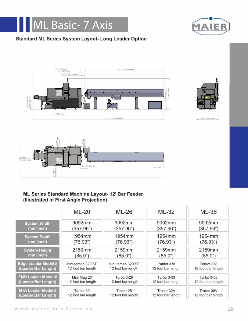
System Width mm (inch)
ML-20
System Depthmm (inch)
System Heightmm (inch)
ML-26 ML-32 ML-36
9092mm (357.96”)
9092mm (357.96”)
9092mm (357.96”)
9092mm (357.96”)
1954mm (76.93”)
1954mm (76.93”)
1954mm (76.93”)
1954mm (76.93”)
2159mm (85.0”)
2159mm (85.0”)
2159mm (85.0”)
2159mm (85.0”)
Edge Loader Model #(Loader Bar Length)
Minuteman 320 SE12 foot bar length
Minuteman 320 SE12 foot bar length
Patriot 33812 foot bar length
Patriot 33812 foot bar length
FMB Loader Model #(Loader Bar Length)
Mini Mag 20 12 foot bar length
Turbo 3-2612 foot bar length
Turbo 3-3812 foot bar length
Turbo 3-3812 foot bar length
MTA Loader Model #(Loader Bar Length)
Tracer 2012 foot bar length
Tracer 2512 foot bar length
Tracer 32V12 foot bar length
Tracer 38V12 foot bar length
Standard ML Series System Layout- Long Loader Option
ML Series Standard Machine Layout- 12’ Bar Feeder(Illustrated in First Angle Projection)
3324 2402
5513
9092,21
960
865
141
9
ca.250
646
215
9
(25.
43 in
ches
)
(94.57 inches)
(ca.9.84 inches)
(55.
87 in
ches
)
1504 (59.21 inches)
ca.150-200
ca.
800
ca.1000
ca.
600
335
450
OPEN DOOR(13.98 inches)
(ca.
31.5
inch
es)
(ca.
23.
62 in
ches
)
(17.
72 in
ches
)
(ca.39.37 inches)
(34.
06 in
ches
)
(37.8inches)
(130.87 inches)
(85
inch
es)
(ca.217.05 inches)
(ca.357.96 inches)
J
H
F
E
D
C
B
A
G
K
12111087654321 9
1615141312111091 2 3 4 5 6 7
M
L
K
J
H
G
A
B
C
D
E
8
F
0,2Für alle Bohrungen gilt:
-0,3+0,3
Werkstückkanten DIN 6784
This drawing and all information thereone is our property and may be confidental. It must not be made public or copied unless authorized by us and is subject to return upon request.
Diese Zeichnung ist unser Eigentum und darf ohne unsere Genehmigung weder vervielfältigt noch dritten Personen, insbesondere Konkurrenzfirmen ausgehändigt oder mitgeteilt werden.
111:20
A1Maßstab: Blatt:
Bezeichnung:
LAYOUT C5 WITH 4200 BAR FEEDER
MH
Gewicht in g: 6475650.89Material:
Zeichnungsnummer:
von
Artikel-Nr.:Ersteller:
Allgemeintoleranz: ISO 2768 - mH
Datum: 21.01.2015Geprüft von:
Nr. Änderung NameDatumOberflächenbeh.:Oberflächen: ISO 1302
Werkzeugmaschinen GmbH & Co.KGD-78564 Wehingen, Siemensstrasse 10 Tel.: +497426/5286-0 Fax: +497426/5286-50Mail: [email protected]: www.maier-machines.de
=
V=
Ra 6,3 y=
geschliffenRa 1,6
w=
Ra 3,2 z=
geschliffenRa 0,8
Ra 1,6x

w w w . m a i e r - m a c h i n e s . d e
ML Basic- 7 Axis
29
System Width mm (inch)
ML-20
System Depthmm (inch)
System Heightmm (inch)
ML-26 ML-32 ML-36
7892mm (310.70”)
7892mm (310.70”)
7892mm (310.70”)
7892mm (310.70”)
2094mm (82.44”)
2094mm (82.44”)
2094mm (82.44”)
2094mm (82.44”)
2275mm (89.57”)
2275mm (89.57”)
2275mm (89.57”)
2275mm (89.57”)
Edge Loader Model #(Loader Bar Length)
Minuteman 320 SE6 foot bar length
Minuteman 320 SE6 foot bar length
Minuteman *** SE6 foot bar length
Minuteman *** SE6 foot bar length
FMB Loader Model #(Loader Bar Length)
Turbo 2-207 foot bar length
Turbo 3-386 foot bar length
Turbo 3-386 foot bar length
Turbo 3-386 foot bar length
Expanded Cabinet ML Series System Layout- Short Loader Option
MTA Loader Model #(Loader Bar Length)
Tracer 20-66 foot bar length
Tracer 25-66 foot bar length
Tracer 32V-68 foot bar length
Tracer 38V-68 foot bar length
ML Series Expanded Cabinet Machine Layout- 6’ Bar Feeder(Illustrated in First Angle Projection)
ca. 7892
141
9 2
275
646
960
872
2607
ca.250
4320 3322
(25.
43 in
ches
)
1644
972
255
ca.
800
ca.
600
ca.150-200
ca.1000
9042
278
0
450
(38.27 inches)
(10.04 inches)
OPEN DOOR
(ca.39.37 inches)
(ca.
23.
62 in
ches
)(c
a.31
.5 in
ches
) (ca.5.91-7.87 inches)
(109
.45
inch
es)(1
5.75
inch
es)
(34.
33 in
ches
)
(37.8 inches)
(310.71 inches)
(170.08 inches)
(89.
57 in
ches
)
(55.
87 in
ches
)
(64.72 inches)
ca.
ca. (355.98 inches)
(130.79 inches)
(102.64 inches)
(ca.9.84 inches)
J
H
F
E
D
C
B
A
G
K
12111087654321 9
1615141312111091 2 3 4 5 6 7
M
L
K
J
H
G
A
B
C
D
E
8
F
0,2Für alle Bohrungen gilt:
-0,3+0,3
Werkstückkanten DIN 6784
This drawing and all information thereone is our property and may be confidental. It must not be made public or copied unless authorized by us and is subject to return upon request.
Diese Zeichnung ist unser Eigentum und darf ohne unsere Genehmigung weder vervielfältigt noch dritten Personen, insbesondere Konkurrenzfirmen ausgehändigt oder mitgeteilt werden.
111:20
A1Maßstab: Blatt:
Bezeichnung:
ML A-D 3200 BAR FEEDER
MH
Gewicht in g: 4771267.15Material:
Zeichnungsnummer:
von
Artikel-Nr.:Ersteller:
Allgemeintoleranz: ISO 2768 - mH
Datum: 21.01.2015Geprüft von:
Nr. Änderung NameDatumOberflächenbeh.:Oberflächen: ISO 1302
Werkzeugmaschinen GmbH & Co.KGD-78564 Wehingen, Siemensstrasse 10 Tel.: +497426/5286-0 Fax: +497426/5286-50Mail: [email protected]: www.maier-machines.de
=
V=
Ra 6,3 y=
geschliffenRa 1,6
w=
Ra 3,2 z=
geschliffenRa 0,8
Ra 1,6x
Expanded Cabinet Requiredfor the following Options;1) Z2 Extention to 350mm2) Hydraulic Clamping3) Y2 Axis Option
w w w . m a i e r - m a c h i n e s . d e
ML Basic- 7 Axis
30
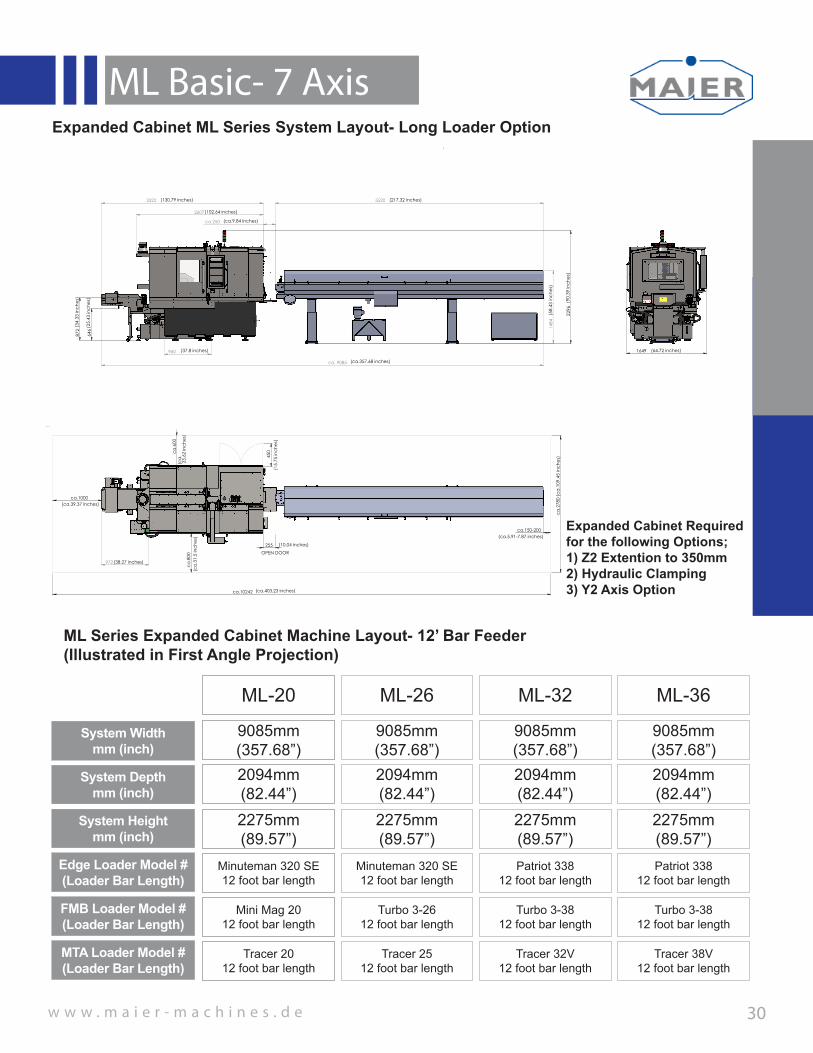
System Width mm (inch)
ML-20
System Depthmm (inch)
System Heightmm (inch)
ML-26 ML-32 ML-36
9085mm (357.68”)
9085mm (357.68”)
9085mm (357.68”)
9085mm (357.68”)
2094mm (82.44”)
2094mm (82.44”)
2094mm (82.44”)
2094mm (82.44”)
2275mm (89.57”)
2275mm (89.57”)
2275mm (89.57”)
2275mm (89.57”)
Edge Loader Model #(Loader Bar Length)
Minuteman 320 SE12 foot bar length
Minuteman 320 SE12 foot bar length
Patriot 33812 foot bar length
Patriot 33812 foot bar length
FMB Loader Model #(Loader Bar Length)
Mini Mag 20 12 foot bar length
Turbo 3-2612 foot bar length
Turbo 3-3812 foot bar length
Turbo 3-3812 foot bar length
MTA Loader Model #(Loader Bar Length)
Tracer 2012 foot bar length
Tracer 2512 foot bar length
Tracer 32V12 foot bar length
Tracer 38V12 foot bar length
Expanded Cabinet ML Series System Layout- Long Loader Option
ML Series Expanded Cabinet Machine Layout- 12’ Bar Feeder(Illustrated in First Angle Projection)
ca. 9085
148
4
960
2607
3322
ca.250
5520
229
6
646
872
(34
.33
inch
es)
(37.8 inches)
(ca.357.68 inches)
(ca.9.84 inches)
1649 (64.72 inches)
972
255
ca.150-200
ca
.800
ca.1000
ca
.600
ca
.278
0
450
ca.10242
OPEN DOOR
(10.04 inches)
(ca.5.91-7.87 inches)
(ca
.31.
5 in
ches
)
(15.
75 in
ches
)
(ca
. 2
3.62
inch
es)
(ca.39.37 inches)
(25.
43 in
ches
)
(58.
43 in
ches
)
(90.
39 in
ches
)(38.27 inches)
(130.79 inches)
(102.64 inches)
(217.32 inches)
(ca
.109
.45
inch
es)
(ca.403.23 inches)
J
H
F
E
D
C
B
A
G
K
12111087654321 9
1615141312111091 2 3 4 5 6 7
M
L
K
J
H
G
A
B
C
D
E
8
F
0,2Für alle Bohrungen gilt:
-0,3+0,3
Werkstückkanten DIN 6784
This drawing and all information thereone is our property and may be confidental. It must not be made public or copied unless authorized by us and is subject to return upon request.
Diese Zeichnung ist unser Eigentum und darf ohne unsere Genehmigung weder vervielfältigt noch dritten Personen, insbesondere Konkurrenzfirmen ausgehändigt oder mitgeteilt werden.
111:20
A1Maßstab: Blatt:
Bezeichnung:
ML A-D 4200 BAR FEEDER
MH
Gewicht in g: 6530384.11Material:
Zeichnungsnummer:
von
Artikel-Nr.:Ersteller:
Allgemeintoleranz: ISO 2768 - mH
Datum: 21.01.2015Geprüft von:
Nr. Änderung NameDatumOberflächenbeh.:Oberflächen: ISO 1302
Werkzeugmaschinen GmbH & Co.KGD-78564 Wehingen, Siemensstrasse 10 Tel.: +497426/5286-0 Fax: +497426/5286-50Mail: [email protected]: www.maier-machines.de
=
V=
Ra 6,3 y=
geschliffenRa 1,6
w=
Ra 3,2 z=
geschliffenRa 0,8
Ra 1,6x
Expanded Cabinet Requiredfor the following Options;1) Z2 Extention to 350mm2) Hydraulic Clamping3) Y2 Axis Option

31V2014.11
Maier Machine GMBH- GermanyCorporate HeadquartersSiemensstrasse 10Postfach 1124-78560 WehingenGermanyPhone: 01149-7426-52 86-0Fax: 01149-7428-52 86-50
Maier Machines & RobiticsHeadquarters- North America19 Ohio AvenueNorwich, CT 06360Phone: (508)671-0055Fax: (860)823-0623Email: [email protected]
V2014.11


