18
APPLICATION NOTE ML8720B W-CDMA Area Tester BCH Demodulation Function ANRITSU CORPORATION
APPLICATION NOTE
ML8720B W-CDMA Area Tester
BCH Demodulation Function
ANRITSU CORPORATION

CONFIDENTIAL 1
Copyright 2005 by ANRITSU CORPORATION The contents of this manual shall not be disclosed in any way or reproduced in any media without the express written permission of Anritsu Corporation.

1
Slide 1ML8720B-E-F-2
New option for the Anritsu ML8720BW-CDMA Area Tester
Anritsu CorporationWireless Measurement Division
June 2005
BCH Demodulation Function
Slide 2ML8720B-E-F-2
In the process of 3G network optimization, there are many serious concerns.Through customer visits, we determined that the major factors are:
a. Incorrect parameter setup at Node B
b. Interference and noise in the Uplink
Resultant Effects1. Call Drops: When a subscriber moves to a neighbor cell2. Unable to make a call: In spite of the mobile device indicating coverage 3. Slow data transmission: When downloading data such as pictures
PART 1Introduction to BCH Demodulation
BCH Demodulation provides a solution

2
Slide 3ML8720B-E-F-2
What is BCH Demodulation?
BCH: Broadcast Channel• This is one of the Downlink Transport Channels• It is always transmitted to all Cells via the P-CCPCH
(Primary Common Control Physical Channel)
• It broadcasts fixed System and Cell information
Some of the Information transmitted by BCHCell ID, RNC Parameters, Measured Uplink Interference Power, Peripheral Cell Information, etc...
Slide 4ML8720B-E-F-2
Value 1: Detection of incorrect Node-B parameters
At the time of optimization, field engineers are sometimes not 100% sure of the current values and their validity.
RNC Parameters
Cell-Id
Transmit Power
Neighbor Cell List
??
?
?
aa
Node-B ParametersThe initial values are changed as a result of either network field trials and debugging or coverage analysis of the radio environment.
A wrong parameter on a neighbor cell list may result in handover failure.

3
Slide 5ML8720B-E-F-2
The value of the Node-B parameters can be checked by means of the BCH demodulation feature without the need to access the site or NOC.
RNC Parameters
Cell-Id
Transmit Power
Neighbor Listaa
Broadcast and cell-specific information contained in BCH (SIB1, SIB2, …, SIB18)
Value 1: Detection of incorrect Node-B parameters
This ensures optimization of the area under the correct Node-B conditions.
Slide 6ML8720B-E-F-2
Broadcast Informationin BCH (SIB1, 2,……18)
Example of captured data:
SIB3: Cell ID
SIB5: Transmission Power
SIB11: Neighbor List
+
Few measurements other than P-CPICH made
Value 1: Detection of incorrect Node-B parameters
Before Now
P-CPICH measurements +
BCH demodulation

4
Slide 7ML8720B-E-F-2
Uplink interference can be caused by…..
Other 3G UEs within the cell- Poor power control (NW and UE)
RF sourcesOther electrical/electronic noise
Excessive Uplink interference will cause restrictions to cell traffic.
Value 2: Evaluation of interference in the Uplink
All these sources can generate energy that
results in interference even though EMC
and UE conformance testing is strict.
W-CDMA systems are noise limited,so communications can often
be disrupted by noise and interference.
aa
Slide 8ML8720B-E-F-2
Value 2: Evaluation of interference in the Uplink
Using the ML8720B, it is possible to check the UL-Interference level, recorded at the Node-B, by demodulating the BCH and extracting the
reported UL-Interference in the cell information from the SIB7 messages.
aa
Uplink
Uplink
UL Interferencein BCH (SIB Type 7)

5
Slide 9ML8720B-E-F-2
aa
The Anritsu ML8720B makes its measurements in real time and can capture ‘bursty’ interference.
Value 2: Evaluation of interference in the Uplink
Key pointGenerally, the NOC (OMC) averages the value
of the Node-B interference over a 15 minute period.
When the value of UL-Interference is large in an area where the traffic is low, a high level of interference may be restricting cell traffic.
As a result, it is impossible to catch ‘bursty’ interference
Slide 10ML8720B-E-F-2
Comparison 1: UE and ML8720BEvery UE supports BCH Demodulation, however there are functional restrictions.
1. A UE demodulates only at times controlled by the UE Protocol Stack.• When the UE is first switched on and registers on the network • When a handover is initiated• In the call setup routine…
2. A UE cannot demodulate BCH signals from a specified Node-B.
BCH Demodulation on ML8720B is continuous, real time, and calibrated

6
Slide 11ML8720B-E-F-2
3. There is a Data Synchronization Difficulty Even if there are some restrictions, it is possible to demodulate BCH with a UE. However it is difficult to merge and synchronize the demodulated signals and data received by a UE with P-CPICH received by a scanner.
When there is a call drop problem likely caused by high UL- Interference, it is necessary to compare the location and time of the downlink measurement data with the broadcast information.
By comparing this information, one can understand if the problem was caused by Uplink interference, Downlink interference, or erroneous Node-B parameters.
Comparison 2: UE and ML8720B
The ML8720B can save all the necessary information to compare.
Slide 12ML8720B-E-F-2
Demodulation Data: MIB, SB1, SB2, and SIB1 to SIB18 [Related Standard: TS25.331]
The measurement period for SIB7 is selectable from 2 to 300 sec.As for other SIBs, the measurement period is not specified and depends on the radio environment. Current thoughts are to set the measurement period to around 10 sec(3 times the retry time).
Performance: Processing time: 0.5s (2 frames of P-CCPCH)Probability: more than 50% (typical 70%) at SIR10dB, 0 to 100km/h
BCH Demodulation function: Basic Specifications

7
Slide 13ML8720B-E-F-2
The purpose of ML8720B BCH Demodulation is to use SIB (System Information Block) information. SIB information helps find problems like call drop or handover failure.
SIB information ranges from 1 to 18,and some of these will be used for future applications.Currently, the most important SIBsare SIB3, 5, 7, and 11 because most of the current optimization problems are related to these items. In this document,we introduce the application orvalue of the information fromthese SIBs. Anritsu’s BCH Demodulation software providesSIB3 and SIB7 in real-time.
PART 2Anritsu BCH Demodulation Software Applications
Slide 14ML8720B-E-F-2
SIB3 (Cell ID): Application 1The value of using SIB3 information is to identify the measured cell. A UE checks its location using this information.
Without Cell ID, those cells with the same scrambling code might cause confusion and one cannot ensure which Node-B a detected signal originated from.
When making a drive test in a densely populated area, one can see that some scrambling codes from different cells are the same. This happens because the number of primary scrambling codes is limited to 512.
By demodulating SIB3 one can check in real-time that the detected signal is the correct one (assuming connection to a data collection tool.)
?

8
Slide 15ML8720B-E-F-2
One can check if the current signal is from the nearest cell by SIB3. If not, the call can drop as the neighbor cell list will be in correct for the UE’s actual location.
SIB3 (Cell ID): Application 2
In most cases, this can be verified by the scramblingCode, but many operators manage cell maintenance by Cell ID rather than by scrambling code. Therefore, it is easier to compare the measurementdata with the Cell ID information held at NOC. Also, this can avoid the confusing situation of the same scrambling code being used for different cells.
By SIB3 demodulation one can check in real time that the detected signal is from the nearest cell (assuming connection with a data collection tool.)
?
A
Slide 16ML8720B-E-F-2
SIB5 (Transmission Power): Application
If the actual power is less than the estimated simulatedvalue, it is assumed that the UE detects only reflectedsignals due to obstacles such as buildings.
If the actual power is larger than the estimatedsimulated value, it indicates that there is something wrong with the power control system of the Node-B or that there are erroneous parameter settings.
? With SIB5, one can check that the parameters on the specificNode-B are correct (used together with SIB3 information)
The purpose of using the SIB5 information is to compare the transmitted power from the Node-B as measured by the ML8720, with the estimated value which is calculated by subtracting the theoretical power loss due to distance from the Node-B Tx power value stated in SIB5.
9
Slide 17ML8720B-E-F-2
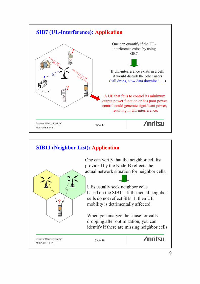
SIB7 (UL-Interference): Application
One can quantify if the UL-interference exists by using
SIB7.
If UL-interference exists in a cell,it would disturb the other users
(call drops, slow data download,…)
A UE that fails to control its minimum output power function or has poor power control could generate significant power,
resulting in UL-interference.
?
?
Slide 18ML8720B-E-F-2
SIB11 (Neighbor List): Application
?
One can verify that the neighbor cell listprovided by the Node-B reflects the actual network situation for neighbor cells.
UEs usually seek neighbor cells based on the SIB11. If the actual neighbor cells do not reflect SIB11, then UE mobility is detrimentally affected.
When you analyze the cause for calls dropping after optimization, you can identify if there are missing neighbor cells.

10
Slide 19ML8720B-E-F-2
In conjunction with Option 03 (2nd RF)
If the BCH demodulation function is used in conjunction with option 03(2nd RF), it can provide a BCH benchmark between operators.
One can compare the SIB parameters for each operator. This combined solution is provided only by the Anritsu scanner because option 03 is also equipped with an another rake receiver*.
Operator A Operator B
*Some other scanners support 8 or 12 frequencies with 1rake receiver and the frequencies are switched by software.Even if a BCH feature is supported in the future, it will not be possible to do a simultaneous BCH demodulation of2 frequencies due to the time it takes to demodulate BCH.
Slide 20ML8720B-E-F-2
Summary
1. BCH Demodulation is a powerful solution for:a. Node B parameter verificationb. Detection and reduction of interference in the up-link
2. The value of the ML8720B BCH Demodulation exceeds that of a combined scanner and UE solution because:a) The UE demodulates only at specified times.b) The UE does not demodulate signals from specified Node-Bs.c) The UE does not synchronize the demodulated signals received
by the UE and standard scanner.

11
Slide 21ML8720B-E-F-2
New option for the Anristu ML8720BW-CDMA Area Tester
Anritsu CorporationWireless Measurement Division
November 2004
APPENDIX
Slide 22ML8720B-E-F-2
Demodulation Data:MIB, SB1, SB2, and SIB1 to SIB18 [Related Standard:TS25.331]
The measurement period for SIB7 is selectable from 2 to 300 sec.As for other items, the measurement period is not specified and it depends on radio environment. One idea about the measurement period is around 30 sec.(the condition of the retry time at “3”).
Performance: Typical Value : 1 block (2 frame) 98% at Ec/No -17dB
Demodulation time: Typical Value : 1 block (2 frame) less than 0.5s
BCH Demodulation function: Basic Specifications Appendix
12
Slide 23ML8720B-E-F-2
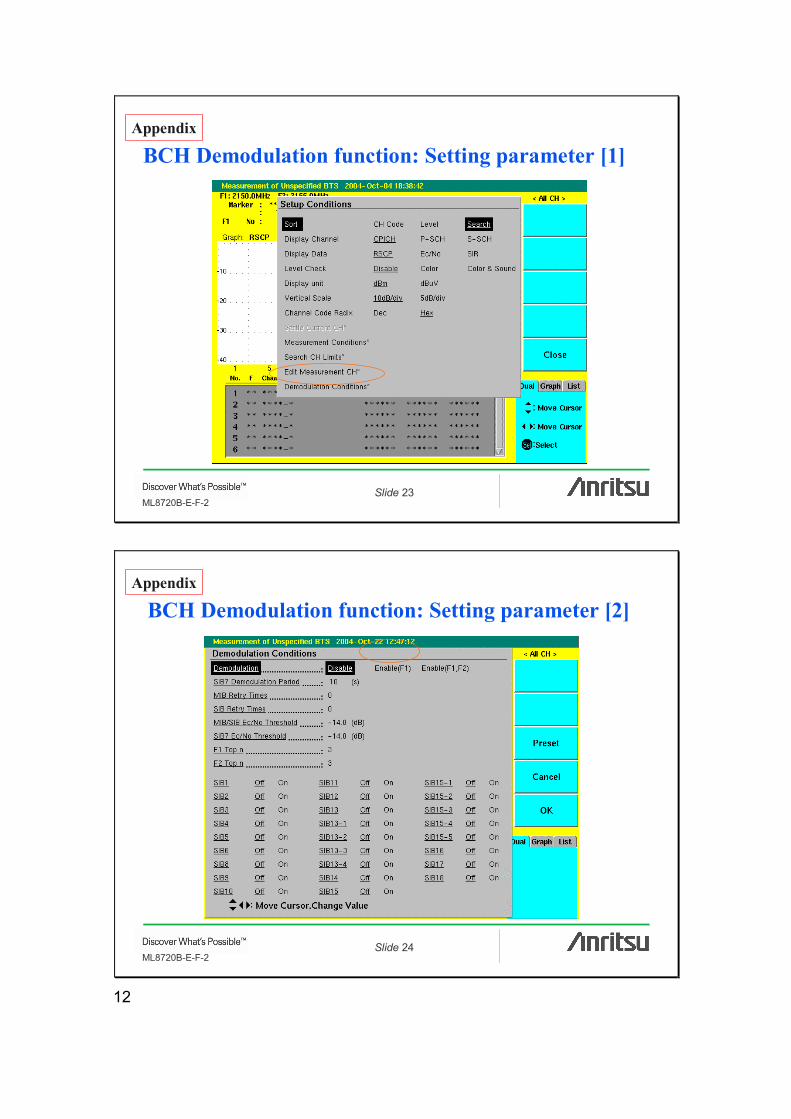
BCH Demodulation function: Setting parameter [1]Appendix
Slide 24ML8720B-E-F-2
BCH Demodulation function: Setting parameter [2]Appendix

13
Slide 25ML8720B-E-F-2
BCH Demodulation function: Display Image [1]
UL(dBm)Up-link Interference
The ‘V’ check mark means that demodulation is completed
Appendix
Slide 26ML8720B-E-F-2
BCH Demodulation function: Display Image [2]Appendix
14
Slide 27ML8720B-E-F-2
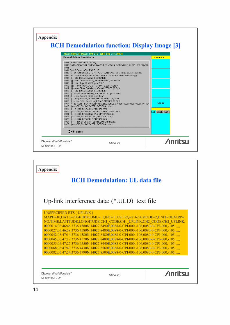
BCH Demodulation function: Display Image [3]Appendix
Slide 28ML8720B-E-F-2
BCH Demodulation: UL data file
UNSPECIFIED BTS ( UPLINK )MAPD=10,DATE=2004/10/06,DML= 1,INT=1.00S,FRQ=2162.4,MODE=2,UNIT=DBM,RP=NO,TIME,LATITUDE,LONGITUDE,CH1_CODE,CH1_UPLINK,CH2_CODE,CH2_UPLINK, 0000014,06:46:46,3736.4580N,14027.8490E,0088-0-CPI-000,-106,0080-0-CPI-000,-105,,,,,,0000027,06:46:59,3736.4580N,14027.8480E,0088-0-CPI-000,-106,0080-0-CPI-000,-105,,,,,,0000042,06:47:14,3736.4580N,14027.8480E,0088-0-CPI-000,-106,0080-0-CPI-000,-105,,,,,,0000045,06:47:17,3736.4570N,14027.8480E,0088-0-CPI-000,-106,0080-0-CPI-000,-105,,,,,,0000055,06:47:27,3736.4550N,14027.8440E,0088-0-CPI-000,-106,0080-0-CPI-000,-105,,,,,,0000068,06:47:40,3736.4430N,14027.8560E,0088-0-CPI-000,-106,0080-0-CPI-000,-105,,,,,,0000082,06:47:54,3736.3790N,14027.8500E,0088-0-CPI-000,-106,0080-0-CPI-000,-105,,,,,,
Up-link Interference data: (*.ULD) text file
Appendix
15
Slide 29ML8720B-E-F-2
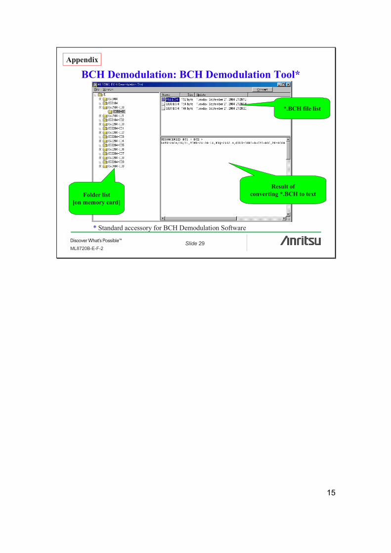
BCH Demodulation: BCH Demodulation Tool*
Folder list[on memory card]
*.BCH file list
Result ofconverting *.BCH to text
Appendix
* Standard accessory for BCH Demodulation Software

Confidential
No.ML8720B-E-F-2-(1.00) Printed in Japan 2005-7 AKD
ML8
720B
AP
PLI
CA
TIO
N N
OT
E
ANRITSU CORPORATION1800 Onna, Atsugi-shi, Kanagawa, 243-8555 JapanPhone: +81-46-223-1111Fax: +81-46-296-1264
• U.S.A.ANRITSU COMPANYTX OFFICE SALES AND SERVICE1155 East Collins Blvd., Richardson, TX 75081, U.S.A.Toll Free: 1-800-ANRITSU (267-4878)Phone: +1-972-644-1777Fax: +1-972-644-3416
• CanadaANRITSU ELECTRONICS LTD.700 Silver Seven Road, Suite 120, Kanata, ON K2V 1C3, CanadaPhone: +1-613-591-2003 Fax: +1-613-591-1006
• Brasil ANRITSU ELETRÔNICA LTDA.Praca Amadeu Amaral, 27 - 1 andar01327-010 - Paraiso, Sao Paulo, BrazilPhone: +55-11-3283-2511Fax: +55-11-3886940
• U.K.ANRITSU LTD.200 Capability Green, Luton, Bedfordshire LU1 3LU, U.K.Phone: +44-1582-433280 Fax: +44-1582-731303
• GermanyANRITSU GmbHGrafenberger Allee 54-56, 40237 Düsseldorf, Germany Phone: +49-211-96855-0 Fax: +49-211-96855-55
• FranceANRITSU S.A.9, Avenue du Québec Z.A. de Courtabœuf 91951 LesUlis Cedex, France Phone: +33-1-60-92-15-50Fax: +33-1-64-46-10-65
• ItalyANRITSU S.p.A.Via Elio Vittorini, 129, 00144 Roma EUR, ItalyPhone: +39-06-509-9711 Fax: +39-06-502-2425
• SwedenANRITSU ABBorgafjordsgatan 13 164 40 Kista, SwedenPhone: +46-853470700 Fax: +46-853470730
• FinlandANRITSU ABTeknobulevardi 3-5, FI-01530 Vantaa, FinlandPhone: +358-9-4355-220Fax: +358-9-4355-2250
• DenmarkAnritsu AB DanmarkKorskildelund 6 DK - 2670 Greve, DenmarkPhone: +45-36915035Fax: +45-43909371
• SingaporeANRITSU PTE LTD.10, Hoe Chiang Road #07-01/02, Keppel Towers,Singapore 089315 Phone: +65-6282-2400 Fax: +65-6282-2533
• Hong Kong ANRITSU COMPANY LTD.Suite 923, 9/F., Chinachem Golden Plaza, 77 ModyRoad, Tsimshatsui East, Kowloon, Hong Kong, ChinaPhone: +852-2301-4980Fax: +852-2301-3545
• P. R. ChinaANRITSU COMPANY LTD.Beijing Representative OfficeRoom 1515, Beijing Fortune Building, No. 5 NorthRoad, the East 3rd Ring Road, Chao-Yang DistrictBeijing 100004, P.R. ChinaPhone: +86-10-6590-9230
• KoreaANRITSU CORPORATION8F Hyun Juk Bldg. 832-41, Yeoksam-dong, Kangnam-ku, Seoul, 135-080, KoreaPhone: +82-2-553-6603Fax: +82-2-553-6604
• AustraliaANRITSU PTY LTD.Unit 3/170 Forster Road Mt. Waverley, Victoria, 3149,AustraliaPhone: +61-3-9558-8177Fax: +61-3-9558-8255
• TaiwanANRITSU COMPANY INC.7F, No. 316, Sec. 1, NeiHu Rd., Taipei, TaiwanPhone: +886-2-8751-1816Fax: +886-2-8751-1817
Specifications are subject to change without notice.
050203
Printed on 100% Recycled Paper


