24
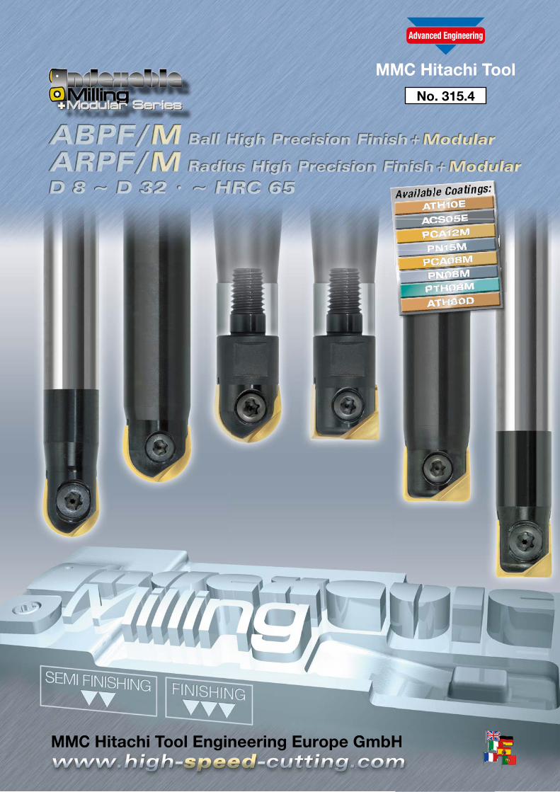
No. 315.4
No. 315.4
Indexable Milling Tools
2
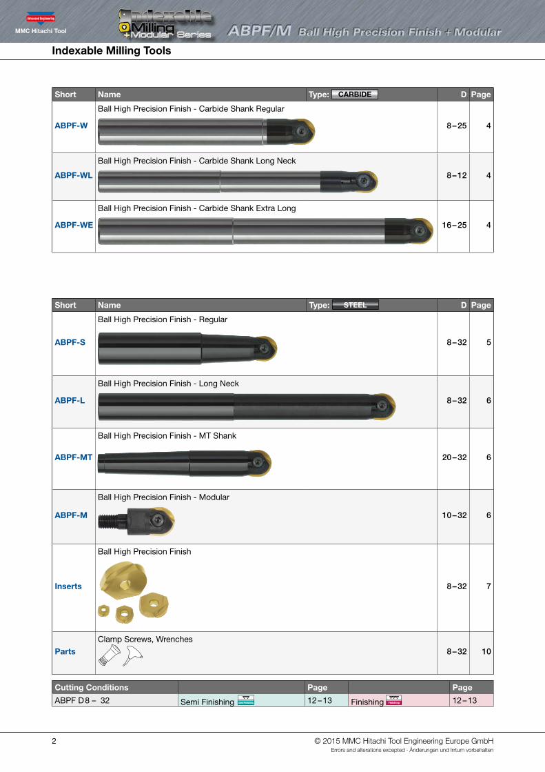
Short Name Type: CARBIDE D Page
ABPF-W
Ball High Precision Finish - Carbide Shank Regular
8 – 25 4
ABPF-WL
Ball High Precision Finish - Carbide Shank Long Neck
8 – 12 4
ABPF-WE
Ball High Precision Finish - Carbide Shank Extra Long
16 – 25 4
Short Name Type: STEEL D Page
ABPF-S
Ball High Precision Finish - Regular
8 – 32 5
ABPF-L
Ball High Precision Finish - Long Neck
8 – 32 6
ABPF-MT
Ball High Precision Finish - MT Shank
20 – 32 6
ABPF-M
Ball High Precision Finish - Modular
10 – 32 6
Inserts
Ball High Precision Finish
8 – 32 7
PartsClamp Screws, Wrenches
8 – 32 10
Cutting Conditions Page Page
ABPF D 8 – 32 Semi Finishing Semi Finishing 12 – 13 Finishing Finishing 12 – 13
© 2015 MMC Hitachi Tool Engineering Europe GmbHErrors and alterations excepted · Änderungen und Irrtum vorbehalten
Indexable Milling Tools
3
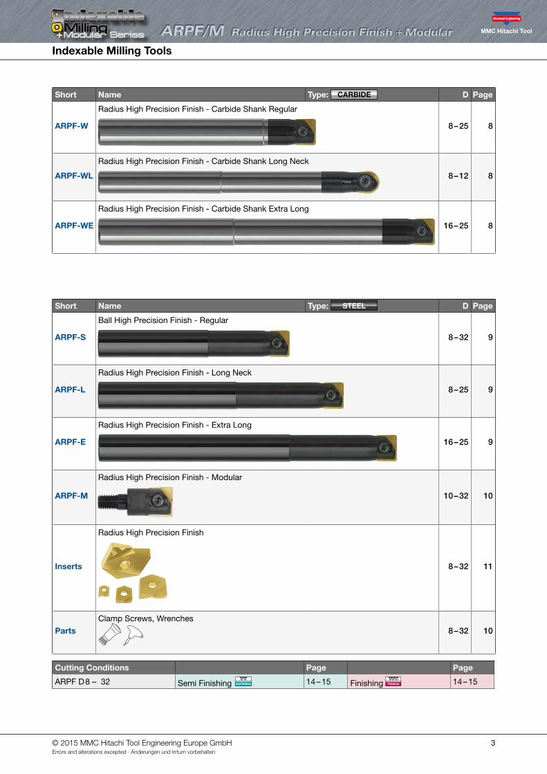
Short Name Type: CARBIDE D Page
ARPF-W
Radius High Precision Finish - Carbide Shank Regular
8 – 25 8
ARPF-WL
Radius High Precision Finish - Carbide Shank Long Neck
8 – 12 8
ARPF-WE
Radius High Precision Finish - Carbide Shank Extra Long
16 – 25 8
Short Name Type: STEEL D Page
ARPF-S
Ball High Precision Finish - Regular
8 – 32 9
ARPF-L
Radius High Precision Finish - Long Neck
8 – 25 9
ARPF-E
Radius High Precision Finish - Extra Long
16 – 25 9
ARPF-M
Radius High Precision Finish - Modular
10 – 32 10
Inserts
Radius High Precision Finish
8 – 32 11
PartsClamp Screws, Wrenches
8 – 32 10
Cutting Conditions Page Page
ARPF D 8 – 32 Semi Finishing Semi Finishing 14 – 15 Finishing Finishing 14 – 15
© 2015 MMC Hitachi Tool Engineering Europe GmbHErrors and alterations excepted · Änderungen und Irrtum vorbehalten
Indexable Milling Tools
4
V maxHigh Speed
HRC65Semi Finishing
No. of Teeth
2Finishing
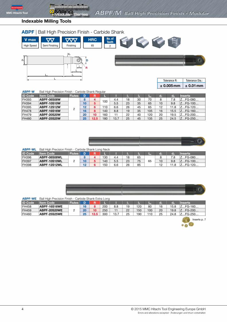
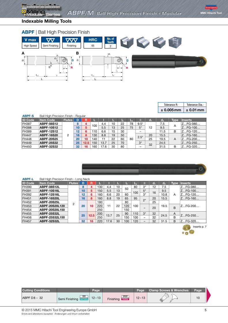
ABPF | Ball High Precision Finish - Carbide Shank
ABPF-W Ball High Precision Finish - Carbide Shank RegularID Code Item Code Flutes D R L I l1 l2 Ls d1 d2 InsertsFH393 ABPF-08S08W
2
8 4100
4.4 18 30 70 8 7.8 Z…FG-080…FH394 ABPF-10S10W 10 5 5.5 23 35 65 10 9.8 Z…FG-100…FH395 ABPF-12S12W 12 6 110 6.6 26 45 65 12 11.8 Z…FG-120…FH478 ABPF-16S16W 16 8 140 8.8 19 35 105 16 15.5 Z…FG-160…FH479 ABPF-20S20W 20 10 160 11 22 40 120 20 19.5 Z…FG-200…FH480 ABPF-25S25W 25 12.5 180 13.7 25 45 135 25 24.5 Z…FG-250…
ABPF-WL Ball High Precision Finish - Carbide Shank Long Neck ID Code Item Code Flutes D R L I l1 l2 Ls d1 d2 InsertsFH396 ABPF-08S08WL
28 4 130 4.4 18 65
658 7.8 Z…FG-080…
FH397 ABPF-10S10WL 10 5 140 5.5 23 75 10 9.8 Z…FG-100…FH398 ABPF-12S12WL 12 6 150 6.6 26 85 12 11.8 Z…FG-120…
ABPF-WE Ball High Precision Finish - Carbide Shank Extra Long ID Code Item Code Flutes D R L I l1 l2 Ls d1 d2 InsertsFH458 ABPF-16S16WE
216 8 200 8.8 19 120 80 16 15.8 Z…FG-160…
FH459 ABPF-20S20WE 20 10 250 11 22 150 100 20 19.8 Z…FG-200…FH460 ABPF-25S25WE 25 12.5 300 13.7 25 190 110 25 24.8 Z…FG-250…
Inserts p. 7
d1
l1
l
d2
L
l2Ls
D
θ R
d1
l1
l
d2
Ll2Ls
D
R
Tolerance R: Tolerance Dia.:
± 0.005 mm ± 0.01 mm
© 2015 MMC Hitachi Tool Engineering Europe GmbHErrors and alterations excepted · Änderungen und Irrtum vorbehalten
Indexable Milling Tools
5
ABPF-S Ball High Precision Finish - Regular ID Code Item Code Flutes D R L I l1 l2 Ls θ d1 d2 Type InsertsFH387 ABPF-08S12
2
8 4100
4.4 10 22 78 9.5°12
7.5A
Z…FG-080…FH388 ABPF-10S12 10 5 5.5 13 25 75 5° 9.5 Z…FG-100…FH389 ABPF-12S12 12 6 110 6.6 15 30
80
– 11.5 B Z…FG-120…FH447 ABPF-16S20 16 8 130 8.8 19 50
2.5°20 15.5
AZ…FG-160…
FH448 ABPF-20S25 20 10 140 11 22 60 25 19.5 Z…FG-200…FH449 ABPF-25S32 25 12.5 150 13.7 25 70 3°
3224.5 Z…FG-250…
FH450 ABPF-32S32 32 16 160 17.6 30 80 – 31.5 B Z…FG-320…
ABPF | Ball High Precision Finish
V maxHigh Speed
HRC65Semi Finishing
No. of Teeth
2Finishing
ABPF-L Ball High Precision Finish - Long NeckID Code Item Code Flutes D R L I l1 l2 Ls θ d1 d2 Type InsertsFH390 ABPF-08S12L
2
8 4 130 4.4 1050
80 3° 12 7.5
A
Z…FG-080…FH391 ABPF-10S16L 10 5 150 5.5 13
1005°
169.5 Z…FG-100…
FH392 ABPF-12S16L 12 6 160 6.6 20 60 3° 10.8 Z…FG-120…FH451 ABPF-16S20L 16 8 160 8.8 19 65 95
2°20 15.5 Z…FG-160…
FH452 ABPF-20S25L20 10
18011 22
80100
2519.5 Z…FG-200…FH453 ABPF-20S20L120 220 120
– 20 BFH454 ABPF-20S20L150 250 150FH455 ABPF-25S32L
25 12.5200
13.7 2590 110 3° 32
24.5A
Z…FG-250…FH456 ABPF-25S32L150 250 150 100 – 32 BFH457 ABPF-32S32L 32 16 220 17.6 30 100 120 – 32 31.5 B Z…FG-320…
Inserts p. 7
A B
d1
l1
l
d2
Ll2
D
R
Ls
l1
l
d2
L
l2
D
θ R
d1
Lss
Tolerance R: Tolerance Dia.:
± 0.005 mm ± 0.01 mm
Cutting Conditions Page Page Clamp Screws & Wrenches Page
ABPF D 8 – 32 Semi Finishing Semi Finishing 12 – 13 Finishing Finishing 12 – 13
10
© 2015 MMC Hitachi Tool Engineering Europe GmbHErrors and alterations excepted · Änderungen und Irrtum vorbehalten
Indexable Milling Tools
6
V maxHigh Speed
HRC65Semi Finishing
No. of Teeth
2Finishing
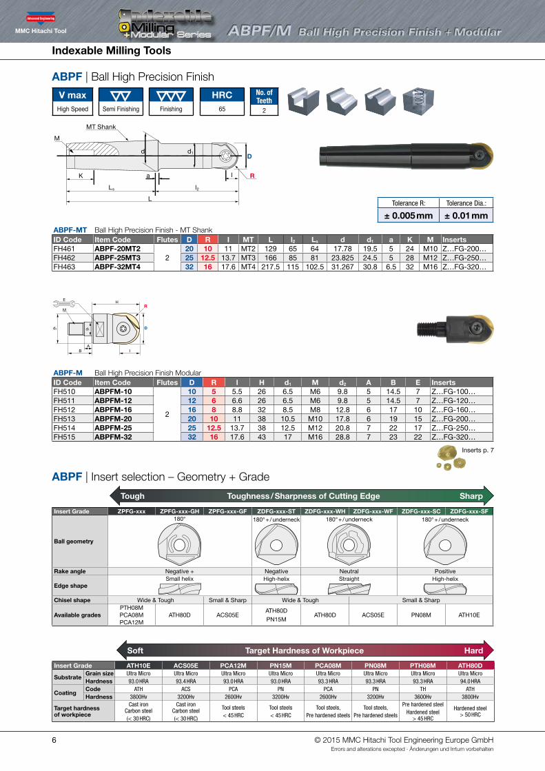
ABPF | Ball High Precision Finish
ABPF | Insert selection – Geometry + Grade
ABPF-MT Ball High Precision Finish - MT Shank ID Code Item Code Flutes D R I MT L l2 Ls d d1 a K M InsertsFH461 ABPF-20MT2
220 10 11 MT2 129 65 64 17.78 19.5 5 24 M10 Z…FG-200…
FH462 ABPF-25MT3 25 12.5 13.7 MT3 166 85 81 23.825 24.5 5 28 M12 Z…FG-250…FH463 ABPF-32MT4 32 16 17.6 MT4 217.5 115 102.5 31.267 30.8 6.5 32 M16 Z…FG-320…
ABPF-M Ball High Precision Finish ModularID Code Item Code Flutes D R l H d1 M d2 A B E InsertsFH510 ABPFM-10
2
10 5 5.5 26 6.5 M6 9.8 5 14.5 7 Z…FG-100…FH511 ABPFM-12 12 6 6.6 26 6.5 M6 9.8 5 14.5 7 Z…FG-120…FH512 ABPFM-16 16 8 8.8 32 8.5 M8 12.8 6 17 10 Z…FG-160…FH513 ABPFM-20 20 10 11 38 10.5 M10 17.8 6 19 15 Z…FG-200…FH514 ABPFM-25 25 12.5 13.7 38 12.5 M12 20.8 7 22 17 Z…FG-250…FH515 ABPFM-32 32 16 17.6 43 17 M16 28.8 7 23 22 Z…FG-320…
Inserts p. 7
d1
H
AB I
d2 D
RE
M
d
MT Shank
M
K a l
d1
L
D
R
l2Ls
Insert Grade ATH10E ACS05E PCA12M PN15M PCA08M PN08M PTH08M ATH80D
SubstrateGrain size Ultra Micro Ultra Micro Ultra Micro Ultra Micro Ultra Micro Ultra Micro Ultra Micro Ultra MicroHardness 93.0 HRA 93.4 HRA 93.0 HRA 93.0 HRA 93.3 HRA 93.3 HRA 93.3 HRA 94.0 HRA
CoatingCode ATH ACS PCA PN PCA PN TH ATHHardness 3800Hv 3200Hv 2600Hv 3200Hv 2600Hv 3200Hv 3600Hv 3800Hv
Target hardness of workpiece
Cast ironCarbon steel(< 30 HRC)
Cast ironCarbon steel(< 30 HRC)
Tool steels< 45 HRC
Tool steels< 45 HRC
Tool steels, Pre hardened steels
Tool steels, Pre hardened steels
Pre hardened steel Hardened steel
> 45 HRC
Hardened steel > 50 HRC
Insert Grade ZPFG-xxx ZPFG-xxx-GH ZPFG-xxx-GF ZDFG-xxx-ST ZDFG-xxx-WH ZDFG-xxx-WF ZDFG-xxx-SC ZDFG-xxx-SF
Ball geometry
180° 180° + / underneck 180° + / underneck 180° + / underneck
Rake angle Negative + Negative Neutral Positive
Edge shapeSmall helix High-helix Straight High-helix
Chisel shape Wide & Tough Small & Sharp Wide & Tough Small & Sharp
Available gradesPTH08MPCA08MPCA12M
ATH80D ACS05EATH80DPN15M
ATH80D ACS05E PN08M ATH10E
Soft Target Hardness of Workpiece Hard
Tough Toughness / Sharpness of Cutting Edge Sharp
Tolerance R: Tolerance Dia.:
± 0.005 mm ± 0.01 mm
© 2015 MMC Hitachi Tool Engineering Europe GmbHErrors and alterations excepted · Änderungen und Irrtum vorbehalten
7
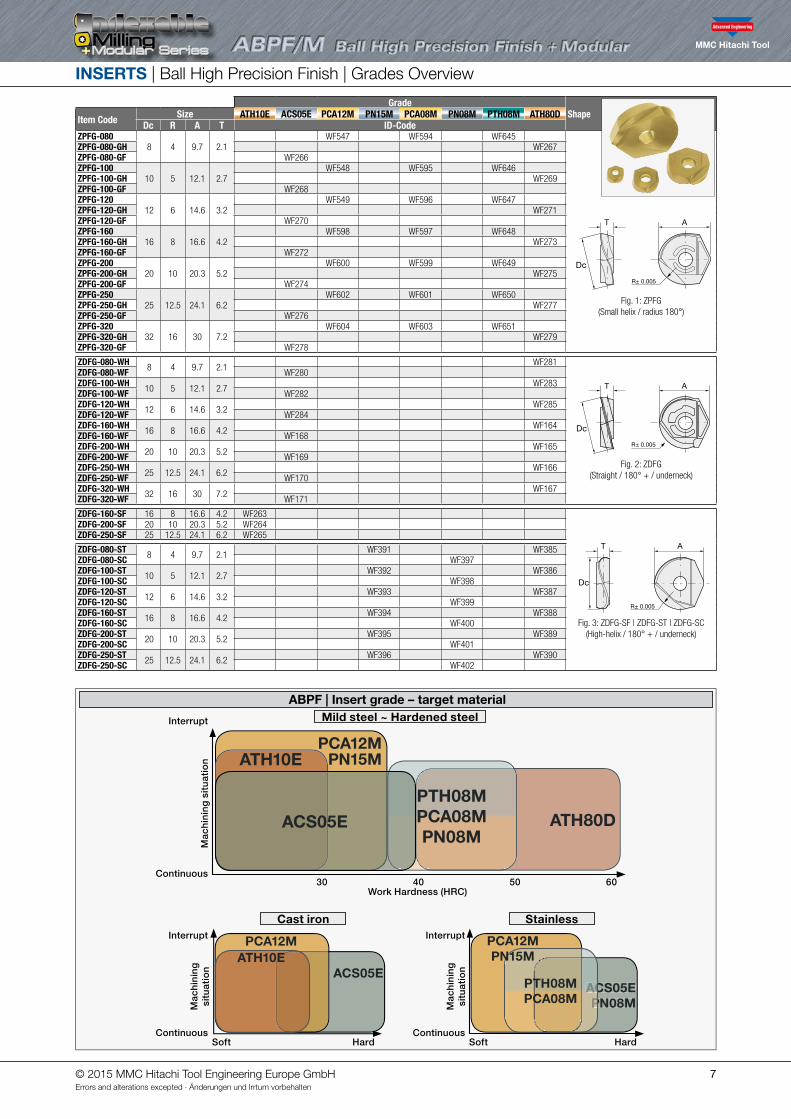
INSERTS | Ball High Precision Finish | Grades Overview
GradeShapeItem Code Size ATH10E ACS05E PCA12M PN15M PCA08M PN08M PTH08M ATH80D
Dc R A T ID-CodeZPFG-080
8 4 9.7 2.1WF547 WF594 WF645
Dc
Fig. 1: ZPFG(Small helix / radius 180°)
ZPFG-080-GH WF267ZPFG-080-GF WF266ZPFG-100
10 5 12.1 2.7WF548 WF595 WF646
ZPFG-100-GH WF269ZPFG-100-GF WF268ZPFG-120
12 6 14.6 3.2WF549 WF596 WF647
ZPFG-120-GH WF271ZPFG-120-GF WF270ZPFG-160
16 8 16.6 4.2WF598 WF597 WF648
ZPFG-160-GH WF273ZPFG-160-GF WF272ZPFG-200
20 10 20.3 5.2WF600 WF599 WF649
ZPFG-200-GH WF275ZPFG-200-GF WF274ZPFG-250
25 12.5 24.1 6.2WF602 WF601 WF650
ZPFG-250-GH WF277ZPFG-250-GF WF276ZPFG-320
32 16 30 7.2WF604 WF603 WF651
ZPFG-320-GH WF279ZPFG-320-GF WF278
ZDFG-080-WH 8 4 9.7 2.1 WF281
Dc
Fig. 2: ZDFG(Straight / 180° + / underneck)
ZDFG-080-WF WF280ZDFG-100-WH 10 5 12.1 2.7 WF283ZDFG-100-WF WF282ZDFG-120-WH 12 6 14.6 3.2 WF285ZDFG-120-WF WF284ZDFG-160-WH 16 8 16.6 4.2 WF164ZDFG-160-WF WF168ZDFG-200-WH 20 10 20.3 5.2 WF165ZDFG-200-WF WF169ZDFG-250-WH 25 12.5 24.1 6.2 WF166ZDFG-250-WF WF170ZDFG-320-WH 32 16 30 7.2 WF167ZDFG-320-WF WF171
ZDFG-160-SF 16 8 16.6 4.2 WF263
Dc
Fig. 3: ZDFG-SF | ZDFG-ST | ZDFG-SC(High-helix / 180° + / underneck)
ZDFG-200-SF 20 10 20.3 5.2 WF264ZDFG-250-SF 25 12.5 24.1 6.2 WF265
ZDFG-080-ST 8 4 9.7 2.1 WF391 WF385ZDFG-080-SC WF397ZDFG-100-ST 10 5 12.1 2.7 WF392 WF386ZDFG-100-SC WF398ZDFG-120-ST 12 6 14.6 3.2 WF393 WF387ZDFG-120-SC WF399ZDFG-160-ST 16 8 16.6 4.2 WF394 WF388ZDFG-160-SC WF400ZDFG-200-ST 20 10 20.3 5.2 WF395 WF389ZDFG-200-SC WF401ZDFG-250-ST 25 12.5 24.1 6.2 WF396 WF390ZDFG-250-SC WF402
ABPF | Insert grade – target material
ATH80DPTH08MPCA08MPN08M
ATH10E
Mild steel ~ Hardened steel
Cast iron
Continuous
Continuous
Work Hardness (HRC)30 40 50 60
Mac
hin
ing
sit
uat
ion
Mac
hin
ing
si
tuat
ion
Interrupt
Interrupt
HardSoft
Stainless
ContinuousHardSoft
Mac
hin
ing
si
tuat
ion
Interrupt
ACS05E
ACS05EACS05EPN08M
PCA12MATH10E
ACS05EPN08M
PTH08MPCA08M
PCA12MPN15M
PCA12MPN15M
© 2015 MMC Hitachi Tool Engineering Europe GmbHErrors and alterations excepted · Änderungen und Irrtum vorbehalten
Indexable Milling Tools
8
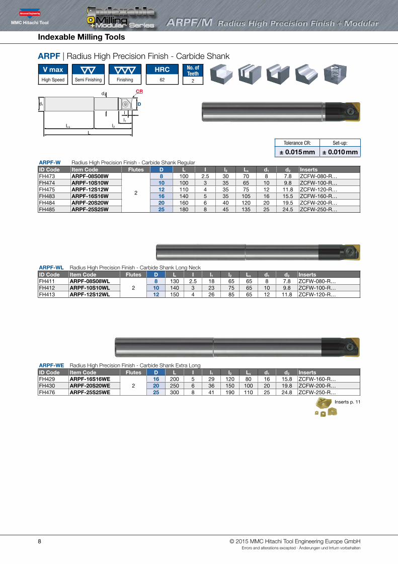
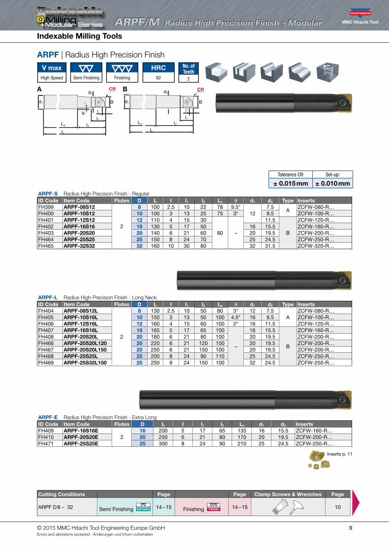
Tolerance CR: Set-up:
± 0.015 mm ± 0.010 mm
ARPF-W Radius High Precision Finish - Carbide Shank RegularID Code Item Code Flutes D L I l2 Ls d1 d2 InsertsFH473 ARPF-08S08W
2
8 100 2.5 30 70 8 7.8 ZCFW-080-R…FH474 ARPF-10S10W 10 100 3 35 65 10 9.8 ZCFW-100-R…FH475 ARPF-12S12W 12 110 4 35 75 12 11.8 ZCFW-120-R…FH483 ARPF-16S16W 16 140 5 35 105 16 15.5 ZCFW-160-R…FH484 ARPF-20S20W 20 160 6 40 120 20 19.5 ZCFW-200-R…FH485 ARPF-25S25W 25 180 8 45 135 25 24.5 ZCFW-250-R…
Semi Finishing Finishing
ARPF-WE Radius High Precision Finish - Carbide Shank Extra LongID Code Item Code Flutes D L I l1 l2 Ls d1 d2 InsertsFH429 ARPF-16S16WE
216 200 5 29 120 80 16 15.8 ZCFW-160-R…
FH430 ARPF-20S20WE 20 250 6 36 150 100 20 19.8 ZCFW-200-R…FH476 ARPF-25S25WE 25 300 8 41 190 110 25 24.8 ZCFW-250-R…
Inserts p. 11
ARPF-WL Radius High Precision Finish - Carbide Shank Long NeckID Code Item Code Flutes D L I l1 l2 Ls d1 d2 InsertsFH411 ARPF-08S08WL
28 130 2.5 18 65 65 8 7.8 ZCFW-080-R…
FH412 ARPF-10S10WL 10 140 3 23 75 65 10 9.8 ZCFW-100-R…FH413 ARPF-12S12WL 12 150 4 26 85 65 12 11.8 ZCFW-120-R…
V maxHigh Speed
HRC62
No. of Teeth
2
ARPF | Radius High Precision Finish - Carbide Shank
d1
l1
l
d2
L
D
CR
l2Ls
© 2015 MMC Hitachi Tool Engineering Europe GmbHErrors and alterations excepted · Änderungen und Irrtum vorbehalten
Indexable Milling Tools
9
Tolerance CR: Set-up:
± 0.015 mm ± 0.010 mm
ARPF-E Radius High Precision Finish - Extra LongID Code Item Code Flutes D L I l1 l2 Ls d1 d2 InsertsFH409 ARPF-16S16E
216 200 5 17 65 135 16 15.5 ZCFW-160-R…
FH410 ARPF-20S20E 20 250 6 21 80 170 20 19.5 ZCFW-200-R…FH471 ARPF-25S25E 25 300 8 24 90 210 25 24.5 ZCFW-250-R…
Inserts p. 11
ARPF-S Radius High Precision Finish - Regular ID Code Item Code Flutes D L I l1 l2 Ls θ d1 d2 Type InsertsFH399 ARPF-08S12
2
8 100 2.5 10 22 78 9.5°12
7.5A
ZCFW-080-R…FH400 ARPF-10S12 10 100 3 13 25 75 3° 9.5 ZCFW-100-R…FH401 ARPF-12S12 12 110 4 15 30
80 –
11.5
B
ZCFW-120-R…FH402 ARPF-16S16 16 130 5 17 50 16 15.5 ZCFW-160-R…FH403 ARPF-20S20 20 140 6 21 60 20 19.5 ZCFW-200-R…FH464 ARPF-25S25 25 150 8 24 70 25 24.5 ZCFW-250-R…FH465 ARPF-32S32 32 160 10 30 80 32 31.5 ZCFW-320-R…
V maxHigh Speed
HRC62Semi Finishing Finishing
No. of Teeth
2
ARPF | Radius High Precision Finish
d1
l1
l
d2
D
CR
θ
Ll2Ls
d1
l1
l
d2
D
CR
θ
Ll2Ls
ARPF-L Radius High Precision Finish - Long NeckID Code Item Code Flutes D L I l1 l2 Ls θ d1 d2 Type InsertsFH404 ARPF-08S12L
2
8 130 2.5 10 50 80 3° 12 7.5A
ZCFW-080-R…FH405 ARPF-10S16L 10 150 3 13 50 100 4.5° 16 9.5 ZCFW-100-R…FH406 ARPF-12S16L 12 160 4 15 60 100 2° 16 11.5 ZCFW-120-R…FH407 ARPF-16S16L 16 165 5 17 65 100
–
16 15.5
B
ZCFW-160-R…FH408 ARPF-20S20L 20 180 6 21 80 100 20 19.5 ZCFW-200-R…FH466 ARPF-20S20L120 20 220 6 21 120 100 20 19.5 ZCFW-200-R…FH467 ARPF-20S20L150 20 250 6 21 150 100 20 19.5 ZCFW-200-R…FH468 ARPF-25S25L 25 200 8 24 90 110 25 24.5 ZCFW-250-R…FH469 ARPF-25S32L150 25 250 8 24 150 100 32 24.5 ZCFW-250-R…
A B
d1
l1
l
d2
L
D
CR
l2Ls
d1
l1
l
d2
L
D
CR
l2Ls
d1
l1
l
d2
L
D
CR
l2Ls
d1
l1
l
d2
L
D
CR
l2Ls
d1
l1
l
d2
L
D
CR
l2Ls
Cutting Conditions Page Page Clamp Screws & Wrenches Page
ARPF D 8 – 32 Semi Finishing Semi Finishing 14 – 15 Finishing Finishing 14 – 15
10
© 2015 MMC Hitachi Tool Engineering Europe GmbHErrors and alterations excepted · Änderungen und Irrtum vorbehalten

Indexable Milling Tools
10
d1
H
AB I
d2 D
CRM
E
ARPF | Radius High Precision Finish
V maxHigh Speed
HRC62Semi Finishing Finishing
No. of Teeth
2
Parts
Clamp Screw Wrench
Body Diameter ID-Code Item-Code Tightening torque ID-Code Item-Code
ABPF-… / ABPFM-…
ARPF-… / ARPFM-…
8 ET153 581-141 1.5 Nm ET13 104-T810 ET154 581-142 2.0 Nm ET11 104-T1012 ET155 581-143 5.0 Nm
ET14 105-T2016 ET156 581-144 5.0 Nm20 ET157 581-145 7.0 Nm ET9 101-T25S25 ET168 581-146 7.0 Nm
ET167 105-T30A32 ET169 581-147 7.0 Nm
ARPF-M Radius High Precision Finish ModularID Code Item Code Flutes D l H d1 M d2 A B E InsertsFH516 ARPFM-10
2
10 326 6.5 M6 9.8 5 14.5 7
ZCFW-100-R…FH517 ARPFM-12 12 4 ZCFW-120-R…FH518 ARPFM-16 16 5 32 8.5 M8 12.8
617 10 ZCFW-160-R…
FH519 ARPFM-20 20 638
10.5 M10 17.8 19 15 ZCFW-200-R…FH520 ARPFM-25 25 8 12.5 M12 20.8
722 17 ZCFW-250-R…
FH521 ARPFM-32 32 10 43 17 M16 28.8 23 22 ZCFW-320-R…
Inserts p. 11
Tolerance CR: Set-up:
± 0.015 mm ± 0.010 mm
Cutting Conditions Page Page
ARPF D 8 – 32 Semi Finishing Semi Finishing 14 – 15 Finishing Finishing 14 – 15
© 2015 MMC Hitachi Tool Engineering Europe GmbHErrors and alterations excepted · Änderungen und Irrtum vorbehalten
11
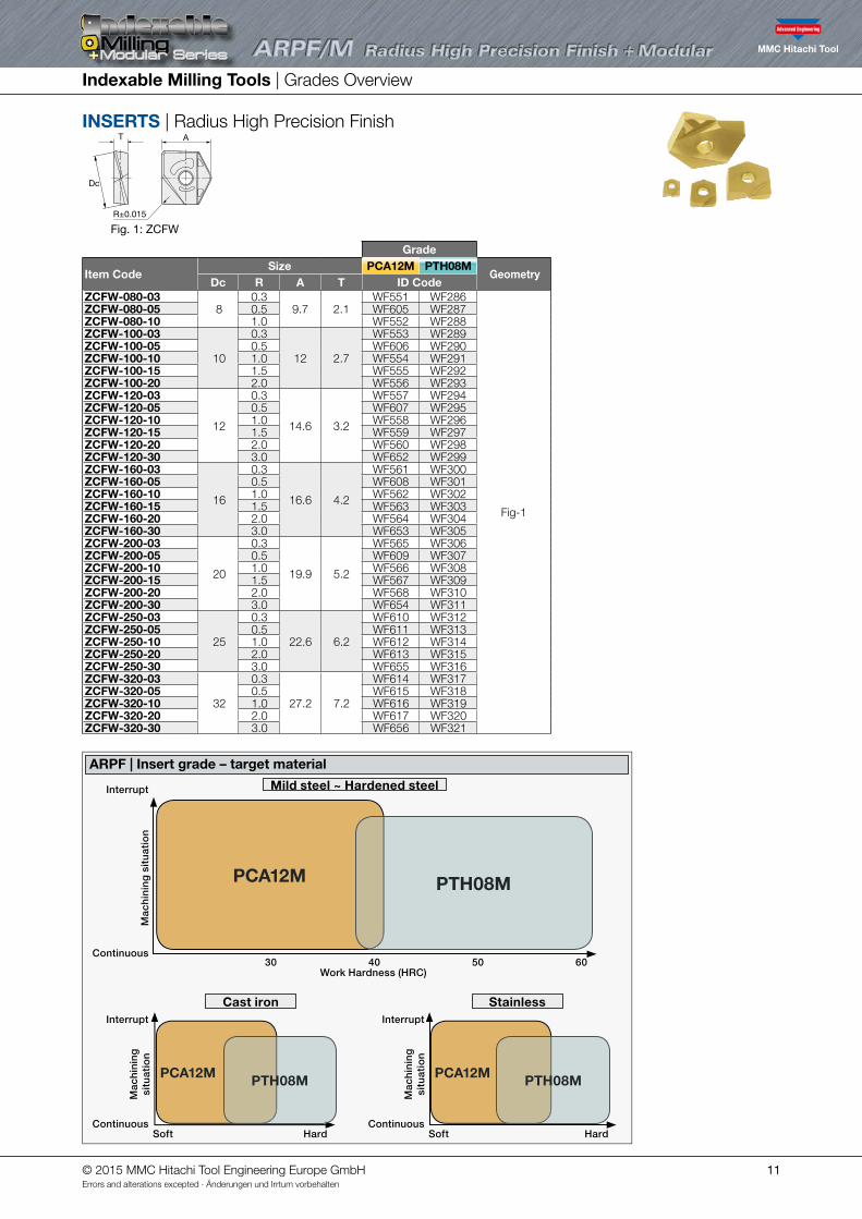
INSERTS | Radius High Precision Finish
Indexable Milling Tools | Grades Overview
Fig. 1: ZCFW
Grade
Item CodeSize PCA12M PTH08M
GeometryDc R A T ID Code
ZCFW-080-038
0.39.7 2.1
WF551 WF286
Fig-1
ZCFW-080-05 0.5 WF605 WF287ZCFW-080-10 1.0 WF552 WF288ZCFW-100-03
10
0.3
12 2.7
WF553 WF289ZCFW-100-05 0.5 WF606 WF290ZCFW-100-10 1.0 WF554 WF291ZCFW-100-15 1.5 WF555 WF292ZCFW-100-20 2.0 WF556 WF293ZCFW-120-03
12
0.3
14.6 3.2
WF557 WF294ZCFW-120-05 0.5 WF607 WF295ZCFW-120-10 1.0 WF558 WF296ZCFW-120-15 1.5 WF559 WF297ZCFW-120-20 2.0 WF560 WF298ZCFW-120-30 3.0 WF652 WF299ZCFW-160-03
16
0.3
16.6 4.2
WF561 WF300ZCFW-160-05 0.5 WF608 WF301ZCFW-160-10 1.0 WF562 WF302ZCFW-160-15 1.5 WF563 WF303ZCFW-160-20 2.0 WF564 WF304ZCFW-160-30 3.0 WF653 WF305ZCFW-200-03
20
0.3
19.9 5.2
WF565 WF306ZCFW-200-05 0.5 WF609 WF307ZCFW-200-10 1.0 WF566 WF308ZCFW-200-15 1.5 WF567 WF309ZCFW-200-20 2.0 WF568 WF310ZCFW-200-30 3.0 WF654 WF311ZCFW-250-03
25
0.3
22.6 6.2
WF610 WF312ZCFW-250-05 0.5 WF611 WF313ZCFW-250-10 1.0 WF612 WF314ZCFW-250-20 2.0 WF613 WF315ZCFW-250-30 3.0 WF655 WF316ZCFW-320-03
32
0.3
27.2 7.2
WF614 WF317ZCFW-320-05 0.5 WF615 WF318ZCFW-320-10 1.0 WF616 WF319ZCFW-320-20 2.0 WF617 WF320ZCFW-320-30 3.0 WF656 WF321
A
R±0.015
Dc
T
ARPF | Insert grade – target material
Mild steel ~ Hardened steel
Cast iron
Continuous
Continuous
Work Hardness (HRC)30 40 50 60
Mac
hin
ing
sit
uat
ion
Mac
hin
ing
si
tuat
ion
Interrupt
Interrupt
HardSoft
Stainless
ContinuousHardSoft
Mac
hin
ing
si
tuat
ion
Interrupt
PCA12M
PCA12M PCA12M
PTH08M
PTH08M PTH08M
© 2015 MMC Hitachi Tool Engineering Europe GmbHErrors and alterations excepted · Änderungen und Irrtum vorbehalten

12
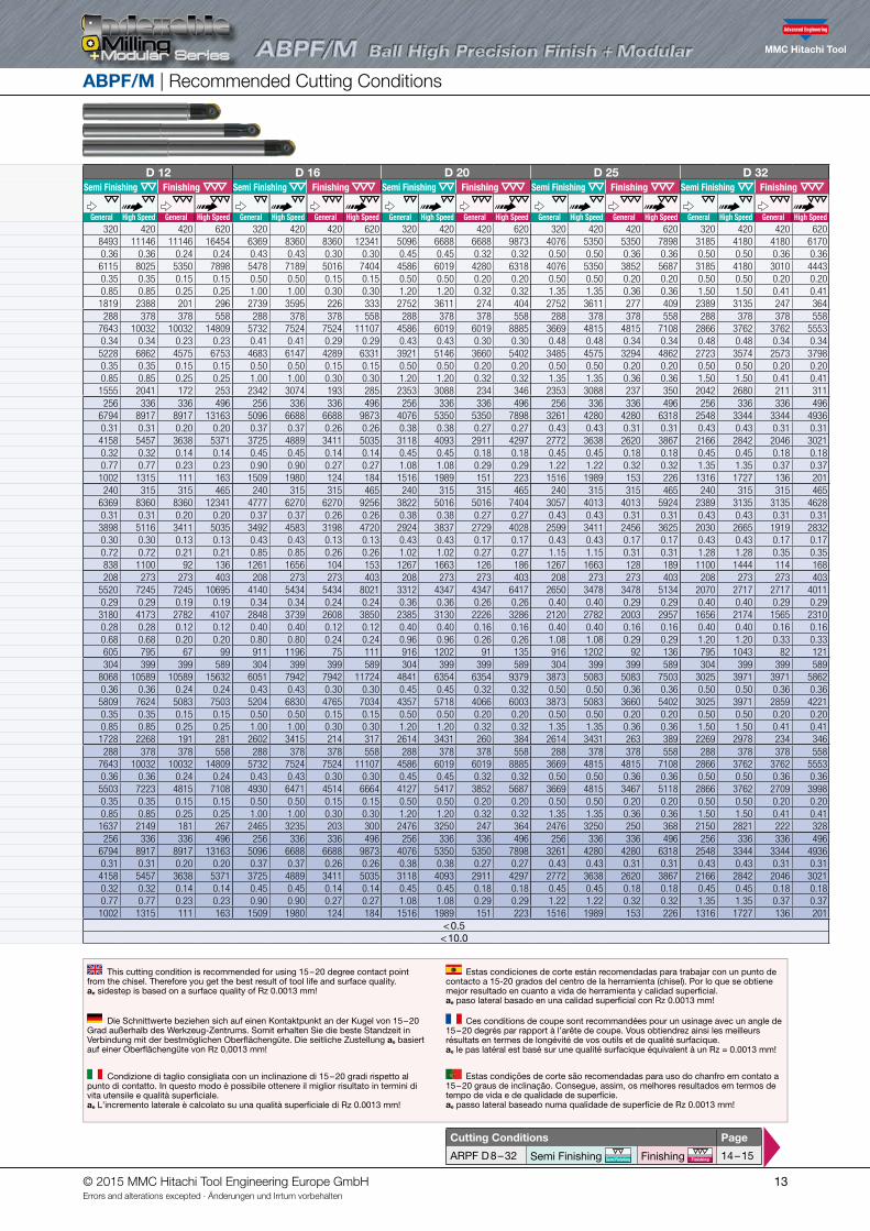
ABPF/M | Recommended Cutting Conditions
Work piece materialv
Insert Grade Recommend grade & Target hardness (HRC)
Emul
sion
Mis
tAi
r
Para meter
D 8 D 10 D 12 D 16 D 20 D 25 D 32Semi Finishing Finishing Semi Finishing Finishing Semi Finishing Finishing Semi Finishing Finishing Semi Finishing Finishing Semi Finishing Finishing Semi Finishing Finishing
Semi Finishing Finishing 30 40 50General High Speed General High Speed General High Speed General High Speed General High Speed General High Speed General High Speed General High Speed General High Speed General High Speed General High Speed General High Speed General High Speed General High Speed
III
Carbon-SteelAlloy-Steel<30HRC
PCA08M PCA12M PN15M
ACS05E PTH08M PN08M ATH10E
ACS05E • • • Vc m/min 320 420 420 620 320 420 420 620 320 420 420 620 320 420 420 620 320 420 420 620 320 420 420 620 320 420 420 620PCA12M • • • n min-1 12739 16720 16720 24682 10191 13376 13376 19745 8493 11146 11146 16454 6369 8360 8360 12341 5096 6688 6688 9873 4076 5350 5350 7898 3185 4180 4180 6170
PCA08M • • • fz mm/t 0.20 0.18 0.15 0.15 0.30 0.30 0.21 0.21 0.36 0.36 0.24 0.24 0.43 0.43 0.30 0.30 0.45 0.45 0.32 0.32 0.50 0.50 0.36 0.36 0.50 0.50 0.36 0.36PTH08M • • • Vf mm/min 5096 6019 5016 7404 6115 8025 5618 8293 6115 8025 5350 7898 5478 7189 5016 7404 4586 6019 4280 6318 4076 5350 3852 5687 3185 4180 3010 4443
PN15M • • • ap mm 0.20 0.20 0.10 0.10 0.35 0.35 0.10 0.10 0.35 0.35 0.15 0.15 0.50 0.50 0.15 0.15 0.50 0.50 0.20 0.20 0.50 0.50 0.20 0.20 0.50 0.50 0.20 0.20PN08M • • • ae mm 0.80 0.80 0.20 0.20 0.70 0.70 0.22 0.22 0.85 0.85 0.25 0.25 1.00 1.00 0.30 0.30 1.20 1.20 0.32 0.32 1.35 1.35 0.36 0.36 1.50 1.50 0.41 0.41
ATH10E • • • Q mm3 815 963 100 148 1498 1966 124 182 1819 2388 201 296 2739 3595 226 333 2752 3611 274 404 2752 3611 277 409 2389 3135 247 364
IIIAlloy-SteelTool-Steel30~40HRC
PCA08M PCA12M PN15M
ACS05E PTH08M PN08M
ACS05E • • • Vc m/min 288 378 378 558 288 378 378 558 288 378 378 558 288 378 378 558 288 378 378 558 288 378 378 558 288 378 378 558PCA12M • • • n min-1 11465 15048 15048 22213 9172 12038 12038 17771 7643 10032 10032 14809 5732 7524 7524 11107 4586 6019 6019 8885 3669 4815 4815 7108 2866 3762 3762 5553
PCA08M • • • fz mm/t 0.19 0.17 0.14 0.14 0.29 0.29 0.20 0.20 0.34 0.34 0.23 0.23 0.41 0.41 0.29 0.29 0.43 0.43 0.30 0.30 0.48 0.48 0.34 0.34 0.48 0.48 0.34 0.34PTH08M • • • Vf mm/min 4357 5146 4289 6331 5228 6862 4803 7091 5228 6862 4575 6753 4683 6147 4289 6331 3921 5146 3660 5402 3485 4575 3294 4862 2723 3574 2573 3798
PN15M • • • ap mm 0.20 0.20 0.10 0.10 0.35 0.35 0.10 0.10 0.35 0.35 0.15 0.15 0.50 0.50 0.15 0.15 0.50 0.50 0.20 0.20 0.50 0.50 0.20 0.20 0.50 0.50 0.20 0.20PN08M • • • ae mm 0.80 0.80 0.20 0.20 0.70 0.70 0.22 0.22 0.85 0.85 0.25 0.25 1.00 1.00 0.30 0.30 1.20 1.20 0.32 0.32 1.35 1.35 0.36 0.36 1.50 1.50 0.41 0.41
Q mm3 697 823 86 127 1281 1681 106 156 1555 2041 172 253 2342 3074 193 285 2353 3088 234 346 2353 3088 237 350 2042 2680 211 311
IV
Pre-Hardened SteelTool-Steel40~50HRC
PCA08M PCA12M PN15M
ACS05E PTH08M PN08M ATH80E
ACS05E • • • Vc m/min 256 336 336 496 256 336 336 496 256 336 336 496 256 336 336 496 256 336 336 496 256 336 336 496 256 336 336 496PCA12M • • • n min-1 10191 13376 13376 19745 8153 10701 10701 15796 6794 8917 8917 13163 5096 6688 6688 9873 4076 5350 5350 7898 3261 4280 4280 6318 2548 3344 3344 4936
PCA08M • • • fz mm/t 0.17 0.15 0.13 0.13 0.26 0.26 0.18 0.18 0.31 0.31 0.20 0.20 0.37 0.37 0.26 0.26 0.38 0.38 0.27 0.27 0.43 0.43 0.31 0.31 0.43 0.43 0.31 0.31PTH08M • • • Vf mm/min 3465 4093 3411 5035 4158 5457 3820 5639 4158 5457 3638 5371 3725 4889 3411 5035 3118 4093 2911 4297 2772 3638 2620 3867 2166 2842 2046 3021
PN15M • • • ap mm 0.18 0.18 0.09 0.09 0.32 0.32 0.09 0.09 0.32 0.32 0.14 0.14 0.45 0.45 0.14 0.14 0.45 0.45 0.18 0.18 0.45 0.45 0.18 0.18 0.45 0.45 0.18 0.18PN08M • • • ae mm 0.72 0.72 0.18 0.18 0.63 0.63 0.20 0.20 0.77 0.77 0.23 0.23 0.90 0.90 0.27 0.27 1.08 1.08 0.29 0.29 1.22 1.22 0.32 0.32 1.35 1.35 0.37 0.37
ATH80D • • • Q mm3 449 530 55 82 825 1083 68 100 1002 1315 111 163 1509 1980 124 184 1516 1989 151 223 1516 1989 153 226 1316 1727 136 201
V
Hardened SteelTool-Steel50~55HRC
PCA08M PCA12M
ACS05E PCA08M PTH08M PN08M ATH80D
ACS05E • • • Vc m/min 240 315 315 465 240 315 315 465 240 315 315 465 240 315 315 465 240 315 315 465 240 315 315 465 240 315 315 465n min-1 9554 12540 12540 18511 7643 10032 10032 14809 6369 8360 8360 12341 4777 6270 6270 9256 3822 5016 5016 7404 3057 4013 4013 5924 2389 3135 3135 4628
PCA08M • • • fz mm/t 0.17 0.15 0.13 0.13 0.26 0.26 0.18 0.18 0.31 0.31 0.20 0.20 0.37 0.37 0.26 0.26 0.38 0.38 0.27 0.27 0.43 0.43 0.31 0.31 0.43 0.43 0.31 0.31PTH08M • • • Vf mm/min 3248 3837 3198 4720 3898 5116 3581 5287 3898 5116 3411 5035 3492 4583 3198 4720 2924 3837 2729 4028 2599 3411 2456 3625 2030 2665 1919 2832
ap mm 0.17 0.17 0.09 0.09 0.30 0.30 0.09 0.09 0.30 0.30 0.13 0.13 0.43 0.43 0.13 0.13 0.43 0.43 0.17 0.17 0.43 0.43 0.17 0.17 0.43 0.43 0.17 0.17PN08M • • • ae mm 0.68 0.68 0.17 0.17 0.60 0.60 0.19 0.19 0.72 0.72 0.21 0.21 0.85 0.85 0.26 0.26 1.02 1.02 0.27 0.27 1.15 1.15 0.31 0.31 1.28 1.28 0.35 0.35
ATH80D • • • Q mm3 376 444 46 68 690 906 57 84 838 1100 92 136 1261 1656 104 153 1267 1663 126 186 1267 1663 128 189 1100 1444 114 168
VHardened Steel> 55HRC
PCA08M (PCA12M)
PCA08M PTH08M ATH80D
Vc m/min 208 273 273 403 208 273 273 403 208 273 273 403 208 273 273 403 208 273 273 403 208 273 273 403 208 273 273 403n min-1 8280 10868 10868 16043 6624 8694 8694 12834 5520 7245 7245 10695 4140 5434 5434 8021 3312 4347 4347 6417 2650 3478 3478 5134 2070 2717 2717 4011
PCA08M • • • fz mm/t 0.16 0.14 0.12 0.12 0.24 0.24 0.17 0.17 0.29 0.29 0.19 0.19 0.34 0.34 0.24 0.24 0.36 0.36 0.26 0.26 0.40 0.40 0.29 0.29 0.40 0.40 0.29 0.29PTH08M • • • Vf mm/min 2650 3130 2608 3850 3180 4173 2921 4312 3180 4173 2782 4107 2848 3739 2608 3850 2385 3130 2226 3286 2120 2782 2003 2957 1656 2174 1565 2310
ap mm 0.16 0.16 0.08 0.08 0.28 0.28 0.08 0.08 0.28 0.28 0.12 0.12 0.40 0.40 0.12 0.12 0.40 0.40 0.16 0.16 0.40 0.40 0.16 0.16 0.40 0.40 0.16 0.16ae mm 0.64 0.64 0.16 0.16 0.56 0.56 0.18 0.18 0.68 0.68 0.20 0.20 0.80 0.80 0.24 0.24 0.96 0.96 0.26 0.26 1.08 1.08 0.29 0.29 1.20 1.20 0.33 0.33
ATH80D • • • Q mm3 271 321 33 49 499 654 41 61 605 795 67 99 911 1196 75 111 916 1202 91 135 916 1202 92 136 795 1043 82 121
VIII
Cast-IronGGEN-JL10**EN-GJL-***
PCA08M PCA12M PN08M PN15M
PTH08M PN08M ATH10E ATH80D
PCA12M • • • Vc m/min 304 399 399 589 304 399 399 589 304 399 399 589 304 399 399 589 304 399 399 589 304 399 399 589 304 399 399 589PCA08M • • • n min-1 12102 15884 15884 23447 9682 12707 12707 18758 8068 10589 10589 15632 6051 7942 7942 11724 4841 6354 6354 9379 3873 5083 5083 7503 3025 3971 3971 5862PTH08M • • • fz mm/t 0.20 0.18 0.15 0.15 0.30 0.30 0.21 0.21 0.36 0.36 0.24 0.24 0.43 0.43 0.30 0.30 0.45 0.45 0.32 0.32 0.50 0.50 0.36 0.36 0.50 0.50 0.36 0.36
PN15M • • • Vf mm/min 4841 5718 4765 7034 5809 7624 5337 7878 5809 7624 5083 7503 5204 6830 4765 7034 4357 5718 4066 6003 3873 5083 3660 5402 3025 3971 2859 4221PN08M • • • ap mm 0.20 0.20 0.10 0.10 0.35 0.35 0.10 0.10 0.35 0.35 0.15 0.15 0.50 0.50 0.15 0.15 0.50 0.50 0.20 0.20 0.50 0.50 0.20 0.20 0.50 0.50 0.20 0.20
ATH10E • • • ae mm 0.80 0.80 0.20 0.20 0.70 0.70 0.22 0.22 0.85 0.85 0.25 0.25 1.00 1.00 0.30 0.30 1.20 1.20 0.32 0.32 1.35 1.35 0.36 0.36 1.50 1.50 0.41 0.41ATH80D • • • Q mm3 775 915 95 141 1423 1868 117 173 1728 2268 191 281 2602 3415 214 317 2614 3431 260 384 2614 3431 263 389 2269 2978 234 346
VIII
Cast-IronGGGEN-JS10**EN-GJS-***
PCA08M PCA12M PN08M PN15M
PTH08M PN08M ATH10E ATH80D
PCA12M • • • Vc m/min 288 378 378 558 288 378 378 558 288 378 378 558 288 378 378 558 288 378 378 558 288 378 378 558 288 378 378 558PCA08M • • • n min-1 11465 15048 15048 22213 9172 12038 12038 17771 7643 10032 10032 14809 5732 7524 7524 11107 4586 6019 6019 8885 3669 4815 4815 7108 2866 3762 3762 5553PTH08M • • • fz mm/t 0.20 0.18 0.15 0.15 0.30 0.30 0.21 0.21 0.36 0.36 0.24 0.24 0.43 0.43 0.30 0.30 0.45 0.45 0.32 0.32 0.50 0.50 0.36 0.36 0.50 0.50 0.36 0.36
PN15M • • • Vf mm/min 4586 5417 4514 6664 5503 7223 5056 7464 5503 7223 4815 7108 4930 6471 4514 6664 4127 5417 3852 5687 3669 4815 3467 5118 2866 3762 2709 3998PN08M • • • ap mm 0.20 0.20 0.10 0.10 0.35 0.35 0.10 0.10 0.35 0.35 0.15 0.15 0.50 0.50 0.15 0.15 0.50 0.50 0.20 0.20 0.50 0.50 0.20 0.20 0.50 0.50 0.20 0.20
ATH10E • • • ae mm 0.80 0.80 0.20 0.20 0.70 0.70 0.22 0.22 0.85 0.85 0.25 0.25 1.00 1.00 0.30 0.30 1.20 1.20 0.32 0.32 1.35 1.35 0.36 0.36 1.50 1.50 0.41 0.41ATH80D • • • Q mm3 734 867 90 133 1348 1770 111 164 1637 2149 181 267 2465 3235 203 300 2476 3250 247 364 2476 3250 250 368 2150 2821 222 328
VI
Stainless SteelsHigh alloy Steels
PCA08M PCA12M PN08M PN15M
PTH08M PN08M ATH80D
PCA12M • • • Vc m/min 256 336 336 496 256 336 336 496 256 336 336 496 256 336 336 496 256 336 336 496 256 336 336 496 256 336 336 496PCA08M • • • n min-1 10191 13376 13376 19745 8153 10701 10701 15796 6794 8917 8917 13163 5096 6688 6688 9873 4076 5350 5350 7898 3261 4280 4280 6318 2548 3344 3344 4936PTH08M • • • fz mm/t 0.17 0.15 0.13 0.13 0.26 0.26 0.18 0.18 0.31 0.31 0.20 0.20 0.37 0.37 0.26 0.26 0.38 0.38 0.27 0.27 0.43 0.43 0.31 0.31 0.43 0.43 0.31 0.31
PN15M • • • Vf mm/min 3465 4093 3411 5035 4158 5457 3820 5639 4158 5457 3638 5371 3725 4889 3411 5035 3118 4093 2911 4297 2772 3638 2620 3867 2166 2842 2046 3021PN08M • • • ap mm 0.18 0.18 0.09 0.09 0.32 0.32 0.09 0.09 0.32 0.32 0.14 0.14 0.45 0.45 0.14 0.14 0.45 0.45 0.18 0.18 0.45 0.45 0.18 0.18 0.45 0.45 0.18 0.18
ae mm 0.72 0.72 0.18 0.18 0.63 0.63 0.20 0.20 0.77 0.77 0.23 0.23 0.90 0.90 0.27 0.27 1.08 1.08 0.29 0.29 1.22 1.22 0.32 0.32 1.35 1.35 0.37 0.37ATH80D • • • Q mm3 449 530 55 82 825 1083 68 100 1002 1315 111 163 1509 1980 124 184 1516 1989 151 223 1516 1989 153 226 1316 1727 136 201
Maximum fz (mm/t) < 0.5 < 0.5Maximum ap (mm) < 10.0 < 10.0
Overhang Vc (m/min) fz (mm)< 4xD 100% 100%4xD ~ 10xD 85% 85%
General conditions: Machine with lower rpm and less dynamicHSC conditions: Machine with high r.p.m. and dynamic Set-Up
Condiciones generales: Máquinas con rpm bajas y poca dinámica Condiciones HSC: Máquinas con rpm altas y buena dinámica
Normale Werte: Maschine mit geringer Drehzahl und geringer Dynamik. HSC Werte: Maschine mit hoher Drehzahl mit hoher Dynamik.
Conditions générales: Machine avec faible rotation broche et moindre dynamique Conditions UGV: Machine dynamique importante et rotation broche élevée
Condizioni generali: Macchine con minor rpm e minor dinamicaCondizioni HSC: Macchine con maggior rpm e maggior dinamica Condições Gerais: Máquina com baixa rpm e menor dinâmica
Condições de Corte em Alta Velocidade: Máquina com alta rpm e set-up dinâmico
© 2015 MMC Hitachi Tool Engineering Europe GmbHErrors and alterations excepted · Änderungen und Irrtum vorbehalten
13
ABPF/M | Recommended Cutting Conditions
Work piece materialv
Insert Grade Recommend grade & Target hardness (HRC)
Emul
sion
Mis
tAi
r
Para meter
D 8 D 10 D 12 D 16 D 20 D 25 D 32Semi Finishing Finishing Semi Finishing Finishing Semi Finishing Finishing Semi Finishing Finishing Semi Finishing Finishing Semi Finishing Finishing Semi Finishing Finishing
Semi Finishing Finishing 30 40 50General High Speed General High Speed General High Speed General High Speed General High Speed General High Speed General High Speed General High Speed General High Speed General High Speed General High Speed General High Speed General High Speed General High Speed
III
Carbon-SteelAlloy-Steel<30HRC
PCA08M PCA12M PN15M
ACS05E PTH08M PN08M ATH10E
ACS05E • • • Vc m/min 320 420 420 620 320 420 420 620 320 420 420 620 320 420 420 620 320 420 420 620 320 420 420 620 320 420 420 620PCA12M • • • n min-1 12739 16720 16720 24682 10191 13376 13376 19745 8493 11146 11146 16454 6369 8360 8360 12341 5096 6688 6688 9873 4076 5350 5350 7898 3185 4180 4180 6170
PCA08M • • • fz mm/t 0.20 0.18 0.15 0.15 0.30 0.30 0.21 0.21 0.36 0.36 0.24 0.24 0.43 0.43 0.30 0.30 0.45 0.45 0.32 0.32 0.50 0.50 0.36 0.36 0.50 0.50 0.36 0.36PTH08M • • • Vf mm/min 5096 6019 5016 7404 6115 8025 5618 8293 6115 8025 5350 7898 5478 7189 5016 7404 4586 6019 4280 6318 4076 5350 3852 5687 3185 4180 3010 4443
PN15M • • • ap mm 0.20 0.20 0.10 0.10 0.35 0.35 0.10 0.10 0.35 0.35 0.15 0.15 0.50 0.50 0.15 0.15 0.50 0.50 0.20 0.20 0.50 0.50 0.20 0.20 0.50 0.50 0.20 0.20PN08M • • • ae mm 0.80 0.80 0.20 0.20 0.70 0.70 0.22 0.22 0.85 0.85 0.25 0.25 1.00 1.00 0.30 0.30 1.20 1.20 0.32 0.32 1.35 1.35 0.36 0.36 1.50 1.50 0.41 0.41
ATH10E • • • Q mm3 815 963 100 148 1498 1966 124 182 1819 2388 201 296 2739 3595 226 333 2752 3611 274 404 2752 3611 277 409 2389 3135 247 364
IIIAlloy-SteelTool-Steel30~40HRC
PCA08M PCA12M PN15M
ACS05E PTH08M PN08M
ACS05E • • • Vc m/min 288 378 378 558 288 378 378 558 288 378 378 558 288 378 378 558 288 378 378 558 288 378 378 558 288 378 378 558PCA12M • • • n min-1 11465 15048 15048 22213 9172 12038 12038 17771 7643 10032 10032 14809 5732 7524 7524 11107 4586 6019 6019 8885 3669 4815 4815 7108 2866 3762 3762 5553
PCA08M • • • fz mm/t 0.19 0.17 0.14 0.14 0.29 0.29 0.20 0.20 0.34 0.34 0.23 0.23 0.41 0.41 0.29 0.29 0.43 0.43 0.30 0.30 0.48 0.48 0.34 0.34 0.48 0.48 0.34 0.34PTH08M • • • Vf mm/min 4357 5146 4289 6331 5228 6862 4803 7091 5228 6862 4575 6753 4683 6147 4289 6331 3921 5146 3660 5402 3485 4575 3294 4862 2723 3574 2573 3798
PN15M • • • ap mm 0.20 0.20 0.10 0.10 0.35 0.35 0.10 0.10 0.35 0.35 0.15 0.15 0.50 0.50 0.15 0.15 0.50 0.50 0.20 0.20 0.50 0.50 0.20 0.20 0.50 0.50 0.20 0.20PN08M • • • ae mm 0.80 0.80 0.20 0.20 0.70 0.70 0.22 0.22 0.85 0.85 0.25 0.25 1.00 1.00 0.30 0.30 1.20 1.20 0.32 0.32 1.35 1.35 0.36 0.36 1.50 1.50 0.41 0.41
Q mm3 697 823 86 127 1281 1681 106 156 1555 2041 172 253 2342 3074 193 285 2353 3088 234 346 2353 3088 237 350 2042 2680 211 311
IV
Pre-Hardened SteelTool-Steel40~50HRC
PCA08M PCA12M PN15M
ACS05E PTH08M PN08M ATH80E
ACS05E • • • Vc m/min 256 336 336 496 256 336 336 496 256 336 336 496 256 336 336 496 256 336 336 496 256 336 336 496 256 336 336 496PCA12M • • • n min-1 10191 13376 13376 19745 8153 10701 10701 15796 6794 8917 8917 13163 5096 6688 6688 9873 4076 5350 5350 7898 3261 4280 4280 6318 2548 3344 3344 4936
PCA08M • • • fz mm/t 0.17 0.15 0.13 0.13 0.26 0.26 0.18 0.18 0.31 0.31 0.20 0.20 0.37 0.37 0.26 0.26 0.38 0.38 0.27 0.27 0.43 0.43 0.31 0.31 0.43 0.43 0.31 0.31PTH08M • • • Vf mm/min 3465 4093 3411 5035 4158 5457 3820 5639 4158 5457 3638 5371 3725 4889 3411 5035 3118 4093 2911 4297 2772 3638 2620 3867 2166 2842 2046 3021
PN15M • • • ap mm 0.18 0.18 0.09 0.09 0.32 0.32 0.09 0.09 0.32 0.32 0.14 0.14 0.45 0.45 0.14 0.14 0.45 0.45 0.18 0.18 0.45 0.45 0.18 0.18 0.45 0.45 0.18 0.18PN08M • • • ae mm 0.72 0.72 0.18 0.18 0.63 0.63 0.20 0.20 0.77 0.77 0.23 0.23 0.90 0.90 0.27 0.27 1.08 1.08 0.29 0.29 1.22 1.22 0.32 0.32 1.35 1.35 0.37 0.37
ATH80D • • • Q mm3 449 530 55 82 825 1083 68 100 1002 1315 111 163 1509 1980 124 184 1516 1989 151 223 1516 1989 153 226 1316 1727 136 201
V
Hardened SteelTool-Steel50~55HRC
PCA08M PCA12M
ACS05E PCA08M PTH08M PN08M ATH80D
ACS05E • • • Vc m/min 240 315 315 465 240 315 315 465 240 315 315 465 240 315 315 465 240 315 315 465 240 315 315 465 240 315 315 465n min-1 9554 12540 12540 18511 7643 10032 10032 14809 6369 8360 8360 12341 4777 6270 6270 9256 3822 5016 5016 7404 3057 4013 4013 5924 2389 3135 3135 4628
PCA08M • • • fz mm/t 0.17 0.15 0.13 0.13 0.26 0.26 0.18 0.18 0.31 0.31 0.20 0.20 0.37 0.37 0.26 0.26 0.38 0.38 0.27 0.27 0.43 0.43 0.31 0.31 0.43 0.43 0.31 0.31PTH08M • • • Vf mm/min 3248 3837 3198 4720 3898 5116 3581 5287 3898 5116 3411 5035 3492 4583 3198 4720 2924 3837 2729 4028 2599 3411 2456 3625 2030 2665 1919 2832
ap mm 0.17 0.17 0.09 0.09 0.30 0.30 0.09 0.09 0.30 0.30 0.13 0.13 0.43 0.43 0.13 0.13 0.43 0.43 0.17 0.17 0.43 0.43 0.17 0.17 0.43 0.43 0.17 0.17PN08M • • • ae mm 0.68 0.68 0.17 0.17 0.60 0.60 0.19 0.19 0.72 0.72 0.21 0.21 0.85 0.85 0.26 0.26 1.02 1.02 0.27 0.27 1.15 1.15 0.31 0.31 1.28 1.28 0.35 0.35
ATH80D • • • Q mm3 376 444 46 68 690 906 57 84 838 1100 92 136 1261 1656 104 153 1267 1663 126 186 1267 1663 128 189 1100 1444 114 168
VHardened Steel> 55HRC
PCA08M (PCA12M)
PCA08M PTH08M ATH80D
Vc m/min 208 273 273 403 208 273 273 403 208 273 273 403 208 273 273 403 208 273 273 403 208 273 273 403 208 273 273 403n min-1 8280 10868 10868 16043 6624 8694 8694 12834 5520 7245 7245 10695 4140 5434 5434 8021 3312 4347 4347 6417 2650 3478 3478 5134 2070 2717 2717 4011
PCA08M • • • fz mm/t 0.16 0.14 0.12 0.12 0.24 0.24 0.17 0.17 0.29 0.29 0.19 0.19 0.34 0.34 0.24 0.24 0.36 0.36 0.26 0.26 0.40 0.40 0.29 0.29 0.40 0.40 0.29 0.29PTH08M • • • Vf mm/min 2650 3130 2608 3850 3180 4173 2921 4312 3180 4173 2782 4107 2848 3739 2608 3850 2385 3130 2226 3286 2120 2782 2003 2957 1656 2174 1565 2310
ap mm 0.16 0.16 0.08 0.08 0.28 0.28 0.08 0.08 0.28 0.28 0.12 0.12 0.40 0.40 0.12 0.12 0.40 0.40 0.16 0.16 0.40 0.40 0.16 0.16 0.40 0.40 0.16 0.16ae mm 0.64 0.64 0.16 0.16 0.56 0.56 0.18 0.18 0.68 0.68 0.20 0.20 0.80 0.80 0.24 0.24 0.96 0.96 0.26 0.26 1.08 1.08 0.29 0.29 1.20 1.20 0.33 0.33
ATH80D • • • Q mm3 271 321 33 49 499 654 41 61 605 795 67 99 911 1196 75 111 916 1202 91 135 916 1202 92 136 795 1043 82 121
VIII
Cast-IronGGEN-JL10**EN-GJL-***
PCA08M PCA12M PN08M PN15M
PTH08M PN08M ATH10E ATH80D
PCA12M • • • Vc m/min 304 399 399 589 304 399 399 589 304 399 399 589 304 399 399 589 304 399 399 589 304 399 399 589 304 399 399 589PCA08M • • • n min-1 12102 15884 15884 23447 9682 12707 12707 18758 8068 10589 10589 15632 6051 7942 7942 11724 4841 6354 6354 9379 3873 5083 5083 7503 3025 3971 3971 5862PTH08M • • • fz mm/t 0.20 0.18 0.15 0.15 0.30 0.30 0.21 0.21 0.36 0.36 0.24 0.24 0.43 0.43 0.30 0.30 0.45 0.45 0.32 0.32 0.50 0.50 0.36 0.36 0.50 0.50 0.36 0.36
PN15M • • • Vf mm/min 4841 5718 4765 7034 5809 7624 5337 7878 5809 7624 5083 7503 5204 6830 4765 7034 4357 5718 4066 6003 3873 5083 3660 5402 3025 3971 2859 4221PN08M • • • ap mm 0.20 0.20 0.10 0.10 0.35 0.35 0.10 0.10 0.35 0.35 0.15 0.15 0.50 0.50 0.15 0.15 0.50 0.50 0.20 0.20 0.50 0.50 0.20 0.20 0.50 0.50 0.20 0.20
ATH10E • • • ae mm 0.80 0.80 0.20 0.20 0.70 0.70 0.22 0.22 0.85 0.85 0.25 0.25 1.00 1.00 0.30 0.30 1.20 1.20 0.32 0.32 1.35 1.35 0.36 0.36 1.50 1.50 0.41 0.41ATH80D • • • Q mm3 775 915 95 141 1423 1868 117 173 1728 2268 191 281 2602 3415 214 317 2614 3431 260 384 2614 3431 263 389 2269 2978 234 346
VIII
Cast-IronGGGEN-JS10**EN-GJS-***
PCA08M PCA12M PN08M PN15M
PTH08M PN08M ATH10E ATH80D
PCA12M • • • Vc m/min 288 378 378 558 288 378 378 558 288 378 378 558 288 378 378 558 288 378 378 558 288 378 378 558 288 378 378 558PCA08M • • • n min-1 11465 15048 15048 22213 9172 12038 12038 17771 7643 10032 10032 14809 5732 7524 7524 11107 4586 6019 6019 8885 3669 4815 4815 7108 2866 3762 3762 5553PTH08M • • • fz mm/t 0.20 0.18 0.15 0.15 0.30 0.30 0.21 0.21 0.36 0.36 0.24 0.24 0.43 0.43 0.30 0.30 0.45 0.45 0.32 0.32 0.50 0.50 0.36 0.36 0.50 0.50 0.36 0.36
PN15M • • • Vf mm/min 4586 5417 4514 6664 5503 7223 5056 7464 5503 7223 4815 7108 4930 6471 4514 6664 4127 5417 3852 5687 3669 4815 3467 5118 2866 3762 2709 3998PN08M • • • ap mm 0.20 0.20 0.10 0.10 0.35 0.35 0.10 0.10 0.35 0.35 0.15 0.15 0.50 0.50 0.15 0.15 0.50 0.50 0.20 0.20 0.50 0.50 0.20 0.20 0.50 0.50 0.20 0.20
ATH10E • • • ae mm 0.80 0.80 0.20 0.20 0.70 0.70 0.22 0.22 0.85 0.85 0.25 0.25 1.00 1.00 0.30 0.30 1.20 1.20 0.32 0.32 1.35 1.35 0.36 0.36 1.50 1.50 0.41 0.41ATH80D • • • Q mm3 734 867 90 133 1348 1770 111 164 1637 2149 181 267 2465 3235 203 300 2476 3250 247 364 2476 3250 250 368 2150 2821 222 328
VI
Stainless SteelsHigh alloy Steels
PCA08M PCA12M PN08M PN15M
PTH08M PN08M ATH80D
PCA12M • • • Vc m/min 256 336 336 496 256 336 336 496 256 336 336 496 256 336 336 496 256 336 336 496 256 336 336 496 256 336 336 496PCA08M • • • n min-1 10191 13376 13376 19745 8153 10701 10701 15796 6794 8917 8917 13163 5096 6688 6688 9873 4076 5350 5350 7898 3261 4280 4280 6318 2548 3344 3344 4936PTH08M • • • fz mm/t 0.17 0.15 0.13 0.13 0.26 0.26 0.18 0.18 0.31 0.31 0.20 0.20 0.37 0.37 0.26 0.26 0.38 0.38 0.27 0.27 0.43 0.43 0.31 0.31 0.43 0.43 0.31 0.31
PN15M • • • Vf mm/min 3465 4093 3411 5035 4158 5457 3820 5639 4158 5457 3638 5371 3725 4889 3411 5035 3118 4093 2911 4297 2772 3638 2620 3867 2166 2842 2046 3021PN08M • • • ap mm 0.18 0.18 0.09 0.09 0.32 0.32 0.09 0.09 0.32 0.32 0.14 0.14 0.45 0.45 0.14 0.14 0.45 0.45 0.18 0.18 0.45 0.45 0.18 0.18 0.45 0.45 0.18 0.18
ae mm 0.72 0.72 0.18 0.18 0.63 0.63 0.20 0.20 0.77 0.77 0.23 0.23 0.90 0.90 0.27 0.27 1.08 1.08 0.29 0.29 1.22 1.22 0.32 0.32 1.35 1.35 0.37 0.37ATH80D • • • Q mm3 449 530 55 82 825 1083 68 100 1002 1315 111 163 1509 1980 124 184 1516 1989 151 223 1516 1989 153 226 1316 1727 136 201
Maximum fz (mm/t) < 0.5 < 0.5Maximum ap (mm) < 10.0 < 10.0
Estas condiciones de corte están recomendadas para trabajar con un punto de contacto a 15-20 grados del centro de la herramienta (chisel). Por lo que se obtiene mejor resultado en cuanto a vida de herramienta y calidad superficial. ae paso lateral basado en una calidad superficial con Rz 0.0013 mm!
This cutting condition is recommended for using 15 – 20 degree contact point from the chisel. Therefore you get the best result of tool life and surface quality. ae sidestep is based on a surface quality of Rz 0.0013 mm!
Estas condições de corte são recomendadas para uso do chanfro em contato a 15 – 20 graus de inclinação. Consegue, assim, os melhores resultados em termos de tempo de vida e de qualidade de superfície. ae passo lateral baseado numa qualidade de superfície de Rz 0.0013 mm!
Condizione di taglio consigliata con un inclinazione di 15 – 20 gradi rispetto al punto di contatto. In questo modo è possibile ottenere il miglior risultato in termini di vita utensile e qualità superficiale. ae L’incremento laterale è calcolato su una qualità superficiale di Rz 0.0013 mm!
Die Schnittwerte beziehen sich auf einen Kontaktpunkt an der Kugel von 15 – 20 Grad außerhalb des Werkzeug-Zentrums. Somit erhalten Sie die beste Standzeit in Verbindung mit der bestmöglichen Oberflächengüte. Die seitliche Zustellung ae basiert auf einer Oberflächengüte von Rz 0,0013 mm!
Ces conditions de coupe sont recommandées pour un usinage avec un angle de 15 – 20 degrés par rapport à l’arête de coupe. Vous obtiendrez ainsi les meilleurs résultats en termes de longévité de vos outils et de qualité surfacique. ae le pas latéral est basé sur une qualité surfacique équivalent à un Rz = 0.0013 mm!
Cutting Conditions Page
ARPF D 8 – 32 Semi Finishing Semi Finishing Finishing Finishing 14 – 15
© 2015 MMC Hitachi Tool Engineering Europe GmbHErrors and alterations excepted · Änderungen und Irrtum vorbehalten

Indexable Milling Tools
14
ARPF/M | Recommended Cutting Conditions
Work piece material
Recommend grade & Target hardness (HRC)
Emul
sion
Mis
tAi
r
Para meter
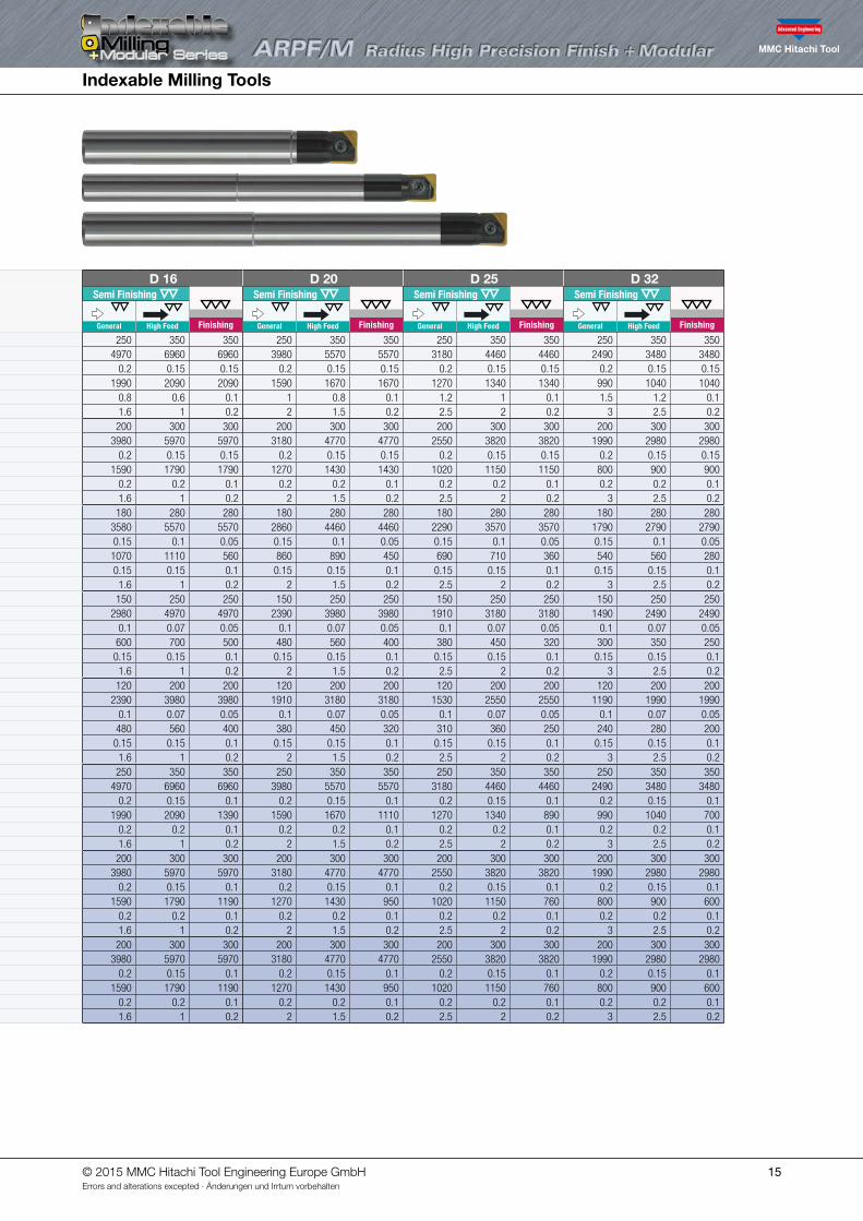
D 8 D 10 D 12 D 16 D 20 D 25 D 32Semi Finishing
Finishing
Semi Finishing
Finishing
Semi Finishing
Finishing
Semi Finishing
Finishing
Semi Finishing
Finishing
Semi Finishing
Finishing
Semi Finishing
Finishing30 40 50
General High Feed General High Feed General High Feed General High Feed General High Feed General High Feed General High Feed
III
Carbon-SteelAlloy-Steel<30HRC
PCA12M • • • Vc m/min 250 350 350 250 350 350 250 350 350 250 350 350 250 350 350 250 350 350 250 350 350n min-1 9950 13930 13930 7960 11140 11140 6630 9280 9280 4970 6960 6960 3980 5570 5570 3180 4460 4460 2490 3480 3480fz mm/t 0.2 0.15 0.1 0.2 0.15 0.15 0.2 0.15 0.15 0.2 0.15 0.15 0.2 0.15 0.15 0.2 0.15 0.15 0.2 0.15 0.15Vf mm/min 3980 4180 2790 3180 3340 3340 2650 2790 2790 1990 2090 2090 1590 1670 1670 1270 1340 1340 990 1040 1040ap mm 0.2 0.15 0.1 0.5 0.3 0.1 0.6 0.4 0.1 0.8 0.6 0.1 1 0.8 0.1 1.2 1 0.1 1.5 1.2 0.1ae mm 0.8 0.4 0.2 1 0.5 0.2 1.2 0.6 0.2 1.6 1 0.2 2 1.5 0.2 2.5 2 0.2 3 2.5 0.2
IIIAlloy-SteelTool-Steel30~40HRC
PCA12M • • • Vc m/min 200 300 300 200 300 300 200 300 300 200 300 300 200 300 300 200 300 300 200 300 300n min-1 7960 11940 11940 6370 9550 9550 5310 7960 7960 3980 5970 5970 3180 4770 4770 2550 3820 3820 1990 2980 2980fz mm/t 0.2 0.15 0.1 0.2 0.15 0.15 0.2 0.15 0.15 0.2 0.15 0.15 0.2 0.15 0.15 0.2 0.15 0.15 0.2 0.15 0.15
PTH08M • • • Vf mm/min 3180 3580 2390 2550 2860 2860 2120 2390 2390 1590 1790 1790 1270 1430 1430 1020 1150 1150 800 900 900ap mm 0.2 0.2 0.1 0.2 0.2 0.1 0.2 0.2 0.1 0.2 0.2 0.1 0.2 0.2 0.1 0.2 0.2 0.1 0.2 0.2 0.1ae mm 0.8 0.4 0.2 1 0.5 0.2 1.2 0.6 0.2 1.6 1 0.2 2 1.5 0.2 2.5 2 0.2 3 2.5 0.2
IV
Pre-Hardened SteelTool-Steel40~50HRC
PCA12M • • • Vc m/min 180 280 280 180 280 280 180 280 280 180 280 280 180 280 280 180 280 280 180 280 280n min-1 7160 11140 11140 5730 8910 8910 4770 7430 7430 3580 5570 5570 2860 4460 4460 2290 3570 3570 1790 2790 2790fz mm/t 0.15 0.1 0.05 0.15 0.1 0.05 0.15 0.1 0.05 0.15 0.1 0.05 0.15 0.1 0.05 0.15 0.1 0.05 0.15 0.1 0.05
PTH08M • • • Vf mm/min 2150 2230 1110 1720 1780 890 1430 1490 740 1070 1110 560 860 890 450 690 710 360 540 560 280ap mm 0.15 0.15 0.1 0.15 0.15 0.1 0.15 0.15 0.1 0.15 0.15 0.1 0.15 0.15 0.1 0.15 0.15 0.1 0.15 0.15 0.1ae mm 0.8 0.4 0.2 1 0.5 0.2 1.2 0.6 0.2 1.6 1 0.2 2 1.5 0.2 2.5 2 0.2 3 2.5 0.2
VHardened SteelTool-Steel50~55HRC
Vc m/min 150 250 250 150 250 250 150 250 250 150 250 250 150 250 250 150 250 250 150 250 250n min-1 5970 9950 9950 4770 7960 7960 3980 6630 6630 2980 4970 4970 2390 3980 3980 1910 3180 3180 1490 2490 2490fz mm/t 0.1 0.07 0.05 0.1 0.07 0.05 0.1 0.07 0.05 0.1 0.07 0.05 0.1 0.07 0.05 0.1 0.07 0.05 0.1 0.07 0.05
PTH08M • • • Vf mm/min 1190 1390 990 950 1110 800 800 930 660 600 700 500 480 560 400 380 450 320 300 350 250ap mm 0.15 0.15 0.1 0.15 0.15 0.1 0.15 0.15 0.1 0.15 0.15 0.1 0.15 0.15 0.1 0.15 0.15 0.1 0.15 0.15 0.1ae mm 0.8 0.4 0.2 1 0.5 0.2 1.2 0.6 0.2 1.6 1 0.2 2 1.5 0.2 2.5 2 0.2 3 2.5 0.2
V Hardened Steel> 55HRC
Vc m/min 120 200 200 120 200 200 120 200 200 120 200 200 120 200 200 120 200 200 120 200 200n min-1 4770 7960 7960 3820 6370 6370 3180 5310 5310 2390 3980 3980 1910 3180 3180 1530 2550 2550 1190 1990 1990fz mm/t 0.1 0.07 0.05 0.1 0.07 0.05 0.1 0.07 0.05 0.1 0.07 0.05 0.1 0.07 0.05 0.1 0.07 0.05 0.1 0.07 0.05
PTH08M • • • Vf mm/min 950 1110 800 760 890 640 640 740 530 480 560 400 380 450 320 310 360 250 240 280 200ap mm 0.15 0.15 0.1 0.15 0.15 0.1 0.15 0.15 0.1 0.15 0.15 0.1 0.15 0.15 0.1 0.15 0.15 0.1 0.15 0.15 0.1ae mm 0.8 0.4 0.2 1 0.5 0.2 1.2 0.6 0.2 1.6 1 0.2 2 1.5 0.2 2.5 2 0.2 3 2.5 0.2
VIII
Cast-IronGGEN-JL10**EN-GJL-***
PCA12M • • • Vc m/min 250 350 350 250 350 350 250 350 350 250 350 350 250 350 350 250 350 350 250 350 350n min-1 9950 13930 13930 7960 11140 11140 6630 9280 9280 4970 6960 6960 3980 5570 5570 3180 4460 4460 2490 3480 3480fz mm/t 0.2 0.15 0.1 0.2 0.15 0.1 0.2 0.15 0.1 0.2 0.15 0.1 0.2 0.15 0.1 0.2 0.15 0.1 0.2 0.15 0.1
PTH08M • • • Vf mm/min 3980 4180 2790 3180 3340 2230 2650 2790 1860 1990 2090 1390 1590 1670 1110 1270 1340 890 990 1040 700ap mm 0.2 0.2 0.1 0.2 0.2 0.1 0.2 0.2 0.1 0.2 0.2 0.1 0.2 0.2 0.1 0.2 0.2 0.1 0.2 0.2 0.1ae mm 0.8 0.4 0.2 1 0.5 0.2 1.2 0.6 0.2 1.6 1 0.2 2 1.5 0.2 2.5 2 0.2 3 2.5 0.2
VIII
Cast-IronGGGEN-JS10**EN-GJS-***
PCA12M • • • Vc m/min 200 300 300 200 300 300 200 300 300 200 300 300 200 300 300 200 300 300 200 300 300n min-1 7960 11940 11940 6370 9550 9550 5310 7960 7960 3980 5970 5970 3180 4770 4770 2550 3820 3820 1990 2980 2980fz mm/t 0.2 0.15 0.1 0.2 0.15 0.1 0.2 0.15 0.1 0.2 0.15 0.1 0.2 0.15 0.1 0.2 0.15 0.1 0.2 0.15 0.1
PTH08M • • • Vf mm/min 3180 3580 2390 2550 2860 1910 2120 2390 1590 1590 1790 1190 1270 1430 950 1020 1150 760 800 900 600ap mm 0.2 0.2 0.1 0.2 0.2 0.1 0.2 0.2 0.1 0.2 0.2 0.1 0.2 0.2 0.1 0.2 0.2 0.1 0.2 0.2 0.1ae mm 0.8 0.4 0.2 1 0.5 0.2 1.2 0.6 0.2 1.6 1 0.2 2 1.5 0.2 2.5 2 0.2 3 2.5 0.2
VI Stainless SteelsHigh alloy Steels
PCA12M • • • Vc m/min 200 300 300 200 300 300 200 300 300 200 300 300 200 300 300 200 300 300 200 300 300n min-1 7960 11940 11940 6370 9550 9550 5310 7960 7960 3980 5970 5970 3180 4770 4770 2550 3820 3820 1990 2980 2980fz mm/t 0.2 0.15 0.1 0.2 0.15 0.1 0.2 0.15 0.1 0.2 0.15 0.1 0.2 0.15 0.1 0.2 0.15 0.1 0.2 0.15 0.1
PTH08M • • • Vf mm/min 3180 3580 2390 2550 2860 1910 2120 2390 1590 1590 1790 1190 1270 1430 950 1020 1150 760 800 900 600ap mm 0.2 0.2 0.1 0.2 0.2 0.1 0.2 0.2 0.1 0.2 0.2 0.1 0.2 0.2 0.1 0.2 0.2 0.1 0.2 0.2 0.1ae mm 0.8 0.4 0.2 1 0.5 0.2 1.2 0.6 0.2 1.6 1 0.2 2 1.5 0.2 2.5 2 0.2 3 2.5 0.2
© 2015 MMC Hitachi Tool Engineering Europe GmbHErrors and alterations excepted · Änderungen und Irrtum vorbehalten
Indexable Milling Tools
15
Work piece material
Recommend grade & Target hardness (HRC)
Emul
sion
Mis
tAi
r
Para meter
D 8 D 10 D 12 D 16 D 20 D 25 D 32Semi Finishing
Finishing
Semi Finishing
Finishing
Semi Finishing
Finishing
Semi Finishing
Finishing
Semi Finishing
Finishing
Semi Finishing
Finishing
Semi Finishing
Finishing30 40 50
General High Feed General High Feed General High Feed General High Feed General High Feed General High Feed General High Feed
III
Carbon-SteelAlloy-Steel<30HRC
PCA12M • • • Vc m/min 250 350 350 250 350 350 250 350 350 250 350 350 250 350 350 250 350 350 250 350 350n min-1 9950 13930 13930 7960 11140 11140 6630 9280 9280 4970 6960 6960 3980 5570 5570 3180 4460 4460 2490 3480 3480fz mm/t 0.2 0.15 0.1 0.2 0.15 0.15 0.2 0.15 0.15 0.2 0.15 0.15 0.2 0.15 0.15 0.2 0.15 0.15 0.2 0.15 0.15Vf mm/min 3980 4180 2790 3180 3340 3340 2650 2790 2790 1990 2090 2090 1590 1670 1670 1270 1340 1340 990 1040 1040ap mm 0.2 0.15 0.1 0.5 0.3 0.1 0.6 0.4 0.1 0.8 0.6 0.1 1 0.8 0.1 1.2 1 0.1 1.5 1.2 0.1ae mm 0.8 0.4 0.2 1 0.5 0.2 1.2 0.6 0.2 1.6 1 0.2 2 1.5 0.2 2.5 2 0.2 3 2.5 0.2
IIIAlloy-SteelTool-Steel30~40HRC
PCA12M • • • Vc m/min 200 300 300 200 300 300 200 300 300 200 300 300 200 300 300 200 300 300 200 300 300n min-1 7960 11940 11940 6370 9550 9550 5310 7960 7960 3980 5970 5970 3180 4770 4770 2550 3820 3820 1990 2980 2980fz mm/t 0.2 0.15 0.1 0.2 0.15 0.15 0.2 0.15 0.15 0.2 0.15 0.15 0.2 0.15 0.15 0.2 0.15 0.15 0.2 0.15 0.15
PTH08M • • • Vf mm/min 3180 3580 2390 2550 2860 2860 2120 2390 2390 1590 1790 1790 1270 1430 1430 1020 1150 1150 800 900 900ap mm 0.2 0.2 0.1 0.2 0.2 0.1 0.2 0.2 0.1 0.2 0.2 0.1 0.2 0.2 0.1 0.2 0.2 0.1 0.2 0.2 0.1ae mm 0.8 0.4 0.2 1 0.5 0.2 1.2 0.6 0.2 1.6 1 0.2 2 1.5 0.2 2.5 2 0.2 3 2.5 0.2
IV
Pre-Hardened SteelTool-Steel40~50HRC
PCA12M • • • Vc m/min 180 280 280 180 280 280 180 280 280 180 280 280 180 280 280 180 280 280 180 280 280n min-1 7160 11140 11140 5730 8910 8910 4770 7430 7430 3580 5570 5570 2860 4460 4460 2290 3570 3570 1790 2790 2790fz mm/t 0.15 0.1 0.05 0.15 0.1 0.05 0.15 0.1 0.05 0.15 0.1 0.05 0.15 0.1 0.05 0.15 0.1 0.05 0.15 0.1 0.05
PTH08M • • • Vf mm/min 2150 2230 1110 1720 1780 890 1430 1490 740 1070 1110 560 860 890 450 690 710 360 540 560 280ap mm 0.15 0.15 0.1 0.15 0.15 0.1 0.15 0.15 0.1 0.15 0.15 0.1 0.15 0.15 0.1 0.15 0.15 0.1 0.15 0.15 0.1ae mm 0.8 0.4 0.2 1 0.5 0.2 1.2 0.6 0.2 1.6 1 0.2 2 1.5 0.2 2.5 2 0.2 3 2.5 0.2
VHardened SteelTool-Steel50~55HRC
Vc m/min 150 250 250 150 250 250 150 250 250 150 250 250 150 250 250 150 250 250 150 250 250n min-1 5970 9950 9950 4770 7960 7960 3980 6630 6630 2980 4970 4970 2390 3980 3980 1910 3180 3180 1490 2490 2490fz mm/t 0.1 0.07 0.05 0.1 0.07 0.05 0.1 0.07 0.05 0.1 0.07 0.05 0.1 0.07 0.05 0.1 0.07 0.05 0.1 0.07 0.05
PTH08M • • • Vf mm/min 1190 1390 990 950 1110 800 800 930 660 600 700 500 480 560 400 380 450 320 300 350 250ap mm 0.15 0.15 0.1 0.15 0.15 0.1 0.15 0.15 0.1 0.15 0.15 0.1 0.15 0.15 0.1 0.15 0.15 0.1 0.15 0.15 0.1ae mm 0.8 0.4 0.2 1 0.5 0.2 1.2 0.6 0.2 1.6 1 0.2 2 1.5 0.2 2.5 2 0.2 3 2.5 0.2
V Hardened Steel> 55HRC
Vc m/min 120 200 200 120 200 200 120 200 200 120 200 200 120 200 200 120 200 200 120 200 200n min-1 4770 7960 7960 3820 6370 6370 3180 5310 5310 2390 3980 3980 1910 3180 3180 1530 2550 2550 1190 1990 1990fz mm/t 0.1 0.07 0.05 0.1 0.07 0.05 0.1 0.07 0.05 0.1 0.07 0.05 0.1 0.07 0.05 0.1 0.07 0.05 0.1 0.07 0.05
PTH08M • • • Vf mm/min 950 1110 800 760 890 640 640 740 530 480 560 400 380 450 320 310 360 250 240 280 200ap mm 0.15 0.15 0.1 0.15 0.15 0.1 0.15 0.15 0.1 0.15 0.15 0.1 0.15 0.15 0.1 0.15 0.15 0.1 0.15 0.15 0.1ae mm 0.8 0.4 0.2 1 0.5 0.2 1.2 0.6 0.2 1.6 1 0.2 2 1.5 0.2 2.5 2 0.2 3 2.5 0.2
VIII
Cast-IronGGEN-JL10**EN-GJL-***
PCA12M • • • Vc m/min 250 350 350 250 350 350 250 350 350 250 350 350 250 350 350 250 350 350 250 350 350n min-1 9950 13930 13930 7960 11140 11140 6630 9280 9280 4970 6960 6960 3980 5570 5570 3180 4460 4460 2490 3480 3480fz mm/t 0.2 0.15 0.1 0.2 0.15 0.1 0.2 0.15 0.1 0.2 0.15 0.1 0.2 0.15 0.1 0.2 0.15 0.1 0.2 0.15 0.1
PTH08M • • • Vf mm/min 3980 4180 2790 3180 3340 2230 2650 2790 1860 1990 2090 1390 1590 1670 1110 1270 1340 890 990 1040 700ap mm 0.2 0.2 0.1 0.2 0.2 0.1 0.2 0.2 0.1 0.2 0.2 0.1 0.2 0.2 0.1 0.2 0.2 0.1 0.2 0.2 0.1ae mm 0.8 0.4 0.2 1 0.5 0.2 1.2 0.6 0.2 1.6 1 0.2 2 1.5 0.2 2.5 2 0.2 3 2.5 0.2
VIII
Cast-IronGGGEN-JS10**EN-GJS-***
PCA12M • • • Vc m/min 200 300 300 200 300 300 200 300 300 200 300 300 200 300 300 200 300 300 200 300 300n min-1 7960 11940 11940 6370 9550 9550 5310 7960 7960 3980 5970 5970 3180 4770 4770 2550 3820 3820 1990 2980 2980fz mm/t 0.2 0.15 0.1 0.2 0.15 0.1 0.2 0.15 0.1 0.2 0.15 0.1 0.2 0.15 0.1 0.2 0.15 0.1 0.2 0.15 0.1
PTH08M • • • Vf mm/min 3180 3580 2390 2550 2860 1910 2120 2390 1590 1590 1790 1190 1270 1430 950 1020 1150 760 800 900 600ap mm 0.2 0.2 0.1 0.2 0.2 0.1 0.2 0.2 0.1 0.2 0.2 0.1 0.2 0.2 0.1 0.2 0.2 0.1 0.2 0.2 0.1ae mm 0.8 0.4 0.2 1 0.5 0.2 1.2 0.6 0.2 1.6 1 0.2 2 1.5 0.2 2.5 2 0.2 3 2.5 0.2
VI Stainless SteelsHigh alloy Steels
PCA12M • • • Vc m/min 200 300 300 200 300 300 200 300 300 200 300 300 200 300 300 200 300 300 200 300 300n min-1 7960 11940 11940 6370 9550 9550 5310 7960 7960 3980 5970 5970 3180 4770 4770 2550 3820 3820 1990 2980 2980fz mm/t 0.2 0.15 0.1 0.2 0.15 0.1 0.2 0.15 0.1 0.2 0.15 0.1 0.2 0.15 0.1 0.2 0.15 0.1 0.2 0.15 0.1
PTH08M • • • Vf mm/min 3180 3580 2390 2550 2860 1910 2120 2390 1590 1590 1790 1190 1270 1430 950 1020 1150 760 800 900 600ap mm 0.2 0.2 0.1 0.2 0.2 0.1 0.2 0.2 0.1 0.2 0.2 0.1 0.2 0.2 0.1 0.2 0.2 0.1 0.2 0.2 0.1ae mm 0.8 0.4 0.2 1 0.5 0.2 1.2 0.6 0.2 1.6 1 0.2 2 1.5 0.2 2.5 2 0.2 3 2.5 0.2
© 2015 MMC Hitachi Tool Engineering Europe GmbHErrors and alterations excepted · Änderungen und Irrtum vorbehalten
Indexable Milling Tools
16
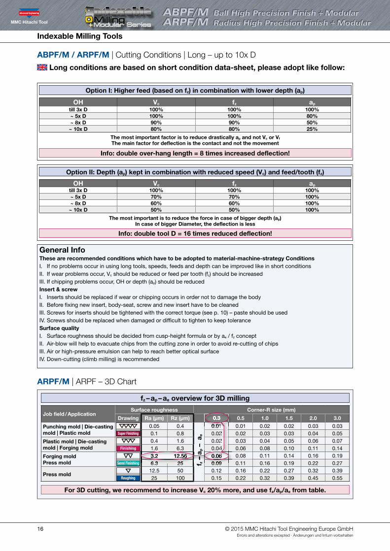
ABPF/M / ARPF/M | Cutting Conditions | Long – up to 10x D
ARPF/M | ARPF – 3D Chart
fz – ap – ae overview for 3D milling
Option I: Higher feed (based on fz) in combination with lower depth (ap)
Long conditions are based on short condition data-sheet, please adopt like follow:
Job field / ApplicationSurface roughness Corner-R size (mm)
Drawing Ra (µm) Rz (µm) 0.3 0.5 1.0 1.5 2.0 3.0
Punching mold | Die-casting mold | Plastic mold Super Finishing
0.05 0.4
fz –
ap –
ae
0.01 0.01 0.02 0.02 0.03 0.03 0.1 0.8 0.02 0.02 0.03 0.03 0.04 0.05
Plastic mold | Die-casting mold | Forging mold Finishing
0.4 1.6 0.02 0.03 0.04 0.05 0.06 0.07 1.6 6.3 0.04 0.06 0.08 0.10 0.11 0.14
Forging moldPress mold Semi Finishing
3.2 12.56 0.06 0.08 0.11 0.14 0.16 0.19 6.3 25 0.09 0.11 0.16 0.19 0.22 0.27
Press moldRoughing
12.5 50 0.12 0.16 0.22 0.27 0.32 0.39 25 100 0.15 0.22 0.32 0.39 0.45 0.55
OH Vc fz ap
till 3x D 100% 100% 100%~ 5x D 100% 100% 80%~ 8x D 90% 90% 50%~ 10x D 80% 80% 25%
The most important factor is to reduce drastically ap and not Vc or Vf The main factor for deflection is the contact and not the movement
Info: double over-hang length = 8 times increased deflection!
Option II: Depth (ap) kept in combination with reduced speed (Vc) and feed/tooth (fz)
OH Vc fz ap
till 3x D 100% 100% 100%~ 5x D 70% 70% 100%~ 8x D 60% 60% 100%~ 10x D 50% 50% 100%
The most important is to reduce the force in case of bigger depth (ap)In case of bigger Diameter, the deflection is less
Info: double tool D = 16 times reduced deflection!
For 3D cutting, we recommend to increase Vc 20% more, and use fz/ap/ae from table.
0.01 0.02 0.02 0.04
– a
– a
General Info These are recommended conditions which have to be adopted to material-machine-strategy ConditionsI. If no problems occur in using long tools, speeds, feeds and depth can be improved like in short conditionsII. If wear problems occur, Vc should be reduced or feed per tooth (fz) should be increasedIII. If chipping problems occur, OH or depth (ap) should be reducedInsert & screwI. Inserts should be replaced if wear or chipping occurs in order not to damage the bodyII. Before fixing new insert, body-seat, screw and new insert have to be cleanedIII. Screws for inserts should be tightened with the correct torque (see p. 10) – paste should be used IV. Screws should be replaced when damaged or difficult to tighten to keep toleranceSurface qualityI. Surface roughness should be decided from cusp-height formula or by ae / fz conceptII. Air-blow will help to evacuate chips from the cutting zone in order to avoid re-cutting of chips III. Air or high-pressure emulsion can help to reach better optical surfaceIV. Down-cutting (climb milling) is recommended
6.3 253.2 12.56
0.09 0.06 0.06
0.01 0.01
0.3
© 2015 MMC Hitachi Tool Engineering Europe GmbHErrors and alterations excepted · Änderungen und Irrtum vorbehalten
Indexable Milling Tools
17
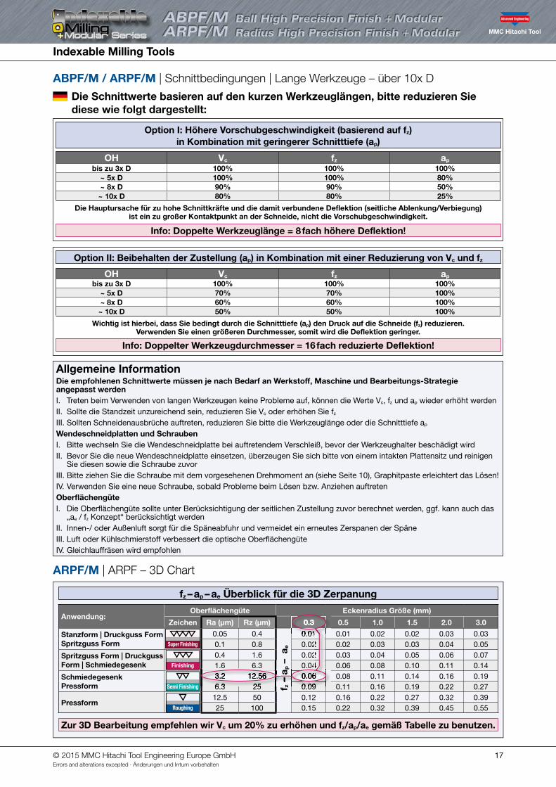
ABPF/M / ARPF/M | Schnittbedingungen | Lange Werkzeuge – über 10x D
ARPF/M | ARPF – 3D Chart
fz – ap – ae Überblick für die 3D Zerpanung
Die Schnittwerte basieren auf den kurzen Werkzeuglängen, bitte reduzieren Sie diese wie folgt dargestellt:
Anwendung:Oberflächengüte Eckenradius Größe (mm)
Zeichen Ra (µm) Rz (µm) 0.3 0.5 1.0 1.5 2.0 3.0
Stanzform | Druckguss Form Spritzguss Form Super Finishing
0.05 0.4
fz –
ap –
ae
0.01 0.01 0.02 0.02 0.03 0.03 0.1 0.8 0.02 0.02 0.03 0.03 0.04 0.05
Spritzguss Form | Druckguss Form | Schmiedegesenk Finishing
0.4 1.6 0.02 0.03 0.04 0.05 0.06 0.07 1.6 6.3 0.04 0.06 0.08 0.10 0.11 0.14
Schmiedegesenk Pressform Semi Finishing
3.2 12.56 0.06 0.08 0.11 0.14 0.16 0.19 6.3 25 0.09 0.11 0.16 0.19 0.22 0.27
PressformRoughing
12.5 50 0.12 0.16 0.22 0.27 0.32 0.39 25 100 0.15 0.22 0.32 0.39 0.45 0.55
OH Vc fz ap
bis zu 3x D 100% 100% 100%~ 5x D 100% 100% 80%~ 8x D 90% 90% 50%~ 10x D 80% 80% 25%
Die Hauptursache für zu hohe Schnittkräfte und die damit verbundene Deflektion (seitliche Ablenkung/Verbiegung) ist ein zu großer Kontaktpunkt an der Schneide, nicht die Vorschubgeschwindigkeit.
Info: Doppelte Werkzeuglänge = 8 fach höhere Deflektion!
Option II: Beibehalten der Zustellung (ap) in Kombination mit einer Reduzierung von Vc und fz
OH Vc fz ap
bis zu 3x D 100% 100% 100%~ 5x D 70% 70% 100%~ 8x D 60% 60% 100%~ 10x D 50% 50% 100%
Wichtig ist hierbei, dass Sie bedingt durch die Schnitttiefe (ap) den Druck auf die Schneide (fz) reduzieren.Verwenden Sie einen größeren Durchmesser, somit wird die Deflektion geringer.
Info: Doppelter Werkzeugdurchmesser = 16 fach reduzierte Deflektion!
Zur 3D Bearbeitung empfehlen wir Vc um 20% zu erhöhen und fz/ap/ae gemäß Tabelle zu benutzen.
0.01 0.02 0.02 0.04
– a
Allgemeine Information Die empfohlenen Schnittwerte müssen je nach Bedarf an Werkstoff, Maschine und Bearbeitungs-Strategie angepasst werdenI. Treten beim Verwenden von langen Werkzeugen keine Probleme auf, können die Werte Vc, fz und ap wieder erhöht werdenII. Sollte die Standzeit unzureichend sein, reduzieren Sie Vc oder erhöhen Sie fz
III. Sollten Schneidenausbrüche auftreten, reduzieren Sie bitte die Werkzeuglänge oder die Schnitttiefe ap
Wendeschneidplatten und SchraubenI. Bitte wechseln Sie die Wendeschneidplatte bei auftretendem Verschleiß, bevor der Werkzeughalter beschädigt wirdII. Bevor Sie die neue Wendeschneidplatte einsetzen, überzeugen Sie sich bitte von einem intakten Plattensitz und reinigen
Sie diesen sowie die Schraube zuvorIII. Bitte ziehen Sie die Schraube mit dem vorgesehenen Drehmoment an (siehe Seite 10), Graphitpaste erleichtert das Lösen!IV. Verwenden Sie eine neue Schraube, sobald Probleme beim Lösen bzw. Anziehen auftretenOberflächengüteI. Die Oberflächengüte sollte unter Berücksichtigung der seitlichen Zustellung zuvor berechnet werden, ggf. kann auch das
„ae / fz Konzept“ berücksichtigt werdenII. Innen-/ oder Außenluft sorgt für die Späneabfuhr und vermeidet ein erneutes Zerspanen der SpäneIII. Luft oder Kühlschmierstoff verbessert die optische OberflächengüteIV. Gleichlauffräsen wird empfohlen
6.3 253.2 12.56
0.09 0.06 0.06
0.01 0.01
0.3
Option I: Höhere Vorschubgeschwindigkeit (basierend auf fz) in Kombination mit geringerer Schnitttiefe (ap)
© 2015 MMC Hitachi Tool Engineering Europe GmbHErrors and alterations excepted · Änderungen und Irrtum vorbehalten
Indexable Milling Tools
18
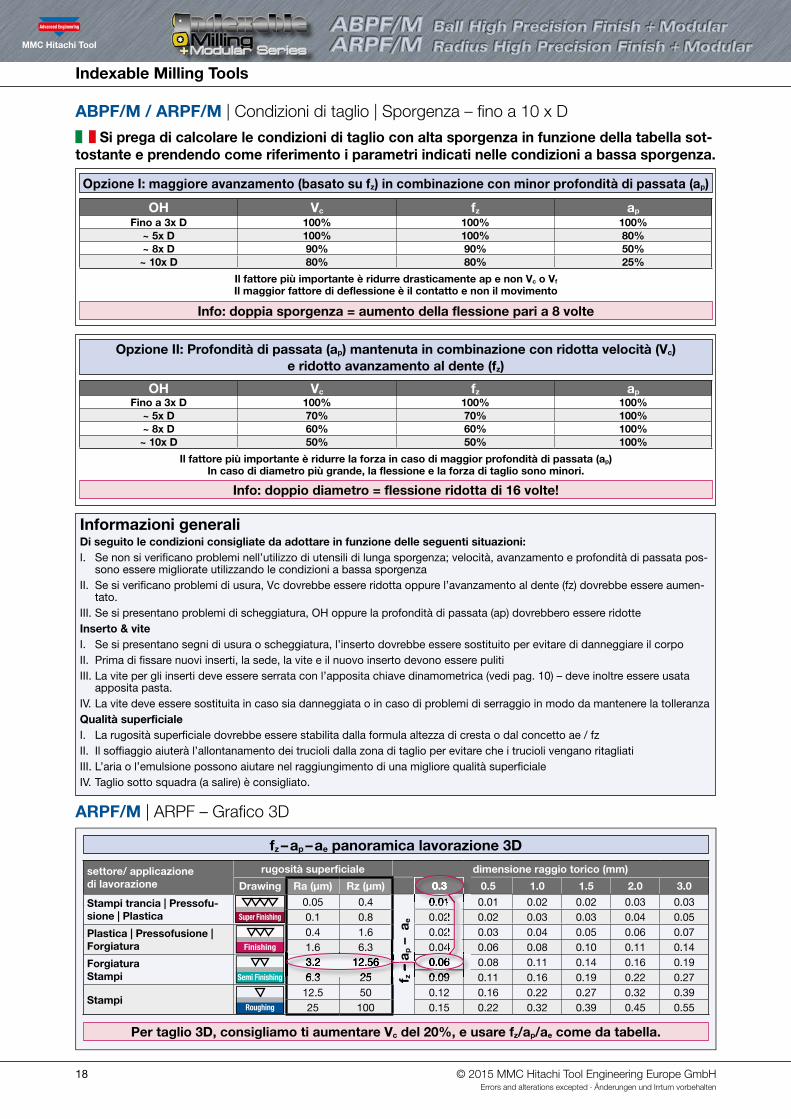
ABPF/M / ARPF/M | Condizioni di taglio | Sporgenza – fino a 10 x D
Si prega di calcolare le condizioni di taglio con alta sporgenza in funzione della tabella sot-tostante e prendendo come riferimento i parametri indicati nelle condizioni a bassa sporgenza.
ARPF/M | ARPF – Grafico 3D
fz – ap – ae panoramica lavorazione 3D
Opzione I: maggiore avanzamento (basato su fz) in combinazione con minor profondità di passata (ap)
settore/ applicazione di lavorazione
rugosità superficiale dimensione raggio torico (mm)
Drawing Ra (µm) Rz (µm) 0.3 0.5 1.0 1.5 2.0 3.0
Stampi trancia | Pressofu-sione | Plastica Super Finishing
0.05 0.4
fz –
ap –
ae
0.01 0.01 0.02 0.02 0.03 0.03 0.1 0.8 0.02 0.02 0.03 0.03 0.04 0.05
Plastica | Pressofusione | Forgiatura Finishing
0.4 1.6 0.02 0.03 0.04 0.05 0.06 0.07 1.6 6.3 0.04 0.06 0.08 0.10 0.11 0.14
ForgiaturaStampi Semi Finishing
3.2 12.56 0.06 0.08 0.11 0.14 0.16 0.19 6.3 25 0.09 0.11 0.16 0.19 0.22 0.27
StampiRoughing
12.5 50 0.12 0.16 0.22 0.27 0.32 0.39 25 100 0.15 0.22 0.32 0.39 0.45 0.55
OH Vc fz ap
Fino a 3x D 100% 100% 100%~ 5x D 100% 100% 80%~ 8x D 90% 90% 50%~ 10x D 80% 80% 25%
Il fattore più importante è ridurre drasticamente ap e non Vc o Vf
Il maggior fattore di deflessione è il contatto e non il movimento
Info: doppia sporgenza = aumento della flessione pari a 8 volte
Opzione II: Profondità di passata (ap) mantenuta in combinazione con ridotta velocità (Vc) e ridotto avanzamento al dente (fz)
OH Vc fz ap
Fino a 3x D 100% 100% 100%~ 5x D 70% 70% 100%~ 8x D 60% 60% 100%~ 10x D 50% 50% 100%
Il fattore più importante è ridurre la forza in caso di maggior profondità di passata (ap)In caso di diametro più grande, la flessione e la forza di taglio sono minori.
Info: doppio diametro = flessione ridotta di 16 volte!
Per taglio 3D, consigliamo ti aumentare Vc del 20%, e usare fz/ap/ae come da tabella.
0.01 0.02 0.02 0.04
– a
– a
Informazioni generali Di seguito le condizioni consigliate da adottare in funzione delle seguenti situazioni:I. Se non si verificano problemi nell’utilizzo di utensili di lunga sporgenza; velocità, avanzamento e profondità di passata pos-
sono essere migliorate utilizzando le condizioni a bassa sporgenzaII. Se si verificano problemi di usura, Vc dovrebbe essere ridotta oppure l’avanzamento al dente (fz) dovrebbe essere aumen-
tato.III. Se si presentano problemi di scheggiatura, OH oppure la profondità di passata (ap) dovrebbero essere ridotteInserto & viteI. Se si presentano segni di usura o scheggiatura, l’inserto dovrebbe essere sostituito per evitare di danneggiare il corpoII. Prima di fissare nuovi inserti, la sede, la vite e il nuovo inserto devono essere pulitiIII. La vite per gli inserti deve essere serrata con l’apposita chiave dinamometrica (vedi pag. 10) – deve inoltre essere usata
apposita pasta.IV. La vite deve essere sostituita in caso sia danneggiata o in caso di problemi di serraggio in modo da mantenere la tolleranzaQualità superficialeI. La rugosità superficiale dovrebbe essere stabilita dalla formula altezza di cresta o dal concetto ae / fzII. Il soffiaggio aiuterà l’allontanamento dei trucioli dalla zona di taglio per evitare che i trucioli vengano ritagliatiIII. L’aria o l’emulsione possono aiutare nel raggiungimento di una migliore qualità superficiale IV. Taglio sotto squadra (a salire) è consigliato.
6.3 253.2 12.56
0.09 0.06 0.06
0.01 0.01
0.3
© 2015 MMC Hitachi Tool Engineering Europe GmbHErrors and alterations excepted · Änderungen und Irrtum vorbehalten

Indexable Milling Tools
19
ABPF/M / ARPF/M | Condiciones de corte | Longitud hasta 10 x D
Las condiciones con gran voladizo están basadas en la hoja de datos con poco voladizo, por favor adaptar de la siguiente manera:
ARPF/M | ARPF – Tabla 3D
fz – ap – ae Visión general para mecanizado 3D
Opción I: Aumentar el avance (aumentando la fz) en combinación con una profundidad menor (ap)
Campo de trabajo / Aplicación
Rugosidad superficial Corner-R size (mm)
Drawing Ra (µm) Rz (µm) 0.3 0.5 1.0 1.5 2.0 3.0
Punching mold | Die-casting mold | Plastic mold Super Finishing
0.05 0.4
fz –
ap –
ae
0.01 0.01 0.02 0.02 0.03 0.03 0.1 0.8 0.02 0.02 0.03 0.03 0.04 0.05
Plastic mold | Die-casting mold | Forging mold Finishing
0.4 1.6 0.02 0.03 0.04 0.05 0.06 0.07 1.6 6.3 0.04 0.06 0.08 0.10 0.11 0.14
Forging moldPress mold Semi Finishing
3.2 12.56 0.06 0.08 0.11 0.14 0.16 0.19 6.3 25 0.09 0.11 0.16 0.19 0.22 0.27
Press moldRoughing
12.5 50 0.12 0.16 0.22 0.27 0.32 0.39 25 100 0.15 0.22 0.32 0.39 0.45 0.55
OH Vc fz ap
hasta 3x D 100% 100% 100%~ 5x D 100% 100% 80%~ 8x D 90% 90% 50%~ 10x D 80% 80% 25%
El factor más importante es reducir drásticamente ap y no Vc o Vf El principal factor para la flexión de la herramienta es el contacto y no el movimiento
Información: el doble de longitud de voladizo = incremento de 8 veces la flexión de la herramienta!
OH Vc fz ap
hasta 3x D 100% 100% 100%~ 5x D 70% 70% 100%~ 8x D 60% 60% 100%~ 10x D 50% 50% 100%
Lo más importante es reducir el esfuerzo en el caso de grandes profundidades de pasada (ap)En el caso de grandes diámetros, la flexión de la herramienta y el esfuerzo de corte es menor.
Información: el doble de D de la herramienta = reducción de 16 veces la flexión de la herramienta
Para el mecanizado 3D, recomendamos incrementar la Vc un 20% más, y usar la fz/ap/ae de la tabla.
0.01 0.02 0.02 0.04
– a
Información general Estas son las condiciones recomendadas las cuales tienen que ser adaptadas dependiendo de las condiciones de material-máquina-estrategiaI. Si no se producen problemas en el uso de herramientas largas, la velocidad, el avance y la profundidad de pasada se
pueden mejorar al igual que en voladizos cortosII. Si se produce desgaste, la Vc debería reducirse o el avance por diente (fz) debería aumentarseIII. Si se produce micro-roturas, el OH o la profundidad (ap) debería reducirsePlaca y tornilloI. La placa debe cambiarse si se produce desgaste o rotura, con el fin de no dañar el plato.II. Antes de poner la nueva placa, el asiento de la placa, el tornillo y la placa tienen que ser limpiados.III. Los tornillos de las placas deben apretarse con el par correcto (ver p. 10). Además debe usarse pasta.IV. Los tornillos deben ser reemplazados cuando esté dañado para mantener la tolerancia. Calidad superficialI. La rugosidad superficial deber ser decidida con la fórmula para crestas o por el concepto de ae / fz
II. El aire soplado ayudará a evacuar la viruta de la zona de mecanizado con el fin de evitar el remecanizado de viruta III. El aire o la emulsión a alta presión puede ayudar a conseguir una mejor superficie óptica. IV. Se recomienda el mecanizado en concordancia (a derechas)
6.3 253.2 12.56
0.09 0.06 0.06
0.01 0.01
0.3
Opción II: Mantener la profundidad (ap) reduciendo la velocidad de corte (Vc) y el avance por diente (fz)
© 2015 MMC Hitachi Tool Engineering Europe GmbHErrors and alterations excepted · Änderungen und Irrtum vorbehalten
Indexable Milling Tools
20
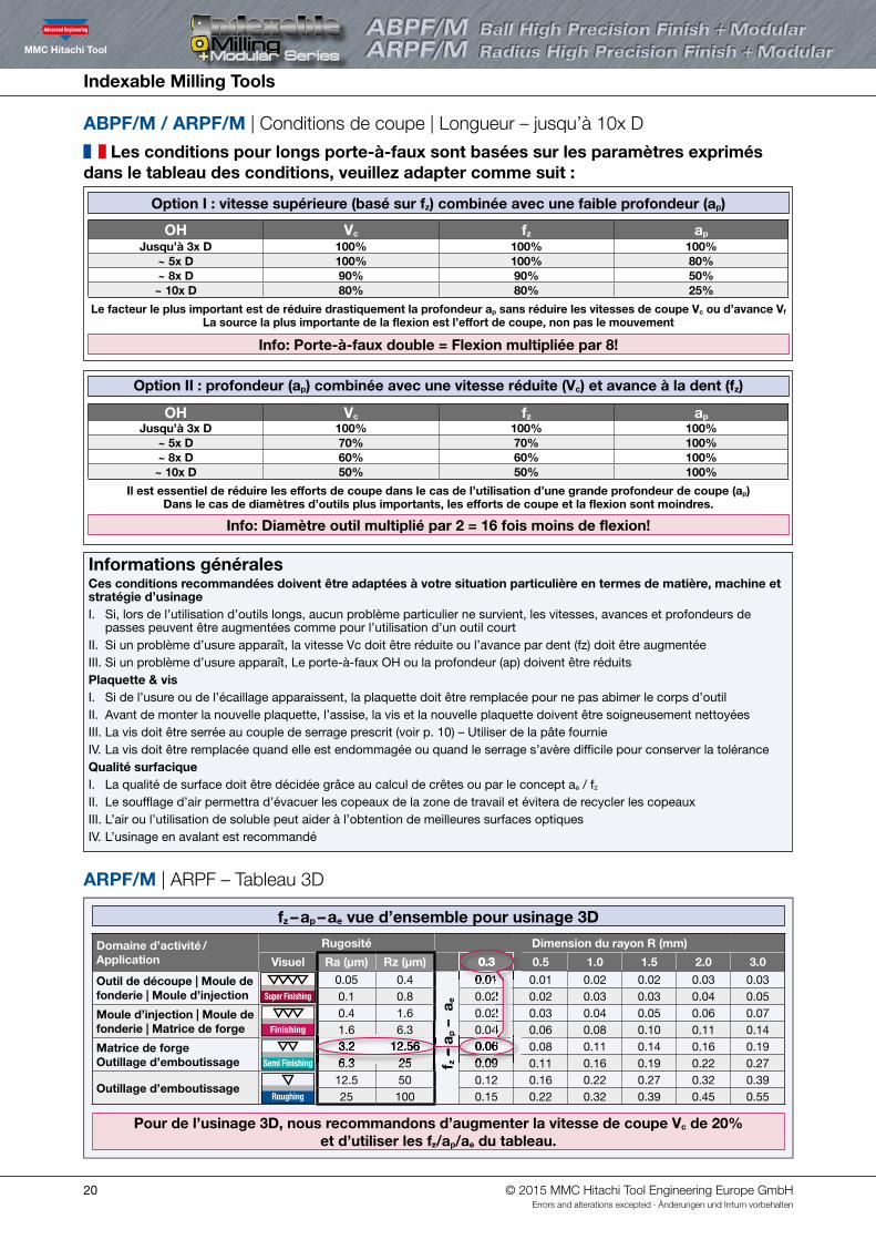
ABPF/M / ARPF/M | Conditions de coupe | Longueur – jusqu’à 10x D
Les conditions pour longs porte-à-faux sont basées sur les paramètres exprimés dans le tableau des conditions, veuillez adapter comme suit :
ARPF/M | ARPF – Tableau 3D
fz – ap – ae vue d’ensemble pour usinage 3D
Option I : vitesse supérieure (basé sur fz) combinée avec une faible profondeur (ap)
Domaine d’activité / Application
Rugosité Dimension du rayon R (mm)
Visuel Ra (µm) Rz (µm) 0.3 0.5 1.0 1.5 2.0 3.0
Outil de découpe | Moule de fonderie | Moule d’injection Super Finishing
0.05 0.4
fz –
ap –
ae
0.01 0.01 0.02 0.02 0.03 0.03 0.1 0.8 0.02 0.02 0.03 0.03 0.04 0.05
Moule d’injection | Moule de fonderie | Matrice de forge Finishing
0.4 1.6 0.02 0.03 0.04 0.05 0.06 0.07 1.6 6.3 0.04 0.06 0.08 0.10 0.11 0.14
Matrice de forgeOutillage d’emboutissage Semi Finishing
3.2 12.56 0.06 0.08 0.11 0.14 0.16 0.19 6.3 25 0.09 0.11 0.16 0.19 0.22 0.27
Outillage d’emboutissageRoughing
12.5 50 0.12 0.16 0.22 0.27 0.32 0.39 25 100 0.15 0.22 0.32 0.39 0.45 0.55
OH Vc fz ap
Jusqu’à 3x D 100% 100% 100%~ 5x D 100% 100% 80%~ 8x D 90% 90% 50%~ 10x D 80% 80% 25%
Le facteur le plus important est de réduire drastiquement la profondeur ap sans réduire les vitesses de coupe Vc ou d’avance Vf La source la plus importante de la flexion est l’effort de coupe, non pas le mouvement
Info: Porte-à-faux double = Flexion multipliée par 8!
OH Vc fz ap
Jusqu’à 3x D 100% 100% 100%~ 5x D 70% 70% 100%~ 8x D 60% 60% 100%~ 10x D 50% 50% 100%
Il est essentiel de réduire les efforts de coupe dans le cas de l’utilisation d’une grande profondeur de coupe (ap)Dans le cas de diamètres d’outils plus importants, les efforts de coupe et la flexion sont moindres.
Info: Diamètre outil multiplié par 2 = 16 fois moins de flexion!
Pour de l’usinage 3D, nous recommandons d’augmenter la vitesse de coupe Vc de 20% et d’utiliser les fz/ap/ae du tableau.
0.01 0.02 0.02 0.04
– a
– a
Informations générales Ces conditions recommandées doivent être adaptées à votre situation particulière en termes de matière, machine et stratégie d’usinageI. Si, lors de l’utilisation d’outils longs, aucun problème particulier ne survient, les vitesses, avances et profondeurs de
passes peuvent être augmentées comme pour l’utilisation d’un outil courtII. Si un problème d’usure apparaît, la vitesse Vc doit être réduite ou l’avance par dent (fz) doit être augmentéeIII. Si un problème d’usure apparaît, Le porte-à-faux OH ou la profondeur (ap) doivent être réduitsPlaquette & visI. Si de l’usure ou de l’écaillage apparaissent, la plaquette doit être remplacée pour ne pas abimer le corps d’outil II. Avant de monter la nouvelle plaquette, l’assise, la vis et la nouvelle plaquette doivent être soigneusement nettoyéesIII. La vis doit être serrée au couple de serrage prescrit (voir p. 10) – Utiliser de la pâte fournieIV. La vis doit être remplacée quand elle est endommagée ou quand le serrage s’avère difficile pour conserver la tolérance Qualité surfacique I. La qualité de surface doit être décidée grâce au calcul de crêtes ou par le concept ae / fz II. Le soufflage d’air permettra d’évacuer les copeaux de la zone de travail et évitera de recycler les copeauxIII. L’air ou l’utilisation de soluble peut aider à l’obtention de meilleures surfaces optiques IV. L’usinage en avalant est recommandé
6.3 253.2 12.56
0.09 0.06 0.06
0.01 0.01
0.3
Option II : profondeur (ap) combinée avec une vitesse réduite (Vc) et avance à la dent (fz)
© 2015 MMC Hitachi Tool Engineering Europe GmbHErrors and alterations excepted · Änderungen und Irrtum vorbehalten
Indexable Milling Tools
21
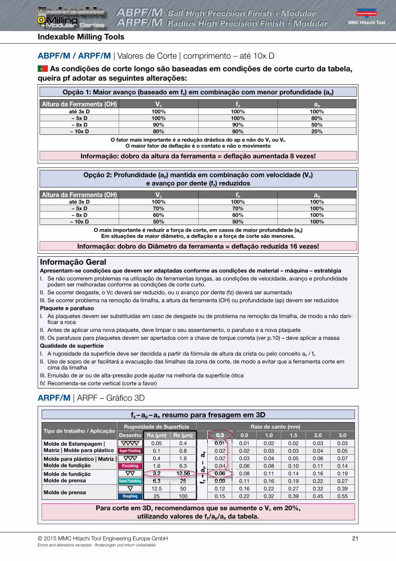
ABPF/M / ARPF/M | Valores de Corte | comprimento – até 10x D
As condições de corte longo são baseadas em condições de corte curto da tabela, queira pf adotar as seguintes alterações:
ARPF/M | ARPF – Gráfico 3D
fz – ap – ae resumo para fresagem em 3D
Opção 1: Maior avanço (baseado em fz) em combinação com menor profundidade (ap)
Altura da Ferramenta (OH) Vc fz ap
até 3x D 100% 100% 100%~ 5x D 100% 100% 80%~ 8x D 90% 90% 50%~ 10x D 80% 80% 25%
O fator mais importante é a redução drástica do ap e não do Vc ou Vf. O maior fator de deflação é o contato e não o movimento
Informação: dobro da altura da ferramenta = deflação aumentada 8 vezes!
Opção 2: Profundidade (ap) mantida em combinação com velocidade (Vc) e avanço por dente (fz) reduzidos
Altura da Ferramenta (OH) Vc fz ap
até 3x D 100% 100% 100%~ 5x D 70% 70% 100%~ 8x D 60% 60% 100%~ 10x D 50% 50% 100%
O mais importante é reduzir a força de corte, em casos de maior profundidade (ap) Em situações de maior diâmetro, a deflação e a força de corte são menores.
Informação: dobro do Diâmetro da ferramenta = deflação reduzida 16 vezes!
Para corte em 3D, recomendamos que se aumente o Vc em 20%, utilizando valores de fz/ap/ae da tabela.
Informação Geral Apresentam-se condições que devem ser adaptadas conforme as condições de material – máquina – estratégiaI. Se não ocorrerem problemas na utilização de ferramentas longas, as condições de velocidade, avanço e profundidade
podem ser melhoradas conforme as condições de corte curto.II. Se ocorrer desgaste, o Vc deverá ser reduzido, ou o avanço por dente (fz) deverá ser aumentadoIII. Se ocorrer problema na remoção da limalha, a altura da ferramenta (OH) ou profundidade (ap) devem ser reduzidosPlaquete e parafusoI. As plaquetes devem ser substituídas em caso de desgaste ou de problema na remoção da limalha, de modo a não dani-
ficar a rocaII. Antes de aplicar uma nova plaquete, deve limpar o seu assentamento, o parafuso e a nova plaqueteIII. Os parafusos para plaquetes devem ser apertados com a chave de torque correta (ver p.10) – deve aplicar a massaQualidade de superfícieI. A rugosidade da superfície deve ser decidida a partir da fórmula de altura da crista ou pelo conceito ae / fz
II. Uso de sopro de ar facilitará a evacuação das limalhas da zona de corte, de modo a evitar que a ferramenta corte em cima da limalha
III. Emulsão de ar ou de alta-pressão pode ajudar na melhoria da superfície óticaIV. Recomenda-se corte vertical (corte a favor)
Tipo de trabalho / Aplicação Rugosidade de Superfície Raio de canto (mm)
Desenho Ra (µm) Rz (µm) 0.3 0.5 1.0 1.5 2.0 3.0
Molde de Estampagem | Matriz | Molde para plástico Super Finishing
0.05 0.4
fz –
ap –
ae
0.01 0.01 0.02 0.02 0.03 0.03 0.1 0.8 0.02 0.02 0.03 0.03 0.04 0.05
Molde para plástico | Matriz | Molde de fundição Finishing
0.4 1.6 0.02 0.03 0.04 0.05 0.06 0.07 1.6 6.3 0.04 0.06 0.08 0.10 0.11 0.14
Molde de fundiçãoMolde de prensa Semi Finishing
3.2 12.56 0.06 0.08 0.11 0.14 0.16 0.19 6.3 25 0.09 0.11 0.16 0.19 0.22 0.27
Molde de prensaRoughing
12.5 50 0.12 0.16 0.22 0.27 0.32 0.39 25 100 0.15 0.22 0.32 0.39 0.45 0.55
0.01 0.02 0.02 0.04
– a
6.3 253.2 12.56
0.09 0.06 0.06
0.01 0.01
0.3
© 2015 MMC Hitachi Tool Engineering Europe GmbHErrors and alterations excepted · Änderungen und Irrtum vorbehalten

Indexable Milling Tools
22 © 2015 MMC Hitachi Tool Engineering Europe GmbHErrors and alterations excepted · Änderungen und Irrtum vorbehalten
Indexable Milling Tools
23© 2015 MMC Hitachi Tool Engineering Europe GmbHErrors and alterations excepted · Änderungen und Irrtum vorbehalten
Distributed by:
Product Range
Indexable Milling Tools
WHNSB Drills
Milling Chucks
Solid Carbide End Mills
Product Range
®
Always up to date: Please check our P50 QuickFinder
HTT
659
1512
AxP
F-M
-6.5
BW
-DS
www.mmc-hitachitool-eu.com/quickfi nder
Itterpark 12 · 40724 Hilden · Germany · Phone +49 (0) 21 03 – 24 82-0 · Fax +49 (0) 21 03 – 24 82-30 E-Mail [email protected] · Internet www.mmc-hitachitool-eu.com © 2015 by MMC Hitachi Tool Engineering Europe GmbH · 4th Edition · Printed in Germany


