1 Abstract In this paper, we describe a simulation environment which is used to examine, validate, and predict the performance of mobile wireless network systems. This simulation environment over- comes many of the limitations found with analytical models, experimentation, and other commercial network simulators available on the market today. This paper describes the simula- tion language, Maisie, which is used to analyze the performance bottlenecks of a multimedia wireless network system being devel- oped at UCLA. By modeling the various components and their integration, this simulation environment is able to accurately predict the performance bottlenecks of the UCLA wireless multi- media networking terminal, determine the trade-off point between the various bottlenecks, and provide performance mea- surements which are not possible through experimentation and too complex for analysis. 1. Introduction In order to develop mobile wireless network algorithms that sup- port multimedia communications, the designer is presented with a host of design alternatives. The problems range from having to support different patterns of mobility to integrating the traffic generators, coders and decoders for voice, data, and video traffic, each with differing computational and communication resource requirements in the communication protocol. A few operating system kernels have been designed to support wireless and mobile communication and a number of protocols have been devised to solve the numerous topology setup and maintenance, media access control, and transmission problems in the mobile environment. Commercial radios designed to be hooked up with laptops for wireless multimedia transmissions are available in the market. Thus although solutions to different facets of the wireless mobile information system design are appearing, relatively little effort has been devoted to understand- ing the performance impact of the interactions among different components of the system. Traditionally, analysis, simulation and measurement have all been used to evaluate the performance of network protocols and multimedia systems. Measurement-based approaches are useful only after the system has been deployed. Although they offer the most accurate evaluations of performance problems, they are often inadequate because it may be infeasible to modify the deployed system to experiment with a large range of design parameters. Even when such modifications are feasible, the cost of the necessary software and hardware modifications may be exorbitant. Analytical models offer the opportunity to quickly examine a large parameter space to identify efficient configura- tions; however for complex systems with many interacting com- ponents, analytical models may either be inaccurate or computationally intractable. For complex, heterogenous systems, simulations are often the only realistic alternative to performance prediction. The primary drawback with detailed simulation models is that they are frequently slow. Experience with many existing network simulators has shown that a performance study of wireless proto- cols for even small networks (tens of nodes) can take many days; running such simulations for networks involving a large number of mobile elements is clearly infeasible. Recent experience with parallel execution of models for personal communication sys- tems has shown that parallelism offers significant potential to improve the execution time for these models; it is likely that these techniques can also be exploited to improve the execution time for simulation models of wireless networks. This paper describes such an environment. The rest of the paper is organized as follows: We begin with a description of the primary operating system, net- work, and hardware components of a mobile, wireless multime- dia information system is section 2. Section 3 discusses the use of existing simulation environments to analyze the performance of such systems. Section 4 describes the new simulation environ- ment. The environment is built using an existing simulation lan- guage called Maisie that is also described briefly in this section. Section 5 presents the results of a simulation study to evaluate the performance of a specific mobile, wireless system that is being designed at UCLA. Experiments to validate the simulation are also presented. In section 6 we conclude with ongoing research to evaluate other components of the proposed multimedia wireless network. 2. Mobile Wireless System Implementation In this section we describe the node architecture and the imple- mentation of the network control functions, multimedia support, communication substrates, and the interfaces between these as shown in Figure 1 for the Wireless Adaptive Mobile Information System (WAMIS) research project at UCLA [12]. Applications are needed for interaction between the system and the user. Mul- Mobile Wireless Network System Simulation Joel Short, Rajive Bagrodia, Leonard Kleinrock Computer Science Department University of California, Los Angeles Los Angeles, CA 90024 * This work was supported in part by the Advanced Research Projects Agency, ARPA/CSTO, under Contract J-FBI-93-112 Computer Aided Design of High Performance Wireless Networked Systems.
Transcript
1
AbstractIn this paper, we describe a simulation environment which isused to examine, validate, and predict the performance of mobilewireless network systems. This simulation environment over-comes many of the limitations found with analytical models,experimentation, and other commercial network simulatorsavailable on the market today. This paper describes the simula-tion language, Maisie, which is used to analyze the performancebottlenecks of a multimedia wireless network system being devel-oped at UCLA. By modeling the various components and theirintegration, this simulation environment is able to accuratelypredict the performance bottlenecks of the UCLA wireless multi-media networking terminal, determine the trade-off pointbetween the various bottlenecks, and provide performance mea-surements which are not possible through experimentation andtoo complex for analysis.
1. IntroductionIn order to develop mobile wireless network algorithms that sup-port multimedia communications, the designer is presented witha host of design alternatives. The problems range from having tosupport different patterns of mobility to integrating the trafficgenerators, coders and decoders for voice, data, and video traffic,each with differing computational and communication resourcerequirements in the communication protocol.
A few operating system kernels have been designed to supportwireless and mobile communication and a number of protocolshave been devised to solve the numerous topology setup andmaintenance, media access control, and transmission problems inthe mobile environment. Commercial radios designed to behooked up with laptops for wireless multimedia transmissionsare available in the market. Thus although solutions to differentfacets of the wireless mobile information system design areappearing, relatively little effort has been devoted to understand-ing the performance impact of the interactions among differentcomponents of the system.
Traditionally, analysis, simulation and measurement have allbeen used to evaluate the performance of network protocols andmultimedia systems. Measurement-based approaches are usefulonly after the system has been deployed. Although they offer themost accurate evaluations of performance problems, they areoften inadequate because it may be infeasible to modify thedeployed system to experiment with a large range of design
parameters. Even when such modifications are feasible, the costof the necessary software and hardware modifications may beexorbitant. Analytical models offer the opportunity to quicklyexamine a large parameter space to identify efficient configura-tions; however for complex systems with many interacting com-ponents, analytical models may either be inaccurate orcomputationally intractable. For complex, heterogenous systems,simulations are often the only realistic alternative to performanceprediction.
The primary drawback with detailed simulation models is thatthey are frequently slow. Experience with many existing networksimulators has shown that a performance study of wireless proto-cols for even small networks (tens of nodes) can take many days;running such simulations for networks involving a large numberof mobile elements is clearly infeasible. Recent experience withparallel execution of models for personal communication sys-tems has shown that parallelism offers significant potential toimprove the execution time for these models; it is likely thatthese techniques can also be exploited to improve the executiontime for simulation models of wireless networks. This paperdescribes such an environment.
The rest of the paper is organized as follows:We begin with a description of the primary operating system, net-work, and hardware components of a mobile, wireless multime-dia information system is section 2. Section 3 discusses the use ofexisting simulation environments to analyze the performance ofsuch systems. Section 4 describes the new simulation environ-ment. The environment is built using an existing simulation lan-guage called Maisie that is also described briefly in this section.Section 5 presents the results of a simulation study to evaluate theperformance of a specific mobile, wireless system that is beingdesigned at UCLA. Experiments to validate the simulation arealso presented. In section 6 we conclude with ongoing research toevaluate other components of the proposed multimedia wirelessnetwork.
2. Mobile Wireless System ImplementationIn this section we describe the node architecture and the imple-mentation of the network control functions, multimedia support,communication substrates, and the interfaces between these asshown in Figure 1 for the Wireless Adaptive Mobile InformationSystem (WAMIS) research project at UCLA [12]. Applicationsare needed for interaction between the system and the user. Mul-
Mobile Wireless Network System Simulation
Joel Short, Rajive Bagrodia, Leonard KleinrockComputer Science Department
University of California, Los AngelesLos Angeles, CA 90024
* This work was supported in part by the Advanced Research Projects Agency, ARPA/CSTO, under Contract J-FBI-93-112 Computer Aided Design ofHigh Performance Wireless Networked Systems.
2
timedia support is necessary not only for acquisition and presen-tation of video, speech, and data but also for coding/decoding forefficient transmission through the wireless network. The networkcontrol functions are responsible for control and interfacingbetween the multimedia devices and the communication sub-strate(s).
The networking algorithms, network operating system, andapplications are implemented inside the laptop. The multimediasupport (video and speech) is currently integrated into the systemas ISA cards in a docking station. The docking station also con-tains the Packet Interface (PI) card used for connection to theradio. Technology is enabling the integration of these devicesinto the laptop via the PCMCIA interface. We are starting to seethe emergence of camera and microphones being integrated intolaptops today. Many commercially available radios and othernetwork devices can connect directly to the laptop via a PCM-CIA type interface and not require this additional interfacinghardware.
2.1 Network Control Functions
The network control functions, shown in Figure 1, comprisenumerous software components which can be used to supportself-configuring, multihop, multimedia networking. These com-ponents can be broken down into end-to-end transport control,internetworking and connectivity control, subnetwork control,and finally link and mobility control. In order to provide flexibleimplementation for rapid prototyping and easy modification forexperimentation, these functions are written in C and supportedby the operating system to isolate the architecture and implemen-
Communications Substrate
End-EndTransport Control
Video
Subnetwork Control
Wireless
Application
USER
internet
WirelinePackets
Packets
Adaptive Wireless
SpeechData
Communications Substrate
Link & Mobility Control
WirelessConnection
Internetworking &Connectivity Control
Link Control
Wired
Figure 1: Node Functionality
tation details from the network algorithms. Interfacing is needednot only between the hardware and software, but also betweenthe various network functions. The network control algorithmsand protocols are responsible for making sure the data betweenapplications are transferred via the appropriate communicationchannel as efficiently as possible in support of the desired qualityof service. The integration of the various components fit into thestandard OSI/ISO type model as illustrated in Figure 2.
2.1.1 Applications
The standard set of TCP/IP protocol suite applications supporttext based services like remote login or file transfers. New appli-cations are now appearing which support multimedia (Mosaicand video conferencing applications). In order see the effect anddemonstrate multimedia on this new self configuring, multihop,multimedia network, a video conferencing application was devel-oped. This application (VideoTALK) brings together video,which uses UDP, and data, which uses TCP, into a single applica-tion on the laptop. In order to test the performance of the system,testing tools were developed to measure throughput, delay,packet loss, and track adaptive parameters such as code, power,and spreading factor (i.e. chips/bit). A topology analyzer program(TOPO) was developed which can be used in the simulation envi-ronment or in the implemented system to graphically analyze thevirtual topology of the wireless multihop subnet.
2.1.2 Transport and Internetworking Control
Since internetworking requires compatibility with existing net-works and protocols, the TCP/IP protocol suite has been imple-mented without need for modifications. Since the InternetProtocol can be used in conjunction with various communicationsubstrates, most of the new algorithm development takes placebelow the network layer. The network layer is responsible forsupporting various communication substrates such as internetrouting, segmentation, etc. Above the network layer, the transportprotocols (TCP and UDP) provide the required support for end-to-end reliability, congestion control, etc. These transport proto-
Figure 2: Network Control Functions
Physical
Data Link
Network
Transport
ApplicationMultimedia
Adaptive
Wired
Instant &
Wireless NodeWired Node
Wireless
Wireless
Internet-
Reliable
Reconfig-
working
Sub-Network
Physical
Data Link
Network
Transport
Application
Physical
Data Link
Network
Physical
Data Link
Sub-Network
Physical
Data Link
Physical
Data Link
Sub-Network
Networksurable
Wired/Wireless Node
Wireless NodeMultihop Mode
Gateway Mode
3
cols interact with the applications described in the previous sec-tion by using sockets to buffer the bit stream so packetization cantake place.
Although wireless communication is useful to support mobilecommunication, typically wired connections can support muchhigher bandwidth and are less prone to errors in the wirelessmodems. Therefore, wired connections should be utilized when-ever possible. Wired connections, such as ethernet, can utilizethe standard PCMCIA card for networking. In order to support acombination of wired and wireless communication, providewireless multihop functionality, and support instant infrastruc-ture networking, a node should be able to function in three differ-ent modes (gateway, multihop, or end node) as shown in Figure2. A node functions as a gateway when both wired and wirelessconnections are available. In the gateway mode, it will forwardpackets between the wired and wireless domains as necessary. Inthe multihop mode, it will follow the sub-network routing proto-col to provide wireless multihop communication within the sub-net.
2.1.3 Sub-network Control
The functionalities which support instant and reconfigurable net-works are new and have been added into the TCP/IP stack (Fig-ure 3). Since many of the proposed schemes for supportinginstant and reconfigurable network topologies are based uponTDMA to control channel contention. A clustering algorithm[10] was implemented which is heavily based on TDMA controland synchronization to test the feasibility and overhead of imple-menting this functionality in software.
2.1.4 Link Layer Control
The Data Link layer shown in Figure 2 supports a new functionunique to wireless networking for mobility control. Mobilitycontrol is used for setting appropriate hardware parameters suchas the CDMA code or transmit power level. Measurements suchas Signal to Interference Ratio (SIR) are fed back from the radiointo the link control algorithms to do power control and mini-mize the power consumption of the link, reduce interference, andprovide admission control such as described in [2].
2.2 Operating System
To integrate all these network control components together, anoperating system is desired such as we see in Figure 3. There arenumerous operating systems available today such as MicrosoftWindows, PC-Disk Operating System, and UNIX, but these sys-tems aren’t designed for ease of programmability or flexibilityfor the types of functionality described above. An operating sys-tem is desired which is compatible with existing platforms todaybut still provide functionality such as multi-tasking and packetprocessing capability useful to network control algorithms. Anetwork operating system is able to function on a layer on top ofan existing native operating system and provide the required net-work functionality and services. A public domain network oper-ating system (NOS, also known as KA9Q developed by PhilKarn) designed to support packet radio meets the flexibility
requirements[4]. It runs on top of DOS and includes its own mul-titasking scheduler. The benefit of this multitasking operatingsystem is that each algorithm or protocol necessary to supportthis network can be developed as its own process. The multitask-ing kernel allows these algorithms and protocols to multitask,sharing the CPU, and yet provide semantics such as wait and sig-nal semaphores for interprocess (inter-algorithm) communica-tion. Time processing routines, such as TDMA, are able to sleepa process for a defined period of time, and can be used to allowother protocols and algorithms to run without halting or consum-ing unnecessary CPU processing time. Memory buffers (mbufs asfound in BSD UNIX system buffers) are used to minimize over-head by allowing memory blocks to be linked together for per-forming encapsulation, packetization, etc.
The current implementation, uses a NEC Versa 486 33Mhz lap-top and docking station. The WAMIS Network Operating Systemis able to run on any laptop as long as it supports DOS and therequired interface cards. The Packet Interface (PI) card is used asthe network interface card to integrate the wireless modem intothe system. In order to provide a standard interface to the net-work operating system, a packet driver interface is used. Thepacket driver interface is based upon FTP’s packet driver specifi-cation. This interface allows various network interface cards (likethe PI card or a PCMCIA card) to be used in place of one anotherwithout having to change the details of the network operatingsystem in order to support a new or different communication sub-strate. A packet driver is loaded which corresponds to the correctNetwork Interface Card (NIC) and its capability.
2.3 Multimedia Support
To support various multimedia aspects with regard to wirelesscommunication substrates, a full frame wavelet transform basedtechnique has been developed by members of the UCLA WAMISproject [14] [15] and is used instead of the common wirelinetechniques such as motion compensation, and block based com-pression. The video subsystem is built on top of a Data Transla-tion (DT) card which is responsible for the input (digitization)from the camera. It is able to digitize up to 30 frames per second
Figure 3 Wireless Adaptive Mobile Information SystemNetwork Operating System Components
Wireless Communication Hardware
NOSKernel
TCP/IPProtocol
Suite
NetworkControl
Algorithms
Packet Driver Interface
Socket InterfaceApplications Video
CodingHardware
SpeechCoding
Hardware
SystemOperating
4
of 256 greyscale video. This card has a piggyback ability so acustom card can be added on. This is used to integrate the videocoding which exists of a Xilinx FPGA. The current FPGA imple-mentation is able to operate around 8 frames per second but iscapable of operating around 10 frames per second if a fasterclock (crystal) is used. For Speech coding, an I/O processingcard with programmable coding is desired for speed and flexibil-ity. A programmable processor (DSP) implementation of aspeech coding algorithm performs the adaptive speech coding.
2.4 Radio Modem
The radio is a direct sequence spread spectrum radio designedand implemented at UCLA [8][9]. This radio was designed usingCAD tools (VANDA) in order to allow adaptive design of theradio. The radio is currently able to operate at speeds from 7 to32 Kbps depending on the spreading factor desired. A uniqueability of this radio is the control of various parameters such asthe spreading (chips/bit), code, power, and even acquisition time.In Table 1 we can see the spreading factor (chips/bit), data rate,and acquisition time trade-off. It should take anywhere from 500
to 1000 data bits to acquire the signal so a preamble is sentbefore each packet according to the desired acquisition time.Since the radio transmits at a fixed rate of 1 Mchips/sec, and weare able to vary the number of chips/bit, then we are able toachieve the various data rates as described above. The reason onewould not always necessarily want to use the fastest data rate isthat the lower the spreading, the less resilience to noise and inter-ference. By using more chips/bit (slower data rate) we are able tohave more capacity of the network and less interference. It is upto the network control algorithms to dynamically determine whatthese parameters should be set at for optimum network effi-ciency.
Numerous wireless radio modems are commercially available,such as Proxim’s RangeLAN2, but they lack the ability todynamically adapt to various power levels and codes. They alsodo not provide accurate measurements such as SIR, necessitatingthe use of the custom radio that has been developed at UCLA.
3. Commercial SimulatorsThere are several different network simulators currently on themarket. These simulators have primarily been used for designand performance evaluation of networking algorithms. The prob-
chips/bit
Data Rate(kbps)
OptimisticACQ Time
Conservative ACQ Time
31 32.258 15.5 ms 31 ms
63 15.873 31.5 ms 63 ms
127 7.824 63.5 ms 127 ms
Table 1: UCLA Radio Parameters
lem with these simulators is the lack of full flexibility for custom-ization such as modeling the operating system kernel or systeminterfacing found in the implemented system.
OPNET by Mil3 is a useful commercially available network sim-ulators that was examined as a potential for developing a simula-tion and implementation environment for the wireless networkalgorithms. It follows a 3 level model (Network, Node, and Algo-rithm) and has a nice graphical user interface where algorithmscan be described using Finite State Machines. There are, how-ever, several pitfalls with OPNET that prevented it from beingthe network simulation environment of choice.
As far as mobility is concerned, we can specify the path a nodewill follow and how fast it traverses that path, but OPNET doesnot allow the nodes to move in a random fashion. The channelmodel follows a rigid 14 stage pipeline and requires significantunderstanding of the OPNET kernel in order to modify orenhance the channel model. It currently takes into considerationthe distance, attenuation, and collisions of packets from interfer-ing transmissions. The primary problems that prevent us fromusing OPNET for this project are its limited support for nodemobility patterns, restricted channel models, rigid modelingmethodology, and long execution times for even moderate sizedmodels.
As far as the node layer layout/simulation of OPNET, it has theability to graphically connect various algorithm or protocol mod-ules together as seen in Figure 4. After the simulation has run,
you can watch an animation of the flow of packets across thespecified links to see packets (solid lines) or messages (dashedlines) flowing from one module to another. The problem with thenode layer layout in OPNET is its rigid modeling methodology.
Packet Driver
Application
Algorithm
Speech_Pkt_ConsumerSpeech_Tfc_Gen
Call_Req
Video_Pkt_Consumer
Data_GenData_Comsumer
TCP UDP
IP
ARP
Clustering/Routing
Error_Ctrl
Power_&_Code_Assgn
Tx Rx
Sync
Adm_Ctrl
Video_Tfc_Gen
Figure 4: OPNET Node Level Layout Simulation
5
1. The simulation environment we have developed allows a direct path from simulation into implementation without modification of the algorithm;however, this is not the focus of this paper.
Only sequential model execution is supported and mixed domainsimulation is impossible with various components that make upthe node. All models must be put into a discrete event simulationthat fits into this specified layout. Moreover, and importantly,once the algorithm and protocol stack is working in OPNET,there is no path to implementation1. The Finite State Machinesand C code which represent the algorithm or protocol must be re-coded and that can easily introduce errors and inconsistencieswhich weren’t modeled in the simulation. Implementation can bea very time consuming and non-productive process even whenthe simulation works perfectly.
4. Simulation EnvironmentWe have designed a general purpose, parallel environment forthe simulation and implementation of network algorithms. Theenvironment can be used to evaluate the effectiveness and perfor-mance of algorithms as a function of the application require-ments, mobility patterns, and radio characteristics. The simulatoris being built on top of an existing parallel simulation languagecalled Maisie. The Maisie simulation environment has beenimplemented on a variety of workstations, on networks of work-stations and on distributed memory multicomputers like the IBMSP1 and on a shared memory Sparc 1000.
4.1 The Maisie Language
A Maisie program is a collection of entity definitions and C func-tions. An entity definition (or an entity type) describes a class ofobjects. An entity instance, henceforth referred to simply as anentity, represents a specific object in the physical system and maybe created and destroyed dynamically. An entity is created by theexecution of a new statement and is automatically assigned aunique identifier on creation. For instance, the following state-ment creates a new instance of a manager entity and stores itsidentifier in variable r1.
r1 = new manager{N};An entity can reference its own identifier using the keyword self.Entities communicate with each other using buffered message-passing. Maisie defines a type called message, which is used todefine the types of messages that may be received by an entity.Definition of a message-type is similar to a struct; the followingdeclares a message-type called req with one parameter (or field)called count.
message req {int count; };Every entity is associated with a unique message-buffer. A mes-sage is deposited in the message buffer of an entity by executingan invoke statement. The following statement will deposit a mes-sage of type req with time stamp clock()+t, where clock is thecurrent value of the simulation clock, in the message buffer ofentity m1.
invoke m1 with req(2) [after t]If the after clause is omitted, the message is time stamped withthe current simulation time. If required, an appropriate holdstatements (described subsequently) may be executed to modelmessage transmission times or a separate entity may be definedto simulate the transmission medium. An entity accepts messages
from its message-buffer by executing a wait statement. The waitstatement has two components: an optional wait-time (tc) and arequired resume-block. If tc is omitted, it is set to an arbitrarilylarge value. The resume-block is a set of resume statements, eachof which has the following form:
mtype(mi) [st bi] statementi;where mi is a message-type, bi an optional boolean expressionreferred to as a guard, and statementi is any C or Maisie state-ment. The guard is a side-effect free boolean expression that mayreference local variables or message parameters. If omitted, theguard is assumed to be the constant true. The message-type andguard are together referred to as a resume condition. A resumecondition with message-type mi and guard bi is said to be enabledif the message buffer contains a message of type mi, which ifdelivered to the entity would cause bi to evaluate to true; the cor-responding message is called an enabling message.
With the wait-time omitted, the wait statement is essentially aselective receive command that allows an entity to accept a par-ticular message only when it is ready to process the message. Forinstance, the following wait statement consists of two resumestatements. The resume condition in the first statement ensuresthat a req message is accepted only if the requested number ofunits are currently available (the requests are serviced in first-fitmanner). The second resume statement accepts a free message:
wait until{ mtype(req) st (units >= msg.req.count) /* signal requester that request is granted */or mtype(free) /* return units to the pool */
}
Maisie also provides a number of pre-defined functions that maybe used by an entity to inspect its message buffer. For instance,the function qsize(mt) returns the number of messages of type mtin the buffer. A special form of this function called qempty(mt) isdefined, which returns true if the buffer does not contain anymessages of type mt, and returns false otherwise. In general, theresume condition in a wait statement may include multiple mes-sage-types, each with its own boolean expression. This allowsmany complex enabling conditions to be expressed directly, with-out requiring the programmer to describe the buffering explicitly.
If two or more resume conditions in a wait statement are enabled,the time stamps on the corresponding enabling messages arecompared and the message with the earliest time stamp isremoved and delivered to the entity. If no resume condition isenabled, a timeout message is scheduled for the entity tc timeunits in the future. The timeout message is canceled if the entityreceives an enabling message prior to expiration of tc; otherwise,the timeout message is sent to the entity on expiration of intervaltc. Thus the wait statement can be used to schedule conditionalevents. A hold statement is provided to unconditionally delay anentity for a specified simulation time. For instance, the statement
6
hold(t) will suspend the corresponding entity for t units in simu-lation time.
4.2 Mobile System Modeling Environment
The modeling environment is designed to allow the primarycomponents of the wireless network system to be simulated atdifferent levels of details. Thus, it might be useful to initiallyhave an approximate but fast model of all components and thenrefine the details of some of the components that appear to be theprimary bottleneck(s). Our aim is to decompose the model inorder to allow maximum flexibility in experimentation withalternative implementations of a given functionality (e.g. mobil-ity patterns of the node) as well as to support a `plug and play’capability that generates composite models constructed frompieces that model system components at widely differing levelsof detail.
Our model of the mobile, wireless network system consists of thefollowing primary components:
The OSM simulates the relevant portion of the WAMIS NetworkOperating System (WAMISNOS) kernel that is involved in inter-facing with the application (e.g. delivery of incoming messages)or with the network (e.g. transmission of a remote message). TheOSM components include multi-tasking process scheduling,packet manipulation routines, time control, and interfacing suchas between the SOURCEM and NAM and between NAM andRFM. The SOURCEM components can be broken down into thesource and destination streams (e.g.: hard disk, keyboard, cam-era, screen, microphone, or speaker) corresponding to the voice,video and data traffic, the control of these streams via the appli-cation, and the transport mechanism (e.g.: TCP, UDP, or VirtualCircuits) which the application chooses to use. The NAM com-ponents are broken down into internetwork models such as IP,subnetwork control such as clustering, and mobility control suchas power control, logical link control, and media access control.The MOM components are responsible for movement patterns ofthe nodes such as the speed in which the nodes move and theirmotion pattern such as brownian random motion or drift. TheCHM components are responsible for the transmission mediaincluding the range in which two nodes are able to communicatewith each other, and environmental effects such as multi-pathfading, shadowing, and interference. The RFM components areresponsible for the physical layer modeling of the radio fre-quency modem and includes the raw channel bandwidth, modu-lation techniques, and acquisition delays.
These components can be viewed as fitting in with the OSI Ref-erence Model as shown in Figure 5.
4.2.1 OSM
The Operating System Model has three primary components:• kernel model• application interface model• network interface model
The kernel model provides the basic functionality needed to sim-ulate a multi-tasking OS kernel. It models a (dynamic) set ofinteracting processes, where each process is simulated by aMaisie entity and the interprocess communication and synchroni-zation is simulated by appropriate message communicationamong the corresponding entities. Henceforth, we use the term`kernel entity’ to mean a Maisie entity that is simulating a NOSkernel process.
The KA9Q kernel uses interrupts to interface with many of itsdrivers; hence the kernel entity used in the simulation environ-ment models also supports interrupts. The entity may (dynami-cally) specify the set of enabled interrupts. A common source ofinterrupts in the kernel is the arrival of a packet for the corre-sponding entity. We present a short Maisie fragment to illustratethe handling of an interrupt called `pktin’ by a kernel entity called`wproc’. The wait statement on the following fragment modelsan interruptible activity. The time specified in the wait statementis initially set to to, which models its execution time in theabsence of any interrupts. If an interrupt (pktin) is received dur-ing this interval, the entity suspends normal operation, executes apre-specified routine to handle the interrupt, and suspends itselffor ti time units, where ti models the time taken to execute theinterrupt handling routine in the physical kernel. Note that thismodel assumes interrupts cannot be nested, because a hold state-ment is used to simulate service of the interrupt. It is possible toinstead use an interruptible wait statement to model nested inter-rupts. After executing the hold statement, the entity again exe-cutes the wait statement with an updated wait-time to complete
Figure 5: OSI Network View
Physical
Data Link
Network
Transport
ApplicationMultimedia
Adaptive
Instant &
Wireless Node
Wireless
Internet-
Reliable
Reconfig-
working
Sub-NetworkNetworks
urable
MOM
SOURCEM
NAM
RFM
CHM
OSM
7
the simulation of the original activity. For simplicity all timeunits are expressed as integers in this fragment. The functionclock() returns the current value of the simulation clock.
entity wproc{id,pktdrvr,ipalgptr}int id;ename pktdrvr;ename ipalgptr;{message pktin{int pkttype; int len; int id; int
info;} pkt; int newlen, remtime, endtime;
for (;;) { endtime=clock()+tc;
remtime=tc; for(;;)
wait remtime until { mtype(pktin) { pkt=msg.pktin;
newlen=pkt.len-HEADER_SIZE;
if (pkt.pkttype==clust_type)clust_got_pkt(id,neighbor,I_am_ch,
pkt.id,pkt.info);
if (pkt.pkttype==ip_type)ip_got_pkt(id,newlen,pkt.id,pkt.info,
pktdrvr,ipalgptr);
remtime=endtime-clock();hold(ti);
} or mtype(timeout) break;
} }}
The application interface model interacts with the SOURCEMmodel to both accept a message for delivery to another node andalso to deliver an incoming message. In either case, the kernelprovides the interface needed by the application to the networkand simulates the software delays that are typically suffered bythe message as it passes through the kernel of an operational OS.This delay can be simulated either by doing a detailed (and hencetime-consuming) simulation of the various kernel modules, orapproximated by simply delaying the message by a randomlydistributed value, where the distribution is chosen to reflect theaggregated behavior of various kernel modules.
Similarly, the network interface model will determine the trans-mission mode of the message (e.g. datagram or bit stream) andprovide the message to the NAM in an appropriate format. Notethat the kernel delays can be simulated either in the applicationor the network interface model (or both), depending on the ana-lyst and the application being simulated.
4.2.2 SOURCEM
The SOURCE Models are composed of the following compo-nents:
• source & destination streams• application control• end-to-end transport mechanisms
One of the primary uses of the mobile wireless network nodes areto exchange data, voice, or video. The input or source of the data,voice, or video usually comes from either the hard disk, memory,keyboard, microphone, or camera. The output or destination usu-ally goes to either the hard disk, memory, screen, or speaker.Depending upon the analysts need, it is typically not required thatthe actual data, voice, or video images be sent from one sourcestream to the destination but rather modeled based upon certaincharacteristics. The characteristics modeled for the hard driveand memory include read and write access time, models of thevoice streams include the rate and silence characteristics, andmodels of the video stream usually include the frame size, framerate, and other control information such as frame delimiters.
The application control component is responsible for controllingthe source and destination streams in conjunction with the trans-port protocols. The application affects the environment such asby determining if, when, and what data, video, or speech shouldbe sent. Typical applications used in the mobile wireless systemimplemented include the standard TCP/IP applications such asFTP and telnet along with custom multimedia applications suchas a video conferencing (VTALK) application.
In order to deliver the streams of data, video, and speech an end-to-end transport mechanism is used. These protocols typicallyinclude TCP and UDP for data and usually Virtual Circuits formultimedia in order to provide bandwidth allocation. Typicalfunctionality of the transport protocols include providing flowcontrol, error detection and possible retransmission of lost or cor-rupted data, and acknowledgment of data received. As an exam-ple, we can see in the following Maisie fragment thefunctionality of TCP and FTP used in a file transfer to send data,check for acknowledgments of sent data, and retransmit lostpackets upon a time-out.
for (i=MSS;i<FILE_SIZE-MSS;i=i+MSS) {
wait RTO until /* RTO = Round-trip TimeOut */ {
mtype(ack); /* Packet Received */or mtype(timeout) /* Pkt or ACK Lost */
i=i-MSS; /* Resend last packet */ }
/* Generate ftp packet */ sendpacket(pktdrvr, ftp_type, id, 0, i, MSS); /* Type, From, To, Info, Len */
num_pkts_out[id]++;}
8
In order to model the source and destination streams, applicationcontrol, and transport mechanism, traffic generators are used togenerate the data streams corresponding to the voice, video, ordata traffic expected to be generated by the different types ofapplications. Table 2 lists a set of example applications. For each
application, the transport protocol that is commonly used, typicalpacket size, traffic type, and metric to be optimized is listed.
4.2.3 NAM
The network algorithm model components are the focus for thosedeveloping wireless and mobile networking algorithms. The Net-work Algorithms Models are broken down into the followinglayers:
• Network Layer• Sub-Network Layer• Data Link Layer
The network layer components include the internetworking func-tionality shown in Figure 1. The Internet Protocol is commonlyused either in its entirety or just a model of IP to provide func-tions such as domain addressing, routing, segmentation, andreassembly. Other protocols modeled in this layer include theICMP for control messages and Mobile IP [11] for mobilitytracking and support of roaming through the internet.
The wireless subnet, whether it be a base station and its clients ora wireless multihop cluster are found in the sub-network layer.The subnetwork layer models are used to model the topologycreation (instant infrastructure), reconfigurability, adaptive chan-nel assignment (CDMA), and wireless multihop routing.
As an example of a NAM, below is a Maisie fragment for theclusterhead election algorithm found in [10]. The basic idea ofthe algorithm is that between any two nodes that can communi-
Appl. Trans.Pkt.Size
TrafficBurstyness Goal
FTP TCP Full Low Max.Throughput
telnet TCP Small High Min.Delay
vtalk:data &
video
TCP
UDP
Small
Full
High
Low
MinDelayMax
Throughput]
video V.C. Deter.
Low Max.throughput
speech V.C. Small High Delay &Throughput
Table 2: SOURCEM Characteristics
cate, the node with the lowest ID should become the clusterheadwith the restriction that two clusterheads can not communicatedirectly; however, they can communicate via a gateway by multi-hopping between the two clusters.
entity clust_proc{id,pktdrvr,neighbor,I_am_ch}int id;ename pktdrvr; /* From OSM */int *neighbor;int *I_am_ch;{ for (;;) {
hold(RESET_TIMEOUT);
/* Reset neighbor and clusterhead tables */ for (i=1; i<=N; i++) {
neighbor[i]=-1;I_am_ch[i]=0;
}
/* Send “I’m here” msg to all neighbors */invoke pktdrvr with broadcast{id, 0};
/* Wait to hear responses from neighbors */hold(RESPONSE_TIME);
/* Run the Clusterhead election alg. */I_am_ch[id] = 1;
for(i=1;i<id;i++) if ((I_am_ch[i]==1)&&(neighbor[i]==1)) { I_am_ch[id] = 0; break; }
/* Broadcast Clustering Packet Update */ /* Info (1) = Not CH; Info(2) = CH */
invoke pktdrvr with broadcast{id,I_am_ch[id]+1}; }}
The algorithm works by first clearing out the of table everyonewho it can talk to. Then all nodes broadcast a message to informeveryone else who their neighbors are. Starting with the lowestpossible ID, with the lowest ID and assign those nodes as cluster-heads where each next highest node can only be a clusterhead ifnone of it’s neighbors that it received a broadcast packet from isnot a clusterhead. This is done iteratively until all nodes know ifthey are a clusterhead or not. Each node also knows who itsneighbors are. Each node does not have any global knowledge ofthe topology.
The data link layer models are used to provide mobility and linklevel control such as power control [6] [7] (utilizing variouspower levels available on the radio and adapting the SIR mea-surement), media access control via a TDMA based timeframe[10], error control such as the spreading factor which theradio transmits on, the CRC functions, and possibly even theReed-Solomon Forward Error Correction, and lastly the logical
9
link control such as providing a hop by hop based acknowledg-ment scheme such as described in [13].
4.2.4 MOM
The MOM components are responsible for:• tracking location of the nodes• speed of the nodes• direction of motion
In order for the channel model to track the location, and thushave the channel model be able to determine which nodes areable to send packets to each other, the x and y coordinates ofeach nodes are tracked. Since the mobility model is responsiblefor tracking the location of each node, a node can not simplyupdate its position locally but must send a message to the mobil-ity model to have it update the nodes new location so the channelmodel which is coordinating communication in that area can uti-lize the node’s location information.
In order to model speed (such as stationary, walking speed, run-ning speed, driving speed, or even flying speed) and direction ofmotion (such as drift or a semi-random walk), the channel modelis able to select a random step size (no greater then the maximummoving range) which it is able to move within. Once the newposition is selected and forced to remain within the space (grid)of the simulation, it’s new position is updated.
In the following Maisie fragment, we see how the speed of amobile (MOVING_RANGE) can be modeled with a semi-ran-dom direction.or mtype(move)
The channel model is responsible for determining which nodesare able to communicate with each other and what the receivedinformation or quality of information should look like. The CHMcomponents can include but are not limited to:
• Distance/Range• Shadowing (such as Log-normal)• Attenuation (such as Free-Space)• Multi-path (such as Raleigh Fading)
Once the channel models determine the effects of transmittingdata through the wireless channel, the radio RFM models caninteract in a realistic manner.
In the following Maisie fragment, we see how the channel modelis able to determine which nodes a broadcast packet should bereceived at. The actual packet (message) is sent to the appropri-ate node via the invoke statement.
mtype(broadcast){b = msg.broadcast; for (i=1; i<=num_nodes; i++) if (i != b.id) if (sqrt(pow((double)(position[b.id].x -position[i].x), 2.0) + pow((double)(posi-tion[b.id].y-position[i].y), 2.0)) < (double)COMM_RANGE)
invoke pktdrvr[i] with pktin{b.id,b.info};}
When a packet is to be transmitted, the time lapse from when thereceiver gets the packet is scheduled in the channel model by thehold routine in Maisie.hold(TXTIME);The transmit time (TXTIME) is actually determined by the RFM.
4.2.6 RFM
The RFM Module is responsible for the data link and physicallayer modeling of the radio frequency modem which includes thefollowing components:
• Link Level Media Access Control Algorithm• NIC Interfacing Overhead• Acquisition Delays• Raw Bandwidth (Data Rate)• Modulation Techniques (Spread Spectrum Direct
Sequence or Spread Spectrum Frequency Hop)
Any time a packet is to be sent over the wireless channel, themedia access control algorithm is responsible for determining ifor when that packet can be transmitted. A common media accesscontrol algorithm is the Carrier Sense Multiple Access/CollisionAvoidance algorithm such as found in the IEEE 802.11 specifica-tion. This algorithm senses for carrier and defers if someone elseis transmitting on the channel and provides collision avoidanceby following a request and acknowledgment scheme betweensource and destination to reserve the channel for transmission.This will impose a delay and bandwidth overhead for everypacket sent. This algorithm can be modeled inside the simulationenvironment to not only test feasibility and performance but alsoto see the implication on other aspects of the node and network.The analyst could also choose not to model the CSMA/CA algo-rithm itself but simply provide a metric in the RFM as the setuptime before a packet can be transmitted and include this as part ofthe acquisition time which is described later.
10
Other link level control algorithms such as CRC checking, pre-amble, bit stuffing, etc. can either be modeled if one is concernedabout the details of the bits being transmitted or include thisoverhead by adding to the packet size and holding the RFM frombeing able to transmit for the period of time it would take to dosuch link level control processing.
The NIC bandwidth can be modeled in several ways. The actualinterfacing and node architecture can be modeled and limits inbus transfer time, packet process time, etc. can be included. Theother option is to measure with experimentation what the charac-teristics are of the NIC card and add those delays to the overallthroughput of the RFM. These delays are included as part of thetail time processing for each packet. The tail time is also used tomake sure the clocking in of the data stays active long enough forthe whole packet to be received between the radio and CPU.
The raw bandwidth is responsible for determining how long ittakes for a packet or bits in the packet to propagate to the nextnode dependent on certain parameters of the radio being used.Given the packet size in bytes, we can use the data rate (in bits/byte) to determine how long it will take for the packet to betransmitted through the wireless channel.
The acquisition time and thus the amount of preamble for apacket should be the maximum amount of time it takes for theDirect Sequence Spread Spectrum (DSSS) modem receiver tolock onto the transmitted signal. Depending upon the acquisitionloop used in the radio and various environmental effects this timecan very from radio to radio.
For the UCLA radio described, the RFM parameters include50ms for acquisition of each packet, 10ms for tail processing oneach packet, and a raw channel rate of 32 Kbps. The actual trans-mission time through the air can be determined in conjunctionwith the channel model since the transmission time (TXTIME)can be calculated as follows:
The modulation technique used, whether it be DSSS or Fre-quency Hop Spread Spectrum (FHSS), both effect the simulationenvironment. In a DSSS modem, the amount of spreading (chips/bit) of the original signal, or in a FHSS modem, the number offrequency bands which overlap, and thus the number of available(CDMA) codes affect the usefulness and reliability of the wire-less channel (CHM) and simulation as a whole.
5. ResultsAdmittedly these are very elementrary models for the very pow-erful simulation environment described, but allows us to illus-trate the interaction of the various models in the simulationenvironment. We provide results and comparisons from experi-mentation and simulation of a point to point file transfer over a
TXTIME AcqTime PktSize 8•DataRate
---------------------------- TailTime+ +=
wireless network to determine where the bottlenecks lie in thenode performance.
Actual measurements were done using 2 486-based laptopshooked up with the UCLA designed radios (described earlier)running WAMISNOS to provide a point to point wireless link.WAMISNOS is a customized network operating system whichincludes the complete TCP/IP protocol suite, several custom pro-tocols and algorithms for adaptive instant infrastructure wirelessnetworking, customizable parameters for the various algorithms,and performance hooks and measurement tools for analysis. Afile transfer (1.5Megabytes) was done using the FTP applicationwhich uses TCP. The TCP protocol provides a reliable error freeconnection oriented transport service to the application. Theapplication and protocols used are the same ones used throughoutthe Internet on various systems, however customization of theTCP parameters was done to maximize the possible efficiency.Most TCP/IP implementations do not allow customization tomaximize performance over a given link since the TCP/IP proto-cols are designed for use over a collection of different networks(links with varying qualities, bandwidth, and delays).
5.1 Simulation Models
We have developed several simple modules in this simulationenvironment to model the functionality and performance of thevarious components including the operating system (OSM), FTPapplication and TCP transport protocol (SOURCEM), networkalgorithm header effect and Maximum Transmission Unit (MTU)limitations (NAM), two wireless radio modems (RFM), and thereliability of the wireless channel (CHM).
5.1.1 OSM
In order to model the performance of the WAMIS Network Oper-ating System running on the 486 laptop, experimentation wasdone to find out the average processing time for incoming andoutgoing packets. In section 5.3.4 we’ll examine how the mea-surements were done in more detail and their effect. We foundthat the average time for the transmitter to transmit the next pack-ets once it received the ACK was around 8ms, whereas theresponse time from when a packet arrived into WAMISNOS onthe receiver side until an ACK could be generated averagedaround 37ms. Since the source had to receive the ACK and trans-mit the packet, in order to estimate the input processing time of apacket for the OSM, we found the average processing time to be23ms ((37+8)/2).
For every packet received we would enforce a Maisie hold of23ms for WAMISNOS processing and similarly we would holdfor 23ms for every packet sent out through WAMISNOS.
5.1.2 SOURCEM & NAM
The modeling of the File Transfer application and TCP protocolare done in the SOURCEM module as we saw in section 4.2.2and the various parameters are shown in Table 3.
11
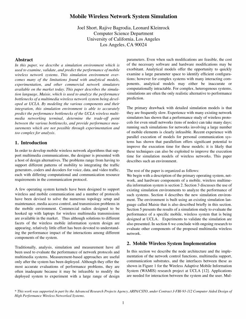
Parameters in TCP which are customizable or tunable include:the backoff algorithm (exponential or linear), initial round triptime (IRTT), maximum segment size (MSS), and the windowsize (WINDOW). The backoff algorithm is designed to providecongestion control throughout the network. The most fair algo-rithm used is an exponential backoff algorithm. However, sincecongestion would not occur in a point to point file transfer (only1 link) this backoff algorithm was replaced with a linear backoffalgorithm. The round trip time is used for determining what thetime-out should be for retransmitting lost packets. This round triptime is based upon an adaptive algorithm which is constantlymeasuring and adapting to the current round trip time. A stabilityparameter is specified which weights the current round trip timewith the average round trip time. Since TCP is responsible forpacketizing the data bit stream, the maximum segment size spec-ifies the maximum packet (segment) size which TCP can gener-ate. IP uses a MTU which specifies the largest packet that can besent over a particular network or link. If the segment size islarger then the packet size then IP does segmentation and reas-sembly of the packet. So, we set the MSS to be 40 bytes less (tocompensate for headers) then the MTU. Finally, the window sizespecifies how much data can be outstanding before an acknowl-edgment is required. The benefit of having a large window is tohandle the case when the latency of the path is significant com-pared to the bandwidth. That is, if you can fit more than 1 packeton the path at a time, then it is useful to have a window so the bitpipe can be filled. For our wireless radios, the latency is insignif-icant compared to the bandwidth so the window should be set toequal the MSS..
The effects of customization on the performance is significant.With standard parameters used on most TCP/IP implementa-tions, the overhead with UCLA’s Radio approaches 99%(depending upon link errors, back-off algorithm, etc.) Given thatcustomization can be achieved through better integration of theprotocols and link level implementation, the question which thispaper addresses is where the remaining bottlenecks are
5.1.3 RFM
The UCLA Direct Sequence Spread Spectrum Modem/Radioused in experimentation and simulation operates at a fixed chiprate of 1.032Mchips/sec. With a spreading factor of 32chips/bit,it is able to achieve a data rate of 32,258bits/sec. A packet inter-
Description Value
SOURCEM TCP BackoffAlgorithm
Linear
SOURCEM File Size 1751560 Bytes
SOURCEM MSS 3960 Bytes
NAM MTU 4000 Bytes
NAM Header Size 71 Bytes
Table 3: SOURCEM & NAM Parameters
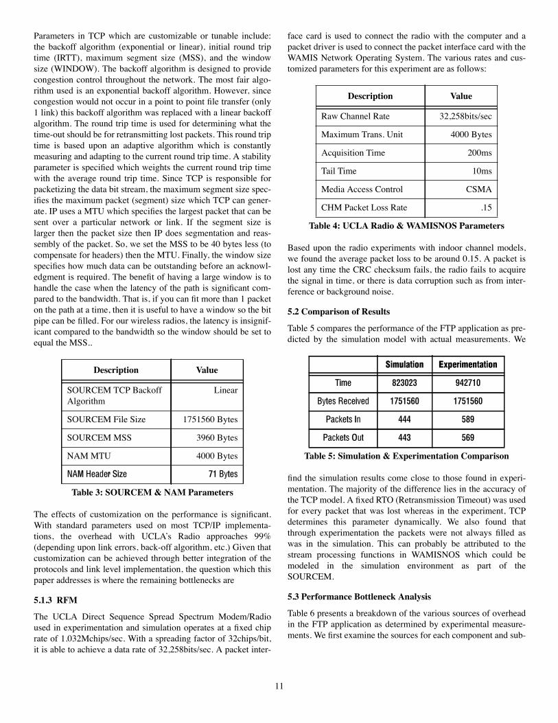
face card is used to connect the radio with the computer and apacket driver is used to connect the packet interface card with theWAMIS Network Operating System. The various rates and cus-tomized parameters for this experiment are as follows:
Based upon the radio experiments with indoor channel models,we found the average packet loss to be around 0.15. A packet islost any time the CRC checksum fails, the radio fails to acquirethe signal in time, or there is data corruption such as from inter-ference or background noise.
5.2 Comparison of Results
Table 5 compares the performance of the FTP application as pre-dicted by the simulation model with actual measurements. We
find the simulation results come close to those found in experi-mentation. The majority of the difference lies in the accuracy ofthe TCP model. A fixed RTO (Retransmission Timeout) was usedfor every packet that was lost whereas in the experiment, TCPdetermines this parameter dynamically. We also found thatthrough experimentation the packets were not always filled aswas in the simulation. This can probably be attributed to thestream processing functions in WAMISNOS which could bemodeled in the simulation environment as part of theSOURCEM.
5.3 Performance Bottleneck Analysis
Table 6 presents a breakdown of the various sources of overheadin the FTP application as determined by experimental measure-ments. We first examine the sources for each component and sub-
Description Value
Raw Channel Rate 32,258bits/sec
Maximum Trans. Unit 4000 Bytes
Acquisition Time 200ms
Tail Time 10ms
Media Access Control CSMA
CHM Packet Loss Rate .15
Table 4: UCLA Radio & WAMISNOS Parameters
Simulation Experimentation
Time 823023 942710
Bytes Received 1751560 1751560
Packets In 444 589
Packets Out 443 569
Table 5: Simulation & Experimentation Comparison
12
sequently compare the experimental results with the simulationresults.
5.3.1 SOURCEM Efficiency
When using the UCLA Radio for the file transfer of the1.7Megabyte file it took 942.71 seconds (as reported by theapplication), with an overall throughput of 1,858 Bytes/Sec. or14,864 bits/sec. This means that the efficiency of the file transferwas about 46%. This can be verified by the following calcula-tion:
We see that the largest percentage of our breakdown is the userdata (efficiency) which is 46%. At first this seems very good thatthe user is able to achieve 46% utilization of the link bandwidth,however the link bandwidth is only 32Kbits/sec so the user isable to achieve 14.7Kbps. If we were able to increase the channelrate, even at the cost of decreasing the link efficiency, we couldachieve a better user throughput. This means that the largest bot-tleneck in getting better performance is the limitation in thetransmission rate (raw channel rate) of the radio (32Kbits/sec.).
5.3.2 RFM Acquisition Time
The second major bottleneck is the acquisition (25%). Each timea packet is transmitted the radio has to go through an acquisitionof the channel which is done by adding on 200ms worth of pre-amble data to the beginning of each packet. It is possible toshorten this preamble time but the error rates and thus retrans-mission of the data increase dramatically causing overall poorerperformance. Besides modifying the required time to acquire thechannel, this overhead can be reduced by decreasing the numberof packets transmitted. The larger the packet size, the lower thenumber of packets, and thus the less overhead for acquiring allthe packets. One of the major factors enforcing the packet size isthe bandwidth-delay trade-off. By increasing the packet size, wecan reduce overhead and increase bandwidth but at the cost ofdelays (and having to retransmit more data). To keep the delaysand memory requirements for storing packets to a minimum, the
Description %
1. User Data Transmission (Efficiency) 46.0
2. Acquisition Time 24.6
3. Time-outs (Packet Loss) 19.8
4. CPU Processing (Rx + Tx) 2.8
5. TCP/IP/WAMIS Headers 2.2
6. Tail Time 1.2
7. Misc. (H/W Proc, CRC Checking, Bit Stuffing, etc.) 3.4
packet size (MTU) is constrained to 4K in the current UCLARadio-WAMISNOS implementation.
The overhead for acquisition was calculated using the followingformula:
WAMISNOS includes the ability to monitor and the number ofWAMIS Packets, IP Packets, and TCP segments sent andreceived at each node. The numbers of TCP segments sent andreceived make up the TotalNumPkts since no segmentation wasnecessary in IP (which would cause generation of more packets),and there weren’t any WAMIS control algorithms running whichwould generate additional packets to the radio. There were 569data packets sent and 589 acknowledgment packets sent. Eachpacket had a 200ms header and the total time for the file transferwas 942.71 seconds or 24.6%.
Tail time is similar to acquisition time; it is the amount of post-amble used on each packet. This is required to ensure that thepacket is completely sent out before the carrier signal is dropped.Experimentation shows that 10ms is an adequate tail time. Thetail time overhead can be calculated similar to the acquisitiontime and is found to be 0.012 of the total raw bandwidth.
5.3.3 SOURCEM Time-outs & CHM Packet Loss
Note that 19.8% of the throughput is lost due to time-outs. Time-outs occur when a packet is lost (the receiver fails to lock ontothe packet or one or more bit errors occur causing the CRC checkto fail and the packet to be discarded) and then the sender mustwait for the time-out period to occur (failure to get an acknowl-edgment) before the packet is retransmitted. The variable time-out period is called the RTO and varies based upon the measuredround trip time of data flowing across the path and then a weight-ing is done for stabilization. Tthe base RTO varies around 2200milliseconds. When a packet loss does occur, the linear backoffalgorithm would increase in the time before the next packet istransmitted. The time-out starts increasing linearly as severalpacket losses occur in a row. If an exponential backoff algorithmwere used, the RTO would have grow exponentially at this pointrather than linearly, making the throughput dramatically worse.
The following algorithm was used as an estimation of the time-out overhead.
During this test, there were 85 packets that had to be retransmit-ted and the average base RTO was around 2200ms so we findTimeoutOverHead to be 19.8%.
5.3.4 OSM Processing
Not as significant as the first three overheads, CPU Processingdoes make an impact on the performance using the UCLA Radio.
Different CPU Processing is done when a packet is either trans-mitted or received at a node.
The Transmitter (Tx) is responsible for taking the bit stream andforming the packets, and putting the header information on it. Weuse a hook in the WAMISNOS system which allows us to watchat what time (in milliseconds) when an acknowledgment of apacket comes in from the packet driver into WAMISNOS anduntil the next packet is transmitted from WAMISNOS to thepacket driver. We found that the average time is 8ms. If we mul-tiply the number of packets sent (569) by the amount of process-ing time (8ms) per packets, we find the transmitter CPUprocessing overhead to be 4.5seconds or 0.5% of the total over-head.,
The receiver (Rx) has to check and remove all the header infor-mation from the packet and verify that the data is correct (pass-ing the CRC check) and create a response (acknowledgment) tothe sender informing that the data was received correctly. It wasmeasured using the trace facility built into WAMISNOS that thetime from when a packet first arrives in WAMISNOS from thepacket driver until the acknowledgment goes out WAMISNOSback to the packet driver around 37ms. Since the TCP/IP proto-cols and the WAMIS Network Operating System are both com-peting for CPU time, along with other applications, protocols,etc., this number can have a high variance, so much that it wouldimpact the performance of any time critical algorithms whichneeded to run at a particular time, such as TDMA. Since 589packets were received and each had to be processed (37ms/pkt)the total overhead imposed by the receiver CPU processing was21.8sec or 2.3% of the overall bandwidth.
The total CPU Processing time is the sender’s overhead (0.5%)plus the receiver’s overhead (2.3%) which totals 2.8%, as isfound in Table 6.
5.3.5 NAM Headers
The application, FTP, uses TCP as its reliable connection ori-ented transport protocol. The TCP protocol packetizes the bitstream into segments and encapsulates it with a TCP controlheader. This TCP header is usually around 20 bytes. The TCPheader contains information such as the source and destinationport (application), the sequence and acknowledgment number, a16 bit checksum, and some miscellaneous flags. TCP sends thesegment down to the IP protocol which encapsulates the segmentinto a packet and puts on its own header of approximately 20bytes. The IP header contains information such as the total lengthof the packet, a 16-bit checksum, an identification field, andsource and destination IP addresses. From here IP sends thepacket down to the WAMIS algorithms which puts on an addi-tional 31 byte header which contains information such as thesource and destination hardware node address, code and powercontrol information, SIR control information, etc. The total TCP/IP/WAMIS headers are usually around 71 bytes.
There were 569 data packets sent and 589 acknowledgment pack-ets sent and at 71 bytes per packet, the total time used up (over-head) in transmitting header information was about 20.4seconds(2.2%). Current research is being done in the Internet Engineer-ing Task Force to come up with a new set of TCP and IP proto-cols which would remove some of the unnecessary informationout of the headers. One such protocol, SIPP (Simple Internet Pro-tocol Plus), would reduce the number of unused bytes in theheader but double the number of usable IP addresses (64 bitsrather then 32.) The unused bytes were introduced since when thestandard was developed, there wasn’t much experience to realizewhich fields were important and which weren’t.
5.3.6 Miscellaneous
There are a number of other miscellaneous factors which add tothe total overhead (3.4%). It was not possible using the currentanalysis and software tools to determine the exact processingtime by the software below the WAMIS Network Operating Sys-tem. This includes the time for the packet driver to activate, cal-culation of a CRC check for the packet, and Carrier SenseMultiple Access. The packet has a start of packet (STX) and endof packet (ETX) marker so the receiver will know the exactbeginning and ending of the packet. Bit stuffing is used to ensurethat none of the data inside the packet would look like one ofthese delimiters. Then the data has to be sent out of the packetinterface card to the modem and from there the processing cantake place to send it out to the transmitter. The opposite processhas to take place on the receiving end.
This overhead was not measured but is the remaining of the over-heads which had not been compensated for in the analysis above.
5.4 Extending Analysis through Simulation
We found that through customization of TCP parameters, wewere able to achieve a link efficiency of 46% (14.8Kbps) usingUCLA’s Radio with WAMISNOS. As shown in Table 7, the three
Description
% of RawChannel Rate(Experiments)
% of RawChannel Rate(Simulation)
1. Data Bandwidth 46.0 52.7
2. Acquisition Time 24.6 21.0
3. Packet Loss & Time-outs
19.8 17.0
4. CPU Processing 2.8 2.0
5. Protocol Headers 2.2 1.8
6. Tail Time 1.2 1.0
8. Other 3.4 4.4
Table 7: Performance Comparison
14
largest bottlenecks in this system are 1) the raw channel rate, 2)acquisition delays, and 3) time-outs in TCP caused by bit errorsand packet losses in the link. We also see that the simulationenvironment breakdown is very similar to that found throughexperimentation.
As technology advancement will allow higher channel rates,other system components will impact the effective data rate. Byusing this simulation environment to test parameter space whichis not possible with current technology, we can see in Graph 1,the trade-off between the effective data rate improvement as theraw channel rate increases.
Various system bottlenecks are preventing the linear growth ofthe effective data rate as a function of the raw cha1nnel rate. InGraph 2, we see how the CPU Overhead becomes a dominant
factor of the raw channel rate around 700Kbps and thus thedecline in the data bandwidth efficiency when the CPU process-ing time is fixed at around 23ms per packet.
As technology will also advance the CPU performance, we cansee in Graph 3 the trade-off between the CPU Overhead and DataBandwidth efficiency of the channel as CPU processing delays(per packet) decrease and the channel rate remains fixed at1Mbps. When the CPU processing delays fall below 17ms perpacket, the channel rate starts becoming the larger bottleneck.
6. Conclusion
Raw Channel Rate (Kbps)
Effe
ctiv
e D
ata
Rate
(Kbp
s)
Graph 1: Effective Data Rate vs. Raw Channel Rate
Raw Channel Rate (Kbps)
% o
f Raw
Ban
dwid
th
Graph 2: Bottleneck vs. Channel Rate
CPU
DataBandwidth
Overhead
This paper described a software architecture for a simulationenvironment for mobile, wireless network systems. The environ-ment provides clearly delineated modules to model each of theprimary components of such as system: network operating sys-tem, traffic models, protocol models of the network, data, andphysical link levels, radio models, and mobility patterns. Theenvironment has been used to perform a number of studies: thispaper described only one simple study that used the NOS, radio,and channel models to evaluate a point-to-point file transfer pro-tocol over a wireless network. A companion paper submitted tothis conference [Gerla, Tsai, Wu] used the protocol and mobilitymodels to evaluate the performance of a clusterhead electionalgorithm as a function of channel characteristics. We plan tointegrate the two preceding models to study the performance ofthe protocols as a function of the radio and NOS characteristics.
The simulation environment was designed using an existing sim-ulation language call Maisie [2]. Maisie has been implementedon both sequential and parallel architectures including distributedmemory machines like the IBM SP2 and shared-memory multi-processor machines like the Sun Sparc 1000. The experimentsreported in this study used only the sequential Maisie implemen-tations. Parallel Maisie implementations have yielded significantperformance improvements for a number of applications thatinclude circuit-simulation [3], queueing networks [1], and dataparallel programs. We intend to explore the viability of the paral-lel implementation in improving the performance of simulationmodels for wireless networks like those described in this paper.
7. AcknowledgmentsWe would like to thank Jack Tsai, Mario Gerla, and Eric Wu fortheir support in developing some of the models used in this simu-lation environment. And everyone in the WAMIS project fortheir contribution in development of the implemented wirelessmultimedia system.
8. References[1] R. Bagrodia, K. M. Chandy, and W-L. Liao, “An Experi-mental Study on the Performance of the Space-Time Algorithm”,Workshop on Parallel and Distributed Simulation, Jan. 1992, pp.158-168.
Graph 3: Bottleneck vs. Processing Delay
CPU
Data
Processing Delays (ms)
Bandwidth% o
f Raw
Ban
dwid
th
Overhead
15
[2] R. Bagrodia, W-L. Liao, “Maisie: A language for designof Efficient Discrete-Event Simulations”, IEEE Transactions onSoftware Engineering, April, 1994.
[3] R. Bagrodia, Li, Z., V. Jha, Y. Chen, and J. Cong, “ParallelLogic-level simulation of VLSI circuits”, 1994 Winter Simula-tion Conference, Orlando, FL, December, 1994.
[4] W. Boring, J. Short, “UCLA WAMISNOS Network Proto-col Programmers Guide”, UCLA Comp. Sci. Dept. TechnicalReport, 950010, April 1995.
[5] S. Chen, N. Bambos, G. Pottie. “Admission controlschemes for wireless communication networks with adjustabletransmitter powers” INFOCOM 94, Toronto, Canada. IEEE1994.
[6] S. Chen, N. Bambos, and G. Pottie, “On Distributed PowerControl for Radio Networks,” IEEE International Conference onCommunication 1994, New Orleans, LA, 1994, pp 1281-1285.
[7] S. Chen, N. Bambos, and G. Pottie, “On Power Controlwith Active Link Quality Protection in Wireless Communica-tions Networks,” IEEE Proceedings 28th Annual Conference onInformation Sciences and Systems.
[8] C. Chien et al., “A 12.7 Mchips/sec All-Digital BPSKDirect-Sequence Spread Spectrum IF Transceiver”, IEEE Jour-nal of Solid-State Circuits, Vol. 29, No. 12, December 1994.
[9] B. Chung, C. Chien, H. Samueli, and R. Jain, “Perfor-mance Analysis of an All-Digital BPSK Direct-SequenceSpread-Spectrum IF Receiver Architecture”, IEEE Journal onSelected Areas in Communications, Vol. 11, No. 7, September1993.
[10] M. Gerla and J. Tsai, “Multicluster, mobile, multimediaradio Network,” accepted for publication in Wireless NetworksJournal.
[11] IP Mobility Working Group, “Routing Support for IPMobile Hosts”, Internet Engineering Task Force, Internet Draft,1994.
[12] R. Jain, J. Short, S. Nazareth, L. Kleinrock, and J. Villase-nor, “PC-notebook based mobile networking: Algorithms, Archi-tectures and Implementation,” IEEE International Conference onCommunication 1995, Seattle, WA, 1995.
[13] C. Lin and M. Gerla, “A Distributed Control Scheme inMulti-hop Packet Radio Networks for supporting Voice/DataTraffic,” IEEE International Conference on Communication1995, Seattle, WA, 1995.
[14] B. Schoner, J. Villasenor, S. Molloy, and R. Jain, “Tech-niques for FPGA Implementation of Video Compression Sys-tems,” ACM/SIGDA International Symposium on Field-Programmable Gate Arrays 1995, Monterey, California, 1995.
[15] J. Villasenor, B. Belzer, and J. Liao, “Wavelet Filter Evalu-ation for Efficient Image Compression,” accepted for publicationin IEEE Transactions on Image Processing, August, 1995.