FBG/36/09 17 May 06 MOD ROADMAPPING GUIDANCE, ISSUE 1.1 “Roadmaps are used to plan the technology needs of projects and identify at an early stage the actions needed to manage the associated technology and obsolescence risk.” chapter 3, paragraph 5, DPA-DLO Technology Management Strategy. Introduction 1. Roadmapping is recognised as an important tool by the DLO, DPA, ECC and SIT communities. Its principle benefit is that it provides both a methodology and a tool to promote sound planning of technology development against Capability needs between MOD organisations, and between MOD and Industry, across the entire CADMID cycle. The roadmapping approach is being adopted and developed widely in industry and throughout the acquisition community. Aim 2. The aim of this guidance is to help the acquisition community understand the principles of roadmapping and assist them in developing specific roadmaps for their projects. Background 3. This guidance is based upon the results of a study 1 conducted by Cambridge University for the Future Business Group within the DPA. The ECC, DLO, DSTL, RAO and Industry were consulted during the study to ensure that the guidance produced is consistent with a pan-acquisition approach. The full report is available on the Future Business Group website - (http://y4.dpa.r.mil.uk/kb/Organisati/SGs/FBG/Sections/Technology/TRM- Guidance_FINAL.doc_cvt.htm ). 4. The aim of this guidance is to help the acquisition community understand the principles of roadmapping and assist them in developing specific roadmaps for their projects. Contents Page(s) What is Roadmapping and what is a Roadmap? 2 Key benefits of Roadmapping and Roadmaps 2 How Roadmaps are different from Project Plans 3 Maturity Model 3 Types of Roadmap 3 Acquisition Roadmap Framework 4 Graphical Roadmap Elements 5 Getting Started - How to generate a Roadmap 6 Good Roadmapping Practice 8 Help and Guidance 9 Example Roadmaps 10 - 12 1 MOD Roadmapping System Guidance v1.0, Cambridge University, 28 January 2005. 1
Transcript
FBG/36/09 17 May 06 MOD ROADMAPPING GUIDANCE, ISSUE 1.1
“Roadmaps are used to plan the technology needs of projects and identify at an early stage the actions needed to manage the associated technology and obsolescence risk.” chapter 3, paragraph 5, DPA-DLO Technology Management Strategy.
Introduction
1. Roadmapping is recognised as an important tool by the DLO, DPA, ECC and SIT communities. Its principle benefit is that it provides both a methodology and a tool to promote sound planning of technology development against Capability needs between MOD organisations, and between MOD and Industry, across the entire CADMID cycle. The roadmapping approach is being adopted and developed widely in industry and throughout the acquisition community.
Aim
2. The aim of this guidance is to help the acquisition community understand the principles of roadmapping and assist them in developing specific roadmaps for their projects.
Background
3. This guidance is based upon the results of a study1 conducted by Cambridge University for the Future Business Group within the DPA. The ECC, DLO, DSTL, RAO and Industry were consulted during the study to ensure that the guidance produced is consistent with a pan-acquisition approach. The full report is available on the Future Business Group website - (http://y4.dpa.r.mil.uk/kb/Organisati/SGs/FBG/Sections/Technology/TRM-Guidance_FINAL.doc_cvt.htm).
4. The aim of this guidance is to help the acquisition community understand the principles of roadmapping and assist them in developing specific roadmaps for their projects.
Contents Page(s)
What is Roadmapping and what is a Roadmap? 2Key benefits of Roadmapping and Roadmaps 2How Roadmaps are different from Project Plans 3Maturity Model 3Types of Roadmap 3Acquisition Roadmap Framework 4Graphical Roadmap Elements 5Getting Started - How to generate a Roadmap 6Good Roadmapping Practice 8Help and Guidance 9Example Roadmaps 10 - 12 1 MOD Roadmapping System Guidance v1.0, Cambridge University, 28 January 2005.
5. Roadmapping is a strategic planning process which helps to align and communicate the business need (Know Why), with the delivery programmes (Know What) and the underpinning resources (Know How). In acquisition terms, it can be used for example to link Capability needs with Equipment projects and Research activities. The roadmapping process was first used in the semiconductor industry in the 1970’s to align technology investments with market and product needs. It is now widespread in industry, with technology companies such as Motorola and Vodaphone now dependent upon it.
6. Roadmaps are the graphical outputs of the roadmapping process, showing the joined up planning between stakeholders. The most common form of roadmap takes the form of a multi-layered time based chart as shown in figure 1. This joint integrated planning approach links resources and activities with the business goals – which in acquisition terms can be summarised as capability needs.
7. A Roadmap shows the strategic plan for the identification, evaluation and maturation of alternative technological solutions for achieving a requirement and the route by which these may be embodied in military systems. It applies throughout the CADMID cycle whether the technology is to be incorporated into a new design or inserted into an existing programme post Main Gate.
Figure 1
Key Benefits of Roadmapping and Roadmaps
8. Roadmapping is a powerful management technique. Good roadmaps help deliver effective technology exploitation, acquisition and insertion. Roadmapping identifies key synergies, dependencies and gaps within a strategic plan, in order to expose risks or issues more readily. Roadmapping enables more effective decision making, through better communication, clarity of thinking, alignment and visibility of programmes or activities. Roadmaps can help to reduce risk to a degree consistent with delivering an acceptable level of system performance to required time and cost targets.
2
9. Above all, roadmaps support communication and are particularly effective across disparate teams and organisational boundaries. Within acquisition, roadmaps are effective tools to ensure joined up technology planning between Customer One, the Research Community, Acquisition Teams and Industry.
How Roadmaps are different from Project Plans
10. Roadmaps are generally concerned with longer timeframes than the project plans typically produced by MicroSoft Project. Roadmaps deal with more strategic levels of information, and as such are often concerned with navigating through areas of high uncertainty. The multi-layered approach differentiates a roadmap from a project plan, helping to present information in a way that aids understanding of the linkages and dependencies between activities.
Maturity Model
11. Roadmapping can be characterised in terms of a maturity model:
a. Level 1. Roadmaps support communication and common understanding.
b. Level 2. Roadmaps are of sufficient quality that they can be used to influence decisions or persuade people to change their views or behaviour.
c. Level 3. A system of roadmaps has been developed that supports synchronisation and alignment across the organisation.
12. Many parts of the MOD are already developing good roadmaps (e.g. to support Initial Gate submissions or release research funding) and this can be characterised as sitting between levels 1 & 2 described above. Key enablers to achieving level 3 maturity are common architectures and data formats, which are described further in this document. A Roadmapping Community of Practice2 has been set up to support convergence towards the common approach described at level 3 above; this forum also supports and encourages the sharing of best practice and discussion on the subject of roadmapping generally..
Types of Roadmap
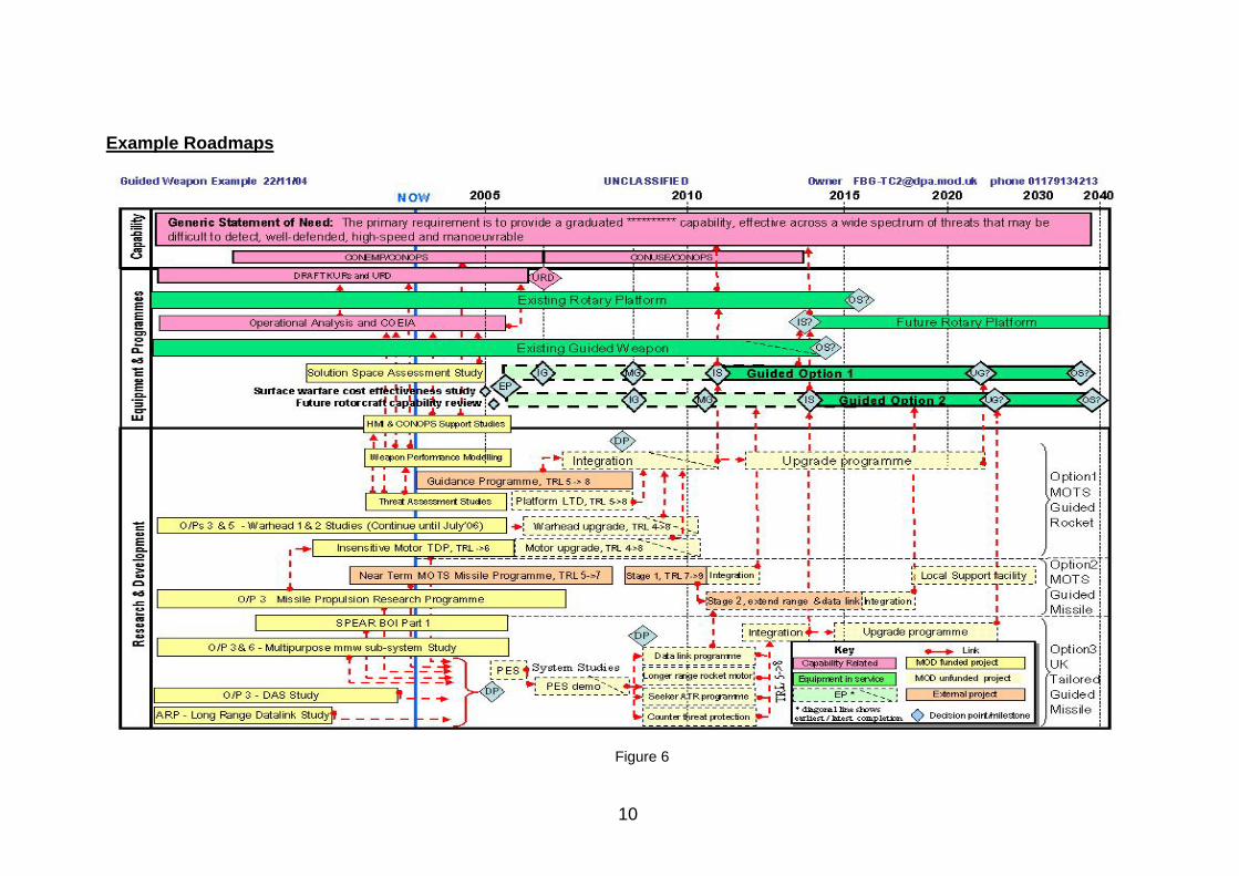
13. Within Acquisition, three basic types of roadmap have been identified and associated with different core processes and stakeholder groups (see figure 2). These roadmaps are not independent in that they share a common roadmap architecture and display common information, such as capability shortfalls, platform in/out service dates and research programme information. These roadmap views are illustrative and should not be viewed as three discrete types. When a roadmap is being created for a specific purpose, teams should not feel constrained by these three views. The examples at the end of this guidance are real examples of roadmaps created by project teams, and do not fit neatly into either of these views.
2 Accessible from the DPA Knowledge Base / Communities / Roadmapping
3
Figure 2
a. Capability roadmaps support the processes leading up to development of the User Requirements Document (URD). These roadmaps can be considered ‘capability centric’ in that the primary unit of analysis is a particular capability need, with the owner of the roadmap typically residing within the Equipment Capability Customer (ECC) organisation. This type of roadmap generally contains links to multiple systems, equipment types, technologies and possibly other capability areas.
b. Exploitation roadmaps support the management of the programmes required to deliver the required capability through equipment programmes or other lines of development (LOD). These roadmaps can be considered ‘equipment/other LOD’ centric in that the primary unit of analysis is a particular system/platform or other line of development. The owner is likely to reside in the DPA or the DLO.
c. Technology roadmaps support the management of technology research and development programmes. These roadmaps can be considered to be ‘technology centric’ in that the primary unit of analysis is a particular technology area or programme, with the owner typically residing within the Research Acquisition Organisation (RAO) or the Defence Science and Technology Laboratories (DSTL).
14. What is common to all three roadmap types (or ‘views’) is that they share a common architecture flexible enough to be adapted for each particular purpose, and they use a standard set of graphical elements. The standard framework and the standard graphical elements are discussed in more detail later in this document.
Acquisition Roadmap Framework
15. The use of a standard roadmapping framework enables information to be shared more effectively across the acquisition community – it should be thought of as a framework within which key information and relationships can be captured, stored and communicated. The general MOD-wide framework developed as part of the roadmapping study is shown
4
in figure 3, focusing on the Equipment Line of Development (LOD), with a mapping shown on the right hand side against the MOD Technology Taxonomy3.
Figure 3
16. The roadmapping framework defined by these layers is not intended to be too prescriptive. Rather the developers of roadmaps should configure the structure of the roadmap to suit the particular application under consideration, using these principles as a starting point. Several examples of roadmaps based on this framework are shown at the end of this guidance.
17. A relevant Capability or R&D level roadmap may already have been created, and EC or RAO stakeholders will be able to provide these and discuss the linkages with the Equipment roadmap. If no separate R&D or Capability roadmap exists, these stakeholders will be able to provide the details necessary to include these views in the overall Acquisition roadmap framework.
Graphical Roadmap Elements
18. The following set of four graphical roadmap elements (shown in figure 4) is the minimum sufficient to create a roadmap:
Activity, equipment, concept, etc
‘Tapered bars’ can beused to indicate the
range of likely start andcompletion dates Decision
point
Linkages(relationships & causality)
Set (e.g. NEC)Milestone
Linkages must not go backwards
a. Bars - activities, projects, platforms, concepts, future programmes and other entities that occur over a period of time. ‘Tapered bars’ can be used to show the likely range of start and completion dates (e.g. 10% and 90% confidence levels). Note that current best practice uses dotted lines to indicate unfunded tasks.
Figure 4
3 MOD Technology Taxonomy, Version 6, 2004
5
b. Diamonds - decision points, milestones, objectives and forecasts that occur at a single point in time.
c. Arrows - linkages, connecting roadmap elements, to map relationships.
d. Sets - or collections of elements which cannot be easily shown as related by other means such as the use of colour - e.g. projects and activities in a programme, or a set of systems that together contribute to a network-enabled capability (see dotted line in figure 4).
e. A key for any colours, acronymns and line styles used is essential to aid understanding of your roadmaps.
19. The full consideration of data that could be associated with these graphical elements (‘metadata’) is described in the full Cambridge University report and may include information such as: Title of element; Description or summary of element; ‘Owner’ (the person or group responsible for maintaining the element or data); Time frames (e.g. start and finish dates); Technology Readiness Levels; Taxonomy references; Status (e.g. funded or not funded); References to other key documents or roadmaps; Security classification. Consideration of the data architectures to be used across MOD is the responsibility of the Roadmapping Community of Practice.
Getting Started – How to Generate a Roadmap
20. Often a small group of individuals can produce a detailed roadmap in short and focussed meetings. For more complex cases or those involving a large group of stakeholders, workshops provide a useful mechanism to bring together the range of stakeholders that need to be involved. This enables the communication and buy-in, data collection and creativity, particularly at early stages of the process.
21. Cambridge University have developed a ‘fast start’ process for introducing the roadmapping approach in organisations. This process is called ‘T-Plan’ and is based on a workshop approach. This approach has been customised for the MOD and details are contained in the full report (annex D) on the FBG website. In simple terms, the process uses the low-tech approach of ‘post-it’ notes to capture key information and map this on the outline roadmap structure shown in figure 3. The photograph in figure 5 shows this approach in action – it was taken during one of the study pilot roadmapping sessions. A summarised version of this approach is shown here, showing the key planning and workshop steps involved:
a. Define the reason for developing the roadmap – the problem.
b. Define the boundaries – what is being considered and what is not.
c. Define the aims of the roadmap – why is the roadmap being developed?
d. Ensure that the correct people are in attendance to construct the roadmap – e.g. the example shown in figure 6, involved representatives from the DEC (capability) IPT (equipment project) and DSTL (science & technology).
e. Use a facilitator who is clear about the purpose of the roadmapping session and is able to focus and capture the brainstorming involved.
6
f. Ensure attendees come prepared to brief the group should their specific knowledge be required to get people started.
g. Define the structure of the roadmap using the generic models shown in figures 1 and 3 as a guide – a non-linear timescale and three broad layers are appropriate.
h. Construct a large paper version of this outline structure and attach it to the wall so that all in attendance can see it.
i. Focus on the layer of interest (e.g. for exploitation roadmap the middle layer) - capture the key activities on ‘Post-it’ notes and place them on the outline paper roadmap.
j. Capture the key information about each activity – e.g. start & completion date, activity name and TRLs or taxonomy references, if applicable
k. Link activities appropriately on the chart with a pen, and capture any relevant information about the nature of the activities or links.
l. Populate the rest of the roadmap layers in a similar fashion capturing related activities (e.g. underpinning technology development or research programmes and capability gaps or related capability areas). Again link appropriately.
m. A first cut roadmap can then be produced from the paper version, using MS PowerPoint or another suitable tool.
n. Capture all relevant supporting information and produce a paper (the ‘strategic narrative’) outlining key background information that complements the summary information contained in the roadmap.
o. Circulate the first cut roadmap and the ‘strategic narrative’ and refine it and update it using additional workshops accordingly.
Figure 5
7
22. A workshop is of particular use when it is desirable to involve a reasonably large group of stakeholders, to share knowledge and gain buy-in. However some activities are best undertaken in small groups. For example, the illustrative roadmaps contained in this document were created in small group sessions, usually involving four or five people over periods of a few hours. In each case, the roadmap framework (similar to above) was populated with information, drawing on programme and technical documentation supported by expert knowledge and discussion within the group. From this, MS PowerPoint was used to produce the (sanitised for security purposes) roadmaps shown at the end of this document.
Good Roadmapping Practice
23. At the early stages, roadmaps are likely to have gaps and inconsistencies, but the quality of the roadmap should improve over time as the strategic plan matures. Consultation with key stakeholders is vitally important, and the roadmap provides a mechanism to support this dialogue. Discussion with customers and suppliers (particularly industry) is vital, to clearly understand requirements and constraints, and to understand potential acquisition routes, capability and technological options. Several observations on what a good roadmap should contain have emerged from the study and best practice:
a. A roadmap should include a title and security classification, together with name and contact details for the owner and date that the roadmap was last updated;
b. The architecture should be compatible with the principles set out in this guidance, in terms of three broad layers;
c. A key should be included to explain the meaning of symbols and colours;
d. A full life cycle view of equipment and platforms should be shown;
e. Colour or other appropriate means should be used to show clearly the funding status of research or development programmes;
f. In general, a non-linear scale for time is appropriate, with more space given to the short-term compared to the long-term;
g. Clear links should be shown to delivered capability, which may require consideration of additional equipment, systems or platforms (for example if the IPT is working on equipment that will be inserted into another platform);
h. Clear links between research projects should be shown, and how these feed into equipment programmes;
i. The roadmap should include key milestones and decision points, for example, an exploitation roadmap should include Initial Gate, Main Gate, In-Service and Out-of-Service dates;
j. Elements should be coded with brief titles and Technology Readiness Levels (for technology research and development), together with an indication of the ‘window of availability’ when the programme is likely to be completed (e.g. 10% and 90% confidence limits);
8
9
k. Supporting text should be provided (usually in a supporting document) to complement the roadmap, describing the scope and aims of the roadmap, defining terms and presenting the ‘strategic narrative’, including options, tradeoffs and risks.
Help & Guidance
24. This guidance does not yet extend to recommendations on either specific processes within Acquisition management where roadmapping should be applied, or on specific roadmapping tools, beyond the articulation of general principles. Work is on ongoing through the Roadmapping Community of Practice within each of the acquisition communities to agree a set of common processes and supporting roadmapping tools to support them.
25. PowerPoint, Excel and Visio are sufficient to produce static roadmaps (a single view at a particular point in time); all the diagrams in this document were produced using these tools. In many cases however, a dynamic roadmapping tool (underpinned by a database) is required.
26. Prior to developing a roadmap, you are encouraged to contact your local roadmapping focal point:
a. DPA/DLO users should contact FBG-TC2, [email protected], phone: (9)352 34213);
b. ECC users should consult with EC DCT-Outputs, phone (9)621 82281);
c. RAO users should contact SIT RAO-TD1, (9)6161 4018.
Statement of Need: The primary require is to provide a graduated capability that is effective across a wide spectrum of threats some of which may be high-speed and maneouvrable.
Equipt Option 1
Equipt Option 2
Platform HMI. TRL 1/2->3/4
Research Phase 1TRL 1/2->3/4
Seeker DevelopmentTRL 4->6
MotorTRL 5/6->6
Extended RangeTRL 3/4->8
Platform Integration & ClearanceTRL 7/8->8
Future SeekerTRL 2/3->8
Multi-EffectTRL 2->8
In Service Kit
WarheadTRL 4->6
ClearanceTRL 7/8->8
Simulation / EmulationTRL 2->4
EP08 Funding? Apr 08
Option Research.TRL 1/2->4
Res
earc
h &
Dev
elop
men
tO
ptio
n 1
Opt
ion
2
Definition Study.TRL 1->2/3
IPT Allocation: Mar 06
IPT Allocation: Jun 08
MG: Dec 10
Option Study. 1->2
I2005
I2006
I2007
I2008
I2009
I2010
I2011
I2012
I2013
I2014
I2015
I2020
I2025
I2030
I2035
I2040
I2045
IG: Aug 09
Dstl Consolidated AdviceTRL 1/2->2/3
Research Phase 2aTRL 2->3
M1 - UR108M8 - UR18K1 - UR78K2 - UR120K8 - UR59
OSD: Jun 14
OSD: 2045
EP 06 Funding
MG: Aug 10 OSD: 2045
ISD: Aug 12
IOC: Aug 14
Other project Motor integration(reduced performance)TRL6
MLU: 2030??ISD: Apr 17??
No fundingavailable
IG: May 08
Technology DevelopmentTRL3->7
Technology DevelopmentTRL4->7
Technology DevelopmentTRL7->8 Key:
Output 6
Project funded
Other EP line Not Funded
Dstl
Dstl(via Project tasking)
MLU: Mid-Life Update
Key RiskDecision Point
ECHNOLOGY XAMPLE OADMAPV1.0 17 May 2006, [author]
[SECURITY CLASSIFICATION]
[SECURITY CLASSIFICATION]
Figure 7
Figure 8
2005 2006 2007 2008 2009 2010 2015 2020 2040
Capability
NEC
Equipment &Programmes (IPTs)
Tech
nolo
gy
Air V
ehicl
e
Com
mun
icatio
nsSe
nsor
Sys
tem
Envir
onm
enta
lPr
otec
tion
Othe r
Single Statement of User Requirement: XXX will provide XXX to satisfy XXX requirements, within the context of XXX, throughout a range of XXX and across XXX
Programme of interest MG IOC OSRFFOCBS2
Equipment 1
Equipment 2
Equipment 4
Equipment 3IS
System 1(interoperability)
Additional sensorinformation
MainlySoftwareUpgrades
New Air Vehicle
New Platform
Commonality?
System 1 (TRL6)
Encryption
DP Y(System 1 vs OTS)
System 2 (TRL4) DP Y(System 2 vs OTS)
System 3 (TRL6-7) 9 DP Y(System 3 vs non-UK OTS)
System 1 (TRL6) YN Fallback Technology 1 (TRL8)
Fallback Technology 1
Y
N
Y
8 9
8 9Complete
Flight trails
BS2 finalqualification
Flight trailscomplete
BS1qualification
6
N
NFallback Technology 1 Integration
Emulator
sin p
lace
9BS2qualification
8
Weight
Reduced
9
7 8DP 9In-S
ervice
System 1 (TRL5) DP
System 2 TRL9
Fallback Technology 1 (TRL7) Integration
Icing T
unnel
Tests Fligh
t
Tests 1 Fligh
t
Tests 2
Prov
en w
ithMi
ssion
s
FutureInsertion
N Technology 1 (TRL7)DPNew Launch Method ?
Integration
Airworth
iness
Certifica
tion
Flight Trial
s
Engine Modifications
Planning to bring forward System 2for embodiment in Build Standard 1 (IOC)
Requires 000s
flight hours
DesignDevelopment
DP
Stealth ?Sustainability Increase
Programme 1IS
Programm
e 1 drives future
capability requirements
Midlife Refresh
enhances capability
Fallback Technology 2 Integration
Completelab testing
Fallback Technology 3 Integration
Endurance - weight
Enhanced Sensors
Capability
UK R&D Programme
Non-UK R&D Programme
Decision point / milestone
Equipment / Platforms
KeyCom
plete
Flight tra
ils Joint
Flight tra
ils
Build Standard 2 (BS2)
N
OR
(System 1 vs non-UK OTS)
Y
Fallback Technology
(System 1 vs non-UK Technology)6 7 8 9
Example focused on a specific system (air vehicle) withina larger equipment project. 10/03/05