Marquette University | Milwaukee School of Engineering | Purdue University | University of California, Merced | University of Illinois, Urbana-Champaign | University of Minnesota | Vanderbilt University Modal Parameter Estimation of hydraulic Axial-piston pumps and Motors Paul Kalbfleisch, Researcher Purdue University Monika Ivantysynova Fluid Power Innovation & Research Conference October 10-12, 2016
Transcript
Marquette University | Milwaukee School of Engineering | Purdue University | University of California, Merced | University of Illinois, Urbana-Champaign | University of Minnesota |
Vanderbilt University
Modal Parameter Estimation of hydraulic
Axial-piston pumps and Motors
Paul Kalbfleisch, Researcher
Purdue University
Monika Ivantysynova
Fluid Power Innovation & Research Conference
October 10-12, 2016
2FPIRC16
Vibro-
Acoustics
VibroacousticsRadiationPropagation
0 100 200 300
20
40
60
80
100
120
Displacement Chamber Pressure
Angle [°]
Pre
ssure
ΔP
[bar]
Pump noise modeling
3FPIRC16
Project Overview Major
Objectives/Deliverables
Next Steps
• Goal: Incrementally validate noise
modeling techniques with experimental
results.
• CCEFP: Thrust Area 3, Effectiveness:
Noise and vibration, leakage,
contamination and human factors.
• Contribution: Understand the
generation of noise by swash plate
type axial piston machines.
• Handful of competing researchers.
• Large simulation errors
• Lack sufficient experimental
validation
• Complete experimental modal
analysis (month 3)
• Measure displacement chamber and
port pressures to verify current
hydraulic model (month 6)
• Can industry donate a laser
vibrometer?
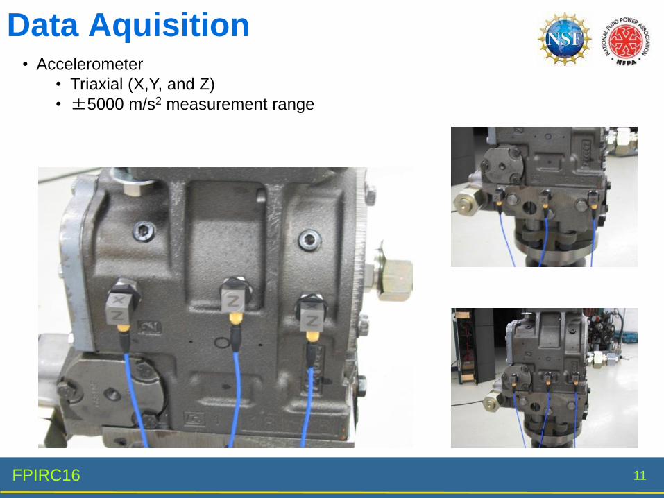
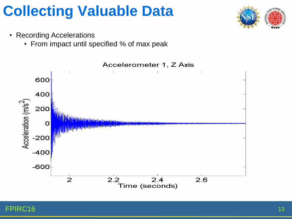
• Set of measurements that include:
• Displacement chamber pressure
• Acceleration on the casing
• Modal parameter estimation
• Sound intensity
• Better understand how internal pressure
forces transmit to external audible noise
4FPIRC16
Cremer, L., Heckl, M. and Petersson, B. A. T., 2005. Structure-borne Sound: Structural
Vibrations and Sound Radiation at Audio Frequencies. Berlin: Springer.
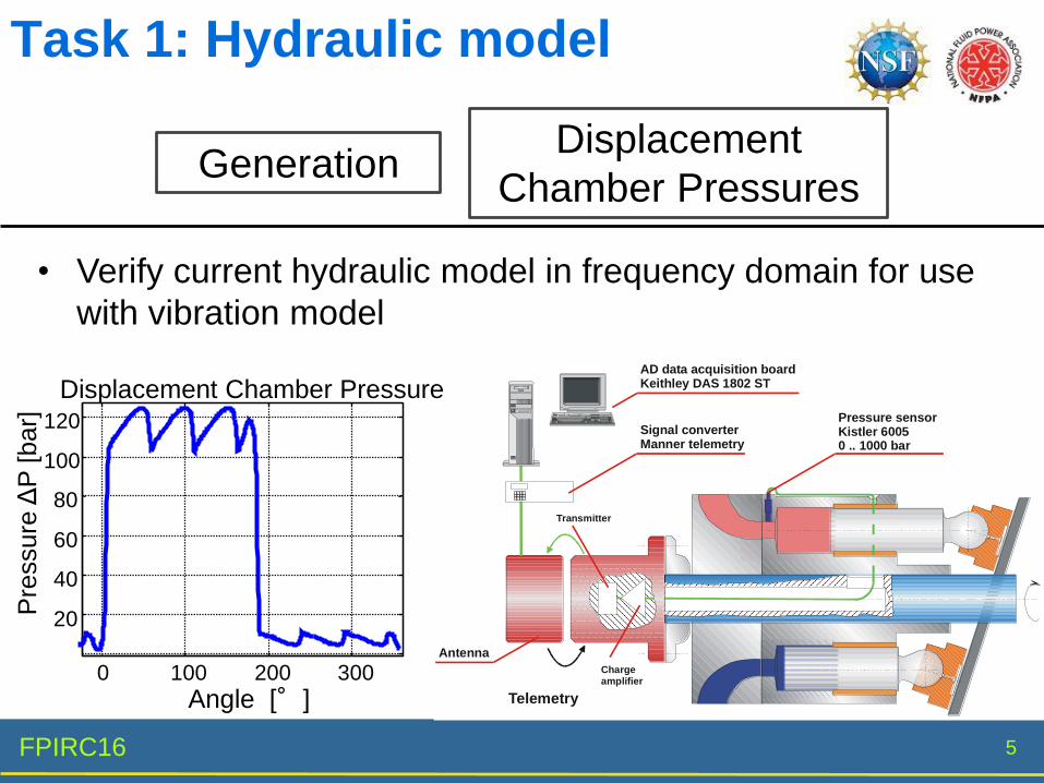
GenerationDisplacement
Chamber Pressures
Radiation Case to Air
Propagation Wave Travel
Transmission Active to passive
Structural Acoustic Process
5FPIRC16
Task 1: Hydraulic model
GenerationDisplacement
Chamber Pressures
Telemetry
Transmitter
Antenna
AD data acquisition boardKeithley DAS 1802 ST
Pressure sensorKistler 60050 .. 1000 bar
Chargeamplifier
Signal converterManner telemetry
0 100 200 300
20
40
60
80
100
120
Displacement Chamber Pressure
Angle [°]
Pre
ssure
ΔP
[bar]
• Verify current hydraulic model in frequency domain for use
with vibration model
6FPIRC16
Task 2: Vibration model
Propagation Wave Travel
Transmission Active to passive
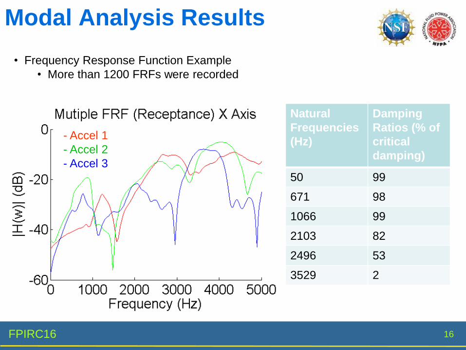
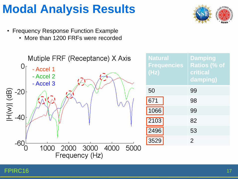
• Experimental Modal analysis
• FEM model of the hydraulic pump case
• Utilize forces found in Task 1 for FEM analysis
• Compare measured pump case vibration to
simulation results
7FPIRC16
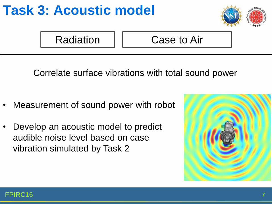
Task 3: Acoustic model
Radiation Case to Air
Correlate surface vibrations with total sound power