Modbus Interface RTD › Indoor unit control via 0~10 volt, dry contact or resistance contact › Retail applications › Hotel applications › IT applications › Heating interlock › Alarm signal Split, Sky Air, VRV, Chillers, Refrigeration, Daikin Altherma Integration of Daikin portfolio in BMS system via Modbus
Transcript
Modbus Interface RTD
› Indoor unit control via 0~10 volt, dry contact or resistance contact
› Retail applications › Hotel applications › IT applications › Heating interlock › Alarm signal
Split, Sky Air, VRV, Chillers,
Refrigeration, Daikin Altherma
Integration of Daikin portfolio in BMS system via Modbus
2
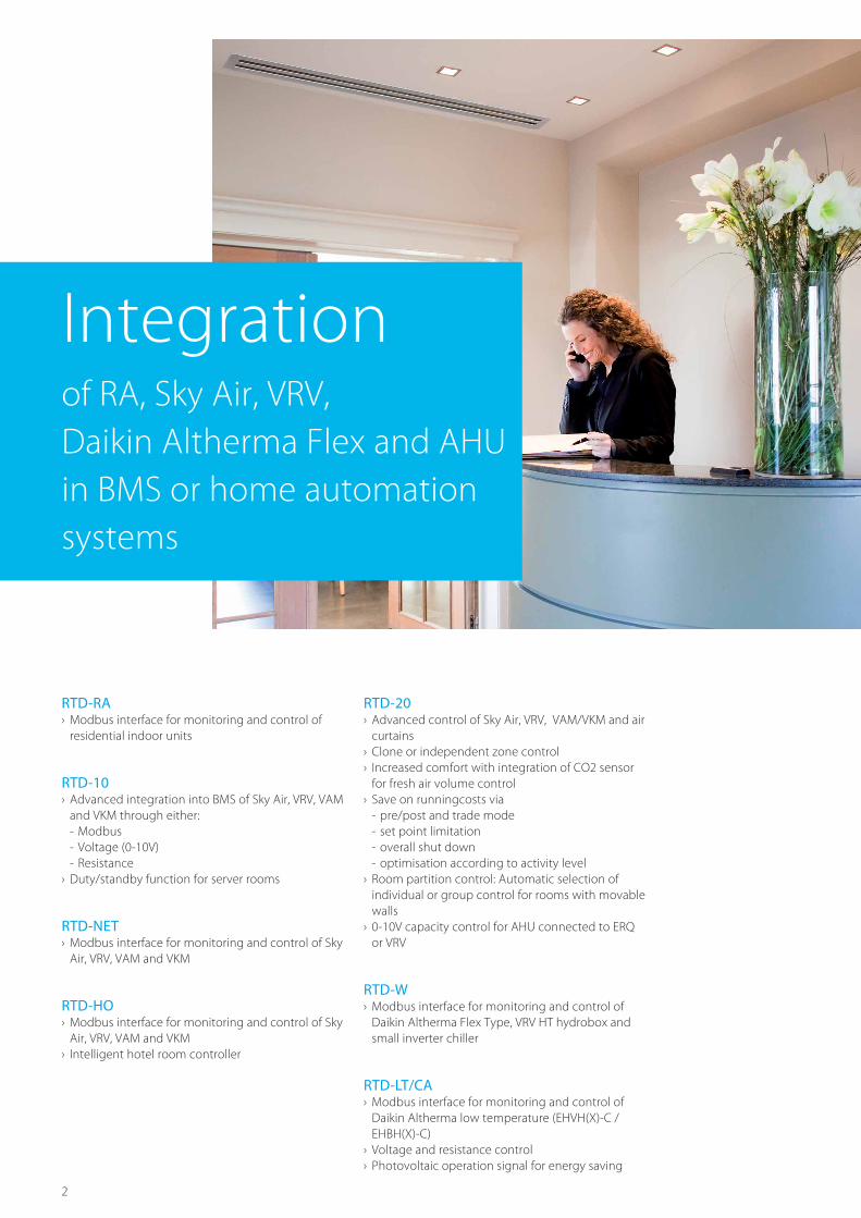
RTD-RA › Modbus interface for monitoring and control of residential indoor units
RTD-10 › Advanced integration into BMS of Sky Air, VRV, VAM and VKM through either: - Modbus - Voltage (0-10V) - Resistance
› Duty/standby function for server rooms
RTD-NET › Modbus interface for monitoring and control of Sky Air, VRV, VAM and VKM
RTD-HO › Modbus interface for monitoring and control of Sky Air, VRV, VAM and VKM
› Intelligent hotel room controller
RTD-20 › Advanced control of Sky Air, VRV, VAM/VKM and air curtains
› Clone or independent zone control › Increased comfort with integration of CO2 sensor for fresh air volume control
› Save on runningcosts via - pre/post and trade mode - set point limitation - overall shut down - optimisation according to activity level
› Room partition control: Automatic selection of individual or group control for rooms with movable walls
› 0-10V capacity control for AHU connected to ERQ or VRV
RTD-W › Modbus interface for monitoring and control of Daikin Altherma Flex Type, VRV HT hydrobox and small inverter chiller
RTD-LT/CA › Modbus interface for monitoring and control of Daikin Altherma low temperature (EHVH(X)-C / EHBH(X)-C)
› Voltage and resistance control › Photovoltaic operation signal for energy saving
Integration of RA, Sky Air, VRV, Daikin Altherma Flex and AHU in BMS or home automation systems
3
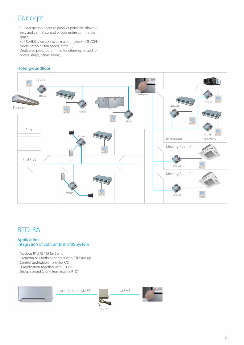
Concept › Full integration of entire product portfolio, allowing easy and central control of your entire commercial space
› Full flexibility (access to all main functions) (ON/OFF, mode, setpoint, fan speed, error… )
› Dedicated pre-programmed functions optimzed for hotels, shops, server rooms, ...
RTD-RA Application: Integration of Split units in BMS system
› Modbus RTU RS485 for Splits › Harmonized Modbus registers with RTD line-up › Control prohibition from the R/C › IT application together with RTD-10 › Group control (clone from master RTD)
Hotel groundfloor
Restaurant Kitchen
Meeting Room 1
Meeting Room 2
Stair
Lobby
Entrance
RTD-NET
RTD-NET
RTD-20
BMS system
RTD-HO
RTD-HO
RTD-NET
RTD-20
RTD-20
RTD-NET
RTD-NET
First Floor
to indoor unit via S21 to BMS
RTD-RA
4
RTD-10 Application: Duty/standby function for server rooms
› Suitable for IT and Telecom applications. › Rotation function: • Up to 8 duty/standby groups • 1 or 2 standby units /groups • Daily or Weekly duty rotation • Optional thermistor space temperature alarm
› Back up function › Two level alarm on high temperature or unit fault
Application: Heating interlock of air conditioning with central heating
› Avoids having simultaneous cooling and heating occurring when a separate heating system is installed
› Master option: the heating system is switched off based on the operation of the indoor unit
› Slave option: certain indoor unit functions are block, the unit is switched it or the mode is changed to fan only when the heating system is operating
Application: Integration in BMS system
› Integration in BMS system via resistance and/or voltage control
Rotation function Two level alarm
STANDBY STANDBY
STANDBY STANDBY
STANDBY STANDBY STANDBY STANDBY
RUN
high level
alarme.g. 25°c
low level
alarme.g. 23°c
set point room temp: 20°c
Back up function
STANDBYSTANDBY
STANDBY STANDBY
critical alarm
critical alarm
To indoor unit power supply
From BMS system (resistance/voltage)
Fault signal to BMSTo indoor unit
via P1/P2
Indoor unit is switched off
To indoor unit via P1/P2
5
RTD-NET Application: Integration in BMS system via Modbus control
› Integration in BMS system via Modbus
RTD-HO Application: Hotel room
› Interlock with key card › Interlock with window contact › Control via third party remote control › Limit selectable setpoint › Prohibit several remote control settings like indoor unit on/off , indoor unit mode …
To indoor unit power supply
To BMS system (Modbus)
To indoor unit via P1/P2
Upper temperature limit 27°C Upper limit selectable setpoint 24°C Selected setpoint by guest 22°C Lower limit selectable setpoint 19°C Lower temperature limit 18°C
Indoor temperature
SAVE ENERGY (SUMMER)
SAVE ENERGY (WINTER)
Room occupied Guest leaves room
Guest returns to room
Example with keycard connection(cooling)
To indoor unit power supply
Key card
Window contact
Modbus
Third party remote control
To indoor unit via P1/P2
6
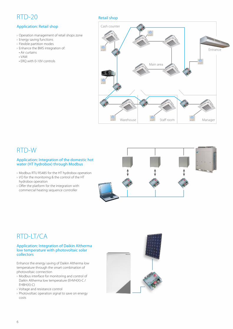
RTD-20 Application: Retail shop
› Operation management of retail shops zone › Energy saving functions › Flexible partition modes › Enhance the BMS integration of: • Air curtains • VAM • ERQ with 0-10V controls
RTD-W Application: Integration of the domestic hot water (HT hydrobox) through Modbus
› Modbus RTU RS485 for the HT hydrobox operation › I/O for the monitoring & the control of the HT hydrobox operation
› Offer the platform for the integration with commercial heating sequence controller
RTD-LT/CA Application: Integration of Daikin Altherma low temperature with photovoltaic solar collectors
Enhance the energy saving of Daikin Altherma low temperature through the smart combination of photovoltaic connection › Modbus interface for monitoring and control of Daikin Altherma low temperature (EHVH(X)-C / EHBH(X)-C)
› Voltage and resistance control › Photovoltaic operation signal to save on energy costs
Cash counter
Warehouse Staff room Manager
Main area
Entrance
Retail shop
7
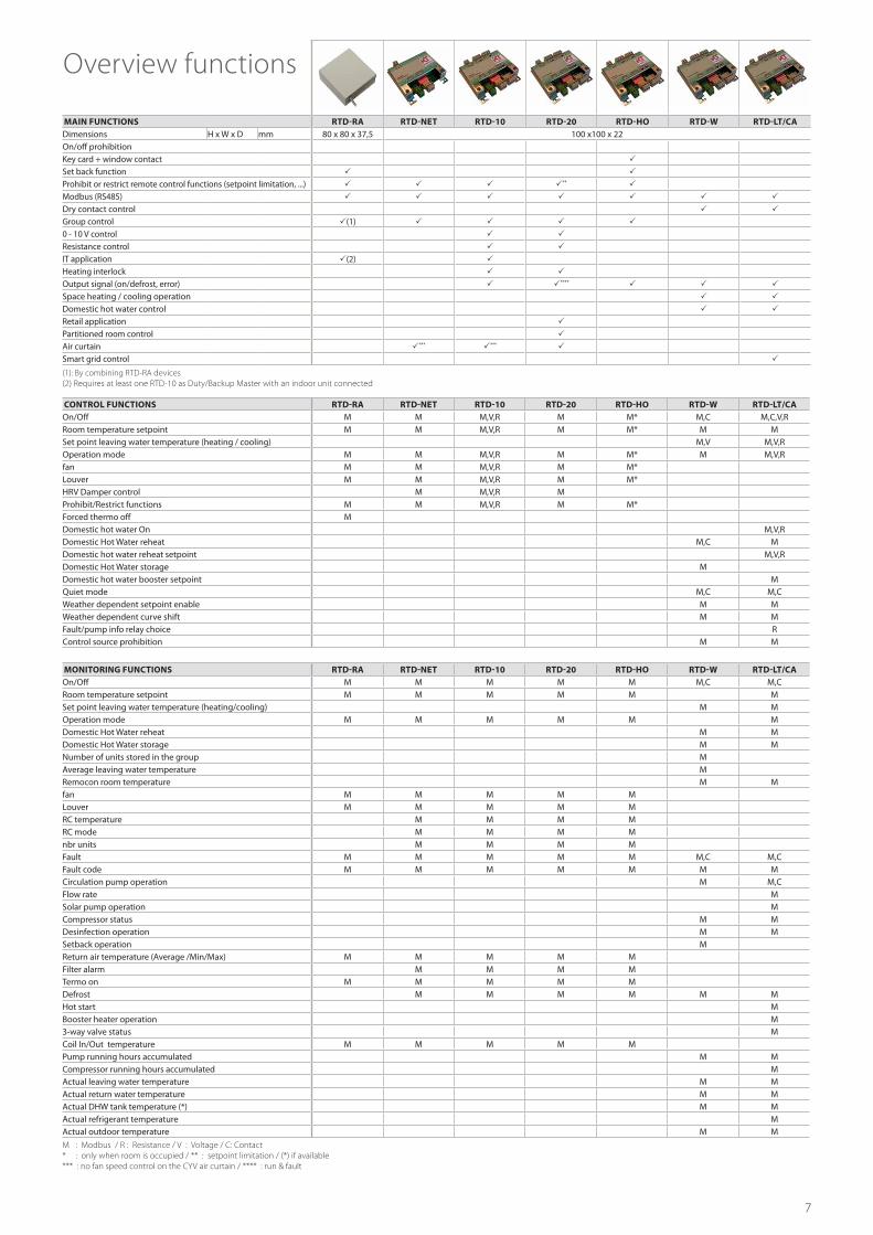
CONTROL FUNCTIONS RTD-RA RTD-NET RTD-10 RTD-20 RTD-HO RTD-W RTD-LT/CAOn/Off M M M,V,R M M* M,C M,C,V,RRoom temperature setpoint M M M,V,R M M* M MSet point leaving water temperature (heating / cooling) M,V M,V,ROperation mode M M M,V,R M M* M M,V,Rfan M M M,V,R M M*Louver M M M,V,R M M*HRV Damper control M M,V,R MProhibit/Restrict functions M M M,V,R M M*Forced thermo off MDomestic hot water On M,V,RDomestic Hot Water reheat M,C MDomestic hot water reheat setpoint M,V,RDomestic Hot Water storage MDomestic hot water booster setpoint MQuiet mode M,C M,CWeather dependent setpoint enable M MWeather dependent curve shift M MFault/pump info relay choice RControl source prohibition M M
MAIN FUNCTIONS RTD-RA RTD-NET RTD-10 RTD-20 RTD-HO RTD-W RTD-LT/CADimensions H x W x D mm 80 x 80 x 37,5 100 x100 x 22On/off prohibitionKey card + window contact
Set back function
Prohibit or restrict remote control functions (setpoint limitation, ...) **
Modbus (RS485)
Dry contact control
Group control (1)
0 - 10 V control
Resistance control
IT application (2)
Heating interlock
Output signal (on/defrost, error) ****
Space heating / cooling operation
Domestic hot water control
Retail application
Partitioned room control
Air curtain *** ***
Smart grid control
Overview functions
MONITORING FUNCTIONS RTD-RA RTD-NET RTD-10 RTD-20 RTD-HO RTD-W RTD-LT/CAOn/Off M M M M M M,C M,CRoom temperature setpoint M M M M M MSet point leaving water temperature (heating/cooling) M MOperation mode M M M M M MDomestic Hot Water reheat M MDomestic Hot Water storage M MNumber of units stored in the group MAverage leaving water temperature MRemocon room temperature M Mfan M M M M MLouver M M M M MRC temperature M M M MRC mode M M M Mnbr units M M M MFault M M M M M M,C M,CFault code M M M M M M MCirculation pump operation M M,CFlow rate MSolar pump operation MCompressor status M MDesinfection operation M MSetback operation MReturn air temperature (Average /Min/Max) M M M M MFilter alarm M M M MTermo on M M M M MDefrost M M M M M MHot start MBooster heater operation M3-way valve status MCoil In/Out temperature M M M M MPump running hours accumulated M MCompressor running hours accumulated MActual leaving water temperature M MActual return water temperature M MActual DHW tank temperature (*) M MActual refrigerant temperature MActual outdoor temperature M M
M : Modbus / R : Resistance / V : Voltage / C: Contact* : only when room is occupied / ** : setpoint limitation / (*) if available*** : no fan speed control on the CYV air curtain / **** : run & fault
(1): By combining RTD-RA devices (2) Requires at least one RTD-10 as Duty/Backup Master with an indoor unit connected
FSC
The present publication is drawn up by way of information only and does not constitute an offer binding upon
Daikin Europe N.V. Daikin Europe N.V. has compiled the content of this publication to the best of its knowledge. No
express or implied warranty is given for the completeness, accuracy, reliability or fitness for particular purpose of its
content and the products and services presented therein. Specifications are subject to change without prior notice.
Daikin Europe N.V. explicitly rejects any liability for any direct or indirect damage, in the broadest sense, arising from
or related to the use and/or interpretation of this publication. All content is copyrighted by Daikin Europe N.V.
The present publication supersedes ECPEN14-002. Printed on non-chlorinated paper.