INSTALLATION AND OPERATING INSTRUCTIONS IF YOU CANNOT READ OR UNDERSTAND THESE INSTALLATION INSTRUCTIONS DO NOT ATTEMPT TO INSTALL OR OPERATE Model: 3003P INTRODUCTION This remote control system was developed to provide a safe, reliable, and user-friendly remote control system for gas heating appli- ance. The system can be operated thermostatically, manually or with the built-in factory program inside the transmitter. The built-in pro- gram will control the appliance (7) days a week with (4) continuous time periods for each day. SEE PROGRAM SEQUENCE BELOW. Custom programming may be achieved after the initial set has been performed. This system operates on radio frequencies (RF) within a 20-foot range using non-directional signals. The system operates one of 1,048,576 security codes that are programmed into the transmitter at the factory; the remote receiver’s code must be matched to that of the transmitter prior to initial use. Review COMMUNICATION SAFETY under the TRANSMITTER SECTION and THERMO SAFETY under the REMOTE RECEIVER SECTION. These signal/temperature safety features shut down the appliance when a potentially unsafe condition exists. REV. 12-7-12 Page 1 Model: 3003P INITIAL SET-UP OF TRANSMITTER Fig. 1 Transmitter Front and Back Views 6:00AM 8:30AM 3:00PM 11:00PM 6:00AM DAY MORN EVE NIGHT 70° 60° 70° 63° Built-in Factory Program The transmitter operates on (2) AAA 1.5V batteries. It is recommended that ALKALINE batteries always be used for longer battery life and maximum operational performance. IMPORTANT: New batteries are essential for proper operation of the multi-function transmit- ter. The initial set-up of the transmitter is IMPERATIVE to ensure the following: • Current Time - Hours and Minutes / AM/PM • Current Day of the Week - S, M, T, W, T, F, S • Proper Temperature Scale - F° (Fahrenheit) or °C (Celsius) To begin the initial set-up proceed with the follow- ing steps: 1. Remove the battery cover on the back of the transmitter. Insert (2) ALKALINE AAA size 1.5 DCV batteries into the battery compartment, positioning the (+) and (-) ends of the batteries as indicated on the casing. When the batteries are inserted properly, the LCD screen will display. 2. Note the small button at the upper left side of the battery compartment (Fig. 1). This button is used to perform the initial transmitter set-up. AHEAD TIMER PROG TIME UP MODE DOWN BACK SET + + - - AAA BACK OF TRANSMITTER SMALL BUTTON MODE UP DOWN COVER CLOSED SLIDE COVER OPEN
Transcript
INSTALLATION AND OPERATING INSTRUCTIONS
IF YOU CANNOT READ OR UNDERSTAND THESE INSTALLATION INSTRUCTIONS DO NOT ATTEMPT TO INSTALL OR OPERATE
Model: 3003P
INTRODUCTION
This remote control system was developed to provide a safe, reliable, and user-friendly remote control system for gas heating appli-ance. The system can be operated thermostatically, manually or with the built-in factory program inside the transmitter. The built-in pro-gram will control the appliance (7) days a week with (4) continuous time periods for each day. SEE PROGRAM SEQUENCE BELOW. Custom programming may be achieved after the initial set has been performed.
This system operates on radio frequencies (RF) within a 20-foot range using non-directional signals. The system operates one of 1,048,576 security codes that are programmed into the transmitter at the factory; the remote receiver’s code must be matched to that of the transmitter prior to initial use.
Review COMMUNICATION SAFETY under the TRANSMITTER SECTION and THERMO SAFETY under the REMOTE RECEIVER SECTION. These signal/temperature safety features shut down the appliance when a potentially unsafe condition exists.
REV. 12-7-12 Page 1 Model: 3003P
INITIAL SET-UP OF TRANSMITTER
Fig. 1 Transmitter Front and Back Views
6:00AM 8:30AM 3:00PM 11:00PM 6:00AMDAYMORN EVE NIGHT
70° 60° 70° 63°
Built-in Factory Program
The transmitter operates on (2) AAA 1.5V batteries. It is recommended that ALKALINE batteries always be used for longer battery life and maximum operational performance. IMPORTANT: New batteries are essential for proper operation of the multi-function transmit-ter.
The initial set-up of the transmitter is IMPERATIVE to ensure the following:
• Current Time - Hours and Minutes / AM/PM• Current Day of the Week - S, M, T, W, T, F, S • Proper Temperature Scale - F° (Fahrenheit) or
°C (Celsius)
To begin the initial set-up proceed with the follow-ing steps:
1. Remove the battery cover on the back of the transmitter. Insert (2) ALKALINE AAA size 1.5 DCV batteries into the battery compartment, positioning the (+) and (-) ends of the batteries as indicated on the casing. When the batteries are inserted properly, the LCD screen will display.
2. Note the small button at the upper left side of the battery compartment (Fig. 1). This button is used to perform the initial transmitter set-up.
AHEAD
TIMER
PROG
TIME
UPMODE
DOWN
BAC
K
SET
+
+
-
-
AAA
BACK OF TRANSMITTER
SMALLBUTTON
MODEUP
DOWN
COVER CLOSED
SLIDE COVEROPEN
Fig. 2. Temperature Scale
Fig. 3 Day of the Week
Fig. 4. Setting Hours
Fig. 5. Setting Minutes
3. . Push and release the setting button on back of the transmitter with a paper clip or sharp end of a pencil (Fig.1). The °F temperature scale sign will be blinking on the LCD screen (Fig. 2). Press the UP or Down but-tons on the transmitter to change from °F (Fahrenheit) or °C (Celsius). After confirming the preferred temper-ature scale open the transmitter cover and press the SET button to confirm your setting.
4. After confirming the temperature scale the symbol “S” will begin blinking on the LCD screen (Fig. 3). This is to set the day of the week. The “S” at the top left portion of the screen is for Sunday. To change the day of the week press AHEAD or BACK buttons. After confirming the day of the week press the SET button.
5. After confirming day of the week the HOUR digits will begin blinking on the screen (Fig. 4). Press the UP or DOWN buttons to set the hour corresponding with the AM/PM time period. Press the SET button to confirm the hour of the day
6. After the HOUR is confirmed the MINUTE digits will begin blinking (Fig. 5). Press the UP or DOWN buttons for the correct minutes. Press the SET button to con-firm the minutes. The initial set-up of the transmitter is now complete.
Replace the battery cover at this time.
NOTE: If at any point in time you need to restart the initial set-up process simply push the setting button on back of the transmitter inside the battery compartment by following steps 1 - 6.
Model: 3003P REV. 12-7-12 Page 2
AHEAD
TIMER
PROG
TIME
UP
MODE
DOWN
BACK
SET
AHEAD
TIMER
PROG
TIME
UP
MODE
DOWN
BACK
SET
AHEAD
TIMER
PROG
TIME
UP
MODE
DOWN
BACK
SET
AHEAD
TIMER
PROG
TIME
UP
MODE
DOWN
BACK
SET
1. PROGRAM FOR: Flashes when programming days of week and periods of the day. When in normal state, only current DAY displays. When programming or in PROGRAM mode, both day period of day appear. 2. DAY: Flashes when current day or day of week is being programmed.3. PERIOD: Flashes when current period of day or period of week is being programmed.4. MODE: Indicates operation MODE of system. • ON indicates the system is ON, manually, thermostatically, or program. • Off indicates the entire system is turned OFF. • THERMO indicates the system will automatically cycle ON/OFF, depending on desired or preset SET temperature. • PROGRAM – shows system is operating with PROGRAMMED settings.5. LOW: Battery power is low. Replace batteries within 2 weeks.6. START AT: Flashes when programming the time to turn system ON.7. SET: Indicates desired SET room temperature, when in THERMO or PROGRAM mode.8. Indicates Fahrenheit (°F) and Celsius (°C) settings.9. TIME/TEMP: Displays CURRENT room temperature. In same frame, the current time will display in AM or PM. You must depress the TIME/ TIMER button to display current time. 10. TIMER: When displayed, indicates countdown timer in operation.11. OVERRIDE: Displays if “programmed” SET temperature is overridden.12. FLAME: Single flame symbol indicates burner/valve is operational.13. HOLD: Displays when “programmed” SET temperature is overridden and will hold that temperature until cancelled.14. CP: Displays when CHILD PROOF “LOCK OUT” is engaged. Pressing the UP and TIMER buttons together, engage or disengages CP.15. SWING: Displays in SET frame when setting TEMPERATURE DIFFERNTIAL.
1
23
4
56 7
910
11
12
13
15
8
14
NOTE: If a LOW battery icon appears on the screen, check the position of the batteries.
CAUTION: Due to the sensitive temperature-monitoring components in the transmitter, it may be necessary to allow the transmitter to stabilize to room temperature before accurate room temperatures are displayed on the screen. If the transmitter is activated from a severe cold condition, it can take up to fifteen minutes for accurate temperature readings to appear.
Fig 6. LCD Display
BASIC TRANSMITTER FUNCTIONSTo operate the transmitter, first press and release the MODE button (Fig. 7) until the LCD screen reads OFF in the display (See Fig. 8).
Step 1: Press the MODE button one time to manually turn ON the appliance (Fig. 9).Step 2: Press the MODE button a second time to put the to put the system in THERMO mode (Fig. 10).Step 3: Press the MODE button a third time to put the system in PROG (Program) mode (Fig. 11).Step 4: Press the MODE button a fourth time to turn the appliance back OFF again as show in Fig. 8.
Fig. 8 OFF Mode Fig. 9 Manual ON Fig. 10 Thermo Mode Fig. 11 Program Mode
LCD DISPLAY FUNCTIONS
Fig. 7 Mode Button
AHEAD
TIMER
PROG
TIME
UP
MODE
DOWN
BACK
SET
Model: 3003P REV. 12-7-12 Page 3
INSTALLATION INSTRUCTIONS
This remote control system must be installed exactly as outlined in these instructions. Read all instructions completely before attempting installation. Follow instructions carefully during installation. Any modifications of the Model remote control or any of its components will void the warranty and may pose a fire hazard.
Do not connect any gas valve or electronic module directly to 110-120VAC power. Consult gas appliance manufac-turer’s instructions and wiring schematics for proper placement of all wires. All electronic modules are to be wired to manufacturer’s specifications.
The following wiring diagrams are for illustration purpose only. Follow instructions from the manufacturer of the gas valve and/or electronic module for correct wiring procedures. Improper installation of electric components can cause damage to the electronic module, gas valve and remote receiver.
WARNING
INSTALLATIONThe remote receiver can be Wall Mounted into a standard plastic switch box or (Hearth Mounted) placed on or near the fireplace hearth. Determine where you will install the receiver before proceeding. Preferably, the remote receiver should be wall-mounted in a plastic switch box, as this will protect its electronic components from both the heat produced by the gas appliance and potential damage or abuse that can occur if it is left exposed on the hearth. PROTECTION FROM EXTREME HEAT IS VERY IMPORTANT. Like any piece of electronic equipment the receiver should be kept away from temperatures exceeding 130°F inside the receiver case. Battery life is also significantly shortened if batteries are exposed to high temperatures.
Ensure the receiver switch is in the OFF position before installing. It is recommended that 18 gauge stranded or solid wires (not included) be used to make connections between the terminal wiring block on the millivolt gas valve or electronic module and the wire terminals on the remote receiver. For the best results, use 18 gauge stranded or solid wire, splice into the black wires of the receiver or remove the black wires and install wires directly to the receiver. Be sure no splices measure longer than 20-feet and allow ample wire to remove the receiver for annual battery replacement.
WALL MOUNTING
First, install (4) AA-size 1.5 ALKALINE batteries in the remote receiver (Fig 12). For best performance, remote receiver batteries should be factory fresh when installed. The system operates best when battery output is greater than 5.3 volts. Four (4) new AA batteries should provide an output voltage of 6.0 to 6.2 volts. Be sure batteries are installed with the (+) and (-) ends facing the correct direction.
Next, attach wall mount cover plate to receiver box (Fig. 13):Position the receiver as shown in the diagram to the left with lower tab on wall mount cover plate inserted into groove of
receiver. Move the receiver up and snap into top tab of cover plate.
Position the cover plate so the word ON is facing up (Fig. 14); then, install the remote receiver into the plastic switch box using the two long screws provided. Push the slide button over the receiver slide switch only after making sure the remote receiver has LEARNED the transmitter’s security code (see LEARNING TRANSMITTER TO RECEIVER).
Remote Receiver
Cover Plate(Rear View)
Fig. 13 Attach Receiver to Wall Plate
Fig. 14 Install Cover Plate into Box
Model: 3003P REV. 12-7-12 Page 4
REM
OTE
ONOF
F
LEAR
N
Requires 4-AA 1.5Valkaline batteries
Learning button
Remote Receiver
Battery cover slides on/off
SlideSwitchON
REMOTEOFF
Fig. 12 Installing Batteries
REMOTE
ON
OFF
LEAR
NAD
J.
REM
OTE
ONOF
F
LEAR
NAD
J.
WALL
Plastic Switch Box
Remote Receiver
Cover Plate
ReceiverSlide
Button
NOTE: The remote receiver will only respond to the transmitter when the 3-position slide button on the remote receiver is in the (middle) REMOTE position. If the system does not respond to the battery transmitter on initial use, see LEARNING TRANSMITTER TO RECEIVER section, and re-check battery positions in the remote receiver.
HEARTH MOUNT
The remote receiver can be placed on the fireplace hearth or under the fireplace, behind the control access panel or louvers. Position where the ambient temperature inside the receiver case does not exceed 130°F. NOTE: Slide Button (included) is used for Hearth Mount applications (Fig. 15).
Fig. 15 Receiver
Wire terminals
Remote Receiver
ReceiverSlide
Button
REMOTEOFF ON
LEARN
WIRING INSTRUCTIONS
A qualified electrician or a gas technician who is trained with gas appliances and gas valves that will be operated by this remote should install the remote control system. Incorrect wiring connections WILL cause damage to the gas valve or electronic module operating the gas appliance and may also damage the remote receiver.
WIRING MILLIVOLT VALVES
The remote receiver must be connected to the millivolt valve at the TH & TH/TP (thermostat) terminals on the terminal block on the millivolt gas valve. Connect 18 gauge stranded or solid wires from the remote receiver to the gas valve.
Operation of the remote receiver is similar to that of a thermostat in that both turn the gas valve on and off based on input signals. A thermostat’s input signals are different temperatures. The remote receiver’s input signals come from the transmitter.
Connect one black wire to the TH terminal and the other black wire to the TH/TP terminals on the millivolt gas valve. Normally it does not matter which wires go to which terminal (Fig. 16).
WIRING ELECTRONIC SPARK IGNITIONS
The remote control receiver can be connected, in series, to a 24VAC transformer to the TR (transformer) terminal on the ELEC-TRONIC MODULE. Connect the hot wire from the 24VAC trans-former to either of the wire terminals on the remote receiver. Con-nect another wire (not included) between the other receiver wire terminal and the TH (thermostat) terminal on the ELECTRONIC MODULE (Fig. 17).
Fig. 16 Millivolt Gas Valve Wiring
Fig. 17 Electronic Spark Wiring
Model: 3003P REV. 12-7-12 Page 5
SYSTEM CHECK
MILLIVOLT VALVES
Light the gas appliance following the lighting instructions that came with the appliance. Confirm that the pilot flame is ON; and the control knob on the gas valve is in the ON position for the main gas valve to operate.
Model: 3003P REV. 12-7-12 Page 6
LEARNING TRANSMITTER TO RECEIVER
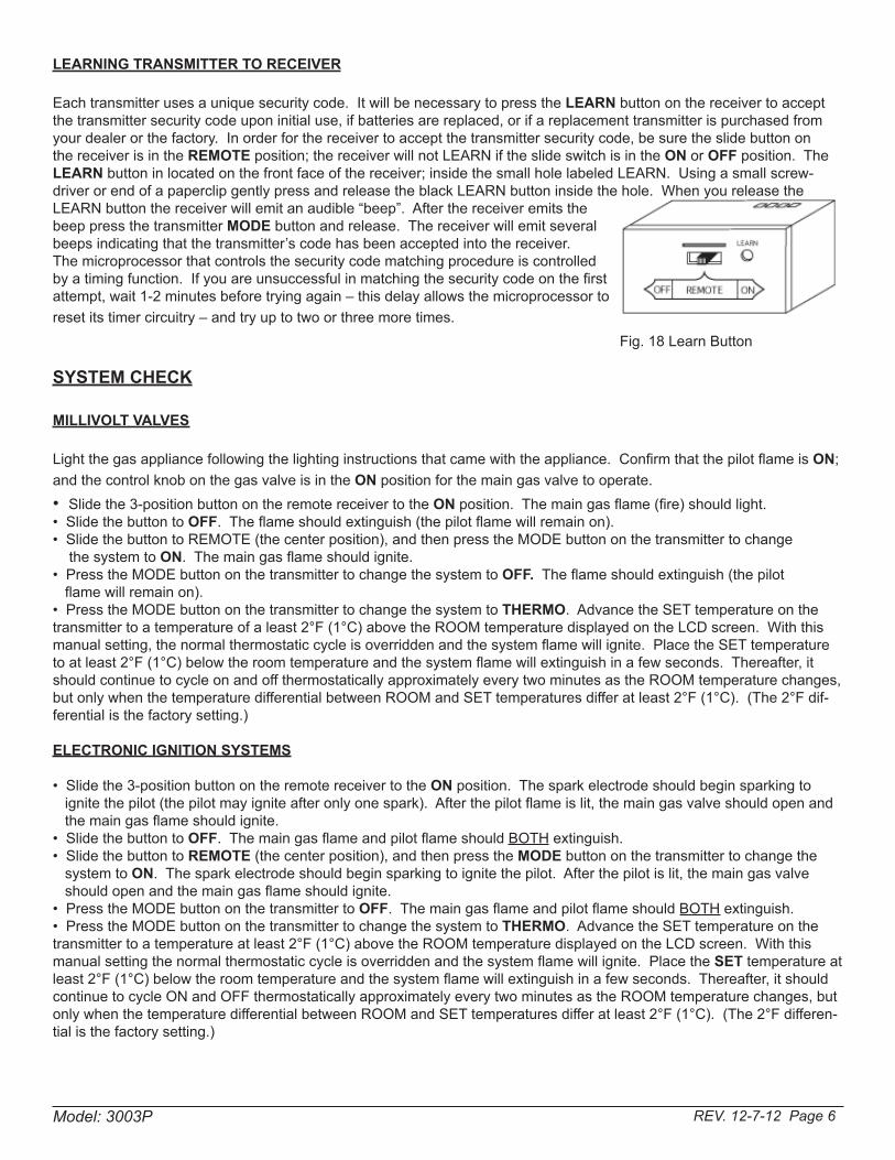
Each transmitter uses a unique security code. It will be necessary to press the LEARN button on the receiver to accept the transmitter security code upon initial use, if batteries are replaced, or if a replacement transmitter is purchased from your dealer or the factory. In order for the receiver to accept the transmitter security code, be sure the slide button on the receiver is in the REMOTE position; the receiver will not LEARN if the slide switch is in the ON or OFF position. The LEARN button in located on the front face of the receiver; inside the small hole labeled LEARN. Using a small screw-driver or end of a paperclip gently press and release the black LEARN button inside the hole. When you release the LEARN button the receiver will emit an audible “beep”. After the receiver emits the beep press the transmitter MODE button and release. The receiver will emit several beeps indicating that the transmitter’s code has been accepted into the receiver.The microprocessor that controls the security code matching procedure is controlled by a timing function. If you are unsuccessful in matching the security code on the first attempt, wait 1-2 minutes before trying again – this delay allows the microprocessor to reset its timer circuitry – and try up to two or three more times.
Fig. 18 Learn Button
• Slide the 3-position button on the remote receiver to the ON position. The main gas flame (fire) should light. • Slide the button to OFF. The flame should extinguish (the pilot flame will remain on).• Slide the button to REMOTE (the center position), and then press the MODE button on the transmitter to change the system to ON. The main gas flame should ignite.• Press the MODE button on the transmitter to change the system to OFF. The flame should extinguish (the pilot flame will remain on).• Press the MODE button on the transmitter to change the system to THERMO. Advance the SET temperature on the transmitter to a temperature of a least 2°F (1°C) above the ROOM temperature displayed on the LCD screen. With this manual setting, the normal thermostatic cycle is overridden and the system flame will ignite. Place the SET temperature to at least 2°F (1°C) below the room temperature and the system flame will extinguish in a few seconds. Thereafter, it should continue to cycle on and off thermostatically approximately every two minutes as the ROOM temperature changes, but only when the temperature differential between ROOM and SET temperatures differ at least 2°F (1°C). (The 2°F dif-ferential is the factory setting.)
ELECTRONIC IGNITION SYSTEMS
• Slide the 3-position button on the remote receiver to the ON position. The spark electrode should begin sparking to ignite the pilot (the pilot may ignite after only one spark). After the pilot flame is lit, the main gas valve should open and the main gas flame should ignite.• Slide the button to OFF. The main gas flame and pilot flame should BOTH extinguish.• Slide the button to REMOTE (the center position), and then press the MODE button on the transmitter to change the system to ON. The spark electrode should begin sparking to ignite the pilot. After the pilot is lit, the main gas valve should open and the main gas flame should ignite. • Press the MODE button on the transmitter to OFF. The main gas flame and pilot flame should BOTH extinguish.• Press the MODE button on the transmitter to change the system to THERMO. Advance the SET temperature on the transmitter to a temperature at least 2°F (1°C) above the ROOM temperature displayed on the LCD screen. With this manual setting the normal thermostatic cycle is overridden and the system flame will ignite. Place the SET temperature at least 2°F (1°C) below the room temperature and the system flame will extinguish in a few seconds. Thereafter, it should continue to cycle ON and OFF thermostatically approximately every two minutes as the ROOM temperature changes, but only when the temperature differential between ROOM and SET temperatures differ at least 2°F (1°C). (The 2°F differen-tial is the factory setting.)
GENERAL INFORMATIONREMOTE RECEIVERThe remote receiver houses the microprocessor that responds to commands from the transmitter to control the system operation. It emits one beep when it receives an ON or OFF command manually, but no beep when cycling ON and OFF automatically in THERMO mode. The remote receiver has a 3-position slide switch for selecting the MODE of operation: ON/REMOTE/OFF
• With the slide switch in the ON position, the system will remain ON “manually” until the slide switch is placed in the OFF or REMOTE position.• With the slide switch in the REMOTE position (centered), the system will only operate if the remote receiver receives commands from the transmitter. • With the slide switch in the OFF position, the system is OFF. • It is suggested that the slide switch be placed in the off position if you will be away from your home for an extended period of time. If the remote receiver is mounted out of children’s reach, placing the slide switch in the OFF position also functions as a safety “lock-out” by both turning the system off and rendering the remote receiver inoperative.
THERMO- SAFETY FEATURE – RECEIVER (T/S –RX)
This remote control has a THERMO-SAFETY feature that is built into the system’s RECEIVER. This feature is tempera-ture- activated and provides an extra margin of safety when the RECEIVER is operating where ambient temperatures exceed 130°F degrees inside the receiver case.
The THERMO-SAFETY feature, in the RECEIVER, operates in the following manner, when the appliance is in operation.
The receiver is thermally protected from extreme heat conditions. Heat can have negative effect on the operation of the receiver’s microprocessors.
For REMOTE RECEIVERS that operate on BATTERY POWER, these heat conditions can cause batteries to discharge when temperatures exceed 115°F. Studies show that alkaline batteries, when exposed to a constant temperature of 115°F, can lose up to 50% of their operating power. When the battery cools down, it will partially recharge itself, but con-stant heating and cooling will reduce the battery’s normal life expectancy.
When the ambient temperature at the THERMISTOR, inside the receiver case, reaches 130°F, the THERMISTOR will automatically shut the appliance down and the RECEIVER will begin emitting a series of 3 “beeps”, every 4 seconds. When the ambient temperature, at the RECEIVER, drops between 120°F and 130°F, the user can reactivate the appliance by pushing the MODE button on the transmitter. The word ON must display on the LCD screen. When the MODE button is pressed to ON, the THERMISTOR “resets” itself and the fireplace will begin operating again. However, the “beep-ing” will continue, if the ambient temperature remains between 120°F and 130°F. This “beeping” alerts the user that the RECEIVER should be repositioned so the ambient temperature drops below 120°F.
When the temperature drops below 120°F, the “beeping” will cease, providing the user has “reset” the THERMISTOR by pushing the MODE button OFF then ON to operate the appliance. Allow sufficient time for the receiver to cool below 120°F, and then press MODE button to stop beeping.TRANSMITTER
OPERATING SAFETY MONITORS: SYSTEMS SHUTDOWN
The remote control operates on RF (radio frequency) signals that are sent by the TRANSMITTER (remote) to the RE-CEIVER that operates the appliance. It is recommended that the TRANSMITTER always be located within the 20-foot operating range, preferably in the same room in which the appliance is located.
THERMO UPDATING FEATURE –TRANSMITTER
This remote control has a THERMO UPDATING Feature built into its software. The THERMO UPDATING Feature oper-ates in the following manner, but only in the THERMO and PROGRAM MODES:
The transmitter normally reads the ROOM temperature every 2 minutes; checking the ROOM temperature against the SET temperature by sending a signal to the receiver.
Model: 3003P REV. 12-7-12 Page 7
COMMUNICATION – SAFETY – TRANSMITTER – (C/S – TX)
This series remote controls have a COMMUNICATION – SAFETY function built into the software. It provides an extra margin of safety when the TRANSMITTER is out of the normal 20-foot operating range of the receiver.The COMMUNICATION – SAFETY feature operates in the following manner for all OPERATING MODES: ON/THERMO/PROGRAM.
At all times and in all OPERATING MODES, the transmitter sends an RF signal every fifteen (15) minutes, to the receiver, indicating that the transmitter is within the normal operating range of 20-feet. Should the receiver NOT receive a transmit-ter signal every 15 minutes, the IC software, in the RECEIVER will begin a 2-HOUR (120-minute) countdown timing func-tion. If during this 2-hour period, the receiver does not receive a signal from the transmitter, the receiver will shut down the fireplace being controlled by the receiver. The RECEIVER will then emit a series of rapid “beeps” for a period of 10 seconds. Then after 10 seconds of rapid beeping, the RECEIVER will continue to emit a single “beep” every 4 seconds until a transmitter signal is again received. The intermittent 4 second beeping will go on for as long as the receiver’s bat-teries last which could be in excess of one year. To “reset” the RECEIVER and operate the fireplace system, you must press the MODE button on the transmitter. The word ON must display on the LCD screen. By turning the system to ON, the COMMUNICATION SAFETY operation is overridden and the system will return to normal operation depending on the MODE selected at the transmitter.The COMMUNICATION SAFETY feature will reactivate should the transmitter be taken out of the normal operating range or should the transmitter’s batteries fail or be removed.
GENERAL INFORMATION
PROGRAM OPERATION OF THE TRANSMITTER
The transmitter has a built-in factory program, (7) days a week with (4) continuous time periods for each day. Each time period has it’s own starting time and temperature. A chart of the built- in programs is at the right. NOTE: The ending time for one period is the starting time for the next period.
You may change any of the factory settings by following the procedures below. Should you desire to return to the factory program, follow the procedures under heading PROGRAM REVIEW or PROGRAM CANCELLATION.
Model: 3003P REV. 12-7-12 Page 8
PROGRAMMING THE TRANSMITTER TO YOUR CUSTOM SETTINGS
The transmitter built-in program is exactly the same for everyday of the week. If desired, you may change a single day or all seven (7) days of the built-in program. Use the blank table on the next page and fill in your customized settings. To change one or all seven days open the transmitter front cover and complete the following steps:
STEP 1: Press the PROG button for 4 seconds and release. The words START and For will begin to blink (Fig. 20). The current DAY, PERIOD, TIME and SET temperature of the built-in factory program will also be displayed.
To program the DAY and PERIOD OF DAY, press the AHEAD or BACK buttons to display the DAY and PERIOD you wish to program. When you have reached the correct DAY and PERIOD OF DAY push the PROG button and the TIME will blink on the LCD screen (Fig. 21).
PERIOD MORN DAY EVE NIGHT TIME TEMP TIME TEMP TIME TEMP TIME TEMP
S (Sunday)
M (Monday)
T (Tuesday)
W (Wednesday)
T (Thursday)
F (Friday)
S (Saturday)
STEP 2: To program the START TIME, press the UP or DOWN buttons to set the hour corresponding with the AM/PM time period. Start time settings are in 15 minutes segments. When desired START TIME is displayed press the PROG button and the SET temperature will blink on the LCD screen.
STEP 3: To program the SET TEMPERATURE, press the UP or DOWN butttons. When desired SET temperature displays, then press the PROG button.
After pressing the PROG button the next PERIOD of the same or next day will display (not blink) on the LCD screen (Fig. 23).
Fig. 21 Setting TIME of Program
Fig. 22. Set Temperature Fig. 23 Period of Day
To program the next Period of Day follow steps 1 through 3 recording them on the blank table below until all (7) days and the (4) time periods in each day are programmed.
Once ALL the programming has been completed, then press the SET button on the transmitter. The programming data you entered will now over-ride the factory built-in program and operate your system.
PROGRAMMING NOTE: Once you are in the programming process, if you only want to program only specific days you can bypass the DAYS and PERIOD of DAY by pushing the AHEAD or BACK buttons. This eliminates the need to enter the TIME and TEMPERA-TURE for specific each DAY and PERIOD speeding up the programming process. Once the LCD screen displays the specific DAY and PERIOD of DAY you want to program press the PROG button and following the steps above.
PROGRAM REVIEWIf you want to review the settings for the FACTORY BUILT-IN program or your customized program, you may do so by pressing the PROG button for one second at a time. To review each setting then press the PROG button one second be-tween each period of day. Press the SET button when finished reviewing to return to normal operation.
PROGRAM CANCELLATIONIf you want to cancel the CUSTOMIZED program you entered and return to the FACTORY program do the following:STEP 1: Press the SET button to ensure the LCD screen is in the normal state.STEP 2: Press and hold the PROG and SET buttons “at the same time” for 10 seconds.STEP 3: The customized programs will be cancelled and the LCD screen will begin blinking the START, FOR, TIME and SET temperature confirming the customized programs have been cancelled.STEP 4: Push the SET button to return the normal LCD screen or wait 10 seconds and it will return automatically.
Fig. 24 Blank table to record custom programming
Model: 3003P REV. 12-7-12 Page 9
AHEAD
TIMER
PROG
TIME
UP
MODE
DOWN
BACK
SET
Model: 3003P REV. 12-7-12 Page 10
CHECKING THERMO OPERATION
The operation of the Thermo setting can be checked on demand by adjusting the SET temperature 2°F above or below the room temperature, which will cause the system to turn ON or OFF, respectively. Normally, however, the system will only respond to temperature changes every two minutes. NOTE: If “SWING” number has been changed, then activation will occur at the new “SWING” setting. See pages 11 and 12 for more temperature SWING information.When the gas fireplace system is activated, a FLAME icon will display on the LCD screen indicating a signal has been sent from the transmitter.
THERMO MODE OPERATION (System operates as a thermostat based on the SET temperature only)
SETTING DESIRED ROOM TEMPERATURE
This remote control system can be thermostatically controlled when the transmitter is in the THERMO mode. 1. To set the DESIRED room temperature, press the MODE button on the transmitter until the word THERMO is visible on the LCD screen. The larger number in the center of the screen is the room temperature and the smaller number on the right side is the SET temperature..2. Press the UP or DOWN button to select the DESIRED room temperature. The highest SET temperature is 99°F (32°C). The lowest SET temperature is 45°F (6°C).3. The TRANSMITTER will monitor the room temperature every 2 minutes automatically turning fireplace ON or OFF thermostatically.
SET TEMPERATURE OVERRIDE – (PROGRAM mode only)
The user may change the current SET temperature without chang-ing the programs stored in the transmitter’s memory. The OVER-RIDE feature will be automatically cancelled at the start of the next PROGRAM PERIOD.
1. To change current SET TEMPERATURE, press the UP or DOWN button (Setting will be cancelled automatically when next program period begins.) The word OVERRIDE will appear over the SET frame on the LCD screen.2. To cancel temperature OVERRIDE, press SET button.
SET TEMPERATURE HOLD – (PROGRAM mode only)
The user may override the SET temperature during any period, adjusting the SET temperature to a CONSTANT new SET/HOLD temperature.
1. Press the UP or DOWN button to change the SET temperature to the level desired. The word OVERRIDE will appear in SET frame on the LCD.2. To HOLD the new temperature at a CONSTANT setting, push the UP and DOWN buttons “at the same time” to activate the HOLD function. The word HOLD will appear over the SET frame and the word OVERRIDE will disappear.3. To cancel OVERRIDE or HOLD, press the SET button.
TRANSMITTER OPERATING MODES
Fig. 25 Thermo on Mode
AHEAD
TIMER
PROG
TIME
UP
MODE
DOWN
BACK
SET
Fig. 26 SET Temperature Override
AHEAD
TIMER
PROG
TIME
UP
MODE
DOWN
BACK
SET
Fig. 27 Set Temperature Hold
AHEAD
TIMER
PROG
TIME
UP
MODE
DOWN
BACK
SET
Model: 3003P REV. 12-7-12 Page 11
TIME OF DAY DISPLAY
1. To check the current TIME of day, press the TIMER/TIME button on the transmitter for less than 1 second. The current TIME of day will appear in the TIME/TEMP frame replacing the temperature reading.2. The TEMPERATURE will reappear in 15 seconds, or you can press the SET button to cancel the display of the time.
SETTING THE COUNTDOWN TIMER
This remote control can operate with the built-in, countdown timer when the transmitter is in the ON or THERMO mode (THERMO or ON must be displayed on the LCD screen). DO NOT operate in PROGRAM MODE, because time is pre-programmed into the transmitter.
1. Press the TIMER/TIME button on the transmitter for more than 2 seconds. The word TIMER and 0:15 flash on the LCD screen.2. Press the UP or DOWN button on the transmitter to begin advancing through each of the countdown time options. Available count down times are 15 min., 30 min, 45 min, 1 hr, 1 hr 30 min, 2 hr, 2 hr 30 min, and each additional half hour up to nine hours.3. To set the TIMER press the SET button on the transmitter. If the system is ON, it will remain on until the “timer” has expired. If the system is in the THERMO mode, it will cancel ON and OFF, as the room temperature requires until the “timer time” has expired. 4. To cancel the TIMER operation, press the TIMER/TIME button for more than 2 seconds.
OPERATIONAL NOTE: When the TIMER is used in the THERMO mode, the THERMO operation will be disabled until the “countdown time” has expired, then normal THERMO mode will presume.
LOW BATTERY INDICATOR
The low battery icon will appear when battery power has dropped significantly. At this time, approximately two weeks of battery power remains until the transmitter may experience partial or complete loss of functions.
NOTE: A reversed battery can activate the LOW battery icon.
Fig. 30 Low Battery Icon
ADDITIONAL PROGRAMMING - OPTIONS TO CHANGE SWING TEMPERATURE
The thermo-transmitter operates the fireplace system whenever the ROOM TEMPERATURE varies a certain number of degrees from the SET TEMPERATURE. This variation is called the “SWING” or TEMPERATURE DIFFERENTIAL. The normal operating cycle of a fireplace system may be 2-4 times per hour depending on how well the room or home is insu-lated from the cold or drafts. A smaller “swing number” increases the number of cycles so the room temperature is more constant. A larger “swing number” decreases the number of cycles, which saves energy, in most cases. The factory set-ting for the “swing number” is 2. This represents a temperature variation of +/- 2°F (1°C) between SET temperature and ROOM temperature which determines when the fireplace will be activate. The “SWING” number values are:1= +/- 1°F (.5°C), 2= +/- 2°F (1°C), 3 = +/-3°F (1.6°C).
Fig. 28 Time of Day
AHEAD
TIMER
PROG
TIME
UP
MODE
DOWN
BACK
SET
Fig. 29 Setting Timer
AHEAD
TIMER
PROG
TIME
UP
MODE
DOWN
BACK
SET
Model: 3003P REV. 12-7-12 Page 12
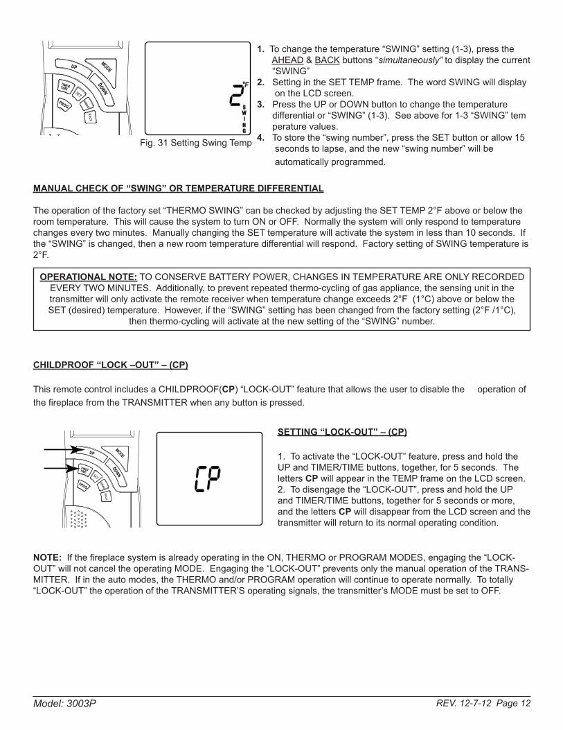
1. To change the temperature “SWING” setting (1-3), press the AHEAD & BACK buttons “simultaneously” to display the current “SWING”2. Setting in the SET TEMP frame. The word SWING will display on the LCD screen.3. Press the UP or DOWN button to change the temperature differential or “SWING” (1-3). See above for 1-3 “SWING” tem perature values. 4. To store the “swing number”, press the SET button or allow 15 seconds to lapse, and the new “swing number” will be automatically programmed.
Fig. 31 Setting Swing Temp
MANUAL CHECK OF “SWING” OR TEMPERATURE DIFFERENTIAL
The operation of the factory set “THERMO SWING” can be checked by adjusting the SET TEMP 2°F above or below the room temperature. This will cause the system to turn ON or OFF. Normally the system will only respond to temperature changes every two minutes. Manually changing the SET temperature will activate the system in less than 10 seconds. If the “SWING” is changed, then a new room temperature differential will respond. Factory setting of SWING temperature is 2°F.
OPERATIONAL NOTE: TO CONSERVE BATTERY POWER, CHANGES IN TEMPERATURE ARE ONLY RECORDED EVERY TWO MINUTES. Additionally, to prevent repeated thermo-cycling of gas appliance, the sensing unit in the transmitter will only activate the remote receiver when temperature change exceeds 2°F (1°C) above or below the SET (desired) temperature. However, if the “SWING” setting has been changed from the factory setting (2°F /1°C),
then thermo-cycling will activate at the new setting of the “SWING” number.
CHILDPROOF “LOCK –OUT” – (CP)
This remote control includes a CHILDPROOF(CP) “LOCK-OUT” feature that allows the user to disable the operation of the fireplace from the TRANSMITTER when any button is pressed.
SETTING “LOCK-OUT” – (CP)
1. To activate the “LOCK-OUT” feature, press and hold the UP and TIMER/TIME buttons, together, for 5 seconds. The letters CP will appear in the TEMP frame on the LCD screen.2. To disengage the “LOCK-OUT”, press and hold the UP and TIMER/TIME buttons, together for 5 seconds or more, and the letters CP will disappear from the LCD screen and the transmitter will return to its normal operating condition.
NOTE: If the fireplace system is already operating in the ON, THERMO or PROGRAM MODES, engaging the “LOCK-OUT” will not cancel the operating MODE. Engaging the “LOCK-OUT” prevents only the manual operation of the TRANS-MITTER. If in the auto modes, the THERMO and/or PROGRAM operation will continue to operate normally. To totally “LOCK-OUT” the operation of the TRANSMITTER’S operating signals, the transmitter’s MODE must be set to OFF.
AHEAD
TIMER
PROG
TIME
UP
MODE
DOWN
BACK
SET
AHEAD
TIMER
PROG
TIME
UPMODE
DOWN
BACK
SET
FCC REQUIREMENTSNOTE: THE MANUFACTURER IS NOT RESPONSIBLE FOR ANY RADIO OR TV INTERFERENCE CAUSED BY UNAUTHORIZED MODIFICATIONS TO THIS EQUIPMENT. SUCH MODIFICATIONS COULD VOID THE USER’S
AUTHORITY TO OPERATE THE EQUIPMENT.
SPECIFICATIONS
BATTERIES: Transmitter 3.0V- 2 ea. AAA 1.5V, Alkaline Remote Receiver 6V – 4ea. AA 1.5 Alkaline FCC ID No.’s: transmitter –K9L3301TX; receiver – K9L301RXOperating Frequency: 303.8MHZ Canadian IC ID No.’s: transmitter – 2439-3301TX; receiver – 2439A-3301RX
Model: 3003P REV. 12-7-12 Page 13
For warranty information please contact the gas appliance supplier for this product.
QUICK SET-UP GUIDEFOR Model 3003P PROGRAMMABLE TRANSMITTER
This guide is a “short cut” method to SETUP and OPERATE the programmable transmitter. For detailed instructions for each feature and function, see OWNER”S MANUAL.
1. SCALE (DEGREE F/ DEGREE C) – Press UP or DOWN button. Press SET button.
2. DAY OF WEEK – Press AHEAD or BACK button. Press SET button.
3. HOUR OF DAY – Press UP or DOWN button. Press SET button. NOTE: AM or PM on LCD.
4. MIN. OF DAY – Press UP or DOWN button. Press SET button.
NOTE: Each SETTING will flash, separately, on LCD screen. After each SETTING you must push SET button. You may not have to change factory setting, but you must push SET button.
All remaining programming wil be made from the front of the transmitter now.
12
34
OPERATION – Press MODE button on TRANSMITTER to change operating functions.
INITIAL SET-UPSET FUNCTIONS USING BUTTONS ON FRONT OFTRANSMITTER
1 2 3 4
1 ON indicates the system is ON, either manually or thermostatically.2 OFF indicates the entire system is turned OFF.3 THERMO indicates the system will automatically cycle ON/OFF thermostatically depending on programmed SET temperature.4 PROG indicates the system is operating with PROGRAM settings.
OTHER OPERATIONS – Press corresponding buttons on TRANSMITTER to activate functions.
TIME OF DAY – Press & release TIMER/TIME button for less than 1-second.
TIME OPERATION – Press and hold TIMER/TIME button for 2-seconds.
COUNTDOWN TIME -- pressing UP or DOWN buttons.
NOTE: Press SET button to stop LCD digits from flashing.
Model: 3003P REV. 12-7-12 Page 13
AHEAD
TIMER
PROG
TIME
UPMODE
DOWN
BACK
SET
AHEAD
TIMER
PROG
TIME
UP
MODE
DOWN
BACK
SET
REV. 12-7-12 Page 14 Model: 3003P
QUICK PROGRAMMABLE GUIDEFOR Model 3003P PROGRAMMABLE TRANSMITTER
This guide is a “short cut” method to SETUP and OPERATE the programmable transmitter. For detailed instructions for each feature and function, see OWNER”S MANUAL.
The transmitter has a built-in factory program, (7) days a week with (4) continuous time periods for each day. Each time period has it’s own starting time and temperature. A chart of the built-in programs is shown below. NOTE: The ending time for one period is the starting time for the next period.
SHORT CUT PROGRAMMING
1. Press PROG button for more than 4-seconds. The words START and FOR on the LCD will begin blinking.2. Program DAY OF WEEK and PERIOD OF DAY by press ing AHEAD and BACK buttons.3. Again, press PROG button. START TIME will begin blink ing. Program START TIME by pressing UP or DOWN button.4. Again, press PROG button. SET TEMP will begin to blink. Program SET TEMP by pressing UP or DOWN buttons. 5. Again, press PROG button. The next DAY OF WEEK and PERIOD OF DAY will begin to blink.6. Repeat steps 2 through 5 for all 7 DAYS until each PERIOD OF DAY is programmed.
When all programmed settings are complete, press the SET to lock in new programs.
To REVIEW, either FACTORY or USER programs, push the PROG button for 1-second; then scroll through each DAY and PERIOD OF DAY by pressing PROG button, allowing 1-second between each press of this button. Press the SET button when finished reviewing the programmed times and temperatures.
To CANCEL user-customized programming, press and hold PROG and SET buttons together, for 10-seconds; all USER programs will be cancelled and the FACTORY program will return.
NOTE: Push AHEAD or BACK buttons to advance day and period should you not want to change each SET time or SET temperature.
PERIOD MORN DAY EVE NIGHT TIME TEMP TIME TEMP TIME TEMP TIME TEMP