Computación y Sistemas Vol. 14 No. 4, 2011 pp 335-350 ISSN 1405-5546 Model Based Testing for Workflow Enabled Applications Pruebas Basadas en Modelos para Aplicaciones Basadas en Workflows Mario E. Sánchez 1 , Camilo H. Jiménez 2 and Jorge A. Villalobos 3 1 Departamento de Ingeniería de Sistemas y Computación, Universidad de los Andes Bogotá, Colombia Software Languages Lab, Vrije Universiteit Brussel Bruselas, Bélgica [email protected]2 Departamento de Ingeniería de Sistemas y Computación, Universidad de los Andes Bogotá, Colombia [email protected]3 Departamento de Ingeniería de Sistemas y Computación, Universidad de los Andes Bogotá, Colombia [email protected]Article received on October 22, 2009; accepted on May 18, 2010 Abstract. In recent years, workflow enabled applications have been used in an increasing number of contexts. This has required the swift development of new workflow languages and of their corresponding engines. However, the tools available to support the development of these engines are insufficient. In particular, the tools to test the implementation of engines have serious limitations, and are not well suited to test workflows. To address this problem we have developed ATF, a framework to build test environments and test suites for workflow engines. ATF is complemented by TDR, a roadmap that specifies the steps to adapt ATF to specific workflow languages and engines; TDR also specifies the steps to develop a complete test suite. This paper presents both the ATF and the TDR, and illustrates their usage in the context of a workflow engine built using the Cumbia platform. Keywords: Model-based Testing, Workflow Testing, Test Scenarios, Trace-based Execution Analysis, Model Driven Engineering, Cumbia. Resumen. La aplicación de la tecnología de los workflows a un gran número de contextos ha traído consigo la necesidad de desarrollar rápidamente nuevos lenguajes de workflow con sus correspondientes motores. Sin embargo, las herramientas para apoyar este desarrollo son insuficientes y en particular lo son las que servirían para probar que los motores implementen correctamente la semántica de los lenguajes. Para enfrentar esta limitación, hemos desarrollado ATF, un framework abstracto para el desarrollo de entornos de prueba y escenarios de prueba para nuevos motores y nuevos lenguajes de workflow. ATF es complementado por TDR, una hoja de ruta que especifica los pasos para construir un nuevo ambiente de pruebas basada en ATF. Este artículo presenta tanto ATF como TDR e ilustra la forma en la que se utilizaron para probar un motor de workflow construido sobre la plataforma Cumbia Palabras clave: Pruebas basadas en modelos, pruebas de workflows, escenarios de prueba, análisis de ejecución basado en trazas, ingeniería basada en modelos, Cumbia. 1 Introduction Workflow enabled applications is a term to describe applications whose functionalities strongly depend on a workflow engine. Very broadly, this means that these applications use workflow modeling languages to describe workflow models, and also that workflow engines are used to instantiate, enact, control, and monitor these workflow models. Nowadays, these applications are gaining more and more popularity because of the benefits they bring, such as flexibility and efficiency gains related to increased control and visibility of business processes. This can be seen in the large number of domains where these applications are used, which include business process management (BPM), complex scientific applications, computer aided design and engineering, and e-learning. In order to use workflows to solve problems in all those different domains it has been necessary to define hundreds of workflow modeling languages. Consequently, engines for enacting those languages have also been developed as well. This trend is not stopping, and new languages and engines continue to be developed every month. Furthermore, it must be considered that workflows are only useful as long as the concepts and structures in the language reflect the concepts
Article received on October 22, 2009; accepted on May 18, 2010
Abstract. In recent years, workflow enabled applications have been used in an increasing number of contexts. This has required the swift development of new workflow languages and of their corresponding engines. However, the tools available to support the development of these engines are insufficient. In particular, the tools to test the implementation of engines have serious limitations, and are not well suited to test workflows. To address this problem we have developed ATF, a framework to build test environments and test suites for workflow engines. ATF is complemented by TDR, a roadmap that specifies the steps to adapt ATF to specific workflow languages and engines; TDR also specifies the steps to develop a complete test suite. This paper presents both the ATF and the TDR, and illustrates their usage in the context of a workflow engine built using the Cumbia platform. Keywords: Model-based Testing, Workflow Testing, Test Scenarios, Trace-based Execution Analysis, Model Driven Engineering, Cumbia. Resumen. La aplicación de la tecnología de los workflows a un gran número de contextos ha traído consigo la necesidad de desarrollar rápidamente nuevos lenguajes de workflow con sus correspondientes motores. Sin embargo, las herramientas para apoyar este desarrollo son insuficientes y en particular lo son las que servirían para probar que los motores implementen correctamente la semántica de los lenguajes. Para enfrentar esta limitación, hemos desarrollado ATF, un framework abstracto para el desarrollo de entornos de prueba y escenarios de prueba para nuevos motores y nuevos lenguajes de workflow. ATF es complementado por TDR, una hoja de ruta que especifica los pasos para construir un nuevo ambiente de pruebas basada en ATF. Este artículo presenta tanto ATF como TDR e ilustra la forma en la que se utilizaron para probar un motor de workflow construido sobre la plataforma Cumbia
Palabras clave: Pruebas basadas en modelos, pruebas de workflows, escenarios de prueba, análisis de ejecución basado en trazas, ingeniería basada en modelos, Cumbia.
1 Introduction
Workflow enabled applications is a term to describe applications whose functionalities strongly depend on a workflow engine. Very broadly, this means that these applications use workflow modeling languages to describe workflow models, and also that workflow engines are used to instantiate, enact, control, and monitor these workflow models. Nowadays, these applications are gaining more and more popularity because of the benefits they bring, such as flexibility and efficiency gains related to increased control and visibility of business processes. This can be seen in the large number of domains where these applications are used, which include business process management (BPM), complex scientific applications, computer aided design and engineering, and e-learning. In order to use workflows to solve problems in all those different domains it has been necessary to define hundreds of workflow modeling languages. Consequently, engines for enacting those languages have also been developed as well. This trend is not stopping, and new languages and engines continue to be developed every month.
Furthermore, it must be considered that workflows are only useful as long as the concepts and structures in the language reflect the concepts
336 Mario E. Sánchez, Camilo H. Jiménez and Jorge A. Villalobos
and structures of the domains. Thus, changes to the domains have a direct impact on the workflow languages. Because of this, workflow enabled applications should be capable of quickly evolving to accommodate new requirements. This makes it necessary for workflow developers to adopt techniques, tools and processes that enable the quick development and modification of languages and engines.
From the point of view of software development, having tools to automatically test workflow engines is an important requirement to support their continuous evolution. This is true for the majority of applications, but in the case of workflows there are two factors that make it even more important. First of all, new versions of a workflow engine are usually required to be backwards compatible, in order to support old workflow models. Thus, automatically performing regression tests is an important concern. Secondly, the development cycles tend to be very short: new features should be implemented and ready to deploy in merely weeks, and it might be impossible to extensively test an entire application without automatized tools.
Automatically testing workflow engines poses interesting requirements and challenges. First of all, it is necessary to have test suites capable of evolving with the workflow languages. This means that changes to the languages or to the engines should not invalidate existing test suites unless it is totally unavoidable. Furthermore, when workflows engines are developed it is critical to assert the consistency between languages semantics and engines implementations. Thus, testing tools should ease these kinds of verifications. Finally, most workflows include constructs to express parallelism and are inherently concurrent. Thus, tools to automatically test workflows should take into account many concurrency-related issues that increase the complexity of test cases. As section 2 shows, existing testing tools are fairly limited in their support for the described requirements.
Cumbia is an advanced platform to build workflow enabled applications based on executable models (18). This platform has been used to develop ad hoc workflow languages like XPM or PaperXpress (19), and also for common workflow languages such as BPEL or BPMN. One important goal of Cumbia is to support the development of workflow languages and engines that are highly extensible. Thus, Cumbia's developers quickly faced the problem of testing the engines and, in particular, testing the conformance of the engines with
language semantics. Their initial approach involved a test framework based on JUnit, but it was too limited and had many problems when dealing with concurrency. A different approach was soon proposed, which was inspired by model-based testing (MBT) and relied on the definition of complementary test languages. This paper presents the results of studying, developing and applying this approach.
The contributions presented in this paper are two. In the first place, it introduces the set of tools developed to test Cumbia-based workflows. These tools are called ATF – Abstract Test Framework, and they are a framework to develop model-based test environments and test suites for specific workflow applications. Throughout the paper ATF is presented and its usage is illustrated by showing how to test the implementation of JCumbia. JCumbia is a Cumbia-based workflow engine that executes processes described using the workflow languages called XPM. Although it was originally developed for Cumbia, the ATF can also be used to test other workflows, provided that they offer the necessary interfaces to query and control their state.
The second contribution of this paper is the TDR- Test Development Roadmap. This roadmap offers guidelines to select, design, and develop test cases for the ATF. It also specifies a set of steps to adapt the ATF to test particular workflow languages and engines.
The paper is structured as follows. Section 2 describes the problems associated to testing workflow engines, and shows how this problem has been tackled in the past and how it can be tackled using an MBT approach. Next, the paper presents the proposed testing approach in detail: section 3 presents the generalities of the strategy and of the ATF; then, section 4 presents the TDR. Finally, the previously presented concepts are illustrated using JCumbia as a case study.
2 Model Based Testing in Workflows
Testing workflow engines in general and, specifically, testing workflow engines to verify its compliance to workflow language semantics, must take into account particular requirements. In the first place, it is not enough to check the outputs of an execution to assert the correctness of the implementation. Instead, it is necessary to verify intermediate results, and the correct execution and interaction of every element involved. Another
Model Based Testing for Workflow Enabled Applications 337
characteristic of workflows is a high degree of concurrency that opens the possibility of having inconsistencies and de-synchronizations caused by invasive testing techniques. In addition, workflow languages and engines tend to evolve and it is thus necessary to have test suites and testing environments that can be grown and evolved easily to accommodate new requirements. Finally, it is critical for workflow engines to support multiple concurrent instances of the processes. Thus, testing environments must support multiple, concurrent instances, and offer capabilities to check that they are correctly isolated.
The general topic of testing workflows can be addressed from two perspectives. In the first place, there has been works on testing workflow models, that is, testing specific processes and verifying their correct structure and execution. These works assume that the engines used to execute the models are properly implemented. Several techniques have been applied to this end, including colored Petri-nets analysis (8), model-checking (2,4) or unit testing (12,16). Some more concrete examples are BPELUnit and the Oracle BPEL Test Framework (5,14): these two tools offer the means to instantiate BPEL processes and provide the necessary stimuli to control their execution.
The second testing perspective is related to testing workflow engines; that is, verifying that the engines do implement the language semantics. Unfortunately, to the best of our knowledge there has been little specific research on this topic. Nevertheless, there are at least two examples of testing workflow implementations that focus on verifying that specific features of the engines are correctly implemented. The first example is an engine executing processes defined using BPEL (17), called Apache ODE
1. As part of this project, a
framework was constructed to automatically run test processes and evaluate their results against some expected values. They already have more than 50 different processes that test features such as flows, if constructions, fault handlers, timers, and others. The downside of this approach is that these are only black-box tests, that rely on final outputs, and that can oversee internal errors. The second example is that of JBoss jBPM
2, which is open-source and
provides a set of JUnit tests. These tests include many aspects of the engine, but they are low level.
1 Apache ODE: http://ode.apache.org
2 JBoss jBPM: http://www.jboss.org/jbossjbpm/
However, it doesn’t show how concurrency issues are dealt, since they use an x-Unit test framework.
Testing of workflow engines is hindered by two characteristics fundamental to workflow applications, namely concurrency and non-determinism. The problem of testing applications with these characteristics has been studied in other contexts, and special attention has been applied to the mechanisms to get relevant information about the execution without creating interference. For instance, it has been argued that in concurrent applications the success of a JUnit test does not imply the validation of the code (3). Because of this, a framework called Concutest -JUnit
3 was developed
to fix problems of the original JUnit implementation. The approach to testing concurrent applications presented Kortenkamp et al. in (11) was an important inspiration for our work. Their work is based on traces, which are captured during the execution of the system and are analyzed offline with respect to formal correctness requirements. On the contrary, works such as Java-MaC (9) and Temporal Rover (18) show that capture and analysis of execution information can happen online using specially instrumented code.
The problem of testing non-deterministic applications has been tackled in works such as (13), (10) and (7). These three works address the problem in the context of multithreaded Java applications, and they put particular attention on the problem of exploring every possible execution path.
Model Based Testing (MBT) is an approach for testing by comparing the behavior and outputs of a system under test (SUT) with the behavior and outputs of a model of the SUT (1). Thus, in a typical MBT scenario there is a model that abstracts the SUT’s intended behavior. Even though the SUT and the model are built on the grounds of the same set of requirements, the model is expected to be simpler than the SUT and leave out details that are not relevant for the tests. With MBT, testing proceeds as
follows (see figure 1). First, a set of test cases is
selected according to certain criteria. Then, a testing infrastructure applies the inputs described in each test case to the SUT and to the model. Note that these inputs (inputs and inputs’ in figure 1) are not exactly the same, because there may be differences in format or level of detail. The last step of the testing procedure compares the outputs produced by the SUT and the outputs produced by the model.
3 Concutest: http://www.concutest.org/
338 Mario E. Sánchez, Camilo H. Jiménez and Jorge A. Villalobos
The result of the comparison is a verdict that states whether the SUT passed the tests, if it failed them, or whether the results were inconclusive (20).
Fig. 1. Model Based Testing
MBT has been applied in many different
contexts using different tools. As a result, different specific techniques have been used in each step, as the taxonomy proposed in (20) shows. In this taxonomy, one variation point is the modeling technique used to abstract the SUT: it may involve different amounts of detail, different paradigms, or different characteristics such as non-determinism. Another variation point is the technique used to build the test cases, which ranges from manual to various automated generative approaches.This is closely related to the criteria used in the selection of test cases, which rely on how they are built.
Based on the aforementioned works, and on the experience with JCumbia, we designed an approach based on MBT to test workflow engines and, in particular, test Cumbia-based workflow engines. This strategy specializes the elements shown in
figure 1 to address specific problems of the workflow context (see figure 2): In the first place, the main requirement of a workflow engine is the semantics of the workflow modeling language. This kind of semantics is usually expressed informally, although a few languages also have formal specifications. For example, BPEL has an informal specification (17) but it has been formalized using pi-calculus (15). The language semantics is the main guideline for the engine’s construction, and it is complemented by other functional and non-functional requirements.
Fig. 2. Testing workflow engines using MBT
Every workflow language has an associated
abstract machine. This abstract machine determines the behavior of any test case execution, although it is not necessarily concretized as a software artifact. In many cases, the role of the abstract machine can be fulfilled by someone that manually calculates and documents the expected behavior of a workflow process. Nevertheless, if a language specification is formalized, the role of the abstract machine can be automatized, for instance with a Petri-nets simulator, or with a pi-calculus interpreter. Moreover, even
Model Based Testing for Workflow Enabled Applications 339
when the language specification is not formally defined, it is possible to write small programs to analyze test cases and produce information about particular aspects of the expected behavior. Note that these programs should be kept as simple as possible, and they shouldn’t match the implementation of the engine (the SUT) in complexity.
In the workflow context, test cases are formed by workflow models (processes) complemented with information such as initial data, stimuli, instantiation information and others. In the implementation of our testing tools, we have strived to keep the definition of test cases as high-level as possible: this facilitates understanding and simplifies maintenance and evolution. Using the information included in a test case, the testing infrastructure controls the execution of a process instance and produces analyzable outputs that include the process’ final results and information about the execution. Finally, a verdict is issued based on a comparison of the expected and the actual behavior of the system. Since workflows are inherently non-deterministic, this comparison has to take into account every possible execution path.
3 Defining and Executing Test Cases in the Abstract Test Framework
The ATF (Abstract Test Framework) is a framework to develop model-based test environments and test suites for workflow based applications. The ATF offers two things to be shared by every environment built using it. Firstly, it specifies the structure of test cases and supplies the basic mechanisms to execute them. Secondly, it specifies a mechanism to analyze the execution of test cases, and provides tools to perform these analyses.
3.1 The structure of a Test Case
Fig. 3. Elements of a Test Case
ATF’s test cases are formed by the five elements shown in figure 3: a set of workflow models, an instantiation schema, an animation program, an observation structure, and an assertion program. Workflow models are the definitions of the processes executed during the test case’s run. Normally, a test case only includes one workflow model, but in some situations it is necessary to have several.
The instantiation schema, describes how to instance each workflow model in the test case and how many instances to create. For instance, the schema may specify that a workflow model has to be instantiated three times in parallel or three times in a sequence.
The third element in a test case is an animation program, written with an animation language. The objective of this program is to control the execution of a workflow considering that it depends on some initial input data and on the behavior of its activities. Input data is easily specified, and in some cases the expected behavior of a test case can be derived entirely from this initial data. On the other side, activities’ behavior depends both on external elements and on its own logic. For instance, the behavior of a workflow that consumes web-services depends on the responses obtained from the services, and on the internal activities of the workflow that process the information or use it to take decisions. Because of this, animation programs include statements to ‘simulate’ responses and signals coming from external systems, and they also include statements to control the behavior of activities.
Part of the complexity of testing workflows lies in the fact that verdicts are not only about the final results of a workflow, but they may also involve intermediate states. To solve this, the strategy used in the ATF involves gathering information during the execution, and analyzing it after the execution has finished. The first part, gathering the information, is achieved with an observation structure that creates traces with execution data. An observation structure describes the elements to monitor the execution of a test case, and also describes how to organize in separated traces the results of the monitoring. To avoid altering the execution, these observation structures should be implemented to be as non-intrusive as possible.
The fifth element in a test case, the assertion program, is used to analyze the data gathered with the observation structure. An assertion program specifies how to derive verdicts about the workflow
340 Mario E. Sánchez, Camilo H. Jiménez and Jorge A. Villalobos
test case execution, using the information contained in traces. Assertion programs depend on data analyzers, which are pieces of code that can assemble high-level information from low-level information contained in traces. Thus, with the help of data analyzers, assertion programs can be high-level, but they depend on low-level execution information.
3.2 Executing a Test Case
Once the elements of a workflow test case have been defined, the test case can be executed in the ATF. The execution of a workflow test case involves four phases illustrated in figure 4.
Firstly, during the instantiation phase, an instantiation schema is used to create workflow model instances. In this phase, observation structures are also created for each instance. Next, in the animation phase the animation program is executed. In this way, the SUT is stimulated and processes can begin their execution. Meanwhile, the observation phase is also initiated. This means that the observation structure starts gathering information about the execution and traces are created with this data. Once processes executions finish, the analysis phase starts and the assertion program is executed. In particular, these programs validate a set of assertions by comparing predefined expected results with the corresponding information gathered in traces. In order to obtain specific information from the traces, data analyzers are used in the assertion programs.
The ATF that we developed includes a basic implementation of every element shown in figure 4, but these implementations must be refined and specialized to be used for specific engines. For this purpose, the ATF defines interfaces and abstract classes for the instantiation schema, animation commands, sensors, tracers, data analyzers, and assertions. The implementation of a workflow test case requires specializations of each of these abstract elements, which are described in the next
subsection. In section 5, a concrete example illustrates how ATF elements can be specialized.
3.3 Elements of the ATF
The ATF defines three main components illustrated in figure 5: TestLoader, TestBehavior and TestRunner. The first of them is responsible for loading the definition of a test case. This doesn’t only involve loading the five elements of a test case, but also elements that are responsible for executing the test case. Currently, this component includes a default implementation that loads this information from a default XML schema. Nevertheless, if a different way to load a test case is needed, the TestLoader exposes interfaces for loading each element, making it customizable for different representations of a test case definition.
Model Based Testing for Workflow Enabled Applications 341
The second component is responsible for implementing the behavior of the elements that are responsible for the test case execution. Since this behavior must be customizable for each workflow engine that uses the ATF, this component does not include a default implementation. On the contrary, it
only exposes interfaces that must be implemented in each case and are used dynamically in the execution of a workflow test case. The first interface that must be implemented is the IInstantiator. Its two main responsibilities are: Initializing the workflow engine, and creating the instances of a given
342 Mario E. Sánchez, Camilo H. Jiménez and Jorge A. Villalobos
workflow model. The information of the workflow model, as well as the information needed by other interfaces, is loaded from the test case definition using the TestLoader. Once the IInstantiator is defined, the IAnimator must be implemented. This interface responsibility is interpreting and executing an animation program. Together with the IAnimator, two interfaces must be implemented at the same time: ITracer and ISensor. Their responsibilities include reacting to events in the animation execution, associating events to traces, and handling traces of those events. Finally, once these interfaces are implemented, the ITest interface must be implemented. This interface is responsible for interpreting and executing the assertion program using a set of data analyzers. These elements are also implementations of an interface within this component and their responsibility is to query information that is gathered in elements that implement the ITracer interface.
Finally, the TestRunner component coordinates the execution of the first two components. First, it executes the TestLoader in order to dynamically load the necessary elements of a workflow test case. Then, it uses these elements to execute the given workflow test case definition.
4 Test Development Roadmap
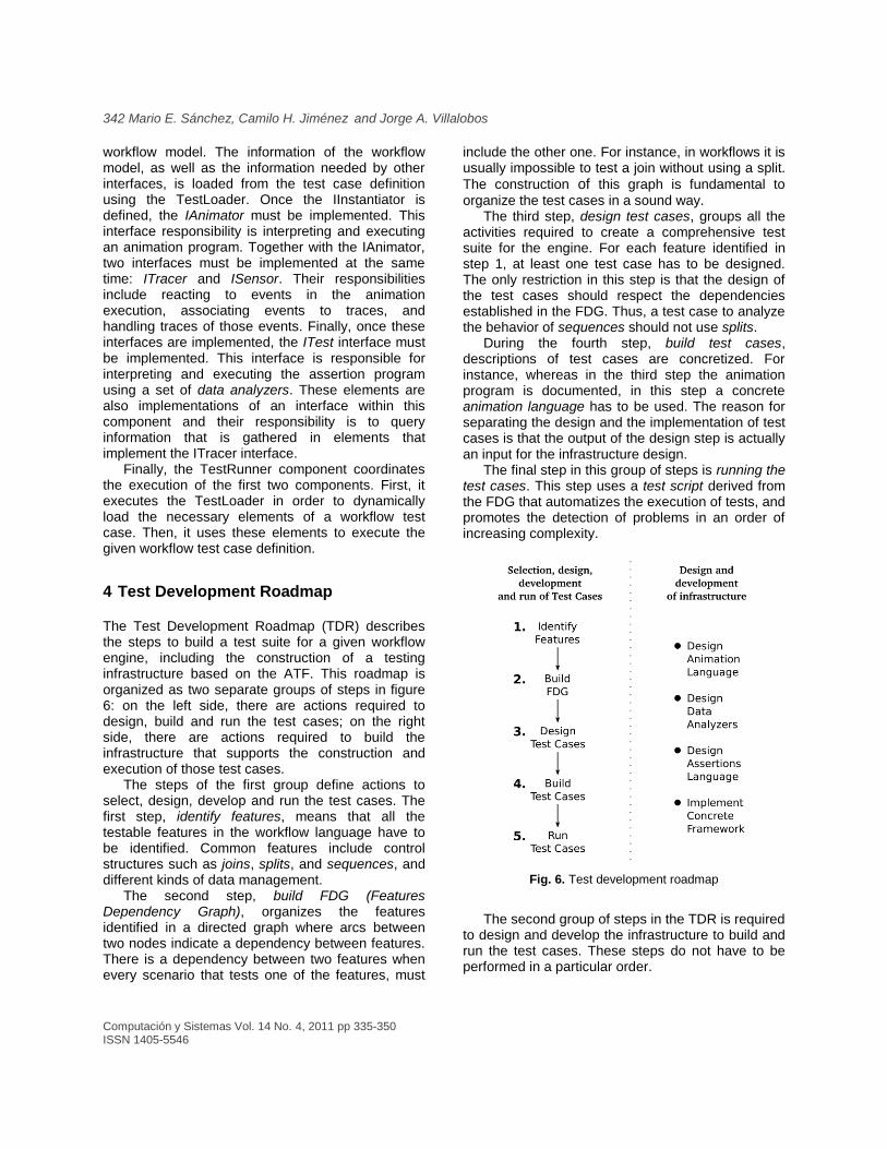
The Test Development Roadmap (TDR) describes the steps to build a test suite for a given workflow engine, including the construction of a testing infrastructure based on the ATF. This roadmap is organized as two separate groups of steps in figure 6: on the left side, there are actions required to design, build and run the test cases; on the right side, there are actions required to build the infrastructure that supports the construction and execution of those test cases.
The steps of the first group define actions to select, design, develop and run the test cases. The first step, identify features, means that all the testable features in the workflow language have to be identified. Common features include control structures such as joins, splits, and sequences, and different kinds of data management.
The second step, build FDG (Features Dependency Graph), organizes the features identified in a directed graph where arcs between two nodes indicate a dependency between features. There is a dependency between two features when every scenario that tests one of the features, must
include the other one. For instance, in workflows it is usually impossible to test a join without using a split.
The construction of this graph is fundamental to
organize the test cases in a sound way. The third step, design test cases, groups all the
activities required to create a comprehensive test suite for the engine. For each feature identified in step 1, at least one test case has to be designed. The only restriction in this step is that the design of the test cases should respect the dependencies established in the FDG. Thus, a test case to analyze the behavior of sequences should not use splits.
During the fourth step, build test cases, descriptions of test cases are concretized. For instance, whereas in the third step the animation program is documented, in this step a concrete animation language has to be used. The reason for separating the design and the implementation of test cases is that the output of the design step is actually an input for the infrastructure design.
The final step in this group of steps is running the test cases. This step uses a test script derived from the FDG that automatizes the execution of tests, and promotes the detection of problems in an order of increasing complexity.
Fig. 6. Test development roadmap
The second group of steps in the TDR is required
to design and develop the infrastructure to build and run the test cases. These steps do not have to be performed in a particular order.
Model Based Testing for Workflow Enabled Applications 343
The ATF showed in section 3 includes elements that can be reused and elements that have to be specialized for each workflow engine. Because of this, the TDR includes three coarse design steps: Design the Animation Language groups the activities required to design the syntax and language semantics used to write animation programs; Design Data Analyzers groups the necessary tasks to define which data analyzers are needed for the test cases, and how each one of them can gather the necessary information; Design Assertions Language groups the activities required to design a language that can be used to write assertion programs.
The final step in the development of the infrastructure is implementing the concrete framework. This step does not include design activities, but only implementation tasks. In this step, components and interfaces are implemented or extended to support the languages designed. This step also includes the implementation of data analyzers.
Although the TDR is mainly intended to be used with new workflow engines, it also identifies issues to consider whenever a workflow modeling language evolves. For instance, when new features are added into a language, the FDG has to be updated, new test cases have to be defined and implemented, and the languages have to grow to accommodate the new requirements. Finally, a new test script can be generated and the updated test cases can be executed once again.
5 Testing JCumbia: a case study for ATF and TDR
5.1 JCumbia: an engine for XPM
Cumbia-XPM (eXtensible Process Metamodel) is a metamodel developed to describe workflow processes. This metamodel is composed by a set of elements that are specializations of open objects (18,19). Open objects are coordination elements composed by an object, called the entity, a state machine, and several actions associated to transitions of the state machine. An entity is just a traditional object with attributes and methods. It provides an attribute-based state to the open object and provides part of its behavior in its methods' implementation. The state machine materializes an abstraction of the life-cycle of the entity, allowing other elements to know its state and react to its
changes. Finally, actions are pieces of behavior associated to transitions of the state machine: when a transition is taken, its actions are executed in a synchronized way.
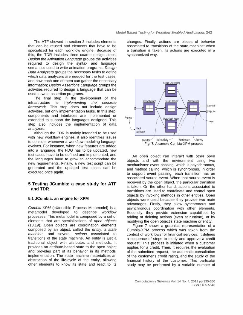
Fig. 7. A sample Cumbia-XPM process
An open object can interact with other open
objects and with the environment using two mechanisms: event passing, which is asynchronous, and method calling, which is synchronous. In order to support event passing, each transition has an associated source event. When that source event is received by the open object, the particular transition is taken. On the other hand, actions associated to transitions are used to coordinate and control open objects by invoking methods in other entities. Open objects were used because they provide two main advantages. Firstly, they allow synchronous and asynchronous coordination with other elements. Secondly, they provide extension capabilities by adding or deleting actions (even at runtime), or by modifying the open object’s state machine or entity.
Figure 7 shows a graphical representation of a Cumbia-XPM process which was taken from the context of workflows for financial services. It defines a sequence of steps to study and approve a credit request. This process is initiated when a customer applies for a credit. Then, it requires the evaluation of the submitted request, the automatic consultation of the customer’s credit rating, and the study of the financial history of the customer. This particular study may be performed by a variable number of
344 Mario E. Sánchez, Camilo H. Jiménez and Jorge A. Villalobos
analysts that depends on the complexity of the customer history. Finally, someone has to approve or reject the request based on the results generated by both studies. This process includes most of the elements defined by the metamodel. It is composed by four activities that are connected through ports and dataflows. Each activity has a distinct workspace and each workspace executes a specific atomic task, Multiactivities are capable of executing several concurrent instances of the same workspace. In summary, activities handle the synchronization and data management for the workspaces. Data flows between activities through the elements of type dataflows. In figure 6 there are 4 activities (Receive Request, Consult Credit Rating, Evaluate Request, and Make Decision), and there is one MultiActivity (Study Credit History). The number of workspaces executed in this MultiActivity is decided at runtime: in the figure, this is specified by the * in the MultiActivity representation.
The Cumbia platform provides the basic support for the execution of open objects, but engines built on top of it provide the precise semantics for each workflow language. JCumbia was developed to execute models built with Cumbia-XPM. JCumbia, and the Cumbia platform, were developed in Java.
The execution of even simple Cumbia-XPM processes can be complex due to the number of state machines that run concurrently, and because of the hundreds of events generated. This complexity created the need for appropriate testing tools to check JCumbia’s implementation and the processes’ execution.
5.2 JCumbia Test Framework
JCumbia Test Framework (JCTF) is the specialization of the ATF to test the JCumbia engine. The JCTF specifically defines what the five elements of a JCumbia test case should be, and provides the implementation of the interfaces to execute them as a test case. We used the default implementation of the TestLoader that the ATF provides.
Workflow Models. In JCTF, workflow models are Cumbia-XPM models, and they are described in the xml-based textual syntax supported by the Cumbia platform. To load these models, the default
implementation of the TestLoader reads the workflow models from files described in an XML tag and keeps a String representation of them.
Instantiation schema. JCTF defines a format to provide instantiation information for JCumbia’s test cases. This information makes references to the definitions of processes, and specifies the number of instances needed for each one. This information also includes some timing information that specifies when to create each instance. In order to support this schema, the IInstanciator interface of the ATF was specialized: this specialization can interpret the instantiation information (loaded by the TestLoader component in a String representation), and it can interact with JCumbia to trigger the creation of the workflow model instances.
Animation Program. JCTF defines a language to write animation programs for Cumbia-XPM test cases. In particular, this animation language provides commands to specify the outputs of each workspace. In this way, it can control the data and the control flow. Other commands in the animation language establish the process inputs and manipulate a process life-cycle in order to test requirements such as persistence. An IAnimator implementation was developed to interpret and execute the commands specified within the animation language. Similarly, the animation program is loaded in a String representation by the default TestLoader implementation.
Observation Structure. JCTF has generic sensors to observe and listen to events generated by any element in a process. Since the elements of a process are open objects, specialized sensors implementing the ISensor interface were developed to listen for events generated by open objects’ state machines. Furthermore, these sensors can be installed dynamically on elements created at runtime. Sensors and open objects provide a flexible observation structure that does not require changes to JCumbia. The placement of sensors is defined with a language illustrated in section 5.3. and it is specified in the default XML test case definition schema parsed by the default TestLoader.
In order to gather information listened by sensors, specialized tracers were implemented, which accumulate different information about the execution. In the next section we will discuss two of them in the context of a particular test case. Specific sensors are associated with tracers using the default XML test case definition schema.
Assertion Language and Data Analyzers. Specialized data analyzers were implemented to query the traces for information such as the following: the last state of an element, the number of times that an activity was executed, the value of the
Model Based Testing for Workflow Enabled Applications 345
data that passes through ports, and the number of times that a transition was taken. The relation between these data analyzers and specific tracers is defined in the default XML test case definition schema. Data analyzers are used by assertion programs, which are defined in a language also illustrated in the next section. These assertion programs are defined and interpreted by specialized interpreters that implement the ITest interface.
5.3 Following the Roadmap
This section describes how we followed the steps defined in the TDR to test JCumbia using the testing infrastructure that was just described and a concrete test case.
Step 1. Identify Features. After analyzing Cumbia-XPM, we identified the features summarized in table 1.
Table 1. Main features of Cumbia-XPM
F1 Basic data and control flow
Basic data and control flow in a process with one activity.
F2 Workspace memory access
Workspaces can read values from their memory.
F3 Data flow with several variables
Data flows can manage several variables.
F4 Dataflow mapping
Mapping of variables’ names.
F5 Sequence control pattern
Sequential activities connected by a dataflow.
F6 XOR-split control pattern
An activity produces data only through one of two exit ports.
F7 Fork-split control pattern
After a given activity, two activities are executed in parallel
F8 Join control pattern
An activity depends on the data produced by two parallel activities
F9 Cycles
Workflow structure with simple cycles
F10 Multiactivity: single output
A multiactivity is deactivated when its first workspace finishes.
F11 Cycles with multiactivities
Cycles in a workflow with multiactivities.
F12 Multiactivity’s dynamic instance creation
Number of workspaces’ instances defined at execution.
F13 Subprocesses
Hierarchical structure of processes.
F14 Arbitrary cycles
Complex cyclic workflow structure.
F15 Workflow Instance (WI) persistence
An instance can be suspended and persisted. It can be reloaded and its execution resumed with no side effects.
F16 WI with subprocesses persistence
An instance containing subprocesses can be suspended and persisted at execution. It can be reloaded and its execution resumed with no side effects.
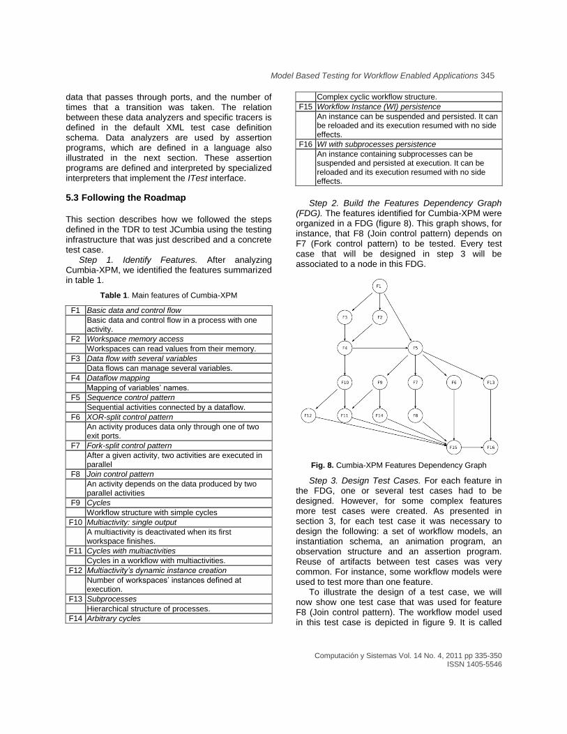
Step 2. Build the Features Dependency Graph
(FDG). The features identified for Cumbia-XPM were organized in a FDG (figure 8). This graph shows, for instance, that F8 (Join control pattern) depends on F7 (Fork control pattern) to be tested. Every test case that will be designed in step 3 will be associated to a node in this FDG.
Fig. 8. Cumbia-XPM Features Dependency Graph
Step 3. Design Test Cases. For each feature in the FDG, one or several test cases had to be designed. However, for some complex features more test cases were created. As presented in section 3, for each test case it was necessary to design the following: a set of workflow models, an instantiation schema, an animation program, an observation structure and an assertion program. Reuse of artifacts between test cases was very common. For instance, some workflow models were used to test more than one feature.
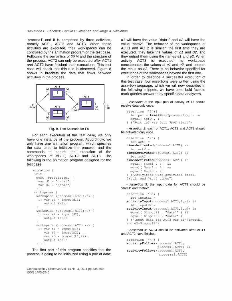
To illustrate the design of a test case, we will now show one test case that was used for feature F8 (Join control pattern). The workflow model used in this test case is depicted in figure 9. It is called
346 Mario E. Sánchez, Camilo H. Jiménez and Jorge A. Villalobos
‘process1’ and it is comprised by three activities, namely ACT1, ACT2 and ACT3. When these activities are executed, their workspaces can be controlled by the animation program of the test case. Following the semantics of XPM and the structure of the process, ACT3 can only be executed after ACT1 and ACT2 have finished their executions. This test case will check that this rule is observed. Figure 8 shows in brackets the data that flows between activities in the process.
Fig. 9. Test Scenario for F8
For each execution of this test case, we only have one instance of the process. Accordingly, we only have one animation program, which specifies the data used to initialize the process, and the commands to control the execution of the workspaces of ACT1, ACT2 and ACT3. The following is the animation program designed for the test case.
animation {
init {
port (process1:pi) {
var d1 = "data1";
var d2 = "data2";
} }
workspaces {
workspace (process1:ACT1:ws) {
1: var e1 = input(d1);
output (e1);
}
workspace (process1:ACT2:ws) {
1: var e2 = input(d2);
output (e2);
}
workspace (process1:ACT3:ws) {
1: var t1 = input(e1);
var t2 = input(e2);
var e3 = concat(t1,t2);
output (e3);
} } }
The first part of this program specifies that the process is going to be initialized using a pair of data:
d1 will have the value “data1" and d2 will have the value “data2". The behavior of the workspaces of ACT1 and ACT2 is similar: the first time they are executed, they take the values of d1 and d2, and they output them using the names e1 and e2. When activity ACT3 is executed, its workspace concatenates the values of e1 and e2, and outputs the result as e3. There is no behavior specified for executions of the workspaces beyond the first one.
In order to describe a successful execution of this test case, four assertions were written using the assertion language, which we will now describe. In the following snippets, we have used bold face to mark queries answered by specific data analyzers.
- Assertion 1: the input port of activity ACT3 should
receive data only once.
assertion ("1"){
let pwf = timesFull(process1.ip3) in
equal( $pfw , 1 )
} ("Port ip3 was full $pwf times")
- Assertion 2: each of ACT1, ACT2 and ACT3 should be activated only once.
assertion ("2") {
let act1 =
timesActivated(process1.ACT1) &&
let act2 =
timesActivated(process1.ACT2) &&
let act3 =
timesActivated(process1.ACT3) in
equal( $act1 , 1 ) &&
equal( $act2 , 1 ) &&
equal( $act3 , 1 )
} ("Activities were activated $act1,
$act2, and $act3 times")
- Assertion 3: the input data for ACT3 should be “data1" and “data2".
assertion ("3") {
let inputE1 =
activityInput(process1.ACT3,1,e1) &&
let inputE2 =
activityInput(process1.ACT3,1,e2) in
equal( $inputE1 , "data1" ) &&
equal( $inputE2 , "data2" )
} ("Input data for ACT3 was e1=$inputE1
and e2=$inputE2")
- Assertion 4: ACT3 should be activated after ACT1
and ACT2 have finished.
assertion ("4") {
activityFollows(process1.ACT3,
process1.ACT1) &&
activityFollows(process1.ACT3,
process1.ACT2)
Model Based Testing for Workflow Enabled Applications 347
The four assertions presented above provide the requirements for the observation structure. The following events and information are relevant to the verification of the assertions: the input port of ACT3 gets full (assertion 1); ACT1, ACT2 and ACT3 are activated (assertion 2); input data received by ACT3 when it is activated (assertion 3); ACT1 and ACT2 are deactivated, and ACT3 is activated (assertion 4). This information can be obtained with sensors that notify about the activation of activities (transition ‘Activate’ in the state machines) and about the reception of data in the port (transition ‘Pack’ in the state machine). The following snippets show the language used to describe the points where sensors have to be installed. Note that wild cards make it possible to use a single expression to describe several sensors.
activity-process1:*-Activate.
These sensors are connected to a SimpleTracer that logs events and the elements that produced them. With these sensors it is possible to verify assertion 2.
port-process1:ACT3:ip3-Pack. This
sensor is connected also to a SimpleTracer that makes it possible to verify assertion 1.
These three sensors are used to verify assertion 4 and they are connected to a SimpleTracer. The third of these sensors is also connected to an ActDataTracer, which logs the data that the activity received when its execution started. The data in the tracers are logged using XML. This way, data analyzers can later query this information in a structured basis.
Finally, the Data Analyzers required for the assertions have to be associated with the corresponding tracers in order to give them access to the information that they need.
Step 4. Build Test Cases. In this step all the elements of a test case are written down and packaged. This includes a descriptor for each test case specifying its components and the feature under test. Using this information, a test script is generated from the FGD. Within a single feature, test cases should not have dependencies; consequently, they can be run in any order.
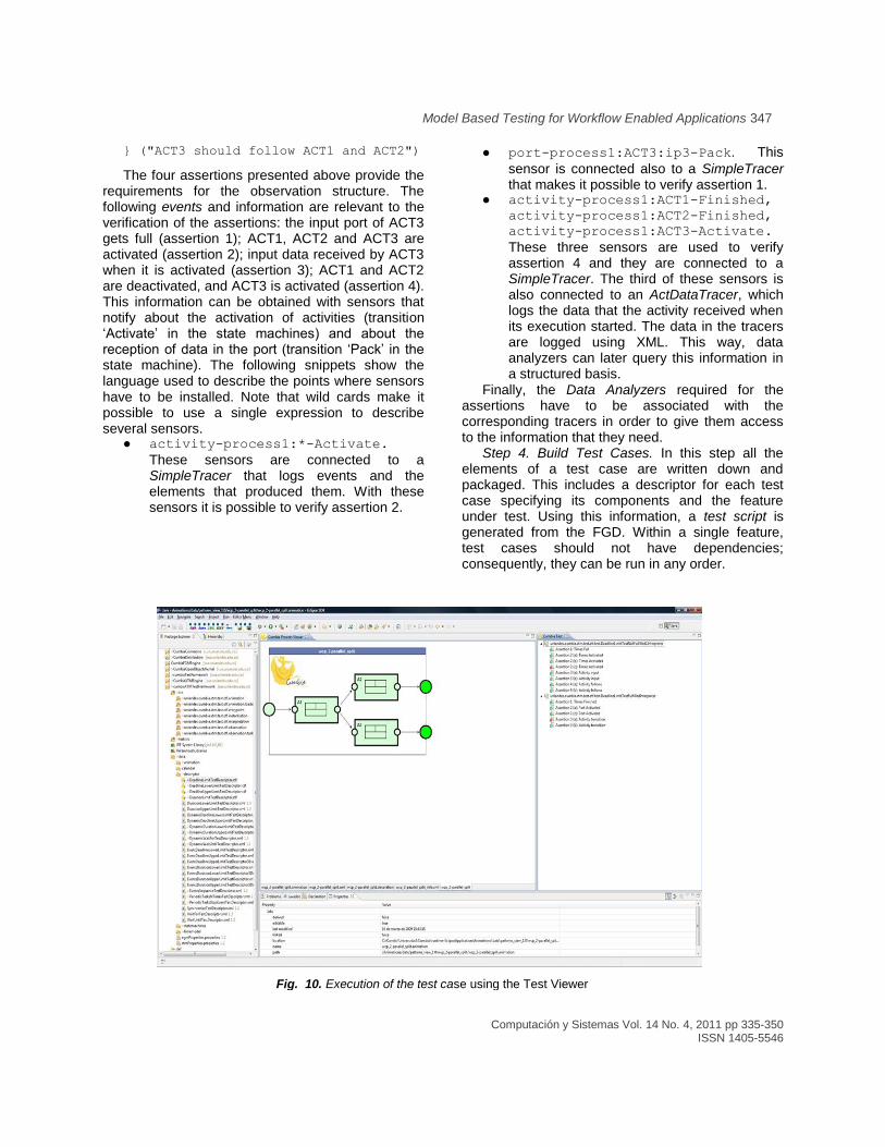
Fig. 10. Execution of the test case using the Test Viewer
348 Mario E. Sánchez, Camilo H. Jiménez and Jorge A. Villalobos
Step 5. Run Test Cases. Our testing infrastructure offers two ways to run the test cases. In the first one, the test script is used to execute automatically all the test cases. The results are informed to the user in a textual way.
The second way to run the test cases is to use a graphical tool that was developed as an Eclipse plug-in. This tool is called the Test Viewer (figure 10) and it presents, in a graphical way, the execution of the test cases and their results. To show the results, this tool uses an eclipse view similar to JUnit where the evaluation of the assertion programs can be easily checked (see CumbiaTest view at the right).
6 Conclusions
In this paper, we analyzed some of the problems associated with testing workflow engines, and we proposed a solution for them in the form of a framework (ATF) and a roadmap (TDR) for the development of tests and adaptations to the framework. In this work, the ideas of Model Based Testing are applied in the specific context of workflow engine testing, and the result was a framework that can be specialized to test specific engines. In the introduction to this paper, we described the two main problems associated to testing workflow engines: the support of concurrency in workflows and the evolution of workflow languages.
With respect to the issue of handling concurrency in the workflows, the testing strategy used by this framework relies on offline analysis. For this, the framework controls continuously the execution of the processes, while obtaining information about the execution that is stored in traces. Finally, the information stored in those traces is analyzed. With respect to the issue of the continuous evolution of the workflow languages, we propose the Test Development Roadmap. On the one hand, this roadmap defines a set of steps to tailor the framework to a particular engine. On the other hand, it defines the steps to develop the test cases. Furthermore, the structure of the framework and the structure of these steps make it possible to adapt everything to the changes in the languages.
This paper illustrated the usage of the ATF and the TDR in the context of JCumbia, an engine for XPM processes built on top of the Cumbia platform. Although ATF and the TDR were initially developed for testing Cumbia-based engines, they can also be applied to many other unrelated engines. However,
we have seen that testing workflow engines requires powerful mechanisms to capture the internal state of the processes. If these observation means are not available, then the analysis of the executions has to rely on the final results of the execution, which can be insufficient.
We are currently working on two directions. The first direction is to apply this solution to test workflow engines for several languages by developing specializations for the ATF. This also includes writing the corresponding test suites. Currently we have developed the specializations to test languages such as BPEL, BPMN and IMS-LD: BPEL is a workflow language that focuses on the interaction and composition of web-services; BPMN is a language to model business processes; and IMS-LD is a language to model learn-flows, which are the specific application of workflows to the e-learning context. In the case of testing BPEL, our specialization of the ATF offers functionalities that are similar to those found in BPELUnit or the Oracle BPEL Test Framework. Furthermore, we have also developed specializations to test other ad hoc workflow languages.
On the other side, we are working on the generation of test cases. This involves two main things: firstly, it is necessary to carefully generate workflow models and animation programs that do not contain structural errors (that is processes that do not have deadlocks and that can always be executed successfully); secondly, it is necessary to have tools to analyze these models and derive useful assertion programs for them. The goal of this work is to have totally generated test cases to complement a set of manually created and selected test cases. The generated test cases are specially intended to involve very big processes to test scalability issues in extreme cases.
Acknowledgments
We would like to thank the rest of the Cumbia team for their work on the project. In particular, we would like to thank Iván Barrero, Sergio Moreno and John Espitia, for their work in test related issues.
Mario Sánchez is supported by the VLIR funded CARAMELOS project (http://ssel.vub.ac.be/caramelos/) and by the Departamento Administrativo de Ciencia, Tecnología e Innovación - Colciencias.
Model Based Testing for Workflow Enabled Applications 349
6. Drusinsky, D. (2000). The Temporal Rover and the ATG
Rover. SPIN Model Checking and Software Verification.
Lecture Notes in Computer Science, 1885, 323–330.
7. Edelstein, O., Farchi, E., Nir, Y., Ratsaby, G. & Ur, S.
(2002). Multithreaded Java program test generation. IBM
Systems Journal, 41(1), 111–125.
8. Gottschalk, F., van der Aalst, W. M. P., Jansen-Vullers,
M. H. & Verbeek, H. M. W. (2007). Protos2cpn: using
colored Petri Nets for configuring and testing business
processes. International Journal on Software Tools for
Technology Transfer, 10(1), 95–110.
9. Kim, M., Viswanathan, M., Kannan, S., Lee, I.,
Sokolsky, O. (2004). Java-mac: A run-time assurance
approach for Java programs. Formal Methods in System
Design, 24(2), 129–155.
10. Konuru, R., Srinivasan, H., & Choi, J.-D. (2000).
Deterministic replay of distributed Java applications. 14th
International Parallel and Distributed Processing
Symposium (IPDPS’00), Cancún, México, 219–227.
11. Kortenkamp, D., Milam, T., Simmons, R. & Lopez, J.
(2001). Collecting and analyzing data from distributed
control programs. Electronic Notes in Theoretical
Computer Science, 55(2), 236-254.
12. Li, Z., Sun, W., Jiang, Z. B. & Zhang, X. (2005).
BPEL4WS unit testing: framework and implementation.
IEEE International Conference on Web Services
(ICWS’05), Orlando, Florida, USA, 103–110.
13. Long, B., Hoffman, D. & Stropper P. (2003). Tool
support for testing concurrent Java components. IEEE
Transactions on Software Engineering, 29(6), 555–566.
14. Lübke, D. (2007). Unit Testing BPEL Compositions. In
Baresi, L. & Di Nitto, E. (Eds.), Test and Analysis of Web
Services (149-171). Berlin; New York: Springer
15. Lucchi R. & Mazzara M. (2007). A pi-calculus based
semantics for WS-BPEL. Journal of Logic and Algebraic
Programming, 70(1), 96–118.
16. Mayer, P., & Lübke, D. (2006). Towards a BPEL unit
testing framework. 2006 workshop on Testing, analysis,
and verification of web services and applications, Portland,
Maine, USA, 33–42.
17. OASIS Technical Committee (2005). Web Services
Business Process Execution Language, Version 2.0.
Retrieved from http://docs.oasis-
open.org/wsbpel/2.0/wsbpel-v2.0.pdf
18. Sánchez, M., Villalobos, J. & Romero, D. (2009). Un
mecanismo de coordinación basado en máquinas de
estado, empleado en las aplicaciones que usan
workflows. Avances en Sistemas e Informática, 6(1), 35–
44.
19. Sánchez, M., Jiménez, C., Villalobos, J. & Deridder D.
(2009). Building a multimodeling framework using
executable models. 47th International Conference on
Objects, Models, Components, Patterns (TOOLS
EUROPE 2009), Zurich, Switzerland, 33, 157-174.
20. Utting, M., Pretschner, A. & Legeard B. (2006). A
Taxonomy of model-based testing (Working Paper:
04/2006). Hamilton, New Zealand: University of Waikato.
Mario E. Sánchez Puccini
Has a M.Sc. in Ingeniería de Sistemas y Computación from the Universidad de los Andes, in Bogotá, Colombia. He is currently enrolled in the doctoral program at the same university and at the Vrije Universiteit Brussel in Belgium. His main areas of research are workflow systems and model driven engineering.
Has a M.Sc. in Ingeniería de Sistemas y Computación from the Universidad de los Andes in Bogotá, Colombia. He currently works as a full time instructor and researcher at the same university. His main areas of research are workflow systems, web interfaces and rich web application development.
Jorge A. Villalobos
Has a Ph.D in Informatics from the University Joseph Fourier in Grenoble, France. He currently is an associated professor at the Universidad de los Andes in Bogotá, Colombia and serves as the chair of the Department of Systems Engineering and Computation. His research focuses in enterprise architectures, BPM and workflows, software architecture, requirements analysis and software design.