COMPOUND YK CENTRIFUGAL LIQUID CHILLER RENEWAL PARTS Supersedes: 160.82-RP1 (513) Form 160.82-RP1 (816) R-134a MODEL CYK CENTRIFUGAL CHILLER / HEAT PUMP SYSTEM WITH QUANTUM™ LX CONTROLS LD15345 Issue Date: August 12, 2016
Transcript
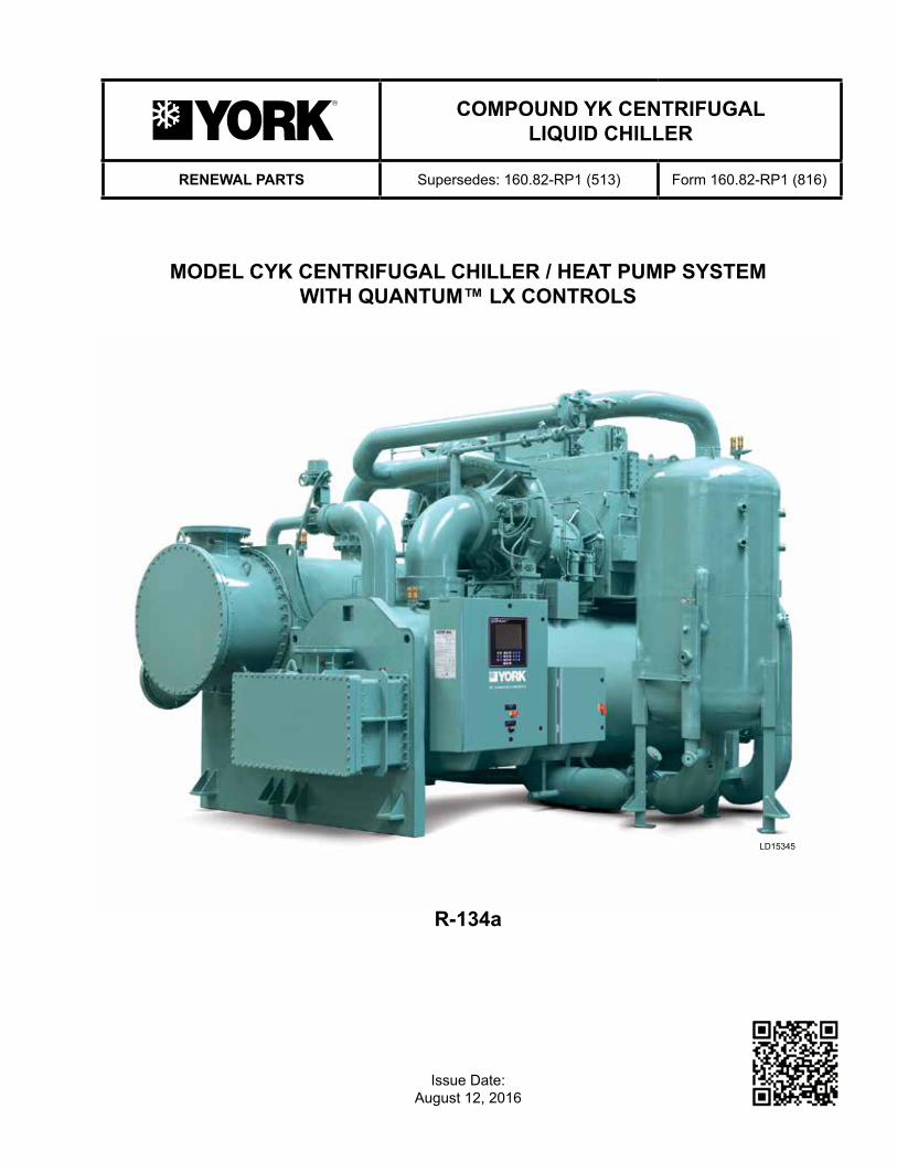
COMPOUND YK CENTRIFUGAL LIQUID CHILLER
RENEWAL PARTS Supersedes: 160.82-RP1 (513) Form 160.82-RP1 (816)
R-134a
MODEL CYK CENTRIFUGAL CHILLER / HEAT PUMP SYSTEM WITH QUANTUM™ LX CONTROLS
LD15345
Issue Date: August 12, 2016
JOHNSON CONTROLS2
This equipment is a relatively complicated apparatus. During installation, operation maintenance or service, individuals may be exposed to certain components or conditions including, but not limited to: refrigerants, materials under pressure, rotating components, and both high and low voltage. Each of these items has the potential, if misused or handled improperly, to cause bodily injury or death. It is the obligation and respon-sibility of operating/service personnel to identify and recognize these inherent hazards, protect themselves, and proceed safely in completing their tasks. Failure to comply with any of these requirements could result in serious damage to the equipment and the property in
IMPORTANT!READ BEFORE PROCEEDING!
GENERAL SAFETY GUIDELINES
which it is situated, as well as severe personal injury or death to themselves and people at the site.
This document is intended for use by owner-authorized operating/service personnel. It is expected that these individuals possess independent training that will en-able them to perform their assigned tasks properly and safely. It is essential that, prior to performing any task on this equipment, this individual shall have read and understood this document and any referenced mate-rials. This individual shall also be familiar with and comply with all applicable governmental standards and regulations pertaining to the task in question.
SAFETY SYMBOLSThe following symbols are used in this document to alert the reader to specific situations:
Indicates a possible hazardous situation which will result in death or serious injury if proper care is not taken.
Indicates a potentially hazardous situa-tion which will result in possible injuries or damage to equipment if proper care is not taken.
Identifies a hazard which could lead to damage to the machine, damage to other equipment and/or environmental pollu-tion if proper care is not taken or instruc-tions and are not followed.
Highlights additional information useful to the technician in completing the work being performed properly.
External wiring, unless specified as an optional connection in the manufacturer’s product line, is not to be connected inside the control cabinet. Devices such as relays, switches, transducers and controls and any external wiring must not be installed inside the micro panel. All wiring must be in accor-dance with Johnson Controls’ published specifications and must be performed only by a qualified electrician. Johnson Controls will NOT be responsible for damage/problems resulting from improper connections to the controls or application of improper control signals. Failure to follow this warn-ing will void the manufacturer’s warranty and cause serious damage to property or personal injury.
FORM 160.82-RP1 ISSUE DATE: 8/12/2016
JOHNSON CONTROLS 3
CHANGEABILITY OF THIS DOCUMENT
In complying with Johnson Controls’ policy for contin-uous product improvement, the information contained in this document is subject to change without notice. Johnson Controls makes no commitment to update or provide current information automatically to the man-ual owner. Updated manuals, if applicable, can be ob-tained by contacting the nearest Johnson Controls Ser-vice office or accessing the Johnson Controls QuickLIT website at http://cgproducts.johnsoncontrols.com.
Operating/service personnel maintain responsibility for the applicability of these documents to the equipment. If there is any question regarding the applicability of
these documents, the technician should verify whether the equipment has been modified and if current litera-ture is available from the owner of the equipment prior to performing any work on the chiller.
CHANGE BARSRevisions made to this document are indicated with a line along the left or right hand column in the area the revision was made. These revisions are to technical in-formation and any other changes in spelling, grammar or formatting are not included.
TABLE 1 - Quantum™ LX Control Panel Components .............................................................................................6
TABLE 2 - VSOP Panel Part Numbers by Voltage .................................................................................................15
TABLE 3 - VSOP Power Panel Parts ......................................................................................................................16
FIGURE 3 - Analog Board Diagram......................................................................................................................... 11
FIGURE 4 - Digital Board #1 ...................................................................................................................................12
FIGURE 5 - Digital Board #2 ...................................................................................................................................13
FIGURE 6 - Time On Delay .....................................................................................................................................14
FIGURE 7 - Power Panel ........................................................................................................................................16
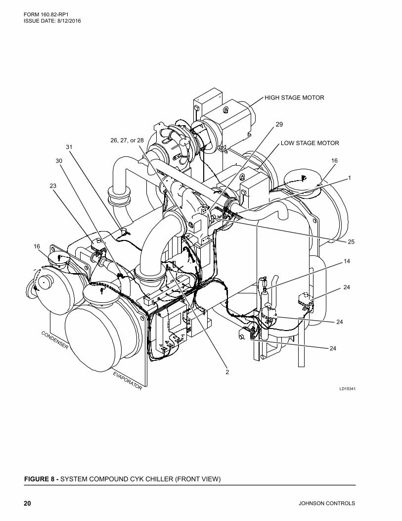
FIGURE 8 - System Compound CYK Chiller (Front View) ......................................................................................20
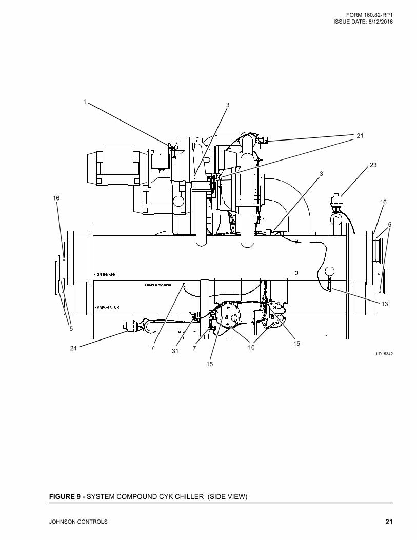
FIGURE 9 - System Compound CYK Chiller (Side View) ......................................................................................21
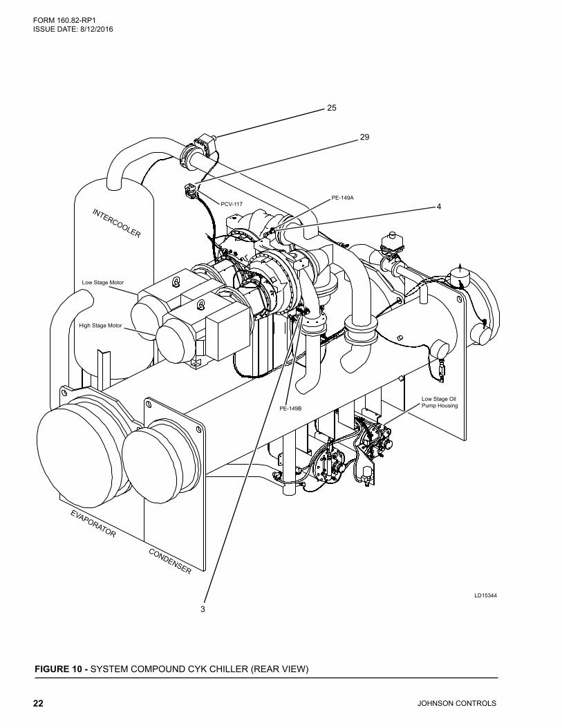
FIGURE 10 - System Compound CYK Chiller (Rear View) .....................................................................................22
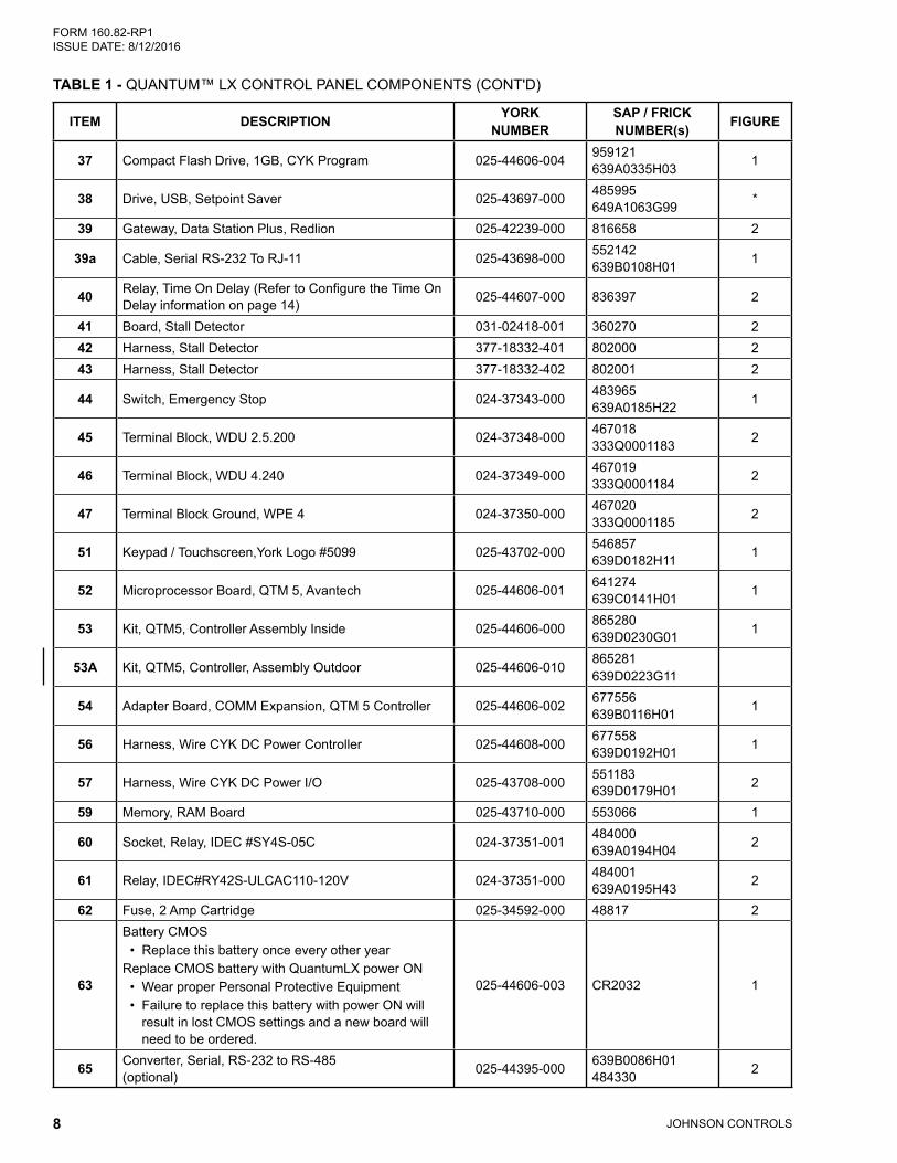
Battery CMOS • Replace this battery once every other yearReplace CMOS battery with QuantumLX power ON • Wear proper Personal Protective Equipment • Failure to replace this battery with power ON will
result in lost CMOS settings and a new board will need to be ordered.
025-44606-003 CR2032 1
65 Converter, Serial, RS-232 to RS-485 (optional) 025-44395-000 639B0086H01
484330 2
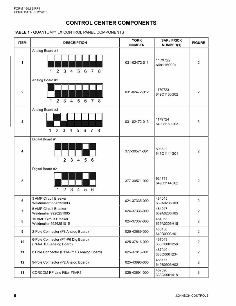
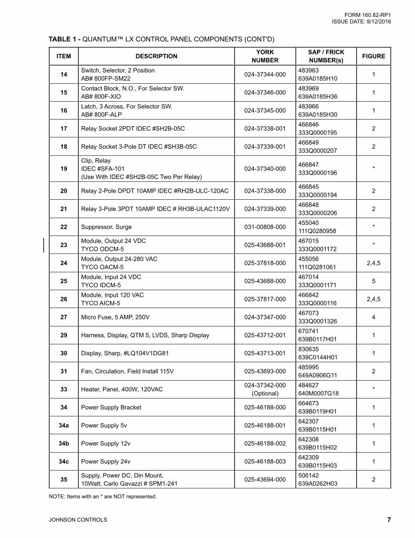
TABLE 1 - QUANTUM™ LX CONTROL PANEL COMPONENTS (CONT'D)
FORM 160.82-RP1 ISSUE DATE: 8/12/2016
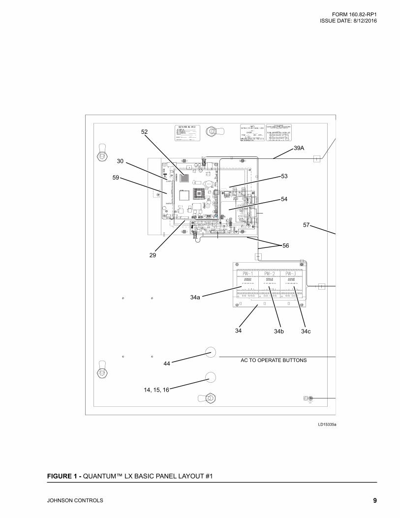
JOHNSON CONTROLS 9
AC TO OPERATE BUTTONS
FIGURE 1 - QUANTUM™ LX BASIC PANEL LAYOUT #1
LD15335a
52
29
34a
34b 34c34
44
14, 15, 16
30
59
39A
53
54
57
56
JOHNSON CONTROLS10
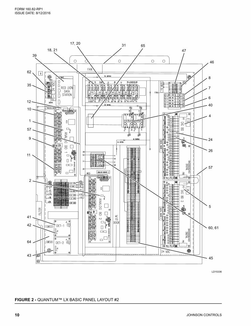
FORM 160.82-RP1 ISSUE DATE: 8/12/2016
FIGURE 2 - QUANTUM™ LX BASIC PANEL LAYOUT #2
LD15336
18, 2139
17, 20 31 6547
46
8
7
6
40
4
26
57
5
45
60, 61
24
62
12
10
1
57
9
11
2
42
64
43
41
35
FORM 160.82-RP1 ISSUE DATE: 8/12/2016
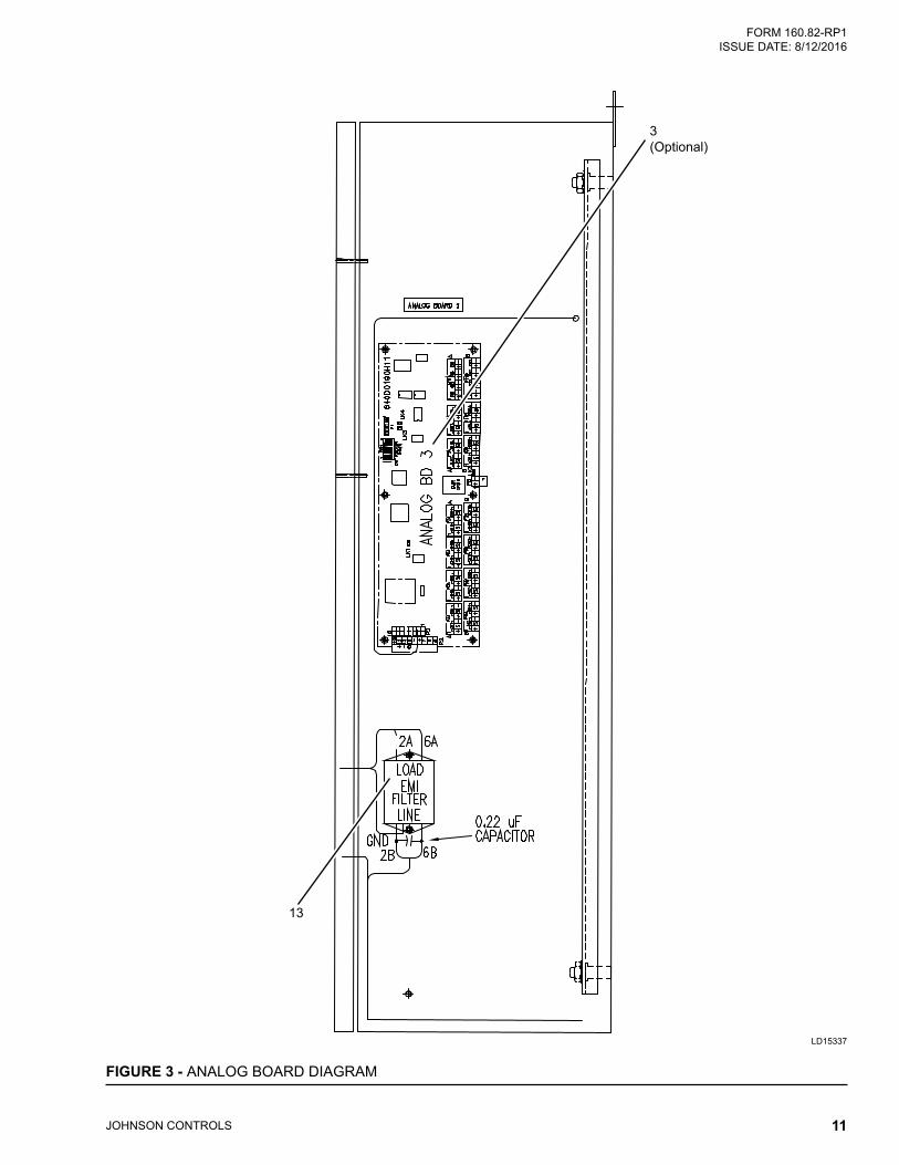
JOHNSON CONTROLS 11
FIGURE 3 - ANALOG BOARD DIAGRAM
LD15337
3(Optional)
13
JOHNSON CONTROLS12
FORM 160.82-RP1 ISSUE DATE: 8/12/2016
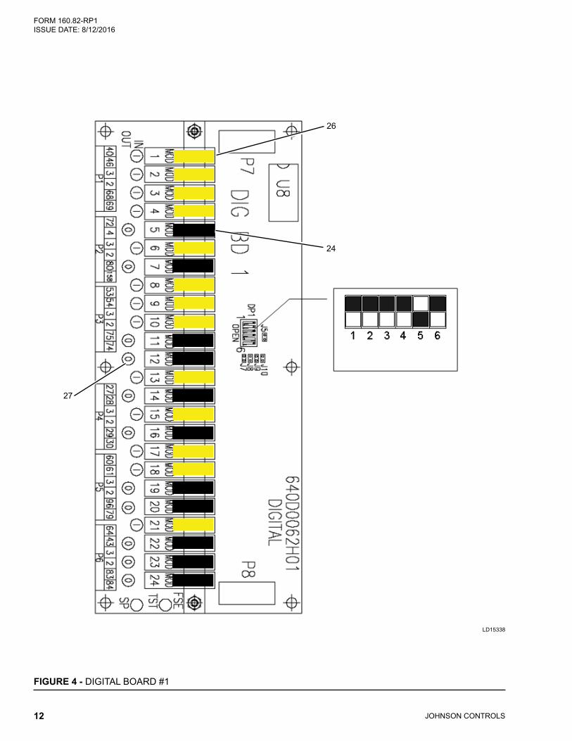
FIGURE 4 - DIGITAL BOARD #1
LD15338
27
26
24
FORM 160.82-RP1 ISSUE DATE: 8/12/2016
JOHNSON CONTROLS 13
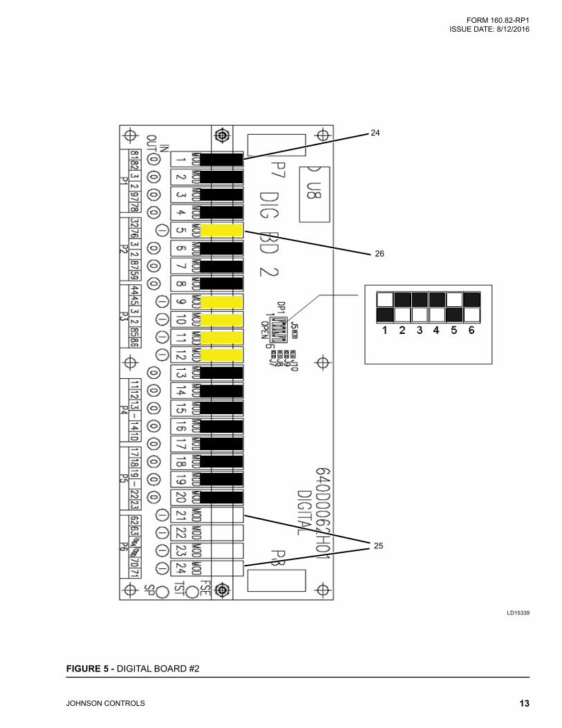
FIGURE 5 - DIGITAL BOARD #2
LD15339
24
26
25
JOHNSON CONTROLS14
FORM 160.82-RP1 ISSUE DATE: 8/12/2016
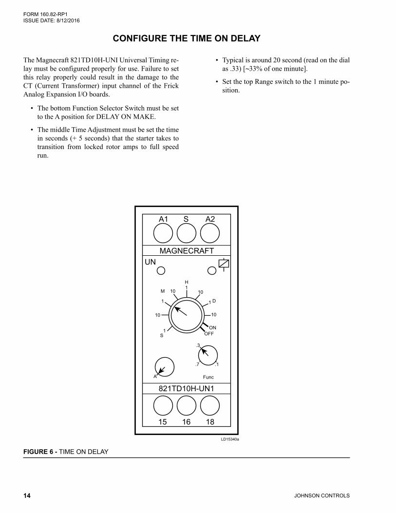
CONFIGURE THE TIME ON DELAY
The Magnecraft 821TD10H-UNI Universal Timing re-lay must be configured properly for use. Failure to set this relay properly could result in the damage to the CT (Current Transformer) input channel of the Frick Analog Expansion I/O boards.
• The bottom Function Selector Switch must be set to the A position for DELAY ON MAKE.
• The middle Time Adjustment must be set the time in seconds (+ 5 seconds) that the starter takes to transition from locked rotor amps to full speed run.
• Typical is around 20 second (read on the dial as .33) [~33% of one minute].
• Set the top Range switch to the 1 minute po-sition.
MAGNECRAFTUN
821TD10H-UN1
1
1
1
1
10
10 10
10
A
.3
.7 .1
OFFON
S
M
H
D
15 16 18
A1 S A2
Func
FIGURE 6 - TIME ON DELAY
LD15340a
FORM 160.82-RP1 ISSUE DATE: 8/12/2016
JOHNSON CONTROLS 15
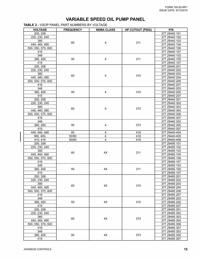
VARIABLE SPEED OIL PUMP PANELTABLE 2 - VSOP PANEL PART NUMBERS BY VOLTAGE
VOLTAGE FREQUENCY NEMA CLASS HP CUTOUT (PSIG) P/N200, 208
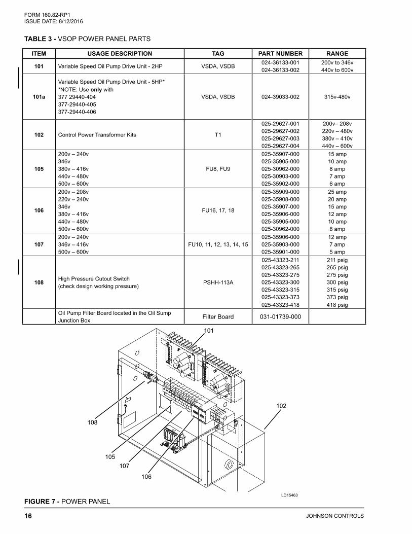
Oil Pump Filter Board located in the Oil Sump Junction Box Filter Board 031-01739-000
LD15463
FIGURE 7 - POWER PANEL
101
108
105107
106
102
FORM 160.82-RP1 ISSUE DATE: 8/12/2016
JOHNSON CONTROLS 17
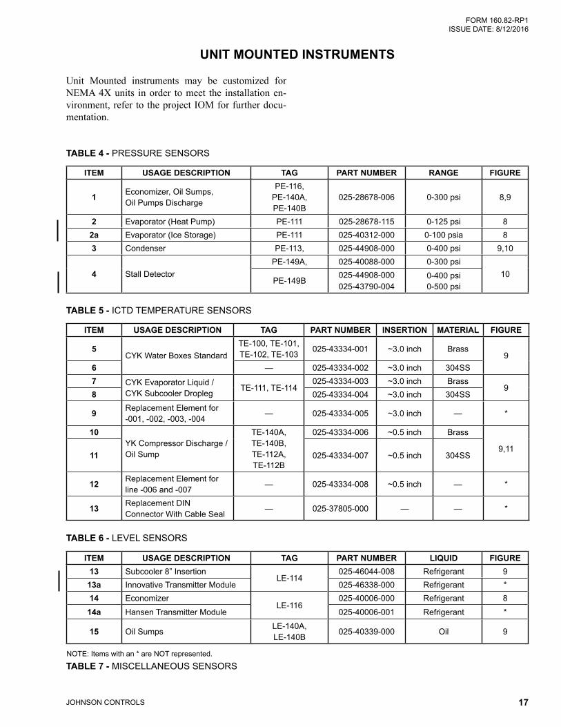
UNIT MOUNTED INSTRUMENTS
Unit Mounted instruments may be customized for NEMA 4X units in order to meet the installation en-vironment, refer to the project IOM for further docu-mentation.
TABLE 4 - PRESSURE SENSORS
ITEM USAGE DESCRIPTION TAG PART NUMBER RANGE FIGURE
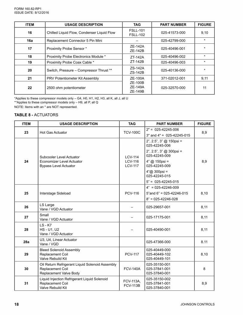
*Applies to these compressor models only – G4, H0, H1, H2, H3, all K, all J, all U**Applies to these compressor models only – H9, all P, all QNOTE: Items with an * are NOT represented.
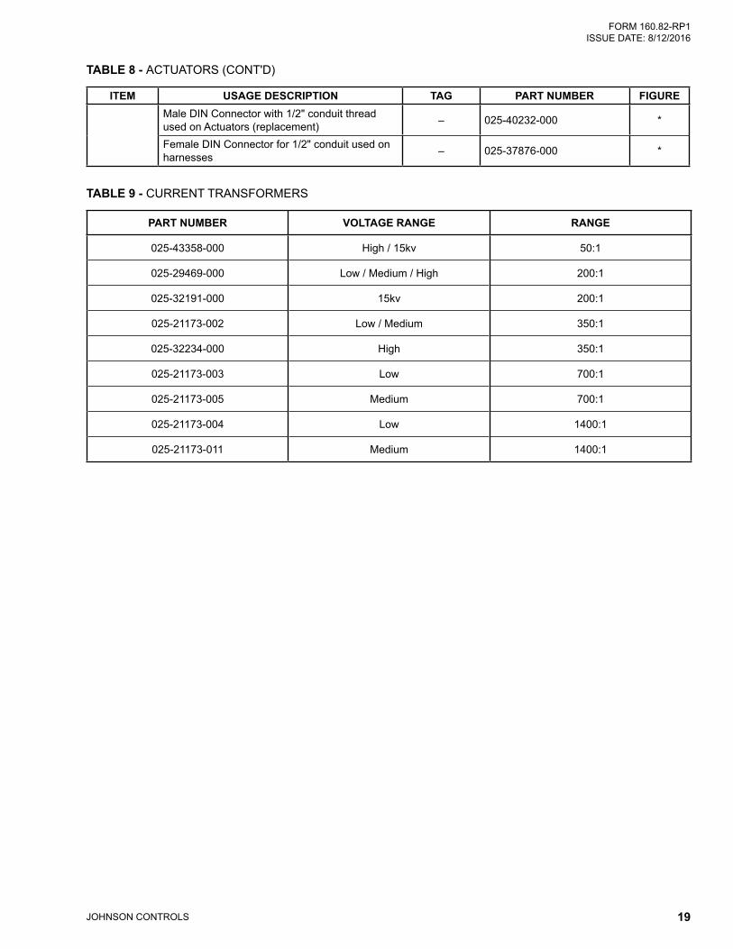
TABLE 8 - ACTUATORS
ITEM USAGE DESCRIPTION TAG PART NUMBER FIGURE
23 Hot Gas Actuator TCV-100C2" = 025-42245-006 3" and 4" = 025-42245-015