MODEL S-100 EYELET BUTTONHOLE MACHINE PARTS AND SERVICE MANUAL MACHINE SERIAL No. PART NUMBER 97. 1700.1.004 AMF is trademark of AMF Group, Inc. 06/ 2013 This manual is valid from the machine serial No.: P174582
Transcript
MODEL S-100
EYELET BUTTONHOLE MACHINE
PARTS AND SERVICE MANUAL
MACHINE SERIAL No.
PART NUMBER 97. 1700.1.004
AMF is trademark of AMF Group, Inc. 06/ 2013
This manual is valid from the machine serial No.: P174582
Warranty Registration Card (Please Fax or Mail immediately after installation)
Note: All Warranty Claims V oid, unless Registration Card on file at AMF Reece HQ
Machine model number:(S100, S101, S104, S105, S 311, Deco, S4000 , EBS Mark II, ES505, etc)
Manufacturer‘s serial or production number:
Installation Site Information:
Customer‘s Name:
Customer‘s Mailing Address:
Customer‘s Telephone Number:
Supervising Mechanic‘s or Technician‘s Name:
Signature of Supervising Technician:
AMF Reece Technician‘s Name:
AMF Reece Technician‘s Signature:
Type of garment produced at this location?
Average Daily Production Expected from this machine?(number of buttonholes, jackets sewn, pants produced, buttons sewn, etc)
Any special requirements required at this location?
What other AMF Reece Machines are at this location?
A ninety (90) day limited service labor warranty to correct defects in installation, workmanship, or material without charge forlabor. This portion of the warranty applies to machines sold as ”installed” only.
A one (1) year limited material warranty on major component parts to replace materials with defects. Any new part believeddefective must be returned freight prepaid to AMF Reece, Inc. for inspection. If, upon inspection, the part or material is deter-mined to be defective, AMF Reece, Inc. will replace it without charge to the customer for parts or material.
Service labor warranty period shall begin on the completed installation date. Material warranty shall begin on the date theequipment is shipped from AMF Reece, Inc.
Exclusions:
Excluded from both service labor warranty and material warranty are: (1) Consumable parts which would be normally consideredreplaceable in day-to-day operations. These include parts such as needles, knives, loopers and spreaders. (2) Normal adjustmentand routine maintenance. This is the sole responsibility of the customer. (3) Cleaning and lubrication of equipment. (4) Partsfound to be altered, broken or damaged due to neglect or improper installation or application. (5) Damage caused by the use ofnon-Genuine AMF Reece parts. (6) Shipping or delivery charges.
There is no service labor warranty for machines sold as ”uninstalled”.
Equipment installed without the assistance of a certified technician (either an AMF Reece Employee, a Certified Contractor, orthat of an Authorized Distributor) will have the limited material warranty only. Only the defective material will be covered. Anycharges associated with the use of an AMF Reece Technician or that of a Distributor to replace the defective part will be thecustomer’s responsibility.
NO OTHER WARRANTY, EXPRESS OR IMPLIED, AS TO DESCRIPTION, QUALITY, MERCHANTABILITY, and FITNESS FORA PARTICULAR PURPOSE, OR ANY OTHER MATTER IS GIVEN BY SELLER OR SELLER’S AGENT IN CONNECTION HERE-WITH. UNDER NO CIRCUMSTANCES SHALL SELLER OR SELLER’S AGENT BE LIABLE FOR LOSS OF PROFITS OR ANYOTHER DIRECT OR INDIRECT COSTS, EXPENSES, LOSSES OR DAMAGES ARISING OUT OF DEFECTS IN OR FAILURE OFTHE EQUIPMENT OR ANY PART THEREOF.
WHAT TO DO IF THERE IS A QUESTION REGARDING WARRANTY
If a machine is purchased through an authorized AMF Reece, Inc. distributor, warranty questions should be first directed to thatdistributor. However, the satisfaction and goodwill of our customers are of primary concern to AMF Reece, Inc. In the event thata warranty matter is not handled to your satisfaction, please contact the appropriate AMF Reece office:
1-9Revised 10/2005e - mail service @amfreece.cz, parts @amfreece.cz, website: www.amfreece.comPhones: +420 582 309 146 (service), +420 582 309 286 (spare parts), Fax +420 582 360 606
A-INTRODUCTION1. Introduction .......................................................................................................................... 1-12. Specifications ........................................................................................................................ 1-23. Safety of work ...................................................................................................................... 1-34. Security of the operator and maintenance ............................................................................... 1-45. List of the safety labels and devices ....................................................................................... 1-66. Position of the labels and the safety devices ........................................................................... 1-7
B - MACHINE INSTALLATION1. Content of the shipping box ................................................................................................... 1-82. Accessories. ......................................................................................................................... 1-83. Machine unpacking and assembling ....................................................................................... 1-94. Adjustment of the T - Belt tension for sewing ......................................................................... 1-125. Adjustment of the left T - belt tension ..................................................................................... 1-136. Thread stand installation. ....................................................................................................... 1-14
C - OPERATOR INSTRUCTIONS1. Preparing to Sew .................................................................................................................. 1-152. Needle Installation ................................................................................................................ 1-163. Threading ............................................................................................................................. 1-16
D - MACHINE ADJUSTMENTS1. Stitches density adjustment .................................................................................................... 1-192. Adjustment of the stitches density in the eye ........................................................................... 1-223. Adjustment of the stitches density in cross bar ........................................................................ 1-224. Lengths of the sewing ............................................................................................................ 1-235. Change of the buttonhole shape - change of the lateral cam .................................................... 1-246. Change of the width bite ........................................................................................................ 1-257. Principles of sewing ............................................................................................................... 1-288. Bed plate alignment ............................................................................................................... 1-349. Testing the cam position ........................................................................................................ 1-3410. Turning mechanism .............................................................................................................. 1-3511. Stopping mechanism ............................................................................................................ 1-3712. Setting - up the mechanism for fabric clamping ..................................................................... 1-3913. Clamp plate spreading ......................................................................................................... 1-4014. Length setting - up of the second buttonhole row ................................................................. 1-4115. Eye shape control ............................................................................................................... 1-4116. Needle bar height ................................................................................................................ 1-4217. Clearance Between the Looper and the Needle ................................................................... 1-4318. Spreaders adjustment .......................................................................................................... 1-4419. Loopers movement ............................................................................................................. 1-45
TABLE OF CONTENTS
1-10
S100
Revised 10/ 2005e - mail service @amfreece.cz, parts @amf reece.cz,website: www.amfreece.com
20. Setting - up of the spreaders movement ............................................................................... 1-4821. Cutting lever and anvil ......................................................................................................... 1-4922. Knife and Cutting Steel change ............................................................................................ 1-5023. Cutting space modification ................................................................................................... 1-5224. Cut Before and Cut After .................................................................................................... 1-5325. Knife adjustment for upper thread trim ................................................................................. 1-5426. Thread draw off mechanism ................................................................................................ 1-56
E - ROUND EYE ADJUSTMENTS1. Introduction .......................................................................................................................... 1-572. Different position of the machine mechanisms ......................................................................... 1-573. Stop motion control .............................................................................................................. 1-584. Round Eye Machine Eyelet Diameter or Cutting Space Change .............................................. 1-595. Clamp feet using for correct buttonhole sewing ...................................................................... 1-596. Adjustment of the supplied accessories .................................................................................. 1-60
F - MACHINE ADJUSTMENT - CROSS BAR1. Introduction. ......................................................................................................................... 1-612. Different position of the machine mechanisms ......................................................................... 1-613. Cross bar relationship to the first and second row of the stitches ............................................. 1-614. Device for sewing the cross bar ............................................................................................. 1-625. Readjustment of the cross bar machine to machine without bar ............................................... 1-646. Readjustment of the cross bar machine to the fly bar machine ................................................. 1-647. Hand feeding ........................................................................................................................ 1-648. Cross bar length adjustment ................................................................................................. 1-659. Correction of the cross bar position in axis X ......................................................................... 1-6610. Cam assembly installation .................................................................................................... 1-6611. Change of the machine rotation ............................................................................................ 1-67
G - MACHINE MAINTENANCE1. Cleaning and maintenance the machine ................................................................................... 1-682. Periodic maintenance ............................................................................................................ 1-693. Machine lubrication ............................................................................................................... 1-704. Machine disposal .................................................................................................................. 1-71
H - DOCUMENTATION1. Electrical diagrams ................................................................................................................ 1-72
The S100-030/031/032 (AF-CB/CA-RE) is a versatile two thread chain stitch sewing machine forsewing buttonholes with possibility to insert the gimp. The regular eye, Cut Before / Cut After, adjustableflybar machine may be used for suits, jeans and a wide variety of sewing applications.
The S 100-052/053 (RE) is two threads, pertinently one thread machine, which is sewing round chainstitch buttonhole. It is used for sewing decorative buttonholes, for example on the hoods or hats.
The S 100-060 (CRB) is two threads machine with chain stitch and opportunity insert the gimp forsewing buttonholes with cross bar and flybar. It allows sewing by one chain thread stitch, which is suitablefor smaller highlighting of the stitches above the fabric (smaller plasticity).
The size of the buttonhole (with eye or without eye) and type of the buttonhole end (open end, flybar orcross bar) are ensured by changeable cams.The semiautomatic lubrication system uses drip oil wicks to lubricate the critical machine areas.To prevent machine damage, it is possible to check the level of oil in the visibly placed oil sight gauge .
Machine models:
S100 - 030 /031/032 AF-CB/CA-RES100 - 030 for standard sewingS100 - 031 for jeans sewingS100 - 032 for textilie sewingS100 - 052 RE (Small eye)S100 - 053 RE (Large eye)S100 - 060 CRB
3 . I N S T R U C T I O N F O R S A F E T Y O F W O R K
The sewing machine S -100 is designed and produced to be highly reliable. Special attention is given forsecuring of the service simplicity and effective safety protection of the operators and machine maintenance.
The machine S -100 has safety appliance which protects operator but also machine and respects validsafety and hygienic rules for usual technological using of the machine. These safety appliances include plugof supply, operating switch (circuit breaker) and covers.
There are safety labels placed on the machine for warning for supplementary danger. Do not remove anddamage these labels. When the label is damaged, order the new one. The said precautions can not cover allsafety aspects that is why operator before using of the machine has to read and understand to this instruc-tions. The mistakes will be eliminated during machine installation and during its own operation. Do not tryto put the machine into operation without reading all the machine instructions and until well understanding toevery function and progress.
There are three types of safety direction in these instructions:
D A N G E R ! Possible loss of life.
WA R N I N G ! Possible serious injury or machine damage.
N O T I C E ! Possible injury or machine damage.
It is recommended to service workers from AMF Reece oversaw to the installation and initial training ofmechanics and operators.Strictly given safety program, which part is the direction for safety operation, is the most effective security ofthe workers safety during the operating with the machine. The secure work with the machine is ensured bythe safety covers which are useful, if they are mounted and fixed correctly. The warning labels and servicemust be done according to the instructions. Operators and service workers should wear safety goggles.
4 . I N S T R U C T I O N S F O R T H E S E C U R I T Y O F T H E O P E R ATO R A N DM A I N T E N A N C E
When the machine is set to the working area, it is recommended to keep the minimal distance said in thedrawing.
D A N G E R !- Before machine connection to the power make sure, whether all safety covers are mounted.- If it is necessary to remove some safety covers, switch off the operating switch (circuit breaker) and
disconnect the machine by the fork of supply from the socket.- Do not connect the machine to the power if some cover is removed.
WA R N I N G !- Remember the position of the operating switch (circuit breaker) so that is possible use it from the
arbitrary position.- Make sure, whether supply of energy and its dimensioning and safeguarding allows permanent
supply of energy needed for dependable output of the machine.- Do not forget to persuade yourself before fork connection to the socket whether both switches on
the machine are switched off.- Check if the electrical cables are not damaged, so that be touch with uncovered conductor, can not
occur any injury.- Check regularly if the safety covers are correctly mounted and whether they are not damaged.- When the covers are demaged, repair or replace them immediately for the new ones.- Do not switch the machine on without covers.- Do not touch rotary shafts by hands.- In any circumstance, do not put hands to the needle space.
- Before changing the needle, switch off the operating switch (circuit breaker).- In case when the operator will not work on the machine, disconnect the power supply by removing
the plug from the socket.- Before cleaning or any maintenance work on the machine, disconnect the power supply by removing
the plug from the socket.- Do not adjust the machine in any way, which could endanger its safety.- Every part of the machine can be dangerous, if there is incorrect manipulation or faulty
maintenance with the machine That is why everybody, who will manipulate, maintain or operatewith this machine must be acquainted with informations included in this manual.
C A U T I O N !- Perform all regular service as described by this manual.- If there is any problem with power supply, turn off the mine power switch (circuit breaker).- Do not remove, paint over, damage or any way change safety labels. If a safety labels are lost or
cannot be easily read, order the new one in our factory and place them on the original place.- Long hair and loose clothing may be dangerous near any machinery. Always contain long hair and
avoid loose clothing, so that it cannot be caught by machinery and cause injury.- Never use this machine while under the influence of drugs or alcohol.- If anything seems to be operating incorrectly in the machine call for maintenance assistance
immediately.- Be sure that there is adequate light for safe operation. A normal minimum light level is 750 Lux.
5 . L I S T O F T H E S A F E T Y L A B E L S A N D D E V I C E S
0.45 - 0.50 MPa
Standard label.Marking of the air pressure (just for S 100 - 033, S 100 - 035 and S 100 - 036).Rotational direction (located on the right cover, left side of the rear cover, motor).Warning by the cover removing (front cover of the frame, right cover of the drive, rear folding cover,motor cover).Label of the safety conductor clip.Necessity of the safety goggles using (sewing head front part, above the needle).External covers of the machine folding or dismantling by the tools.Guard of the upper end of the needle bar.Fixed guard of the needle area.Folding transparent eye guard - in front of the needle area.Axis of the tilting head located irregularly to the driving axis. This solution ensure withdrawing of thebelts from the driving pulleys for lifting of the head for cleaning and maintenance work . When themotor is switched on, the mechanisms of the sewing head will not move.Folding front cover, which precludes the fingers inserting between the moving working board and thefixed frame.
6 . P O S I T I O N O F T H E L A B E L S A N D T H E S A F E T Y D E V I C E S
WA R N I N G ! When the machine works, it is not disabled to give the fingers to the space between themachine table and machine head in marked place. When the working board moves, the clearance in thisplace is about 50 mm. If fingers are accidentally put into this place, it can occur very serious injury.
Front cover of the frame and lock screw of the folding rear cover, which disable tilting of the rear cover, aredismantled during transport. It is necessary to install these safety parts to the machine before the machine isswitched on.
C A U T I O N ! If it is necessary to lift the head out of the home position, it is necessary to tilt the foldingfront cover to the operator side, then put the head back. If this process is not kept, and the machine isswitched on, the cover will be damaged.
1. The delivery usually contains two boxes. One box containsthe table and wiring, second the head of machine.
2. The box contain also carton with accessories and operationinstruction with spare parts manual and the thread stand Ê.
3. When unpacking the delivery, follow labels which are on thecover.
C A U T I O N ! If the delivery was damaged during the transport, inform the carrier. Check the contains ofthe delivery with order. In case that there are some faults, immediately informthe manufacturer - later complains will not be taken into consideration!
2 . A C C E S S O R I E S
Free accessories are supplied with the machine- the list is mentioned in this manual.
S100 - 030 - accessories 030 (standard) - see 3-32 and it is possible to order 031, 032S100 - 031 - accessories 031 (jeans) - see 3-34 and it is possible to order 030, 032S100 - 032 - accessories 032 (textile) - see 3-36 and it is possible to order 030, 031S100 - 052 - accessories Round Eye (Small) - see 3-52S100 - 053 - accessories Round Eye (Large) - see 3-54S100 - 060 - accessories CRB- see 3 - 67
3 . M A C H I N E U N PA C K I N G A N D A S S E M B L I N G
1. After unpacking it is necessary to put the table together according to the enclosed documentation.Delivered table is standardly took apart. For connection of the table frame, use enclosed connectingparts. For ensuring of the conductive connection among all metal parts of the table is necessary to putfan washers under the one of the two neighboring screws.
WA R N I N G ! Integrity of the protective connection of the machine metal parts must be kept accordingto the section DOCUMENTATION - Wiring diagrams.
C A U T I O N ! The wiring assembly can perform only the person, who has an appropriate electricalqualification.
2. After putting the table together and wiring the assembly - before motor cover mounting, install thetable to the given place. Its stability is ensured by the rear abutment, which is controlled by themanual screw.
3. Before next assemblies of the machine, it is necessary to control if the motor turns in right direction, itis marked S on drawing. The plug of supply, which is used as a main switch, put into the socket.When the operational switch (circuit breaker) is switched on, activate the motor to run by thefoot pedal. Check the right rotational direction of the pulley according to the arrow placed on themotor. Incorrect rotational direction of the electric motor can cause machine damage.
WA R N I N G ! It is commended to use original table, part number 04.90.17.0.xxx, for delivered machine.If the user has to use another table, producer can not take the responsibility for possible troubles. In thiscase it is necessary to use such equipment, which allows to reach on the left driving pulley for the machinecycle max. 250 rev./min. and on the right pulley for sewing drive max 875 rev./min. Higher revolution cancause serious machine damage! The socket for plug of power supply has to comply with requirements ofnorm IEC 364-4-41.
4 . Insert tall rubber washers from the accessories to the four holes on the table board.
5 . When the head from the cover is taken out, clean the head from the preservative grease. To catch themachine during the manipulation, use slots in front and back of the machine frame.
6 . The removed machine head place on the installed rubber washers and according to the drawing fix itby the screws, washers and rubber washers to the table.
C A U T I O N ! Do not take the machine head in the machine table!
7 . Fold the rear covers and tilt the head in the frame, make rear screws accessible during the assembly.Since some deliveries can have the covers partly dismantled, fix them to their place by using drawingsin parts manual. All safety covers must be assembled according to the section: I N T R O D U CT I O N - Position of labels and safety equipment.
8 . Oil reservoir should be placed between installed tall rubber washers.
9 . The installation of the right driving belt (longer) is done by loosening the screw of the right cover andits removal.
1 0 . If the left drive belt is not put on the upper pulley of the head (tilting the rear cover to have the accessto this belt), after loosening the inner screw of the frame, it is necessary to make adequate spacebetween the gear of the hand drive and the gear of the rear shaft by tilting the frame.
11 . After belt installation, tighten the frame inner screw again so that both gears fit in, use thehand wheel.If the belts are correctly mounted, they will not touch the covers or bedplate.
C A U T I O N ! After installing the belts, install the motor cover. It is necessary to connect the cover,machine head and motor by the protective circuit breaker.
1 2 . Before operating the machine, install the clip and the screw from the accessories on the rearcover.
4 . A D J U S T M E N T O F T H E T - B E LT T E N S I O N F O R S E W I N G
The driving belt is placed under the right side cover. After its dismantling, loosen the pulley screw and adjustthe V - belt pulley so that, so that during pushing on the front branch of the belt, there should be a sag about25 mm (1”), as illustrated. Tighten the screw of the idler pulley.For easy folding of the machine head, the pulley must be down with tilt min. 30° backwards.Install the removed cover again.
5 . A D J U S T M E N T O F T H E L E F T T- B E LT T E N S I O N
1 . The access to the belt will be obtained after folding of the folding rear cover.
2 . Then adjust the idler pulley until 13 mm, (1/2”) of flex is obtained in the belt, as illustrated.
3 . Tighten the idler pulley locking screws.
4 . Install the motor covers and set the belt stud, which is fixed on the motor cover to the distance 3 mm,(1/8”) below the pulley. This belt stud will prevent dropping of the belt when the machine head islifted.
1 . Put the thread stand togetheraccording to the drawing.
2 . Position of the locking ring allows assembly of the thread standfor various thickness of the tabletop. Threaded end of the post must not extend more that 1 mm(1/32) through the locking nut .
3 . Adjust the ring , insert the washer and the post into the hole
provided in the right rear of thetable top . Insert the washer and tighten the nut .
1 . P R E PA R I N G TO S E W1. Read through all safety instructions and ensure all
covers are installed.2. Only Cord Trim - Check on the air pressure
regulator that pressure is in range 4.5 - 5 bars(0.45 - 0.50 MPa), see note above the regulator.
3. Give oil to the manual oiling points and check thecorrect oil quantity in oil level indicator.
4. Check the needle and gimp threads are correctlythreaded.
5. Before the first sewing, insert piece of fabricsimilar to sewing work under the clamp feet.
6. Insert the input cable into socket and by switchingon of the operating switch (circuit breaker) switch the motor on.
7. Drive of the machine is activated by the table footpedal .
C A U T I O N ! To make sure the machine is sewingcorrectly, it is recommended to sew a few buttonholes on ascrap piece of material before sewing on a quality garment.8. Insert the material under the clamp feet.9. To lower the clamp feet , move the lever
forward.10. Press the starting lever , the clamp feet are
automatically lowered. After the buttonhole is sewnand cut, the clamp feet are raised.
11. If the emergency stop button is pressed and heldduring sewing, the clamp feet will not raise at theend of the sewing cycle and it is possible to sew thebuttonhole again.
12. If it is necessary to interrupt the sewing cycle pressthe stop lever . The machine will finish the cyclewithout sewing and the clamp foot will raise. (if thestop lever is pressed and then emergency stop ispressed the machine will finish the cycle withoutclamp raising. It is not valid for S 100 - CRB - seesection G 7.
13. To stop the machine immediately in any place ofsewing cycle, press foot pedal (by heel down thesewing cycle is stopped, by toe the sewing cycle isstarted.
14. To start the sewing cycle without sewing, lift thelever and after the cycle is started, the machinemakes cycle without sewing.
1. Loosen needle locking screw and dismantle the original needle.
2. Insert the new needle, so that the needle flat A is on opposite side from screw of the tension. Donot install a bent or broken needle. Roll the needle on a flat surface to check for straightens.The good quality needle does not have a deflection of the point.
3. Tighten the needle locking screw well.
3 . T H R E A D I N G
WA R N I N G ! Check if the operating switch (circuit breaker) is switched off.
Thread the thread, as illustrated.
The appearance and quality of the buttonhole may be affected by one or more of the following- stitches density- used thread strength, colour- thread elasticity- used sewn material- tension of upper and lower thread- used thread thickness- width of stitches- choosen sewing thechnological procedure
1 . S T I T C H E S D E N S I T Y A D J U S T M E N T - S T R A I G H T S E C T I O N
a ) m a c h i n e m o d i f i c a t i o n S 1 0 0 - 0 3 0 / 0 3 3 / 0 3 5 / 0 3 6 / 0 5 2 / 0 5 3
1. Remove auxiliary rear cover.2. Loosen the stud nut .3. Shift the rod stud in direction 1 to increase the stitch density, in direction 2 to decrease stitch
density.4. Tighten the nut .
N o t e : The limiter is installed on the lever . To obtain the stitch density 8-9 stitches/cm, shift the rodstud towards the limiter. To decrease the density, remove the limiter .
b ) m a c h i n e m o d i f i c a t i o n S 1 0 0 - 0 6 0
1. Fold the rear cover.
2. Start to sew the buttonhole, and stop themachine at the moment, when the lever isshored up to screw .
3. Loosen the nut and shift the lever in theslot. To decrease the density move the lever up,to increase the density move the lever down.
Wa r n i n g : When the machine is used for long time, the stitch density can be changed because of therunning of the main cam brake and main shaft brake. That is why it is necessary to adjust the brakes.
A d j u s t i n g m a i n c a m b r a k e
The main cam brake controls the density of stitches which is adjust in chapter 2. It is a producer specifica-tion for setting the distance between stitches. Under normal use, the brake band will need to be adjustedagain. The reason is to run in the brake band:1. Loosen the locking nuts .2. By rotating the nuts is moving the brake band (in direction 4 to increase the break pressure,
move the brake band in direction 3 to decrease the pressure).3. Tighten the locking nuts .
C A U T I O N ! If the main cam brake pressure is excessively high, the machine may malfunction. Thebrake pressure is used for easy breaking of the main cam brake, so that the main cam brake is not movingitself by rotary inertia.
H E L P : Adjust the stitch density according to the chapter 2 to require density with loosen the brake. Thenlightly pull the brake, so that the number of stitches increase maximally to one stitch of length of the button-hole. This will ensure correct function of the brake.
A d j u s t m e n t o f t h e m a i n s h a f t b r a k e
The main shaft brake equalizes the stitch density of the buttonhole seam for the left and right-handsides.
1. Loosen the locking nut of the adjustment screw in the main shaft brake .2. Adjust the brake pressure to obtain equal stitch density between the stitches. Tighten the adjusting
screw . Rotating the adjusting screw clockwise, increases the brake pressure.
C A U T I O N ! The main shaft brake is an auxiliary brake, used to obtain equalization of stitch density onthe left and right-hand sides. If the main shaft brake pressure is excessively high, the machine componentsmay malfunction. Adjust the lightest brake pressure as possible.
2 . A D J U S T M E N T O F T H E S T I T C H E S D E N S I T Y I N T H E E Y E
This mechanism is not used for machine S 100 - 052 and S 100 - 053.1. Fold the rear cover.2. Loosen the screws and . Move with shim forward operator and the stitch density will de
crease.3. Tighten the screws and .
3. ADJUSTMENT OF THE STITCHES DENSITY IN CROSS BAR(modification S 100 - 060)
1. Lift the machine head.
2. Loosen the nut . Move rod stud with lever in ring to centre ofring or from centre of the ring.By moving the lever to the centre thestitches density is decreased,by moving the lever form the centrethe stitches density is increased.
The mechanism is not used for machine S 100 - 052 and S 100 - 053.
1. Loosen the clamp screw and move with the rod till , so that the needed sewing length on thedial rod is covered with the indicator mark .
2. Tighten the screw .
The total length of the sewing L was just adjusted - see picture.N o t e : The total sewing length is the sum of the: length of cutting plus the length of the bar. If the fly bar sewing is needed, it is necessary to change the length of the shape cam.
WA R N I N G ! When the length of buttonhole is changed, it is necessary to change also the cutting steelwith appropriate length.
5. CHANGE OF THE BUTTONHOLE SHAPE - CHANGE OF THE LATERALCAM
Machines S 100 - 0 3 0, S 100 - 0 3 1 and S 100 - 0 3 2
Fly bar
1. Loosen the screw .2. Lift the roll stud , so that the locking lever allows the insertion of new lateral cam .3. Tighten the screw
No bar - to adjust the fly bar with open end of the buttonhole, follow this steps:1. Loosen the screw .2. Push the roll stud and insert the cam.3. Tighten the screw .
.
fly bar no bar
M achines 0 5 2 / 0 5 3 / 0 3 3 / 0 3 5 / 0 3 6 - unscrew the screw on the lateral cam, remove the cam, insertthe new one and tighten the screw.
M achine 0 6 0 - Remove the cam and insert the new one. To sew fly bar or no bar buttonhole, instead ofcross bar - follow the section G 5, G6.
* Only for order: flybar 7 mm, stitch width 2 mm ** Only for CRBWARNING !When the lateral cam is changed, it is necessary to ensure the adjustment of thecorrect buttonhole length, and install the correct cutting steel or knife.
6 . C H A N G E OF T H E W I D T H B I T E
Can be use for all machine modifications.
To adjust the width bite turn the button clockwise the width bite will decrease - see 1.By turning the button counter clockwise, the width bite will increase - see 2.
The standard width bite is in range from 2,8 to 3,4 mm (0.110” to 0.134”) it is adjusted by the manufac-turer.To change the width bite adjusted by manufacturer, follow this steps:
1. Loosen the screw from the button and remove the adjustable button .2. Remove the screw , the cover and also the adjustable screw of the width bite .3. Rotate with adjustable segment until the hole determining the width bite is not obtained.4. Install the adjustable screw and mount removed parts.
WA R N I N G ! When the width bite is changed, it is necessary to adjust the loopers.
A d j u s t m e n t o f t h e w i d t h b i t e i n t h e c r o s s b a r
The cross bar can be narrow down only by maximally 0.6 mm in adjusted width bite;.1. Remove the side cover of the head.2. Check if , is in the moment of maximal pressure during the cutting the bracket over the tooth on
the block . If is not, heave it by screw , so that is maximally 2 mm over the tooth . Afterturning the mechanism to the working position, the bracket , must fall to the top of the pivot .After the buttonhole is sewn is the bracket in the front of the pivot . During the sewing the crossbar, the bite size is decreased.If the bracket fall down to the front of the pivot before the sewing first part of the buttonhole, it willoccur prematurely decreasing the bite size, in that case, is the table moving minimally and the machineis sewing almost in one place.
3. Loosen the screw , and rotate the ring to change the bite width in the cross bar (counterclockwise, the bite size increases, clockwise is the bite size decreased - from upper view)
3. Tighten the screw .4. It is necessary to move the stop by the same amount of the millimeters as the ring has been
moved, but in the opposite direction.5. Install the left side cover.
N O T E : This width is adjusted from the manufacturer and it is not necessary to adjust it again.
A stitch is the unit of thread formed in the production of seams and stitching.Stitching is defined as a series of stitches embodied in a material for ornamental purposes, for finishing anedge, or both.The type of stitch used in the eyelet buttonhole machine is a 401 stitch, two-thread, chain lock, purl stitchenveloping a reinforcing cord. When the thread, loopers, and spreaders create a buttonhole:
A loop is formed when the needle rises. The looper carrier moves to the right and the left-hand looperenters the formed loop.
The looper carrier continues moving to the right, carrying the lower thread, the left-hand looper, and thespreader, fully enter the formed loop.
L.H. looper
Needle
L.H. spreader
Lower threadUpper thread
R.H. spreaderR.H. looper
Gimp
Throat plate
L.H. looper
Needle
L.H. spreader
Lower thread
Upper thread
R.H. looper & spreader
Gimp
D - MACHINE ADJUSTMENT
The left-hand spreader opens, making room for the needle to pass through a loop formed by thelower thread. With this penetration, the needle encompasses the cord.
As the needle moves down to form a new loop, a take-up implement pulls the upper thread up into thematerial, and brings the lower thread with it.
Needle guard
Needle
Throat plate
Lower thread
Upper thread
R.H. looper & spreaderGimp
Needle guard
Needle
Throat plate
Lower thread Upper threadR.H. looper & spreader
L.H. looper & spreader
A loop is formed as the needle rises. The looper carrier continues moving to the left and the right-hand looper, enter the new loop formed. The previous loop is pulled up tight against the material.
The lower thread forms a purl as it, and the previously formed thread loop, are pulled up against the mate-rial. The enveloped cord provides the buttonholes with body.
D - MACHINE ADJUSTMENT
The looper carrier moves to the right as the needle “strips” the loop previously formed. The left-hand looperenters the new loop which is being formed.
Make the adjustment with the lateral cam for sewing of the buttonhole without eye and without flybar.1. Remove feet plates and instead of stitching plate install support of the gauge from accessories.2. Turn by the handle and stop the machine approximately in the middle of the table protrusion .
Measured distance between support of the gauge and the table slat on the right side has to bethe same as distance between support of the gauge and table slat on the left side after moving to thesame place after race turning.
3. Possible difference adjust after loosing the nut stud of the cam by its shifting to reach identicaldistance x1 = x2. Tighten the nut well.
9 . S E T T I N G O F T H E C A M P O S I T I O N
In home position of the machine, during cutting after, adjust the position of the cam holder, so that locatingpin points obliquely towards operators.Loosen adjusting screws on the shaft in teething of the cam and turn with the cam. By this will be change thebuttonhole eye shape. Tighten adjusting screws.Remove cutting knife and take the thread out of the machine. Insert the paper under clamp feet and withoutthread sew the buttonhole on the paper for check. If the eye shape looks like picture 1 below, turn the camin direction 2. If the eye shape looks like picture 2 down, turn the cam in direction 1.
C A U T I O N ! To perform correct adjustment, turn with the cam very softy.Cam holder
WA R N I N G ! This adjustment can be performed only by well trained mechanic.
If the stitches are not vertical to the catted hole, it is necessary to adjust the turning mechanism:
1. The machine must be in home position.2. Loosen the screw and adjust the looper holder, so that the looper holder is vertical to the length
ways axis of the table. Tighten the screw .3. Loosen the screw and adjust the needle bar so that tension discs are in direction towards the
operator. Tighten the screw .
If the stitches are not in direction to the centre of the eye, follow this steps:
1. Lift the machine head.2. Loosen the nut on the roller stud of the turn lover according to the necessity. By moving down
direction 2, turning starts earlier and by moving up direction 1, turning starts later. Tighten thenut stud .
Turningsegment
Turning lever
Roller studRod stud
1 2
Turningsegment
3 4
Check the correct position by means of the enclosed gauge from accessories.Give down the machine head. Remove the stitching plate. By turning the handle on the machine left side, gowith the table to the half of the sewn buttonhole in the first row of stitches.
Give straight edge of the gauge over front edge of the supporting surface of the loopers. Check the spacebetween the gauge and the table slat.
By turning of the handle on the left side of the machine, go with the table to half of the second row of thestitches.
Check the distance between gauge and the left table slat again.The position is correct, if there is no clearance between the gauge and the straight edge - the edge is parallelto the table slat.
If not, modify the turning of the sewing mechanism by 180 o ± 2o so that after machine lifting, loosen the nutstud of the rod and shift until tilt between the gauge and the table slat is decreased to the half. Tighten thenut.
During the stud movement towards 3, increase the rotation angle of sewing mechanism , towards 4, theturning angle decreases.
Normally, this adjustment is pursued several times until you reach correct adjustment.
WA R N I N G ! Switch off the main power to prevent accidental engagement of the machine.
Rotate the handle until the machine is in the home position. In the home position, the bedplate no longermoves to the rear. This adjustment is pursued when cutting after - CA is adjusted.Rotate the hand wheel until stopping mechanism locks the movement of the sewing drive.
Push the link back. The lever must latch over the roller stud. After loosing the nut adjust by the stop screwclearance 0,1 - 0,15 mm (0.0039 - 0.0059”) between roller and length gauge. Then setup stop to the rollerstud with clearance min. 0,1 mm (0.0039”).
The clearance between the brake shaft and the cam of the hand wheel should be 0,05 - 0,10 mm,(0.002” - 0.004”). It can be adjust after loosing the screw of the three fork lever (below). Pull up thelocking lever forward.In the lowest place of the cam of the hand wheel, after clearance adjustment, tighten the screw.Adjust the clearance between left drive pulley and spool to 2 - 3 mm. (0.078” - 0.118”)¨. Turn the handle(page 1-36) till the shaft of the hand wheel is loosen and adjust the clearance min. 0,25 mm, (0.098”)between dogs. Use for this adjusting screw after loosing its nut.
Lockinglever
Brake ofthe sewingshaft
Cam of thehand wheel
0,05-0,1 mmSpool
Left drivepulley
2-3 mm
Dogs
ScrewBy turning the hand wheel and when the roller is in the highest position of the length gauge, adjustthe clearance 0,1 - 0,2 mm (0.004” - 0.008”) between the stud and disengaging lever after loosing the nutof this lever. Tighten the nut well.Turn the hand wheel till the roller is out of the highest position of the length gauge. Push the disengaginglever. In this moment during the turning the hand wheel anti-clockwise, the brake is in contact with travelof the hand wheel. The clearance between the dogs must be at least 0,25 mm (0.098”) or more.By handle move with the machine table to the end position. Adjust the clearance between the dogs after nutloosing to 0,25 mm (0.098”) or more. Switch on the main power (circuit breaker) and test the machinecycle.
Hand wheel
Disengaginglever
Machine table
Lengthgauge Roller
Screw of the three fork lever
Stud
Disengaginglover
Adjustingscrew
Nut
Nut of the disen-gaging lever
Note: Normally, this adjustment is pursued several times until you reach correct adjustment.
12 . S E T T I N G - U P O F T H E M E C H A N I S M F O R FA B R I C C L A M P I N G
Basic position of the feet plates with the feet is possible to adjust in position, when by turning the hand wheelthe rollers are on the spreader block of the knife holder (picture, page 1-39) and feet plates are opened.After stop screws loosing is possible to adjust the stops. The space X between the table slat and feet plateshould be identical by both plates (approximately 0,8 mm, 0.031”). It is reached after setting the space byfirst foot plate, and loosening its screw and pushing the second stop, so that the plates are leaned on stops.Parallelism of the plates, adjust by shifting of the clamp stud for x = x1.
Clamp stud
X
Table slot
Stop Stop screw
Roller stud Holder of the arm foot
Screw of the holder
The standard clearance between the clamp feet and the needle surface is 1 mm. To change the standardbite size (2,8 - 3,4 mm, 0.110” - 0.134”), to bite 2,0 - 2,8, (0.078” - 0.110”) or 3,4 - 4,0 mm, (0.134” -0.157”), loosen the screw of the holder and adjust the needed clearance by shifting the holder of the armfoot. The clamp feet are set by manufacturer for medium/heavy weight materials. The construction of thespring-loaded drive levers allows to sew wide range of the fabric thickness. For sewing of the thin fabrics ispossible to adjust the press by shifting the stud of the control lever after loosing its nut. Ensure the setposition by arresting screw.Standardly set height of the clamp feet 10 mm (0.393”) is possible to adjust by screw of the support. Theneeded overtravel to cca 1/4 of diameter of the stud (D/4), adjust by supporting screw. After swinging ofthe ejecting lever during clamp feet closing by the machine cycle, must its end pass the tooth of the controllever.
The amount of spread distance is determined by the sewing application. Loose fabric (especially thin) shouldcause stitches missing.Rotate the left-handle until the clamp plate rollers are positioned to the widest part of the spreader block..After loosing the locking screw of the clamp, change the spreading size by the adjusting screw.For denim, the producer recommends the spreading 0,6 mm between plate and located slipped out stop.
1. Install the throat plate.2. Insert the prick-in needle 02.0001.0.000 into the needle bar.
The depth of the needle into the needle bar must allow the pointof the needle to just barely penetrate a piece of paper.
3. Place a piece of paper across the clamp area of the bedplate to checkneedle penetration.
4. Switch on the motor power.5. Sew the sample and check regularity of the eye shape sewing.
Remove appropriate faults according to the previous sections.
D - MACHINE ADJUSTMENT
1 4 . L E N G T H S E T T I N G - U P O F T H E S E C O N D B U T T O N H O L E R O W
1. Loosen the locking nut and rotate the adjustable screw for the correct last stitch stop location.2. Rotating the screw in, the second row of stitches will be shorten, rotating the screw out, the second
1. Perform this adjustment when the machine is in the home position2. Remove the throat plate and the needle.3. Install the support of the gauge , instead of throat plate.4. Install the needle bar height gauge and check the needle bar height, with the needle bar set at the
bottom of the stroke. Standard height of the needle bar is 16.5 mm, (0.65") between the top of thegauge cutout and the bottom of the needle bar, when the needle bar is at the lowest point.
If the adjustment is incorrect :5. Remove the front cover of the head.6. Loosen the screws and move the needle bar up or down as needed. The needle bar can not have
an axial clearance, but it must free rotate.
D - MACHINE ADJUSTMENT
Needlebar in lowerposition
16.5 mm0.650"
34 mm1.34"
Bottom ofneedle barcontacts thetop of theheightgaugecutout
1 7 . A D J U S T M E N T O F T H E L O O P E R S T O T H E N E E D L E
After setting of the loopers is necessary to adjust center puncture to the buttonhole axis. Differently adjustthe needle bar by the machines S-100.052/053, see MACHINE ADJUSTMENT ROUND BUTTON-HOLE - Differently position of the machine mechanisms S -100 - 052/053. The standard clearance be-tween the loopers and needle is 0.05 to 0.1 mm, (0.002 to 0.004").
1. Manually rotate the right hand wheel and ensure the distance between the needle and each looper, asthe needle passes the loopers at the closest point, are equal. Is suitable to check it on the both sides
of the buttonhole.2. It is possible to adjust the clearance after loosing the screw and turning the loopers forward or
backwards to obtain the proper clearance. Then tighten the screw .
The recommended clearance between the face of the needle and back of needle guard is between 0.05to 0.1 mm, (0.002 to 0.004"). To adjust, bend the needle guard in or out as necessary in order to obtain theproper clearance.
Install left and right spreader , spreader stops and its springs .Left fork spreader adjust above the hole in the left looper .Inner side of right spreader adjust to the same level with appropriate inner side of the right looper .It is possible to do adjustment after loosing the screws of the stop by its swinging.Check both spreaders operation and find if the spreaders do not catch the loopers or spreaders stops.Check whether the loopers have axial clearance. If yes, define the clearance after loosing the screws of thespreader stops by shifting of the stops .
1 9 . A D J U S T M E N T O F T H E L O O P E R S M O V E M E N T
Turn the left handle of the machine until the drive shaft is released. Turn the right hand wheel until the needlebar is in the lower position of the center puncture.Lift the machine head and after loosing of the screws of the clutch is possible to turn by the sewing cam
until the timing gauge lines are aligned, which determines the correct position of the loopers adjustment.
C A U T I O N ! If there is no gauge line on the block, adjust the cam by the timing gauge line to the centerof the block.
Tighten the screws .During the machine control is possible to check this adjustment when the threads are threaded. The needlebar is in the lowest position, center puncture, timing gauge lines should be aligned.
Rotate the right-hand wheel until the needle bar reaches the lowest point of the first needle bar stroke 3,3mm (0.130”). The correct adjustment allow enclosed gauge located on the support. The point of the left-hand looper must be half way across the needle. Needle bar must lean on the highest point of gauge. Now itis necessary to loosen the screws and move the left-hand looper to the right or left, to bring thelooper into the needle center line.Tighten the screws .
Side view
Align the end of left looper with the center of the needle
The highest gauge point
Lowest pointGauge
N o t e : Repeating the above mentioned steps is usual for reaching of the correct adjustment.
C A U T I O N ! Using S 100 AMF Reece designed replacement parts, will ensure the best quality andhighest production possible. The part numbers are listed in the Parts Section of this manual.
Rotate the right-handwheel until the needle bar reaches the lowest point of the vibrator stroke. After raisingthe needle bar 3.5 mm, (0.140"), note the position of the right looper point to the center line of theneedle.
If the looper point is not to the center line of the needle, loosen the clip screw and move the right-handlooper half the distance to the needle center line, by this you align the distance of both loopers.Tighten the screw.
Total distance is 4 mm - move the end of the looper towardthe center of the needle 2 mm (0.079”)
C A U T I O N ! Check both needle bar strokes to ensure both sides are equal distance from the point ofthe looper to the needle centerline.
2 0 . S E T T I N G - U P O F T H E S P R E A D E R S M O V E M E N T
It is necessary to adjust the spreaders so that the left and right spreader is opening and closing equally onthe left and right, without contacting the needle.
Carefully loosen the spreader crosshead set screw , located in the spreader spindle. . It is necessary tohold the spreader crosshead to protect it against self adjustment by the pressure of the springs. Adjustthe correct position.Tighten the crosshead set screw .
I M P O R TA N T ! The right and left-hand spreader distances X, from the needle, must be equal.
1. Side adjustment of the cutting lever do with inserted knife after loosing the cutting lever studs locknuts and by moving the studs to the left or right, as needed.
2. Tighten the studs .
N o t e : If the buttonhole cut looks like illustration 1, rotate the studs to the right, if the buttonhole cutlooks like illustration 2, rotate the studs to the left.
3. After anvil adjustment , insert the cutting knife.
4. Loosen the knife holder set screws , and by holder shifting to the left or right, obtain the properposition of the lower knife.
5. Check by manual pressing of the cutting lever, if both knives have the same position.
6. After setting-up, do not forget to replace one of the knives by suitable cutting steel. Then tighten theset screws .
2 2 . K N I F E A N D C U T T I N G S T E E L C H A N G E
Various types of knives (straight buttonhole, cutting before and after sewing) and steels for machine S - 100can be replaced.It is possible to place the knife to the cutting lever and steel down or opposite.It is possible to deliver below mentioned cutting knives and steels.
C A U T I O N ! The cutting pressure must be adjusted when the cutting steel is replaced or the materialbeing sewn changes. Cutting steel is changed according to the buttonhole length.
WA R N I N G ! Before doing any adjustment, switch off the main machine power and for the machine S -100 CT disconnect the air supply and release any stored air in the machine. To obtain correct buttonholecuts, perform each step of the following procedure. Failure to follow these steps may cause knife breakageand possible machine damage.
1. Remove the knife and cutting steel.2. Ensure the contact surface of the cutting lever and the knife holder are not damaged.3. Install the new cutting steel into the knife holder and install the new knife into the cutting lever and
lightly tighten the knife locking screws , .4. Manually lower the knife against the cutting steel to seat the knife in the cutting lever and fully
tighten the knife locking screws , ..5. Manually lower the cutting lever toward the knife holder and ensure the knife and the cutting steel are
correctly aligned.6. Decrease the cutting lever pressure by rotating the pressure adjusting screw counter clockwise
three revolutions. Steadiness of the intersection is suitable to find out by manual knife compressionagainst cutting steel with inserted paper. Print must be even. It is not recommended to repairdamaged knife. Cleaning of the cutting steels must be done by machine grinding or by soft emerypaper. Any grooves can cause dirty fabric intersection.
WashersLength 3/5 CA-T 3/5 CA 3/5 CB-T 3/5 CB O-T O
7. Then position a piece of fabric between the knife and the cutting steel and cycle the machine andcheck the cut of the fabric. The cut must be even and can not be discontented through the wholelength. If is it incorrect, rotate the pressure adjusting screw one revolution clockwise only, cyclethe machine and check the cut. Increase the adjusting screw pressure one revolution at a time until acorrect cut is obtained.
2 3 . C U T T I N G S PA C E M O D I F I C AT I O N
Change of the stitches rows position, increase or decrease the cutting space, it is used especially when thecutting before is changing to the cutting after.1. Loosen the nut .2. Turn the eccentric clockwise for the more cutting space, as illustrated in example 2 of anti-
clockwise for less cutting space, as illustrated in example 1.3. Tighten the nut .
N o t e : When the change of the cutting space is performed, it can be necessary to do loopers adjustment,or upper thread trim knife adjustment.
Ensure the change by two functional components, after loosing the locking nut above and screw of thefeet control lever down and by shifting in grooves in direction to the marked stops as needed, CA iscutting after and CB is cutting before. The stop screws are ensured by the color. Without serious reason, donot manipulate with position of the stops.Loosen the two locking components , .After rearrangement is necessary to twice mechanically tests the machine cycle (without sewing) - the firstcycle is usually incomplete.
2 5 . K N I F E A D J U S T M E N T F O R U P P E R T H R E A D T R I M
1. After repeatedly mounted holder withthread knife loosening the knife travel nut
, set the thread trimming knife height toreach the clearance 0.1 to 0.15 mm,above the right side spreader .
2. The basic angle of set cutting knife adjust by scerw , so taht the left side
of the knife is covered with right side of thethroad plate .
3. The knife position , required for catchingthe upper thread loop, can be changed afterloosening the screw , so that the knifeedge is 0,9 mm from the needle .When the knife position is changed it isnecessary to check the height emendation topreserve the clerance - see article 1.
4. The knife end position is limited by stopscrew so that the cutting knife doesnot toutch upper thread by itself tip.
5. The initial position of the control leveradjust to the space in range 0,2---0,3 mmfrom the stud by screw after loosening its nut.
6. To adjust the actuator , loosen the actuatoradjusting screw , then move the end positionof the thread trimmer knife until the point of theknife passes the point of the right - hand looper,measured during the moment the actuator passesover the pawl so that is between leverand throated trimming knife arm clearance0,0 mm to 0,1 mm (0,0” to 0,004”), see picture 3.Tighten the screw .
C A U T I O N ! The knife screw stops eliminates therisk of trimming the lower thread by limiting the range ofthe trimming knife motion, see picture 3.
7. Time the thread trimming by sliding the actuatorholder . The basic adjustment 11,5 mm to12,0 mm (0,450” to 0,470”) is obtained in theinitial machine stop position. This adjustmentcorresponds to the buttonhole length limit of32 mm, (1,260”), adjusted by moving the holder lateral stop - see picture 2.
1. Basic position of the lever of the upperthread draw off is adjusted after loosing ofthe arresting screw .
2. Measure of the upper thread draw off isadjusted by means of stop screw onthe rod controlled by the cutting levermovement, which is manually shifted to thelower position. To protect the thread fallsout of the needle, the thread can only be loosen after its clamping by the pin .
R e m e m b e r :Inadequate thread draw off causes stitchesmissing in the beginning of the next button holesewing. Excessive thread draw off causesextension of the thread end in the beginning of the cycle.3. If the spring, which control the return of
the lever for the upper thread draw off,do not prove the lift the lever to the upperposition, is necessary to loosen theclamping screw and turn the sprungstud for increase of the pressure of the returnable spring.
4. For attainment the same length of thetrimmed thread ends, use the nuts of theconstant thrust for setting-up of thecutting tension for needed value 50 - 70 kg.When the tension is excessive, the last stitchunravels. Excessive loosen nut causes thatthe spring of the thread tension is notfunctional.
Note : The regulating nut is for the operatoruse, the constant trust nut is adjusted by themanufacturer, so that it is not necessary to adjust itfurther.5. By turning the regulating nut clockwise
the thread tension will increase.6. By turning the regulation nut counter
clockwise, the thread tension will decrease.Draw the nut to sew hard materials (jeans), and loosen the nut to sew soft materials.
Using the nut on the race, is possible to affect the thread tension.The soft tension on the needle bar is partially affecting loop tightening on the looper.
The S 100 - 052 & -053 are two thread or single thread, round eye machines, used for decorative roundholes in materials up to 6 mm thick, such as round holes in capes and cap vent holes.The S 100-052 & -053 offer a stitch density of 15 to 40 stitches per hole. Standard width of the sewnbuttonhole by the machine S 100-052 is from 2.00 to 4.00 mm and by the machine S 100-053 is from3.5 to 7.00 mm. In addition to the standard Cut After sewing, both style machines are capable of CutBefore sewing.
In the next passages of the instruction are only instructions, which are different from basic type of themachine S -100.030 and also using of the some parts supplied in accessories of the machine, such as:a) left looper and spreader for single thread chain stitch - see section E 6.b) upper disc of the needle bar for bigger thread draw off
2. DIFFERENT POSITION OF THE MACHINE MECHANISMS S 100-052/053
Only some of the machine mechanisms have different function, than basic type of the machine. To thesemechanisms belong mechanism for change of diameter of round buttonhole, which replaced mechanism forchange of the position of the buttonhole sewing - see below. Also mechanism for fabric tightening is not usedthere - fabric for sewing is stretching by special contruction of round clamp feet..Mechanism of the sewing control and stopping mechanism have control derivation from main cam, insteadof standard control from the machine table - see next chapter.Turning mechanism, when the machine is in home position, has both gear segments symmetrically to thelengthwise machine axis, as distinct from position of the segments, which are described in chapterMACHINE ADJUSTMENT - Table alignment.In home position of both machines the locating pin of lateral cam driver heads for machine operator duringthe cutting after. The lateral cam has a mark or machine in home position.During the adjustment of loopers, throw out of parallel the needle type S 100 - 052 1,2 from the center,and about S 100 - 053 2.4 mm from the centre of the throat plate. Then do the same adjustment as it isdescribed in chapter MACHINE ADJUSTMENT - Setting-up of the loopers to the needle.
With the machine in the home position, using the adjustable screw , set the gap 0.1 to 0.2 mm, (0.004 to0.008"). Loosen the brake shoe locking screw and adjust the brake shoe and the right-hand stopwheel clearance to 0.25 mm, (0.010").
Using the control screw, adjust the gap bolt to 0.4 mm, (0.016").
0.25 mm.010"0.1 to 0.2 mm
.004 to .008"
2
1
To adjust the sew start mechanism,loosen the first stitch screw 1 andcorrectly position the sewingmechanism. Adjust the last stitchscrew 2 to obtain the normal correctsetting for the last stitch. The normalcorrect setting for the last stitch, is tosew 2 or 3 stitchesover the first stitch, to ensure theeyelet will not unravel.
4 . R O U N D E Y E M A C H I N E E Y E L E T D I A M E T E R O F C U T T I N G S PA C ECHANGE
To alter the eyelet diameter, without affecting the stitch bite, loosen the locking screw and rotate theeccentric adjusting screw to the left 1 or right 2, as needed. Rotating left, decreases the diameter,rotating right increases the diameter.
C A U T I O N ! If a significant eyelet diameter change is performed, ensure the cutting knife and cuttingblock are correct. Check the looper / spreader adjustment and reset if needed. Before sewing largediameter buttonholes, manually rotate the handwheel to ensure the needle is not contacting the throat plate.By every machine is mentioned, what is the biggest possible diameter of the buttonhole which can be sewnon the machine if is not performed the change of standardly supplied round foot configuration.
5. C L A M P F E E T U S I N G F O R C O R R E C T B U T T O N H O L E S E W I N G
The machine is equipped by the special round feet. The figure ex-plains principle and construction of these feet.For sewing bigger diameter buttonholes is necessary to use anothersize of foot and cutting steel. The rule is so that external sewn diam-eter of the buttonhole D was at least 2 mm smaller then externaldiameter of the foot. Combination suitable feet and plates for thin orthick materials with standard bite size 2,4 mm (0.094”) is mentionedin table below.
This is used for machine rearrangement for one thread sewing.Especially by the smaller buttonholes, you appreciate the possibility of sewing by one-thread chain stitchafter changing of the left looper with hole and spreader in supplied parts (without hole in looper and withspreader without fork).The adjustment will be done according to the section MACHINE ADJUSTMENT - Loopers adjustment.The upper disk ensures enough thread is supplied to correctly start the next eyelet buttonhole. Fit it insteadof standardly fitted needle bar terminal.
Adjust the disc after loosing the nut and rotate the disc clockwise to decrease the amount of threadsupplied, or anti-clockwise to increase the amount of thread supplied.Tighten the nut.Thread the thread as illustrated.
Nut
From the take up lever
Disc
Three pins
C A U T I O N ! By the earlier supplied machines with separated feet was necessary to screw the threadsweeper on the right feet holder, as illustrated.
Trimmed thread controller
6 . A D J U S T M E N T O F T H E S U P P L I E D A C C E S S O R I E S
The S 100-060 are two threads or single thread machines with decorative chain stitch. Used for cross barsewing buttonholes on the slacks, suits atc.The stitch density is from 6 to 16 stitches per 10 mm in the buttonhole. Standard width of the sewn button-hole is from 2.5 to 4.0 mm. In addition to the standard Cut After sewing the machine is able to Cut Beforesewing.
In the next passages of the manual, are only instructions, which are different from basic type of the machineS 100.030.With this machine is ordinary supplied the left looper and spreader for single thread chain stitch- see section E 6.
I M P O R TA N T WA R N I N G ! The machine S 100-060 was tested by the manufacturer. During thetesting were removed all possible collisions of parts occasioned by the machine operator. To guaranteecorrect machine functions, it is necessary to follow next chapters of adjustment.
2 . D I F F E R E N T P O S I T I O N O F T H E M A C H I N E M E C H A N I S M S S 1 0 0 - 0 6 0
Only some of the machine mechanisms have different function than the basic type of the machine. It is the main cam mechanism for the table movement, the cam mechanism for the side movement of thebedplate and fly bar density mechanism.The machine has another mechanism for the cross bar sewing.
3 . C R O S S B A R R E L AT I O N S H I P T O T H E F I R S T A N D S E C O N D R O W O FSTITCHES
WA R N I N G ! The cross bar relationship to thefirst and second row of stitches is adjusted by themanufacturer and it is not necessary to adjust it.
1. Remove the right side cover and tilt the rearcover.
2. Loosen the nut and turn the screw .3. Check the correct function.4. When the cross bar is sewn, the feeding lever
must move in vertical direction only, andcan not move with lever in transverselydirection. It ensures the movement of theblock in the groove of the lever so thatthe groove is parallel to the lengthwisemovement of the feeding lever .
4 . D E V I C E F O R S E W I N G T H E C R O S S B A R
T h e m e c h a n i s m s f o r s e w i n g t h e c r o s s b a r a d j u s t m e n t
1. Remove the side cover and tilt the rear cover.2. Loosen the nut and using the screw adjust the lever , to obtain the clearance 1.5 mm
between the lever and the cam .3. Using the hand crank move the table to the rearward position from the operator. The lever in this
position, must be lifted, so that the pawl falls behind the top of the lever drive in direction tothe operator. The clearance 0.5 - 1 mm should be maintained between the pawl and the top of thelever .
4. The lifting of the lever is ensured by jack . After loosening the nut , it is possible to changethe position of the jack by screw . When the lever pressed, keep the clearance 1 mm.
6. Check before the eye of the buttonhole is sewn, if the cam and lever loosened the pivot and allows the side movement of the table. Loosen the screws and perform the angle adjustmentof the cam . After the lever slot falls on the pivot tighten the screws .
7. In the position when the buttonhole eye was just sewn = before the second row of buttonhole will besew, and the pivot is located in the slot adjust the clearance between the screw and thelever boss .In the moment, when the sewing mechanism is turned by 90° (during the sewing cross bar), it isnecessary to keep adequate clearance between main cam brake in the cam case and roller turninglever. If the clearance is not appropriate, enlarge the clearance between the screw and leverboss .
S e w i n g t h e c r o s s b a r
1. Lead the machine to the position, when the stop on the cam is unlocked by latch over thesupport and lever . The lever is leaning on the screw . This is an appropriate position ofthe machine to adjust the length of the first and second row of the buttonhole.
2. S e t t i n g t h e l e n g t h o f t h e f i r s t a n d s e c o n d r o w o f b u t t o n h o l eLoosen the screw and move the arm with latch .Bymoving it backwards from the operator, to decrease thelength of the second row of stitches (picture 1 b). Bymoving it forward in direction to the operator to decreasethe length of the first row of stitches (picture 2 a). Correctadjustment is shown on the picture 3.N o t e :- If cutting before sewing the buttonhole is used, make surethat the stitches of the cross bar will not impinge to cut partof the buttonhole (it depends of the length of the buttonholeand used cutting mat)- If cutting after is used, make sure that the cross barstitches will not be cut.- the stitches at the beginning and at the end of the first and second row of the stitches must besewn up by the cross bar.
3. The drive will ensure the stop of the sewing - the cam is turned by 360° and the drive lift thelever and the rod loosen the block of the stopping mechanism. The driver on the lever
must be set to obtain extruding the support by the latch during the sewing the cross bar. It loosen the cam and sewing the cross bar. It is necessary to ensure loosening of the block of the
stopping mechanism in the moment when the lower part of the lever is on the top of drive .Loosen the screw , move the rod and then perform the adjustment.
1
23
Backward
b
a
Forward
5. Adjustment of the cam and the lever perform only after the buttonhole eye is adjusted - seechapter D 9. Use the hand crank turn the cam so that the pivot is still in the travel of the cam.This is the position, when the eye of the buttonhole was just sewn. At the same time, the lever fallsto the cam recess and ensure the pivot .
1. Lift the pawl and remove the stud from the eye of thespring . Loosen the nut and tighten the screw , so thatafter the drive travel on the rod , the block of the stoppingmechanism will be reliable loosen.
2. To adjust an equal length of the first and second row of stitches,loosen the screw and shift the drive .If the second row of stitches is longer, move the drivebackwards (in direction to the operator), if is the second row ofstitches shorter, move the drive forward to the operator.
( W I T H O U T B A R )
6. R E A D J U S T M E N T O F T H E M A C H I N E S 1 0 0 - 0 6 0 ( C R O S S B A R ) T OT H E M A C H I N E S 1 0 0 - 0 3 0 ( F LY B A R )
1. At first, disable the cross bar sewing mechanism according tochapter G 6.
2. Replace the cam for the cross bar sewing, to the cam fromthe accessories, as needed (with eye, without eye, and withneeded length).
3. Replace the cam - according to chapter D 5 .
4. Use the eccentric stud to move the lever to the position,when is the lever prevent from movement.The lever is lifted.
C A U T I O N ! Make sure, that the knifes, washers and cams arealways in harmony.
7. H A N D F E E D I N GIt is possible to remove the hand crank drive on the machineS 100 - 060 which is different from the other machines.The hand crank drive is not serve for the operator, but for themechanic use only.
C A U T I O N ! During the sewing the cross bar is the hand stop sewinglever locked for use, at the beginning and at the end of sewing, whenthe cycle of sewing cross bar cannot be interrupt. So in case of necessityto stop the sewing, stop the machine by foot pedal. Remove the fabricbefore it is cut, and by short squeeze of the stopping lever, interrupt the sewing and press the foot pedal tofinish the cycle by motor.
F -MACHINE ADJUSTMENT - CROSS BAR
5. R E A D J U S T M E N T O F T H E M A C H I N E S 1 0 0 - 0 6 0 ( C R O S S B A R ) T OT H E M A C H I N E S 1 0 0 - 0 3 0
1. If the hand crank feeding is used, make sure, thatthe stopping mechanism will not be open - lift thestopping lever .
2. If the cam reach to the loosen position, thecycle of sewing the cross bar must run (the cammechanism must be turned by 360° ) when the pivot
is in the open path of the cam, and allows thepivot movement.
3. Remove the right clamp plate and press the footpedal to finish the sewing cycle by motor.
4. If the stop of the cam reach to loosen duringthe manipulation, when the pivot is not placedin the open path of the cam and the table is in theposition when the pivot can not be loosen,turn the cam by feeding hand crank .Loosen the screw and the screw unscrew atall.If the table is in basic position, loosen the screw
of the lock , which replace upwards.Remove the right side cover and press the lockinglever of the sewing mechanism backwards.Release the sewing and by hand wheel finish thecam cycle turning by 360°.The lever must be placed in front of the stop .
5. Install the lock . Use the hand crank to movethe table to the position, before the second row ofstitches is sewn (as the correction of the cross barposition in axis X chapter G 5).
6. Tighten the screws and .7. Install the right side cover.
8. CROSS BAR LENGTH ADJUSTMENT
1. To adjust the length of the cross bar, lift the head ofmachine and loosen the nut .
2. By moving the nut with the stud upwards - thelength of the cross bar is shorten, by moving down- the length of the cross bar is longer.
C A U T I O N ! When the length of the buttonhole is changed, the length of the cross bar is changed too.If the buttonhole is shorter, the cross bar is shorter as well and conversely.
9 . C O R R E C T I O N O F T H E CR O S S B A R P O S I T I O N I N A X I S X
1. Stop the sewing in the position, when the stud leaves thecam before the second row of stitches is sewn, and lever ensure the stud .
2. Then loosen the screws and .Use the eccentric to adjust the cross bar position in axis X.
3. If the cross bar is placed more on the left side, picture 2,move the lever by eccentric left, or in conversely case,as shows the picture 1, move it right. Correct adjustment isshown on the picture 3.
4. Tighten the screws and .The lever must lightly falls on the stud .
E v e n f e e d i n g i n t h e c r o s s b a r
To adjust the feeding, use the brake on the cam . Tighten thebrake very softly. Too much pressure can cause the quicker wear ofthe feeding mechanisms. In conversely case, when there is no cambrake, it can cause irregular feeding. If the brake is adequate, butthe feeding is still irregular, the feed cam can be damaged (themachine is sewing almost in one place), replace the feed cam.
1 0 . C A M A S S E M B LY I N S T A L L A T I O N
In case of installation a new cam assembly, it is necessary to ensure:
- the lever Ê must be placed in front of the stop Ë of thecam - the cam brake lever is directed upwards- the stud Ì must be in the slot of the cam- wedge the cam stud upwards and tighten the screw
11 . C H A N G E O F T H E M A C H I N E R O TAT I O N
It is necessary to decrease the sewing speed on the S 100 - 060 machine. The reason is cross bar sewing.The machine is supplied with the table, which allows 1450 rotations / min. The sewing speed on the S 100machines is 1768 rotations / min.If the machine S 100 - 060 sewing cross bar, will be readjusted to fly bar sewing machine for long time, it isalso possible to change the sewing speed.
1. Change the belt on the pattern of drive : If you have the pulley 17.0051.0.402 / 50 Hz, replace by 17.0051.0.403 If you have the pulley 17.0051.0.408 / 60 Hz, replace by 17.0051.0.402N o t e : It is necessary to order the spare pulleys.
WA R N I N G ! If the rotation has been changed from 1450 to 1768 it is not possible to readjust themachine to the sewing the cross bar. To sew the cross bar again, it is necessary to decrease the rotation tothe original sewing speed 1450 rotations / min. for sewing the cross bar.
WA R N I N G ! - Check the electrical cables for damage.- Check if the safety covers are in good condition. Replace damaged covers!- Keep your hands out from the needle space!- Do not modify the machine in any way, which can eliminate its safety parts.
C A U T I O N ! - Do not neglect periodic maintenance. - If there is any fault in electrical power supply, switch off the operating switch (circuit
breaker). - Do not damage, correct and remove safety labels. - Do not work with the machine when you are under the influence of drugs or
alcohol. - User has to ensure that the lighting of the working area is minimal 750 Luxes.
1 . C L E A N I N G A N D M A I N T E N A N C E T H E M A C H I N E
1. Switch the power off and disconnect theair supply.
2. For cleaning and maintenance, remove theclamp fees to access to the sewingmechanism. Then open the rear cover .
3. Clean the thread lints and fabric from thesewing area, guides and thread tension. Tomove with the sewing mechanism, turn thehand wheel . It is also possible to raisethe machine head, to the locked position.
4. The air regulator maintenance - f o r m o d i f i c a t i o n C T ( S 1 0 0 - 0 3 3 / 0 3 5 / 0 3 6 ) o n l y .
Maintenance of air regulator contains check of the condensate andpossible replacement of the filter pad . The lever of the condensateinside of the desliming receptacle must be 10 mm below the lever ofthe filter pad . Lower ring of the nut signalizes this height.Open the bleeder screw , so that the condensate can flow out. Thentighten the screw again.With worse air flow:Replace the filter pad after air supply stopping. Exhaust thedesliming receptacle by loosening the screw and unscrew thedesliming receptacle anti-clockwise. By unscrewing the nut loosenthe filter element place the new one and assemble the device inreverse order.
5. Perform visual check of mechanism especially in area of sewing mechanism.6. When the maintenance and checking is finished, close covers, put back the clamps plates and then
continue with work.
2 . P E R I O D I C M A I N T E N A N C E
WA R N I N G ! Before making any machine maintenance, switch off the power switch (circuit breaker),which will prevent the accidental start-up and possible operator injury.Once a day (10 hours of operation) - cleaning of the sewing mechanism area
- remove the waste from the oil reservoir
once a week (80 hours of operation) - check the filter regulator and flow out the condensate CT only- visual check - external and internal mechanisms- check the belts tension- check lubrication of mechanisms
once a month (300 hours of operation) - check of the throat plate wear- check the screw connection tightening- check the clearance in sewing mechanism drive- check the condition of the wiring
1. It is necessary to lubricate the machine before the first switch on, or after long time, when the machinedid not operate. Use oil ESSO TERESSO 32 or oil withsimilar quality (in warm areas use oil ESSO TERESSO80 - 90).
2. The amount of oil on the reservoir is indicated by the redmark. Too much oil may cause its overflowing in the needlebar area and smear the fabric.
3. The reservoir is filled approximately 10 cm3 of oil. After everylubrication, sew 10 cycles (buttonholes) on the piece of fabric,to remove excess oil.
4. The red marks and labels indicate the places on the machine,which must be lubricated once a week.
Priod of lubricating1 Once a week2 Once a month3 Once a year
1. To ensure machine ecological disposal it is necessary to remove especially nonmetallic parts from themachine. To take these parts out, it is necessary to perform the partial dismantling of the machine,remove covers, dismantle the machine arm and remove the frame.
2. Aluminium and duralumin parts must be treated separately, also another nonferrous metal parts andplastic parts.
1. E L E C T R I C A L W I R I N G D I A G R A M S
WA R N I N G ! If the machine is not used with standard table, it is necessary to keep the connection,which correspond to safety precaution of the country, which is pursued in.
Standard table has motor 1425/1725 rotation a minute (50/60 Hz) 550 W. After machine connection isnecessary to ensure electrical power supply of the machine in every fuse by the thermal fuse 10 A.
Electrical wiring of the table is supplied for following connection of the motor, needed diagrams of theconnection are mentioned below:1. Connection 1N+PE 115V/60 HZ2. Connection 1N+PE 230V/50 Hz3. Connection 3N+PE 400V/50 Hz4. Connection 3N+PE 230V/60 Hz
C A U T I O N ! It is necessary, to connect the conductive construction elements according to the diagram,protection from dangerous touch realized according to EN 60204-1. The original table delivery includes allrequired parts.
PageMotor fails to start ................................................................................................... 2-2The machine fails ..................................................................................................... 2-2Machine starts, but stops prematurely ....................................................................... 2-2Machine starts, fails to stitch and stops ..................................................................... 2-2Machine fails to stitch, but completes the cycle ......................................................... 2-2Machine fails to stop stitching ................................................................................... 2-3Machine fails to reach the end position ..................................................................... 2-3Machine fails to stop, but repeats the cycle ............................................................... 2-3Knocking noise at machine start ............................................................................... 2-3Machine fails to clamp material or releases the material too soon ............................... 2-3Machine fails to release the fabric clamp ................................................................... 2-3Uneven clamp feet pressure ..................................................................................... 2-4Machine fails to cut the fabric ................................................................................... 2-4Cutting lever fails to return ........................................................................................ 2-4Skipped stitch at the sew start .................................................................................. 2-4Skipping stitches ...................................................................................................... 2-5Sewn end split seams ............................................................................................... 2-5Needle thread break ................................................................................................ 2-5Bobbin thread break ................................................................................................ 2-6Needle break .......................................................................................................... 2-6Inconsistent buttonhole section seam ........................................................................ 2-6Sides of the seam at the straight section of the buttonhole are not uniform .................. 2-6Incorrect eye shape ................................................................................................. 2-7Seams is cut by the CA knife .................................................................................... 2-7Incorrect buttonhole quality ...................................................................................... 2-7
Round eye machines only:
Removing stitches at the end of sewing ..................................................................... 2-8Cutting the stitches while sewing in the Cut After mode ............................................. 2-8
Cross bar sewing machines S 100 - 60 ................................................................. 2-9


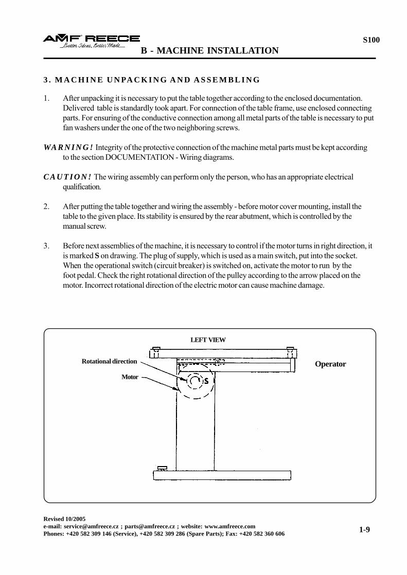


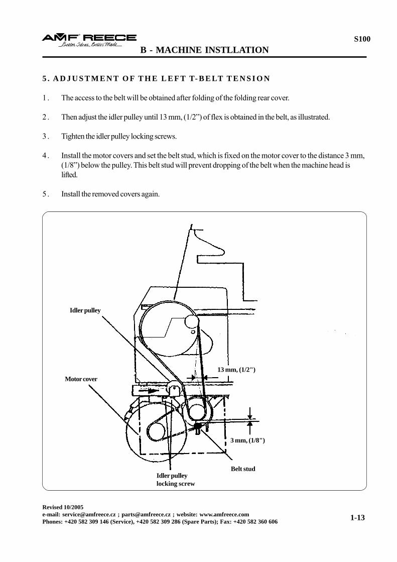


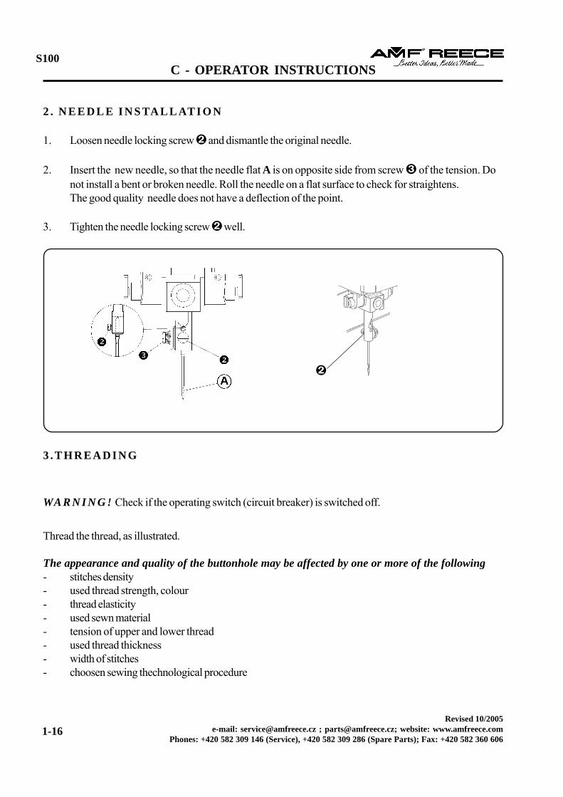

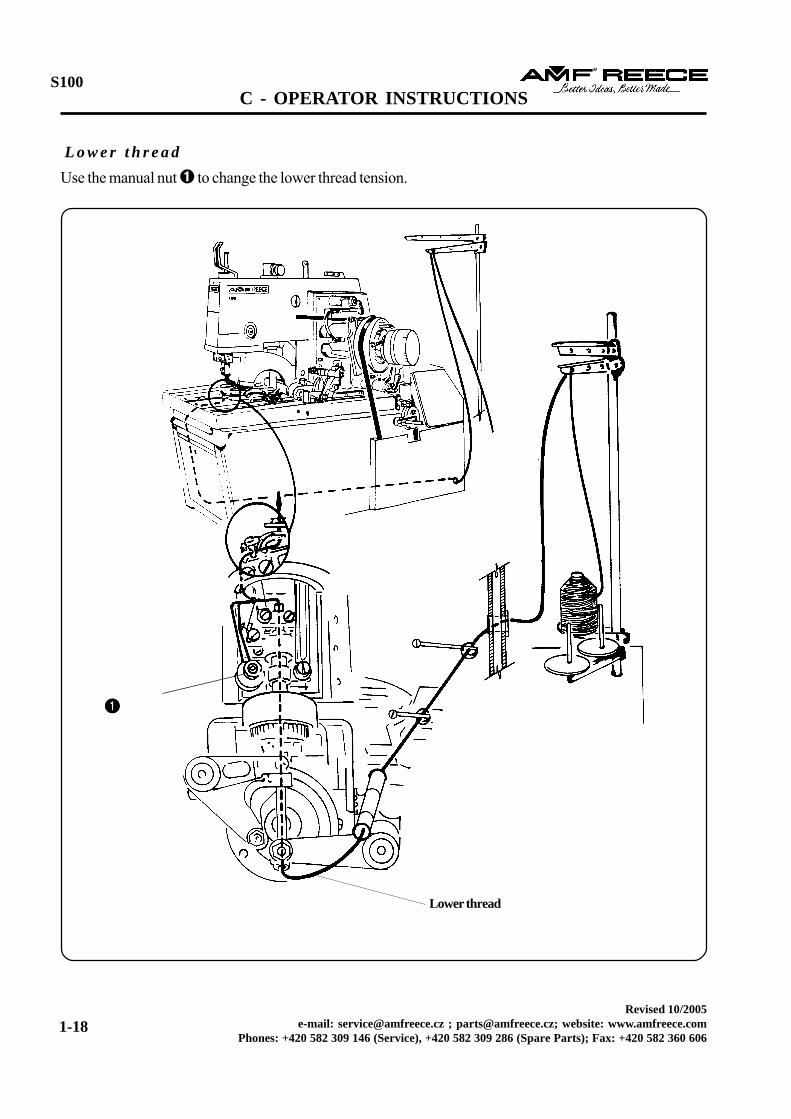


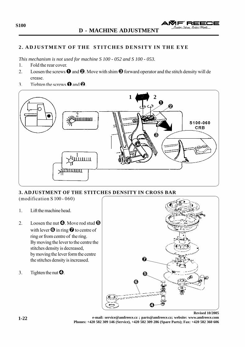


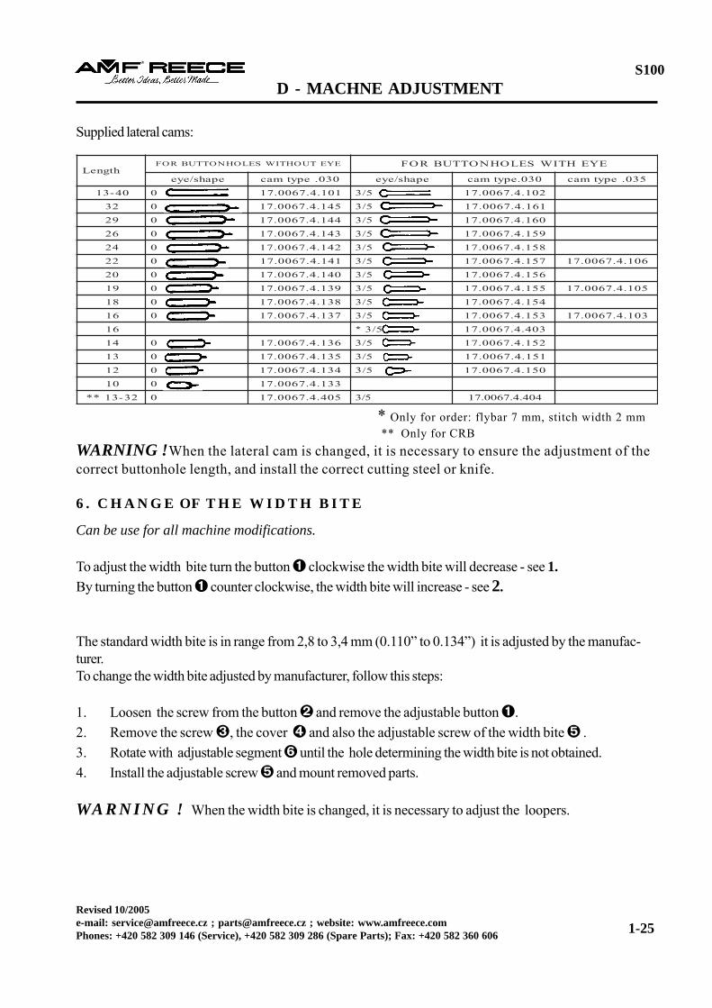


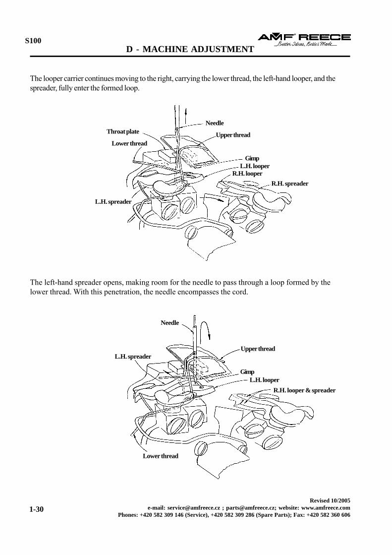


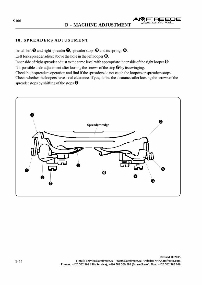


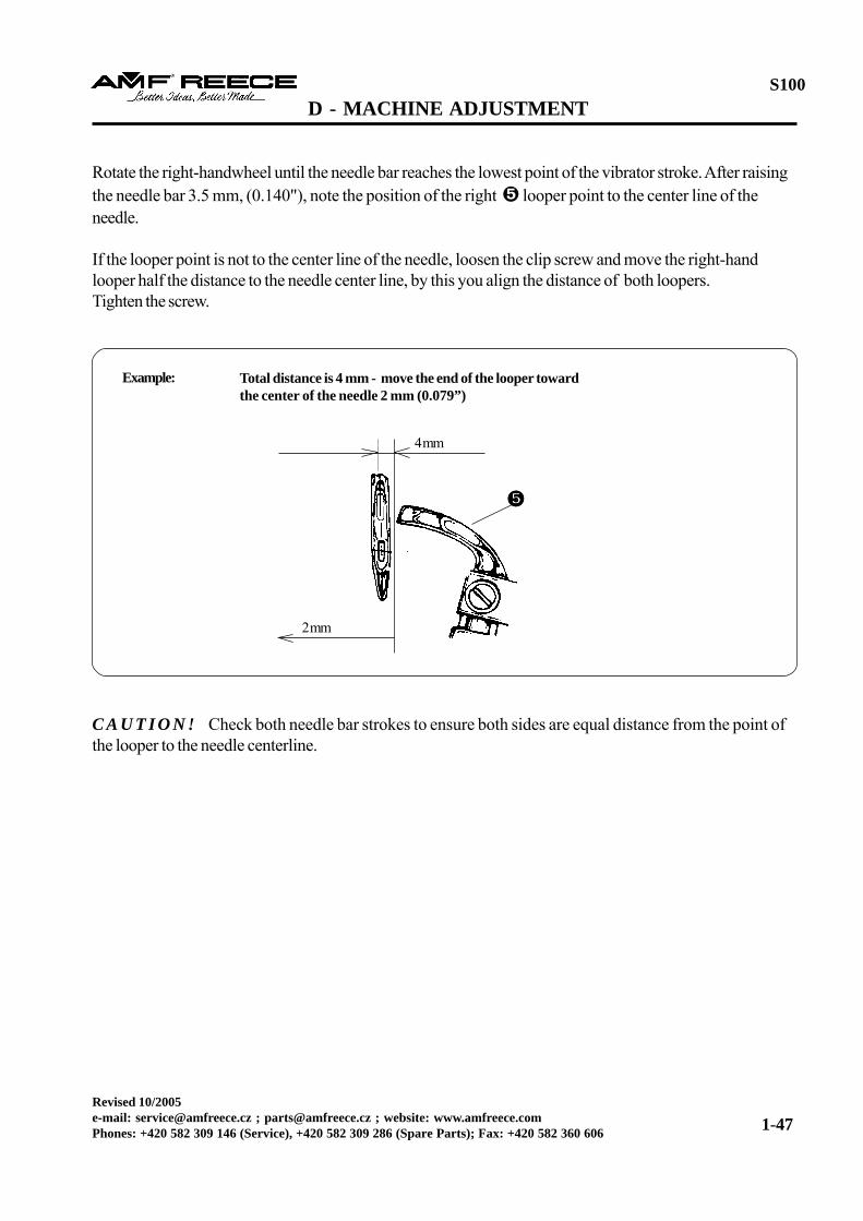


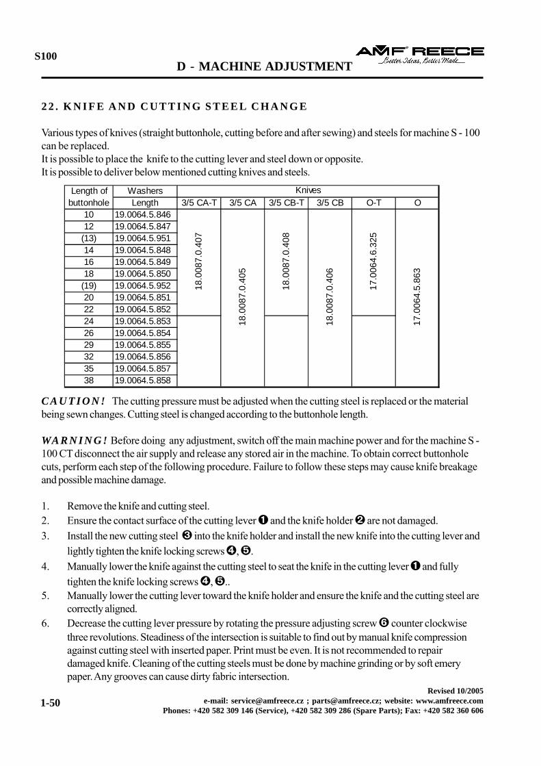


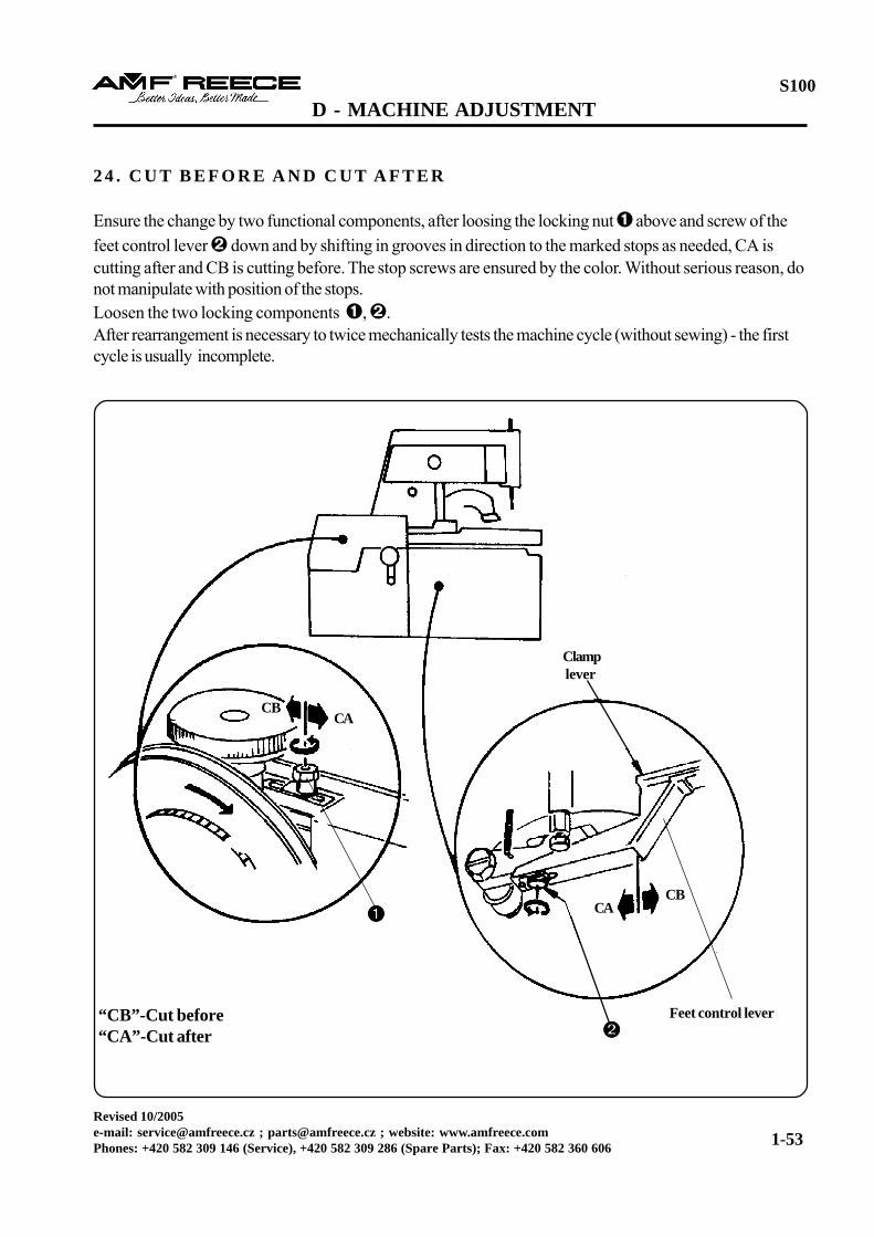


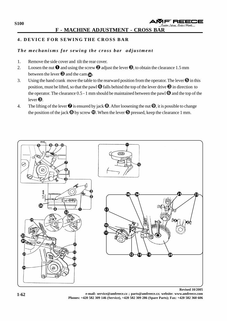

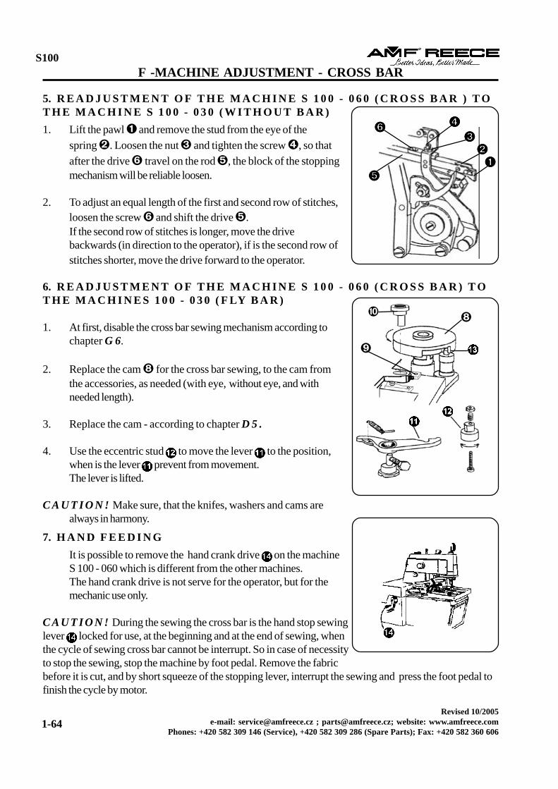


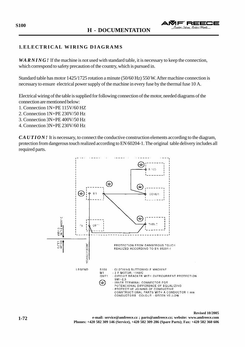
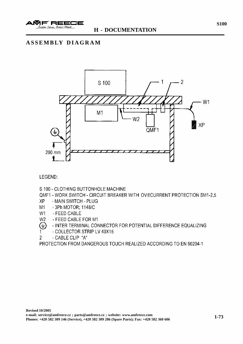
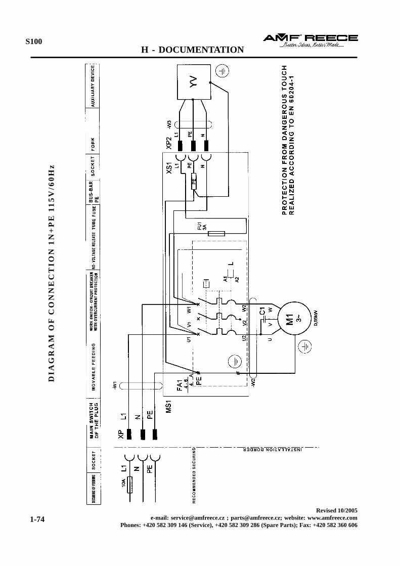


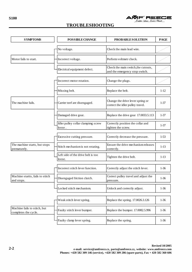
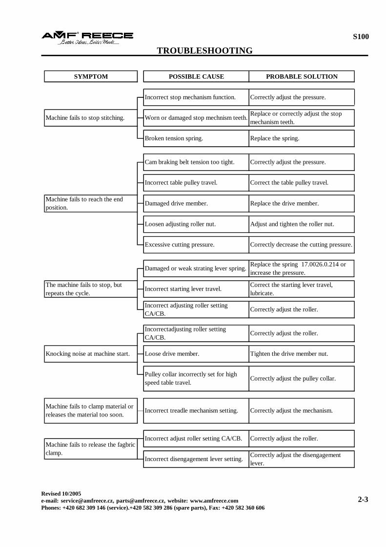
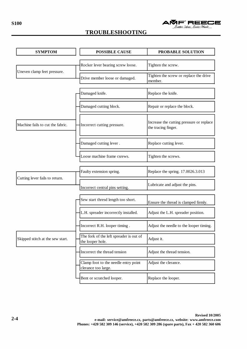


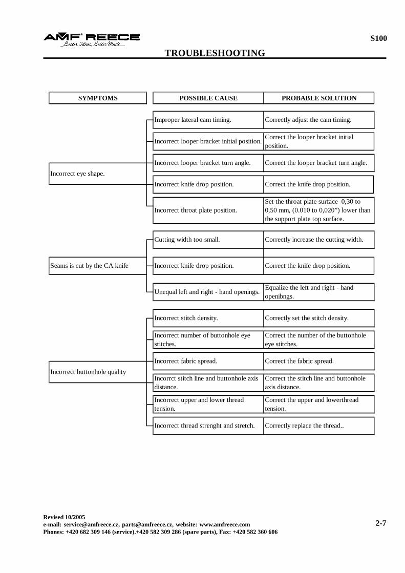

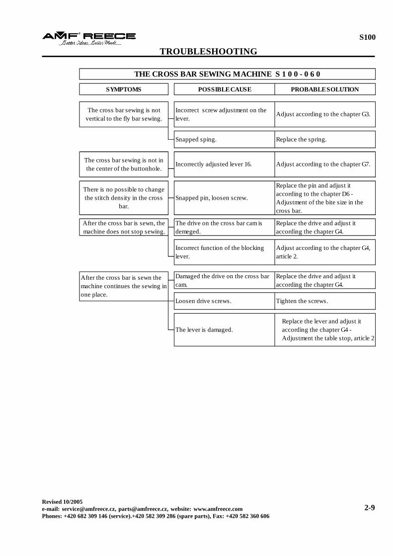


![blackpepperclothing.comblackpepperclothing.com/images/company_profile.pdf · Eyelet, Fusing machine] ... testing tools to conduct quality checks oh'"the finished garmenfé ensuring](https://static.documents.pub/doc/80x56/5ad667097f8b9a6d708e19ad/fusing-machine-testing-tools-to-conduct-quality-checks-ohthe-finished-garmenf.jpg)
