24
WARNING: Before putting tool in service, take to your immediate supervisor. Model SCP/SCPA Clamp Application, Operation and Maintenance Manual OM 211-SCP/A RENFROE Model SCP

WARNING: Before putting tool in service, take to your immediate supervisor.
Model SCP/SCPA Clamp Application, Operation and Maintenance Manual OM 211-SCP/A
RENFROE
Model SCP

This Operator’s Manual covers the Application, Operation and Maintenance of this RENFROE product. Operator’s Manuals for other current RENFROE products are available upon request. Direct Requests to J.C. Renfroe & Sons, Inc., Jacksonville, Florida 32201.
Operators Manual
J.C. RENFROE & SONS, INCORPORATED of Jacksonville, Florida, has been an international leader in the manufacture and mar-keting of Lifting Clamps for over fifty years. RENFROE products are manufactured in Jacksonville, Florida. A worldwide network of stock-ing distributors provides a readily available source of supply and service.
J.C. RENFROE & SONS, INCORPORATED Jacksonville, Florida 32201 Telephone: 904/356-4181 Toll Free: 1-800-874-8454 Fax: 904/354-7865 www.jcrenfroe.com
Copyright © 2001 J.C. Renfroe & Sons, Inc.

T H I S P U B L I C A T I O N S U P E R S E D E S A L L PREVIOUSLY PUBLISHED AND/OR DISTRIBUTED INFORMATION BY MANUFACTURER AND/OR ITS DISTRIBUTORS WITH RESPECT TO APPLICABLE RENFROE PRODUCTS AND SUBJECT MATTER DESCRIBED OR CONTAINED HEREIN.
NOTICE OF EXCLUSION OF WARRANTY
RENFROE HAS HEREIN SET FORTH IN CONSPICUOUS LANGUAGE AN EXCLUSION OF
ANY WARRANTY EITHER EXPRESSED OR IMPLIED, WHICH IS NOT SPECIFICALLY AND
PARTICULARLY CONTAINED HEREIN. PLEASE REFER TO THAT STATEMENT FOR
REPRESENTATIONS AND WARRANTIES OF PRODUCTS MANUFACTURED BY J.C. RENFROE &
SONS, INC.
WARNING: Prior to selection, operation and/or maintenance of RENFROE products, read and understand the infor-mation provided in this manual. The understanding and use of the Definitions are important in determining the limitations and proper appli-cation of RENFROE products. Failure to review and utilize recommended appli-cations, operation and maintenance instructions may result in serious injury to operator and others.


OPERATING AIDS (DO’S AND DON’TS)
1. DO read and understand the Operators Manual before using the clamp 2. DO Consult Operator’s Manual or RENFROE when in doubt. 3. DON’T Lift over workmen DON’T lift over Safety Areas or personnel. 4. Do attend a factory training class for establishing proper use of Renfroe
Products. 5. DO Lock clamp closed before lifting load. DON’T lift with lock in open or
“Lock Open” position. 6. DON’T Use a connection that may release the clamp. 7. DON’T attach clamp directly to crane hook. DO use a flexible connection
between crane and clamp shackle. DON’T use heavy flexible connection. 8. DO use correct clamp for job. DON’T use large capacity clamps to lift light
loads. 9. DO Use an adequate number of clamps to balance load. DON’T lift loads
that are not balanced. 10. DO Use clamps within their rated capacity. DON’T overload clamps 11. DO Inspect clamp before each lift, follow inspection and maintenance in-
structions outlined in this manual and use RENFROE replacement parts to assure proper operation of the clamp
12. DON’T Use clamp that has been overloaded. DO refer to pre-lift inspection in Operators Manual
13. DON’T Side load with a straight shackle clamp. DON’T lift from side with vertical clamp
14. DON’T Misuse. DON’T lift plate from bottom of plate stack. 15. DON’T Rush. DON’T lift more than one plate at a time with a vertical clamp. 16. DON’T Improvise. Always use correct clamp for job. DON’T lift plate hori-
zontally with a vertical lift only clamp. 17. DON’T Alter clamp. DON’T grind, weld or modify the clamp in any manner.

DEFINITIONS VERTICAL LIFT: The lifting of a single plate or member in which the lifting force exerted by the rigging is directly above and in line with the lifting shackle as shown in the illustration below.
VERTICAL TURN/LIFT: A vertical turn/lift clamp is a vertical lifting clamp spe-cifically intended to turn a single plate or member thru a ninety degree (90°) arc and back to vertical thru the same ninety degree (90°) arc or from horizon-tal to vertical to horizontal thru a one hundred and eighty degree (180°) arc. Refer to Application Section of specific Turn/Lift clamps for further detail. Dur-ing the turning operation the edge of the plate opposite the edge to which the clamp is attached should always be in contact with a supporting surface such as a factory floor and the load on the clamp not exceed one half rated capac-ity of clamp—refer to illustrations shown below.
HORIZONTAL LIFT: Clamps (used in pairs or multiples) are attached to the side edges of a plate or bundle of plates positioned horizontally to the floor level. The rigging attached to clamps is generally multi-legged slings with the connecting point of the slings being approximately centered between the distance separating the clamps. Refer to illustrations shown below. WARNING: The capacity of all hori-zontal clamps is based on a sling angle of sixty degrees (60°). See illustration below. Sling angles less than sixty degrees (60°) increase the load exerted on the clamps, Never exceed the rated capacity of a single clamp.
STEEL PLATES: Unless otherwise specified, lifting clamps are manufac-tured to handle hot-rolled steel plates whose Brinell Hardness does not ex-ceed 300. WARNING: Do not lift plates with coatings or mill scale that prevent the gripping surfaces of the clamp from making positive con-tact with the base metal. For applications not covered by the above information, secure written rec-ommendations from RENFROE. FINISHED AND POLISHED PLATES: Steel plates in this category have other than hot-rolled surfaces such as stainless steel, etc., are generally han-dled using non-marring clamps incor-porating smooth gripping surfaces. WARNING: For applications using clamps with serrated gripping sur-

faces on finished or polished plates, secure written recommendations from RENFROE. S T R U C T U R A L M E M B E R S —FABRICATED SECTIONS: Unless otherwise specified, clamps described as capable of handling structural mem-bers and fabricated sections are limited to hot-rolled steel whose Brinell Hard-ness does not exceed 300. WARN-ING: For applications not covered by the above information, secure written recommendations from RENFROE. RATED CAPACITY: The rated capac-ity of a RENFROE product is based on the product being in “new or as new” condition and represents the maximum load the product is to be subjected to when utilized in the manner described in this manual. Wear, misuse, abuse and other factors relating to usage may reduce the rated capacity. Shock load-ing and the factors listed must be taken into consideration when selecting a RENFROE product for a given applica-tion. PLATE THICKNESS: The minimum and maximum plate thickness a clamp specified for handling plates is capable of lifting. WARNING: Never use a clamp for lifting a plate where the plate thickness is less than or greater than the minimum and maxi-mum stenciled on the clamp. JAW OPENING: The minimum and maximum thickness of a member of clamp specified as having a JAW OPENING is capable of handling. WARNING: Never use a clamp on a member whose thickness is less than or greater than the range of jaw
opening stenciled on the clamp. OPERATING TEMPERATURES: Unless specified under the Application Section of the individual model, the approved operating temperature of RENFROE clamps is from zero de-grees Fahrenheit (-18 Celsius) to a maximum of 200 degrees Fahrenheit (+93 degrees Celsius). The minimum and maximum temperatures apply to both ambient and the material being handled by the clamp. WARNING: Secure written authorization from RENFROE before using clamps in temperatures other than shown. “HOT LIFTS”: The Model R and S clamps are available in modifications that are capable of making lifts where the temperatures of the member being lifted exceeds 200 degrees Fahrenheit (+93 degrees Celsius). Depending on conditions a lift may exceed 1000 de-grees Fahrenheit (538 degrees Cel-sius). The exact application and tem-peratures of the plates to be handled are critical in selecting the proper model. WARNING: Secure written instructions from RENFROE for all hot lift applications. LOCKING CLAMPS: Locking clamps are divided into the categories listed below. With the exception of the “Locking Wedge” and “Locking Screw” type the purpose of the locks are to facilitate the attaching and removing of the clamp from the member being han-dled. “LOCK CLOSED” - an overcenter spring loaded mechanism in which the spring exerts a force on the gripping cam when the lock handle is moved to the “Lock Closed” position. When the

handle is moved to unlocked position the force exerted by the spring is re-laxed and the gripping cam may be retracted by pushing the lifting shackle into body of clamp. Refer to the Op-eration Section of specific models of “Lock Closed” clamps for additional details. Typical “Lock Closed” clamps are Models DG, FR and M. “LOCK OPEN ONLY” - normally used on “Hot Lift” clamps and consists of a manually operated “Lock Stop Pin” that is inserted when gripping cam of clamp is retracted and removed when clamp is positioned on the plate. Tag line may be used to permit operator to re-move pin from a greater distance from clamp. Refer to the Operation Section of specific model of “Lock Open Only” clamps for additional details. Typical “Lock Open Only” clamp is the Model RO. “LOCK OPEN-LOCK CLOSED” - an over-center spring loaded mechanism in which the spring exerts a force on the gripping cam when the lock handle is moved to the “Lock Closed” position. When the handle is moved to the “Lock Open” the gripping cam is maintained in the retracted position for ease in in-stalling the clamp on a plate or mem-ber. The Model FRD contains individ-ual “Lock Open” and “Lock Closed” mechanisms that must be operated separately. Refer to the Operation Section of specific models of the “Lock Open-Lock Closed” clamps for addi-tional details. Typical “Lock Open-Lock Closed” clamps are Models FRD, R, S, SD, SEA, SX, TL, TLA and the J-Series. “LOCKING WEDGE” - is a fluted steel wedge that is driven in place with a
hammer. The body of the wedge is positioned in a slot in the clamp body with the fluted edges contacting the member to which the clamp is being attached. Refer to Operation Section of specific models of the “Locking Wedge” clamps for additional details. Typical “Locking Wedge” clamps are Model A1, B1, B2 and PB. ”LOCKING SCREW” - “Lock Screw” clamps depend on manually adjusting a screw to hold the gripping surface in place for lifting and removing the clamp from member being lifted. Refer to Operation Section of a specific model of “Locking Screw” clamps for addi-tional details. Typical “Locking Screw” clamps are Models AC, ACP, NM, PC, SCP and SCPA. NON-LOCKING: “Non-Locking” clamps have no mechanisms to aid in attaching or removing clamp from member being lifted. It is necessary to have position of clamp maintained on the member being lifted until a properly applied force is exerted to the lifting shackle. Refer to Operation Section of specific models of the “Non-Locking” clamps for additional details. Typical “Non-Locking” clamps are Model AST, ASTL, BD, HR, HDR and WHSR. WARNING: A pointing out and notice of danger. The purpose of a “WARNING” is to apprise the operator and all other affected persons of the existence of danger of which he should be but may not be aware and to enable the operator to protect himself and oth-ers where applicable against such dan-ger. An attempt is made herein to warn against reasonable and reasona-bly foreseeable danger in the proper use and possible reasonable misuse of RENFROE products described in this manual.

DESIGNATED PERSON — A person se-lected by the employer or the employer’s representative as being competent to per-form those specific duties. QUALIFIED PERSON — A person who, by possession of a recognized degree in an applicable field or certificate of professional standing, or who, by extensive knowledge, training, and experience, has successfully demonstrated the ability to solve problems relating to the subject matter at hand.

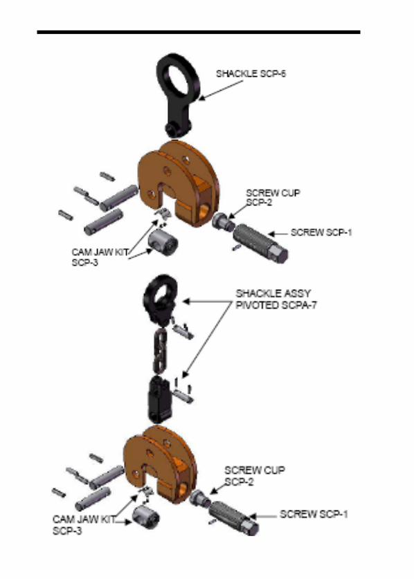
MODEL SCPA LOCKING SCREW MODEL SCP LOCKING SCREW Application SCP/SCPA The model “SCP” clamp is capable of handling steel plates from the horizontal through a hundred and eighty degree arc and may be used for handling plate at rolling and forming machines. Refer to Illustrations shown below. The adjusting screw is used to adjust clamp for various thicknesses of material and attach the clamp to members being lifted. The model “SCPA” has the same capabilities as the “SCP”, except the “SCP” is limited to 10 degrees side-loading on the shackle. The “SCPA” incorporates a pivoting shackle permitting 90 degrees side-loading. Re-fer to Definition Pages for explanation of “Screw Locking” clamp. The clamp features a spring-loaded pivoting cam jaw that “cams in” when a load is applied to the lifting shackle. For identification of component parts, refer to exploded view of clamp located at the end of the Maintenance Section.

WARNING: Refer to the sections on operation and maintenance for the approved procedures in the operation and maintenance of this product. OPERATION SCP/SCPA Step 1. Before using any RENFROE clamp, refer to the Application Section to confirm that the operation to be undertaken is an appropriate application for this prod-uct.

Step 2. Select appropriate capacity and plate thickness. The model designation, ca-pacity and plate thickness are stenciled on each clamp. WARNING: Never exceed rated capacity or use on material whose thick-ness is not within the range of jaw opening stenciled on clamp. Lift only one plate on each lift. Always use a clamp with maximum plate thickness and rated capacity near equal to the thickness and weight of the plate being lifted. Step 3. Inspect clamp before each lift. WARNING: Do not use if in need of repair. If in doubt, refer to Maintenance Section for detailed maintenance instructions and exploded view of the clamp for part identification. A. Check the clamp to be certain the Identification and warning
tags are present and legible. B. Do not use the clamp if the tags are missing or illegible C. Inspect gripping surfaces for wear and defects. Gripping surfaces must
be sharp and free of foreign matter. Screw cup mounted in screw should turn freely.
D. Screw should turn freely. Inspect for wear and damage. E. Spring must hold cam jaw in “Centered” position parallel to the screw. WARNING: Do not use clamp unless spring is in place and is holding the cam jaw parallel to length of screw. D. Inspect condition of body for wear and damage, particularly on the inside
of jaw opening. E. Inspect condition of lifting shackle and pins for wear and damage. F. Remove any clamp from service in need of repair. Step 4. The clamp is a component of the rigging used in the lifting or transporting of members. It is important to use safe and adequate rigging. WARNING: Improper or excessively heavy rigging may interfere with the operation of the clamp and its ability to maintain proper positions on the member. Never attach crane hook directly to the clamp - always use a flexible sling between crane hook and clamp. Step 5. Position clamp on the plate to be lifted. Do not allow inside of jaw opening to rest on plate to be lifted. Maintain 1/4” clearance. Refer to Illustration A.

On model “SCP”, position clamp so direction of force applied by crane is in line with the lifting shackle. WARNING: On model “SCP” never exceed ten degrees side loading. Refer to Photographs B, C, D and E.

Step 6. Tighten screw making certain both gripping surfaces are parallel to the sur-face of the member being lifted and are not partially on and off the edge of the plate. Refer to Illustration A, Step 5 and Illustration B. Using a bar, tighten screw. Do not over tighten. Refer to Photograph G and Chart H. WARNING: Apply required torque on screw, do not over-tighten. CHART H
Required Torque On Screw For Model “SCP/A/SP” Clamps Operator Operator Operator Capacity Operator Force Force In Force In Force In In In Pounds With Pounds with Pounds With Pounds With Tons Attached Handle 12” Lever 18” Lever 24” Lever . 1/2 40 21 14 - 1 1/2 40 26 18 - 3 50 34 23 - 6 - 78 52 - 8 - - 83 64 10 - - - 85 15 - - - 144 20 201 151
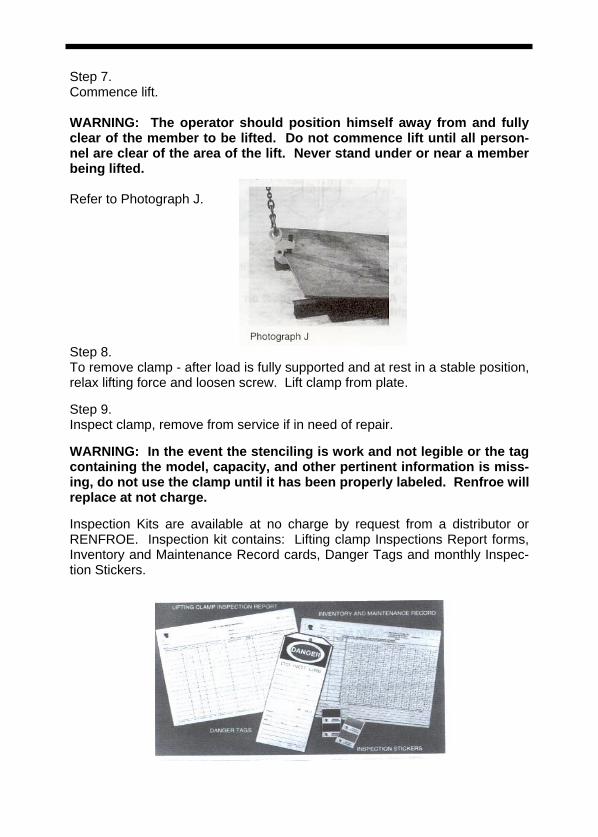
Step 7. Commence lift. WARNING: The operator should position himself away from and fully clear of the member to be lifted. Do not commence lift until all person-nel are clear of the area of the lift. Never stand under or near a member being lifted. Refer to Photograph J. Step 8. To remove clamp - after load is fully supported and at rest in a stable position, relax lifting force and loosen screw. Lift clamp from plate. Step 9. Inspect clamp, remove from service if in need of repair. WARNING: In the event the stenciling is work and not legible or the tag containing the model, capacity, and other pertinent information is miss-ing, do not use the clamp until it has been properly labeled. Renfroe will replace at not charge. Inspection Kits are available at no charge by request from a distributor or RENFROE. Inspection kit contains: Lifting clamp Inspections Report forms, Inventory and Maintenance Record cards, Danger Tags and monthly Inspec-tion Stickers.

Maintenance Program for Renfroe Clamps Manufactured from Steel The severity of service to which the clamp is subjected in the work place determines the frequency and type of inspection procedure required for the clamp. The frequency and type of inspection is determined by the clamp owner. Renfroe acknowledges the ASME B30.20 safety standard which sets forth minimum inspection requirements for “Below-the-Hook” lifting devices and the Renfroe Recommended Inspection Schedule meets and/or exceeds the ASME inspection recommendations.
Before using a clamp operators should be trained by a qualified person to visually inspect a lifting clamp that will include but not be limited to the following:
Every lift Inspection:
A visual inspection by the operator before and after each lift made by the clamp.
A. Check the clamp to be certain the Identification and warn-ing tags are present and legible.
B. Do not use the clamp if the tags are missing or illegible C. Inspect gripping surfaces for wear and defects. Gripping surfaces
must be sharp and free of foreign matter. Screw cup mounted in screw should turn freely.
D. Screw should turn freely. Inspect for wear and damage. E. Spring must hold cam jaw in “Centered” position parallel to the
screw. WARNING: Do not use clamp unless spring is in place and is hold-ing the cam jaw parallel to length of screw. D. Inspect condition of body for wear and damage, particularly on the
inside of jaw opening. E. Inspect condition of lifting shackle and pins for wear and damage.
Remove any clamp from service in need of repair.

WARNING: Do not use the clamp if in need of repair.
If, during the every lift inspection, the operator believes the clamp exhibits excessively worn parts or is damaged, the clamp should be inspected by a qualified person who will make a determination as to its fitness to make a lift. At this time the condition of the clamp should be noted and recorded. After in-spection by the qualified person it may be decided that a peri-odic inspection procedure is necessary.
Frequent Inspection: A visual inspection (see every lift inspection) by an operator or other designated person timed according to the clamps service class.
• Normal Service: monthly • Heavy Service: weekly to monthly • Severe Service: daily to weekly.
If, during the frequent lift inspection, the operator believes the clamp exhibits excessively worn parts or is damaged the clamp should be inspected by a qualified person who will make a de-termination as to its fitness to make a lift. At this time the condi-tion of the clamp should be noted and recorded. After inspec-tion by the qualified person it may be decided that a periodic inspection procedure is necessary. Periodic Inspection: A recorded inspection by a qualified person as described in the Periodic Inspection Procedure below timed according to the clamps service class.
• Normal Service: annual • Heavy Service: semi-annual • Severe Service: quarterly.
If during any inspection a condition is found which leads to a periodic inspection then the next periodic inspection is due from the time the clamp is returned to service. For example un-der a Normal Service schedule, one year from the time the clamp is returned to service. Renfroe recommends that a periodic inspection be conducted if any hazardous condition is found.

Warning: If any hazardous condition is found that may cause injury to the operator or other personnel then the clamp should be subjected to a Periodic Inspection by a Qualified Person.
Repair (replacement of worn parts) During regular maintenance when replacing parts that are worn a record should be made of the parts replaced. After the replacement of worn parts clamps need not be load tested. Repair (replacement of damaged parts) During a repair in which parts are replaced due to damage a record should be made of the repair. At this time the clamp should be marked with the following information as per the ASME B30.20 requirements:
• Name and address of the repairer • Repairer’s unit identification • Clamp weight (if altered) • Rated load (if altered) • ASME BTH-1 Design Category (if altered) • ASME BTH-1 Service Class (if altered)
Model SCP/A Periodic Inspections Step 1. Verify the identity of the clamp by checking the I. D. plate on the clamp body. If the I. D. plate is missing or not legible an RFID chip (Radio Frequency Identification Device) is embedded in the clamp body or a clamp component. If the I. D. plate is missing and the RFID chip is un-available call the Renfroe factory for instructions on returning the clamp for recertification. Step 2. Completely disassemble clamp. Step 3. Remove all dirt, grease and other matter that may inhibit proper inspection of the clamp body or clamp components. Step 4. BODY A. Inspect welds for fractures. RENFROE recommends a dye pene-
trant or similar method of detecting indications on the clamp. If an indication is found it may be necessary to use a magnetic particle, ultrasonic or similar methods for determining damage to the clamp or components.
B. Inspect inside surfaces of body side-plates that come in contact with shackle and shackle yoke for wear and damage.
C. Inspect all pin holes for wear and elongation. D. Inspect inside of jaw opening for displaced metal and distortion. Refer to
exploded view. WARNING: Replace clamps containing fractures, elongated holes, dis-torted jaw opening, distorted and worn threads and jaw openings, with displaced metal. Step 5. SCREW SCP-1 A. Inspect for distortion, damaged threads and wear. B. Inspect for fractures, particularly in the area in which the screw cup
mounts and on opposite end where holes are provided for spud wrench or bar.
C. Inspect set screw and threaded hole for damage and distortion.

WARNING: Replace screws that are bent, have distorted and worn threads, contain fractures and have damaged threads in set screw hole. Step 6. SCREW CUP SCP-2 A. Inspect screw cup for fractures, damage and wear. Serrations must be
sharp and free of imperfections and foreign matter. B. Screw cups must turn freely in the screw. When installing screw cup, in-
sert lubricant in recess of screw. Recommended lubricant is powdered graphite or Molybdenum Disulfide grease. Drive spirol pin thru the body of the screw. For capacities greater than 50 tons: Insert screw cup, tighten set screws in screw, making certain that the set screws are positioned in the circular groove provided in the screw cup. Refer to exploded view. Tighten screws until screws lock on screw cup.
C. Back up on set screw until point is just clear of screw cup but still within the circular groove. Rotate screw cup 360 degrees to make certain that the set screws do not bind on screw cup. Refer to exploded view.
D. Attempt to remove screw cup from screw. Spirol pin will prevent removal when properly positioned.
WARNING: Replace worn, dull or damaged screw cups. Step 7. CAM JAW SCP-3 A. Inspect cam jaw for fractures, damage and wear. Serrations must be
sharp and free of imperfections and foreign matter. B. Check pin holes for fractures and wear. The cam jaw is supplied with gripping serrations on both ends. When one set of gripping serrations is dull or damaged, the cam jaw may be reversed to pro-vide new gripping surfaces. WARNING: Inspect cam jaw body and pin hole for fractures and wear before using reverse side of gripping surface. Replace cam jaws that are worn, have dull or damaged gripping surfaces or contain fractures. Step 8. SPRING SCP-4 A. Inspect spring for damage or distortion. B. Inspect spring retaining screws. Both screws must be in place. C. Spring must be in place before installing cam jaw. Spring must be de-
pressed to aid in installing cam jaw pin.

WARNING: Do not use clamp without spring or with a spring that does not hold cam jaw parallel to screw. Replace if damaged, distorted or does not hold cam jaw parallel to screw. Step 9. SHACKLE PIN and CAM PIN SCP-5 A. Inspect all pins for: 1. Distortion. 2. Surface blemishes. 3. Wear. 4. Fractures. WARNING: Replace pins that are distorted, have surface scars, are worn or contain fractures. Step 10. LIFTING SHACKLE and LIFTING SHACKLE PIVOTED ASSEMBLY SCP-6 and SCPA-7 A. Inspect lifting shackle eye for elongation and wear at point where the eye
engages sling attachment. B. Inspect shackle pin hole for wear and elongation. C. Inspect shackle body for bending. D. SCPA-7: Inspect shackle yoke for damage, wear and distortion, particu-
larly in the area where the shackle yoke engages the side-plates of the clamp body. Refer to exploded view.
E. SCPA-7: Inspect shackle yoke pivot pin. Refer to details on lifting shackle SCP-6 and cam pin SCP-5, steps 8 and 9. Refer to exploded view.
WARNING: Replace shackles that have elongated shackle eye, are worn or distorted and have elongated pin holes.

Step 11. HANDLE ASSEMBLY SCPH-8 (Optional) A. Inspect handle for distortion or damage. B. Make certain that the retaining spirol pin is installed evenly and does not
project out from one side of the handle or the other. Refer to exploded view.
WARNING: Replace handles that are damaged or distorted. Step 11. ASSEMBLY After reassembly, check operation of clamp. All parts should move freely without binding. Refer to exploded view for proper location of component parts. WARNING: All retaining pins and fasteners must be in place. GENERAL RENFROE products may be returned to the factory for inspection and refur-bishment in accordance with an established fee schedule. Use only RENFROE replacements parts. Refer to RENFROE catalog for in-structions on ordering replacement parts. WARNING: Do not weld, grind or modify the clamp body or component parts in any manner. In the event the stenciling is worn and not legible or the tag containing the model, capacity or other pertinent information is missing - do not use clamp until it has been properly labeled. RENFROE will replace tag at no charge upon request.

EXCLUSION OF WARRANTY
THERE EXISTS NO WARRANTIES NEITHER EX-PRESSED NOR IMPLIED WHICH EXTEND BE-YOND THE DESCRIPTIONS OR STATEMENTS
CONTAINED IN THE FACE OR ANY PART HEREOF.
J.C. RENFROE & SONS, INC. P.O. Box 4279 · 1926 Spearing Streeet · Jacksonville, Florida 32206 Phone: U.S.A. Toll Free (800) 874-8454 (in Florida 904/356-4181) Facsimile: 904/354-7865 · Internet: www.jcrenfroe.com


