17
Model: TM1-TS WiFi RF

1Model: TM1-TS WiFi RFModel: TM1-TS WiFi RF

2 Time Clock Series 2Model: TM1-TS WiFI RF
Table of Contents1
2
3-4
5-6
7-9
9-10
11
11
12
13-14
15-16
16
Product Image
Table of Contents
Installation Procedure
LCD Display
WiFi Setup
Security Types and Compatibility
Remote Access Via Web App
Remote Access Via Web Browser
Setting the Clock
Pairing with the RC1-W receiver
Pairing with the UH1-W
Testing Comms. with the UH1-W
Model: TM1-TS WiFi RF
Time Clock Series1
Operating Modes
Setting the Operating Mode
Clean Screen
Locking the Time Clock
Holiday Programming
Programming 5/2 Day & 7 Day Time Clock Mode
Setting Countdown Mode
Time Clock Override
Factory Reset
Optional Features Explained
Wiring Diagrams
17
18
19
19
20
21-22
23
24
25-26
27
28-30
17

43 Time Clock Series Model: TM1-TS WiFi RF
1 2
3 4
Installation Procedure
This time clock is designed to be flush mounted and requires a back box of 35mm (minimum depth) to be sunk into the wall prior to installation.
Step 1Carefully separate the front half of the time clock from the back plate by placing a small flat head terminal driver into the slots on the bottom face of the time clock.
Step 2Place the time clock front somewhere safe.Terminate the time clock as shown in the diagrams on pages 28-30 of this booklet.
Step 3Screw the time clock back plate securely into the back box.
Step 4Clip the front of the time clock back onto the time clock back plate.
DoMount the time clock at eye level.Read the instructions fully so you get the best from our product.
Don’tDo not install near to a direct heat source as this will affect functionality.Do not push hard on the LCD screen as this may cause irreparable damage.

65 Time Clock Series Model: TM1-TS WiFi RF
1 432 5
12
1. Day Indicator - Displays the day.
2. Holiday Indicator - Displayed when the time clock is in Holiday mode.
3. Output Hold - Displayed when the time clock is in Hold mode.
4. Clock - Displays time in normal operation, time left in hold or days left in holiday mode.
5. Up/Down Keys - Increase or decrease values shown on top digit group.
6. Keypad Lock Icon - Displayed when the keypad is locked.
7. ON/OFF Keys - Use to override the timed output. Press and hold OFF to turn the display off.
8. WiFi Icon - Displayed when a WiFi connection is established.
9. Clean Screen - Freezes screen temporarily to enable cleaning.
10. Cancel - Used to exit setup/program operations.
11. Setup/Programming Keys - Used to navigate setup options.
12. Timer Status - Displays the current status of the timed output.
13. Comfort Level Selection Keys - Used in comfort level setup (see page 17).
LCD Display
9
11
13
6
10
78

87 Time Clock Series Model: TM1-TS WiFi RF
Setting Up Your WiFi Time ClockStep 1: Download and install the WiFi thermostat setup utility from our web site: www.heatmiser.co.uk/wifiStep 2: Connect the time clock to your PC with the USB cable provided. This will power the time clock through the USB port and will allow you to test the WiFi connection.Open the setup utility and press Read to view the current time clock configuration.Step 3:Enter the SSID, Security Type and Security Code of your wireless network.These settings can usually be found on the underside of your wireless router.For more information please consult your router manual.See page 11 for additional information on security types and compatibility.Step 4:Enter a fixed IP address for your WiFi time clock outside of the router DHCP range.
It is likely that your network will be configured to operate on a DHCP basis.This means your router automatically issues an IP address to a device that successfully connects to the network.
Your WiFi time clock needs a fixed IP address in order for local and remote access to operate and you must set this up manually.
Log into your wireless router and navigate to the LAN settings page.
Find and select the DHCP setup details.This should define the IP range that can be assigned to devices connecting to the network.As an example, you may have an IP starting range 192.168.1.1 and ending 192.168.1.99. This means you can safely provide your WiFi time clock the IP address 192.168.1.100 as no other devices will be assigned this address by the router.If your DHCP range is from 192.168.1.1 to 192.168.1.253 you cannot use 254 or above.You need to change the DHCP range, taking care not to change any of the first 3 numbers.Tip! When setting up an IP address, the first three sets of numbers must be the same as the router IP address and the fourth set must not be used elsewhere on the network.Step 5: Enter the Subnet mask for the network.This information can usually be found on the underside of your wireless router.Step 6: Enter the IP address of your gateway and DNS. In most cases, this is the IP address of your wireless router.If you have a multi-zone system and are using the Multi-Link, the Gateway of the time clock will need to be configured as the IP address of the Multi-Link.

109 Time Clock Series Model: TM1-TS WiFi RF
Step 7: Create a unique username and password that will be used to access your time clock from a web browser.
Default Username: admin Default Password: admin
Change these settings to your personal preference and record for future use.
A 4 digit access PIN is required to use the smartphone/tablet app and also helps to secure your system.
Step 8: When you have entered the details of your WiFi network press Apply and disconnect the USB cable, (the time clock LCD should go blank).Reconnect the USB cable to the WiFi time clock, when the time clock has rebooted it will attempt to connect to your network. This process takes approximately one minute and is complete when the WiFi symbol is displayed on screen.
Security Types and CompatibilityThe WiFi time clock operate on the 802.11b standard.
If your router is a G model, you must ensure it is setup to work in B&G mode. You will not be able to connect to your time clock without changing this setting on G model routers.
There are currently 4 common methods of securing your wireless connection:OPEN/DISABLED (not recommended)W.E.P. (lowest security level)
Your choice of security settings in the time clock must match the setting in your router. Often you will find WPA and WPA2 are a single option in the router.This is perfectly normal as the router automatically selects the correct security level and you can set the time clock up using either one of these settings.
Passwords can be up to 63 characters in length including spaces _. / \ characters.The W.E.P. option is not so simple. Some routers generate a hidden password from a pass phrase whilst others require a 10 or 26 digit hex password and won’t accept anything else. Your time clock utility can deal with both options but the following restrictions may apply:
A hex password can only be made up of the numbers 0 to 9 and the letters a to f (lower case only).
Hex passwords can only be 10 characters or 26 characters in length.
If a passphrase is used it must be either 5 or 13 characters in length but can be any letter or number.Your time clock will automatically calculate the same hidden password your router creates from the same phrase.
These restrictions are common to most routers but you should refer to the router manual for specific restrictions that apply to your model.
W.P.A. (medium security) W.P.A.2. (highest security)

1211 Time Clock Series Model: TM1-TS WiFi RF
To remotely connect to your WiFi time clock you must forward a port within your router to your WiFi time clock.
As all routers are setup differently, you should consult your user manual or the manufacturer’s website for more information.
Generally you should create a new service within your router. Within this service you must open TCP port 8068.
Use the port forwarding function to forward the new service to the IP address of your WiFi time clock.
Remote Access via App
To remotely access your WiFi time clock via a web browser you must first open port 80 and forward this to the IP address of your WiFi time clock.
Remote Access via Web Browser
To connect to your time clock, open your preferred browser and enter the IP address that you gave the time clock during setup and press enter.
You will be asked to enter a password and username.These are both set to “admin” as default.
We recommend you change these settings to ensure the security of your system.
For further information, click the help link within the browser.
To set the clock, follow these steps.
• Press PROG and then CLOCK ..........................................................................
• Use the Down key to set the hours ....................................................................
• Use the Up key to set the minutes .....................................................................
• Press the CLOCK key ................................................................................................
• Use the Down key to set the day ........................................................................
• Use the Up key to set the month ........................................................................
• Press the CLOCK key ................................................................................................
• Use the Up/Down keys to set the year ........................................................
• Press DONE to confirm and exit ..........................................................................
Setting the Clock
MinutesChange Minutes
HoursChange Hours

1413 Time Clock Series Model: TM1-TS WiFi RF
• To pair the time clock with the receiver, press and hold the SCREEN button for 10 seconds .......................................................................
Pair SuccessfulThe address of the receiver will flash on the time clock display and the Comms LED on the receiver will flash and then go out to indicate the pair is successful. • Press DONE to confirm the pairing ................................................................
Pair FailIf the Comms LED does not flash there is a problem with the RF signal and you should reduce the distance between the time clock and receiver.Where possible ensure there are no metal objects blocking the signal.Check features 06 - 08 have been configured correctly.
Comms LED
To pair the time clock with the RC1-W receiver, follow these steps.
On the receiver; Press the and hold the Pairing button until the Communication LED lights up.
On the time clock; • Press PROG and then SETUP .................................................................................
• The display will now show feature 06 (Receiver Type) at the topThe options within feature 06 are: 00 = UH1-W or 01 = RC1-W receiver.
• Use the central Up/Down keys to set feature 06 to 01 (RC1-W) ..................
• Use the Up key at the top to select 07 (Receiver Address) .......................................
• You can now select a Receiver Address from 01-32.Use the Up/Down keys to set the RC1-W Receiver address .........................(You must set a unique receiver address for each receiver installed).
• Use the Up key to select 08 (Zone Number) .................................................................
• You are able to connect two TM1-TS WiFi RF time clocks to one RC1-W receiver.Use the Up/Down keys to select the zone this time clockcontrols (01 or 02) ........................................................................................................
• Press DONE to confirm and exit .......................................................................................
Pairing with the RC1-W ReceiverIf using with the UH1-W wiring centre, turn to page 15.

1615 Time Clock Series Model: TM1-TS WiFi RF
• On the time clock use the Up key to adjust the set temperatureabove the room temperature ............................................................................
• Press DONE ...............................................................................................................
Testing Communications with the UH1-W
On the UH1-W:Set the board address number, choose from 01-09 on the rotary switch.Note: Each UH1-W will need a different address.
On the time clock:
• Press PROG and then SETUP .................................................................................
• The display will now show feature 06 (Receiver Type) at the top.The options within feature 06 are: 00 = UH1-W or 01 = RC1-W receiver.
• Use the central Up/Down keys to set feature 06 to 00 (UH1-W) ...................
• Use the Up key at the top to select 07 (Receiver Address) ........................................
• You can now select a board address from 01-09.Use the Up/Down keys to set the UH1-W board address ...............................
• Use the Up key to select 08 (Zone Number) ..................................................................
• You are able to connect eight WiFi RF thermostats / time clocks to one UH1-W.Use the Up/Down keys to select the zone this time clock
• controls (01 - 08) ..............................................................................................................
• Press the Up key at the top of the screen to select feature 09 ..................................
You will now see the flame icon and the assigned zone on the UH1-W should now be active.
If the output on the UH1-W is not activated, reduce the distance between the time clock and the UH1-W and check features 06-09 have been setup correctly, then repeat the above process.
Pairing with the UH1-W • Use the Up/Down keys in the centre of the screen to select if the time clock will bring on the pump & boiler outputs ............................00 = UFH Zone (Outputs enabled)01 = Radiator Zone (Outputs not enabled)
• Press DONE to confirm and exit ...............................................................................

1817 Time Clock Series Model: TM1-TS WiFi RF
Operating Modes The time clock has three main operating modes.
The time clock can be used to control various electrical devices in and around your home e.g. lighting, electric towel rails, hot tubs, sauna’s etc.
Refer to the manufacturer instructions for wiring to these devices.
Common time clock wiring requirements are shown in the diagramson pages 28-30.
00
01
02
MODE
5/2 Day Time ClockIn this mode, you can program 4 switching times for the weekdays and 4 different switching times for the weekend.
7 Day Time ClockIn this mode, you can program 4 switching times for each day of the week.
Countdown TimerIn this mode, the time clock will activate the output during the countdown period.
DESCRIPTION
To select the mode, follow these steps.
• Press the PROG key .................................................................................................................
• Press the SETUP key ................................................................................................................
• Use the Up/Down keys at the top of the screen to select featurenumber 16 .......................................................................................................................
• Use the Up/Down keys in the center to adjust the setting ...........................00 = 5/2 Day, 01 = 7 Day, 02 = Countdown timer.
• Press DONE to confirm settings and exit .........................................................................
Setting the Operating Mode
Mode
Feature
2019 Time Clock Series Model: TM1-TS WiFi RF
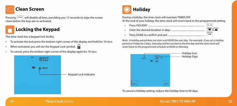
Locking the KeypadThe time clock has a keypad lock facility.
• To activate the lock press the bottom right corner of the display and hold for 10 secs.
• When activated, you will see the Keypad Lock symbol.
• To cancel, press the bottom right corner of the display again for 10 secs.
Pressing will disable all keys, providing you 15 seconds to wipe the screen clean before the keys are re-activated.
Keypad Lock Indicator
During a holiday, the time clock will maintain TIMER OFF.At the end of your holiday, the time clock will revert back to the programmed setting.
• Press HOLIDAY ..............................................................................................
• Enter the desired duration in days ........................................................
• Press DONE to confirm and exit .............................................................
To cancel a Holiday setting, reduce the holiday time to 00 days.
Holiday
Note: A holiday period does not start until 00:00 the next day. For example, if you set a holiday period on Friday for 2 days, Saturday will be counted as the first day and the time clock will revert back to the programmed schedule at 00:00 on Monday.
Holiday IconHoliday Days
Clean Screen

2221 Time Clock Series Model: TM1-TS WiFi RF
Programming 5/2 Day and 7 Day Modes• Use the Up/Down keys to set the OFF time for TIME 1 ..................
• Repeat these steps for the TIME 2, TIME 3 & TIME 4 ........................
• Press DAY to select the next day to program and repeat ..............
• When complete, press DONE to confirm settings and exit ............
In 5/2 Day mode the time clock will display “Sat Sun” prompting you to program the
switching times for the weekend.
In 7 Day mode, the time clockwill display Tue.
Default switching times are pre-programmed but you can change them easily.
Weekday On Time Off TimeWake 07:00 09:00Leave 16:00 20:00Return --,-- --,--Sleep --,-- --,--Weekend On Time Off TimeWake 07:00 09:00Leave 16:00 20:00Return --,-- --,--Sleep --,-- --,--
To set the switching times, follow these steps.
• Press PROG ............................................................................................................................
• Select TIME 1 .........................................................................................................................
• TIME 1 and ON will flash.
• Use the Up/Down keys to set the ON time for TIME 1 .....................................
• Press OFF .................................................................................................................................

2423 Time Clock Series Model: TM1-TS WiFi RF
Timer OverrideThe time clock is able to override its current timer status.
• Press HOLD ........................................................................................................................
• If the timer status is currently on press OFF ..........................................................
• If the timer status is currently off press ON ..........................................................
You will see the timer status change and flash to confirm it has been overridden.
The time clock will return to the program at the next programmed time.
To cancel the Override, repeat the steps above.
Countdown Mode
• Use the Up/Down keys to set the countdown duration ..........................
• Press DONE to confirm and exit ..............................................................................
• Hold Left will appear showing the time left.
When Hold Left is displayed on screen, the output will be active.
To cancel the Countdown, follow the same steps but reduce the time to 00:00.
Hold Left Icon
Hold Time
Timer Status(Flashes in Override)
ON/OFF keys

2625 Time Clock Series Model: TM1-TS WiFi RF
THE FOLLOWING SETTINGS ARE OPTIONAL AND IN MOST CASESNEED NOT BE ADJUSTED
Feature 06 – UH1-W or RC1-W Receiver: The thermostat can work with our UH1-W 8 zone wiring centre or RC1-W 2 channel receiver. This setting determines which is being used.
Feature 07 – Receiver Address: Within one building, up to 9 UH1-W’s or 32 RC1-W’s can be used. Each receiver must have a unique receiver address.
Feature 08 – Zone Number: This is the zone number you are assigning the thermostat to on either the UH1-W or the RC1-W receiver. 01 - 08 - UH1-W, 01 - 02 – RC1-W.
Feature 09 – Underfloor Heating or Radiator Zone (UH1-W Only): This setting determines whether the thermostat will activate the pump & boiler output on the UH1-W. If set to 00 the outputs will be activated. 00 = UFH, 01 = Radiators.
Feature 10 – Fail Safe: If enabled, the thermostat will send a signal to the receiver every 20 minutes. Should the receiver fail to receive two signals, the receiver will activate the output for 20% of the time. This is to protect the system against a loss of wireless signal and in case the thermostat battery fails whilst you are away.
Feature 16 - Programming Mode: This function allows you to select between 5/2 Mode, 7 Day mode or Countdown timer.
Optional Features Explained
06
07
08
09
10
16
FEATURE
Receiver Type
Receiver Address
Zone Number
UFH or Radiators (UH1-W only)
Fail Safe
Program Mode
DESCRIPTION
00 = UH1-W, 01 = RC1-W
UH1-W = 01-09, RC1-W = 01-32
UH1-W = 01-08, RC1-W = 01-02
00 = UFH, 01 = Radiators
00 = Disabled, 01 = Enabled
00 = Weekday/Weekend (Default)01 = 7 Day Programming02 = Countdown mode
SETTING
Optional Settings - Feature Table
To adjust the optional settings, follow these steps.
• Press PROG ...........................................................................................................................• Press SETUP ..........................................................................................................................• Use the Up/Down keys at the top of the screen to select the feature
number (shown above) and then use the Up/Down keys in the center to adjust the setting ..........................................................................................................
• Press DONE to confirm settings and exit ...................................................................
Adjusting the Optional Settings

2827 Time Clock Series Model: TM1-TS WiFi RF
All icons displayed simultaneously. Factory reset is complete.
The thermostat has a reset function to restore all settings to their factory defaults.
To perform a factory reset, follow these steps.
• Press & hold the OFF key to turn the thermostat display OFF ...............................
• Press and hold the bottom left corner of the LCD for 10 seconds.
• All of the screen icons will appear for 2 seconds and then disappear.
• Press the ON key once to turn the thermostat display back ON ...........................
Factory Reset Wiring Diagram - TM-TS WiFi RF
RecommendationsMax Cable Size - 1.5mmBack Box Depth - 35mm
N.B. The TM1-TS WiFi RF is designed to work with the RC1-W and the UH1-W. Please refer to the appropriate diagram for connections to your heating system.
NeutralLive
Mains Supply From Fused Spur
TM1-TS WiFi RF
N L RT2 -
Timer
RemoteAir Sensor

3029 Time Clock Series Model: TM1-TS WiFi RF
Wiring Diagram2x TM1-TS WiFi RF with RC1-W Receiver
Wiring Diagram - TM-TS WiFi RF with RC1-W Receiver, Combination Boiler System
To Boiler
N
S/L P/L
LMains Supply In
S/L = Switched Live P/L = Permanent Live
P/L and S/L connections will vary depending on the boiler model but will normally be connected to the thermostat connections.
230VAC
RC1-W
B1 A2 A1B2 N L
230VAC
RC1-W
B1 A2 A1B2 N L
P/L and S/L connections will varydepending on the boiler model but will normally be connected to the thermostat connections.
N.B Valves must have end switches
Two Zone Heating System
N
L
N
LMains Supply In
Heating Zone 2 Valve
Heating Zone 1 ValveP/L
To BoilerS/L N
L
Neutral
*
= Neutral*

31 Time Clock Series
Twitter: heatmiseruk
Facebook: facebook.com/thermostats
Want More Information?Call our support team on: +44 (0)1254 669090Or view technical specifications directly on our website: www.heatmiser.com
PDF FAQ
Heating Professionals:Request a copy of our productinstallation guide containingdetailed technical specificationsfor our complete product range:www.heatmiser.com/guide


