International OPEN ACCESS Journal Of Modern Engineering Research (IJMER) | IJMER | ISSN: 2249–6645 | www.ijmer.com | Vol. 4 | Iss. 5| May. 2014 | 26 | Modeling and Structural Analysis of Ladder Type Heavy Vehicle Frame V. Vamsi Krishnam Raju 1 , B. Durga Prasad 2 , M. Balaramakrishna 3 , Y. Srinivas 4 1, 2, 3, 4 (Department of Mechanical Engineering, Vishnu Institute of Technology, India) I. Introduction Automotive chassis is a French word that was initially used to represent the basic structure. It is a skeletal frame on which various mechanical parts like engine, tires, axle assemblies, brakes, steering etc. are bolted. It gives strength and stability to the vehicle under different conditions. At the time of manufacturing, the body of a vehicle is flexibly molded according to the structure of chassis. Automobile chassis is usually made of light sheet metal or composite plastics. It provides strength needed for supporting vehicular components and payload placed upon it. Automotive chassis or automobile chassis helps keep an automobile rigid, stiff and unbending. It ensures low levels of noise, vibrations and harshness throughout the automobile. Automobile chassis without the wheels and other engine parts is called frame. Automobile frames provide strength and flexibility to the automobile. The backbone of any automobile, it is the supporting frame to which the body of an engine, axle assemblies are affixed. Tie bars that are essential parts of automotive frames are fasteners that bind different auto parts together. Automotive frames are basically manufactured from steel. Aluminum is another raw material that has increasingly become popular for manufacturing these auto frames. In an automobile, front frame is a set of metal parts that forms the framework which also supports the front wheels. 1.1 Types of frames There are three types of frames 1. Conventional frame 2. Integral frame 3. Semi-integral frame 1.1.1 Conventional frame It has two long side members and 5 to 6 cross members joined together with the help of rivets and bolts. The frame sections are used generally. a. Channel Section – Good resistance to bending b. Tabular Section – Good resistance to Torsion c. Box Section – Good resistance to both bending and Torsion 1.1.2 Integral frame This frame is used now in most of the cars. There is no frame and all the assembly units are attached to the body. All the functions of the frame carried out by the body itself. Due to elimination of long frame it is cheaper and due to less weight most economical also. Only disadvantage is repairing is difficult. Abstract: The automobile is divided into two parts body and chassis. The chassis is basic structure of a vehicle. It contain all the engine parts and power systems but the frame is the main portion of chassis which do not contain any other assemblies like engine parts. Its principle function is to safely carry the maximum load for all designed operating conditions. This paper describes modeling and structural analysis of conventional type heavy vehicle frame. Weight reduction is now the main issue in automobile industries. In the present work, the dimensions of an existing heavy vehicle frame of a TATA 1109 EX2 vehicle is taken for modeling and analysis. The vehicle frame is initially modeled by considering ‘C’ cross section in SOLID WORKS 2011 and then it is imported to ANSYS 13.0. The analysis is done with three different composite materials namely Carbon/Epoxy, E-glass/Epoxy and S- glass/Epoxy subjected to the same pressure as that of a steel frame. The design constraints are stresses and deformations. The results are then compared to finalize the best among all the four frames. Keywords: frame, Auto CAD 2012, SOLID WORKS 2011, ANSYS 13.0, TATA 1109 EX2.
Transcript
International
OPEN ACCESS Journal Of Modern Engineering Research (IJMER)
Modeling and Structural Analysis of Ladder Type Heavy Vehicle
Frame
V. Vamsi Krishnam Raju1, B. Durga Prasad
2, M. Balaramakrishna
3, Y. Srinivas
4
1, 2, 3, 4 (Department of Mechanical Engineering, Vishnu Institute of Technology, India)
I. Introduction Automotive chassis is a French word that was initially used to represent the basic structure. It is a
skeletal frame on which various mechanical parts like engine, tires, axle assemblies, brakes, steering etc. are
bolted. It gives strength and stability to the vehicle under different conditions. At the time of manufacturing, the body of a vehicle is flexibly molded according to the structure of
chassis. Automobile chassis is usually made of light sheet metal or composite plastics. It provides strength
needed for supporting vehicular components and payload placed upon it. Automotive chassis or automobile
chassis helps keep an automobile rigid, stiff and unbending. It ensures low levels of noise, vibrations and
harshness throughout the automobile.
Automobile chassis without the wheels and other engine parts is called frame. Automobile frames
provide strength and flexibility to the automobile. The backbone of any automobile, it is the supporting frame to
which the body of an engine, axle assemblies are affixed. Tie bars that are essential parts of automotive frames
are fasteners that bind different auto parts together. Automotive frames are basically manufactured from steel.
Aluminum is another raw material that has increasingly become popular for manufacturing these auto frames. In
an automobile, front frame is a set of metal parts that forms the framework which also supports the front wheels.
1.1 Types of frames
There are three types of frames
1. Conventional frame
2. Integral frame
3. Semi-integral frame
1.1.1 Conventional frame It has two long side members and 5 to 6 cross members joined together with the help of rivets and bolts. The
frame sections are used generally.
a. Channel Section – Good resistance to bending
b. Tabular Section – Good resistance to Torsion c. Box Section – Good resistance to both bending and Torsion
1.1.2 Integral frame This frame is used now in most of the cars. There is no frame and all the assembly units are attached to the
body. All the functions of the frame carried out by the body itself. Due to elimination of long frame it is cheaper
and due to less weight most economical also. Only disadvantage is repairing is difficult.
Abstract: The automobile is divided into two parts body and chassis. The chassis is basic structure of a
vehicle. It contain all the engine parts and power systems but the frame is the main portion of chassis which do not contain any other assemblies like engine parts. Its principle function is to safely carry the
maximum load for all designed operating conditions. This paper describes modeling and structural
analysis of conventional type heavy vehicle frame. Weight reduction is now the main issue in
automobile industries. In the present work, the dimensions of an existing heavy vehicle frame of a TATA
1109 EX2 vehicle is taken for modeling and analysis. The vehicle frame is initially modeled by
considering ‘C’ cross section in SOLID WORKS 2011 and then it is imported to ANSYS 13.0. The
analysis is done with three different composite materials namely Carbon/Epoxy, E-glass/Epoxy and S-
glass/Epoxy subjected to the same pressure as that of a steel frame. The design constraints are stresses
and deformations. The results are then compared to finalize the best among all the four frames.
Keywords: frame, Auto CAD 2012, SOLID WORKS 2011, ANSYS 13.0, TATA 1109 EX2.
Modeling and Structural Analysis of Ladder type Heavy Vehicle Frame
1.1.3 Semi – Integral frame In some vehicles half frame is fixed in the front end on which engine gear box and front suspension is mounted.
It has an advantage when the vehicle is met with an accident the front frame can be taken easily to replace the damaged chassis frame. This type of frame is used in American and European cars.
1.2 Functions of the frame
1. To carry load of the passengers or goods carried in the body.
2. To support the load of the body, engine, gear box etc.,
3. To with stand the forces caused due to the sudden braking or acceleration.
4. To with stand the stresses caused due to the bad road condition.
5. To with stand centrifugal force while cornering.
1.3 Various loads acting on the frame 1. Short duration Load – While crossing a broken patch. 2. Momentary duration Load – While taking a curve.
3. Impact Loads – Due to the collision of the vehicle.
4. Inertia Load – While applying brakes.
5. Static Loads – Loads due to chassis parts.
6. Over Loads – Beyond Design capacity.
II. Problem Specification
Weight reduction is now the main issue in automobile industries. Because if the weight of the vehicle
increases the fuel consumption increases. At the same time as the weight of the vehicle increases the cost also increases which becomes a major issue while purchasing an automobile. For example if we take frame of TATA
1109 EX 2 heavy vehicle frame. It is manufactured with Structural Steel. Steel structures exposed to air and
water, such as bridges are susceptible to corrosion. In conditions of repeated stress and more temperatures it can
suffer fatigue and cracks. These are the main problems of steel and these are compensated by inducing
composite materials.
2.1 Composite Materials
A composite material is defined as a material composed of two or more materials combined on a
macroscopic scale by mechanical and chemical bonds. Unique characteristic of many fiber reinforced
composites is their high internal damping capacity. This leads to better vibration energy absorption within the
material and results in reduced noise transmission to neighboring structures. Many composite materials offer a
combination of strength and modulus that are either comparable to or better than any traditional metallic metals.
Because of their low specific gravities, the strength to weight-ratio and modulus to weight-ratios of these composite materials are markedly superior to those of metallic materials. The fatigue strength to weight ratios
as well as fatigue damage tolerances of many composite laminates are excellent. For these reasons, fiber
composites have emerged as a major class of structural material and are either used or being considered as
substitutions for metals in many weight-critical components in aerospace, automotive and other industries.
High damping capacity of composite materials can be beneficial in many automotive applications in
which noise, vibration, and hardness is a critical issue for passenger comfort.
2.2 Specifications of Existing Heavy Vehicle TATA 1109 EX2 Frame
Sl.
No. Description
Dimension
(mm)
1 Wheel base 3600
2 Front track 1800
3 Rear track 1690
4 Overall length of vehicle with
load body 6600
5 Max. width 2270
6 Frame length 5620
Modeling and Structural Analysis of Ladder type Heavy Vehicle Frame
III. Design Design may be done in two ways one way is the component design which is done by improving the
existing ones. The other is conceptual design where there is no reference and creation of new machines. A new or better machine is one which is more economical in the overall cost of production and operation. The process
of design is a long and time consuming one. From the study of existing ideas, a new idea has to be conceived.
The idea is then studied keeping in mind its commercial success and given shape and form in the form of
drawings. In the preparation of these drawings, care must be taken about the availability of resources like
money, man power and materials required for the successful completion of the new idea into an actual reality. In
designing a machine component, it is necessary to have a good knowledge of many subjects such as
Mathematics, Engineering Mechanics, Strength of Materials, Theory of Machines, Workshop Processes and
Engineering Drawing.
Generally the design of a component involves various steps in it. Initially, the drawings must be drawn
in user friendly software and they must be converted into a 3D model. This 3D model must be imported into an
analyzing medium where it is structurally or thermally analyzed to sustain the need. Different steps involved in designing a component are
1. Part drawing
2. Modeling
3. Structural analysis
The present frame is divided in to individual components and each component is drawn, modeled and
structurally analyzed by using software and its procedure is explained as below.
3.1 Part Drawing
It is a document that includes the specifications for a part's production. Generally the part drawings are
drawn to have a clear idea of the model to be produced. The part drawing of the entire frame is drawn with all
the views in AUTO CAD 2012.
Fig. 3.1 Part drawing of assembly in AUTO CAD 2012
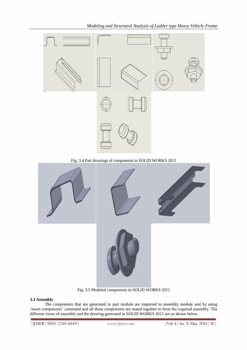
3.2 Modeling
It is the process of developing a mathematical representation of any three-dimensional surface of object
via specialized software. The product is called a 3D model.
Modeling and Structural Analysis of Ladder type Heavy Vehicle Frame
It is steel construction material, a profile, formed with a specific shape or cross section and certain
standards of chemical composition and mechanical properties. Structural steel shape, size, composition, strength, storage, etc., is regulated in most industrialized countries. Composition 0.565%C, 1.8% Si, 0.7%Mn,
0.045%P and 0.045% S
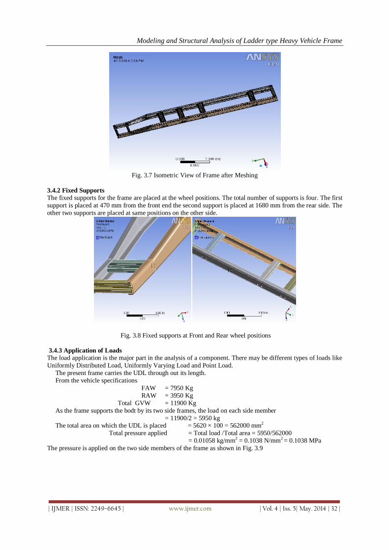
3.5.1 Mass of Frame
The mass of an object is a fundamental property of the object, a numerical measure of its inertia, a fundamental
measure of the amount of matter in the object.
Mathematical equation for mass is
Mass = Volume × Density
We know, Density of steel = 7850kg/m3
Volume of frame = 4.9104×10⁻² m³
Total mass of frame = 7850 × 0.049104 = 385.46 kg
3.5.2 Stresses developed in Frame
It is a physical quantity that expresses the internal forces that neighboring particles of a continuous material
exert on each other. For example, when a solid vertical bar is supporting a weight, each particle in the bar pulls
on the particles immediately above and below it. These macroscopic forces are actually the average of a very
large number of intermolecular forces and collisions between the particles in those molecules. There are many
types of stresses developed in a component. The frame is analyzed by considering Equivalent stress and normal
stress.
Normal stress
The component of stress which is perpendicular to the plane on which the force is applied is called Normal
stress. This stress is also called as principle stress. Its value should not exceed the yield strength of the material.
In some of the situations design is considered to be safe if its value is less than the yield strength of the material. The normal stress distribution in the frame for structural steel is as shown in Fig. 3.10. From the Fig. 3.10 it can
be inferred that
Maximum normal stress = 3359 Mpa
Minimum normal stress = - 6317 Mpa
Modeling and Structural Analysis of Ladder type Heavy Vehicle Frame
Fig. 3.12 Total deformation in frame (Structural steel)
3.6 Carbon/ Epoxy
Carbon-Fiber-Reinforced Polymer, Carbon-Fiber-Reinforced Plastic or Carbon-Fiber- Reinforced
Thermo Plastic (CFRP, CRP, CFRTP or often simply carbon fiber, or even carbon) is an extremely strong and
light Fiber-Reinforced Polymer which contains carbon fibers.
The binding polymer is often a thermo set resin such as epoxy, but other thermoset or thermoplastic polymers,
such as polyester, vinyl ester or nylon, are sometimes used. The composite may contain other fibers, such as aramid e.g. Kevlar, Twaron, Aluminium or Glass fibers as well as Carbon fiber. The properties of the final
CFRP product can also be affected by the type of additives introduced to the binding matrix (the resin). The
most frequent additive is silica, but other additives such as rubber and carbon nanotubes can be used. CFRPs are
commonly used in the transportation industry; normally in cars, boats and trains, and in sporting goods industry
for manufacture of bicycles, bicycle components, golfing equipment and fishing rods.
Although carbon fiber can be relatively expensive, it has many applications in aerospace and automotive fields,
such as Formula One racing and wherever high strength-to-weight ratio and rigidity are required such as sailing
boats and rowing shell hulls, top-end bicycles and motorcycles, As manufacturing techniques improve and costs
reduce it is becoming increasingly common in small consumer goods that require strength, lightness and
stiffness such as laptop bodies, tripod legs, tent poles, fishing rods, hockey sticks, bows and arrows, racquet
An individual structural glass fiber is both stiff and strong in tension and compression that is, along its
axis. Although it might be assumed that the fiber is weak in compression, it is actually only the long aspect ratio
of the fiber which makes it seem so i.e., because a typical fiber is long and narrow, it buckles easily. On the
other hand, the glass fiber is weak in shear that is, across its axis. Therefore if a collection of fibers can be
arranged permanently in a preferred direction within a material, and if the fibers can be prevented from buckling
in compression, then that material will become preferentially strong in that direction. Furthermore, by laying
multiple layers of fiber on top of one another, with each layer oriented in various preferred directions, the
stiffness and strength properties of the overall material can be controlled in an efficient manner. In the case of
fiberglass, it is the plastic matrix which permanently constrains the structural glass fibers to directions chosen by
the designer. With chopped strand mat, this directionality is essentially an entire two dimensional plane; with woven fabrics or unidirectional layers, directionality of stiffness and strength can be more precisely controlled
within the plane.
E-Glass / Epoxy Resin Composites are extremely strong materials used in roofing, pipes and automobiles.
Composition: 54% SiO2 - 15% Al2O3 - 12% CaO
3.7.1 Mass of frame
Mathematical equation for mass is
Mass = Volume × Density
We know Density of E-glass/Epoxy = 2600 kg/m3
Volume of Frame = 4.9104×10⁻² m³
Total mass of Frame = 2600 × 0.049104 = 127.67 kg
3.7.2 Stresses Developed in Frame
The two types of stresses are considered for analyzing the frame and their respective stress distributions
are as shown
Fig. 3.16 Normal Stress Distribution in Frame (E-glass/ Epoxy)
Maximum normal stress = 2887.9 = 2888 Mpa (Approx.)
Minimum normal stress = -4205.4 = -4205 Mpa (Approx.)
Modeling and Structural Analysis of Ladder type Heavy Vehicle Frame
Fig. 3.17 Equivalent Stress Distribution in Frame (E-glass/ Epoxy)
Maximum Equivalent stress = 17055 Mpa
Minimum Equivalent stress = 0 MPa
3.7.3 Deformation
Fig. 3.18 Total Deformation in Frame (E-glass/ Epoxy)
Maximum deformation = 9.45 mm
Minimum deformation = 0 mm
3.8 S-glass/ Epoxy
The manufacturing process for glass fibers suitable for reinforcement uses large furnaces to gradually
melt the silica sand, limestone, kaolin clay, fluorspar, colemanite, dolomite and other minerals to liquid form.
Then it is extruded through bushings, which are bundles of very small orifices (typically 5–25 micrometers in
diameter for E-Glass, 9 micrometers for S-Glass). These filaments are then sized (coated) with a chemical
solution. The individual filaments are now bundled together in large numbers to provide a roving. The diameter
of the filaments, as well as the number of filaments in the roving determines its weight. Common uses of S-glass include high performance aircraft (gliders), boats, automobiles, baths, hot tubs,
septic tanks, water tanks, roofing, pipes, cladding, casts, surfboards and external door skins.
Composition: 64% SiO2- 24% Al2O3- 10% MgO
3.8.1 Mass of Frame
Mathematical equation for mass is
Mass = Volume × Density
We know Density of S-glass/ epoxy = 2495 kg/m3
Volume of frame = 4.9104×10⁻² m³
Total mass of frame = 2495 × 0.049104 = 123 kg (Approx.)
Modeling and Structural Analysis of Ladder type Heavy Vehicle Frame
Fig. 4.5 Graphical representation of Equivalent stress
V. Conclusion Present used material for chassis is steel. We have considered polymeric composites like Carbon/Epoxy,
E-glass/Epoxy and S- glass /Epoxy for chassis material. By employing a polymeric composite heavy vehicle
chassis for the same load carrying capacity, there is a reduction in weight of 70% to 80%. Based on the results it was inferred that Carbon/Epoxy polymeric composite heavy vehicle chassis has superior strength, less
deformation, less normal stress and less weight compared to steel, E-glass/Epoxy and S- glass /Epoxy.
So we conclude that it is better to use Carbon/ Epoxy as a material for frames of heavy vehicle chassis. So
that the fuel consumption decreases for the vehicles.
REFERENCES [1] Vijaykumar V. Patel, "Structural analysis of a ladder chassis frame," World Journal of Science and Technology
2012, 2(4)05-08 [2] Cicek Karao a journal on analysis of a chassis frame with joints was performed by using software [3] M. Ravi Chandra, S. Sreenivasulu & Syed Altaf Hussain, "Modeling And Structural Analysis Of Heavy Vehicle
Chassis Made Of Polymeric Composite Material By Three Different Cross Sections", Journal of Mechanical and Production Engineering Research and Development (IJMPERD), ISSN 2249-6890, Vol.2, Issue 2,Sep 2012 45-60.
[4] C. Karaoglu, N. S. Kuralay, Stress analysis of a truck chassis with riveted joints, Finite Elements in Analysis and
Design, 38, (2002), 1115-1130. [5] N.V.Dhandapani, Dr. G Mohan Kumar, Dr K.K.Debnath, Static Analysis of Off-High Way Vehicle Chassis supporting Structure for the effect of various Stress distributions IJART, Vol.2 Issue 1, 2012, 1-8. [6] Sairam Kotari, V.Gopinath,"Static and dynamic analysis on Tatra chassis" International Journal of Modern Engineering Research (IJMER), Vol.2, Issue.1, pp-086-094. [7] K.W. Poh, P.H. Dayawansa, A.W. Dickerson, I.R. Thomas, Steel membrane floors for bodies of large rear-
dump mining trucks, Finite Elements in Analysis and Design 32, (1999), 141-161. [8] H J Beermann, English translation by Guy Tidbury, The Analysis of Commercial Vehicle Structures, Verlag
TUV Rheinland GmbH Koln-1989. [9] Mohd Husaini Bin Abd Wahab, "Stress Analysis of Truck Chassis", Project Report University Malaysia Pahang,
2009 [10] Machine Tool Design hand book by Central Machine Tool Institute Edition 1 – 2004 Mc Graw Hill Publications [11] http://ansys.com/Industries/Academics/Tools/Curriculum+Resources