SANDIA REPORT SAND2009-4520 Unlimited Release Printed August 2009 Modeling of Pulsating Heat Pipes Richard C. Givler and Mario J. Martinez Prepared by Sandia National Laboratories Albuquerque, New Mexico 87185 and Livermore, California 94550 Sandia is a multiprogram laboratory operated by Sandia Corporation, a Lockheed Martin Company, for the United States Department of Energy’s National Nuclear Security Administration under Contract DE-AC04-94AL85000. Approved for public release; further dissemination unlimited.
Transcript
SANDIA REPORT SAND2009-4520 Unlimited Release Printed August 2009
Modeling of Pulsating Heat Pipes Richard C. Givler and Mario J. Martinez Prepared by Sandia National Laboratories Albuquerque, New Mexico 87185 and Livermore, California 94550
Sandia is a multiprogram laboratory operated by Sandia Corporation, a Lockheed Martin Company, for the United States Department of Energy’s National Nuclear Security Administration under Contract DE-AC04-94AL85000.
Approved for public release; further dissemination unlimited.
2
Issued by Sandia National Laboratories, operated for the United States Department of Energy by Sandia Corporation. NOTICE: This report was prepared as an account of work sponsored by an agency of the United States Government. Neither the United States Government, nor any agency thereof, nor any of their employees, nor any of their contractors, subcontractors, or their employees, make any warranty, express or implied, or assume any legal liability or responsibility for the accuracy, completeness, or usefulness of any information, apparatus, product, or process disclosed, or represent that its use would not infringe privately owned rights. Reference herein to any specific commercial product, process, or service by trade name, trademark, manufacturer, or otherwise, does not necessarily constitute or imply its endorsement, recommendation, or favoring by the United States Government, any agency thereof, or any of their contractors or subcontractors. The views and opinions expressed herein do not necessarily state or reflect those of the United States Government, any agency thereof, or any of their contractors. Printed in the United States of America. This report has been reproduced directly from the best available copy. Available to DOE and DOE contractors from U.S. Department of Energy Office of Scientific and Technical Information P.O. Box 62 Oak Ridge, TN 37831 Telephone: (865) 576-8401 Facsimile: (865) 576-5728 E-Mail: [email protected] Online ordering: http://www.osti.gov/bridge Available to the public from U.S. Department of Commerce National Technical Information Service 5285 Port Royal Rd. Springfield, VA 22161 Telephone: (800) 553-6847 Facsimile: (703) 605-6900 E-Mail: [email protected] Online order: http://www.ntis.gov/help/ordermethods.asp?loc=7-4-0#online
3
SAND2009-4520 Unlimited Release
Printed August 2009
Modeling of Pulsating Heat Pipes
Richard C. Givler and Mario J. Martinez Thermal and Fluid Processes Department 01514
Sandia National Laboratories
P.O. Box 5800 MS0836
Albuquerque, New Mexico 87185
Abstract
This report summarizes the results of a computer model that describes the behavior of pulsating heat pipes (PHP). The purpose of the project was to develop a highly-efficient (as compared to the heat transfer capability of solid copper) thermal ground-plane (TGP) using silicon carbide (SiC) as the substrate material and water as the working fluid.
4
ACKNOWLEDGMENTS The modeling work described, herein, was part of a joint project among Northrop Grumman Electronic Systems, the University of Missouri, the Georgia Institute of Technology and Sandia National Laboratories. It was funded by DARPA/MTO, proposal number 015070924. We appreciate the many helpful discussions with Melissa Carter, Harry Chen, Anurag Chandorkar and Tony Hirt, all of Flow Science Inc., during the development of the flow model. Insight into the subtleties of heat pipe operation were graciously shared with us by John Rosenfeld of Thermacore International Inc.
Review and Analysis of Some Existing PHP Models .................................................................... 8 Literature Review...................................................................................................................... 8
Comments on the Evaporation/Condensation Model..................................................... 9 Some Results from the Zhang Model ..................................................................................... 10
Over-Damped Oscillations ........................................................................................... 14 Remarks on the Zhang Model ...................................................................................... 15
CFD Models of PHPs using FLOW-3D ...................................................................................... 15 The FLOW-3D CFD Simulator .............................................................................................. 15 A Simple, FLOW-3D Model .................................................................................................. 17 The One-Loop, 2-Turn Model ................................................................................................ 19 The One-Loop, 4-Turn Model ................................................................................................ 22
Distribution .................................................................................................................................. 31
6
7
INTRODUCTION Northrop Grumman Electronic Systems (NGES), the University of Missouri, the Georgia Institute of Technology and Sandia National Laboratories (SNL) have a three-year multi-faceted program to develop an advanced, SiC-based, thermal ground-plane (TGP). A well-designed thermal ground-plane is any device that transports heat from a source to an ambient environment with high efficiency. Work at all four institutions was funded by DARPA/MTO. The current report summarizes that portion of the project performed by SNL during Phase I (January 2008 – March 2009). Sandia was tasked with providing modeling support for the development of the TGP. In the following pages we summarize the modeling work that was completed in Phase I. In particular, and in collaboration with the University of Missouri and NGES, we have focused on trying to understand the hallmarks of the pulsating heat pipe, which is anticipated to provide a major contribution to high heat transfer rates in the TGP. A closed loop pulsating heat pipe (PHP) consists of a capillary-sized tube or channel arranged in a serpentine configuration (see Figure 12) and joined end to end (e.g. Khandekar & Groll, 2004). Typically, the interior tube volume is evacuated and subsequently partially filled (primed) with a working fluid. If the capillary diameters are not too large, the fluid distributes itself into an arrangement of liquid slugs separated by vapor bubbles (often referred to as plugs). The serpentine structure is heated at one end (evaporator), while cooled at the opposite end (condenser). In between is often an adiabatic region, at least in PHPs constructed from tubing. During operation, heat is transferred by a pulsating action of the slugs and vapor bubbles. This pulsation appears as a non-equilibrium chaotic process, whose continuous operation requires non-equilibrium conditions to exist in, at least, some of the parallel channels. As with most heat pipes, no external power source is needed to either initiate or sustain the fluid motion or the transfer of heat. The objective of this project is to develop a multi-physics model for this complex phenomenon to assist with an understanding of how PHPs operate and to be able to understand how various parameters (geometry, fill ratio, materials, working fluid, etc.) affect its performance. The physical processes describing a PHP are highly coupled. Understanding its operation is further complicated by the non-equilibrium nature of the interplay between evaporation/condensation, bubble growth and collapse or coalescence, and the coupled response of the multiphase fluid dynamics among the different channels. A comprehensive theory of operation and design tools for PHPs is still an unrealized task. In the following we first analyze, in some detail, a simple model that has been proposed to describe PHP behavior. Although it includes fundamental features of a PHP, it also makes some assumptions to keep the model tractable. In an effort to improve on current modeling practice, we constructed a model for a PHP using some unique features available in FLOW-3D, version 9.2-3 (Flow Science, 2007). We believe that this flow modeling software retains more of the salient features of a PHP and thus, provides a closer representation of its behavior. There have been a number of experimental studies on PHPs. Here, we summarize the most important findings of some of these researchers. Khandekar and Groll (2004) considered a one-loop PHP experiment as a primary building block for a multi-turn PHP. They found: (i.) a
8
number of distinct flow regimes arise that depend on the input power, (ii.) gravity has an effect on the liquid/vapor motion, and (iii.) oscillations stopped when the PHP is in a horizontal orientation. Moreover, they found a complete stop-over configuration, not previously noted in multi-turn loops, which they took to suggest that more turns in the PHP architecture increases the number of perturbations and is necessary for the pulsating behavior. Khandekar et al. (2002) considered a flat plate heat pipe with channels (rectangular cross section) that were machined into a thin aluminum plate; for comparison purposes, they also constructed a PHP with tubes connected by copper U-turns. They found that PHP operation is influenced by tilt-angle (with reference to the gravity vector), fill ratio and cross-sectional geometry. The rectangular cross-sectional channels promote a strong capillary force not found with circular tubes; i.e., the liquid experiences enhanced wicking along the corners. They also suggest that heat flow between adjacent flow channels (so-called thermal cross-talk) can be detrimental to the maximum performance of the device. Other experiments by Khandekar and co-workers (Khandekar et al., 2003a-c) have explored various aspects of PHPs. They report fill ratios between 25-65% are necessary for the pulsating behavior, and that orientation with respect to gravity is also a factor. Their results also suggest a critical number of turns are needed in their configurations. In Khandekar et al., 2003c, they construct a qualitative map of flow regions observed with respect to inclination angle and heat load. Ma and co-workers have also performed several studies of PHPs, especially with respect to the beneficial use of nanoparticles (Ma et al., 2006a, 2006b) and issues with respect to start-up (Qu & Ma, 2007). More recently, they have recorded visual images using neutron radiography of a working PHP (Wilson et al., 2008).
REVIEW AND ANALYSIS OF SOME EXISTING PHP MODELS Literature Review One of the most prevalent models for pulsating heat pipes (PHPs; also referred to as oscillating heat pipes (OHPs) by some) currently in the literature is discussed in a series of papers by Zhang and co-workers (Shafii, Faghri and Zhang, 2001; Zhang and Faghri, 2002; Zhang, Faghri and Shafii, 2002; Zhang and Faghri, 2003). A recent review of PHPs was given by Zhang and Faghri (2008), which discusses PHPs in general, along with other current models. These models appear to include many of the relevant processes in the operation of PHPs and, hence, in the following discussion we analyze various aspects of these models with the goal of understanding and exploiting them for design and operation of PHPs. In chronological order, the first model in the series is discussed in Shafii, Faghri and Zhang (2001, received 11 July, 2000). The model is comprised of two balance laws: (i) a momentum equation for each of the liquid slugs, (ii) a “continuity” equation for each of the vapor plugs, which balances evaporative fluxes across the vapor/liquid interfaces. These equations, (11a) and (11b) in their paper, assume heat transfer coefficients for evaporation and condensation, superposed with heat transfer coefficients for sensible heat. Also, an energy equation is specified for the vapor; its constitutive behavior is specified by the ideal gas law. They mention that the
9
vapor pressure is used when saturated conditions prevail. This model is similar to that of Asai et al. (1987) for bubble growth. Shaffii et al. consider both looped and unlooped PHPs, by modifying the end conditions at the locations for the vapor plugs. In general, their model can accommodate many vapor plugs and liquid slugs; they show a majority of results for three plugs. They also calculate the total heat transfer from evaporator to condenser. Their efficiencies are less than those reported by Ma’s experiments, attaining at most about 80 W with a temperature difference of 100 oC. Of course, the number of tube turns along with other parameter changes could influence these findings. Angular frequencies can be estimated from their results. At the same time, Zhang and Faghri (2002) (received 11 July 2000) published a paper on an open ended PHP in which they include an analysis of the liquid films separating the vapor bubble from the tube walls. Their analysis includes film motion and curvature considerations. They also compute the axial heat transfer in the liquid slug. Their numerical solution for one vapor bubble shows the oscillatory behavior typical of these models. They show that sensible heat transfer is dominant and that the effect of capillary pressure is not important. They also calculate total heat transfer values. It’s not clear how the film analysis affected the model as compared to the results reported by Shafii et al. They indicate the scaling for total heat transfer, Q, with tube diameter, d, follows according to Q ~ d3/2. A year later, Zhang, Faghri and Shafii (2002) (received 23 July 2001) published a paper on a U-shaped miniature tube, containing one liquid slug surrounded by two vapor bubbles, with evaporator above the condenser (see Figure 1). Zhang, Faghri and Shafii (2002) combine the vapor energy equation and the ideal gas law to derive formulae relating vapor values of mass, pressure and temperature. These are used instead of the ideal gas law and Clapeyron equations as applied in Asai. The evaporation rate equations are used to calculate the mass in the bubbles – their equations (16) & (17). In contrast, Shafii, Faghri and Zhang (2001), use the energy equation for the vapor directly in their simulations. Interestingly, Zhang et al. (2002) get the same solution, for a particular case, as do Shafii et al. (2001), although the formulation differs as outlined above. This model is non-dimensionalized in terms of five dimensionless variables. The model consists of only three ordinary differential equations (ODE’s): a momentum equation, and two rate equations that balance evaporation and condensation at the phase interface. Other relationships from the energy equation provide equations of state to close the system. The next paper by Zhang and Faghri (2003) (received 22 April 2002) is a follow-on which extends the U-shaped tube model to an arbitrary number of turns. They find that the circular frequency is remarkably stable with respect to the number of turns in the models, for PHPs with more than 5 turns. Comments on the Evaporation/Condensation Model Zhang’s models ignore any temperature variations within a gas bubble, some of which can be nearly as long as the run of tubing between turns. Moreover, the models do not account for the liquid film on the tube surface (except for Zhang & Faghri (2002) but this was an open loop model of only one vapor plug). The liquid film thickness variation should be important to the local evaporation rate. Also, the film takes up energy to heat the film liquid. Dobson (2004) has a model that does include the film, and he shows results for the effect of film thickness. With a
10
single bubble temperature, the evaporation/condensation is simplified, probably not correctly accounting for phase change when bubbles are long enough to simultaneously have ends in the evaporator and condenser sections. Most modeling studies agree that most heat transfer across a PHP is by sensible heat, with latent heat effects providing the motive force for motion, but not responsible for much of the net heat transfer. This is the same mechanism for heat movement in oscillatory heat transfer devices, so perhaps those results can be adapted for use when analyzing PHPs. In an attempt to further analyze these Zhang models, we consider in a bit more detail the simplest one, namely the U-tube model of Zhang, Faghri and Shafii (2002). The U-tube model does not consider the total heat transfer of the device. In fact, a heat balance for the liquid slug is not part of the model. This energy transfer could be computed in a post-processing step, as was done in Shafii et al. (2001), by computing the axial (1-D) variation in temperature of the slug, using an effective heat transfer coefficient to model the transverse heat from the tube walls. Some Results from the Zhang Model In order to get a better idea of the efficacy of the models proposed by Zhang, we re-visited the simplest one, namely the U-tube model which consists of one condenser region enclosed on either side by an evaporator region. The U-tube is closed at the edges of the evaporators. Figure 1 below is a schematic of the problem (taken from Zhang’s paper).
Figure 1: U-shaped miniature tube.
11
The dimensionless version of the model is comprised of three ordinary differential equations: a single momentum equation for the liquid slug (eqn. 32), and a mass balance equation for each vapor bubble (eqns. 34 & 35). The balance laws are augmented with equations of state for each vapor bubble relating pressure, temperature, vapor mass and displacement. These are derived
Figure 2. Dimensionless solution results from the Zhang Model.
12
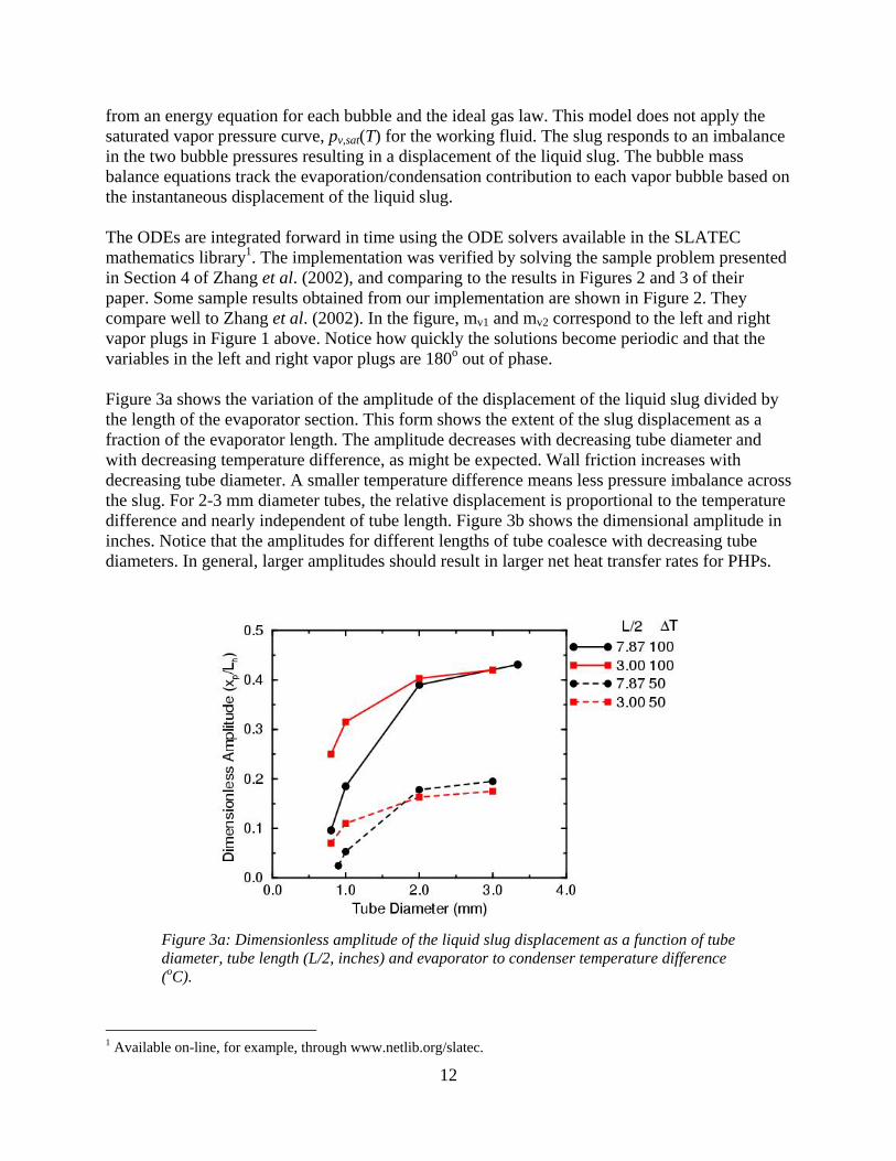
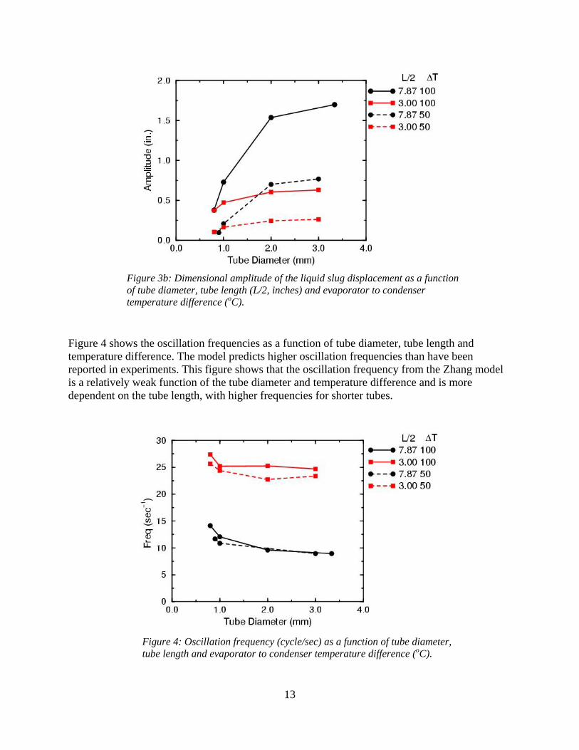
from an energy equation for each bubble and the ideal gas law. This model does not apply the saturated vapor pressure curve, pv,sat(T) for the working fluid. The slug responds to an imbalance in the two bubble pressures resulting in a displacement of the liquid slug. The bubble mass balance equations track the evaporation/condensation contribution to each vapor bubble based on the instantaneous displacement of the liquid slug. The ODEs are integrated forward in time using the ODE solvers available in the SLATEC mathematics library1. The implementation was verified by solving the sample problem presented in Section 4 of Zhang et al. (2002), and comparing to the results in Figures 2 and 3 of their paper. Some sample results obtained from our implementation are shown in Figure 2. They compare well to Zhang et al. (2002). In the figure, mv1 and mv2 correspond to the left and right vapor plugs in Figure 1 above. Notice how quickly the solutions become periodic and that the variables in the left and right vapor plugs are 180o out of phase. Figure 3a shows the variation of the amplitude of the displacement of the liquid slug divided by the length of the evaporator section. This form shows the extent of the slug displacement as a fraction of the evaporator length. The amplitude decreases with decreasing tube diameter and with decreasing temperature difference, as might be expected. Wall friction increases with decreasing tube diameter. A smaller temperature difference means less pressure imbalance across the slug. For 2-3 mm diameter tubes, the relative displacement is proportional to the temperature difference and nearly independent of tube length. Figure 3b shows the dimensional amplitude in inches. Notice that the amplitudes for different lengths of tube coalesce with decreasing tube diameters. In general, larger amplitudes should result in larger net heat transfer rates for PHPs.
1 Available on-line, for example, through www.netlib.org/slatec.
Figure 3a: Dimensionless amplitude of the liquid slug displacement as a function of tube diameter, tube length (L/2, inches) and evaporator to condenser temperature difference (oC).
13
Figure 4 shows the oscillation frequencies as a function of tube diameter, tube length and temperature difference. The model predicts higher oscillation frequencies than have been reported in experiments. This figure shows that the oscillation frequency from the Zhang model is a relatively weak function of the tube diameter and temperature difference and is more dependent on the tube length, with higher frequencies for shorter tubes.
Figure 4: Oscillation frequency (cycle/sec) as a function of tube diameter, tube length and evaporator to condenser temperature difference (oC).
Figure 3b: Dimensional amplitude of the liquid slug displacement as a function of tube diameter, tube length (L/2, inches) and evaporator to condenser temperature difference (oC).
14
Over-Damped Oscillations An interesting observation is that the model admits cases of over-damped oscillation, indicating the motion eventually stops. In general, we find the damped oscillations occur either for sufficiently small values of T/L with a fixed tube diameter, or for sufficiently small tube diameter for fixed T/L. Figure 5 illustrates one such case of displacement history for the conditions for damped oscillations indicated in the caption.
Fig
Table 1. Parameters of the Zhang model which cause damped oscillations
Case Diameter(mm)
L/2 (in.)
T oC
1 1.65 7.87 15 2 0.8 7.87 50 3 0.8 3.00 25
Table 1 documents parameter combinations that correspond to a few cases which exhibit damped oscillations. The table lists the tube diameter, the half-length of the system, L/2 = Lh+Lc as indicated in Figure 1, and the temperature difference between condenser and evaporator. As an example, if the half-length is 7.87 in., and there is a 50 oC temperature difference between the evaporator and condenser, the motion will cease if the tube diameter is only 0.8 mm. If the tube diameter is 1.65 mm, the PHP will not operate with a temperature difference below 15 oC. Case 3 has physical dimensions similar to our application.
Figure 5: Damped oscillations in a 6 inch long (about 3 inches from evaporator to the turn), 0.8 mm diameter U-tube subject to a 25 oC temperature difference between evaporator and condenser.
15
Remarks on the Zhang Model The models developed by Zhang and co-workers include many relevant features of PHPs. They predict oscillation frequencies that appear higher than have been reported. The U-tube model analyzed here predicts conditions for over-damped oscillations; this is a useful design criterion. Further work should include more comparisons with data available in the literature.
CFD MODELS OF PHPs USING FLOW-3D The FLOW-3D CFD Simulator The behavior of PHPs is intriguingly complex, can be chaotic, and is not presently fully-understood. Devising a model that predicts their performance has not been easy and requires some degree of approximation. The discussion that follows identifies the important aspects of a functioning PHP. Each of these aspects must be given consideration when constructing the computational model. First, in order to be a useful device, the “working medium” of a PHP is generally comprised of two fluids: liquid slugs (which behave as an incompressible fluid) intermittent with gas bubbles (compressible phase) confined in a small diameter, continuous tube. Usually, for compactness of the device, this tube may be folded into a tight serpentine configuration with one region of the tube being heated (evaporator) while an opposite region is placed adjacent to a thermal sink. The geometric shape of the folded tube is meant to move heat from one location to another; hence, its name heat pipe. Usually the gas, identified as the compressible phase, is the pure vapor of the liquid phase. Both phases which comprise the “working fluid” of the PHP are discrete; that is, each phase is identifiable and finite in its extent. This is in contrast to other multiphase flows, that are common, where one component is so disperse that the two-phase flow can be modeled as either a mixture or a slight perturbation of single phase flow. This is not the case here. Implied with our description of the physical system for a PHP is the fact that there is a fluid/vapor interface between adjacent phases. This imposes upon any simulation strategy an ability to follow, or track, a (or, in this case, many) free-surface(s). Moreover, wetting characteristics at the moving contact line can influence the dynamics of the working medium. PHPs are most efficient when the liquid/vapor motion is dynamic; this necessitates the need to follow time-dependent, or transient, motion to fully characterize these circulating and sometimes oscillating flows. We believe that mass exchange between liquid and its vapor is an important mechanism that drives motion. For example, a liquid slug/vapor bubble combination in proximity of the evaporator (high temperature side of the PHP) will experience an increase in mass exchange from the liquid to the vapor, thereby causing an increase in pressure within the vapor, expanding its volume, and causing a displacement of the adjacent liquid. Because the entire tube volume is filled with either liquid or its vapor, the kinematics of the entire system are tied together. Motion induced at one location due to, say, evaporator heating will force the entire system to respond. Mass exchange between phases can also lead to changes in the topology of the computational model. Adjacent liquid slugs can coalesce (behavior typical in the vicinity of the condenser region), thereby, absorbing the surrounded vapor; the result is a disappearance of a
16
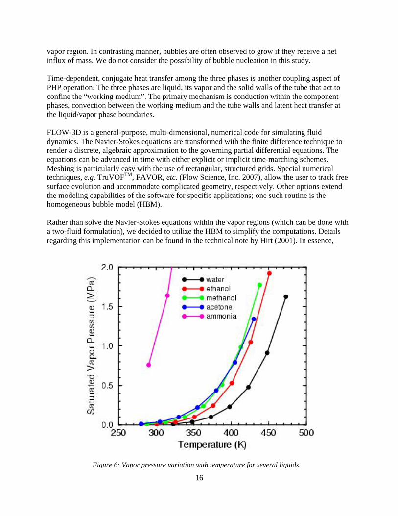
vapor region. In contrasting manner, bubbles are often observed to grow if they receive a net influx of mass. We do not consider the possibility of bubble nucleation in this study. Time-dependent, conjugate heat transfer among the three phases is another coupling aspect of PHP operation. The three phases are liquid, its vapor and the solid walls of the tube that act to confine the “working medium”. The primary mechanism is conduction within the component phases, convection between the working medium and the tube walls and latent heat transfer at the liquid/vapor phase boundaries. FLOW-3D is a general-purpose, multi-dimensional, numerical code for simulating fluid dynamics. The Navier-Stokes equations are transformed with the finite difference technique to render a discrete, algebraic approximation to the governing partial differential equations. The equations can be advanced in time with either explicit or implicit time-marching schemes. Meshing is particularly easy with the use of rectangular, structured grids. Special numerical techniques, e.g. TruVOFTM, FAVOR, etc. (Flow Science, Inc. 2007), allow the user to track free surface evolution and accommodate complicated geometry, respectively. Other options extend the modeling capabilities of the software for specific applications; one such routine is the homogeneous bubble model (HBM). Rather than solve the Navier-Stokes equations within the vapor regions (which can be done with a two-fluid formulation), we decided to utilize the HBM to simplify the computations. Details regarding this implementation can be found in the technical note by Hirt (2001). In essence,
Figure 6: Vapor pressure variation with temperature for several liquids.
17
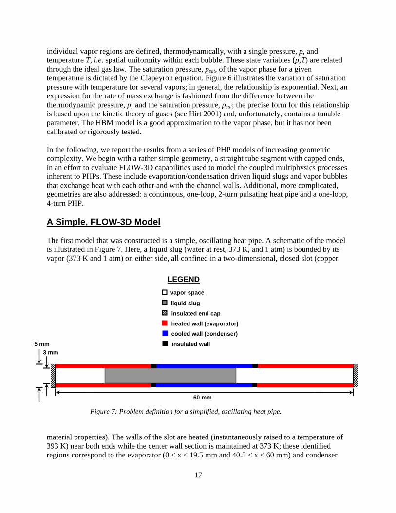
individual vapor regions are defined, thermodynamically, with a single pressure, p, and temperature T, i.e. spatial uniformity within each bubble. These state variables (p,T) are related through the ideal gas law. The saturation pressure, psat, of the vapor phase for a given temperature is dictated by the Clapeyron equation. Figure 6 illustrates the variation of saturation pressure with temperature for several vapors; in general, the relationship is exponential. Next, an expression for the rate of mass exchange is fashioned from the difference between the thermodynamic pressure, p, and the saturation pressure, psat; the precise form for this relationship is based upon the kinetic theory of gases (see Hirt 2001) and, unfortunately, contains a tunable parameter. The HBM model is a good approximation to the vapor phase, but it has not been calibrated or rigorously tested. In the following, we report the results from a series of PHP models of increasing geometric complexity. We begin with a rather simple geometry, a straight tube segment with capped ends, in an effort to evaluate FLOW-3D capabilities used to model the coupled multiphysics processes inherent to PHPs. These include evaporation/condensation driven liquid slugs and vapor bubbles that exchange heat with each other and with the channel walls. Additional, more complicated, geometries are also addressed: a continuous, one-loop, 2-turn pulsating heat pipe and a one-loop, 4-turn PHP. A Simple, FLOW-3D Model The first model that was constructed is a simple, oscillating heat pipe. A schematic of the model is illustrated in Figure 7. Here, a liquid slug (water at rest, 373 K, and 1 atm) is bounded by its vapor (373 K and 1 atm) on either side, all confined in a two-dimensional, closed slot (copper material properties). The walls of the slot are heated (instantaneously raised to a temperature of 393 K) near both ends while the center wall section is maintained at 373 K; these identified regions correspond to the evaporator (0 < x < 19.5 mm and 40.5 < x < 60 mm) and condenser
60 mm
3 mm
5 mm
vapor space
insulated wall
cooled wall (condenser)
heated wall (evaporator)
insulated end cap
liquid slug
LEGEND
Figure 7: Problem definition for a simplified, oscillating heat pipe.
18
(20.5 < x < 39.5 mm) components, respectively. Because the water slug (10 < x < 37 mm) is positioned off-center initially, it will experience a damped [due to wall friction] oscillation as it is first driven and then repelled, in succession, by opposite evaporator regions. The simulation takes into account the following physical phenomena: (i.) fluid motion of the liquid slug, (ii.) heat transfer between liquid and vapor, liquid and walls (hc = 1e6 ergs/cm2/s/K), and vapor and walls (hc = 0.275e6 ergs/cm2/s/K), (iii.) phase change between liquid and vapor (Lv = 2.257e10 ergs/g/K), and (iv.) surface tension (70 dynes/cm @ 90o contact angle at the tri-junction boundaries). The saturation pressure for the vapor is defined in Figure 6 (data for water). Liquid/vapor body forces, i.e. gravity, were neglected for this model. The mesh for this rectangular domain was constructed with uniform, cubic cells of dimension 0.25 mm. This resulted in 4 cells through the thickness of the copper walls and 12 cells through the channel containing the working medium. Total number of cells in the model was 4800. The simulation followed an evolution of the dependent variables (u,v,p,T) for a duration of 120 sec. The model predicts a damped oscillatory motion of the liquid slug, which reveals some insight into the basic mechanisms for PHP operation. One end of the liquid slug is heated as it enters the evaporator section, resulting in an evaporation-driven pressurization of the vapor on this side of the channel which subsequently propels the slug to the other side of the channel. As the heated end of the slug passes the condenser section it gives up its heat to the condenser, thereby cooling and reducing the pressure in the vapor bubble on this side of the device. This cycle is repeated with a period of approximately 7 sec.
Figure 8: Temperature cycling in the left vapor bubble in the simple, oscillating heat pipe.
19
Figure 8 illustrates the time-dependent temperature within the left-side vapor bubble. Results are shown for three different values of the accommodation coefficient, Ac. Recall, that this is an adjustable parameter in the Homogeneous Bubble Model that controls the mass exchange rate at the liquid/vapor interface. Its precise value is difficult to verify. From these results, one can discern the sensitivity of a simple model to the choice of this parameter. The variability is noted, here, but deemed not to be significant. Additional simulations using this single slug model with varying fluid properties (modeling different fluids) and various heat loads produced results consistent with our intuition. These findings build confidence that our model can serve as a useful simulation tool for PHPs. The One-Loop, 2-Turn Model Having demonstrated that the crucial evaporation/condensation motive forces can be modeled, the next example problem that we considered was a continuous, closed-loop configuration. The one-loop geometry offers more degrees of freedom for the fluid motion. Previously, the straight-tube heat pipe only allowed oscillatory motion of the working fluid. The one-loop model is slightly more complex, in that, it allows the possibility of circulatory, or pulsating, flow in addition to any oscillatory motion that might occur. As we demonstrate below, continuous motion is possible for certain problem configurations. Figure 9 is a schematic drawing of the one-loop geometry, showing evaporator and condenser separated by an intervening adiabatic section. The model is limited to two-dimensions2. SolidWorks 2008 was used to generate a solid-model description for the copper walls (inner and outer) which define the one-loop flow channel (3 mm wide). These objects (1 mm copper walls) were imported (via .STL files) into FLOW-3D and superimposed upon the domain of computational cells (3840 total bricks with an average of 6 cells across the flow channel). FLOW-3D does the appropriate interpolation to render the active domain for flow calculations. As the number of computational cells increases, the rendering of the flow domain approaches that described by the original solid model. Liquid slugs (water), defining the original state of priming (initial conditions) for the one-loop model, were also constructed with SolidWorks and imported into the FLOW-3D software. All regions of the flow domain, not identified as liquid slugs, were defined as vapor bubbles. The initial liquid volume fraction was 42%. The evaporator (left end of the flow loop) and condenser (right end of the flow loop) are located along the curves of the flow path. A constant power (0.0065 W) was applied to the evaporator while the condenser was maintained at a fixed temperature (298 K). The model incorporates all those phenomena included in the simple model of the previous section: (i.) fluid motion of the liquid slugs, (ii.) heat transfer between liquid and vapor, liquid and walls (hc = 3e6 ergs/cm2/s/K), and vapor and walls (hc = 0.5e6 ergs/cm2/s/K), (iii.) phase change between liquid and vapor (Lv = 2.257e10 ergs/g/K), and (iv.) surface tension (70 dynes/cm @ 120o contact angle at the tri-junction boundaries). Also included is conjugate heat conduction along the channel walls in the
2 FLOW-3D computational software is inherently three-dimensional (x,y,z). To satisfy this requirement, the discretized model extends for a single cell in the direction normal to the page, in our case, the z-axis. Application of symmetry boundary conditions on model boundaries normal to the z-axis, thus, mimics a two-dimensional simulation.
20
evaporator and adiabatic sections; here adiabatic refers to the fact that heat flow between the outer wall and the environment is not allowed. Gravity was assigned to be 25 cm/sec2 acting in the direction from the condenser to the evaporator. The simulation was executed for 20 sec. Figure 10 illustrates a one-loop, two-phase flow heat pipe in action. The temperature (K) of the walls and liquid phase are plotted in a sequence of simulation snapshots. The time sequence runs between 0.0 sec and 19.85 sec at 0.6 sec intervals. Image sequence is top to bottom (left column), bottom to top (center column) and top to bottom (right column). Initially, there is a sequence of coalescing events. Adjacent liquid slugs are shown to merge in the vicinity of the condenser, behavior that is consistent with one’s intuition. This is not a stable configuration since a body force has been activated in the direction of the evaporator. This establishes the conditions for chaotic fluid motion that is depicted in the remaining simulation snapshots. The full sequence shows an episodic series of oscillations, apparently induced by heating at the evaporator. The general motion depicts a non-equilibrium process of oscillations, slug breakup and coalescence, all induced by the heating and cooling. This irregular behavior is reminiscent of what has been described by other researchers. A variety of exploratory simulations was performed on this flow loop model. In the absence of gravity (i.e., in a horizontal configuration), the simulations indicate that, after a short period of coalescence and reorganization, the liquid prefers to accumulate at the condenser. This behavior has been observed experimentally by other researchers for PHPs with only a few turns (Khandekar & Groll, 2004).
centimeters
cent
imet
ers
evaporator ( q = 0.0065 W)
adiabatic
condenser (298 K)
liquid slug (water)
vapor (homogeneous bubble model)
2D Problem Description
LEGEND
Figure 9: Problem definition of the single-loop heat pipe.
21
Figure 10: A single, closed-loop, two-phase-flow heat pipe in action. Time sequence is between 0.0 sec and 19.85 sec at 0.6 sec intervals. Image sequence is top to bottom (left column), bottom to top (center column) and top to bottom (right column). The evaporator (left end of the flow loop) is heated continuously with time; the condenser (right end of flow loop) is maintained at 298 oK.
22
When a body force is included, directed toward the evaporator, a pulsating mode was established, but only for certain combinations of heating rate and gravity fraction. This meta-stable condition is probably also dependent on other model parameters (flow channel width, thermodynamic properties, etc.). One such state results in a liquid slug shedding event and is depicted in Figure 11. The image sequence spans the time period from 4.4 sec to 5.2 sec at 0.05 sec intervals and should be viewed counter-clockwise from top left. The sequence of mini-figures displays the shedding of smaller liquid slugs from a larger slug as it flows past the turn in the evaporator section. The sequence shows the subsequent coalescence of these smaller slugs to form a larger, but distinct slug. This slug subsequently coalesces with the first slug (near the condenser), to begin the shedding sequence anew. The general motion portrays a meta-stable state in which the evaporative heating is roughly in balance with the gravity-driven drainage of the liquid. Also displayed in each figure is the instantaneous wall temperature (K); the evaporator is clearly identified by its elevated temperature. The One-Loop, 4-Turn Model The one-loop, 4-turn PHP model is a natural extension of the one-loop, 2-turn model discussed in the previous example. The extra two turns impart yet more geometric complexity to the design. This translates into more degrees of freedom for the fluid motion and will lessen the occurrence of stable configurations for which the PHP will “lock”. As we have seen demonstrated, this will happen when the liquid accumulates symmetrically at the condenser and there is no mechanism to dislodge the system from its apparent stable state. We believe, and it has been demonstrated (Ma 2008), that a PHP with more turns performs better than one with fewer turns. This holds true up to a point, when friction losses in the system tend to degrade PHP performance. Figure 12 shows a dimensional sketch of the one-loop, 4-turn PHP showing the actively heated (1e7 ergs/sec/cm3) and cooled regions (-2e6 ergs/sec/cm3) separated by a lengthy adiabatic section. Here, there are two things to note. First, the condenser is on the left side and the evaporator is on the right. Second, the power density supplied to the evaporator as 5 times that of the power density extracted from the condenser. Thus, we expect that the mean temperature of the overall system to rise with time. The width of the flow channel is 2 mm and the copper wall thickness is 1 mm. The accommodation coefficient was chosen to be 5e-5 in an attempt to reduce the effects from liquid/vapor phase change. Gravity was assigned a value of 100 cm/sec2 and is directed from condenser to evaporator. Cell size was 0.04 cm resulting in 5 cells across the flow channel. The simulation was executed for 120 sec. Figure 13 shows a mini figure sequence for early time. The initial configuration of liquid slugs is displayed at time 0.0 sec; regions between the liquid slugs are identified as vapor bubbles. The initial priming of the PHP was intended to approximate a random distribution of liquid slugs and vapor bubbles (all at ambient temperature, 298 K); the liquid fill fraction was roughly 45%. After 17 seconds of operation the liquid/vapor system has rearranged itself into just three liquid slugs separated by vapor bubbles. Notice that most of this coalescing has taken place at, or near, the condenser. However, the configuration is not symmetric and therefore, susceptible to rearrangement. The extra turns exhibited by this device allow, in part, for more chaotic configurations to develop and this leads to improved heat transfer between evaporator and
23
Figure 11: A liquid slug shedding event. Time sequence between 4.4 sec and 5.2 sec at 0.05 sec intervals. Image sequence for this one-loop, 2-turn PHP is counterclockwise from top left.
24
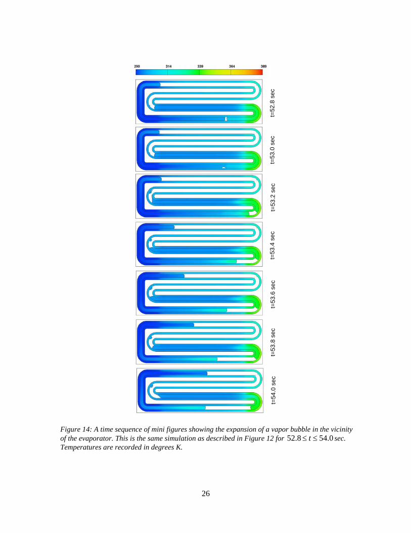
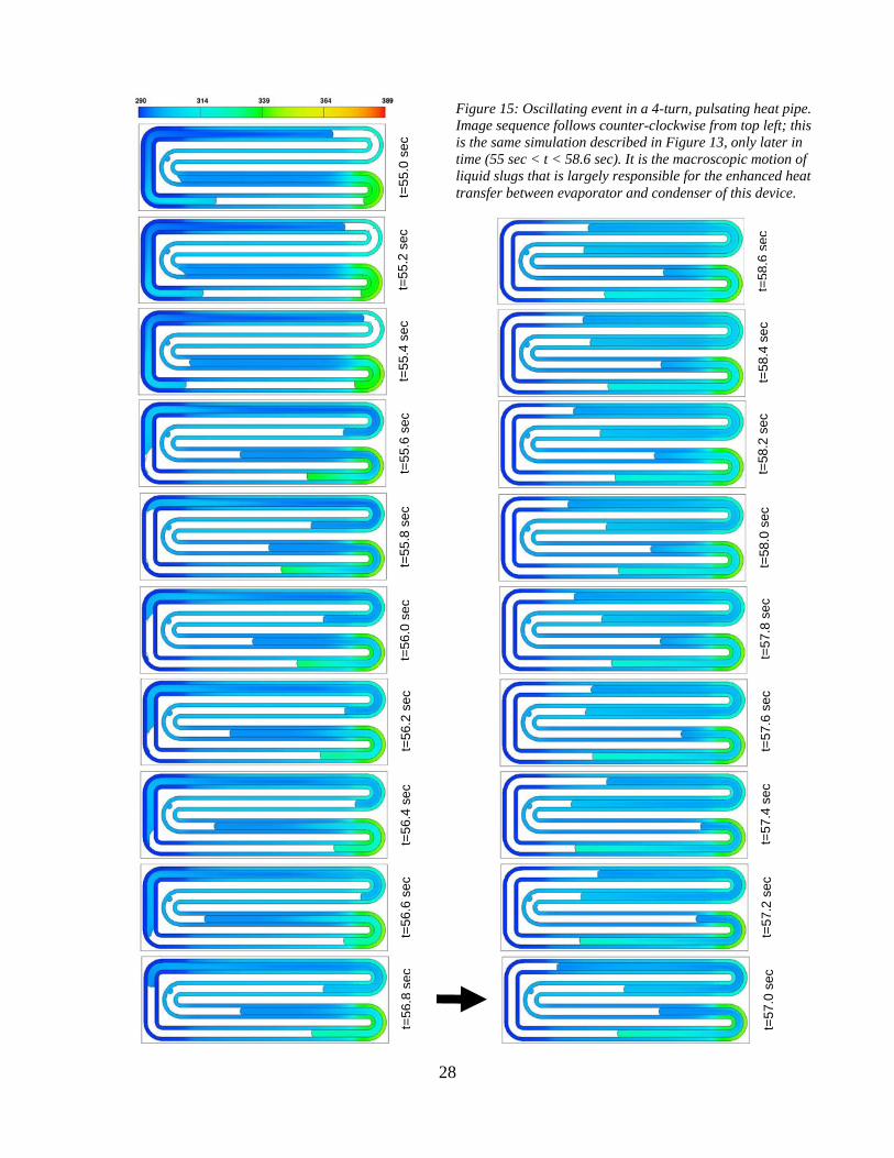
condenser. We can use the results of this simulation to study the mechanisms at work in an active PHP. One such mechanism is illustrated in the time sequence of mini figures between 52.8 sec < t < 54 sec. Figure 14 illustrates the expansion of a vapor bubble in the vicinity of the evaporator. This is not a nucleation event. Rather, it is the result of a small vapor bubble trapped in a relatively cool liquid slug that has been transported into the vicinity of the evaporator. Here, it experiences a rapid rise in temperature causing an increase in bubble pressure. Consequently, it undergoes a volumetric expansion which displaces the neighboring liquid slugs. This sequence of events is recorded in Figure 14 at 0.8 sec intervals. Temperature of the liquid slugs and channel walls is also recorded using a scaled color spectrum in degrees K. Another interesting event is captured in the image sequence (55 sec < t < 58.6 sec) of Figure 15. During this time there is a rapid oscillation of a cool liquid slug past the evaporator. One can witness the exchange of heat between evaporator and the liquid slug. This motion was caused by the bubble expansion event explained with Figure 14. Since all motion in this closed-end PHP is tied together, one can visualize an associated event in the alternate leg of the PHP. Here, a liquid slug that was in the vicinity of the condenser is moved past the evaporator in the other leg. This has a cooling effect on the evaporator. This event is the essence of the PHP and demonstrates a mechanism of substantial heat transfer from evaporator to condenser. Also, comparing channel wall temperatures over the time sequence shows the accumulated heating of channel walls in the adiabatic section. The liquid slugs are also heating up macroscopically over the same time period. In addition to the macroscopic slug motion, the channel walls are being heated by axial
adiabatic section condenser evaporator
Figure 12: Dimensional sketch of the 2-loop, 4-turn pulsating heat pipe showing the actively heated and cooled regions.
5.5 cm
25
heat conduction between evaporator and condenser; both will contribute to macroscopic heat transfer in the device. Heating of channel walls in the adiabatic section offers more surface area for transfer of heat to the liquid slugs. It also suggests a need for efficient heat transfer in the condenser in order to remove the same amount of heat over a smaller surface area. Figure 16 illustrates the configuration state for the one-loop, 4-turn pulsating heat pipe after 2 minutes of simulation time. It appears that this configuration state is, at least momentarily, stable in time; this liquid/vapor arrangement persisted for the final 30 seconds of the simulation. Notice the unequal temperatures that develop in the evaporator legs. This is due to the accumulated history of the fluid motion during PHP operation. Temperatures are again recorded in degrees K. After two minutes of operation the maximum temperature is 389 K, 91 K higher than the initial temperature. The condenser has cooled to a minimum temperature of 290 K, 8 K lower that the initial temperature.
CONCLUDING REMARKS The example problems discussed in this report have demonstrated the ability of the modeling software to simulate various aspects of PHP behavior. While the numerical results have been illustrative and interesting, it is not known whether the predictive behavior is indicative of real, operating PHPs. Code validation is needed to impart confidence to the simulations. Some individual aspects of the FLOW-3D model have been compared to known analytical solutions,
t=0.
0 se
c t=
8.0
sec
t=14
.0 s
ec
t=17
.0 s
ec
Figure 13: Early coalescing of liquid slugs in a 4-turn, pulsating heat pipe. The initial configuration of liquid slugs and adjacent vapor bubbles (all at ambient temperature, 298 K) is shown at top. The liquid fill fraction is approximately 45%. For this simulation the evaporator (right side of device) is heated at five times the rate that the condenser (left side of the device) is cooled. After 17 seconds of operation the liquid/vapor system has re-arranged itself into just three liquid slugs separated by vapor. Notice that most of the coalescing has taken place at, or close to, the condenser. The evaporator ends are nearly equal in temperature (316 K) after 17 seconds of heating at a rate of 107 ergs/cm3/s.
26
t=52
.8 s
ec
t=53
.0 s
ec
t=53
.2 s
ec
t=53
.4 s
ec
t=53
.6 s
ec
t=53
.8 s
ec
t=54
.0 s
ec
Figure 14: A time sequence of mini figures showing the expansion of a vapor bubble in the vicinity of the evaporator. This is the same simulation as described in Figure 12 for 52.8 54.0t sec. Temperatures are recorded in degrees K.
27
but the integrated model has not. It seems that the best we might do is to compare with experimental data – and this is not easy. Little quality data exists for these complicated, multiphase flow devices. And precisely matching initial conditions seems all but impossible. One example of the type of validation that is needed has been mentioned, already, in the report. We noted that the Homogeneous Bubble Phase model uses a scaling coefficient to control the rate of mass exchange between liquid and vapor phases. We do not know how to choose the value of this parameter for a given PHP operating state. Most of the numerical results that we have illustrated have been for, what we considered, a reasonably refined mesh. This determination was based partly on the need to limit the size of the discretized problem because we wanted to march the solution for a reasonable period of time. FLOW-3D results should be verified by performing a systematic grid-refinement study. This exercise would help to determine minimum grid resolution necessary for grid-independent solutions. Another remark is related to validation. We have made an effort to construct a model that contains as much relevant physics as possible and, yet, there are some issues that remain. Some researchers (e.g.Taha and Cui, 2006) have been curious of the thin liquid film that remains on the inside walls of a tube after a vapor bubble has passed. This film can, indeed, be very thin depending upon the liquid viscosity and relative speed of the bubble. Because of the thinness of this liquid film we can never hope to include this feature in a model that includes an entire device. It is believed that these accumulated films contribute significantly to the total evaporation and, hence, the heat transfer rate. With this omission we are compromising the accuracy of the numerical model. We do not know if this is significant. It may be possible to augment the heat transfer coefficient, that we are now using between the vapor regions and the walls, to account for this phenomenon. Our experience with exercising the numerical model has led us to a conclusion shared by other researchers. That is, the efficiency of a PHP, as measured by its ability to transfer heat from evaporator to condenser, is improved by adding more legs (number of turns) to the device. Increasing the geometrical complexity in this manner adds to the degrees of freedom for the flow domain. This, in turn, reduces the tendency of the PHP to find an equilibrium configuration in which the flow ceases. Thus, it seems that more flow connections between evaporator and condenser will improve the device efficiency. We speculate that there is a limit to this notion. At some point, the resistance to flow in a lengthy device will become a debilitating concern.
28
t=58
.4 s
ec
t=58
.6 s
ec
t=58
.2 s
ec
t=58
.0 s
ec
t=57
.8 s
ec
t=57
.6 s
ec
t=57
.4 s
ec
t=57
.2 s
ec
t=57
.0 s
ec
t=56
.4 s
ec
t=56
.2 s
ec
t=56
.0 s
ec
t=55
.8 s
ec
t=55
.6 s
ec
t=55
.4 s
ec
t=55
.2 s
ec
t=55
.0 s
ec
t=56
.6 s
ec
t=56
.8 s
ec
Figure 15: Oscillating event in a 4-turn, pulsating heat pipe. Image sequence follows counter-clockwise from top left; this is the same simulation described in Figure 13, only later in time (55 sec < t < 58.6 sec). It is the macroscopic motion of liquid slugs that is largely responsible for the enhanced heat transfer between evaporator and condenser of this device.
29
REFERENCES
Asai, A., T. Hara, and I. Endo, 1987, One-dimensional model of bubble growth and liquid flow in bubble jet printers, Japanese Journal of Appied Physics, 26(10), 1794-1801.
Dobson, R. T., 2004, Theoretical and experimental modeling of an open oscillatory heat pipe including gravity, International Journal of Thermal Sciences, 43, 113-119.
Flow Science, Inc., 2007, FLOW-3D User Manual, Santa Fe, NM.
Hirt, C. W., 2001, Modeling phase change and homogeneous bubbles, Flow Science Technical Note, FSI-01-TN57.
Khandekar, S. and M. Groll, 2004, An insight into thermo-hydrodynamic coupling in closed-loop pulsating heat pipes, International Journal of Thermal Sciences, 43, 13-20.
Khandekar, S., M. Schneider, P. Schafer, R. Kulenovic, and M. Groll, 2002, Thermofluid dynamic study of flat-plate closed-loop pulsating heat pipes, Microscale Thermophysical Engineering, 6, 303-317.
Khandekar, S., N. Dollinger, and M. Groll, 2003a, Understanding operational regimes of closed loop pulsating heat pipes: an experimental study, Applied Thermal Engineering, 23, 707-719.
Khandekar, S., P. Charoensawan, M. Groll and P. Terdtoon, 2003b, Closed loop pulsating heat pipes Part A: parametric experimental investigations, Applied Thermal Engineering, 23, 2009-2020.
t=12
0se
c
Figure 16: Configuration state for the 4-turn pulsating heat pipe after 2 minutes of simulation time. It appears that this configuration state is, at least momentarily, stable in time; this liquid/vapor arrangement persisted for the final 30 seconds of the simulation. Notice the unequal temperatures that develop in the evaporator legs. This is due to the accumulated history of fluid motion during PHP operation. Temperatures are recoded in degrees K.
30
Khandekar, S., P. Charoensawan, M. Groll and P. Terdtoon, 2003c, Closed loop pulsating heat pipes Part B: visualization and semi-empirical modeling, Applied Thermal Engineering, 23, 2021-2033.
Ma, HB, 2008, private communication.
Ma, HB, C. Wilson, Q. Yu, US Choi and M. Tirumala, 2006a, An experimental investigation of heat transport capacity in a nanofluid oscillating heat pipe, ASME Journal of Heat Transfer, 128, 1213-1216.
Ma, HB, B. Borgmeyer, C. Wilson, H. Park, Q. Yu, M. Tirumala and S. Choi, 2006b, Nanofluid effect on the heat transport capability in an oscillating heat pipe, Applied Physics Letters, 88 (14), 143116(1-3).
Qu, W. and HB Ma, 2007, Theoretical analysis of start-up of a pulsating heat pipe, International Journal of Heat and Mass Transfer, 50, 2309-2316.
Shafii, MB, A Fahgri, and Y. Zhang, 2001, Thermal modeling of unlooped and looped pulsating heat pipes, Journal of Heat Transfer, 123, 1159-1172.
Taha, T. and Z. F. Cui, 2006, CFD Modelling of slug flow inside square capillaries, Chemical Engineering Science, 61, 665-675.
Wilson, C., B. Borgmeyer, RA Winholtz and HB Ma, 2008, Visual observation of oscillating heat pipes using neutron radiography, submitted to AIAA Journal of Thermophysics and Heat Transfer.
Zhang, Y., A. Faghri, 2002, Heat transfer in a pulsating heat pipe with open end, International Journal of Heat and Mass Transfer, 45, 775-764.
Zhang, Y., A. Fahgri, and MB Shaffii, 2002, Analysis of liquid-vapor pulsating flow in a U-shaped miniature tube, International Journal of Heat and Mass Transfer, 45, 2501-2508.
Zhang, Y. and A. Faghri, 2003, Oscillatory flow in PHPs with arbitrary number of turns, Journal of Thermophysics & Heat Transfer, 17(3), 340.
Zhang Y. and A. Faghri, 2008, Advances and unsolved issues in pulsating heat pipes, Heat Transfer Engineering, 29(1), 20-44.
31
Distribution: 1 MS0384 A. C. Ratzel 01500 1 MS0549 M. J. Rightley 05918 1 MS0836 J. S. Lash 01510 1 MS0836 T. L. Aselage 01514 1 MS0836 R. C. Givler 01514 5 MS0836 M. J. Martinez 01514 1 MS0899 Technical Library 09536 1 Dr. Larry Greenberg Northrop Grumman Electronic Systems P.O. Box 1693 MS1105 Baltimore, MD 21203 [email protected] 1 Dr. Steve VanCampen Northrop Grumman Electronic Systems P.O. Box 1521 MS3810 Baltimore, MD 21203 [email protected] 1 Dr. Robert Young Northrop Grumman Electronic Systems P.O. Box 1521 MS3A13 Baltimore, MD 21203 [email protected] 1 Professor Hongbin Ma Department of Mechanical and Aerospace Engineering E3407 Engineering Building East University of Missouri Columbia, MO 65211 [email protected] 1 Dr. Thomas Kenny DARPA/MTO Microsystems Technology Office 3701 N. Fairfax Drive Arlington, VA 22203 [email protected]
32
1 Mary P. Jacobs (electronic copy) Director, Contracts Support Center Micro-Technology and Contracts Group [email protected]


![NANOFLUIDS IN HEAT PIPES - coolingzone · NANOFLUIDS IN HEAT PIPES Figure 1. A Heat Pipe and its Thermal Resistance Network [1] Heat pipes are simple heat transfer devices that are](https://static.documents.pub/doc/80x56/5e1709ba99d6092e366c9a76/nanofluids-in-heat-pipes-nanofluids-in-heat-pipes-figure-1-a-heat-pipe-and-its.jpg)


