JOURNAL OF THEORETICAL AND APPLIED MECHANICS 3, 39, 2001 MODELLING OF FRICTION AND DILATANCY EFFECTS AT BRITTLE INTERFACES FOR MONOTONIC AND CYCLIC LOADING Stanislaw Stupkiewicz Zenon Mróz Institute of Fundamental Technological Research, Polish Academy of Sciences e-mail: [email protected]; [email protected]The most important effects related to monotonic and cyclic response of con- tact interfaces of brittle materials are analyzed in the paper. Next, the availa- ble constitutive models are reviewed with respect to their ability to describe these effects. Several micro-mechanical mechanisms are analyzed including de- cohesion, interaction of primary and secondary asperities, asperity wear and damage and formation of a third body granular layer. Finally, we propose new formulations of constitutive models for cyclic interface response. Keywords: constitutive models, contact interfaces, friction, dilatancy 1. Introduction The problem of modelling of material interface response under monotonic and cyclic loading is of fundamental scientific and engineering importance. In fact, such interfaces occur in most engineering or geotechnical structures such as masonry structures, fibre-reinforced brittle matrix composites, jointed rock masses, dams, bridges, etc. The structural stiffness and limit load are strongly dependent on inelastic interface response. As the displacement discontinuity resulting from frictional slip along interface occurs, the localized effects of damage and wear develop depending on micro-mechanical effects of asperity interaction. A closely related problem of fluid transport along interfaces (es- sential, for instance, in nuclear waste storage technology), essentially coupled with the mechanical response, will not be discussed in the paper. The present paper is devoted to the analysis of monotonic and cyclic effects at contact interfaces of brittle materials. The class of materials (and interfa- ces) is quite wide and includes: rock joints, artificial and natural joints in civil
Transcript
JOURNAL OF THEORETICAL
AND APPLIED MECHANICS
3, 39, 2001
MODELLING OF FRICTION AND DILATANCY EFFECTS
AT BRITTLE INTERFACES FOR MONOTONIC AND CYCLIC
LOADING
Stanisław Stupkiewicz
Zenon Mróz
Institute of Fundamental Technological Research, Polish Academy of Sciences
The most important effects related to monotonic and cyclic response of con-tact interfaces of brittle materials are analyzed in the paper. Next, the availa-ble constitutive models are reviewed with respect to their ability to describethese effects. Several micro-mechanical mechanisms are analyzed including de-cohesion, interaction of primary and secondary asperities, asperity wear anddamage and formation of a third body granular layer. Finally, we propose newformulations of constitutive models for cyclic interface response.
The problem of modelling of material interface response under monotonicand cyclic loading is of fundamental scientific and engineering importance. Infact, such interfaces occur in most engineering or geotechnical structures suchas masonry structures, fibre-reinforced brittle matrix composites, jointed rockmasses, dams, bridges, etc. The structural stiffness and limit load are stronglydependent on inelastic interface response. As the displacement discontinuityresulting from frictional slip along interface occurs, the localized effects ofdamage and wear develop depending on micro-mechanical effects of asperityinteraction. A closely related problem of fluid transport along interfaces (es-sential, for instance, in nuclear waste storage technology), essentially coupledwith the mechanical response, will not be discussed in the paper.The present paper is devoted to the analysis of monotonic and cyclic effects
at contact interfaces of brittle materials. The class of materials (and interfa-ces) is quite wide and includes: rock joints, artificial and natural joints in civil
708 S. Stupkiewicz, Z.Mróz
engineering structures, existing cracks in brittle materials (e.g. concrete, cera-mics), masonry and other cementitious joints, fibre-matrix interfaces in brittlematrix composites, etc. A special attention is paid to interfacial dilatancy phe-nomena as this aspect does not seem to have been sufficiently analyzed in theliterature. Although the emphasis is laid on friction and dilatancy effects, so-me attention is also paid to tensile/compressive behaviour as these phenomenaare coupled and cannot be completely separated.
Some of the interfaces considered in this work are characterized by initialtensile strength. Typical examples of cohesive interfaces are the masonry jointsand fiber-matrix interfaces and also infilled rock joints. The decohesion processis understood as a loss of tensile strength along a predefined interface. Thuscrack propagation problems in which the crack path is a part of the solutionare not considered. This is the case of a weak interface between two dissimilar(or similar) materials. Clearly, the decohesion may occur in tension (mode I),shear (mode II/III) or mixed modes.
In the case of cohesive interfaces, the formation of the actual rough sur-face is a part of the deformation process. As a result, the asperities of onesurface match (at least partially) the asperities of the other surface. On theother hand, most of the non-cohesive interfaces studied in this paper (e.g.rock joints) are generated through the prior cracking processes. In such casethe asperities of both contacting surfaces also match, depending on the me-chanical and environmental conditions since the time of joint formation. Theinteraction of interlocked asperities strongly affects the friction and dilatancyresponse of these interfaces. This, in fact, is a common effect for most of thebrittle interfaces.
In Section 2 the most important effects observed experimentally are pre-sented, followed by a qualitative discussion of the related micro-mechanicalmechanisms. The constitutive models for brittle interfaces are discussed inSection 3. A critical review of existing interface models is provided and somenew formulations of constitutive models of cyclic behaviour of interfaces areproposed.
2. Experimental effects of mechanical interface response
2.1. Typical experimental setups
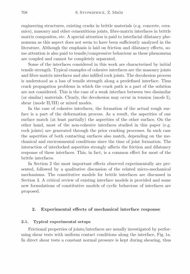
Frictional properties of joints/interfaces are usually investigated by perfor-ming shear tests with uniform contact conditions along the interface, Fig. 1a.In direct shear tests a constant normal pressure is kept during shearing, thus
Modelling of friction and dilatancy effects... 709
allowing for free dilation at the interface. Typically, the friction stress and therelative normal displacement (dilation) are measured as a function of relativetangential displacement (slip). These tests are typically performed for rockjoints, masonry joints, etc., cf for example Bandis et al. (1981), Atkinson etal. (1989).
Fig. 1. Scheme of uniform shearing (a) and tensile/compressive (b) tests on joints
The principle of tensile/compressive tests is similar to that of direct she-aring, Fig. 1b. The measured response is the normal pressure and relativenormal displacement, cf Bandis et al. (1983), van der Pluijm (1997).
The direct shear tests cannot be used for investigation of the propertiesof fiber-matrix interfaces in brittle matrix composites because of very smalldimensions of fibers. Instead, single- or multiple-fiber pulling or pushing testsare usually applied, cf Marshall and Oliver (1990), Marshall et al. (1992).In these tests, however, the contact conditions are not constant along theinterface as the debonding zone and slip zone propagate along the interfacewith increasing load. Unlike in direct shear tests, the normal pressure at theinterface cannot be varied, and also due to the matrix surrounding the fiberthe interfacial dilation is constrained.
Clearly, other types of tests are performed depending on the joint/interfacetype and specific requirements. These, for example, include multiply-jointedrock specimens (Bandis et al., 1981), four point bending tests (van der Pluijm,1997), shearing of masonry wall panels (Anthoine et al., 1995), etc., containingmultiple interface systems.
2.2. Monotonic loading
2.2.1. Tension of cohesive joints
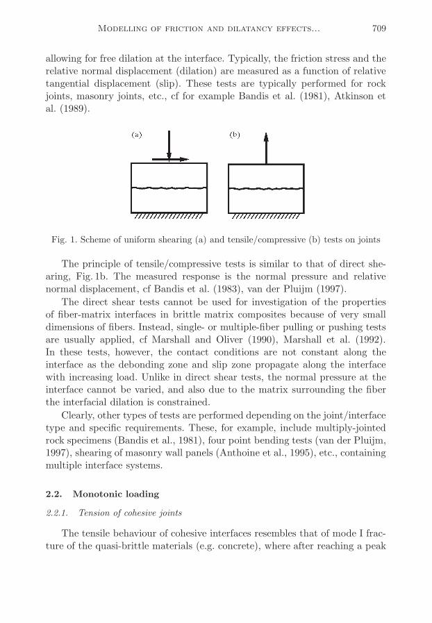
The tensile behaviour of cohesive interfaces resembles that of mode I frac-ture of the quasi-brittle materials (e.g. concrete), where after reaching a peak
710 S. Stupkiewicz, Z.Mróz
the strength decreases to zero, cf Fig. 2 (we use a notation, in which the tensilecontact stresses and opening relative displacements are positive).
Masonry joints are typical examples of cohesive interfaces. Van der Pluijm(1997) investigated the response of masonry bed joints in tension. The frac-ture occurred at the interface between the mortar layer and one of the blocks(bricks). The results were characterized by a large scatter of results in termsof peak stresses, fracture energies and characteristic opening displacements fornominally identical specimens.
Fig. 2. Typical tensile response of cohesive joints
2.2.2. Compression
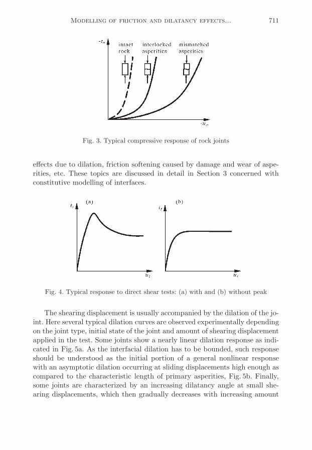
Under compression the relation between the normal pressure and the nor-mal relative displacement is nonlinear. Typical response curves for rock jointsare given in Fig. 3, where two cases are shown namely a joint with interloc-ked (fully mated) asperities and with mismatched asperities, cf Bandis et al.(1983), Sun et al. (1985). When the asperities are not interlocked the contactstiffness decreases as the effect of localized deformation at asperity contacts.
2.2.3. Shearing
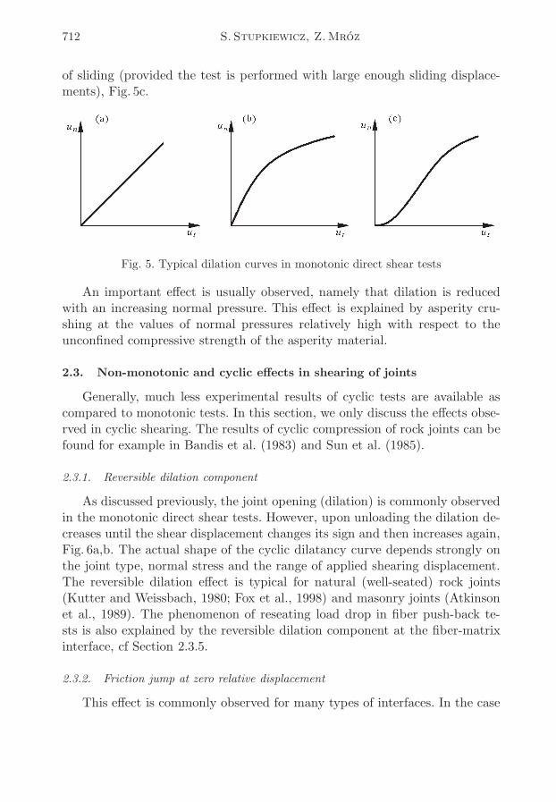
The shearing response under constant normal pressure is usually characte-rized by a peak followed by softening until a residual shear stress is attained,Fig. 4a. This type of behaviour is observed for both cohesive (Atkinson et al.,1989; van der Pluijm, 1993; Binda et al., 1994) and non-cohesive joints (Kut-ter and Weissbach, 1980). In the latter case, the response without the peakshear resistance may also be observed (Bandis et al., 1981; Sun et al., 1985), cfFig. 4b. Generally, the post-peak softening can be attributed to several pheno-mena, often occurring simultaneously, namely to decohesion, configurational
Modelling of friction and dilatancy effects... 711
Fig. 3. Typical compressive response of rock joints
effects due to dilation, friction softening caused by damage and wear of aspe-rities, etc. These topics are discussed in detail in Section 3 concerned withconstitutive modelling of interfaces.
Fig. 4. Typical response to direct shear tests: (a) with and (b) without peak
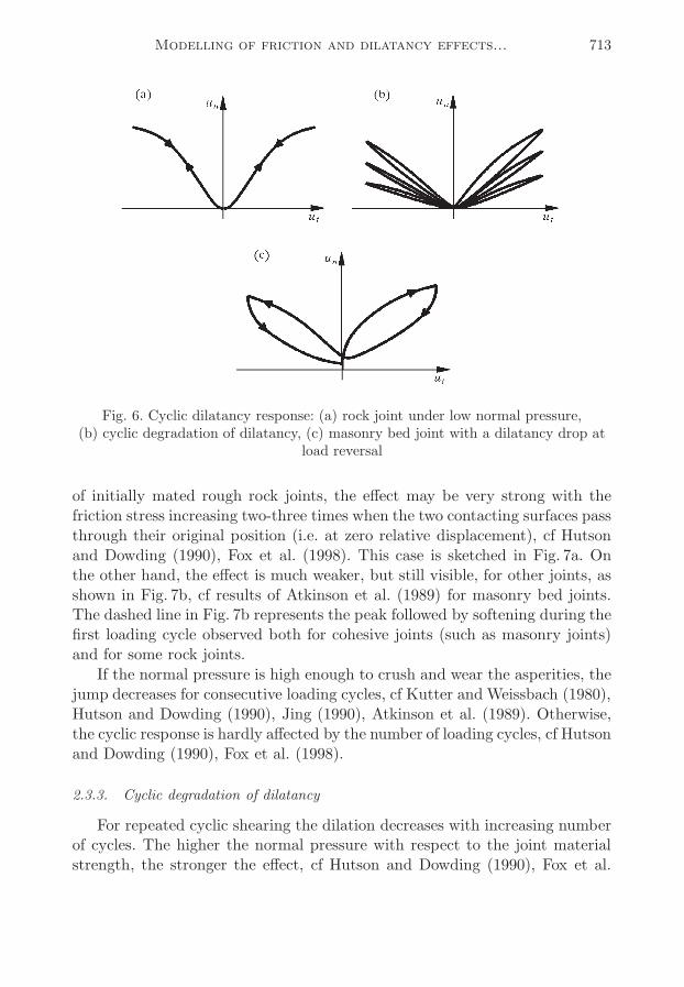
The shearing displacement is usually accompanied by the dilation of the jo-int. Here several typical dilation curves are observed experimentally dependingon the joint type, initial state of the joint and amount of shearing displacementapplied in the test. Some joints show a nearly linear dilation response as indi-cated in Fig. 5a. As the interfacial dilation has to be bounded, such responseshould be understood as the initial portion of a general nonlinear responsewith an asymptotic dilation occurring at sliding displacements high enough ascompared to the characteristic length of primary asperities, Fig. 5b. Finally,some joints are characterized by an increasing dilatancy angle at small she-aring displacements, which then gradually decreases with increasing amount
712 S. Stupkiewicz, Z.Mróz
of sliding (provided the test is performed with large enough sliding displace-ments), Fig. 5c.
Fig. 5. Typical dilation curves in monotonic direct shear tests
An important effect is usually observed, namely that dilation is reducedwith an increasing normal pressure. This effect is explained by asperity cru-shing at the values of normal pressures relatively high with respect to theunconfined compressive strength of the asperity material.
2.3. Non-monotonic and cyclic effects in shearing of joints
Generally, much less experimental results of cyclic tests are available ascompared to monotonic tests. In this section, we only discuss the effects obse-rved in cyclic shearing. The results of cyclic compression of rock joints can befound for example in Bandis et al. (1983) and Sun et al. (1985).
2.3.1. Reversible dilation component
As discussed previously, the joint opening (dilation) is commonly observedin the monotonic direct shear tests. However, upon unloading the dilation de-creases until the shear displacement changes its sign and then increases again,Fig. 6a,b. The actual shape of the cyclic dilatancy curve depends strongly onthe joint type, normal stress and the range of applied shearing displacement.The reversible dilation effect is typical for natural (well-seated) rock joints(Kutter and Weissbach, 1980; Fox et al., 1998) and masonry joints (Atkinsonet al., 1989). The phenomenon of reseating load drop in fiber push-back te-sts is also explained by the reversible dilation component at the fiber-matrixinterface, cf Section 2.3.5.
2.3.2. Friction jump at zero relative displacement
This effect is commonly observed for many types of interfaces. In the case
Modelling of friction and dilatancy effects... 713
Fig. 6. Cyclic dilatancy response: (a) rock joint under low normal pressure,(b) cyclic degradation of dilatancy, (c) masonry bed joint with a dilatancy drop at
load reversal
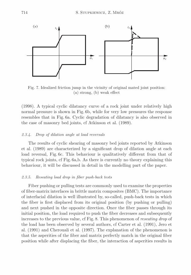
of initially mated rough rock joints, the effect may be very strong with thefriction stress increasing two-three times when the two contacting surfaces passthrough their original position (i.e. at zero relative displacement), cf Hutsonand Dowding (1990), Fox et al. (1998). This case is sketched in Fig. 7a. Onthe other hand, the effect is much weaker, but still visible, for other joints, asshown in Fig. 7b, cf results of Atkinson et al. (1989) for masonry bed joints.The dashed line in Fig. 7b represents the peak followed by softening during thefirst loading cycle observed both for cohesive joints (such as masonry joints)and for some rock joints.
If the normal pressure is high enough to crush and wear the asperities, thejump decreases for consecutive loading cycles, cf Kutter and Weissbach (1980),Hutson and Dowding (1990), Jing (1990), Atkinson et al. (1989). Otherwise,the cyclic response is hardly affected by the number of loading cycles, cf Hutsonand Dowding (1990), Fox et al. (1998).
2.3.3. Cyclic degradation of dilatancy
For repeated cyclic shearing the dilation decreases with increasing numberof cycles. The higher the normal pressure with respect to the joint materialstrength, the stronger the effect, cf Hutson and Dowding (1990), Fox et al.
714 S. Stupkiewicz, Z.Mróz
Fig. 7. Idealized friction jump in the vicinity of original mated joint position:(a) strong, (b) weak effect
(1998). A typical cyclic dilatancy curve of a rock joint under relatively highnormal pressure is shown in Fig. 6b, while for very low pressures the responseresembles that in Fig. 6a. Cyclic degradation of dilatancy is also observed inthe case of masonry bed joints, cf Atkinson et al. (1989).
2.3.4. Drop of dilation angle at load reversals
The results of cyclic shearing of masonry bed joints reported by Atkinsonet al. (1989) are characterized by a significant drop of dilation angle at eachload reversal, Fig. 6c. This behaviour is qualitatively different from that oftypical rock joints, cf Fig. 6a,b. As there is currently no theory explaining thisbehaviour, it will be discussed in detail in the modelling part of the paper.
2.3.5. Reseating load drop in fiber push-back tests
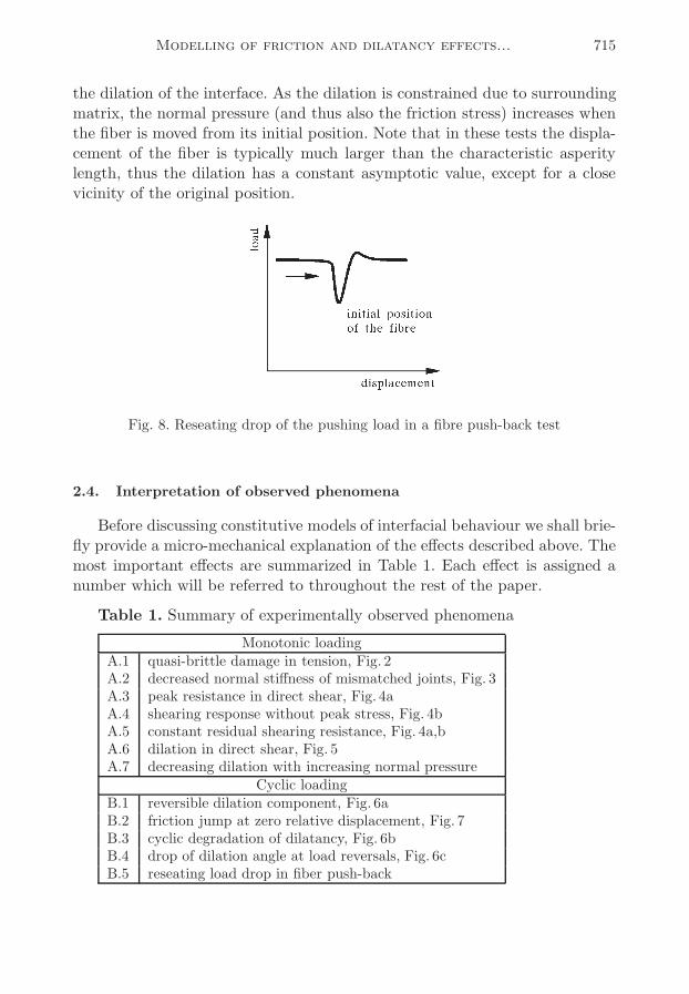
Fiber pushing or pulling tests are commonly used to examine the propertiesof fiber-matrix interfaces in brittle matrix composites (BMC). The importanceof interfacial dilation is well illustrated by, so-called, push-back tests in whichthe fiber is first displaced from its original position (by pushing or pulling)and next pushed in the opposite direction. Once the fiber passes through itsinitial position, the load required to push the fiber decreases and subsequentlyincreases to the previous value, cf Fig. 8. This phenomenon of reseating drop ofthe load has been observed by several authors, cf Carter et al. (1991), Jero etal. (1991) and Cherouali et al. (1997). The explanation of the phenomenon isthat the asperities of the fiber and matrix perfectly match in the original fiberposition while after displacing the fiber, the interaction of asperities results in
Modelling of friction and dilatancy effects... 715
the dilation of the interface. As the dilation is constrained due to surroundingmatrix, the normal pressure (and thus also the friction stress) increases whenthe fiber is moved from its initial position. Note that in these tests the displa-cement of the fiber is typically much larger than the characteristic asperitylength, thus the dilation has a constant asymptotic value, except for a closevicinity of the original position.
Fig. 8. Reseating drop of the pushing load in a fibre push-back test
2.4. Interpretation of observed phenomena
Before discussing constitutive models of interfacial behaviour we shall brie-fly provide a micro-mechanical explanation of the effects described above. Themost important effects are summarized in Table 1. Each effect is assigned anumber which will be referred to throughout the rest of the paper.
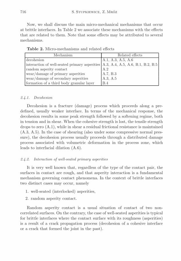
Table 1. Summary of experimentally observed phenomena
Monotonic loadingA.1 quasi-brittle damage in tension, Fig. 2A.2 decreased normal stiffness of mismatched joints, Fig. 3A.3 peak resistance in direct shear, Fig. 4aA.4 shearing response without peak stress, Fig. 4bA.5 constant residual shearing resistance, Fig. 4a,bA.6 dilation in direct shear, Fig. 5A.7 decreasing dilation with increasing normal pressure
Cyclic loadingB.1 reversible dilation component, Fig. 6aB.2 friction jump at zero relative displacement, Fig. 7B.3 cyclic degradation of dilatancy, Fig. 6bB.4 drop of dilation angle at load reversals, Fig. 6cB.5 reseating load drop in fiber push-back
716 S. Stupkiewicz, Z.Mróz
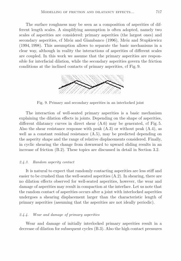
Now, we shall discuss the main micro-mechanical mechanisms that occurat brittle interfaces. In Table 2 we associate these mechanisms with the effectsthat are related to them. Note that some effects may be attributed to severalmechanisms.
Table 2. Micro-mechanisms and related effects
Mechanism Related effectsdecohesion A.1, A.3, A.5, A.6interaction of well-seated primary asperities A.3, A.4, A.5, A.6, B.1, B.2, B.5random asperity contact A.2wear/damage of primary asperities A.7, B.3wear/damage of secondary asperities A.3, A.5formation of a third body granular layer B.4
2.4.1. Decohesion
Decohesion is a fracture (damage) process which proceeds along a pre-defined, usually weaker interface. In terms of the mechanical response, thedecohesion results in some peak strength followed by a softening regime, bothin tension and in shear. When the cohesive strength is lost, the tensile strengthdrops to zero (A.1), while in shear a residual frictional resistance is maintained(A.3, A.5). In the case of shearing (also under some compressive normal pres-sure), the decohesion process usually proceeds through a distributed damageprocess associated with volumetric deformation in the process zone, whichleads to interfacial dilation (A.6).
2.4.2. Interaction of well-seated primary asperities
It is very well known that, regardless of the type of the contact pair, thesurfaces in contact are rough, and that asperity interaction is a fundamentalmechanism governing contact phenomena. In the context of brittle interfacestwo distinct cases may occur, namely
1. well-seated (interlocked) asperities,
2. random asperity contact.
Random asperity contact is a usual situation of contact of two non-correlated surfaces. On the contrary, the case of well-seated asperities is typicalfor brittle interfaces where the contact surface with its roughness (asperities)is a result of a crack propagation process (decohesion of a cohesive interfaceor a crack that formed the joint in the past).
Modelling of friction and dilatancy effects... 717
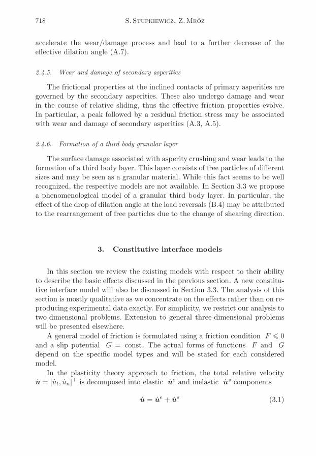
The surface roughness may be seen as a composition of asperities of dif-ferent length scales. A simplifying assumption is often adopted, namely twoscales of asperities are considered: primary asperities (the largest ones) andsecondary asperities, cf Mróz and Giambanco (1996), Mróz and Stupkiewicz(1994, 1998). This assumption allows to separate the basic mechanisms in aclear way, although in reality the interactions of asperities of different scalesare coupled. In this work we assume that the primary asperities are respon-sible for interfacial dilation, while the secondary asperities govern the frictionconditions at the inclined contacts of primary asperities, cf Fig. 9.
Fig. 9. Primary and secondary asperities in an interlocked joint
The interaction of well-seated primary asperities is a basic mechanismexplaining the dilation effects in joints. Depending on the shape of asperities,different dilatancy curves in direct shear (A.6) may be generated, cf Fig. 5.Also the shear resistance response with peak (A.3) or without peak (A.4), aswell as a constant residual resistance (A.5), may be predicted depending onthe asperity shape and the range of relative displacements considered. Finally,in cyclic shearing the change from downward to upward sliding results in anincrease of friction (B.2). These topics are discussed in detail in Section 3.2.
2.4.3. Random asperity contact
It is natural to expect that randomly contacting asperities are less stiff andeasier to be crushed than the well-seated asperities (A.2). In shearing, there areno dilation effects observed for well-seated asperities, however, the wear anddamage of asperities may result in compaction at the interface. Let us note thatthe random contact of asperities occurs after a joint with interlocked asperitiesundergoes a shearing displacement larger than the characteristic length ofprimary asperities (assuming that the asperities are not ideally periodic).
2.4.4. Wear and damage of primary asperities
Wear and damage of initially interlocked primary asperities result in adecrease of dilation for subsequent cycles (B.3). Also the high contact pressures
718 S. Stupkiewicz, Z.Mróz
accelerate the wear/damage process and lead to a further decrease of theeffective dilation angle (A.7).
2.4.5. Wear and damage of secondary asperities
The frictional properties at the inclined contacts of primary asperities aregoverned by the secondary asperities. These also undergo damage and wearin the course of relative sliding, thus the effective friction properties evolve.In particular, a peak followed by a residual friction stress may be associatedwith wear and damage of secondary asperities (A.3, A.5).
2.4.6. Formation of a third body granular layer
The surface damage associated with asperity crushing and wear leads to theformation of a third body layer. This layer consists of free particles of differentsizes and may be seen as a granular material. While this fact seems to be wellrecognized, the respective models are not available. In Section 3.3 we proposea phenomenological model of a granular third body layer. In particular, theeffect of the drop of dilation angle at the load reversals (B.4) may be attributedto the rearrangement of free particles due to the change of shearing direction.
3. Constitutive interface models
In this section we review the existing models with respect to their abilityto describe the basic effects discussed in the previous section. A new constitu-tive interface model will also be discussed in Section 3.3. The analysis of thissection is mostly qualitative as we concentrate on the effects rather than on re-producing experimental data exactly. For simplicity, we restrict our analysis totwo-dimensional problems. Extension to general three-dimensional problemswill be presented elsewhere.
A general model of friction is formulated using a friction condition F ¬ 0and a slip potential G = const . The actual forms of functions F and Gdepend on the specific model types and will be stated for each consideredmodel.
In the plasticity theory approach to friction, the total relative velocityu = [ut, un]
⊤ is decomposed into elastic ue and inelastic us components
u = ue + us (3.1)
Modelling of friction and dilatancy effects... 719
and the rate of contact traction t = [tt, tn]⊤ is related to the elastic velocity
component by the rule
t = Due D =
[kt 00 kn
](3.2)
where kn, kt are the normal and tangential contact stiffness parameters, whichmay generally depend on contact stresses and the respective state variables.The slip potential G = const generates the following slip rule
us = λ
∂G
∂tλ 0 λF = 0 (3.3)
where λ is a plastic multiplier.
3.1. Coulomb-type laws
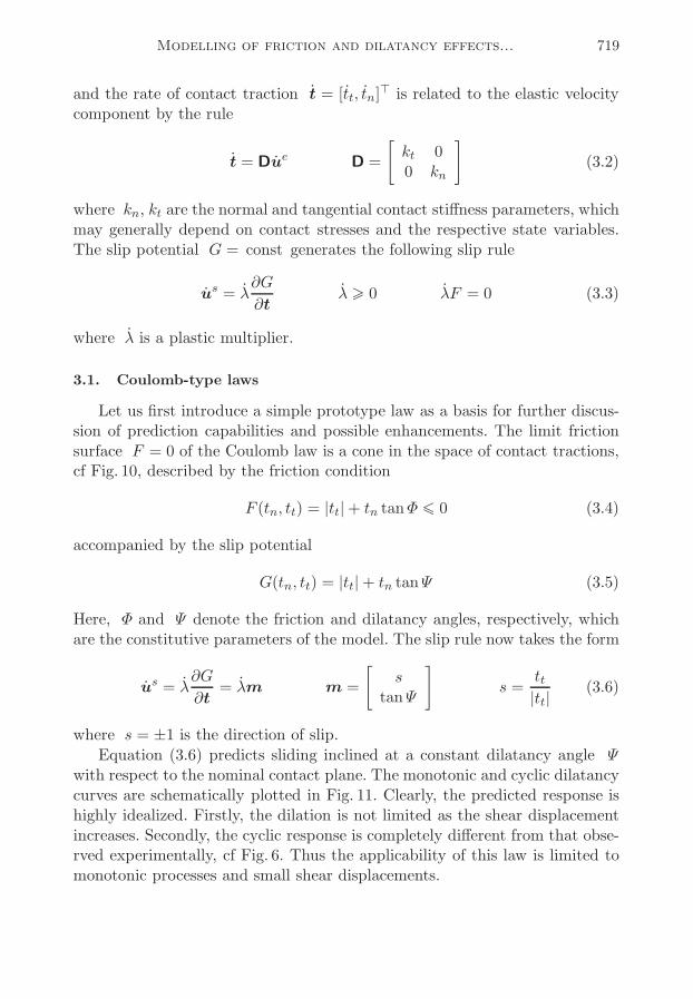
Let us first introduce a simple prototype law as a basis for further discus-sion of prediction capabilities and possible enhancements. The limit frictionsurface F = 0 of the Coulomb law is a cone in the space of contact tractions,cf Fig. 10, described by the friction condition
F (tn, tt) = |tt|+ tn tanΦ ¬ 0 (3.4)
accompanied by the slip potential
G(tn, tt) = |tt|+ tn tanΨ (3.5)
Here, Φ and Ψ denote the friction and dilatancy angles, respectively, whichare the constitutive parameters of the model. The slip rule now takes the form
us = λ
∂G
∂t= λm m =
[stanΨ
]s =tt|tt|
(3.6)
where s = ±1 is the direction of slip.
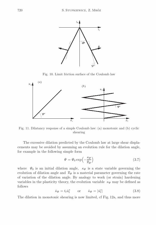
Equation (3.6) predicts sliding inclined at a constant dilatancy angle Ψwith respect to the nominal contact plane. The monotonic and cyclic dilatancycurves are schematically plotted in Fig. 11. Clearly, the predicted response ishighly idealized. Firstly, the dilation is not limited as the shear displacementincreases. Secondly, the cyclic response is completely different from that obse-rved experimentally, cf Fig. 6. Thus the applicability of this law is limited tomonotonic processes and small shear displacements.
720 S. Stupkiewicz, Z.Mróz
Fig. 10. Limit friction surface of the Coulomb law
Fig. 11. Dilatancy response of a simple Coulomb law: (a) monotonic and (b) cyclicshearing
The excessive dilation predicted by the Coulomb law at large shear displa-cements may be avoided by assuming an evolution rule for the dilation angle,for example in the following simple form
Ψ = Ψ0 exp(−κΨκΨ
)(3.7)
where Ψ0 is an initial dilation angle, κΨ is a state variable governing theevolution of dilation angle and κΨ is a material parameter governing the rateof variation of the dilation angle. By analogy to work (or strain) hardeningvariables in the plasticity theory, the evolution variable κΨ may be defined asfollows
κΨ = ttust or κΨ = |u
st | (3.8)
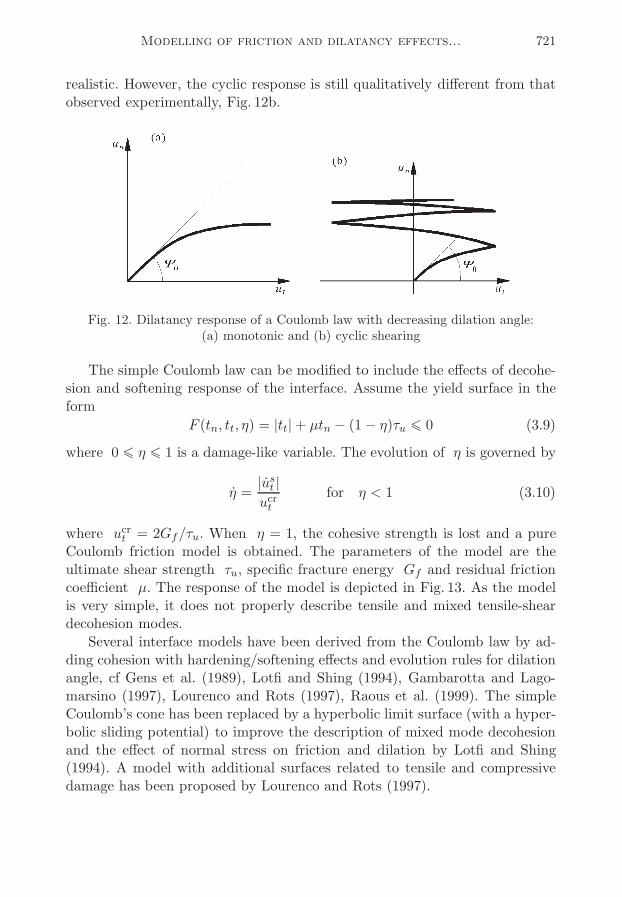
The dilation in monotonic shearing is now limited, cf Fig. 12a, and thus more
Modelling of friction and dilatancy effects... 721
realistic. However, the cyclic response is still qualitatively different from thatobserved experimentally, Fig. 12b.
Fig. 12. Dilatancy response of a Coulomb law with decreasing dilation angle:(a) monotonic and (b) cyclic shearing
The simple Coulomb law can be modified to include the effects of decohe-sion and softening response of the interface. Assume the yield surface in theform
F (tn, tt, η) = |tt|+ µtn − (1− η)τu ¬ 0 (3.9)
where 0 ¬ η ¬ 1 is a damage-like variable. The evolution of η is governed by
η =|ust |
ucrtfor η < 1 (3.10)
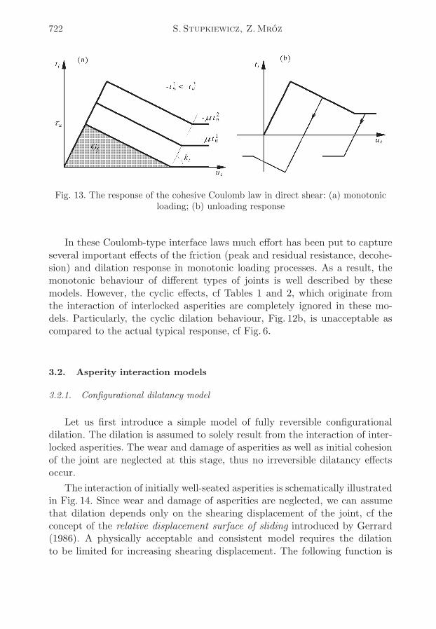
where ucrt = 2Gf/τu. When η = 1, the cohesive strength is lost and a pureCoulomb friction model is obtained. The parameters of the model are theultimate shear strength τu, specific fracture energy Gf and residual frictioncoefficient µ. The response of the model is depicted in Fig. 13. As the modelis very simple, it does not properly describe tensile and mixed tensile-sheardecohesion modes.
Several interface models have been derived from the Coulomb law by ad-ding cohesion with hardening/softening effects and evolution rules for dilationangle, cf Gens et al. (1989), Lotfi and Shing (1994), Gambarotta and Lago-marsino (1997), Lourenco and Rots (1997), Raous et al. (1999). The simpleCoulomb’s cone has been replaced by a hyperbolic limit surface (with a hyper-bolic sliding potential) to improve the description of mixed mode decohesionand the effect of normal stress on friction and dilation by Lotfi and Shing(1994). A model with additional surfaces related to tensile and compressivedamage has been proposed by Lourenco and Rots (1997).
722 S. Stupkiewicz, Z.Mróz
Fig. 13. The response of the cohesive Coulomb law in direct shear: (a) monotonicloading; (b) unloading response
In these Coulomb-type interface laws much effort has been put to captureseveral important effects of the friction (peak and residual resistance, decohe-sion) and dilation response in monotonic loading processes. As a result, themonotonic behaviour of different types of joints is well described by thesemodels. However, the cyclic effects, cf Tables 1 and 2, which originate fromthe interaction of interlocked asperities are completely ignored in these mo-dels. Particularly, the cyclic dilation behaviour, Fig. 12b, is unacceptable ascompared to the actual typical response, cf Fig. 6.
3.2. Asperity interaction models
3.2.1. Configurational dilatancy model
Let us first introduce a simple model of fully reversible configurationaldilation. The dilation is assumed to solely result from the interaction of inter-locked asperities. The wear and damage of asperities as well as initial cohesionof the joint are neglected at this stage, thus no irreversible dilatancy effectsoccur.
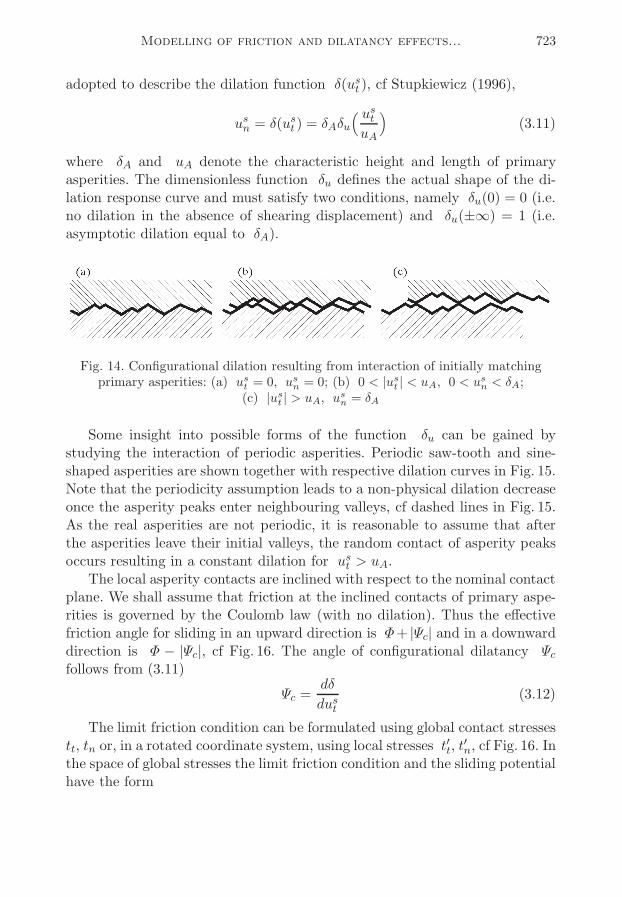
The interaction of initially well-seated asperities is schematically illustratedin Fig. 14. Since wear and damage of asperities are neglected, we can assumethat dilation depends only on the shearing displacement of the joint, cf theconcept of the relative displacement surface of sliding introduced by Gerrard(1986). A physically acceptable and consistent model requires the dilationto be limited for increasing shearing displacement. The following function is
Modelling of friction and dilatancy effects... 723
adopted to describe the dilation function δ(ust ), cf Stupkiewicz (1996),
usn = δ(ust ) = δAδu
( ustuA
)(3.11)
where δA and uA denote the characteristic height and length of primaryasperities. The dimensionless function δu defines the actual shape of the di-lation response curve and must satisfy two conditions, namely δu(0) = 0 (i.e.no dilation in the absence of shearing displacement) and δu(±∞) = 1 (i.e.asymptotic dilation equal to δA).
Fig. 14. Configurational dilation resulting from interaction of initially matchingprimary asperities: (a) ust = 0, u
sn = 0; (b) 0 < |u
st | < uA, 0 < u
sn < δA;
(c) |ust | > uA, usn = δA
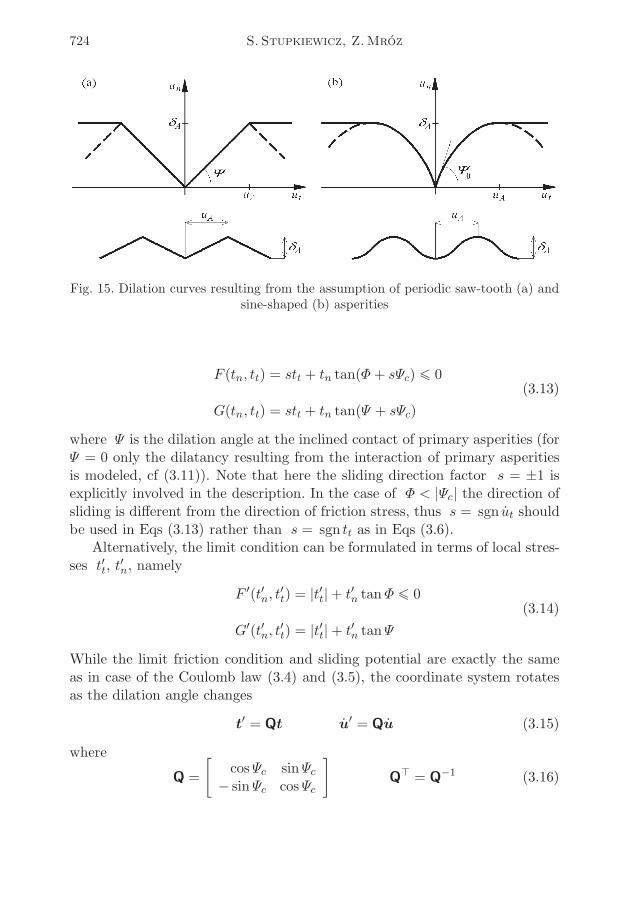
Some insight into possible forms of the function δu can be gained bystudying the interaction of periodic asperities. Periodic saw-tooth and sine-shaped asperities are shown together with respective dilation curves in Fig. 15.Note that the periodicity assumption leads to a non-physical dilation decreaseonce the asperity peaks enter neighbouring valleys, cf dashed lines in Fig. 15.As the real asperities are not periodic, it is reasonable to assume that afterthe asperities leave their initial valleys, the random contact of asperity peaksoccurs resulting in a constant dilation for ust > uA.The local asperity contacts are inclined with respect to the nominal contact
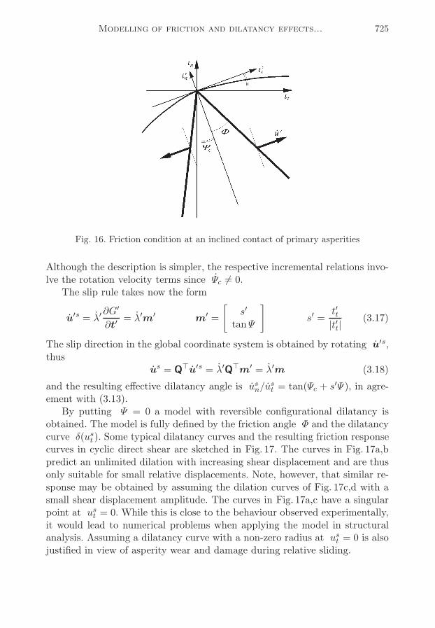
plane. We shall assume that friction at the inclined contacts of primary aspe-rities is governed by the Coulomb law (with no dilation). Thus the effectivefriction angle for sliding in an upward direction is Φ+ |Ψc| and in a downwarddirection is Φ − |Ψc|, cf Fig. 16. The angle of configurational dilatancy Ψcfollows from (3.11)
Ψc =dδ
dust(3.12)
The limit friction condition can be formulated using global contact stressestt, tn or, in a rotated coordinate system, using local stresses t
′t, t′n, cf Fig. 16. In
the space of global stresses the limit friction condition and the sliding potentialhave the form
724 S. Stupkiewicz, Z.Mróz
Fig. 15. Dilation curves resulting from the assumption of periodic saw-tooth (a) andsine-shaped (b) asperities
F (tn, tt) = stt + tn tan(Φ+ sΨc) ¬ 0(3.13)
G(tn, tt) = stt + tn tan(Ψ + sΨc)
where Ψ is the dilation angle at the inclined contact of primary asperities (forΨ = 0 only the dilatancy resulting from the interaction of primary asperitiesis modeled, cf (3.11)). Note that here the sliding direction factor s = ±1 isexplicitly involved in the description. In the case of Φ < |Ψc| the direction ofsliding is different from the direction of friction stress, thus s = sgn ut shouldbe used in Eqs (3.13) rather than s = sgn tt as in Eqs (3.6).Alternatively, the limit condition can be formulated in terms of local stres-
ses t′t, t′n, namely
F ′(t′n, t′
t) = |t′
t|+ t′
n tanΦ ¬ 0(3.14)
G′(t′n, t′
t) = |t′
t|+ t′
n tanΨ
While the limit friction condition and sliding potential are exactly the sameas in case of the Coulomb law (3.4) and (3.5), the coordinate system rotatesas the dilation angle changes
t′ = Qt u
′ = Qu (3.15)
where
Q =
[cosΨc sinΨc− sinΨc cosΨc
]Q⊤ = Q−1 (3.16)
Modelling of friction and dilatancy effects... 725
Fig. 16. Friction condition at an inclined contact of primary asperities
Although the description is simpler, the respective incremental relations invo-lve the rotation velocity terms since Ψc 6= 0.The slip rule takes now the form
u′s = λ′
∂G′
∂t′= λ′m′ m
′ =
[s′
tanΨ
]s′ =
t′t|t′t|
(3.17)
The slip direction in the global coordinate system is obtained by rotating u′s,thus
us = Q⊤u′s = λ′Q⊤m′ = λ′m (3.18)
and the resulting effective dilatancy angle is usn/ust = tan(Ψc + s
′Ψ), in agre-ement with (3.13).By putting Ψ = 0 a model with reversible configurational dilatancy is
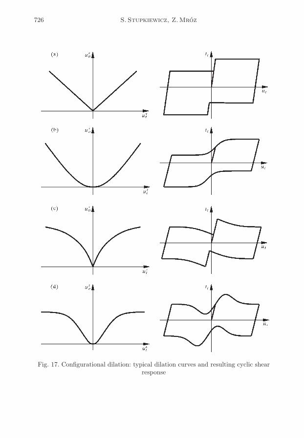
obtained. The model is fully defined by the friction angle Φ and the dilatancycurve δ(ust ). Some typical dilatancy curves and the resulting friction responsecurves in cyclic direct shear are sketched in Fig. 17. The curves in Fig. 17a,bpredict an unlimited dilation with increasing shear displacement and are thusonly suitable for small relative displacements. Note, however, that similar re-sponse may be obtained by assuming the dilation curves of Fig. 17c,d with asmall shear displacement amplitude. The curves in Fig. 17a,c have a singularpoint at ust = 0. While this is close to the behaviour observed experimentally,it would lead to numerical problems when applying the model in structuralanalysis. Assuming a dilatancy curve with a non-zero radius at ust = 0 is alsojustified in view of asperity wear and damage during relative sliding.
Modelling of friction and dilatancy effects... 727
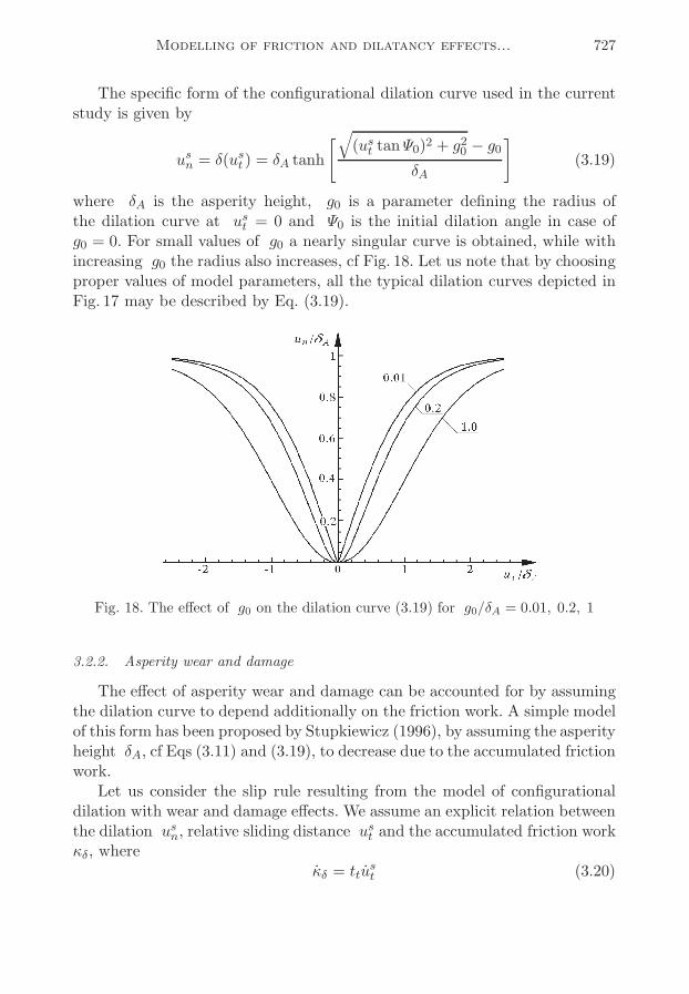
The specific form of the configurational dilation curve used in the currentstudy is given by
usn = δ(ust ) = δA tanh
[√(ust tanΨ0)
2 + g20 − g0
δA
](3.19)
where δA is the asperity height, g0 is a parameter defining the radius ofthe dilation curve at ust = 0 and Ψ0 is the initial dilation angle in case ofg0 = 0. For small values of g0 a nearly singular curve is obtained, while withincreasing g0 the radius also increases, cf Fig. 18. Let us note that by choosingproper values of model parameters, all the typical dilation curves depicted inFig. 17 may be described by Eq. (3.19).
Fig. 18. The effect of g0 on the dilation curve (3.19) for g0/δA = 0.01, 0.2, 1
3.2.2. Asperity wear and damage
The effect of asperity wear and damage can be accounted for by assumingthe dilation curve to depend additionally on the friction work. A simple modelof this form has been proposed by Stupkiewicz (1996), by assuming the asperityheight δA, cf Eqs (3.11) and (3.19), to decrease due to the accumulated frictionwork.Let us consider the slip rule resulting from the model of configurational
dilation with wear and damage effects. We assume an explicit relation betweenthe dilation usn, relative sliding distance u
st and the accumulated friction work
κδ, whereκδ = ttu
st (3.20)
728 S. Stupkiewicz, Z.Mróz
Note that other variables governing the wear effects may also be used, e.g.κδ = ttu
st + tnu
sn or κδ = t
′tu′ts. By taking the time derivative of the relation
usn = δ(ust , κδ) we have
usn =∂δ
∂ustust +
∂δ
∂κδκδ = tanΨcu
st +∂δ
∂κδttust =
(3.21)
=[tanΨc − s
∂δ
∂κδtn tan(Φ+ sΨc)
]ust
where the limit friction condition (3.13)1 has also been used. Thus in additionto the configurational dilation there is a compaction term resulting from wear.With increasing normal pressure this additional term increases and the dilationis reduced, cf effect A.7 in Table 1.
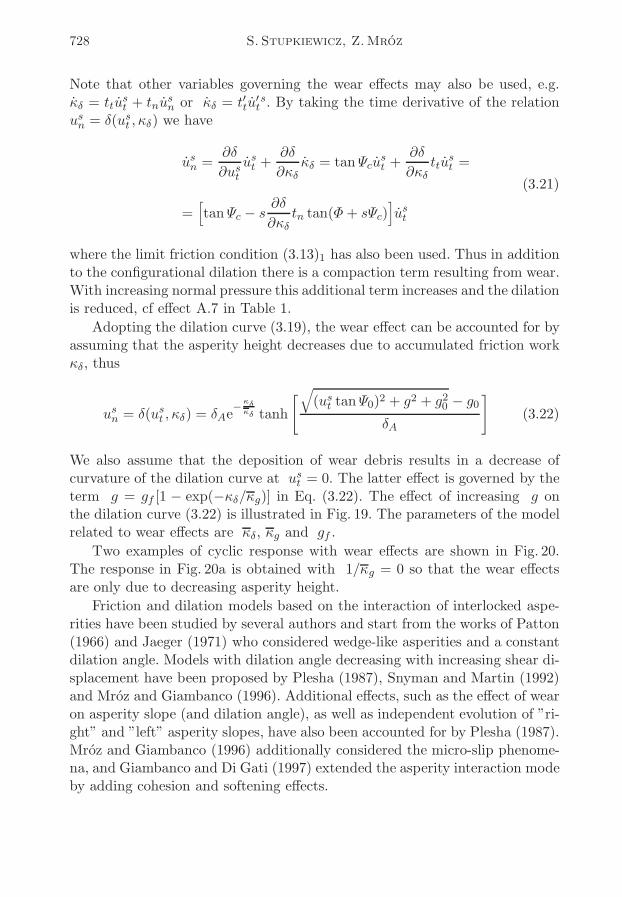
Adopting the dilation curve (3.19), the wear effect can be accounted for byassuming that the asperity height decreases due to accumulated friction workκδ, thus
usn = δ(ust , κδ) = δAe
−κδ
κδ tanh
[√(ust tanΨ0)
2 + g2 + g20 − g0
δA
](3.22)
We also assume that the deposition of wear debris results in a decrease ofcurvature of the dilation curve at ust = 0. The latter effect is governed by theterm g = gf [1 − exp(−κδ/κg)] in Eq. (3.22). The effect of increasing g onthe dilation curve (3.22) is illustrated in Fig. 19. The parameters of the modelrelated to wear effects are κδ, κg and gf .
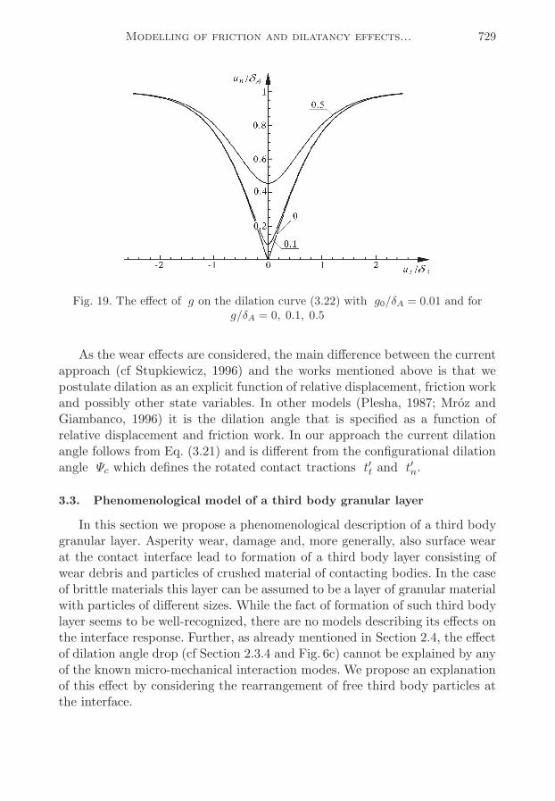
Two examples of cyclic response with wear effects are shown in Fig. 20.The response in Fig. 20a is obtained with 1/κg = 0 so that the wear effectsare only due to decreasing asperity height.
Friction and dilation models based on the interaction of interlocked aspe-rities have been studied by several authors and start from the works of Patton(1966) and Jaeger (1971) who considered wedge-like asperities and a constantdilation angle. Models with dilation angle decreasing with increasing shear di-splacement have been proposed by Plesha (1987), Snyman and Martin (1992)and Mróz and Giambanco (1996). Additional effects, such as the effect of wearon asperity slope (and dilation angle), as well as independent evolution of ”ri-ght” and ”left” asperity slopes, have also been accounted for by Plesha (1987).Mróz and Giambanco (1996) additionally considered the micro-slip phenome-na, and Giambanco and Di Gati (1997) extended the asperity interaction modeby adding cohesion and softening effects.
Modelling of friction and dilatancy effects... 729
Fig. 19. The effect of g on the dilation curve (3.22) with g0/δA = 0.01 and forg/δA = 0, 0.1, 0.5
As the wear effects are considered, the main difference between the currentapproach (cf Stupkiewicz, 1996) and the works mentioned above is that wepostulate dilation as an explicit function of relative displacement, friction workand possibly other state variables. In other models (Plesha, 1987; Mróz andGiambanco, 1996) it is the dilation angle that is specified as a function ofrelative displacement and friction work. In our approach the current dilationangle follows from Eq. (3.21) and is different from the configurational dilationangle Ψc which defines the rotated contact tractions t
′t and t
′n.
3.3. Phenomenological model of a third body granular layer
In this section we propose a phenomenological description of a third bodygranular layer. Asperity wear, damage and, more generally, also surface wearat the contact interface lead to formation of a third body layer consisting ofwear debris and particles of crushed material of contacting bodies. In the caseof brittle materials this layer can be assumed to be a layer of granular materialwith particles of different sizes. While the fact of formation of such third bodylayer seems to be well-recognized, there are no models describing its effects onthe interface response. Further, as already mentioned in Section 2.4, the effectof dilation angle drop (cf Section 2.3.4 and Fig. 6c) cannot be explained by anyof the known micro-mechanical interaction modes. We propose an explanationof this effect by considering the rearrangement of free third body particles atthe interface.
730 S. Stupkiewicz, Z.Mróz
Fig. 20. Configurational dilation with wear effects: friction and dilation response for(a) 1/κg = 0 and (b) 1/κg > 0
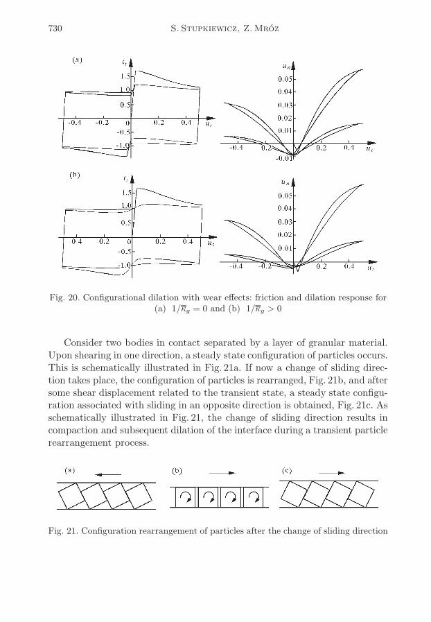
Consider two bodies in contact separated by a layer of granular material.Upon shearing in one direction, a steady state configuration of particles occurs.This is schematically illustrated in Fig. 21a. If now a change of sliding direc-tion takes place, the configuration of particles is rearranged, Fig. 21b, and aftersome shear displacement related to the transient state, a steady state configu-ration associated with sliding in an opposite direction is obtained, Fig. 21c. Asschematically illustrated in Fig. 21, the change of sliding direction results incompaction and subsequent dilation of the interface during a transient particlerearrangement process.
Fig. 21. Configuration rearrangement of particles after the change of sliding direction
Modelling of friction and dilatancy effects... 731
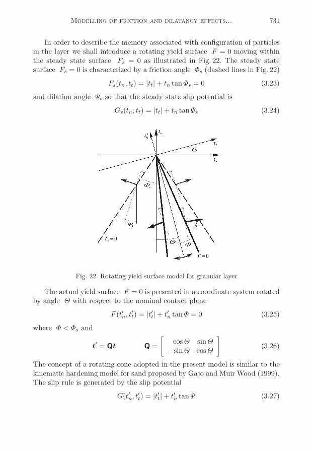
In order to describe the memory associated with configuration of particlesin the layer we shall introduce a rotating yield surface F = 0 moving withinthe steady state surface Fs = 0 as illustrated in Fig. 22. The steady statesurface Fs = 0 is characterized by a friction angle Φs (dashed lines in Fig. 22)
Fs(tn, tt) = |tt|+ tn tanΦs = 0 (3.23)
and dilation angle Ψs so that the steady state slip potential is
Gs(tn, tt) = |tt|+ tn tanΨs (3.24)
Fig. 22. Rotating yield surface model for granular layer
The actual yield surface F = 0 is presented in a coordinate system rotatedby angle Θ with respect to the nominal contact plane
F (t′n, t′
t) = |t′
t|+ t′
n tanΦ = 0 (3.25)
where Φ < Φs and
t′ = Qt Q =
[cosΘ sinΘ− sinΘ cosΘ
](3.26)
The concept of a rotating cone adopted in the present model is similar to thekinematic hardening model for sand proposed by Gajo and Muir Wood (1999).The slip rule is generated by the slip potential
G(t′n, t′
t) = |t′
t|+ t′
n tanΨ (3.27)
732 S. Stupkiewicz, Z.Mróz
so that
u′s = λ′
∂G′
∂t′= λ′m′ m
′ =
[s′
tanΨ
]s′ =
t′t|t′t|
(3.28)
where u′s = Qus is the (inelastic) relative velocity in the rotated coordinatesystem. Note that the effective dilation angle (i.e. the dilation angle in theglobal coordinate system) is
Ψeff = arctanusn|ust |= s′Θ + Ψ (3.29)
where Ψeff > 0 for usn > 0 (dilation) and Ψeff < 0 for u
sn < 0 (compaction).
In the steady state the stress point lies on the steady state surface Fs = 0so that the rotation angle Θ equals Θs = s
′(Φs − Φ). Thus we assume asimple law to describe the evolution of Θ in the transient state
Θ = [s′(Φs − Φ)−Θ]κΘκΘ
(3.30)
where the hardening variable κΘ is defined by (other forms including frictionalwork are also possible)
κΘ = |ust | (3.31)
and κΘ is a model parameter (i.e. a characteristic sliding displacement relatedto the rotation of the yield surface F = 0).
We also assume that in the steady state the effective dilation angle Ψeffis equal to the steady state dilation angle Ψs. This condition provides thefollowing relation between the dilation angles Ψ and Ψs
Ψ = Ψs − s′Θs = Ψs − (Φs − Φ) (3.32)
which, importantly, is assumed to hold also in the transient states.
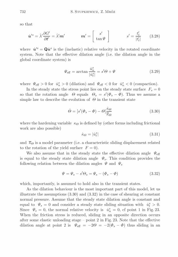
As the dilation behaviour is the most important part of this model, let usillustrate the assumptions (3.30) and (3.32) in the case of shearing at constantnormal pressure. Assume that the steady state dilation angle is constant andequal to Ψs = 0 and consider a steady state sliding situation with u
st > 0.
Since Ψs = 0, the normal relative velocity is usn = 0, cf point 1 in Fig. 23.
When the friction stress is reduced, sliding in an opposite direction occursafter some elastic unloading stage – point 2 in Fig. 23. Note that the effectivedilation angle at point 2 is Ψeff = −2Θ = −2(Φs − Φ) thus sliding in an
Modelling of friction and dilatancy effects... 733
opposite direction is associated with non-zero compaction velocity, Fig. 23b.We can integrate (3.30) along the path 2-3-4 analytically, so that
Θ = (Φs − Φ)(2eust−ust
κΘ − 1)
(3.33)
where ust ¬ 0 is the sliding displacement at load reversal.
Fig. 23. Rotating cone model (with Ψs = 0): (a) evolution of the yield surface uponload reversal; (b) dilatancy and frictional response
Assuming that the effective dilation angle Ψeff is small, for s′ = −1 we
can write
dusn = Ψeff |dust | = (s
′Θ + Ψ)s′ dust = (Θ − Ψ)dust =
(3.34)
= 2(Φs − Φ)eust−ust
κΘ dust
where we have also used (3.32) and (3.33). Integrating (3.34) along the path2-3-4 we finally obtain the dilation response, namely
usn − usn
κΘ= 2(Φs − Φ)
(eust−ust
κΘ − 1)
(3.35)
where usn is the relative normal displacement at load reversal. The dilatancyand frictional response resulting from the solution (3.33) and (3.35) is depictedin Fig. 23b.
734 S. Stupkiewicz, Z.Mróz
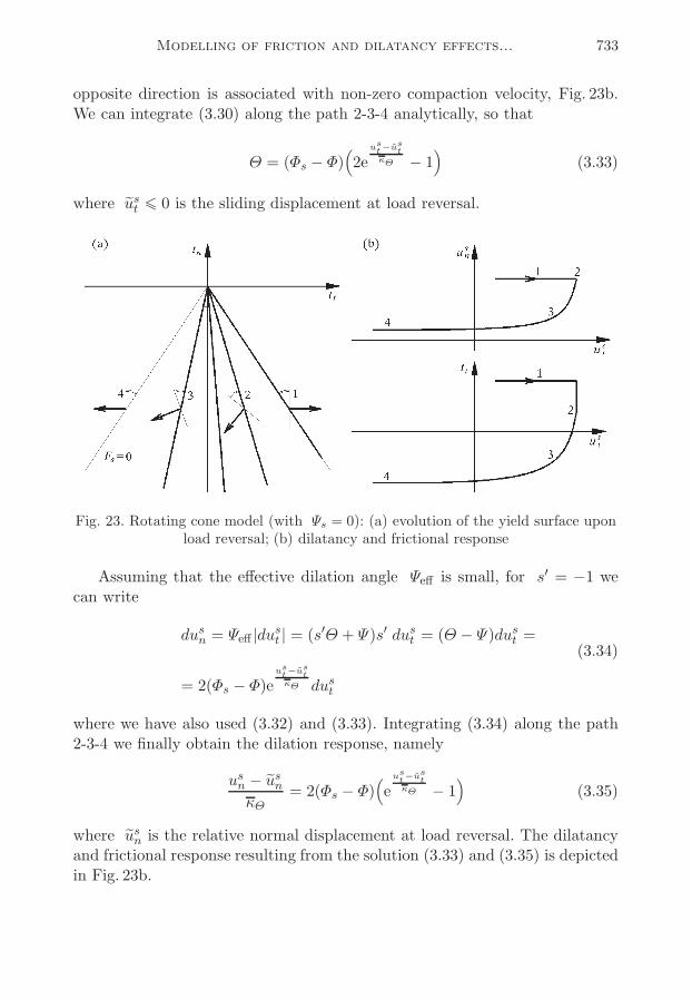
Let us note that the assumptions adopted in the above example resultin contact compaction at each load reversal (∆usn = −2(Φs − Φ)κΘ betweensteady sliding states, cf Eq. (3.35)). Since this is a non-physical result, we shallno longer assume that the steady state dilation angle Ψs is constant. Insteadwe assume that there is an asymptotic thickness of the granular layer whichdepends on the normal pressure. Thus even for the points of the steady statesurface some dilation may occur until the asymptotic thickness is attained.We thus propose the following evolution law for Ψs
Ψs = −[usn − uasnκΨ
+ 2ηΨs] κΨκΨ
κΨ = |ust | (3.36)
where uasn = uasn (tn) is a relative normal displacement related to the asymp-
totic thickness of the layer and κΨ is a parameter providing the displacementscale for evolution of Ψs. Since in view of (3.30) and (3.32), equation (3.36) isin fact a second order differential equation for usn(u
st ), we introduce a critical
damping term 2ηΨs with η > 1 in order to avoid oscillatory solutions. Thedilatancy response to cyclic shearing is schematically shown in Fig. 24.
Fig. 24. Rotating cone model for granular layer: dilatancy response to cyclic shearing
Concluding, the model of the third body granular layer involves the yieldsurface (3.25) and the slip rule (3.28) accompanied by the evolution laws forrotation angle Θ and steady state dilation angle Ψc, Eqs (3.30) and (3.36).The parameters of the model are: Φs, Φ, κΘ and κΨ . Also the function u
asn (tn)
must be specified (as the first approximation we may assume uasn = 0).
4. Discussion and conclusions
The friction and dilatancy effects at brittle interfaces have been studied inthe paper. As already discussed, the term brittle interfaces denotes a wide class
Modelling of friction and dilatancy effects... 735
of both cohesive and non-cohesive interfaces where the contacting bodies arebrittle. This, however, implies another common characteristic feature, namelythe wear debris and the material of crushed asperities form a third body layerwhich can be regarded a granular material. Also, even more importantly, inpractice most of the brittle interfaces are characterized by interlocked aspe-rities and related friction and dilatancy effects. The latter effects are crucialfor constitutive modelling, especially in the case of non-monotonic and cyclicloading programs.
We have shown that some of the effects observed in the experiments mayresult from more than one mechanism. This mostly regards the monotonicresponse effects, such as peak friction and dilation in direct shear (effectsA.3 and A.6 in Table 2). Thus the response to monotonic shearing may notbe sufficient to distinguish between the mechanisms and, quite obviously, topredict the non-monotonic or cyclic response.
The most important micro-mechanisms occurring at brittle interfaces havebeen identified, namely decohesion, interaction of interlocked primary asperi-ties including wear and damage and formation of a third body granular layer.Simple constitutive models have also been proposed providing description ofeach of these mechanisms separately, and through a qualitative analysis thepredicting capabilities of the models have been assessed.
The analysis of existing models for cohesive interfaces (Section 3.1) leadsto the conclusion that these models are mostly suitable for monotonic loadingprocesses. Particularly, the predictions of cyclic dilation response, cf Fig. 12b,are qualitatively different from the typical response types observed in experi-ments, cf Fig. 6. The reason is that most of these models neglect the interlockedasperity interaction mode. The model of Giambanco and Di Gati (1997) is anexception as it provides a transition from the cohesive mode to the asperityinteraction mode.
In Section 3.2, a model of configurational dilatancy has been proposed. Thismodel generalizes the concepts of interaction of interlocked primary asperities(well-known in the field of rock joints). The model provides a transition fromthe interlocked to the random asperity contact mode with increasing shearingdisplacement and describes the related friction and dilatancy effects. A refinedmodel might also include the description of the evolution of elastic stiffnessproperties of the interface coupled with the transition from the interlocked tothe random asperity contact, cf Fig. 3.
Finally, in Section 3.3, a model for a granular third body layer has beenproposed based on the concept of a rotating cone representing rearrangementof particle configurations associated with shearing in different directions. The
736 S. Stupkiewicz, Z.Mróz
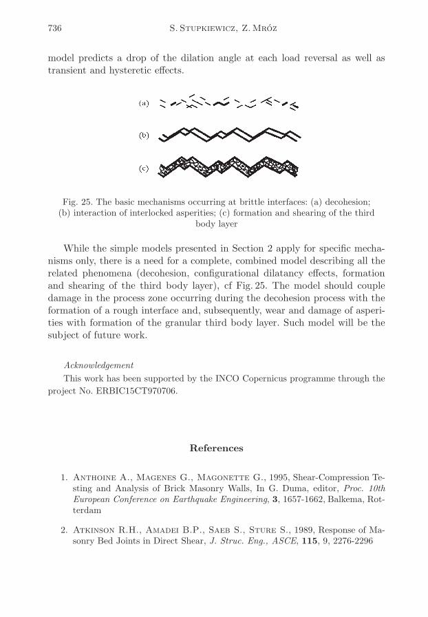
model predicts a drop of the dilation angle at each load reversal as well astransient and hysteretic effects.
Fig. 25. The basic mechanisms occurring at brittle interfaces: (a) decohesion;(b) interaction of interlocked asperities; (c) formation and shearing of the third
body layer
While the simple models presented in Section 2 apply for specific mecha-nisms only, there is a need for a complete, combined model describing all therelated phenomena (decohesion, configurational dilatancy effects, formationand shearing of the third body layer), cf Fig. 25. The model should coupledamage in the process zone occurring during the decohesion process with theformation of a rough interface and, subsequently, wear and damage of asperi-ties with formation of the granular third body layer. Such model will be thesubject of future work.
Acknowledgement
This work has been supported by the INCO Copernicus programme through the
project No. ERBIC15CT970706.
References
1. Anthoine A., Magenes G., Magonette G., 1995, Shear-Compression Te-sting and Analysis of Brick Masonry Walls, In G. Duma, editor, Proc. 10thEuropean Conference on Earthquake Engineering, 3, 1657-1662, Balkema, Rot-terdam
2. Atkinson R.H., Amadei B.P., Saeb S., Sture S., 1989, Response of Ma-sonry Bed Joints in Direct Shear, J. Struc. Eng., ASCE, 115, 9, 2276-2296
Modelling of friction and dilatancy effects... 737
3. Bandis S., Lumsden A.C., Barton N.R., 1981, Experimental Studies ofScale Effect on the Shear Behaviour of Rock Joints, Int. J. Rock Mech. Min.Sci. Geomech. Abstr., 18, 1-21
4. Bandis S.C., Lumsden A.C., Barton N.R., 1983, Fundamentals of RockJoint Deformation, Int. J. Rock Mech. Min. Sci. Geomech. Abstr., 20, 249-268
5. Binda L., Mirabella G., Tiraboschi C., Abbaneo S., 1994, MeasuringMasonry Material Properties, In: Proc. U.S.-Italy Workshop on Guidelines forSeismic Evaluation and Rehabilitation of Unreinforced Masonry Buildings, pp.6-3/24, State Univ. of New York at Buffalo, NCEER-94-0021
6. Carter W.C., Butler E.P., Fuller E.R., Jr., 1991, Micro-MechanicalAspects of Asperity-Controlled Friction in Fiber Toughened Ceramic Compo-sites, Scripta Metall. Mater., 25, 579-584
7. Cherouali H., Reynaud P., Berthier Y., Rouby D., 1997, Influence ofSerrated Sliding on Subsequent Steady Slip in Single Filament Model Compo-site SiC/Pyrex, Scripta Metall., 36, 11, 1283-1288
8. Fox D.J., Kana D.D., Hsiung S.M., 1998, Influence of Interface Roughnesson Dynamic Shear Behavior in Jointed Rock, Int. J. Rock Mech. Min. Sci., 35,7, 923-940
9. Gajo A., Muir Wood D., 1999, A Kinematic Hardening Constitutive Modelfor Sands: The Multiaxial Formulation, Int. J. Num. Anal. Meth. Geomech.,23, 925-965
10. Gambarotta L., Lagomarsino S., 1997, Damage Models for the SeismicResponse of Brick Masonry Shear Walls, Part I: The Mortar Joint Model andits Applications, Earthquake Engrg. Struct. Dyn., 26, 441-462
11. Gens A., Carol I., Alonso E.E., 1989, Elasto-Plastic Model for Joints andInterfaces, In: D.R.J. Owen et al., editor, Proc. 2nd Int. Conf. ComputationalPlasticity, 1251-1264, Swansea, UK, Pineridge Press
12. Gerrard C., 1986, Shear Failure of Rock Joints: Appropriate Constraintsfor Empirical Relations, Int. J. Rock Mech. Min. Sci. Geomech. Abstr., 23, 6,421-429
13. Giambanco G., Di Gati L., 1997, A Cohesive Interface Model for the Struc-tural Mechanics of Block Masonry, Mech. Res. Commun., 24, 5, 503-512
14. Hutson R.W., Dowding C.H., 1990, Joint Asperity Degradation DuringCyclic Shearing, Int. J. Rock Mech. Min. Sci. Geomech. Abstr., 27, 2, 109-119
15. Jaeger J.C., 1971, Friction of Rocks and Stability of Rock Slopes, Geotech-nique, 21, 2, 97-134
16. Jero P.D., Kerans R.J., Parthasarathy T.A., 1991, Effect of InterfacialRoughness on the Frictional Stress Measured Using Pushout Tests, J. Am.Ceram. Soc., 74, 11, 2793-2801
738 S. Stupkiewicz, Z.Mróz
17. Jing L., 1990, Numerical Modelling of Jointed Rock Masses by Distinct Ele-ment Method for Two- and Three-Dimensional Problems, PhD Thesis, LuleaUniversity of Technology
18. Kutter H.K., Weissbach G., 1980, Der Einfluss von Verformungs- und Bela-stungsgeschichte auf den Scherwiderstand von Gesteinskluften unter BesondererBerucksichtigung der Mylonitbildung. Final Report, DFG Research Project Ku361/2/4
19. Lotfi H.R., Shing P.B., 1994, Interface Model Applied to Fracture of Ma-sonry Structures, J. Struct. Engrg., ASCE, 120, 1, 63-80
20. Lourenco P.B., Rots J.G., 1997, Multisurface Interface Model for Analysisof Masonry Structures, J. Eng. Mech. ASCE, 123, 7, 660-668
21. Marshall D.B., Oliver W.C, 1990, An Indentation Method for MeasuringResidual Stresses in Fiber-Reinforced Ceramics, Mat. Sci. Engrg. A, 126, 95-103
22. Marshall D.B., Shaw M.C., Morris W.L., 1992, Measurement of Interfa-cial Debonding and Sliding Resistance in Fiber Reinforced Intermetallics, ActaMetall. Mater., 40, 3, 443-454
23. Mróz Z., Giambanco G., 1996, An Interface Model for Analysis of Defor-mation Behaviour of Discontinuities, Int. J. Num. Anal. Meth. Geomech., 20,1-33
24. Mróz Z., Stupkiewicz S., 1994, An Anisotropic Friction and Wear Model,Int. J. Sol. Struct., 31, 8, 1113-1131
25. Mróz Z., Stupkiewicz S., 1998, Constitutive Model of Adhesive and Plo-ughing Friction in Metal Forming Processes, Int. J. Mech. Sci., 40, 281-303
26. Patton F.D., 1966, Multiple Modes of Shear Failure in Rock and RelatedMaterials, PhD thesis, University of Illinois
27. Plesha M.E., 1987, Constitutive Models for Rock Discontinuities with Di-latancy and Surface Degradation, Int. J. Num. Anal. Meth. Geomech., 11,345-362
28. van der Pluijm R., 1993, Shear Behaviour of Bed Joints, In: A.A. Hamidand H.G. Harris, editors, Proc. 6th North American Masonry Conf., 125-136,Drexel University, Philadelphia, Pennsylvania, USA
29. van der Pluijm R., 1997, Non-Linear Behavior of Masonry Under Tension,Heron, 42, 1, 25-54
30. Raous M., Cangemi L., Cocu M., 1999, A Consistent Model Coupling Ad-hesion, Friction and unilateral Contact, Comp. Meth. Appl. Mech. Engrg., 177,383-399
31. Snyman M.F., Martin J.B., 1992, A Consistent Formulation of a DilatantInterface Element, Int. J. Num. Anal. Meth. Geomech., 16, 493-527
Modelling of friction and dilatancy effects... 739
32. Stupkiewicz S., 1996, Fiber Sliding Model Accounting for Interfacial Micro-Dilatancy, Mech. Mater., 22, 65-84
33. Sun Z., Gerrard C., Stephanson O., 1985, Rock Joint Compliance Tests forCompression and Shear Loads, Int. J. Rock Mech. Min. Sci. Geomech. Abstr.,4, 197-213
Modelowanie tarcia i dylatacji w kruchych warstwach kontaktowych przy
obciążeniach monotonicznych i cyklicznych
Streszczenie
Praca zawiera analizę najważniejszych efektów powstających w procesach defor-macji kruchych warstw kontaktowych przy obciążeniach monotonicznych i cyklicz-nych. Dostępne modele konstytutywne poddano krytycznej analizie pod kątem możli-wości opisania tych efektów. Rozważono liczne mechanizmy mikromechaniczne, takiejak dekohezja, oddziaływanie pierwotnych i wtórnych nierówności, zużycie i uszkodze-nie nierówności oraz powstawanie warstwy trzeciego ciała. Zaproponowano równieżnowe sformułowania modeli konstytutywnych dla stanów cyklicznych.
Manuscript received December 20, 2000; accepted for print January 8, 2001