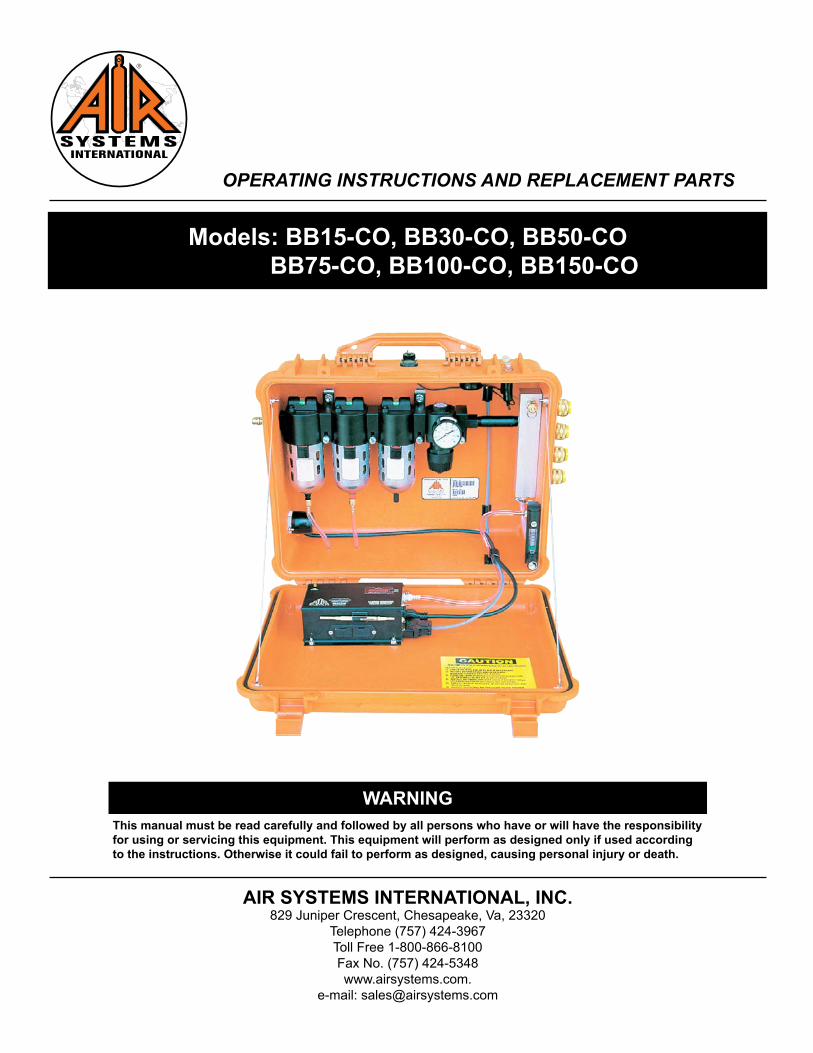
OPERATING INSTRUCTIONS AND REPLACEMENT PARTS Models: BB15-CO, BB30-CO, BB50-CO BB75-CO, BB100-CO, BB150-CO AIR SYSTEMS INTERNATIONAL, INC. 829 Juniper Crescent, Chesapeake, Va, 23320 Telephone (757) 424-3967 Toll Free 1-800-866-8100 Fax No. (757) 424-5348 www.airsystems.com. e-mail: [email protected]This manual must be read carefully and followed by all persons who have or will have the responsibility for using or servicing this equipment. This equipment will perform as designed only if used according to the instructions. Otherwise it could fail to perform as designed, causing personal injury or death. WARNING
this manual must be read carefully and followed by all persons who have or will have the responsibility for using or servicing this equipment. this equipment will perform as designed only if used according to the instructions. Otherwise it could fail to perform as designed, causing personal injury or death.
WArninG
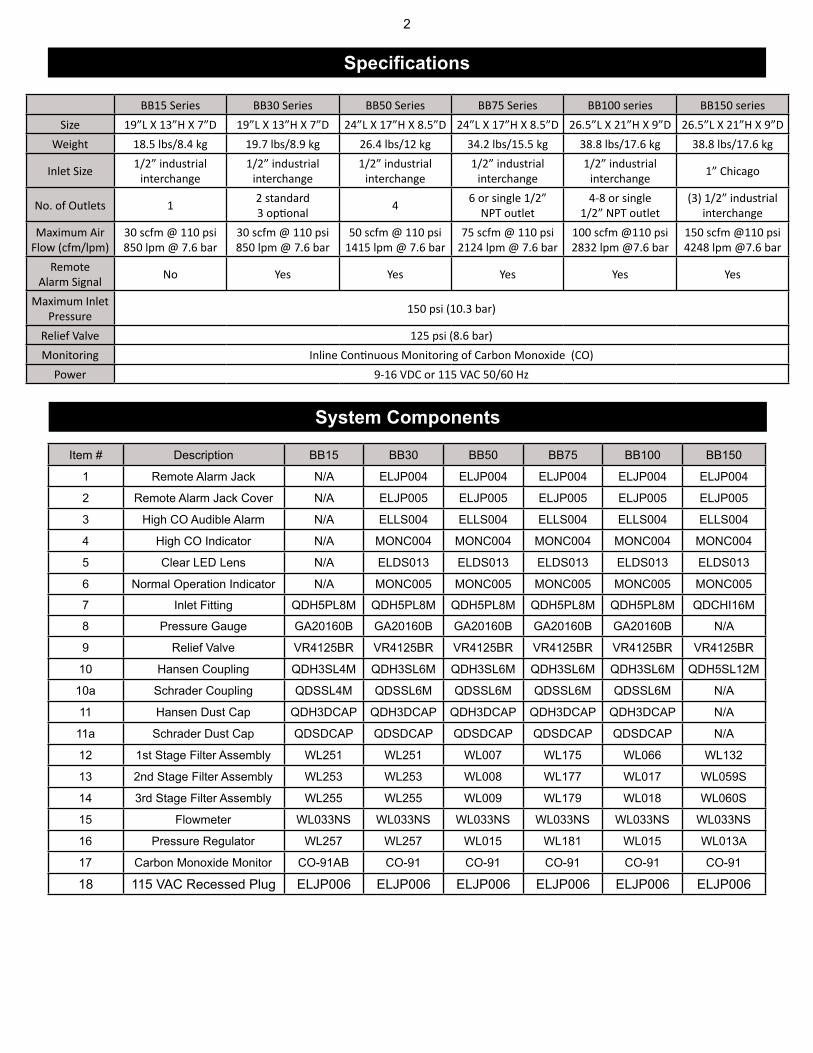
BB15 Series BB30 Series BB50 Series BB75 Series BB100 series BB150 seriesSize 19”L X 13”H X 7”D 19”L X 13”H X 7”D 24”L X 17”H X 8.5”D 24”L X 17”H X 8.5”D 26.5”L X 21”H X 9”D 26.5”L X 21”H X 9”D
Weight 18.5 lbs/8.4 kg 19.7 lbs/8.9 kg 26.4 lbs/12 kg 34.2 lbs/15.5 kg 38.8 lbs/17.6 kg 38.8 lbs/17.6 kg
Inlet Size 1/2” industrial interchange
1/2” industrial interchange
1/2” industrial interchange
1/2” industrial interchange
1/2” industrial interchange 1” Chicago
No. of Outlets 1 2 standard3 opti onal 4 6 or single 1/2”
The responsibility for the quality of breathing air rests with the user. Compliance with federal, state, or local regulations are the responsibility of the user and this recommendation does not supersede any existing rules, regulations, or laws which may apply. Breathing air fi ltration products meet or exceed CGA Grade-D specifi cations for air quality as adopted by Federal OSHA. Compressor air quality standards meet or exceed OSHA 1910.134 requirements. When the components are used in accordance with the manufacturer's instructions and recommendations, the "system" meets or exceeds federal regulations presently in force. It is incumbent upon the user to comply with any changes in the regula-tions or law which may occur in future situations. The air supply compressor should be located in a safe, clean ambient air environment. This "safe" location should be tested periodically using proper instruments to ensure clean ambient air quality on a consistent basis. Total system Grade-D air quality should be tested at the time of initial setup. If the compressor is moved, retesting air quality is recom-mended. Should the location or environment signifi cantly change, the air quality should be retested. The compressor fi lters and oil level should be checked daily and changed when contaminated or when the maximum number of "run" hours is achieved. This series of air fi ltration units should be used according to the recommendations specifi ed in the manual. The standard fi ltration package is not explosion-proof and should be located in a non-explosive environment. (An intrinsically safe model is available, please contact the factory for information.) The carbon monoxide monitor should be calibrated monthly or if the accuracy of the monitor is in question. System air quality should be tested for, but not limited to, the fol-lowing Grade-D air components:
CO - Carbon MonoxideO2 - Oxygen
CO2 - Carbon DioxideH2O - Water (Moisture Content)
Hydrocarbons (Oil Mist)Total Particulates
The maximum allowable level of these air quality components varies depending on Grade-D or E requirements. Contact sales for a copy of the latest standards.
Our Breathing Air compressors and fi ltration systems meet all of the following federal specifi cations when used and serviced in accordance with our instructions.
Federal OSHA 29 CFR 1910.134"Compressor Operations for Breathing Air"
Army Corps of Engineers EM385-1-1,
paragraph 07b-11-4"Compressed Breathing Air"
4
Breathing Air Quality Position Statement
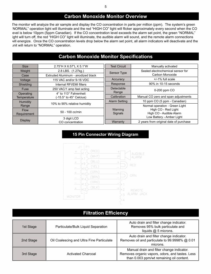
The monitor will analyze the air sample and display the CO concentration in parts per million (ppm). The system’s green “NORMAL” operation light will illuminate and the red “HIGH CO” light will fl icker approximately every second when the CO level is below 10ppm (5ppm Canadian). If the CO concentration level exceeds the alarm set point, the green “NORMAL” light will turn off, the red “HIGH CO” light will illuminate, the audible alarm will sound, and the remote alarm connections will energize. Once the CO concentration levels drop below the alarm set point, all alarm indicators will deactivate and the unit will return to “NORMAL” operation.
15 Pin Connector Wiring Diagram
5
Carbon Monoxide Monitor Overview
Size 2.75”H X 6.57”L X 5.1”WWeight 2.8 LBS. (1.27kg.)Case Extruded Aluminum - anodized black
Voltage 115 VAC and/or 9-16 VDCShielding Internal RFI/EMI fi lters
Fuse 250 VAC/1 amp fast actingOperating
Temperature4° to 113° Fahrenheit(-15.5° to 45° Celcius)
HumidityRange 10% to 90% relative humidity
FlowRequirement 50 - 100 cc/min
Display 3 digit LCDCO concentration
Test Circuit Manually activated
Sensor Type Sealed electrochemical sensor forCarbon Monoxide
Accuracy +/-1% full scaleResponse 90% in 10-15 secondsDetectable
Range 0-200 ppm CO
Calibration Manual CO zero and span adjustmentsAlarm Setting 10 ppm CO (5 ppm - Canadian)
WarningSignals
Normal operation - Green LightHigh CO - Red Light
High CO - Audible AlarmLow Battery - Amber Light
Warranty 2 years from original date of purchase
Carbon Monoxide Monitor Specifications
1st Stage Particulate/Bulk Liquid SeparationAuto drain and fi lter change indicator. Removes 95% bulk particulate and
liquids @ 5 microns.
2nd Stage Oil Coalescing and Ultra Fine ParticulateAuto drain and fi lter change indicator.
Removes oil and particulate to 99.9998% @ 0.01 microns.
3rd Stage Activated CharcoalManual drain and fi lter change indicator.
Removes organic vapors, odors, and tastes. Less than 0.003 ppm/wt remaining oil content.
Filtration Efficiency
6
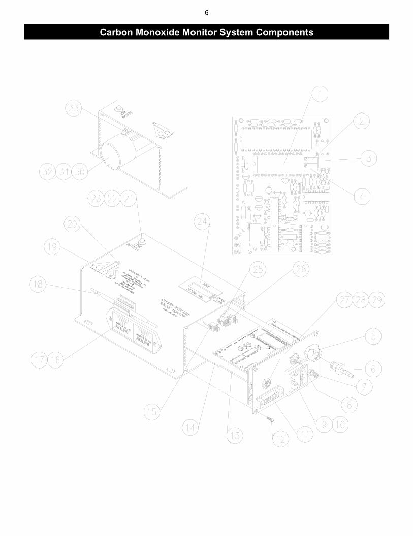
Carbon Monoxide Monitor System Components
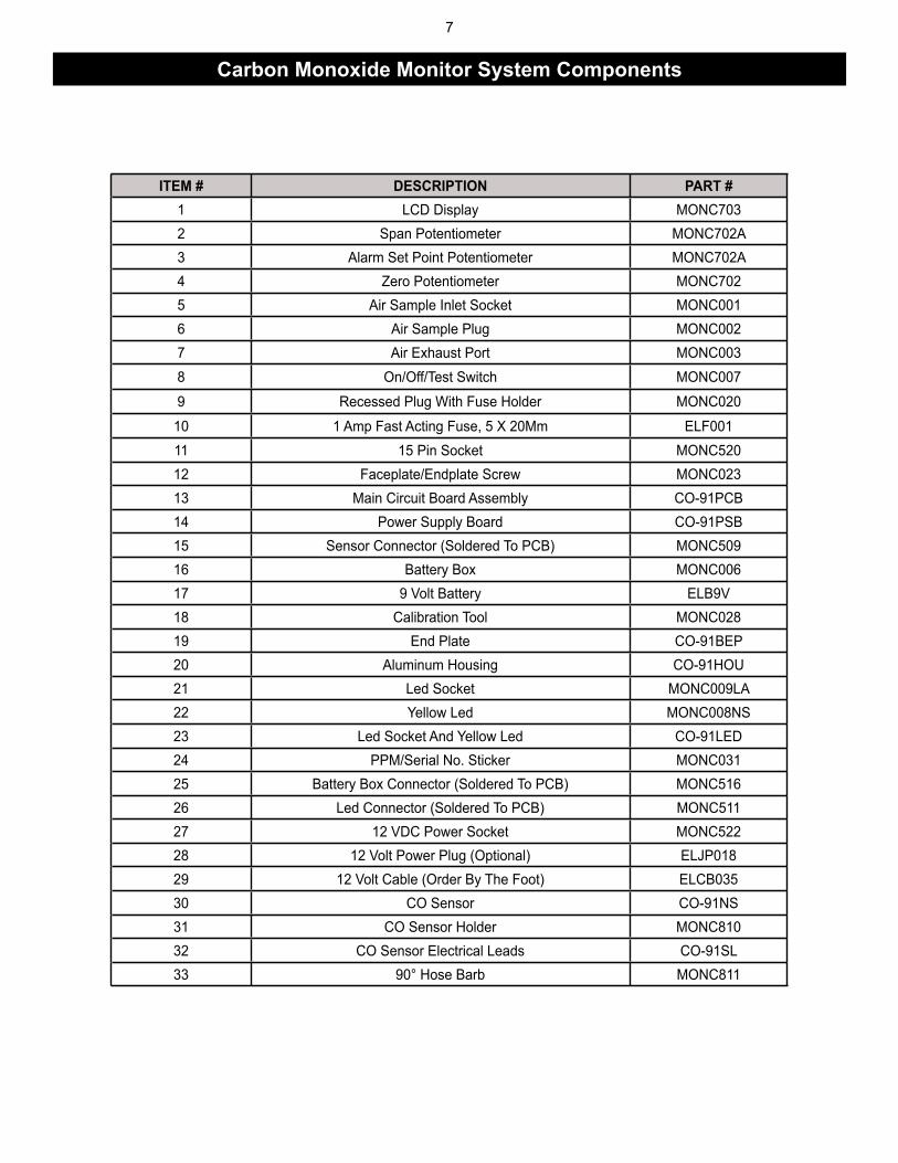
iteM # DeSCriPtiOn PArt #1 LCD Display MONC7032 Span Potentiometer MONC702A3 Alarm Set Point Potentiometer MONC702A4 Zero Potentiometer MONC7025 Air Sample Inlet Socket MONC0016 Air Sample Plug MONC0027 Air Exhaust Port MONC0038 On/Off/Test Switch MONC007
9 Recessed Plug With Fuse Holder MONC020
10 1 Amp Fast Acting Fuse, 5 X 20Mm ELF00111 15 Pin Socket MONC52012 Faceplate/Endplate Screw MONC02313 Main Circuit Board Assembly CO-91PCB14 Power Supply Board CO-91PSB15 Sensor Connector (Soldered To PCB) MONC50916 Battery Box MONC00617 9 Volt Battery ELB9V18 Calibration Tool MONC02819 End Plate CO-91BEP20 Aluminum Housing CO-91HOU21 Led Socket MONC009LA22 Yellow Led MONC008NS23 Led Socket And Yellow Led CO-91LED24 PPM/Serial No. Sticker MONC03125 Battery Box Connector (Soldered To PCB) MONC51626 Led Connector (Soldered To PCB) MONC51127 12 VDC Power Socket MONC52228 12 Volt Power Plug (Optional) ELJP01829 12 Volt Cable (Order By The Foot) ELCB03530 CO Sensor CO-91NS31 CO Sensor Holder MONC81032 CO Sensor Electrical Leads CO-91SL33 90° Hose Barb MONC811
7
Carbon Monoxide Monitor System Components
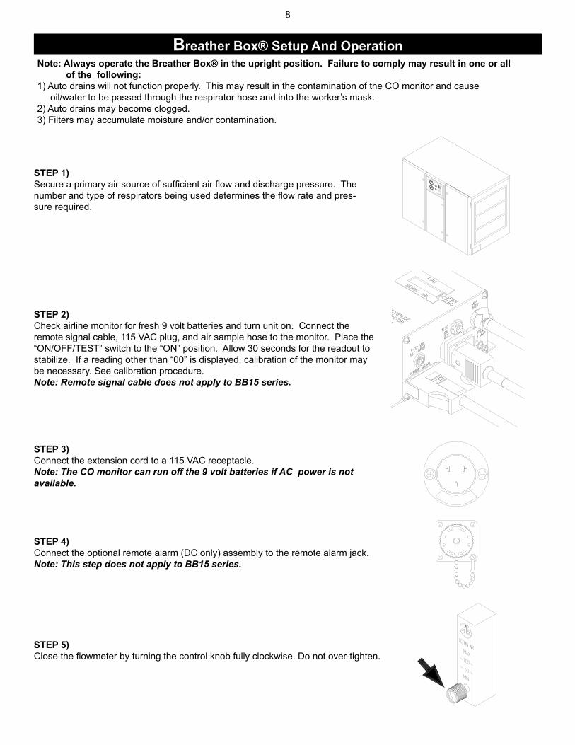
SteP 1)Secure a primary air source of sufficient air flow and discharge pressure. The number and type of respirators being used determines the flow rate and pres-sure required.
SteP 2)Check airline monitor for fresh 9 volt batteries and turn unit on. Connect the remote signal cable, 115 VAC plug, and air sample hose to the monitor. Place the “ON/OFF/TEST” switch to the “ON” position. Allow 30 seconds for the readout to stabilize. If a reading other than “00” is displayed, calibration of the monitor may be necessary. See calibration procedure.Note: Remote signal cable does not apply to BB15 series.
SteP 3)Connect the extension cord to a 115 VAC receptacle. Note: The CO monitor can run off the 9 volt batteries if AC power is not available.
SteP 4)Connect the optional remote alarm (DC only) assembly to the remote alarm jack. Note: This step does not apply to BB15 series.
SteP 5)Close the flowmeter by turning the control knob fully clockwise. Do not over-tighten.
note: Always operate the Breather Box® in the upright position. Failure to comply may result in one or all of the following:1) Auto drains will not function properly. This may result in the contamination of the CO monitor and cause oil/water to be passed through the respirator hose and into the worker’s mask.2) Auto drains may become clogged.3) Filters may accumulate moisture and/or contamination.
8
Breather Box® Setup And Operation
MODEL # MIN. HOSE I.D. INLET FITINGBB15 Series 3/8” 1/2” Industrial Interchange
BB30-100 Series 1/2” 1/2” Industrial InterchangeBB150 Series 3/4” 1” Chicago Fitting
SteP 6)Connect the air source, 150 psi max., to the inlet fitting.
SteP 7)Hold the “ON/OFF/TEST” switch in the “TEST” position. All local and remote audible/vi-sual indicators will activate. If indicators do not activate, check all electrical connections, then call factory repair dept. Note: An alarm function test can be performed at any time by lifting the “ON/OFF/TEST” switch to the “TEST” position.
SteP 8)Attach desired respirators and hoses to the quick connect couplings.Note: Some models may not have respirator connections. They may be ordered with NPT outlets for connection to points-of-attachment.
SteP 9)Adjust the outlet pressure to the setting recommended by the respirator manufacturer. Turn the knob clockwise to increase pressure, counterclockwise to decrease pressure.
SteP 10) Adjust CO monitor air sample flow rate by turning the flowmeter control knob counterclockwise until the ball hovers between 50 and 100 cc/min. The box is now ready for operation.The monitor will analyze the air sample and display the CO concentration in parts per million (ppm). The system’s green “NORMAL” operation light will illuminate, and the red “HIGH CO” light will flicker faintly approximately every second when the CO level is below 10ppm (5ppm Canadian).When the CO concentration level exceeds the alarm set point, the green “NORMAL” light will turn off, the red “HIGH CO” light illuminates, the audible alarm will sound, and the remote alarm connections will energize.When CO concentrations drop below the alarm set point, all alarm indicators will deactivate and return to normal operation.
9
Breather Box® Setup And Operation
10
Filter Housing/Bowls: Periodic cleaning of the polycarbonate bowls may become necessary. Remove the auto drains and clean the bowls with a mild soapy solution. The auto drains may also be cleaned with a mild soapy solution at this time.Dry and reinstall into the fi lter housing. Filter Change: The fi ltration system consists of fi lter change indicators which will gradually change from green to orange when fi lter life is spent. note: Air must be fl owing through the fi lters before the fi lter change indicators will function.
Calibration: Monitor calibration should be done monthly or whenever the reading may be questionable. A calibration date sticker should be affi xed for future reference. To obtain an accurate calibration, we recommend the use of Air Systems’calibration kits. Part number:BBK-10 Canadian calibration kit for CO monitor; 10ppm CO, zero air, regulator and case - 17 liter size.
BBK-20 Calibration kit for CO monitor; 20ppm CO, zero air, regulator and case - 17 liter size.
BBK-20103 Calibration kit for CO monitor; 20ppm CO, zero air, regulator and case - 103 liter size.
To assure sensor accuracy, calibration of monitor is required. If you cannot obtain an accurate calibration, sensor replace-ment may be necessary. Consult Repair Service Department before ordering. Part number: CO-91NS Replacement CO sensor
CAUtiOn: Always depressurize the system before performing service.
1) Make sure all personnel have egressed from the work area.2) Shut off air source to the box.3) Remove air pressure from the box by pulling the relief valve ring out.4) Turn the CO monitor OFF. Do not remove the 9 volt batteries. These are used to maintain a bias voltage to the sensor. This keeps the sensor ready for immediate use.5) Disconnect airline hoses.6) Install dust caps if applicable.
These batteries provide the required continuous bias voltage to the CO sensor and power the monitor in the event of AC power loss. If AC and DC power are removed for a period of 2 hours or more, a 1 hour restabilization period is required as eratic readings may occur.
Battery replacement: Replace 9 volt batteries when the amber “Low Battery” light illuminates. If the monitor is not used for 90 days, check the 9 volt batteries and replace if necessary.
Shutdown Procedure
System Maintenance
Monitor Battery replacement
11
Replacement sensors are shipped with a metal spring installed between the electrodes. Do not remove the clip until the sensor is to be installed into the monitor.
Step 1)Disconnect all external connections.Remove CO monitor from the unit.
Step 2)Remove the four screws from the moni-tor’s left endplate.
Step 3)Remove endplate to gain access to the sensor cup.
Step 4)Remove sensor from sensor cup and remove leads. Take the new sensor and remove the metal spring. Reattach leads to the proper colored terminals on the new sensor. Install new sensor into sensor cup.
Step 5)Reassemble monitor and reinstall in unit. Connect all cables and air sample hose. Allow monitor to stabilize 30 minutes to 1 hour and recalibrate.
SENSING(RED)
REFERENCE(BLUE)
UNUSED
CONTROL(BLACK)
Sensor replacement
12
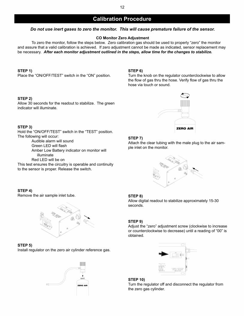
CAliBrAtiOn PrOCeDUre
Do not use inert gases to zero the monitor. This will cause premature failure of the sensor.
CO Monitor Zero Adjustment To zero the monitor, follow the steps below. Zero calibration gas should be used to properly “zero” the monitor and assure that a valid calibration is achieved. If zero adjustment cannot be made as indicated, sensor replacement may be necessary. After each monitor adjustment outlined in the steps, allow time for the changes to stabilize.
SteP 1) Place the “ON/OFF/TEST” switch in the “ON” position.
SteP 8) Allow digital readout to stabilize approximately 15-30 seconds.
SteP 10) Turn the regulator off and disconnect the regulator from the zero gas cylinder.
SteP 2)Allow 30 seconds for the readout to stabilize. The green indicator will illuminate.
SteP 3)Hold the “ON/OFF/TEST” switch in the “TEST” position. The following will occur: Audible alarm will sound Green LED will fl ash Amber Low Battery indicator on monitor will illuminate Red LED will be onThis test ensures the circuitry is operable and continuity to the sensor is proper. Release the switch.
SteP 4)Remove the air sample inlet tube.
SteP 5)Install regulator on the zero air cylinder reference gas.
SteP 7)Attach the clear tubing with the male plug to the air sam-ple inlet on the monitor.
SteP 6)Turn the knob on the regulator counterclockwise to allow the fl ow of gas thru the hose. Verify fl ow of gas thru the hose via touch or sound.
SteP 9)Adjust the “zero” adjustment screw (clockwise to increase or counterclockwise to decrease) until a reading of “00” is obtained.
Calibration Procedure
13
CAliBrAtiOn PrOCeDUreCO Monitor Span Adjustment
Use only 10-20ppm CO gas for calibration. Using a higher concentration may decrease accuracy at lower scale readings. Note: 10ppm gas must be used to satisfy Canadian calibration requirements.
SteP 1)Install regulator on the CO calibration gas cylinder.
SteP 3)Connect the plug to the air sample inlet on the monitor.
SteP 2)Turn the knob on the regulator counterclockwise to allow the fl ow of gas thru the hose. Verify fl ow of gas thru the hose via touch or sound.
SteP 4)Allow digital readout to stabilize 15-30 seconds.
SteP 5)Adjust the “span” adjustment screw (clockwise to in-crease or counterclockwise to decrease) until the digital readout reads the same as the concentration (ppm) as printed on the calibration gas cylinder.
SteP 6)Turn the regulator off and repeat the “zero” adjustment procedure. The digital readout should return to a “00” reading.
The monitor is now calibrated and should be recalibrated monthly or if accuracy is question-able. Check local requirements and recalibrate
as required.
Calibration Procedure
14
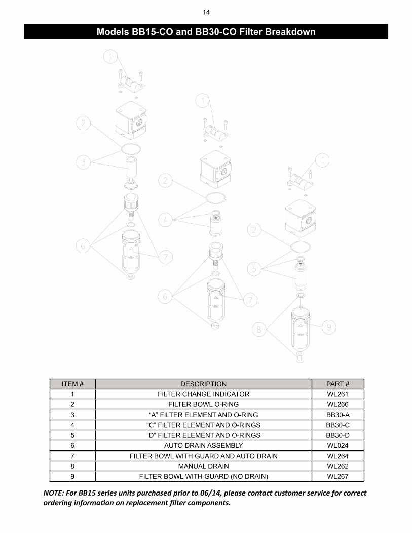
NOTE: For BB15 series units purchased prior to 06/14, please contact customer service for correct ordering information on replacement filter components.
ITEM # DESCRIPTION PART #1 FILTER CHANGE INDICATOR WL2612 FILTER BOWL O-RING WL2663 “A” FILTER ELEMENT AND O-RING BB30-A4 “C” FILTER ELEMENT AND O-RINGS BB30-C5 “D” FILTER ELEMENT AND O-RINGS BB30-D6 AUTO DRAIN ASSEMBLY WL0247 FILTER BOWL WITH GUARD AND AUTO DRAIN WL2648 MANUAL DRAIN WL2629 FILTER BOWL WITH GUARD (NO DRAIN) WL267
Models BB15-CO and BB30-CO Filter Breakdown
15
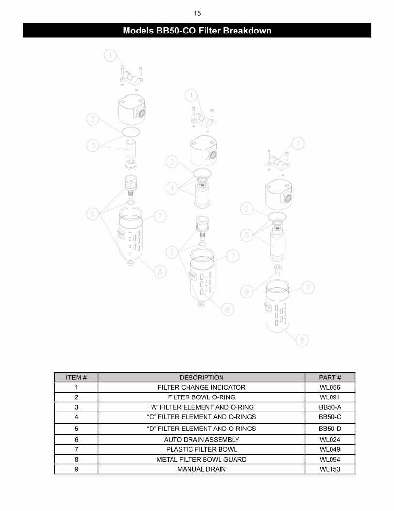
ITEM # DESCRIPTION PART #1 FILTER CHANGE INDICATOR WL0562 FILTER BOWL O-RING WL0913 “A” FILTER ELEMENT AND O-RING BB50-A4 “C” FILTER ELEMENT AND O-RINGS BB50-C
5 “D” FILTER ELEMENT AND O-RINGS BB50-D
6 AUTO DRAIN ASSEMBLY WL0247 PLASTIC FILTER BOWL WL0498 METAL FILTER BOWL GUARD WL0949 MANUAL DRAIN WL153
Models BB50-CO Filter Breakdown
16
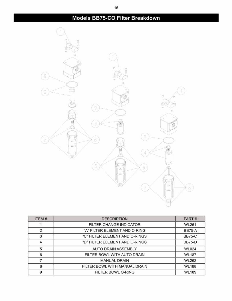
ITEM # DESCRIPTION PART #1 FILTER CHANGE INDICATOR WL2612 “A” FILTER ELEMENT AND O-RING BB75-A3 “C” FILTER ELEMENT AND O-RINGS BB75-C4 “D” FILTER ELEMENT AND O-RINGS BB75-D
5 AUTO DRAIN ASSEMBLY WL0246 FILTER BOWL WITH AUTO DRAIN WL1877 MANUAL DRAIN WL2628 FILTER BOWL WITH MANUAL DRAIN WL1889 FILTER BOWL O-RING WL189
Models BB75-CO Filter Breakdown
17
ITEM # DESCRIPTION PART #1 FILTER CHANGE INDICATOR* WL0562 FILTER BOWL O-RING WL1133 “A” FILTER ELEMENT AND O-RING BB100-A4 “C” FILTER ELEMENT AND O-RINGS BB100-C
5 “D” FILTER ELEMENT AND O-RINGS BB100-D
6 AUTO DRAIN ASSEMBLY WL0247 PLASTIC FILTER BOWL WL0558 METAL FILTER BOWL GUARD WL0929 MANUAL DRAIN WL153
NOTE: On MODEL BB100-CO filters (shown above) filter change indicators are on all three filters. On MODEL BB150-CO only the “C” filter has a filter change indicator.
Models BB100-CO and BB150-CO Filter Breakdown
18
notes:
19
Air Systems’ manufactured equipment is warranted to the original user against defects in workmanship or materials under normal use for one year from the date of purchase. Any part which is determined by Air Systems to be defective in mate-rial or workmanship will be, as the exclusive remedy, repaired or replaced at Air Systems’ option. This warranty does not apply to electrical systems or electronic components. Electrical parts are warranted, to the original user, for 90 days from the date of sale. During the warranty period, electrical components will be repaired or replaced at Air Systems’ option. nO OtHer WArrAnty, eXPreSSeD Or iMPlieD, AS tO DeSCriPtiOn, QUAlity, MerCHAntABility, Fit-neSS FOr A PArtiCUlAr PUrPOSe, Or Any OtHer MAtter iS GiVen By Air SySteMS in COnneCtiOn HereWitH. UnDer nO CirCUMStAnCeS SHAll tHe Seller Be liABle FOr lOSS OF PrOFitS, Any OtHer DireCt Or inDireCt COStS, eXPenSeS, lOSSeS, Or DAMAGeS AriSinG OUt OF DeFeCtS in, Or FAilUre OF tHe PrODUCt Or Any PArt tHereOF. The purchaser shall be solely responsible for compliance with all applicable Federal, State and Local OSHA and/or MSHA requirements. Although Air Systems International believes that its products, if operated and maintained as shipped from the factory and in accordance with our “operations manual”, conform to OSHA and/or MSHA requirements, there are no implied or expressed warranties of such compliance extending beyond the limited warranty described herein. Product designs and specifi cations are subject to change without notice. Rev. 2, 12/98 Air leaks are not covered under warranty except when they result from a defective system component, i.e. an on/off valve or regulator or upon initial delivery due to poor workmanship. Air leaks due to poor delivery or damage will be covered un-der delivery claims. Minor air leaks are part of routine service and maintenance and are the responsibility of the customer just as are fi lters and oil changes.