Page 1
1
MODERN TROUGH DISTRIBUTOR DESIGN TO IMPROVE PLANT
MAINTENANCE AND OPERATION
Daniel Norton, P.Eng. & Rene Dijkstra, P. Eng.
Presented by:
Tyler Caviglia, P.Eng.
CHEMETICS INC.
Suite 200 – 2930 Virtual Way
Vancouver, BC, Canada
Presented at the
American Institute of Chemical Engineers
Central Florida Section
4798 S. Florida Avenue, #253
Clearwater Conference
June 7 – 8, 2013
Page 2
2
TABLE OF CONTENTS
ABSTRACT ........................................................................................................................ 4
INTRODUCTION .............................................................................................................. 4
DESIGN METHOD ............................................................................................................ 4
SIMPLIFIED HEADER ..................................................................................................... 6
INTERNAL FEATURES ................................................................................................... 8
CALMING PLATES AND DEFLECTORS ...................................................................... 9
INTEGRATED SCREENS ............................................................................................... 10
INTERNAL BAFFLES .................................................................................................... 10
AIR GAP BETWEEN EXIT ORIFICES AND DOWNCOMERS .................................. 11
COMPARISON BETWEEN WEIRS AND ORIFICES .................................................. 12
SUMMARY ...................................................................................................................... 12
Page 3
3
LIST OF FIGURES
Figure 1 Early CFD model of Prototype Distributor. ...................................................... 5
Figure 2: Scale Model Testing Assembly. ....................................................................... 5
Figure 3: Full-Scale Model of Chemetics’ New Trough Distributor
during Water Testing. ....................................................................................... 6
Figure 4: Traditional Trough Distributor, Top, and New Iso-Flux™ Trough
Distributor, Bottom (downcomers to packing omitted for clarity). .................. 7
Figure 5: Iso-Flux™ Trough Assembly with Calming Plates, Deflectors, Screens,
Acid Inlet, and Downcomers (baffles in lower trough not visible). ................. 8
Figure 6: Internals of Assembled Iso-Flux™ Trough Distributor
(acid inlet removed for clarity) ......................................................................... 9
Figure 7: Side View of Trough Showing Air Gap between Exit Orifices
and Downcomers. ........................................................................................... 11
Page 4
4
ABSTRACT
Strong acid distributors are a critical component of any acid plant. Chemetics®
has modernized its distributor design to address common challenges of traditional units.
Through the use of unique, patent pending features, Chemetics’ new Iso-Flux™ Trough
Distributor is insensitive to the acid inlet velocity. This allows the distributor to produce a
highly uniform acid distribution with only a single acid inlet per trough, regardless of the
trough’s size. The simplified acid feed header reduces the overall cost, lead time, and
installation time while improving maintenance access and performance. In addition, the
internal geometry makes the distributor highly resistant to sedimentation.
This paper discusses the details of the distributor design including the function
and importance of its features, as well as the distributor’s advantages relative to existing
technology.
INTRODUCTION
Chemetics’ former trough distributor design evolved from weir style cast iron
trough distributors. This design relied upon introducing acid into the troughs at a low
velocity to maintain a calm surface and uniform distribution. With proper design and
clean acid, these distributors were capable of achieving a very uniform flow distribution.
However, the design of the acid feed header was complex, and the trough often struggled
in plants operating with dirty acid. After reviewing the cost and performance of the
original distributor, the areas identified as most in need of improvement were the overall
cost, lead time, installation time, maintenance access, and the sedimentation resistance of
the distributor. By using a combination of traditional design methods, Computational
Fluid Dynamics (CFD), scale model testing, and full-scale testing, Chemetics was able to
improve upon the original design. Chemetics’ new Iso-Flux™ trough distributor has a
simplified feed header with only a single inlet per trough, unique internal geometry, and
an air gap to separate the flow control orifices from the downcomers. All of our trough
distributors are manufactured by Chemetics equipment division near Toronto, Ontario,
Canada using SARAMET®
high silicon stainless steel. Manufacturing the distributors in-
house using our patented metal allows us to have full control over the design and quality
of our equipment.
DESIGN METHOD
Chemetics’ Iso-Flux™ trough distributor was designed using a combination of
traditional and modern design techniques. First, weaknesses in traditional designs were
identified and new and potential features were discussed. Next, an economic analysis was
used to identify possible areas to reduce the cost. Conceptual designs were investigated
using a combination of analytical calculations, CFD, and scale model testing.
Page 5
5
Figure 1: Early CFD model of Prototype Distributor.
Figure 1 shows an early CFD model of the prototype Iso-Flux™ model. In this
figure, the surface level distribution is shown as the interface in the upper third of the
distributor. It was initially necessary to simulate an existing distributor so that we could
validate our computer model. All CFD models were validated using the known
performance of previous existing distributors, and the results were used to refine the CFD
model. CFD was used primarily to gain insight into the internal workings of the
distributor and to quickly test variations of early designs. Once a promising design was
identified, it was necessary to carry out physical testing to confirm the real world
performance of the design and to validate the results of the CFD models.
Figure 2: Scale Model Testing Assembly.
Figure 2 shows our scale-model testing assembly. It was necessary to build and
test a scale model of our previous distributor alongside the Iso-Flux™ prototypes so that
any side effects from the scaling-down of the trough distributor could be accounted for.
The trough used was one side of a ¼ scale model of a distributor for a 30 ft diameter
tower. Only one side of the trough was used because each trough is symmetrical about its
centerline. The scale model was particularly useful for understanding the physical
Page 6
6
phenomena that CFD has difficulty simulating, such as surface turbulence. It was also
useful for testing small design variations, and understanding the importance of each
feature.
Figure 3: Full-Scale Model of Chemetics’ New Trough Distributor during Water
Testing.
After the scale model testing and further design refinement, a full-scale prototype
was built and tested. Figure 3 shows the full-scale prototype during water testing. The
water testing was done to verify that the exit orifices had equal flow rates, that the
distributor could withstand significant amounts of sedimentation, and to confirm that the
performance was in agreement with our earlier simulations. Finally, the full-scale
prototype was installed into an acid tower to confirm the testing results. The distributor
shown in Figure 3 is now installed and has been operating problem free since early 2010.
By using these design and testing methods, we were able to make and verify substantial
improvements in the distributor design.
SIMPLIFIED HEADER
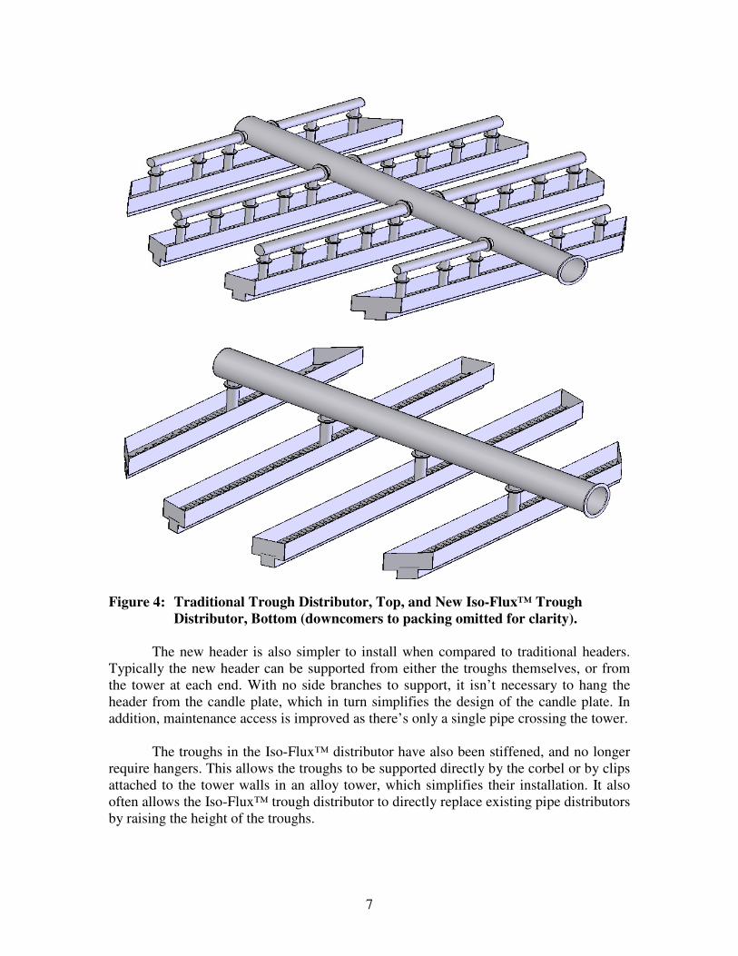
The most significant change in Chemetics’ new Iso-Flux™ trough distributor is
the simplified header. Figure 4 highlights the difference in headers between the previous
distributor design and the new Iso-Flux™ trough distributor. The new distributor requires
only a single inlet per trough, regardless of the tower size. In comparison, a large
distributor of Chemetics’ previous design could require over 10 inlets per trough.
Previously, a low acid inlet velocity was necessary to maintain a calm surface and
uniform acid distribution. The new design is able to provide a uniform acid distribution
and calm surface regardless of the inlet velocity. Using SARAMET®
allows for an
increase in the acid velocity within the trough without damaging the equipment.
Page 7
7
Figure 4: Traditional Trough Distributor, Top, and New Iso-Flux™ Trough
Distributor, Bottom (downcomers to packing omitted for clarity).
The new header is also simpler to install when compared to traditional headers.
Typically the new header can be supported from either the troughs themselves, or from
the tower at each end. With no side branches to support, it isn’t necessary to hang the
header from the candle plate, which in turn simplifies the design of the candle plate. In
addition, maintenance access is improved as there’s only a single pipe crossing the tower.
The troughs in the Iso-Flux™ distributor have also been stiffened, and no longer
require hangers. This allows the troughs to be supported directly by the corbel or by clips
attached to the tower walls in an alloy tower, which simplifies their installation. It also
often allows the Iso-Flux™ trough distributor to directly replace existing pipe distributors
by raising the height of the troughs.
Page 8
8
INTERNAL FEATURES
Chemetics’ new Iso-Flux™ trough distributor uses a combination of unique
internal features that work together to control the acid, distribute it evenly throughout the
trough, and prevent sedimentation from affecting the acid distribution. Figure 5 shows a
typical assembly of a trough, including the internal features. The calming plates,
deflectors, and screens separate the upper and lower sections of the trough while baffles
are located in the lower section of the trough. The subassemblies of calming plates,
deflectors, and screens are identical throughout the tower to simplify their manufacturing
and installation.
Figure 5: Iso-Flux™ Trough Assembly with Calming Plates, Deflectors, Screens,
Acid Inlet, and Downcomers (baffles in lower trough not visible).
Each calming plate assembly is bolted onto the distributor with the same bolts as
the downcomers, which simplifies the installation and minimizes the number of required
parts. The downcomers are welded to plates which are bolted onto the bottom of the
trough. This allows the distributor to fit through a manway into the tower, and also for the
downcomers to be replaced if necessary.
Calming Plate
Screen
Deflector
Acid Inlet Downcomer
Page 9
9
Figure 6: Internals of Assembled Iso-Flux™ Trough Distributor (acid inlet
removed for clarity)
CALMING PLATES AND DEFLECTORS
The calming plates and deflectors are primarily responsible for distributing the
acid along the length of the trough while maintaining a calm surface. The calming plates
separate each trough into an upper and lower section, as shown in Figure 6. The acid is
introduced to the trough in the lower section. It then travels along the lower section of the
trough, and is distributed into the upper section through regularly spaced openings. These
essentially transform the lower portion of the trough into an internal, integrated header.
The acid enters the upper section of the trough up through the openings in the calming
plates. The deflectors redirect the acid so that it travels horizontally in a fan around each
opening counter current to the flow in the lower section. This helps to maintain a calm,
uniform distribution along the length of each trough. In addition, the deflectors use the
Page 10
10
moving acid to stir the upper half of the trough, which prevents fine suspended solids
from falling out of suspension and accumulating around the exit orifices.
During full-scale testing, we tested the effectiveness of the deflectors to prevent
the accumulation of suspended solids. Plastic injection molding pellets were used because
of their comparable settling velocity to packing chips in acid. These pellets had a
diameter of approximately 4 mm, and were irregular in shape. They were poured directly
into the upper half of the distributor in multiple locations, and approximately 600 mL of
pellets were directly poured onto the calmest area in the trough. All the pellets were
removed in less than 10 seconds, validating the effectiveness of the design in preventing
sedimentation.
INTEGRATED SCREENS
Integrated screens, as shown in Figure 5, are located in each opening in the
calming plates. These screens are sized to prevent large pieces of packing chips, bricks,
and other debris from reaching the upper half of the trough where they could block the
exit orifices. During the sedimentation testing, significant quantities of solids were
introduced into the inlet of the distributor prior to start-up. The results showed that large
suspended solids tend to accumulate at the end of the troughs, where they do not affect
the acid distribution. The accumulated solids can be easily cleaned out during shutdowns
by removing the calming plates at the end of the trough.
Afterwards, we investigated the effects of clogging the screens in the calming
plate openings, even though we did not see substantial plugging in these screens during
testing. This was done by adding a significant quantity of solids to the liquid inlet, then
covering each opening with a piece of sheet metal and holding it in place with multiple
flanges. The combined represents a worst case scenario compared to the conditions seen
by real world acid plants. Surprisingly, the distributor still performed well, with a nearly
equal flow distribution through the exit orifices. The primary consequence was a
noticeable increase in surface turbulence. The integrated screens, in combination with the
deflectors effectively prevent suspended solids from degrading the distribution quality of
the distributor.
INTERNAL BAFFLES
Internal baffles are used to improve the distribution along the length of each
trough, and to prevent the acid from flowing preferentially along the bottom wall. When
the acid enters the distributor, it flows preferentially along the bottom of the distributor
which can cause poor liquid distribution near the inlet. Baffles in the inlet region detach
the acid flow from the bottom of the trough so that the flow is evenly distributed
throughout the lower section. In addition, baffles are located near the openings in the
calming plates to redirect a portion of the acid into the upper trough. The use of these
baffles greatly improves the acid distribution along the length of the trough.
Page 11
11
AIR GAP BETWEEN EXIT ORIFICES AND DOWNCOMERS
The Iso-Flux™ trough distributor uses an air gap to separate the exit orifices in
the trough from the downcomers, as shown in Figure 7. This air gap separates the flow
metering system (exit orifices) from the liquid distribution system (downcomers). By
doing so, each distribution point has its flow rate controlled only by the liquid level in the
upper trough and the size of the orifices. Resistance in the downcomers does not affect
the driving force in the metering system.
Figure 7: Side View of Trough Showing Air Gap between Exit Orifices and
Downcomers.
Occasionally, the air gap was a “leak path” in the former trough distributor
design. Packing chips could obstruct the exit orifices in the trough, which would re-direct
the acid horizontally. This would cause some of the acid to miss the downcomer, which
in turn would cause it to spray sideways into the gas stream. Although the majority of the
acid would fall to the packing, some droplets could be entrained in the gas stream where
they would be captured by the mist eliminators. In addition, if the acid was not entering
the downcomers then the distributor would not have a uniform distribution throughout the
tower. In order to assure that the acid always enters the downcomers, three major
improvements have been made in the new Iso-Flux™ distributor design. First, the
combination of screens and deflectors prevents sedimentation from blocking the exit
orifices. Second, the height of the air gap has been decreased. Finally, the downcomers
are designed to be oversized with respect to the exit orifices, so that even if the acid
leaves the exit orifice traveling somewhat horizontally, it will still enter the downcomer.
The downcomers serve two purposes: First, they transfer the acid away from the
trough so that it can be distributed onto the packing in a uniform pattern. Second, they
allow for each distribution point to have its own independent static head within the
downcomer tube. This is important, as the packing tends to block the exits of the
downcomers. In experiments, Chemetics found that the average downcomer had its open
area blocked by 15%, while 1 in 10 of the downcomers was more than 40% blocked. In
addition, deviations in downcomer length and height can affect the flow rate through the
downcomer. With the Iso-Flux™ design, each downcomer receives an identical amount
of flow set by an exit orifice located above. As the amount of blockage at the exit of each
downcomer varies, the height of the acid within each downcomer adapts so that the flow
rate remains constant. These downcomers are designed to handle at least an 80%
blockage without any change in the flow rate per distribution point. Most existing trough
distributor designs do not have an air gap or other means to separate the flow control
Trough
Air Gap
Downcomer
Exit Orifice
Page 12
12
orifices from the downcomers. This causes the flow distribution to be directly and
significantly effected by the conditions at the downcomer exit, which causes a less
predictable, more random, and lower quality distribution throughout the tower.
COMPARISON BETWEEN WEIRS AND ORIFICES
There are two main methods of flow control in acid distributors: weirs and
orifices. Each method has its strengths and weaknesses.
With weirs, a small change in surface height can cause a large change in flow
rate. This allows a weir based distributor to have a large turn-down ratio, but any
variations in height between the liquid surface and the bottom of the weirs can cause
large variations in the flow rate between distribution points. Because of this, weir based
distributors require tight manufacturing tolerances, careful leveling, a very calm liquid
surface, and a uniform liquid level throughout the distributor to maintain a uniform
distribution. Even the sag in the middle of a simply supported trough can cause a
substantial variation in the flow rates between distribution points.
In comparison, orifices are not as sensitive to surface height variations. This limits
turndown, but improves the uniformity of the distribution. In addition, they are simpler to
manufacture, and are always at the same elevation within the trough. In an orifice based
distributor, changes in the acid surface height can be used to diagnose flow issues. An
increase in surface height can be a sign that the orifices may be clogged, or that more
flow is going to the trough than expected. In a weir based distributor, the change in
surface height would be less obvious.
In general, weirs are less susceptible to clogging from suspended solids than
orifices. However, Chemetics’ new Iso-Flux™ trough distributor’s screens and deflectors
prevent suspended solids from blocking the orifices. Chemetics chose to use orifices over
weirs because they are less sensitive to surface height variations, easier to manufacture,
and useful for diagnosing flow problems. Although weirs do not have the same
sedimentation challenges as orifices, they make it more difficult to diagnose any flow
problems, are more expensive, and are more likely to have varying flow rates. It was
determined that we could more reliably address the sedimentation issues of orifices than
the distribution issues of weirs.
SUMMARY
Chemetics was able to simplify and improve upon its former trough distributor
design. The new Iso-Flux™ Trough Distributor has a simplified header, unique internal
geometry, and maintains the best features of Chemetics’ original trough distributor. The
simplified header reduces the overall cost, lead time, and installation time while
improving maintenance access. The unique internal geometry makes the Iso-Flux™
distributor highly resistant to sedimentation while providing a uniform acid distribution
throughout the tower. An air gap between the exit orifices and the downcomers ensures
Page 13
13
that each distribution point has the same flow rate. The combination of these features
makes Chemetics’ new Iso-Flux™ trough distributor a reliable, affordable, high quality
distributor well suited for the conditions found in real world acid plants.


![Drept Saramet proiect ghid 15.10 - unitbv.ro...&ypizevhyp )vsmpsv ] &ve csz 8ip je\ ` mrjs$yrmxfz vs ` [[[ yrmxfz vs î 'ytvmrw 1sxmzevi t](https://static.documents.pub/doc/80x56/60bbb77700e6d11467238af9/drept-saramet-proiect-ghid-1510-ypizevhyp-vsmpsv-ve-csz-8ip.jpg)


