Journal of Sedimentary Research, 2013, v. 83, 145–169 Research Article DOI: 10.2110/jsr.2013.8 MODEST CHANGE IN FLUVIAL STYLE WITH VARYING ACCOMMODATION IN REGRESSIVE ALLUVIAL- TO-COASTAL-PLAIN WEDGE: UPPER CRETACEOUS BLACKHAWK FORMATION, WASATCH PLATEAU, CENTRAL UTAH, U.S.A. GARY J. HAMPSON, 1 THOMAS O. JEWELL ,* 1 NAWAZISH IRFAN, {1 M. ROYHAN GANI, 2 AND BRYAN BRACKEN 3 1 Department of Earth Science and Engineering, Imperial College London, South Kensington Campus, London SW7 2AZ, U.K. , 2 Department of Earth and Environmental Sciences, University of New Orleans, 2000 Lakeshore Drive, New Orleans, Louisiana 70148, U.S.A. 3 Chevron Energy Technology Company, 6001 Bollinger Canyon Road, San Ramon, California 94583-0719, U.S.A. e-mail: [email protected]ABSTRACT: Concept-driven sequence stratigraphic models of alluvial-to-coastal-plain successions suggest that fluvial architecture and style should transition from isolated, single-story, channelized sandbodies deposited by single-thread (typically meandering) rivers in mudstone-prone, high-accommodation intervals into densely stacked, amalgamated sandbodies deposited by multiple-thread (typically braided) rivers in low-accommodation intervals. Model predictions of changing fluvial style are tested by comparing the facies character, internal architecture, dimensions, and formative paleohydraulic conditions of representative, major fluvial sandbodies developed at different stratigraphic levels of an alluvial-to-coastal-plain succession developed under a progressively decreasing rate of accommodation creation (Late Cretaceous Blackhawk Formation, Wasatch Plateau, central Utah, USA). The major fluvial sandbodies have a similar facies composition, and consist mainly of cross-bedded, medium-grained sandstone with subordinate mudclast conglomerate, folded sandstone, and inclined sandstones and intercalated siltstones. Facies are arranged within a hierarchy of architectural components. Channel stories (mean width and depth of 90 m and 7.2 m, respectively) represent the migration of a paleochannel segment and adjacent bar, and they are amalgamated laterally into channel belts (mean width and depth of 400 m and 9.2 m, respectively) that in turn are stacked vertically into channel-belt complexes (mean width and depth of 400 m and 20 m, respectively). Channel stories and belts were deposited by a combination of three paleochannel types that occur together in most major sandbodies: (1) single-thread ‘‘cut-and-fill’’ channels; (2) single- thread, laterally accreting channels of low-to-moderate sinuosity; and (3) multiple-thread, wandering-to-braided channels. Estimated paleochannel slopes are uniformly low (, 0.04u), most sandbodies contain sparse, potential marine indicators (e.g., Teredolites-bored logs and tidally modulated? carbonaceous drapes along cross-bed foresets), and paleodischarge estimates imply that multiple-thread channels may have narrowed and branched downstream to form distributary networks. All of these features are consistent with a delta-plain setting. Channel story and belt stacking patterns within each major sandbody (channel-belt complex) are highly non-uniform, such that (1) there are no systematic trends shared by the sandbodies, (2) sandbodies do not result from systematic, short-term changes in accommodation, such as those associated with the incision and fill of coastal incised valleys, and (3) variability within each sandbody is more pronounced than variability between sandbodies. These results suggest that local variations in sediment flux and transport capacity, combined with local avulsion history, were the principal controls on the architecture and dimensions of the major sandbodies. The similarities in architecture between major fluvial sandbodies imply that these controls were not predominantly governed by proximity to the coeval shoreline (c. 40–100 km) or by long-term tectonic subsidence rate (c. 80–700 m/Myr), which controlled creation of accommodation. INTRODUCTION Current sequence stratigraphic models of alluvial-to-coastal-plain successions (Wright and Marriott 1993; Shanley and McCabe 1994; Richards 1996) suggest that fluvial style should vary predictably within unconformity-bounded sequences. Sequence boundaries characterized by incision and well-developed interfluve paleosols are overlain by amal- gamated, multiple-thread (typically braided) channel sandbodies in the lowstand systems tract and isolated, single-story, single-thread (typically meandering) channel sandbodies in the transgressive and highstand systems tracts. The transition between transgressive and highstand systems tracts (cf. maximum flooding surface) may be marked by subtle marine influence (Shanley et al. 1992) or by coal-prone successions (e.g., Cross 1988; Bohacs and Suter 1997). These changes in fluvial style are interpreted to be driven by various allogenic controls on base level and * Present Address: Neftex Petroleum Consultants Limited, 97 Milton Park (second floor), Abingdon, Oxfordshire OX14 4RY, U.K. { Present Address: Pakistan Petroleum Limited, Exploration Department, House No. 59/A, Ismail Zabeeh Road, Faisal Avenue, F-8/4, Islamabad, Pakistan Published Online: February 2013 Copyright E 2013, SEPM (Society for Sedimentary Geology) 1527-1404/13/145-169/$03.00
Transcript
Journal of Sedimentary Research, 2013, v. 83, 145–169
Research Article
DOI: 10.2110/jsr.2013.8
MODEST CHANGE IN FLUVIAL STYLE WITH VARYING ACCOMMODATION IN REGRESSIVE ALLUVIAL-TO-COASTAL-PLAIN WEDGE: UPPER CRETACEOUS BLACKHAWK FORMATION, WASATCH PLATEAU,
CENTRAL UTAH, U.S.A.
GARY J. HAMPSON,1 THOMAS O. JEWELL,*1 NAWAZISH IRFAN,{1 M. ROYHAN GANI,2 AND BRYAN BRACKEN3
1Department of Earth Science and Engineering, Imperial College London, South Kensington Campus, London SW7 2AZ, U.K.
, 2Department of Earth and Environmental Sciences, University of New Orleans, 2000 Lakeshore Drive, New Orleans, Louisiana 70148, U.S.A.3Chevron Energy Technology Company, 6001 Bollinger Canyon Road, San Ramon, California 94583-0719, U.S.A.
ABSTRACT: Concept-driven sequence stratigraphic models of alluvial-to-coastal-plain successions suggest that fluvialarchitecture and style should transition from isolated, single-story, channelized sandbodies deposited by single-thread(typically meandering) rivers in mudstone-prone, high-accommodation intervals into densely stacked, amalgamated sandbodiesdeposited by multiple-thread (typically braided) rivers in low-accommodation intervals. Model predictions of changing fluvialstyle are tested by comparing the facies character, internal architecture, dimensions, and formative paleohydraulic conditions ofrepresentative, major fluvial sandbodies developed at different stratigraphic levels of an alluvial-to-coastal-plain successiondeveloped under a progressively decreasing rate of accommodation creation (Late Cretaceous Blackhawk Formation, WasatchPlateau, central Utah, USA).The major fluvial sandbodies have a similar facies composition, and consist mainly of cross-bedded, medium-grained
sandstone with subordinate mudclast conglomerate, folded sandstone, and inclined sandstones and intercalated siltstones.Facies are arranged within a hierarchy of architectural components. Channel stories (mean width and depth of 90 m and 7.2 m,respectively) represent the migration of a paleochannel segment and adjacent bar, and they are amalgamated laterally intochannel belts (mean width and depth of 400 m and 9.2 m, respectively) that in turn are stacked vertically into channel-beltcomplexes (mean width and depth of 400 m and 20 m, respectively). Channel stories and belts were deposited by a combinationof three paleochannel types that occur together in most major sandbodies: (1) single-thread ‘‘cut-and-fill’’ channels; (2) single-thread, laterally accreting channels of low-to-moderate sinuosity; and (3) multiple-thread, wandering-to-braided channels.Estimated paleochannel slopes are uniformly low (, 0.04u), most sandbodies contain sparse, potential marine indicators (e.g.,Teredolites-bored logs and tidally modulated? carbonaceous drapes along cross-bed foresets), and paleodischarge estimatesimply that multiple-thread channels may have narrowed and branched downstream to form distributary networks. All of thesefeatures are consistent with a delta-plain setting.Channel story and belt stacking patterns within each major sandbody (channel-belt complex) are highly non-uniform, such
that (1) there are no systematic trends shared by the sandbodies, (2) sandbodies do not result from systematic, short-termchanges in accommodation, such as those associated with the incision and fill of coastal incised valleys, and (3) variabilitywithin each sandbody is more pronounced than variability between sandbodies. These results suggest that local variations insediment flux and transport capacity, combined with local avulsion history, were the principal controls on the architecture anddimensions of the major sandbodies. The similarities in architecture between major fluvial sandbodies imply that these controlswere not predominantly governed by proximity to the coeval shoreline (c. 40–100 km) or by long-term tectonic subsidence rate(c. 80–700 m/Myr), which controlled creation of accommodation.
INTRODUCTION
Current sequence stratigraphic models of alluvial-to-coastal-plainsuccessions (Wright and Marriott 1993; Shanley and McCabe 1994;Richards 1996) suggest that fluvial style should vary predictably within
unconformity-bounded sequences. Sequence boundaries characterized byincision and well-developed interfluve paleosols are overlain by amal-gamated, multiple-thread (typically braided) channel sandbodies in thelowstand systems tract and isolated, single-story, single-thread (typicallymeandering) channel sandbodies in the transgressive and highstandsystems tracts. The transition between transgressive and highstandsystems tracts (cf. maximum flooding surface) may be marked by subtlemarine influence (Shanley et al. 1992) or by coal-prone successions (e.g.,Cross 1988; Bohacs and Suter 1997). These changes in fluvial style areinterpreted to be driven by various allogenic controls on base level and
* Present Address: Neftex Petroleum Consultants Limited, 97 Milton Park
Copyright E 2013, SEPM (Society for Sedimentary Geology) 1527-1404/13/145-169/$03.00
sediment flux, including relative sea level, basin subsidence, climate, andhinterland tectonism (e.g., Shanley and McCabe 1994; Holbrook et al.2006). Geomorphic studies of modern rivers and floodplains, and physicalexperiments and numerical models imply that stratigraphic architecturesdriven by allogenic controls may be substantially modified or overprintedby the autogenic response(s) of fluvial systems, such as avulsion, to thesecontrols (e.g., Westcott 1993; Mackey and Bridge 1995; Jerolmack andPaola 2007; Sheets et al. 2007; Hajek et al. 2010; Wang et al. 2011).
The alluvial-to-coastal-plain strata of the Cretaceous BlackhawkFormation, Wasatch Plateau, central Utah, offer an important testagainst a high-quality outcrop dataset of both sequence stratigraphic andavulsion-based models of fluvial style and stratigraphic architecture.These strata form part of a progradational siliciclastic wedge whoseshallow-marine component has been extensively studied in the nearbyBook Cliffs (e.g., Balsley 1980). Here, the shallow-marine BlackhawkFormation is interpreted to contain multiple high-frequency sequences ofc. 0.2–1.0 Myr duration stacked within a low-frequency highstandsystems tract of c. 2.0–3.0 Myr duration (Fig. 2) (e.g., Howell and Flint2003; Hampson 2010 and references therein). The Blackhawk Formationis overlain by the Castlegate Sandstone across a regional erosion surface,interpreted as a major, low-frequency sequence boundary (e.g., VanWagoner 1995), which is associated with angular truncation in thewesternmost Book Cliffs (Yoshida et al. 1996; Miall and Arush 2001) andpotentially also in the Wasatch Plateau (Hampson et al. 2012). Recentmapping of large-scale stratigraphic architecture and sandbody distribu-tions in the alluvial-to-coastal-plain Blackhawk Formation of theWasatch Plateau indicates that stratigraphic organization of the typeimplied by sequence stratigraphic models is rare and cryptic (Hampsonet al. 2012). In the lower c. 50 m of the Blackhawk Formation, strati-graphic cycles bounded by major, regionally extensive coal zones areidentified. The coal zones correspond to parasequence-bounding floodingsurfaces in coeval shallow-marine strata (e.g., Flores et al. 1984; Dubielet al. 2000; Hampson et al. 2011), implying that the stratigraphic cyclescan be attributed to cyclic, high-frequency (, 0.1 Myr duration) relativesea-level changes (Hampson et al. 2012). Similar coal zones andstratigraphic cycles are absent in the upper Blackhawk Formation. Inthe Wasatch Plateau as a whole, there are upward-increasing trends insandbody size and abundance from base to top of the BlackhawkFormation, consistent with the formation being assigned to a low-frequency (c. 2.0–3.0 Myr duration) highstand systems tract in coevalshallow-marine strata. There is also an abrupt increase in sandbodyabundance and amalgamation across the base of the CastlegateSandstone, consistent with the interpretation of this contact as a majorsequence boundary. Adams and Bhattacharya (2005) documented thatfluvial style was uniform in the uppermost Blackhawk Formation andCastlegate Sandstone. However, no work has been carried out to date onthe facies character and internal architectures of fluvial sandbodies in theremainder of the Blackhawk Formation, and as a result their fluvial stylesand potential relationships with stratigraphic architecture are unknown.
The aims of the paper are threefold: (1) to document the faciescharacter and internal architectures of representative fluvial sandbodiesdeveloped at a number of stratigraphic levels throughout the BlackhawkFormation, (2) to reconstruct the plan-view morphology and fluvial styleof the Blackhawk rivers, and (3) to evaluate controls on fluvial style andalluvial-to-coastal-plain stratigraphic architecture in the BlackhawkFormation. The results have broad applications to our understandingof alluvial-to-coastal-plain rivers and their preservation in the strati-graphic record, and specific applications to predicting hydrocarbonrecovery from alluvial-to-coastal-plain reservoirs. Sandbody connectivityand reservoir drainage are strongly controlled by the spatial organizationof fluvial sandbodies (e.g., Larue and Hovadik 2006), hence it isimportant to establish the degree to which such organization can berelated to fluvial style.
STRATIGRAPHIC AND PALEOGEOGRAPHIC SETTING
The studied alluvial-to-coastal-plain strata lie within the nonmarineBlackhawk Formation, which was deposited along the western margin ofthe Cretaceous North American Western Interior Seaway (e.g., Krystinikand DeJarnett 1995; inset map in Fig. 1). The nonmarine BlackhawkFormation overlies and interfingers to the east with shallow-marinesandstones of the Star Point Sandstone and various shallow-marinemembers of the Blackhawk Formation, and it underlies fluvial sandstonesof the lower Castlegate Sandstone (Fig. 2; Spieker and Reeside 1925;Young 1955). In combination, these lithostratigraphic units form aneastward-thinning siliciclastic wedge of early and middle Campanian age(Fouch et al. 1983) that passes basinward into the offshore deposits of theMancos Shale (Young 1955) and represents a duration of 3.5–4.0 Myr(Krystinik and DeJarnett 1995). The sediment within this wedge wasderived from the Sevier Orogen (Fig. 1), probably from the CanyonRange Culmination c. 80 km west of the Wasatch Plateau outcrop belt(DeCelles and Coogan 2006). The study area lay within the flexurallysubsiding foredeep of the Sevier Orogen, but also experienced subsidencedriven by dynamic topography across the entire seaway (e.g., Liu andNummedal 2004). It occupied a paleolatitude of approximately 42u N(Kauffman and Caldwell 1993), and flora from the nonmarine BlackhawkFormation indicate that the climate was seasonal and warm temperate tosubtropical (Parker 1976).
Most previous work on the nonmarine Blackhawk Formation hasfocused on characterizing coal resources in the Wasatch Plateau coalfield(e.g., Spieker 1931; Doelling 1972; Hayes and Sanchez 1979; Sanchez etal. 1983; Dubiel et al. 2000; Quick et al. 2005). Coal seams are thickestand most abundant in the lower part of the Blackhawk Formation, wherethey define a high-resolution stratigraphic framework (e.g., Flores et al.1984; Dubiel et al. 2000; Hampson et al. 2012). However, most of theBlackhawk Formation consists of a variety of channelized fluvial andsheet-like crevasse-splay sandbodies surrounded by floodplain shales,supplemented by lagoonal shales in the lower part of the formation(Marley et al. 1979; Flores et al. 1984; Hampson et al. 2012). Thesedeposits represent an overall alluvial-to-coastal-plain setting that laybehind a series of approximately north–south-trending, wave-dominatedshorelines represented by the Star Point Sandstone in the WasatchPlateau (Figs. 1, 2) (Flores et al. 1984; Dubiel et al. 2000; Hampson et al.2011) and shallow-marine members of the Blackhawk Formation in theBook Cliffs (Fig. 1) (e.g., Balsley 1980; Hampson and Howell 2005).
Both regionally, across the eastern Wasatch Plateau (over an area of1500 km2), and locally, in the 150 km2 area surrounding Link Canyon,channelized fluvial sandbodies increase in size and abundance from thebase to the top of the Blackhawk Formation (Marley et al. 1979;Hampson et al. 2012). The regional proportion of channelized sandbodiesvaries from c. 10% in the lower Blackhawk Formation to c. 30% in theupper Blackhawk Formation (Hampson et al. 2012), and then increasesabruptly to. 90% in the lower Castlegate Sandstone (Miall 1993; Adamsand Bhattacharya 2005; McLaurin and Steel 2007; Hajek and Heller2012). The upward increase in sandbody abundance coincides with adecrease in tectonic subsidence rate during deposition of the upperBlackhawk Formation and lower Castlegate Sandstone, inferred from aprogressive decrease in aggradation rate of shallow-marine strata in theBlackhawk–Castlegate clastic wedge (based on regional outcrop andsubsurface mapping tied to dated ammonite biozones; Hampson 2010),and with a progressive increase in distance from the coeval shoreline(Fig. 2) (based on regional mapping at outcrop of successive shorelines inthe Star Point Sandstone and Blackhawk Formation; e.g., Kamola andHuntoon 1995; Taylor and Lovell 1995; Hampson 2010; Hampson et al.2011). Sequence stratigraphic interpretations in the Book Cliffs assign theBlackhawk Formation to a low-frequency highstand systems tract (c. 2.0–3.0 Myr duration) truncated by a sequence boundary at the base of the
146 G.J. HAMPSON ET AL. J S R
lower Castlegate Sandstone, which constitutes a low-frequency lowstandsystems tract (Taylor and Lovell 1995; Van Wagoner 1995; Yoshida 2000;Howell and Flint 2003). Multiple high-frequency sequences (c. 0.2–1.0 Myr duration) are superimposed on the low-frequency highstand andlowstand systems tracts (e.g., Van Wagoner 1995; Yoshida 2000; Howelland Flint 2003; Hampson 2010). Detailed architectural analysis in an areasouth of Link Canyon (labeled Salina Canyon in Figs. 1, 2) suggests thatfluvial sandbodies in the uppermost Blackhawk Formation weredeposited by braided river systems of style similar to those that formedthe overlying Castlegate Sandstone, but sandbodies in the latter are muchmore strongly amalgamated (Adams and Bhattacharya 2005), supportinga reduction in accommodation across a low-frequency sequenceboundary at the base of the Castlegate Sandstone. Detailed architecturalanalyses of the lower Castlegate Sandstone in the Book Cliffs suggest thatthe bedload-dominated braided river channels deepened downstream(Miall 1993, 1994) and then transitioned to a bedload-starved,distributive channel network close to the shoreline (Petter 2010). Todate, there has been no systematic architectural analysis of fluvialsandbodies in the Blackhawk Formation, and the origin(s) of theincreasing-upward trend in sandbody size within it is uncertain.
DATASET AND METHODS
Up to 300 m of alluvial-to-coastal-plain strata in the BlackhawkFormation are exposed in a laterally extensive (c. 100 km), nearlycontinuous cliff face along the eastern edge of the Wasatch Plateau incentral Utah (Fig. 1, 2). The cliff face is oriented SSW–NNE, oblique to theregional depositional strike of coeval wave-dominated deltaic shorelines inthe Star Point Sandstone, Wasatch Plateau (Flores et al. 1984; Dubiel et al.2000; Hampson et al. 2011) and shallow-marinemembers of the BlackhawkFormation, Book Cliffs (e.g., Balsley 1980; Hampson andHowell 2005 andreferences therein). Within the context of a well established coal-zonestratigraphy (e.g., Spieker 1931; Doelling 1972; Hayes and Sanchez 1979;Sanchez et al. 1983; Dubiel et al. 2000), the gross stratigraphic architectureof Blackhawk Formation alluvial-to-coastal-plain deposits has recently
been characterized using oblique aerial photos and LIDAR data, combinedwith measured sections at accessible locations (Hampson et al. 2012;Rittersbacher et al. in press). This work provides the context for the datasetof the present study, which was collected from an easily accessible‘‘window’’ of the cliff face around Link Canyon (Fig. 3), in the southernpart of outcrop belt (Fig. 1). The cliff-face geometry around Link Canyonprovides some three-dimensional control on the exposed stratigraphicarchitecture (Fig. 3B).
The dataset comprises 21 measured sections and a comprehensive set ofhigh-resolution photomontages collected from six major sandbodies andthree minor sandbodies developed at different stratigraphic levels withinthe Blackhawk Formation (major sandbodies are numbered 1–6 in Fig. 3;minor sandbodies lie below major sandbody 5). The measured sectionsrecord lithology, grain size and sorting, sedimentary structures, paleo-currents, body fossils, and trace fossils, and they have been studied usingconventional facies analysis. Photomontages have been used to constructbedding diagrams that have enabled identification of a hierarchy ofarchitectural units and their bounding surfaces within each sandbody (cf.architectural-element analysis of Miall 1985, 1988 and Holbrook 2001).Maps of the sandbodies and their constituent architectural units havebeen constructed by combining architectural panels in various orienta-tions around the canyon.
FACIES ANALYSIS
Seven facies have been identified in the studied sandbodies andsurrounding fine-grained deposits (Table 1). In combination, these faciesbelong to two facies associations documented in previous work on the grossstratigraphic architecture of the Blackhawk Formation (Fluvial Sandbodiesand Aggradational Floodplain facies associations of Hampson et al. 2012).
Fluvial Sandbodies Facies Association
The fluvial sandbodies facies association of Hampson et al. (2012)consists of laterally discontinuous, erosionally based, channelized
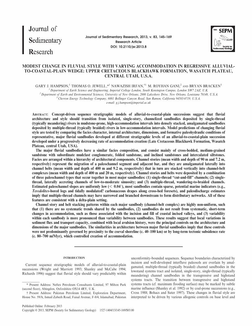
FIG. 1.—Location map showing the StarPoint Sandstone, Blackhawk Formation, andCastlegate Sandstone outcrop belt in the Wa-satch Plateau and contiguous Book Cliffs. Theposition of a regional stratigraphic cross section(Fig. 2) and the Link Canyon study area (Fig. 3)are highlighted. Previous studies of fluvial-sandbody architecture have been carried out onthe Castlegate Sandstone at Salina Canyon (SC),Joes Valley (JV), and the Castle Gate (CG)(Miall 1993; Adams and Bhattacharya 2005;McLaurin and Steel 2007; Hajek and Heller2012), and on the uppermost Blackhawk For-mation at Salina Canyon (SC) (Adams andBhattacharya 2005). The position of tectonicfeatures that influenced geomorphology, drain-age and sediment supply from the Sevier Orogenduring deposition of the Blackhawk Formationand Castlegate Sandstone are shown (afterJohnson 2003; Horton et al. 2004; DeCelles andCoogan 2006). The positions of selected StarPoint and Blackhawk shorelines, whose strati-graphic position is shown in Figure 2, areindicated by circled numbers 3, 7, 9, 10, 11, and12 (after Kamola and Huntoon 1995; Taylor andLovell 1995; Hampson 2010; Hampson et al.2011). The inset map (top right) shows thelocation of the outcrop belt map on the westernmargin of the Late Cretaceous Western InteriorSeaway (after Kauffman and Caldwell 1993).
MODEST CHANGE IN FLUVIAL STYLE WITHIN REGRESSIVE CLASTIC WEDGE 147J S R
sandbodies of variable dimensions (5–25 m thick, 50–6000 m wide overthe entire Wasatch Plateau outcrop belt). The association has fourconstituent facies (F1–F4), and corresponds to the Type III sandstones ofMarley et al. (1979).
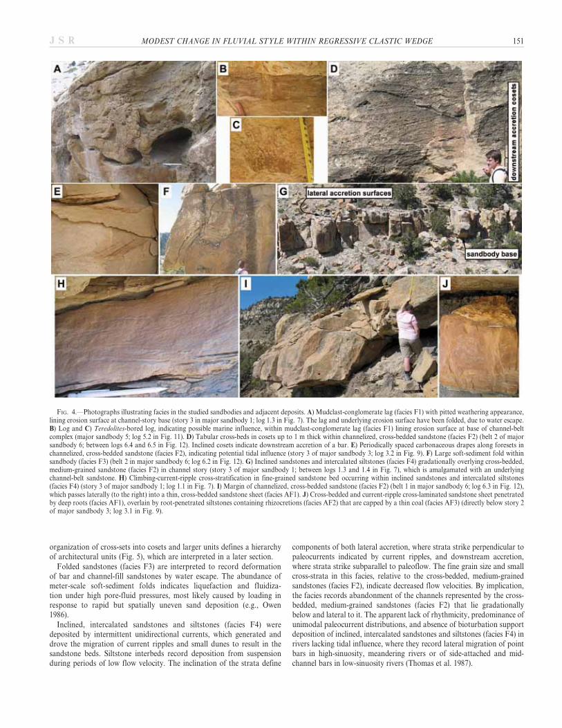
Description.—Prominent erosion surfaces within and at the base ofchannelized sandbodies are lined by thin (, 1 m), laterally discontinuous(, 50 m) sheets of moderately to poorly sorted, medium- to coarse-grained sandstone containing abundant rounded mudclasts, and woodand carbonaceous plant fragments (facies F1; Fig. 4A–C). Some woodfragments contain Teredolites borings (Fig. 4C). These mudclast con-glomerates constitute only a small proportion (, 5%) of the totalsandbody volume.
Mudclast conglomerates (facies F1) are overlain by moderately sorted,medium-grained sandstones containing abundant trough and tabularcross-bedding, with subordinate planar-parallel lamination and struc-tureless beds (facies F2; Fig. 4D). Cross-bedded, medium-grainedsandstones contain minor intercalations of fine-grained sandstone andsiltstones, but lack upward-fining or upward-coarsening trends. They
occur as channelized and lenticular bodies up to 6.0 m thick and 200 mwide. Scattered mudclasts are present along cross-set bases and foresets,and carbonaceous drapes occur along the foresets and toesets of a smallnumber of cross-sets (Fig. 4E). Cross-sets are up to 1.0 m thick, and arestacked into cosets that are 0.8–3.0 m thick. Cross-set boundaries in somecosets dip in the same direction as foresets within the constituent cross-sets (Fig. 4D), whereas in others they are horizontal or inclined nearlyperpendicular to foreset dip. Cosets are arranged into larger architecturalunits, which have a range of internal organizations and are bounded byerosion surfaces, some lined by mudstone conglomerates (facies F1).Cross-bedded, medium-grained sandstones constitute most (70–95%) ofthe total volume of the major sandbodies (numbered 1–6 in Fig. 3) butare absent in some minor sandbodies (not shown in Fig. 3, but locatedbelow major sandbody 5).
Mudclast conglomerates (facies F1) and cross-bedded, medium-grainedsandstones (facies F2) enclose regions of moderately sorted, medium-grained sandstone characterized by meter-scale soft-sediment folds (faciesF3; Fig. 4F). These deformed, folded regions have highly variablegeometry, and are up to 3.5 m thick and 20 m wide. They constitute a
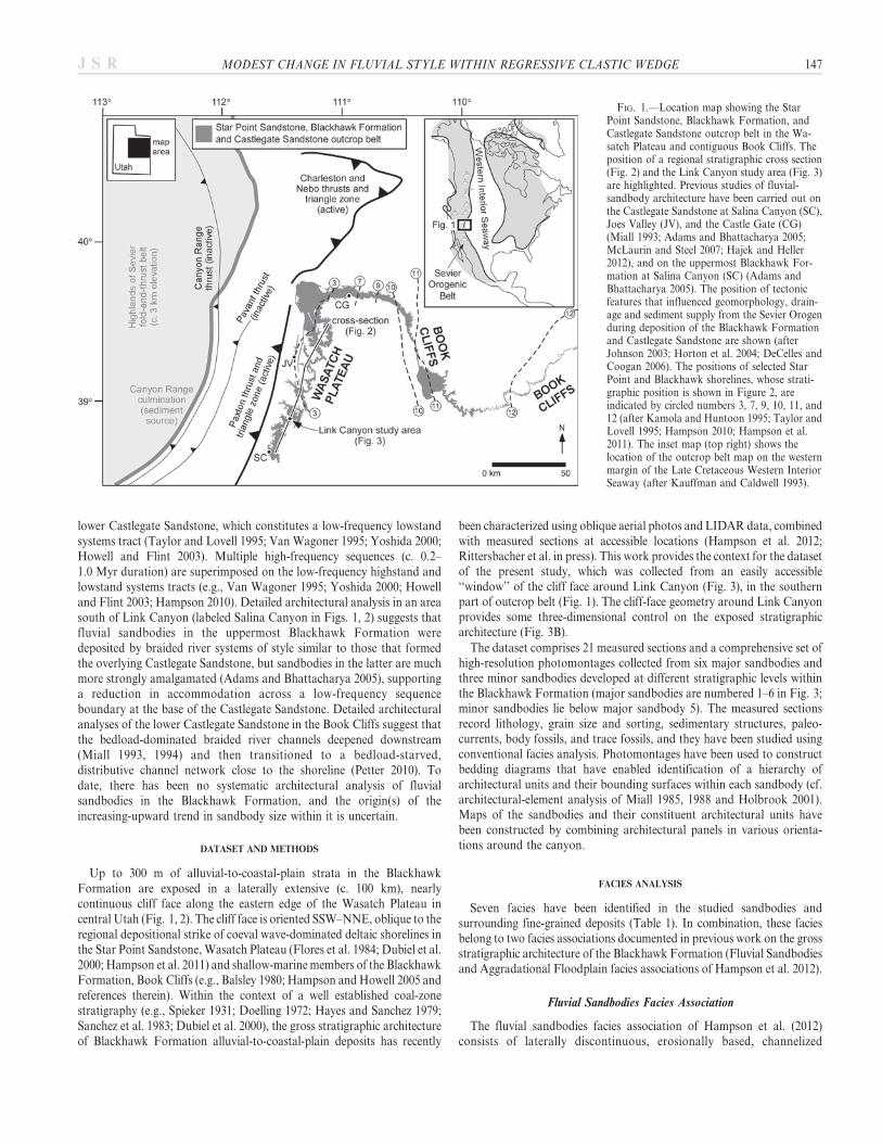
FIG. 2.—Cross section summarizing stratigraphic architectures and large-scale patterns of sandbody distribution in the Blackhawk Formation outcrop belt of theWasatch Plateau (Fig. 1), combined with key parameters that constrain its regional context: distance from coeval shoreline, distance from sediment source, and sedimentaccumulation rate (after Hampson et al. 2011, 2012). Shoreline positions are numbered sequentially from 1 to 12, corresponding to maximum regression forparasequences in the Star Point Sandstone (1 5 KSp040, 2 5 KSp030, 3 5 KSp020, 4 5 KSp010: Hampson et al. 2011), Spring Canyon Member (5 5 SC4,6 5 SC5, 7 5 SC7: after Kamola and Huntoon 1995), Aberdeen Member (8 5 A1, 9 5 A4: after Kamola and Huntoon 1995), Kenilworth Member (10 5 K1,11 5 K4; after Taylor and Lovell 1995), and Castlegate Sandstone (12 5 C3; Hampson 2010). The mapped extents of shorelines 3, 7, 9, 10, 11, and 12 are shown inFigure 1.
148 G.J. HAMPSON ET AL. J S R
small proportion (, 5% to 20%) of the total volume of any particularsandbody.In several sandbodies, cross-bedded, medium-grained sandstones (facies
F2) pass gradationally upward and laterally into upward-fining successionsof moderately sorted, medium- to fine-grained sandstone beds andintercalated siltstones (facies F4; upper part of sandbody, containingprominent inclined surfaces, in Fig. 4G). Sandstone beds in these lattersuccessions are predominantly current-ripple cross-stratified and planar-parallel laminated, with some thin (, 0.3 m) cross-beds (Fig. 4H). Cross-stratification is unidirectional, and paleocurrents have a unimodaldistribution. Siltstones thicken and become more abundant upward(Fig. 4G), with no apparent rhythmicity. Intercalated sandstones andsiltstones (facies F4) are inclined at a low angle (, 20u), and strikesubparallel to perpendicular to paleocurrents indicated by current ripples.The tops of some successions are sparsely penetrated by rootlets. Inclined,intercalated sandstones and siltstones form a small proportion (, 5% to20%) of the total volume of the major sandbodies (numbered 1–6 in Fig. 3)but may constitute almost all (. 95%) of the total volume of minorsandbodies (not shown in Fig. 3, but located below major sandbody 5).
Interpretation.—The facies association as a whole is considered toconsist of the sandstone deposits of river channel systems in an alluvial-to-coastal-plain setting (Marley et al. 1979; Flores et al. 1984; Dubiel et al.
2000; Hampson et al. 2012; Rittersbacher et al. in press). In this context,mudstone conglomerates (facies F1) are interpreted as lag deposits liningerosion surfaces at the bases of channels and their constituentarchitectural elements (channel stories, bars and bar-growth incrementsin Figs. 5, 6). The abundance of mudstone clasts and wood fragmentsindicates erosion of a vegetated, cohesive, mudstone-rich substrate,represented by the aggradational floodplain facies association (faciesAF1–AF3). Where present, rare Teredolites-bored wood fragments(Fig. 4C) may indicate either marine or freshwater conditions, both ofwhich are consistent with the coastal-plain setting (e.g., Bromley et al.1984; Plint and Pickerill 1985).
Cross-bedded, medium-grained sandstones (facies F2) record deposi-tion from straight- and sinuous-crested dunes that migrated in responseto unidirectional currents. Carbonaceous drapes along the foresets andtoesets of a few cross-sets indicate settling of abundant carbonaceousflakes from suspension during periods of low flow velocity; where suchdrapes are organized periodically, they may indicate tidal influence (e.g.,Nio and Yang 1991). The stacking of cross-sets into cosets records thesuperposition of migrating dunes on to larger bars. The inclination ofcross-sets within cosets records downstream accretion of bars, where setboundaries are inclined in the same direction as foresets within cross-sets(Fig. 4D), or lateral-to-oblique bar accretion, where set boundaries areinclined nearly perpendicular to foreset dip (cf. Miall 1994). The
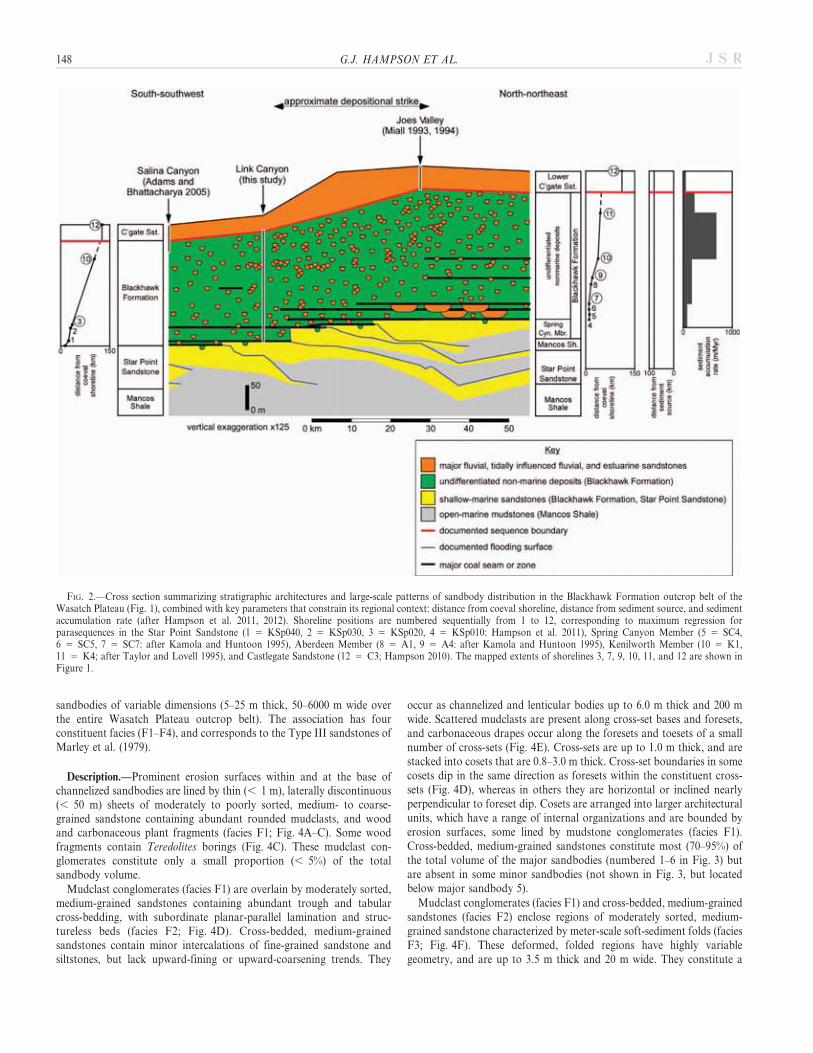
FIG. 3.—A) Panel showing mapped stratigraphy and facies architecture in the Blackhawk Formation along the cliff line around the Link Canyon study area (Figs. 1, 2,3B) (after Hampson et al. 2012). The Knight and Accord lakes coal zones in the lower Blackhawk Formation (after Hayes and Sanchez 1979; Sanchez et al. 1983) and theprojected positions of the Bear Canyon and Kenilworth–Castlegate D coal zones, which are used to subdivide the Blackhawk Formation into gross intervals (Hampson etal. 2012), are shown. B) Geologic map of the Link Canyon study area. Both the panel and the map highlight the positions of six major fluvial sandbodies, numbered 1–6,whose internal architecture has been characterized in this study.
MODEST CHANGE IN FLUVIAL STYLE WITHIN REGRESSIVE CLASTIC WEDGE 149J S R
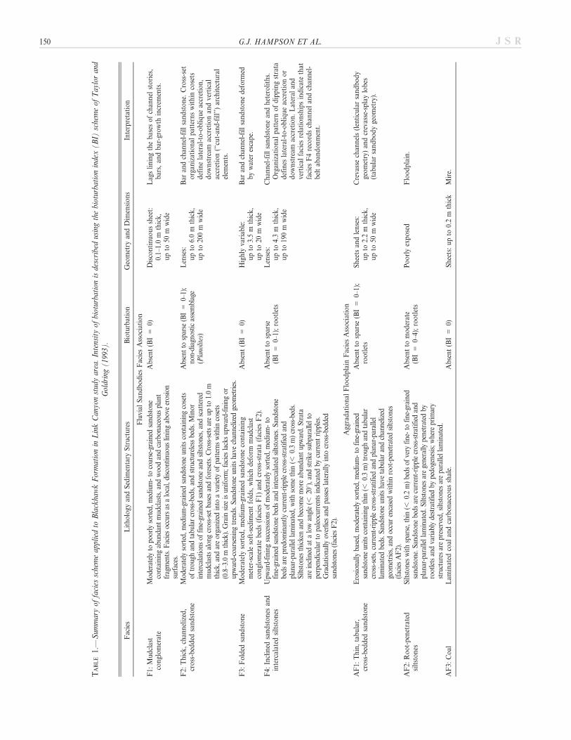
TABLE1.—
Sum
maryof
facies
schemeappliedto
BlackhawkFormationin
LinkCanyonstudyarea.Intensityof
bioturbation
isdescribedusingthebioturbation
index(B
I)schemeof
Taylorand
Goldring(1993).
Facies
Lithology
andSedim
entary
Structures
Bioturbation
Geometry
andDim
ensions
Interpretation
Fluvial
San
dbodiesFaciesAssociation
F1:
Mudclast
conglomerate
Mod
eratelyto
poorly
sorted,medium-to
coarse-grained
sand
ston
econtaining
abun
dant
mud
clasts,an
dwoo
dan
dcarbon
aceous
plant
fragments.Faciesoccurs
asalocal,discon
tinu
ouslin
ingab
oveerosion
surfaces.
Absent(BI5
0)Discontinuoussheet:
0.1–
1.0m
thick,
upto
50m
wide
Lag
sliningthebases
ofchan
nel
stories,
bars,an
dbar-growth
increm
ents.
F2:
Thick,chan
nelized,
cross-bedded
sandstone
Mod
eratelysorted,medium-grained
sand
ston
eun
itscontaining
cosets
oftrou
ghan
dtabu
larcross-beds,an
dstructurelessbeds.Minor
intercalations
offine-grained
sand
ston
ean
dsiltston
es,an
dscattered
mud
clastsalon
gcross-setbasesan
dforesets.Cross-setsareup
to1.0m
thick,
andareorganizedinto
avarietyof
patterns
withincosets
(0.8–3.0
mthick).Grain
size
isun
iform;facies
lacksup
ward-fining
orup
ward-coarsening
trends.Sa
ndston
eun
itsha
vechan
nelized
geom
etries.
Absentto
sparse
(BI5
0–1);
non-diagno
sticassemblage
(Planolites)
Lenses:
upto
6.0m
thick,
upto
200m
wide
Bar
andchan
nel-fillsandstone.
Cross-set
organ
izational
patternswithin
cosets
definelateral-to-obliqueaccretion,
downstream
accretionan
dvertical
accretion(‘‘cut-an
d-fill’’)architectural
elem
ents.
F3:
Folded
sandstone
Moderatelysorted,medium-grained
sandstonecontaining
meter-scale
soft-sedim
entfolds,whichdeform
mudclast
conglomeratebeds(faciesF1)
andcross-strata(faciesF2).
Absent(BI5
0)Highly
variab
le:
upto
3.5m
thick,
upto
20m
wide
Bar
andchan
nel-fillsandstonedeform
edbywater
escape.
F4:
Inclined
sandstones
and
intercalated
siltstones
Upw
ard-fining
succession
sof
mod
eratelysorted,medium-to
fine-grained
sand
ston
ebeds
andintercalated
siltston
es.Sa
ndston
ebeds
arepredom
inan
tlycurrent-ripp
lecross-stratified
and
plan
ar-parallellaminated,withsomethin
(,0.3m)cross-beds.
Siltston
esthickenandbecomemoreab
unda
ntup
ward.
Strata
areinclined
atalowan
gle(,
20u),an
dstrike
subp
arallelto
perpendicularto
paleocurrentsindicatedby
currentripp
les.
Gradation
ally
overliesan
dpa
sses
laterally
into
cross-bedd
edsand
ston
es(faciesF2).
Absentto
sparse
(BI5
0–1);rootlets
Lenses:
upto
4.3m
thick,
upto
190m
wide
Chan
nel-fillsandstonean
dheteroliths.
Organ
izational
pattern
ofdippingstrata
defines
lateral-to-obliqueaccretionor
downstream
accretion.Lateral
and
vertical
facies
relationshipsindicatethat
facies
F4recordschan
nel
andchan
nel-
beltab
andonment.
Agg
radational
Floodplain
FaciesAssociation
AF1:
Thin,tabular,
cross-bedded
sandstone
Erosion
ally
based,
mod
eratelysorted,medium-to
fine-grained
sand
ston
eun
itscontaining
thin
(,0.3m)trou
ghan
dtabu
lar
cross-sets,current-ripp
lecross-stratified
andplan
ar-parallel
laminated
beds.Sa
ndston
eun
itsha
vetabu
laran
dchannelized
geom
etries,an
doccurencasedwithinroot-penetratedsiltston
es(faciesAF2).
Absentto
sparse
(BI5
0–1);
rootlets
Sheets
andlenses:
upto
2.2m
thick,
upto
50m
wide
Creva
ssechan
nels(lenticularsandbody
geometry)an
dcrevasse-splaylobes
(tab
ularsandbodygeometry).
AF2:
Root-penetrated
siltstones
Siltston
eswithsparse,thin
(,0.2m)beds
ofvery
fine-to
fine-grained
sand
ston
e.Sa
ndston
ebeds
arecurrent-ripp
lecross-stratified
and
plan
ar-parallellaminated.Siltston
esaregenerally
penetrated
byrootletsan
dvariab
lydestratified
bypedo
genesis;where
prim
ary
structures
arepreserved,
siltston
esarepa
rallellaminated.
Absentto
moderate
(BI5
0–4);rootlets
Poorlyexposed
Floodplain.
AF3:
Coal
Lam
inated
coal
andcarbonaceousshale.
Absent(BI5
0)Sheets:upto
0.2m
thick
Mire.
150 G.J. HAMPSON ET AL. J S R
organization of cross-sets into cosets and larger units defines a hierarchyof architectural units (Fig. 5), which are interpreted in a later section.
Folded sandstones (facies F3) are interpreted to record deformationof bar and channel-fill sandstones by water escape. The abundance ofmeter-scale soft-sediment folds indicates liquefaction and fluidiza-tion under high pore-fluid pressures, most likely caused by loading inresponse to rapid but spatially uneven sand deposition (e.g., Owen1986).
Inclined, intercalated sandstones and siltstones (facies F4) weredeposited by intermittent unidirectional currents, which generated anddrove the migration of current ripples and small dunes to result in thesandstone beds. Siltstone interbeds record deposition from suspensionduring periods of low flow velocity. The inclination of the strata define
components of both lateral accretion, where strata strike perpendicular topaleocurrents indicated by current ripples, and downstream accretion,where strata strike subparallel to paleoflow. The fine grain size and smallcross-strata in this facies, relative to the cross-bedded, medium-grainedsandstones (facies F2), indicate decreased flow velocities. By implication,the facies records abandonment of the channels represented by the cross-bedded, medium-grained sandstones (facies F2) that lie gradationallybelow and lateral to it. The apparent lack of rhythmicity, predominance ofunimodal paleocurrent distributions, and absence of bioturbation supportdeposition of inclined, intercalated sandstones and siltstones (facies F4) inrivers lacking tidal influence, where they record lateral migration of pointbars in high-sinuosity, meandering rivers or of side-attached and mid-channel bars in low-sinuosity rivers (Thomas et al. 1987).
FIG. 4.—Photographs illustrating facies in the studied sandbodies and adjacent deposits. A) Mudclast-conglomerate lag (facies F1) with pitted weathering appearance,lining erosion surface at channel-story base (story 3 in major sandbody 1; log 1.3 in Fig. 7). The lag and underlying erosion surface have been folded, due to water escape.B) Log and C) Teredolites-bored log, indicating possible marine influence, within mudclast-conglomerate lag (facies F1) lining erosion surface at base of channel-beltcomplex (major sandbody 5; log 5.2 in Fig. 11). D) Tabular cross-beds in cosets up to 1 m thick within channelized, cross-bedded sandstone (facies F2) (belt 2 of majorsandbody 6; between logs 6.4 and 6.5 in Fig. 12). Inclined cosets indicate downstream accretion of a bar. E) Periodically spaced carbonaceous drapes along foresets inchannelized, cross-bedded sandstone (facies F2), indicating potential tidal influence (story 3 of major sandbody 3; log 3.2 in Fig. 9). F) Large soft-sediment fold withinsandbody (facies F3) (belt 2 in major sandbody 6; log 6.2 in Fig. 12). G) Inclined sandstones and intercalated siltstones (facies F4) gradationally overlying cross-bedded,medium-grained sandstone (facies F2) in channel story (story 3 of major sandbody 1; between logs 1.3 and 1.4 in Fig. 7), which is amalgamated with an underlyingchannel-belt sandstone. H) Climbing-current-ripple cross-stratification in fine-grained sandstone bed occurring within inclined sandstones and intercalated siltstones(facies F4) (story 3 of major sandbody 1; log 1.1 in Fig. 7). I) Margin of channelized, cross-bedded sandstone (facies F2) (belt 1 in major sandbody 6; log 6.3 in Fig. 12),which passes laterally (to the right) into a thin, cross-bedded sandstone sheet (facies AF1). J) Cross-bedded and current-ripple cross-laminated sandstone sheet penetratedby deep roots (facies AF1), overlain by root-penetrated siltstones containing rhizocretions (facies AF2) that are capped by a thin coal (facies AF3) (directly below story 2of major sandbody 3; log 3.1 in Fig. 9).
MODEST CHANGE IN FLUVIAL STYLE WITHIN REGRESSIVE CLASTIC WEDGE 151J S R
Aggradational Floodplain Facies Association
The aggradational floodplain facies association of Hampson et al.(2012) consists of interbedded thin sandstones, siltstones, mudstones,and coals that encase the channelized sandbodies of the fluvial sand-bodies facies association. The association has three constituent facies(AF1–AF3), but is generally poorly exposed, such that the proportions ofthese three facies cannot be estimated reliably.
Description.—The facies association contains thin (, 2.2 m), erosion-ally based, moderately sorted, medium- to fine-grained sandstone unitswith tabular and narrow, channelized (, 50 m) geometries (facies AF1).Thin, tabular and channelized sandbodies correspond respectively to theType I and Type II sandstones of Marley et al. (1979). Some of thetabular sandstone units are observed to form the lateral extension offluvial sandbodies (facies F1–F4; Fig. 4I), and all sandstone units areunderlain and overlain by root-penetrated siltstones (facies AF2). Thesandstone units contain thin (, 0.3 m) trough and tabular cross-sets,current-ripple cross-stratified beds, and planar-parallel laminated beds(Fig. 4J). Many have root-penetrated tops.
Thin, cross-bedded sandstone units (facies AF1) are encased withinsiltstones containing rare, thin (, 0.2 m) beds of very fine- to fine-grainedsandstone (facies AF2). Sandstone beds are current-ripple cross-stratified
and planar-parallel laminated. Siltstones are generally penetrated byrootlets and variably destratified by pedogenesis (Fig. 4J); where primarystructures are preserved, siltstones are parallel laminated.
Beds of laminated coal and carbonaceous shale (facies AF3) areintercalated with root-penetrated siltstones (facies AF2), above intenselyroot-penetrated and pedogenically modified intervals (Fig. 4J). Coals andcarbonaceous shale are thicker and more abundant in the lower part of theBlackhawk Formation (e.g., Hayes and Sanchez 1979; Sanchez et al. 1983).
Interpretation.—Cross-stratified, medium- to fine-grained sandstoneunits (facies AF1) record deposition from dunes and ripples that migratedin response to unidirectional currents. The geometry and small thicknessof these tabular and channelized units, combined with their distributionadjacent to and extending from channelized fluvial sandbodies (facies F1–F4; Fig. 4I), implies that they represent crevasse-splay lobes and crevassechannels, respectively (Marley et al. 1979; Flores et al. 1984). Root-penetrated siltstones (facies AF2) that encase the thin sandstone units(facies AF1) are interpreted as vegetated floodplain deposits. Variationsin the intensity of pedogenesis and abundance of roots in these siltstonesreflect spatial and temporal variations in sedimentation rate (cf. Bownand Kraus 1987). Coal and carbonaceous shale (facies AF3) record theaccumulation and preservation of plant material in waterlogged mires,
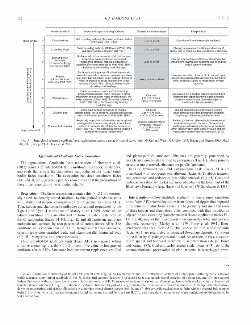
FIG. 5.—Hierarchical scheme describing fluvial architecture across a range of spatial scales (after McKee and Weir 1953; Allen 1983; Bridge and Diemer 1983; Miall1988, 1991; Bridge 1993; Hajek et al. 2010).
R
FIG. 6.—Illustration of hierarchy of fluvial architectural units (Fig. 5). A) Uninterpreted and B, C) interpreted sections of a photopan illustrating bedsets stackedwithin a channel story (minor sandbody 3; Fig. 9). Interpreted sections illustrate (B) a single bedset that records lateral accretion of a point bar, and (C) three stackedbedsets that occur within a single channel story. D) Uninterpreted and E, F) interpreted sections of a photopan illustrating channel belts stacked within a channel-beltcomplex (major sandbody 6; Fig. 12). Interpreted sections illustrate (E) part of a single channel belt that contains preserved remnants of multiple lateral-accretion,downstream-accretion, and channel-fill bedsets in a multiple thread channel system (belt 2), and (F) five vertically stacked channel belts within a channel-belt complex(belts 1, 2, 4, 5, 6). Note that surfaces bounding channel stories and channel belts in Parts B, C, E, and F are shown using the same line weight, but are differentiated bytext annotations.
152 G.J. HAMPSON ET AL. J S R
MODEST CHANGE IN FLUVIAL STYLE WITHIN REGRESSIVE CLASTIC WEDGE 153J S R
which requires sustained conditions of high water table and clastic-sediment starvation (Bohacs and Suter 1996). In the lower BlackhawkFormation, laterally extensive coal zones generally formed duringtransgression in a broad, coastline-parallel belt (Dubiel et al. 2000;Hampson et al. 2012).
ARCHITECTURAL ANALYSIS OF FLUVIAL SANDBODIES
Architectural units are identified in the studied channelized fluvialsandbodies using the geometry, extent, and crosscutting relationships oferosion surfaces, combined with the lateral and vertical arrangement offacies (F1–F4) (cf. architectural-element analysis of Miall 1985, 1988),following the rules for hierarchical ordering of surfaces established byHolbrook (2001, p. 183). We use a hierarchical scheme synthesized fromprevious work (McKee and Weir 1953; Allen 1983; Bridge and Diemer1983; Miall 1988, 1991; Bridge 1993; Hajek et al. 2010; Payenberg et al.
2011) to describe and interpret the arrangement of architectural unitswithin sandbodies, and also the stacking arrangement of sandbodies intolarger architectural patterns (Figs. 5, 6). Our focus here is on larger unitswithin the hierarchical scheme (channel stories, channel belts, channel-belt complexes as defined in Fig. 5; cf. Payenberg et al. 2011), althoughunits at intermediate scales (bedset growth increments, bedsets) and theirconstituent smaller elements (cross-bed sets and cosets) are used tointerpret channel and bar types and their behaviors. Below we describethe criteria that have been applied to interpret channel stories, channelbelts, and channel-belt complexes in the study dataset.
Both channel stories and channel belts (levels 5 and 6, respectively, ofarchitectural hierarchy in Fig. 5) occur as channelized sandbodies with abasal erosion surface that may be lined with a discontinuous mudclast lag.Their distinction is based on the degree of architectural complexity withinthe sandbodies. Each interpreted channel story has a relatively simpleinternal architecture that comprises the deposits of a single bar
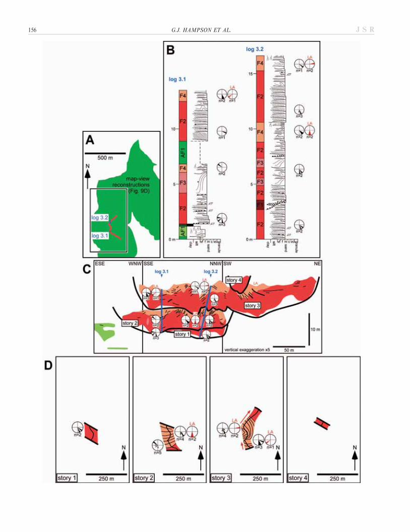
FIG. 7.—Summary of outcrop data constraining the internal architecture of major sandbody 1 within the study area (Fig. 3): A) map showing sandbody outcrop andmeasured sections; B) measured sections; C) bedding diagram constructed from interpreted cliff-face photomontages (cf. Fig. 6) tied to measured sections, showinginterpreted channel-story and channel-belt units 1–6 (cf. Fig. 5); and D) map-view reconstructions of channel-story and channel-belt units 1–6.
154 G.J. HAMPSON ET AL. J S R
macroform and adjacent channel fill (e.g., Fig. 6C). Each interpretedchannel belt has a more complex internal architecture, consisting ofmultiple, laterally stacked channel stories that cut down from the sameapproximate stratigraphic level. Thus, each channel belt contains thedeposits of multiple bar macroforms and channel fills that are laterallyamalgamated to form a multilateral body (sensu Potter 1967). Our criteriato distinguish channel stories and channel belts are most effective for well-preserved deposits of single-thread channels. By definition, multiple-thread (wandering or braided) rivers contain multiple active bars andchannels whose preserved deposits are laterally amalgamated, and will becategorized as channel belts. Poorly preserved architectural units, such asthose truncated by overlying erosion surfaces, may be difficult tocategorize due to erosion of diagnostic architectural relationships. Insuch cases, we have erred on the side of caution in interpreting a smallnumber of channel belts rather than a large number of channel storieswithin a sandbody (e.g., Fig. 6E, F); however, we recognize that channelbelts comprise multiple, laterally amalgamated channel stories that we areunable to distinguish.
A channel-belt complex (level 7 of architectural hierarchy in Fig. 5)consists of multiple, vertically stacked channel stories and channel beltsthat cut down from different stratigraphic levels to form a multistorybody (sensu Potter 1967). Complexes and their constituent stories andbelts may be confined above a deep, ‘‘master’’ erosion surface ofcomposite character (e.g., within a paleovalley). Alternatively, near themargins of a complex that lacks a ‘‘master’’ erosion surface at its base, itmay be possible to identify preserved intervals of aggradationalfloodplain deposits (facies AF1–AF3) in between the basal erosionsurfaces of individual stories and belts. The latter architecture allowsmore confident interpretation of channel-belt complexes, becausearchitectural relationships between their constituent stories and beltsare more fully preserved.
The architectures of each of the six major and three minor sandbodiesare presented in a series of bedding diagrams and map-view reconstruc-tions (Figs. 7–12), based on detailed interpretations of photomontages(e.g., Fig. 6) tied to measured sections. In each of the bedding diagrams(Figs. 7C, 8C, 9C, 10C, 11E, 12C), surfaces bounding channel stories andchannel belts (i.e., fifth- and sixth-order surfaces, Fig. 5) are shown usingthe same line weight, but are differentiated by text annotations. These
surfaces are traced out to their full interpreted extent, in order to showlarge-scale truncation, lap-out, and ordering relationships (cf. Holbrook2001). Lower-order surfaces, including macroform-accretion and macro-form-boundary surfaces (third- and fourth-order surfaces, Fig. 5) aremarked by limited lithologic and facies contrasts that are commonly notpicked out by outcrop weathering, so that these surfaces can only rarelybe traced out fully to their terminations (as indicated in Figs. 6, 7C, 8C,9C, 10C, 11E, 12C). Robust interpretations of macroform type andgeometry can therefore be made only in some parts of each channel storyor channel belt, and elsewhere analysis of intra-story and intra-beltarchitectures is more interpretive. The maps (Figs. 7D, 8D, 9D, 10D,11F, G, 12D) are reconstructed by combining four parameters: (1) thepreserved extent at outcrop of the channel story or channel belt; (2) thedistribution of facies distributions, macroform-accretion and macroform-boundary surfaces (third- and fourth-order surfaces, Fig. 5) in the upperpart of the story or belt; (3) the dip directions of macroform-accretionand macroform-boundary surfaces; and (4) paleocurrent readings fromcross-beds and current-ripple cross-lamination. The architecture of eachsandbody is described briefly below.
Architecture of Major Sandbody 1
Major sandbody 1 is exposed throughout the study area (Figs. 3, 7A).Laterally extensive erosion surfaces lined by discontinuous mudclast lags(facies F1) define the base of channel-story and channel-belt architecturalunits (cf. Fig. 5). Channel belt 1 is strongly erosionally truncated(Fig. 7C), and the preserved remnant consists principally of cross-bedded, medium-grained sandstones (facies F2). Channel belt 2 comprisescross-bedded, medium-grained sandstones (facies F2) with isolated bodiesof folded sandstone (facies F3), which grade upward into poorlypreserved, inclined, intercalated sandstones and siltstones (facies F4)(Fig. 7C) that record lateral accretion relative to local paleoflow(Fig. 7D). Channel story 3 comprises mainly inclined, intercalatedsandstones and siltstones (facies F4), which record the northeastwardadvance of a barform with flanks that built out to the north and south(i.e., obliquely downstream relative to local paleoflow; Fig. 7C, D).Channel story 4 cuts down from a similar stratigraphic level, and may becontiguous with channel story 3 (Fig. 7C). It consists of cross-bedded,medium-grained sandstones (facies F2) that pass laterally and upward
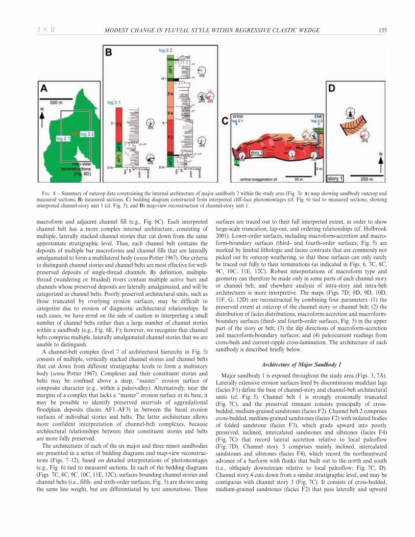
FIG. 8.—Summary of outcrop data constraining the internal architecture of major sandbody 2 within the study area (Fig. 3): A) map showing sandbody outcrop andmeasured sections; B) measured sections; C) bedding diagram constructed from interpreted cliff-face photomontages (cf. Fig. 6) tied to measured sections, showinginterpreted channel-story unit 1 (cf. Fig. 5); and D) map-view reconstruction of channel-story unit 1.
MODEST CHANGE IN FLUVIAL STYLE WITHIN REGRESSIVE CLASTIC WEDGE 155J S R
156 G.J. HAMPSON ET AL. J S R
into inclined, intercalated sandstones and siltstones (facies F4) (Fig. 7C)recording lateral accretion (Fig. 7D). The story has an asymmetric cross-sectional profile, with the steep cutbank offset by a series of growthfaults (Fig. 7C). Channel stories 5 and 6 both comprise cross-bedded,medium-grained sandstones (facies F2) that grade upward into laterallyaccreted, inclined, intercalated sandstones and siltstones (facies F4)(Fig. 7C, D). Channel belts 1, 2, and channel story 3 are verticallystacked with minor aggradation in the western part of the study area,whereas channel stories 4–6 exhibit more pronounced vertical stackingand are progressively offset laterally towards the northeast (Fig. 7C, D).The bases of channel belts 1 and 2 are amalgamated into a compositeerosion surface (Fig. 7C), whereas channel stories 3–6 pass laterally intopoorly exposed aggradational floodplain deposits (facies AF1–AF3)(Fig. 7C). Major sandbody 1 is poorly exposed on the east face of LinkCanyon, and the internal architecture of the sandbody has not beendocumented here.
Architecture of Major Sandbody 2
Major sandbody 2 pinches out to the west and east in the study area(Figs. 3, 8A), and consists of a single channel-story unit. Channel story 1comprises cross-bedded, medium-grained sandstones (facies F2) withisolated bodies of folded sandstone (facies F3), which grade upward intoinclined, intercalated sandstones and siltstones (facies F4) (Fig. 8B, C)that record lateral accretion relative to local paleoflow (Fig. 8D). Theupper part of the story in the west-southwest likely consists of anasymmetric, fine-grained body that is not exposed (Fig. 8C); this bodymay represent a fine-grained channel plug.
Architecture of Major Sandbody 3
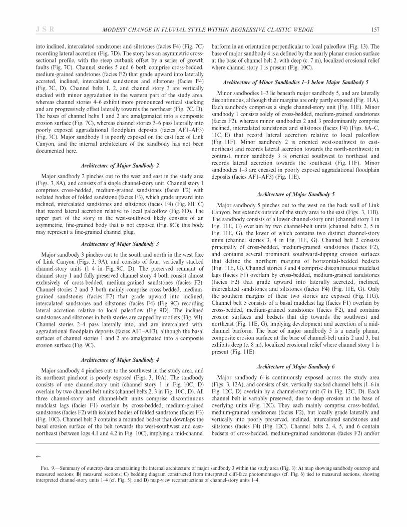
Major sandbody 3 pinches out to the south and north in the west faceof Link Canyon (Figs. 3, 9A), and consists of four, vertically stackedchannel-story units (1–4 in Fig. 9C, D). The preserved remnant ofchannel story 1 and fully preserved channel story 4 both consist almostexclusively of cross-bedded, medium-grained sandstones (facies F2).Channel stories 2 and 3 both mainly comprise cross-bedded, medium-grained sandstones (facies F2) that grade upward into inclined,intercalated sandstones and siltstones (facies F4) (Fig. 9C) recordinglateral accretion relative to local paleoflow (Fig. 9D). The inclinedsandstones and siltstones in both stories are capped by rootlets (Fig. 9B).Channel stories 2–4 pass laterally into, and are intercalated with,aggradational floodplain deposits (facies AF1–AF3), although the basalsurfaces of channel stories 1 and 2 are amalgamated into a compositeerosion surface (Fig. 9C).
Architecture of Major Sandbody 4
Major sandbody 4 pinches out to the southwest in the study area, andits northeast pinchout is poorly exposed (Figs. 3, 10A). The sandbodyconsists of one channel-story unit (channel story 1 in Fig. 10C, D)overlain by two channel-belt units (channel belts 2, 3 in Fig. 10C, D). Allthree channel-story and channel-belt units comprise discontinuousmudclast lags (facies F1) overlain by cross-bedded, medium-grainedsandstones (facies F2) with isolated bodies of folded sandstone (facies F3)(Fig. 10C). Channel belt 3 contains a mounded bedset that downlaps thebasal erosion surface of the belt towards the west-southwest and east-northeast (between logs 4.1 and 4.2 in Fig. 10C), implying a mid-channel
barform in an orientation perpendicular to local paleoflow (Fig. 13). Thebase of major sandbody 4 is a defined by the nearly planar erosion surfaceat the base of channel belt 2, with deep (c. 7 m), localized erosional reliefwhere channel story 1 is present (Fig. 10C).
Architecture of Minor Sandbodies 1–3 below Major Sandbody 5
Minor sandbodies 1–3 lie beneath major sandbody 5, and are laterallydiscontinuous, although their margins are only partly exposed (Fig. 11A).Each sandbody comprises a single channel-story unit (Fig. 11E). Minorsandbody 1 consists solely of cross-bedded, medium-grained sandstones(facies F2), whereas minor sandbodies 2 and 3 predominantly compriseinclined, intercalated sandstones and siltstones (facies F4) (Figs. 6A–C,11C, E) that record lateral accretion relative to local paleoflow(Fig. 11F). Minor sandbody 2 is oriented west-southwest to east-northeast and records lateral accretion towards the north-northwest; incontrast, minor sandbody 3 is oriented southwest to northeast andrecords lateral accretion towards the southeast (Fig. 11F). Minorsandbodies 1–3 are encased in poorly exposed aggradational floodplaindeposits (facies AF1–AF3) (Fig. 11E).
Architecture of Major Sandbody 5
Major sandbody 5 pinches out to the west on the back wall of LinkCanyon, but extends outside of the study area to the east (Figs. 3, 11B).The sandbody consists of a lower channel-story unit (channel story 1 inFig. 11E, G) overlain by two channel-belt units (channel belts 2, 5 inFig. 11E, G), the lower of which contains two distinct channel-storyunits (channel stories 3, 4 in Fig. 11E, G). Channel belt 2 consistsprincipally of cross-bedded, medium-grained sandstones (facies F2),and contains several prominent southward-dipping erosion surfacesthat define the northern margins of horizontal-bedded bedsets(Fig. 11E, G). Channel stories 3 and 4 comprise discontinuous mudclastlags (facies F1) overlain by cross-bedded, medium-grained sandstones(facies F2) that grade upward into laterally accreted, inclined,intercalated sandstones and siltstones (facies F4) (Fig. 11E, G). Onlythe southern margins of these two stories are exposed (Fig. 11G).Channel belt 5 consists of a basal mudclast lag (facies F1) overlain bycross-bedded, medium-grained sandstones (facies F2), and containserosion surfaces and bedsets that dip towards the southwest andnortheast (Fig. 11E, G), implying development and accretion of a mid-channel barform. The base of major sandbody 5 is a nearly planar,composite erosion surface at the base of channel-belt units 2 and 3, butexhibits deep (c. 8 m), localized erosional relief where channel story 1 ispresent (Fig. 11E).
Architecture of Major Sandbody 6
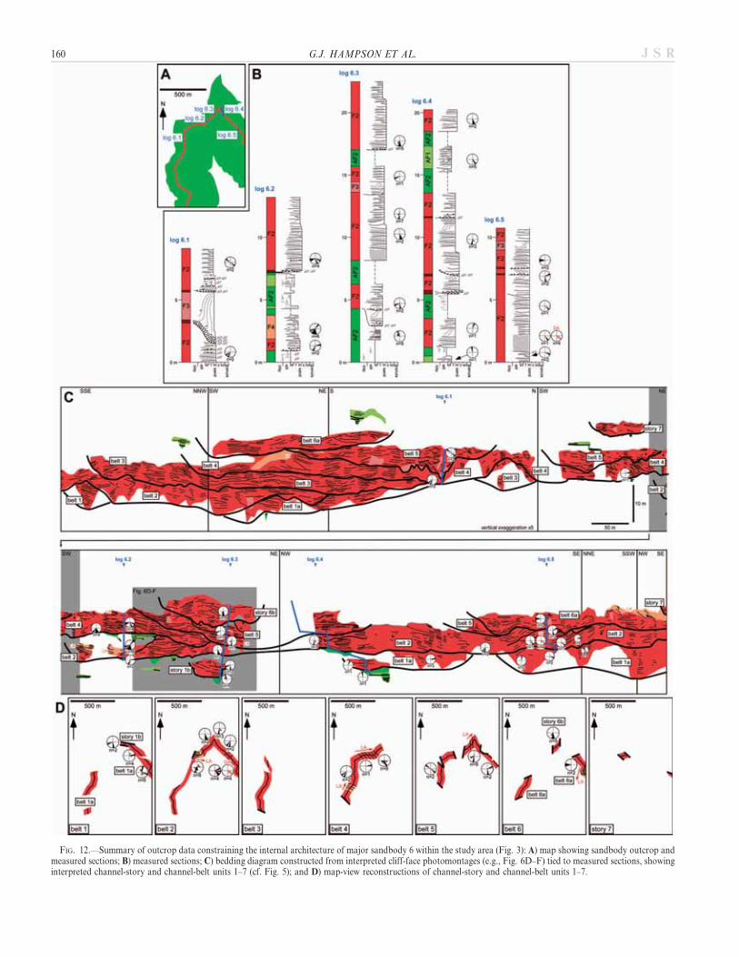
Major sandbody 6 is continuously exposed across the study area(Figs. 3, 12A), and consists of six, vertically stacked channel belts (1–6 inFig. 12C, D) overlain by a channel-story unit (7 in Fig. 12C, D). Eachchannel belt is variably preserved, due to deep erosion at the base ofoverlying units (Fig. 12C). They each mainly comprise cross-bedded,medium-grained sandstones (facies F2), but locally grade laterally andvertically into poorly preserved, inclined, intercalated sandstones andsiltstones (facies F4) (Fig. 12C). Channel belts 2, 4, 5, and 6 containbedsets of cross-bedded, medium-grained sandstones (facies F2) and/or
r
FIG. 9.—Summary of outcrop data constraining the internal architecture of major sandbody 3 within the study area (Fig. 3): A) map showing sandbody outcrop andmeasured sections; B) measured sections; C) bedding diagram constructed from interpreted cliff-face photomontages (cf. Fig. 6) tied to measured sections, showinginterpreted channel-story units 1–4 (cf. Fig. 5); and D) map-view reconstructions of channel-story units 1–4.
MODEST CHANGE IN FLUVIAL STYLE WITHIN REGRESSIVE CLASTIC WEDGE 157J S R
intercalated sandstones and siltstones (facies F4) that are generallyinclined perpendicular to paleoflow, indicating lateral accretion(Fig. 12C–D). Channel belt 2 also contains a downstream-accretedbedset of cross-bedded, medium-grained sandstones (facies F2)
(Fig. 12C–D). Channel story 3 comprises a discontinuous mudclast lag(facies F1) overlain by cross-bedded, medium-grained sandstones (faciesF2) with isolated bodies of folded sandstone (facies F3). Many of thechannel belts and stories pass laterally into, or are intercalated with,
FIG. 10.—Summary of outcrop data constraining the internal architecture of major sandbody 4 within the study area (Fig. 3): A) map showing sandbody outcrop andmeasured sections; B) measured sections; C) bedding diagram constructed from interpreted cliff-face photomontages (cf. Fig. 6) tied to measured sections, showinginterpreted channel-story and channel-belt units 1–3 (cf. Fig. 5); and D) map-view reconstructions of channel-story and channel-belt units 1–3.
158 G.J. HAMPSON ET AL. J S R
aggradational floodplain deposits (facies AF1–AF3) (Figs. 4I, 6D–F,12C), such that the base of the sandbody does not define a ‘‘master’’erosion surface composed of erosionally amalgamated channel-story andchannel-belt bases.
INTERPRETATION OF FLUVIAL SANDBODY ARCHITECTURES
The six major sandbodies described above (Figs. 7–12) have qualita-tively similar internal architectures. Each major sandbody consists of thesame facies in similar proportions, and contains architectural units of thesame style and hierarchical level (cf. Fig. 5). Architectural elements withinchannel-story units are typically incompletely preserved, but include thedeposits of laterally, obliquely, and downstream-accreted bars, and bothtabular and channelized cross-bedded-sandstone elements. Upstreamaccretion is not observed. Nearly horizontal sandstone strata that onlapchannelized erosion surfaces are interpreted to record an active ‘‘cut and
fill’’ style of channel infilling characterized by vertical accretion.Interpretation of paleochannel morphology from outcrop data is fraughtwith challenges (e.g., Bridge 1985; Ethridge 2011). Nevertheless, incombination, the various architectural elements described above suggestthat the sandbodies were deposited by river channels and bars thatexhibited components of straight, meandering, wandering, and braidedfluvial styles (sensu Rust 1978; Church 1983). We cannot discountanastomosing or anabranching channel-planform patterns, with multiplecoeval channels of the type described above separated by vegetated,semipermanent islands (cf. Knighton and Nanson 1993), particularly atareal scales larger than that of the study area (Fig. 3B). We interpret thatstories with a simple ‘‘cut-and-fill’’ architecture, and stories and beltscontaining pervasive lateral-to-oblique accretion with a consistentdirection were deposited by a single-thread, straight-to-meanderingchannel. In contrast, belts containing downstream-accreted elementsand mid-channel barforms are interpreted to have been deposited by
FIG. 11.—Summary of outcrop data constraining the internal architecture of minor sandbodies 1–3 and major sandbody 5 within the study area (Fig. 3): mapsshowing outcrop and measured sections of A) minor sandbodies 1–3 and B) major sandbody 5; measured sections through C) minor sandbodies 1–3 and D) majorsandbody 5; E) bedding diagram constructed from interpreted cliff-face photomontages (e.g., Fig. 6A–C) tied to measured sections, showing interpreted channel-storyand channel-belt units (cf. Fig. 5); and map-view reconstructions of F) minor sandbodies 1–3, each consisting of a channel-story unit, and G) map-view reconstructions ofchannel-story and channel-belt units 1–5 in major sandbody 5.
MODEST CHANGE IN FLUVIAL STYLE WITHIN REGRESSIVE CLASTIC WEDGE 159J S R
FIG. 12.—Summary of outcrop data constraining the internal architecture of major sandbody 6 within the study area (Fig. 3): A) map showing sandbody outcrop andmeasured sections; B) measured sections; C) bedding diagram constructed from interpreted cliff-face photomontages (e.g., Fig. 6D–F) tied to measured sections, showinginterpreted channel-story and channel-belt units 1–7 (cf. Fig. 5); and D) map-view reconstructions of channel-story and channel-belt units 1–7.
160 G.J. HAMPSON ET AL. J S R
multiple-thread, wandering-to-braided channels. Sandbodies in theuppermost Blackhawk Formation and lower Castlegate Sandstone havepreviously been interpreted as the deposits of multiple-thread, braidedchannels on the basis of architectural analysis and barform reconstruc-tions (Miall 1993, 1994; Adams and Bhattacharya 2005; McLaurin andSteel 2007). The three minor sandbodies each comprise a single story, twoof which are dominated by lateral accretion with a consistent direction(stories 2, 3) and one by tabular cross-bedded-sandstone elements (story1) (Fig. 12). These three sandbodies are interpreted to have beendeposited by single-thread channels. Below we assess quantitative aspectsof the sandbodies and the architectural units that comprise them, andinterpret the paleohydraulic conditions under which they were deposited.
Variation in Dimensions of Sandbodies and Their Architectural Components
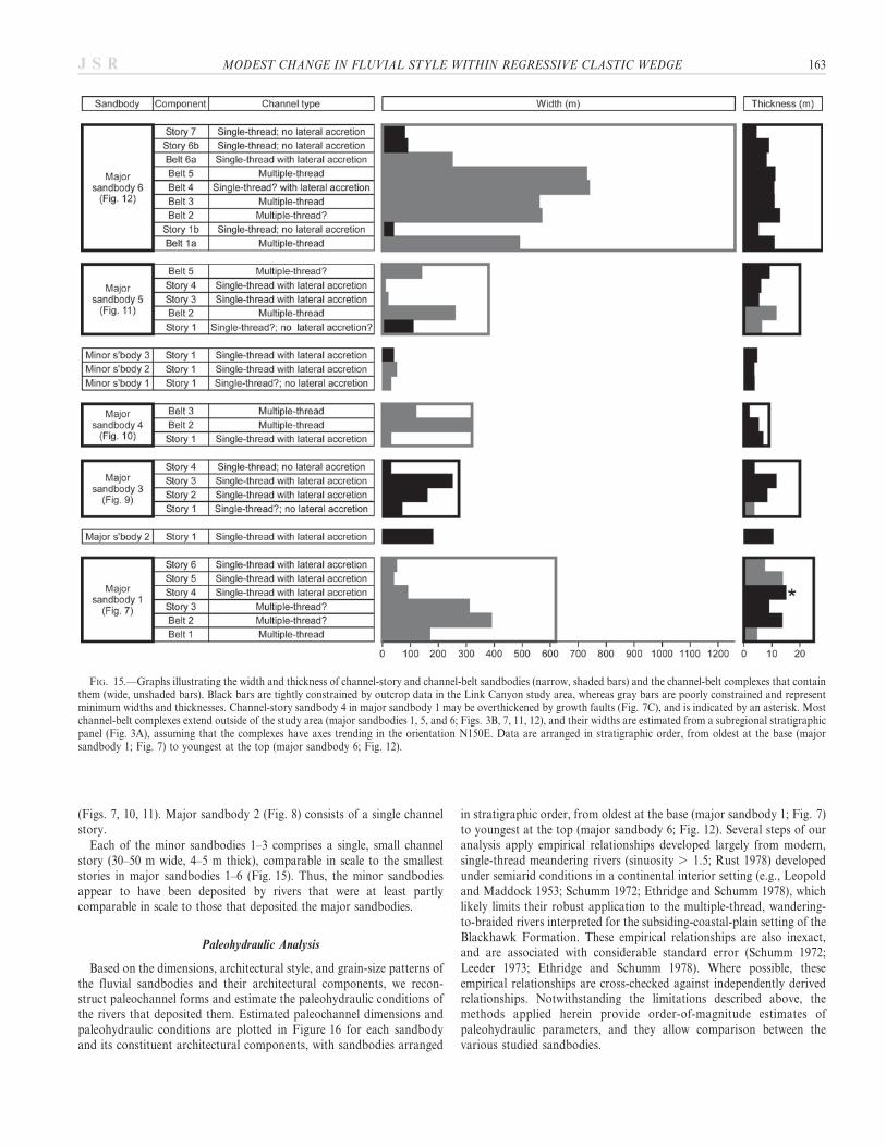
Thicknesses of the major and minor sandbodies, and of theirarchitectural components, are taken from measured sections (Figs. 7B,8B, 9B, 10B, 11C, 11D, 12B) and bedding diagrams (Figs. 7C, 8C, 9C,10C, 11E, 12C). Sandbody widths are taken from map-view reconstruc-tions (Figs. 7D, 8D, 9D, 10D, 11F, 11G, 12D), and are measuredperpendicular to the interpreted trend of one or both sandbody margins,where the margins are constrained by the available data (i.e., truesandbody width is measured). Where sandbody margins are poorlyconstrained, their apparent widths are measured perpendicular to themean paleocurrent direction within the sandbody. Major sandbodies 1, 5,and 6 extend outside of the Link Canyon study area (Figs. 3B, 7, 11, 12);their widths are estimated from a subregional stratigraphic panel(Fig. 3A), assuming that the complexes have axes trending in theorientation N150E. This orientation is reasonably well constrained bythe mapped distribution of the three sandbodies in cliff faces adjacent tothe Link Canyon study area, and it is also broadly consistent with theorientation and paleocurrent data of at least some architecturalcomponents in each sandbody (Figs. 7D, 11G, 12D) and with the
orientation of major sandbodies 2, 3, and 4 (Figs. 8D, 9D, 10D). Allsandbodies are assumed to be linear in map view over the short along-axisdistances used to estimate their widths (100–1000 m for majorsandbodies, , 50 m for minor sandbodies). The estimated dimensionsof the sandbodies and their architectural components are accurate toapproximately 6 10%.
Channel-story, channel-belt, and channel-belt-complex sandbodieshave distinctly different ranges of width and thickness, with somedegree of overlap (Fig. 14). Channel-story sandbodies are generallynarrow (mean 6 standard deviation of 90 6 80 m) and thin (7 6 4 m)(Fig. 14A). Channel-belt sandbodies are wider (400 6 220 m) but ofsimilar thickness (9 6 4 m) (Fig. 14B). Channel-belt-complex sandbo-dies are of similar width to channel-belt sandbodies (400 6 160 m), butare thicker than the latter (20 6 7 m) (Fig. 14C). These relative rangesof sandbody dimensions are unsurprising, since they reflect thediagnostic criteria and interpreted origin of channel-story, channel-belt,and channel-belt-complex sandbodies: channel stories are amalgamatedlaterally to form multilateral channel belts, and channel belts are stackedvertically to form multistory channel-belt complexes (Fig. 5). Using datafrom nearby localities (Salina Canyon and Castle Gate localities; Figs. 1,2), similar thicknesses have been documented for channel-storysandbodies in the lower Castlegate Sandstone (1–8 m, Miall 1993; 2–12 m, McLaurin and Steel 2007), channel-belt sandbodies in theuppermost Blackhawk Formation (5–8 m, Adams and Bhattacharya2005) and lower Castlegate Sandstone (4–7 m, Adams and Bhattacharya2005; 2–16 m, McLaurin and Steel 2007, Hajek and Heller 2012), andchannel-belt-complex sandbodies in the lower Castlegate Sandstone (17–40 m, McLaurin and Steel 2007). The widths of channel-story, channel-belt, and channel-belt-complex sandbodies are poorly constrained inthese previous studies (Miall 1993; Adams and Bhattacharya 2005;McLaurin and Steel 2007), principally because fully preserved examplesof these architectural units are sparse or absent in the lower CastlegateSandstone.
FIG. 13.—A) Uninterpreted and B) interpreted sections of a photopan illustrating two channel belts stacked within a channel-belt complex (major sandbody 4;Fig. 10). The upper channel belt (belt 2) contains a bedset that records vertical and lateral accretion in opposite directions of a mounded, mid-channel bar within amultiple-thread channel system. Note that surfaces bounding channel stories and channel belts in Parts B and C are shown using the same line weight.
MODEST CHANGE IN FLUVIAL STYLE WITHIN REGRESSIVE CLASTIC WEDGE 161J S R
Stratigraphic variations in the dimensions of the fluvial sandbodies andtheir constituent architectural components have also been analyzed(Fig. 15). There are no consistent stratigraphic trends in either width orthickness of the channel-belt-complex sandbodies (major sandbodies 1, 3,4, 5, 6), although the youngest complex (major sandbody 6) is markedlywider (1260 m) than the four older complexes (270–620 m) (Fig. 15). Thisincreased width is partly a reflection of wider channel belts in majorsandbody 6 (250–740 m) relative to those in older complexes (120–390 min major sandbodies 1, 3, 4, 5) (Fig. 15), and partly due to greater lateraloffsets between the channel stories and belts stacked within majorsandbody 6 (Fig. 12C, D).
Channel-story and channel-belt dimensions and stacking patternswithin each major sandbody are highly variable (Fig. 15), such that: (1)there are no systematic trends shared by the sandbodies, and (2)variability within each sandbody is comparable in magnitude to thevariability between sandbodies. Composite erosion surfaces at the basesof major sandbodies 1, 4, and 5 (Figs. 7, 10, 11) can be interpreted asunconformities at the base of stratigraphic valleys (sensu Strong andPaola 2008). However, the internal architecture of the sandbodies lacksthe two diagnostic features of incised-valley fills formed by relative sea-level change in coastal-plain settings (e.g., Zaitlin et al. 1994): (1) anupward increase in preserved channel-story and channel-belt thickness,reflecting increasing accommodation during valley filling, and (2) an
upward change in fluvial style that reflects progressively decreasingchannel slope (e.g., low- to high-sinuosity) or increasing marineinfluence during transgressive backfilling of the valley. The erosionalbases of these major sandbodies cannot also be mapped or correlated todefine a regional network of paleovalleys developed at an incisionalsurface, as for coastal incised-valley fills (e.g., in the lowermostBlackhawk Formation north of the Link Canyon study area; figs. 12C,D, 13 in Hampson et al. 2012). Instead, stratigraphic valleys may havebeen cut and filled in response to local changes in the balance ofsediment flux and transport capacity, within the limits set by base-levelbuffers driven by upstream controls (Holbrook et al. 2006). Architec-tures within such valley fills may appear disorganized, and principallyreflect a combination of high-frequency climatic controls and autogenicresponses related to internal and geomorphic thresholds (e.g., Westcott1993; Holbrook 2001; Holbrook et al. 2006; Gibling et al. 2011). Majorsandbodies 3 and 6 (Figs. 9, 12) lack composite, valley-form erosionsurfaces at their bases, but instead comprise vertically stacked channelstories and channel belts whose margins are offset laterally andseparated vertically by floodplain deposits. These sandbodies do notrepresent stratigraphic valleys, but the stacking of their constituentchannel stories and channel belts is attributed to a combination ofavulsion and local variations in sediment flux and transport capacity, asin the candidate stratigraphic valleys of major sandbodies 1, 4, and 5
FIG. 14.—Graphs illustrating the width and thickness of A) channel-story, B) channel-belt, and C) channel-belt-complex sandbodies (Figs. 5–12). Black points aretightly constrained by outcrop data in the Link Canyon study area, whereas gray points are poorly constrained due to incomplete exposure and represent minimumwidths and thicknesses. Channel-story sandbody 4 in major sandbody 1 may be overthickened by growth faults (Fig. 7C), and is indicated by an asterisk in Part A. Best-fit linear-regression lines with coefficients of determination (R2 values) are shown. Correlations are strong for R2 . 0.8, moderate for 0.8 . R2 . 0.5, and weak for0.5 . R2. In Part A, best-fit regression lines are shown for tightly and poorly constrained data in black and gray, respectively.
162 G.J. HAMPSON ET AL. J S R
(Figs. 7, 10, 11). Major sandbody 2 (Fig. 8) consists of a single channelstory.
Each of the minor sandbodies 1–3 comprises a single, small channelstory (30–50 m wide, 4–5 m thick), comparable in scale to the smalleststories in major sandbodies 1–6 (Fig. 15). Thus, the minor sandbodiesappear to have been deposited by rivers that were at least partlycomparable in scale to those that deposited the major sandbodies.
Paleohydraulic Analysis
Based on the dimensions, architectural style, and grain-size patterns ofthe fluvial sandbodies and their architectural components, we recon-struct paleochannel forms and estimate the paleohydraulic conditions ofthe rivers that deposited them. Estimated paleochannel dimensions andpaleohydraulic conditions are plotted in Figure 16 for each sandbodyand its constituent architectural components, with sandbodies arranged
in stratigraphic order, from oldest at the base (major sandbody 1; Fig. 7)to youngest at the top (major sandbody 6; Fig. 12). Several steps of ouranalysis apply empirical relationships developed largely from modern,single-thread meandering rivers (sinuosity . 1.5; Rust 1978) developedunder semiarid conditions in a continental interior setting (e.g., Leopoldand Maddock 1953; Schumm 1972; Ethridge and Schumm 1978), whichlikely limits their robust application to the multiple-thread, wandering-to-braided rivers interpreted for the subsiding-coastal-plain setting of theBlackhawk Formation. These empirical relationships are also inexact,and are associated with considerable standard error (Schumm 1972;Leeder 1973; Ethridge and Schumm 1978). Where possible, theseempirical relationships are cross-checked against independently derivedrelationships. Notwithstanding the limitations described above, themethods applied herein provide order-of-magnitude estimates ofpaleohydraulic parameters, and they allow comparison between thevarious studied sandbodies.
FIG. 15.—Graphs illustrating the width and thickness of channel-story and channel-belt sandbodies (narrow, shaded bars) and the channel-belt complexes that containthem (wide, unshaded bars). Black bars are tightly constrained by outcrop data in the Link Canyon study area, whereas gray bars are poorly constrained and representminimum widths and thicknesses. Channel-story sandbody 4 in major sandbody 1 may be overthickened by growth faults (Fig. 7C), and is indicated by an asterisk. Mostchannel-belt complexes extend outside of the study area (major sandbodies 1, 5, and 6; Figs. 3B, 7, 11, 12), and their widths are estimated from a subregional stratigraphicpanel (Fig. 3A), assuming that the complexes have axes trending in the orientation N150E. Data are arranged in stratigraphic order, from oldest at the base (majorsandbody 1; Fig. 7) to youngest at the top (major sandbody 6; Fig. 12).
MODEST CHANGE IN FLUVIAL STYLE WITHIN REGRESSIVE CLASTIC WEDGE 163J S R
Methods.—Bankfull flow depth (D) is estimated from the measuredthickness of a channel story or belt (h). Allowing for reduction ofchannel-story or channel-belt sandbody thickness by 10% duringcompaction,
D~h=0:9 ð1Þ
Ethridge and Schumm (1978) developed a different relationship formeandering channels, based on laboratory experiments in which bankfullflow depth was observed to be smaller than point-bar thickness (Khan1971). Here, we use the thickness of channel-story and channel-beltsandbodies (h) as a proxy for compacted point-bar thickness, forsandbodies in which point bars are incompletely preserved:
D~0:585 h=0:9ð Þ ð2Þ
In our analysis, we use Equation 1 to estimate bankfull flow depth inchannel-story sandbodies lacking large-scale inclined surfaces (i.e., simple‘‘cut-and-fill’’ sandbodies interpreted to record single-thread channels),and Equation 2 to estimate bankfull flow depth in channel-story and
channel-belt sandbodies containing inclined surfaces that indicate lateral,oblique, or downstream bar accretion.
For channel-story and channel-belt sandbodies with a simple ‘‘cut-and-fill’’ architecture (i.e., lacking evidence of lateral, oblique, or downstreambar accretion), bankfull channel width (W) is taken from outcropmeasurements of apparent story width that are then corrected foroutcrop-face orientation, so that the reported widths are estimatedperpendicular to either story margins (e.g., using maps in Figs. 7D, 8D,9D, 10D, 11F, 11G, 12D) or to mean paleocurrent direction in the channelfill. The observed widths of other channel-story and channel-beltsandbodies record a combination of bankfull channel width and baraccretion. For channel-story and channel-belt sandbodies that containlateral-accretion bedsets and are interpreted to have been deposited bysingle-thread channels, bankfull channel width is estimated frommeasuredsandbody thickness (h) and the dip angle of lateral-accretion surfaces (b)using the relationship proposed by Allen (1965) for meandering channels:
W~1:5 h=tan bð Þ ð3Þ
The apparent dip angle of lateral-accretion surfaces measured in anoutcrop face is corrected so that it is estimated perpendicular to mean
FIG. 16.—Graphs illustrating estimated values of paleohydraulic parameters for channel-story and channel-belt sandbodies. Black bars represent values that are tightlyconstrained by outcrop data in the Link Canyon study area, whereas gray bars represent poorly constrained values. The width of the bars represents estimated uncertaintydue to poor outcrop-data constraints, and due to standard errors reported for empirical relationships (Schumm 1972; Leeder 1973; Ethridge and Schumm 1978;Bhattacharya and Tye 2004). The upper limits of estimates of bankfull channel width are taken from sandbody width (Fig. 15) (shown as thin dashed lines where applied,for major sandbodies 1, 4, 5, and 6). Channel story 4 in major sandbody 1 may be overthickened by growth faults (Fig. 7C), resulting in overestimation of bankfull depth,bankfull width, and peak discharge, and underestimation of channel slope; these values are indicated by an asterisks. The shaded field in the sinuosity column representsstraight channels (1 . sinuosity . 1.5), while the unshaded field represents meandering channels (sinuosity . 1.5). Data are arranged in stratigraphic order, fromoldest at the base (major sandbody 1; Fig. 7) to youngest at the top (major sandbody 6; Fig. 12).
164 G.J. HAMPSON ET AL. J S R
paleocurrent direction in the lateral-accretion bedset that contains them.For channel-belt sandbodies that contain downstream-accretion bedsetsor mid-channel bars and are interpreted to have been deposited bymultiple-thread channels, bankfull channel width is estimated from anempirical relationship with bankfull flow depth derived for modernbraided rivers in the mid-continent USA (Leopold and Maddock 1953):
W~42 D1:11 ð4Þ
Sinuosity (P) is estimated for channel-story and channel-belt sandbo-dies that contain lateral-accretion bedsets and are interpreted to havebeen deposited by single-thread channels, using the empirical relationshipderived by Schumm (1972) for modern meandering rivers in the mid-continent USA:
P~3:5 W=Dð Þ{0:27 ð5Þ
In the same sandbodies, the ratio of observed lateral-accretion bedsetwidth (i.e., extent of lateral point-bar accretion perpendicular to accretion-surface strike, using maps in Figs. 7D, 8D, 9D, 10D, 11F, 11G, 12D) tolateral-accretion surface width (i.e., width of accretionary channel bank)reflects a combination of sinuosity, meander wavelength, and downstreammigration of the meander (e.g., Willis and Tang 2010). The quantity ofmeasured paleocurrent data is insufficient to estimate sinuosity usingstatistical methods (e.g., Langbein and Leopold 1966; Le Roux 1992).
Channel slope (S) is estimated via two empirical relationships. The firstrelationship is derived from observed bankfull channel widths and depthsfor modern rivers in the mid-continent USA (Schumm 1972):
S~30 W=Dð Þ0:95.W 0:98
n oð6Þ
The second relationship was proposed by Lynds (2005) for sand-bedrivers, following the form of a relationship for gravel-bed rivers given inPaola and Mohrig (1996):
S~ T d50bedð Þ=D ð7Þ
where T is the product of an empirically derived coefficient (bankfullnondimensional shear stress) and sediment density, and is approxi-mately equal to 2.7, and d50bed is the median grain size of the bedload,taken as 0.25 mm (fine-to-medium sand). The first relationship(Equation 6) gives slope estimates that are generally 2–3 times steeperthan the second relationship (Equation 7). However, the latter estimatesare based on the critical shear stress of transport for the d50bed grain size,which gives a minimum value of the slope required to transport bedloadmaterial of median grain size, and are accurate to within a factor of 2(Paola and Mohrig 1996). Our estimates of channel slope thus lieapproximately within the margin of error inherent to the two independenttechniques used to derive them. It should be noted that in Figure 16, slopeis plotted in degrees rather than the original units (e.g., feet per mile inSchumm 1972).
Peak discharge (Qp) is estimated using the method of Bhattacharya andTye (2004), which multiplies bankfull channel cross-sectional area againstpeak flow velocity (Up):
Qp~ 0:65 W Dð ÞUp ð8Þ
Peak flow velocity is derived using the bedform-phase diagrams ofRubin and McCulloch (1980), and is estimated from three parameters:flow depth, median bedload grain size, and dominant bedform type. Flowdepth is calculated using a combination of the experimental data of
LeClair and Bridge (2001), which indicate that mean dune height isapproximately 2.9 times mean cross-set thickness (0.2–0.3 m in thestudied sandbodies), and the empirical relationship of Yalin (1964) thatflow depth typically approximates 6–10 times mean dune height; thusflow depth is estimated at 3.5–8.7 m. Allen’s (1970) empirical relationshipbetween flow depth, D, and mean dune height, hm, (Equation 9) givescomparable values of estimated flow depth (7.3–10.3 m):
D~11:6 hm0:84 ð9Þ
Using these estimates of flow depth, combined with the observed mediangrain size of the bedload (fine-to-medium sand) and dominant bedformtype (3D dune, recorded by trough cross-bedding), peak flow velocity isestimated to have been 0.6–1.3 m s21. This range of values is used toestimate peak discharge (Fig. 16). Estimates of peak discharge (Equation8) are comparable (within 6 50%) with those of mean annual flooddischarge (Qma) estimated using the empirical relationship of Schumm(1972) for modern rivers in the mid-continent USA (Equation 10)
Qma~16 W 1:56.
W=Dð Þ0:66)n o
ð10Þ
Estimates of peak discharge (Equation 8) are 1–10 times greater thanestimates of mean annual discharge (Qm) using the empirical relationship ofSchumm (1972) for modern rivers in the mid-continent USA (Equation 10):
Qm~W 2:43.
18 W=Dð Þ1:13� �n o
ð11Þ
Each of the major fluvial sandbodies characterized within the LinkCanyon study area exhibits a similar range of interpreted paleohydraulicparameters, although this range is large and associated with significantuncertainty (Fig. 16). Four key results are highlighted below.
Bankfull Channel Dimensions.—Estimated bankfull widths and depthsof various channel types are summarized below. Single-thread channelspreserved as simple ‘‘cut-and-fill’’ bedsets (n 5 7; denoted as ‘‘single-thread, no lateral accretion’’ in Fig. 16) have estimated bankfull widths of30–110 m (mean of 60 m) and bankfull depths of 4.0–9.9 m (mean of5.7 m). Single-thread channels preserved adjacent to lateral-, oblique-,and downstream-accretion bedsets (n 5 13; denoted as ‘‘single-thread,no lateral accretion’’ in Fig. 16) have estimated bankfull widths of 20–320 m (mean of 130 m) and bankfull depths of 2.3–9.8 m (mean of 5.6 m).Multiple-thread channels (n 5 11; denoted as ‘‘multiple-thread’’ inFig. 16), have estimated bankfull widths of 80–910 m (mean of 540 m)and bankfull depths of 2.1–14.2 m (mean of 8.8 m). The estimates ofbankfull flow depth quoted above, which are derived from observedsandbody thicknesses (Equations 1 and 2; Ethridge and Schumm 1978),are consistent with values of 3.5–10.3 m derived from observations ofmean cross-set thickness and inferred dune height (e.g., Equation 9; afterYalin 1964; Allen 1970; LeClair and Bridge 2001).
The occurrence of both single-thread and multiple-thread channeldeposits within the same channel-belt complexes (e.g., major sandbodies1, 4, 5, and 6; Figs. 15, 16) implies that both types of channel coexisted onthe Blackhawk alluvial-to-coastal plain. Comparison of the estimatedbankfull channel dimensions indicates that single-thread channels had arelatively small range of bankfull widths and depths, whereas multiple-thread channels were wider and deeper. There is relatively littlestratigraphic variation in inferred bankfull channel dimensions, althoughthe estimated bankfull width of multiple-thread channel belts generallyincreases upward within the Blackhawk Formation stratigraphy, from110–340 m (belts 1–2 and story 3 in major sandbody 1; belts 2–3 in majorsandbody 4) to 80–910 m (belts 2 and 5 in major sandbody 5; belts 1a, 2,3, and 5 in major sandbody 6) (Fig. 16). This trend implies that multiple-
MODEST CHANGE IN FLUVIAL STYLE WITHIN REGRESSIVE CLASTIC WEDGE 165J S R
thread channel belts became wider with increasing distance from thecoeval shoreline (Fig. 2); they likely defined downstream-branchingnetworks of downstream-narrowing, trunk distributary channels on adelta plain (Marley et al. 1979; Flores et al. 1984; Rittersbacher et al. inpress).
Channel Sinuosity.—Single-thread channels preserved adjacent tolateral-, oblique-, and downstream-accretion bedsets in major fluvialsandbodies (n 5 14: belt 2 and stories 3–6 in major sandbody 1; story 1in major sandbody 2; stories 2–3 in major sandbody 3; story 1 in majorsandbody 4; stories 3–4 and belt 5 in major sandbody 5; and belts 4 and6a in major sandbody 6; Fig. 16) have low-to-moderate estimatedsinuosities (1.1–1.9, mean of 1.5). Single-thread channels preservedadjacent to lateral-accretion bedsets in isolated, heterolithic channelstories (n 5 2; minor sandbodies 2–3; Fig. 16) have moderate estimatedsinuosities (1.6–2.1). There is only a weak correspondence betweenestimated channel sinuosity and the ratio between lateral-accretion-setwidth and lateral-accretion-surface width (Fig. 16), which likely reflectsthe influence of meander wavelength and downstream meander migrationon this latter ratio, in addition to sinuosity (e.g., Willis and Tang 2010).These results suggest that single-thread channels were straight tomoderately sinuous in planform, despite the observation that lateral-accretion bedsets are prominent architectural components of the Black-hawk Formation sandbodies.
Channel Slope.—Best estimates of channel slope are uniformly low(, 0.04u), although there is a large standard error associated with thesevalues (e.g., wide bars in column showing channel-slope estimates, withvalues including standard errors reaching 0.2u; Fig. 16). Estimated valuesof channel slope show no trend with stratigraphic position (Fig. 16), andare comparable to modern coastal-plain and delta-plain gradients.Estimated values of channel slope are thus consistent with subtle marineinfluence in a coastal-plain setting (e.g., Teredolites-bored logs and tidallymodulated? carbonaceous drapes along cross-bed foresets, Fig. 4C, E) atmost stratigraphic levels (major sandbodies 1–5).
Peak Discharge.—Estimates of peak discharge are derived in turn fromestimates of peak flow velocity, bankfull channel width, and bankfullchannel depth (Equation 8; Bhattacharya and Tye 2004). Similarly,estimates of mean annual discharge and mean annual flood discharge arederived from estimates of bankfull channel width and depth (Equations10 and 11; Schumm 1972). Our estimated discharge values thus mimic ourestimates of bankfull channel dimensions, although uncertainties anderrors are multiplied (e.g., wide bars in column showing peak dischargeestimates; Fig. 16). Single-thread channels (n 5 20) generally have bestestimates of peak discharges (24–2200 m3s21; mean of 420 m3s21) that areabout one order of magnitude lower than those for multiple-threadchannels (n 5 11) (90–11000 m3s21; mean of 3200 m3s21). Best estimatesof peak discharges for multiple-thread channels increase up-stratigraphy,from 90–1600 m3s21 (belts 1–2 and story 3 in major sandbody 1; belts 2–3in major sandbody 4) to 180–11000 m3s21 (belts 2 and 5 in majorsandbody 5; belts 1a, 2, 3, and 5 in major sandbody 6) (Fig. 16),consistent with the development on a delta plain of wide trunkdistributary channel belts (e.g., in major sandbodies 5–6) that brancheddownstream into several narrower channel belts (e.g., in majorsandbodies 1–4) with the same overall discharge capacity (Marley et al.1979; Flores et al. 1984; Rittersbacher et al. in press).
Controls on Fluvial Style and Stratigraphic Architecture
The six major fluvial sandbodies documented in this paper occur atdifferent stratigraphic levels of the Blackhawk Formation in the LinkCanyon study area (Fig. 3). Most of these major sandbodies are channel-
belt complexes. They all consist of the same types of architecturalcomponents (Figs. 7–12), which have similar dimensions (Figs. 14, 15),and were deposited by three paleochannel types that varied little betweensandbodies: (1) single-thread ‘‘cut-and-fill’’ channels that lack lateralaccretion and were filled by vertical accretion; (2) single-thread, laterallyaccreting channels of low-to-moderate estimated sinuosity (1.1–2.1); and(3) multiple-thread, wandering-to-braided channels (Fig. 15). All threechannel types are present within most of the major sandbodies, implyingthat they were developed penecontemporaneously on a low-gradient(, 0.04u) coastal plain that was subject to some marine influence.Multiple-thread channels reconstructed in the two upper major sandbo-dies (belts 2 and 5 in major sandbody 5; belts 1a, 2, 3, and 5 in majorsandbody 6; Fig. 16) are estimated to have had higher paleodischargesthan those in the underlying sandbodies (belts 1–2 and story 3 in majorsandbody 1; belts 2–3 in major sandbody 4; Fig. 16), in part due to thewider paleochannels reconstructed in major sandbody 6 (Fig. 15). If thesevariations in estimated paleodischarge are attributed to channel positionrelative to the coeval paleoshoreline, then they imply that multiple-threadchannels of high paleodischarge (e.g., represented by sandbodies 5–6,located c. 90–100 m from approximately coeval shoreline #10 in Figs. 1,2) branched downstream to supply several multiple-thread channels oflower paleodischarge (e.g., represented by sandbodies 1–4, located c. 40–60 m from approximately coeval shorelines #3–7 in Figs. 1, 2). Thus,paleohydraulic discharge estimates imply that the major sandbodies mayrepresent delta-plain distributary networks of downstream-narrowingchannels, although his interpretation cannot yet be supported byindependent evidence. However, the most striking feature of the sixmajor sandbodies is their similarity in facies character, internalarchitectures, and interpreted paleochannel dimensions (Figs. 7–12, 16).Paleohydraulic conditions varied within a relatively small and uniformrange during deposition of the six major sandbodies to result in thismodest variation in fluvial style.
There are no systematic trends in the type or preservation of successivechannel stories and belts within each of the channel-belt complexes, suchthat the internal architectures of the sandbodies do not result fromsystematic, short-term changes in accommodation such as those thatcharacterize incised-valley fills formed by relative sea-level change incoastal-plain settings (e.g., Zaitlin et al. 1994). Major sandbodies 1, 4, and5 have composite, valley-form erosion surfaces at their bases (Figs. 7, 10,11), but their internal architectures appear to reflect local changes in thebalance of sediment flux and transport capacity due to upstream controls,such as high-frequency climatic variations, and autogenic responses (e.g.,Westcott 1993; Holbrook 2001; Holbrook et al. 2006; Gibling et al. 2011).Major sandbodies 2, 3, and 6 do not consist of vertically stacked channelstories and channel belts that are confined within composite, valley-formerosion surfaces (Figs. 8, 9, 12). Instead, the stacking of channel storiesand channel belts within major sandbodies 3 and 6 is interpreted to reflectlocalized, autogenic behavior (e.g., avulsion). Major sandbody 2 consistsof a single channel story. The similarity in stacking of architectural elementsin the major fluvial sandbodies, whether confined to candidate valleys ornot, implies that the same, localized autogenic processes operated under arelatively wide range of conditions (Fig. 2): (1) variable proximity to thecoeval shoreline, from c. 40 km (major sandbody 1) to c. 100 km (majorsandbody 6), based on regional mapping of shoreline positions at outcrop(Figs. 1, 2) (e.g., Kamola and Huntoon 1995; Taylor and Lovell 1995;Hampson 2010; Hampson et al. 2011); (2) variable sediment accumulationrate, which approximates tectonic subsidence rate, from c. 80–700 m/Myr,based on regional outcrop and subsurface mapping of stratigraphic surfacestied to dated ammonite biozones (Hampson 2010); (3) broadly uniformdistance (c. 80 km) from the highlands of the CanyonRange Culmination inthe Sevier fold-and-thrust belt (Fig. 1), whichwas the likely sediment source(DeCelles and Coogan 2006); and (4) seasonal, warm temperate-to-subtropical climatic conditions, as implied by coal-seam flora (Parker
166 G.J. HAMPSON ET AL. J S R
1976). Local, autogenic behavior has been interpreted as the principalcontrol on fluvial architecture at comparable scales in the CastlegateSandstone, which overlies the Blackhawk Formation (McLaurin and Steel2007; Hajek and Heller 2012).
The modest change in fluvial style between the major sandbodies andthe dominance of upstream controls and autogenic patterns in theirinternal stratigraphic architecture do not conform to the predictions ofsequence stratigraphic models of alluvial-to-coastal-plain successions(Wright and Marriott 1993; Shanley and McCabe 1994; Richards 1996),but are instead consistent with interpreted autogenic patterns in large-scale stratigraphic architecture of the Blackhawk Formation over theWasatch Plateau outcrop belt (Fig. 1). At this large scale, the BlackhawkFormation exhibits subtle trends of increasing size, abundance, andinterconnectedness of major fluvial sandbodies from its base to its top (cf.Fig. 3A; Hampson et al. 2012). While these overall trends are interpretedto reflect progressively decreasing tectonic subsidence, at least in theupper Blackhawk Formation and overlying Castlegate Sandstone (Adamsand Bhattacharya 2005; Hampson et al. 2012), they are superimposed onan apparently random distribution of sandbodies which exhibits localizedclustering that is independent of stratigraphic and paleogeographicposition. This clustering pattern is tentatively attributed to large-scaleavulsion (cf. Mackey and Bridge 1995; Hajek et al. 2010; Wang et al.2011). However, it contrasts with the occurrence of relatively well-organized stratigraphic cycles bounded by major, regionally extensivecoal zones in the lowermost Blackhawk Formation, which was depositedon the lower coastal plain up to 50 km from the coeval shoreline(Hampson et al. 2012). Thus autogenic behavior appears to have stronglyinfluenced fluvial stratigraphic architecture at a range of scales in alluvial-to-upper-coastal-plain strata in the Blackhawk Formation. The modestvariation in fluvial style between the major sandbodies documented inLink Canyon indicates that fluvial style in the Blackhawk Formationbears little relationship to stratigraphic organization and architecturepredicted from sequence stratigraphic models for coastal-plain settingsinfluenced by relative sea-level change. In particular, there is no overallchange from single-story, single-thread (e.g., meandering) channelsandbodies to amalgamated, multiple-thread (e.g., braided) channelsandbodies from base to top of the Blackhawk Formation, despite atransition from aggradation to pronounced progradation of coevalshallow-marine deposits that are assigned to a highstand systems tract(e.g., Howell and Flint 2003; Hampson 2010 and references therein).These results support the findings of Adams and Bhattacharya (2005),who documented no change in fluvial style across an interpreted sequenceboundary at the overlying Blackhawk-Formation-to-Castlegate-Sand-stone transition.
CONCLUSIONS
The Link Canyon study area exposes six major sandbodies developedat different stratigraphic levels of the Blackhawk Formation. The fluvialsandbodies consist of four facies: (F1) mudclast conglomerate (, 5% ofeach sandbody); (F2) thick, channelized, cross-bedded, medium-grainedsandstone (70–95%); (F3) folded sandstone (, 5% to 20%); and (F4)inclined sandstone and intercalated siltstones (, 5% to 20%). Fine-grained aggradational floodplain deposits that enclose the fluvialsandbodies consist of three facies: (AF1) thin, tabular cross-beddedsandstone; (AF2) root-penetrated siltstones; and (AF3) coal. In the majorfluvial sandbodies, facies are arranged within a hierarchy of architecturalcomponents. Studied architectural components include, from small tolarge spatial scales, bedsets, channel stories, channel belts, and channel-belt complexes. Channel-story, channel-belt, and channel-belt-complexsandbodies have distinctly different ranges of width and thickness.Channel stories (n 5 19) are 10–310 m wide (mean of 90 m) and 3.6–15.0 m thick (mean of 7.2 m). Channel stories are amalgamated laterally
into channel belts (n 5 12) that are 120–740 m wide (mean of 400 m) and1.9–13.7 m thick (mean of 9.2 m). Channel belts are stacked vertically intochannel-belt complexes (n 5 5) that are 270–1300 m wide (mean of400 m) and 9–28 m thick (mean of 20 m).Channel stories and belts were deposited by three types of paleochan-
nels: (1) single-thread ‘‘cut-and-fill’’ channels, preserved as simplechannel-fill bedsets characterized by vertical accretion; (2) single-thread,laterally accreting channels of low-to-moderate sinuosity, preserved aschannel stories containing lateral-to-oblique-accretion bedsets; and (3)multiple-thread, wandering-to-braided channels, preserved as channel beltscontaining lateral-accretion, oblique-accretion, downstream-accretion,and/or simple channel-fill bedsets. Estimated paleochannel slopes areuniformly low (, 0.04u), similar to modern coastal-plain and delta-plaingradients, which is consistent with evidence of potential marine influence(e.g., Teredolites-bored logs, rhythmic carbonaceous drapes along cross-bed foresets implying tidal influence) in most sandbodies. Paleohydraulicdischarge estimates imply that multiple-thread channels may havenarrowed and branched downstream to form distributary networks,consistent with a delta-plain setting.The fluvial style of the major sandbodies (channel-belt complexes), as
reflected in their facies character and internal architectures, exhibits onlyminor variation with the stratigraphic position of the sandbodies.Channel-story and channel-belt dimensions and stacking patterns withineach major sandbody are highly variable, such that: (1) there are nosystematic trends shared by the sandbodies, (2) sandbody architectures donot result from high-frequency changes in accommodation, such as thoseassociated with the incision and fill of coastal incised valleys, and (3)variability within each sandbody is more pronounced than variabilitybetween sandbodies. Thus, the stacking of channel stories and channelbelts within channel-belt complexes is interpreted to reflect localvariations in sediment flux and transport capacity, which may haveresulted in valley formation, and localized, autogenic processes (e.g.,avulsion). In turn, the geometry and dimensions of the major fluvialsandbodies principally reflect channel avulsion history rather thanpaleochannel morphology. The similarities in architecture between majorfluvial sandbodies implies that the same local variations in sediment flux,transport capacity, and autogenic behavior operated under a range ofproximities to the coeval shoreline (c. 40–100 km) and tectonic subsidencerates (c. 80–700 m/Myr), for a uniform distance to the sediment sourcearea (c. 80 km) and seasonal, warm temperate-to-subtropical climate. Ourresults indicate that current sequence stratigraphic models are poorpredictors of fluvial style within alluvial-to-coastal-plain strata, becausethe influence of accommodation is strongly overprinted by the effects oflocal variations in sediment flux and transport capacity, and by autogenicpatterns.
ACKNOWLEDGMENTS
The authors thank Chevron Energy Technology Company for funding andsupport of this work. Additional support was provided by the Department ofEarth Science and Engineering, Imperial College (Irfan, Jewell). We thankChris Fielding, Adrian Hartley, John Howell, Howard Johnson, AndrewRanson, Andreas Rittersbacher, Hiranya Sahoo, and BrianWillis for insightfuldiscussions. The scholarly, astute, and constructive reviews and editorialcomments of Frank Ethridge, John Holbrook, and Martin Gibling, and themeticulous copy editing of John Southard are gratefully acknowledged.
REFERENCES
ADAMS, M.M., AND BHATTACHARYA, J.P., 2005, No change in fluvial style across asequence boundary, Cretaceous Blackhawk and Castlegate Formations of centralUtah, USA: Journal of Sedimentary Research, v. 75, p. 1038–1051.
ALLEN, J.R.L., 1965, Fining upward cycles in alluvial successions: Geological Journal,v. 4, p. 229–246.
ALLEN, J.R.L., 1970, Physical Processes of Sedimentation: London, Allen & Unwin,284 p.
MODEST CHANGE IN FLUVIAL STYLE WITHIN REGRESSIVE CLASTIC WEDGE 167J S R
ALLEN, J.R.L., 1983, Studies in fluviatile sedimentation: bars, bar-complexes andsandstone sheets (low-sinuosity braided streams) in the Brownstones (LowerDevonian), Welsh Borders: Sedimentary Geology, v. 33, p. 237–293.
BALSLEY, J.K., 1980, Cretaceous wave-dominated delta systems, Book Cliffs, east-central Utah: American Association of Petroleum Geologists, Continuing EducationCourse, Field Guide.
BHATTACHARYA, J.P., AND TYE, R.S., 2004, Searching for modern Ferron analogs andapplication to subsurface interpretation, in Chidsey, T.C., JR., Adams, R.D., andMorris, T.H., eds., Regional to Wellbore Analog for Fluvial–Deltaic ReservoirModeling: the Ferron Sandstone of Utah: American Association of PetroleumGeologists, Studies in Geology 50, p. 39–57.
BOHACS, K.M., AND SUTER, J.R., 1997, Sequence stratigraphic distribution of coalyrocks: fundamental controls and paralic examples: American Association ofPetroleum Geologists, Bulletin, v. 81, p. 1612–1639.
BOWN, T.M., AND KRAUS, M.J., 1987, Integration of channel and floodplain suites; I,developmental sequence and lateral relations of alluvial paleosols: Journal ofSedimentary Petrology, v. 57, p. 587–601.
BRIDGE, J.S., 1983, Description and interpretation of fluvial deposits: a criticalperspective: Sedimentology, v. 40, p. 801–810.
BRIDGE, J.S., 1985, Paleochannel patterns inferred from alluvial deposits: a criticalevaluation: Journal of Sedimentary Petrology, v. 55, p. 579–589.
BRIDGE, J.S., AND DIEMER, J.A., 1983, Quantitative interpretation of an evolving ancientriver system: Sedimentology, v. 30, p. 599–630.
BROMLEY, R.G., PEMBERTON, S.G., AND RAHMANI, R.A., 1984, A Cretaceous wood-ground: the Teredolites ichnofacies: Journal of Paleontology, v. 58, p. 488–498.
CHURCH, M., 1983, Pattern of instability in a wandering gravel bed channel, inCollinson, J.D., and Lewin, J., eds., Modern and Ancient Fluvial Systems:International Association of Sedimentologists, Special Publication 6, p. 169–180.
CROSS, T.A., 1988, Controls on coal distribution in transgressive–regressive cycles,Upper Cretaceous, Western Interior, USA, in Wilgus, C.K., Hastings, B.S., Kendall,C.G.St.C., Posamentier, H.W., Ross, C.A., and Van Wagoner, J.C., eds., Sea-LevelChanges—an Integrated Approach: SEPM, Special Publication 42, p. 371–380.
DECELLES, P.G., AND COOGAN, J.C., 2006, Regional structure and kinematic history ofthe Sevier fold-and-thrust belt, central Utah: Geological Society of America, Bulletin,v. 118, p. 841–864.
DOELLING, H.H., 1972, Central Utah Coal Fields; Sevier–San Pete, Wasatch Plateau,Book Cliffs and Emery: Utah Geological and Mineralogical Survey, MonographSeries 3, 571 p.
DUBIEL, R.F., KIRSCHBAUM, M.A., ROBERTS, L.N.R., MERCIER, T.J., AND HEINRICH, A.,2000, Geology and coal resources of the Blackhawk Formation in the SouthernWasatch Plateau, Central Utah, in Kirschbaum, M.A., Roberts, L.N.R., and Biewick,L.R.H., eds., Geologic Assessment of Coal in the Colorado Plateau: Arizona,Colorado, New Mexico, and Utah: U.S. Geological Survey, Professional Paper 1625-B, Chapter S(CD-ROM only).
ETHRIDGE, F.G., 2011, Interpretation of ancient fluvial channel deposits: review andrecommendations, in Davidson, S.K., Leleu, S., and North, C.P., eds., From River toRock Record; The Preservation of Fluvial Sediments and Their SubsequentInterpretation: SEPM, Special Publication 97, p. 9–35.
ETHRIDGE, F.G., AND SCHUMM, S.A., 1978, Reconstructing paleochannel morphologicand flow characteristics: methodology, limitations, and assessment, in Miall, A.D.,ed., Fluvial Sedimentology: Canadian Society of Petroleum Geologists, Memoir 5,p. 703–722.
FLORES, R.M., BLANCHARD, L.F., SANCHEZ, J.D., MARLEY, W.E., AND MULDOON, W.J.,1984, Paleogeographic controls of coal accumulation, Cretaceous BlackhawkFormation and Star Point Sandstone, Wasatch Plateau, Utah: Geological Societyof America, Bulletin, v. 95, p. 540–550.
FOUCH, T.D., LAWTON, T.F., NICHOLS, D.J., CASHION, W.B., AND COBBAN, W.A., 1983,Patterns and timing of synorogenic sedimentation in Upper Cretaceous Rocks ofcentral and northeastern Utah, in Reynolds, M.W., and Dolly, E.D., eds., MesozoicPaleogeography of the West-Central United States: SEPM, Rocky Mountain Section,p. 305–336.
GIBLING, M.R., FIELDING, C.R., AND SINHA, R., 2011, Alluvial valleys and alluvialsequences: towards a geomorphic assessment, inDavidson, S.K., Leleu, S., and North,C.P., eds., From River to Rock Record; The Preservation of Fluvial Sediments andTheir Subsequent Interpretation: SEPM, Special Publication 97, p. 423–447.
HAJEK E.A., AND HELLER, P.L., 2012, Flow-depth scaling in alluvial architecture andnonmarine sequence stratigraphy: example from the Castlegate Sandstone, centralUtah, USA: Journal of Sedimentary Research, v. 82, p. 121–130.
HAJEK E.A., HELLER, P.L., AND SHEETS, B.A., 2010, Significance of channel-beltclustering in alluvial basins: Geology, v. 38, p. 535–538.
HAMPSON, G.J., 2010, Sediment dispersal and quantitative stratigraphic architectureacross an ancient shelf: Sedimentology, v. 57, p. 96–141.
HAMPSON, G.J., AND HOWELL, J.A., 2005, Sedimentologic and geomorphic character-ization of ancient wave-dominated shorelines: examples from the Late CretaceousBlackhawk Formation, Book Cliffs, Utah, in Bhattacharya, J.P., and Giosan, L., eds.,River Deltas—Concepts, Models, and Examples: SEPM, Special Publication 83,p. 133–154.
HAMPSON, G.J., GANI, M.R., SHARMAN, K.E., IRFAN, N., AND BRACKEN, B., 2011, Along-strike and down-dip variations in shallow-marine sequence stratigraphic architecture:Upper Cretaceous Star Point Sandstone, Wasatch Plateau, Central Utah, USA:Journal of Sedimentary Research, v. 81, p. 159–184.
HAMPSON, G.J., GANI, M.R., SAHOO, H., RITTERSBACHER, A., IRFAN, N., RANSON, A.,JEWELL, T.O., GANI, N.D.S., HOWELL, J.A., BUCKLEY, S.J., AND BRACKEN, B., 2012,Alluvial-to-coastal plain stratigraphic architecture and large-scale patterns of fluvialsandbody distribution in a progradational clastic wedge: Upper Cretaceous Black-hawk Formation, Wasatch Plateau, central Utah, USA: Sedimentology, v. 59,p. 2226–2258.
HAYES, P.T., AND SANCHEZ, J.D., 1979, Geologic Map and Coal Resources of the EmeryWest Quadrangle, Emery and Sevier Counties, Utah: U.S. Geological Survey, CoalInvestigations Map C-82, scale 1:24,000.
HOLBROOK, J., 2001, Origin, genetic interrelationships, and stratigraphy over thecontinuum of fluvial channel-form bounding surfaces: an illustration from middleCretaceous strata, southeastern Colorado: Sedimentary Geology, v. 144, p. 179–222.
HOLBROOK, J., SCOTT, R.W., AND OBOH-IKUENOBE, F.E., 2006, Base-level buffers andbuttresses: a model for upstream versus downstream control on fluvial geometry andarchitecture within sequences: Journal of Sedimentary Research, v. 76, p. 162–174.
HORTON, B.K., CONSTENIUS, K.N., AND DECELLES, P.G., 2004, Tectonic control oncoarse-grained foreland-basin sequences: an example from the Cordilleran forelandbasin, Utah: Geology, v. 32, p. 637–640.
HOWELL, J.A., AND FLINT, S.S., 2003, Siliciclastics case study: the Book Cliffs, in Coe, A.,ed., The Sedimentary Record of Sea-Level Change: Cambridge, U.K., CambridgeUniversity Press, p. 135–208.
JEROLMACK, D.J., AND PAOLA, C., 2007, Complexity in a cellular model of river avulsion:Geomorphology, v. 91, p. 259–270.
JOHNSON, R.C., 2003, Depositional framework of the Upper Cretaceous Mancos Shaleand the lower part of the Upper Cretaceous Mesaverde Group, Western Colorado andEastern Utah, in Petroleum Systems and Geologic Assessment of Oil and Gas in theUinta–Piceance Province, Utah and Colorado: U.S. Geological Survey, Digital DataSeries DDS-69-B, Chapter 10.
KAMOLA, D.L., AND HUNTOON, J.E., 1995, Repetitive stratal patterns in a foreland basinsandstone and their possible tectonic significance: Geology, v. 23, p. 177–180.
KAUFFMAN, E.G., AND CALDWELL, W.G.E., 1993, The Western Interior Basin in spaceand time, in Caldwell, W.G.E., and Kauffman, E.G., eds., Evolution of the WesternInterior Basin: Geological Association of Canada, Special Paper 39, p. 1–30.
KHAN, H.R., 1971, Laboratory study of alluvial river morphology [unpublished Ph.D.Thesis]: Colorado State University, Fort Collins, 189 p.
KNIGHTON, A.D., AND NANSON, G.C., 1993, Anastomosis and the continuum of channelpattern: Earth Surface Processes and Landforms, v. 18, p. 613–625.
KRYSTINIK, L.F., AND DEJARNETT, B.B., 1995, Lateral variability of sequencestratigraphic framework in the Campanian and Lower Maastrichtian of the WesternInterior Seaway, in Van Wagoner, J.C., and Bertram, G.T., eds., SequenceStratigraphy of Foreland Basin Deposits: Outcrop and Subsurface Examples fromthe Cretaceous of North America: American Association of Petroleum Geologists,Memoir 64, p. 11–26.
LANGBEIN, W.B., AND LEOPOLD, L.B., 1966, River Meanders—Theory of MinimumVariance: U.S. Geological Survey, Professional Paper 422-H, 15 p.
LARUE, D.K., AND HOVADIK, J., 2006, Connectivity of channelized reservoirs: amodelling approach: Petroleum Geoscience, v. 12, p. 291–308.
LECLAIR, S.F., AND BRIDGE, J.S., 2001, Quantitative interpretation of sedimentarystructures formed by river dunes: Journal of Sedimentary Research, v. 71, p. 713–716.
LEEDER, M.R., 1973, Fluviatile fining-upwards cycles and the magnitude ofpalaeochannels: Geological Magazine, v. 110, p. 265–276.
LEOPOLD, L.B., AND MADDOCK, T., JR., 1953, The Hydraulic Geometry of StreamChannels and Some Physiographic Implications: U.S. Geological Survey, ProfessionalPaper 252, 57 p.
LE ROUX, J.P., 1992, Determining the channel sinuosity of ancient fluvial systems frompaleocurrent data: Journal of Sedimentary Petrology, v. 62, p. 283–291.
LIU, S., AND NUMMEDAL, D., 2004, Late Cretaceous subsidence in Wyoming: quantifyingthe dynamic component: Geology, v. 32, p. 397–400.
LYNDS, R.M., 2005, Fine-grained sediment in modern and ancient sandy braided rivers[unpublished Ph.D. Thesis]: University of Wyoming, Laramie, 163 p.
MACKEY, S.D., AND BRIDGE, J.S., 1995, Three-dimensional model of alluvialstratigraphy: theory and application: Journal of Sedimentary Research, v. 65, p. 7–31.
MARLEY, W.E., FLORES, R.M., AND CAVAROC, V.V., 1979, Coal accumulation in UpperCretaceous marginal deltaic environments of the Blackhawk Formation and StarPoint Sandstone, Emery, Utah: Utah Geology, v. 6, p. 25–40.
MCKEE, E.D., AND WEIR, G.W., 1953, Terminology for stratification and cross-stratification in sedimentary rocks: Geological Society of America, Bulletin, v. 64,p. 381–390.
MCLAURIN, B.T., AND STEEL, R.J., 2007, Architecture and origin of an amalgamatedfluvial sheet sand, lower Castlegate Formation, Book Cliffs, Utah: SedimentaryGeology, v. 197, p. 291–311.
MIALL, A.D., 1985, Architectural-element analysis: a new method of facies analysisapplied to fluvial deposits: Earth-Science Reviews, v. 22, p. 261–308.
MIALL, A.D., 1988, Reservoir heterogeneities in fluvial sandstones: lessons from outcropstudies: American Association of Petroleum Geologists, Bulletin, v. 72, p. 682–697.
MIALL, A.D., 1991, Hierarchies of architectural units in clastic rocks, and theirrelationship to sedimentation rate, in Miall, A.D., and Tyler, N., eds., The Three-Dimensional Architecture of Terrigenous Clastic Sediments, and Its Implications forHydrocarbon Discovery and Recovery: SEPM, Concepts in Sedimentology andPaleontology, v. 3, p. 6–12.
MIALL, A.D., 1993, The architecture of fluvial–deltaic sequences in the upper MesaverdeGroup (Upper Cretaceous), Book Cliffs, Utah, in Best, J.L., and Bristow, C.S., eds.,Braided Rivers: Geological Society of London, Special Publication 75, p. 305–332.
168 G.J. HAMPSON ET AL. J S R
MIALL, A.D., 1994, Reconstructing fluvial macroform architecture from two-dimen-sional outcrops: examples from the Castlegate Sandstone, Book Cliffs, Utah: Journalof Sedimentary Research, v. 64, p. 146–158.
MIALL, A.D., AND ARUSH, M., 2001, The Castlegate Sandstone of the Book Cliffs, Utah:sequence stratigraphy, paleogeography, and tectonic controls Utah: Journal ofSedimentary Research, v. 71, p. 537–548.
NIO, S.-D., AND YANG, C., 1991, Diagnostic attributes of clastic tidal deposits; a review,in Smith, D.G., Zaitlin, B.A., Reinson, G.E., and Rahmani, R.A., eds., Clastic TidalSedimentology: Canadian Society of Petroleum Geologists, Memoir 16, p. 3–27.
OWEN, G., 1986, Experimental soft-sediment deformation: structures formed by theliquefaction of unconsolidated sands and some ancient examples: Sedimentology,v. 43, p. 279–293.
PAOLA, C., AND MOHRIG, D., 1996, Palaeohydraulics revisited: palaeoslope estimation incoarse-grained braided rivers: Basin Research, v. 8, p. 243–254.
PARKER, L.R., 1976, The paleoecology of the fluvial coal-forming swamps andassociated floodplain environments in the Blackhawk Formation (Upper Cretaceous)of central Utah: Brigham Young University, Geological Studies, v. 22, p. 99–116.
PAYENBERG, T.H.D., WILLIS, B.J., BRACKEN, B., POSAMENTIER, H.W., PYRCZ, M.J.,PUSCA, V., AND SULLIVAN, M.D., 2011, Revisiting the subsurface classification offluvial sandbodies (abstract): American Association of Petroleum Geologists, AnnualConvention, Official Program, p. 138–139.
PETTER, A.L., 2010, Stratigraphic implications of the temporal variability of sedimenttransport in rivers, deltas, and shelf margins [unpublished Ph.D. Thesis]: University ofTexas at Austin, 205 p.
PLINT, A.G., AND PICKERILL, R.K., 1985, Non-marine Teredolites from the MiddleEocene of southern England: Lethaia, v. 18, p. 341–347.
POTTER, P.E., 1967, Sand bodies and sedimentary environments: a review: AmericanAssociation of Petroleum Geologists, Bulletin, v. 51, p. 337–365.
QUICK, J.C., TABET, D.E., HUCKA, B.P., AND WAKEFIELD, S.I., 2005, The available coalresource for nine 7.5-minute quadrangles in the Southern Wasatch Plateau Coalfield,Emery, Sanpete, and Sevier Counties, Utah: Utah Geological Survey, Special Study114, 43 p.
RICHARDS, M.T., 1996, Fluvial systems, in Emery, D., and Myers, K.J., eds., SequenceStratigraphy: Oxford, U.K., Blackwell Science, p. 111–133.
RITTERSBACHER, A., BUCKLEY, S.J., HOWELL, J.A., HAMPSON, G.J., AND VALLET, J., inpress, Helicopter-based laser scanning: a method for quantitative analysis of large-scale sedimentary architecture: Geological Society of London, Special Publication.
RUBIN, D.M., AND MCCULLOCH, D.S., 1980, Single and superimposed bedforms: asynthesis of San Francisco Bay and flume observations: Sedimentary Geology, v. 26,p. 207–231.
RUST, B.R., 1978, A classification of alluvial channel systems, in Miall, A.D., ed.,Fluvial Sedimentology: Canadian Society of Petroleum Geologists, Memoir 5, p. 187–198.
SANCHEZ, J.D., BLANCHARD, L.F., AND AUGUST, L.L, 1983, Stratigraphic framework andcoal resources of the Upper Cretaceous Blackhawk Formation in the ConvulsionCanyon and Wash Rock Canyon areas of the Wasatch Plateau coal field, Salina309 3 609 quadrangle, Sevier and Emery Counties, Utah: U.S. Geological Survey,Coal Investigations Map C-93B, scale 1:24,000.
SCHUMM, S.A., 1972, Fluvial paleochannels, in Rigby, J.K., and Hamblin, W.K., eds.,Recognition of Ancient Sedimentary Environments: SEPM, Special Publication 16,p. 98–107.
SHANLEY, K.W., AND MCCABE, P.J., 1994, Perspectives on the sequence stratigraphyof continental strata: American Association of Petroleum Geologists, Bulletin, v. 78,p. 544–568.
SHANLEY, K.W., MCCABE, P.J., AND HETTINGER, R.D., 1992, Tidal influence inCretaceous fluvial strata from Utah, USA: a key to sequence stratigraphicinterpretation: Sedimentology, v. 39, p. 905–930.
SHEETS, B.A., PAOLA, C., AND KELBERER, J.M., 2007, Creation and preservation ofchannel-form sand bodies in an experimental alluvial system, in Nichols, G.J.,Williams, E., and Paola, C., eds., Sedimentary Processes, Environments and Basins:International Association of Sedimentologists, Special Publication 38, p. 555–567.
SPIEKER, E.M., 1931, The Wasatch Plateau Coal Field, Utah: U.S. Geological Survey,Bulletin 819, 210 p.
SPIEKER, E.M., AND REESIDE, J.B., 1925, Cretaceous and Tertiary Formations of theWasatch Plateau, Utah: Geological Society of America, Bulletin, v. 36, p. 435–454.
STRONG, N., AND PAOLA, C., 2008, Valleys that never were: time surfaces versusstratigraphic surfaces: Journal of Sedimentary Research, v. 78, p. 579–593.
TAYLOR, A.M., AND GOLDRING, R., 1993, Description and analysis of bioturbation andichnofabric: Geological Society of London, Journal, v. 150, p. 141–148.
TAYLOR, D.R., AND LOVELL, R.W.W., 1995, High-frequency sequence stratigraphy andpaleogeography of the Kenilworth Member, Blackhawk Formation, Book Cliffs,Utah, USA, in Van Wagoner, J.C., and Bertram, G.T., eds., Sequence Stratigraphy ofForeland Basin Deposits: Outcrop and Subsurface Examples from the Cretaceous ofNorth America: American Association of Petroleum Geologists, Memoir 64, p. 257–275.
KOSTER, E.H., 1987, Inclined heterolithic stratification—terminology, description andsignificance: Sedimentary Geology, v. 53, p. 123–179.
VAN WAGONER, J.C., 1995, Sequence stratigraphy and marine to non-marine faciesarchitecture of foreland basin strata, Book Cliffs, Utah, USA, in Van Wagoner, J.C.,and Bertram, G.T., eds., Sequence Stratigraphy of Foreland Basin Deposits: Outcropand Subsurface Examples from the Cretaceous of North America: AmericanAssociation of Petroleum Geologists, Memoir 64, p. 137–223.
WANG, Y., STRAUB, K.M., AND HAJEK E.A., 2011, Scale-dependent compensationalstacking: an estimate of autogenic time scales in channelized sedimentary deposits:Geology, v. 39, p. 811–814.
WESTCOTT, W.A., 1993, Geomorphic thresholds and complex response of fluvialsystems—some implications for sequence stratigraphy: American Association ofPetroleum Geologists, Bulletin, v. 77, p. 1208–1218.
WILLIS, B.J., AND TANG, H., 2010, Three-dimensional connectivity of point-bar deposits:Journal of Sedimentary Research, v. 80, p. 440–454.
WRIGHT, V.P., AND MARRIOTT, S.B., 1993, The sequence stratigraphy of fluvialdepositional systems: the role of floodplain sediment storage: Sedimentary Geology,v. 86, p. 203–210.
YALIN, M.S., 1964, Geometrical properties of sand waves: American Society of CivilEngineers, Proceedings, Journal of the Hydraulics Division, v. 90, p. 105–119.
YOSHIDA, S., 2000, Sequence and facies architecture of the upper Blackhawk Formationand the Lower Castlegate Sandstone (Upper Cretaceous), Book Cliffs, Utah, USA:Sedimentary Geology, v. 126, p. 239–276.
YOSHIDA, S., WILLIS, A., AND MIALL, A.D., 1996, Tectonic control of nested sequencearchitecture in the Castlegate Sandstone (Upper Cretaceous), Book Cliffs, Utah:Journal of Sedimentary Research, v. 66, p. 737–748.
YOUNG, R.G., 1955, Sedimentary facies and intertonguing in the Upper Cretaceous ofthe Book Cliffs, Utah–Colorado: Geological Society of America, Bulletin, v. 66,p. 177–202.
ZAITLIN, B.A., DALRYMPLE, R.W., AND BOYD, R., 1994, The stratigraphic organization ofincised-valley systems associated with relative sea-level change, in Dalrymple, R.W.,Boyd, R., and Zaitlin, B.A., eds., Incised-Valley Systems; Origin and SedimentarySequences: SEPM, Special Publication 51, p. 45–60.
Received 16 May 2012; accepted 28 October 2012.
MODEST CHANGE IN FLUVIAL STYLE WITHIN REGRESSIVE CLASTIC WEDGE 169J S R