DOC.040416-KC3600 Modular Media Converter Center System KC-3600 and Slide-in 10/100 Media Converter Modules Slide-in Gigabit Media Converter Modules Slide-in 10M Media Converter Modules Operation Manual
Transcript
-1-
DOC.040416-KC3600
Modular Media Converter Center System
KC-3600
and
Slide-in 10/100 Media Converter ModulesSlide-in Gigabit Media Converter Modules
Slide-in 10M Media Converter Modules
Operation Manual
-2-
(C) 2003 KTI Networks Inc. All rights reserved. No part of this documen-tation may be reproduced in any form or by any means or used to makeany directive work (such as translation or transformation) without per-mission from KTI Networks Inc.
KTI Networks Inc. reserves the right to revise this documentation and tomake changes in content from time to time without obligation on the partof KTI Networks Inc. to provide notification of such revision or change.
For more information, contact:
United States KTI Networks Inc.P.O. BOX 631008Houston, Texas 77263-1008
International Fax: 886-2-26983873E-mail: [email protected]: http://www.ktinet.com.tw/
-3-
The information contained in this document is subject to change without priornotice. Copyright (C) KTI. All Rights Reserved.
TRADEMARKSEthernet is a registered trademark of Xerox Corp.
WARNING:This equipment has been tested and found to comply with the limits for a Class Adigital device, pursuant to Part 15 of the FCC Rules. These limits are designed toprovide reasonable protection against harmful interference when the equipmentis operated in a commercial environment. This equipment generates, uses, andcan radiate radio frequency energy and if not installed and used in accordancewith the instruction manual may cause harmful interference in which case theuser will be required to correct the interference at his own expense.NOTICE:(1) The changes or modifications not expressively approved by the party re-sponsible for compliance could void the user's authority to operate the equip-ment.(2) Shielded interface cables and AC power cord, if any, must be used in orderto comply with the emission limits.
CISPR A COMPLIANCE:This device complies with EMC directive of the European Community and meetsor exceeds the following technical standard.EN 55022 - Limits and Methods of Measurement of Radio Interference Character-istics of Information Technology Equipment. This device complies with CISPRClass A.WARNING: This is a Class A product. In a domestic environment this product maycause radio interference in which case the user may be required to take ad-equate measures.
CE NOTICE
Marking by the symbol indicates compliance of this equipment to the EMC
directive of the European Community. Such marking is indicative that this equip-ment meets or exceeds the following technical standards:EN 55022: Limits and Methods of Measurement of Radio Interference character-istics of Information Technology Equipment.EN 50082/1:Generic Immunity Standard -Part 1: Domestic Commercial and LightIndustry.EN 60555-2: Disturbances in supply systems caused by household appliancesand similar electrical equipment - Part 2: Harmonics.
-4-
Table of Contents
1. Introduction......................................................... 61.1 Features ........................................................................................ 71.2 Technical Specifications ............................................................... 8
2. Installation ......................................................... 122.1 Unpacking ................................................................................... 122.2 System Units ............................................................................... 122.2.2 Management Module ................................................................ 142.2.3 Power Chassis Modules .......................................................... 162.3 Rack Mounting ............................................................................. 23
6. Web Management ............................................. 466.1 Start Browser Software and Making Connection ........................ 466.2 Login to the System Unit ............................................................. 476.3 Converter Status .......................................................................... 496.4 System Status ............................................................................. 516.5 Administrator Menu ..................................................................... 52
-5-
6.5.1 Basic ......................................................................................... 536.5.2 Console Port Information ......................................................... 586.5.3 Security Manager ...................................................................... 596.5.4 Image Refresh Time ................................................................ 606.5.5 Update Firmware ...................................................................... 616.5.6 Reboot System ......................................................................... 626.6 Slot Icon Operations .................................................................... 63
-6-
1. IntroductionThe Modular Converter System KC-3600 is a managed media converter rack thatcan host 18 slots of 10M Ethernet, 10/100 Fast Ethernet or Gigabit Ethernetnetwork media converter modules. A wide range of media modules are availabledepending on your variety of network cabling environment. These optionalmedia converter modules include UTP to multimode or single mode fiber cable forEthernet, Fast Ethernet and Giga Ethernet networks.
The rack unit provides a centered power supply to the converter mod-ules and serves as a converter center and wiring concentrator.
In addition to the system information, this manual also described thedetailed specifications of the 10/100 Fast Ethernet, Gigabit and 10MEthernet media converter modules supported by the system in Chapter7, Chapter 8 and Chapter 9 respectively.
-7-
1.1 FeaturesSome of the key features include:
• Managed modular Media Converter Center Rack
• 19-inch rack-mountable 2U chassis
• Managed system accommodates up to 18 media converter modules
• Highly modularized chassis design with- modular media converter modules- modular management module- two system power modules for power redundancy
• Provides high availability and maintainability
• Power backup feature with two power chassis
• Visible system status indication
• Supports in-band Telnet, SNMP and web-based management
• Supports out-of-band direct console management
• Management from anywhere and any platform using a web browser
• Easy-to-use point and click user interface
• Photographic quality interface to configure and monitor the system
• Supports in-band event SNMP trap report
• Photographic quality interface to configure and monitor the system
• TFTP Software Upgrade
-8-
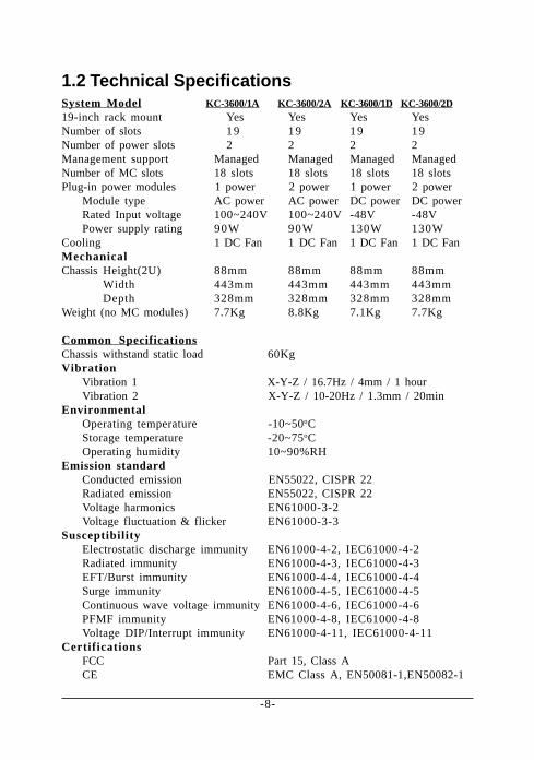
1.2 Technical SpecificationsSystem Model KC-3600/1A KC-3600/2A KC-3600/1D KC-3600/2D19-inch rack mount Yes Yes Yes YesNumber of slots 19 19 19 19Number of power slots 2 2 2 2Management support Managed Managed Managed ManagedNumber of MC slots 18 slots 18 slots 18 slots 18 slotsPlug-in power modules 1 power 2 power 1 power 2 power
Module type AC power AC power DC power DC powerRated Input voltage 100~240V 100~240V -48V -48VPower supply rating 90W 90W 130W 130W
Cooling 1 DC Fan 1 DC Fan 1 DC Fan 1 DC FanMechanicalChassis Height(2U) 88mm 88mm 88mm 88mm
CertificationsFCC Part 15, Class ACE EMC Class A, EN50081-1,EN50082-1
-9-
AC Power Chassis Module KC3600-AC SpecificationsDimension 298.2mm x 160.6mm x 40.6mmInstallation method Plug in from system rear panelMaintenance Modular design for easy maintenanceAC power switch System power on/off switchAC power receptacle IEC320 type receptacleElectric
Input voltage rating 100 ~ 240VACInput voltage range 90 ~ 264VACInput frequency 47 ~ 63HzInput surge current 30A max. @115VACOutput power 90W (5V and 3.3V)
Protection Over voltage, over power, short circuitSafety UL1950, TUV EN60950Insulation Resistance >10M Ohm @DC500VDielectric withstands 1500VAC 10mA 1min.
DC Power Chassis Module FC3600-DC SpecificationsDimension 298.2mm x 160.6mm x 40.6mmInstallation method Plug in from system rear panelMaintenance Modular design for easy maintenanceInput power switch System power on/off switchInput power receptacle Terminal connector (screw type)Electric
Input voltage rating -48VDCInput voltage range -36 ~ -75VDCEfficiency 73% full loadOutput power rating 130W
Protection Output overvoltage protectionShort circuit protectionOver temperature protection (auto-restart)
Management Module SpecificationsDimension 156.5mm x 44.4mm x 86.4mmSlot position Slot 0CPU RISC-based ARM7RAM size 1M bytesFlash size 512K bytesSystem interface
Connector DIN type connectorConsole interface
Interface RS-232 DTEConnector 9-pin male D-SUB connectorBaud rate 38400, N, 8, 1, 0Flow control Disabled
In-band interfaceInterface 10/100M LAN portConnector Shielded RJ-45 MDIStandard IEEE 802.3 10BASE-T/100BASE-TXAuto-negotiation Support
LED IndicatorsPOWER Green LED, module power statusINIT. Green LED, CPU initializationCONSOLE Green LED, Console RS-232 Rx activitiesLNK/ACT. Green LED, LAN port link and activities status
Slide-in Media Converter Modules Supported10/100TX to 100FX Media Converter series10BASE-T to 10BASE-FL Media Converter series1000BASE-T to 1000BASE-SX Media Converter series1000BASE-T to 1000BASE-LX Media Converter series
Refer to the separated user manual for 3600 media converter modules for moreinformation.
-11-
Management SpecificationsManagement interface
Telnet Via direct RS-232 console connectionTelnet Via TCP/IP Telnet softwareSNMP agent Via TCP/IP SNMP manager softwareHTTP server Via web browser software
ProtocolsIPv4 IP version4 RFC791TCP Transmission Control Protocol RFC793UDP User Datagram Protocol RFC768ICMP Internet Control Message Protocol RFC792SNMP SNMP agent v1 RFC1157MIB-II Standard MIB RFC1213T F T P Trivial File Transfer Protocol RFC1350TELNET Telnet protocol RFC854H T T P HTTP server for web management RFC1945
Management ObjectsPassword for access control Set and monitorSystem status : CPU, memory, flash, software MonitorSystem power 1&2 status MonitorSystem power 1&2 temperature status MonitorSystem fan status MonitorIP address of the system Set and monitorSubnet mask of the system Set and monitorDefault gateway IP address Set and monitorSNMP name information Set and monitorSNMP location information Set and monitorSNMP contact information Set and monitorSNMP community names (up to 4) Set and monitorSNMP community access right (up to 4) Set and monitorSNMP trap host IP address (up to 3) Set and monitorSlot status : MC module installed or not MonitorMC Module status : media type, speed, duplex MonitorMC Module link status of two ports Monitor
SNMP TrapsCold Start System is powered on and completes initializationAuthentication failure SNMP community authentication failurePower status The system power 1&2 failure and recoveryTemperature status Power 1&2 temperature warning and recoveryFan failure System fan failure and recoverySlot # Port A link Slot # MC module Port A link down or upSlot # Port B link Slot # MC module Port B link down or up
Update Firmware Via TFTP protocolRemote boot system
-12-
2. Installation
2.1 UnpackingThe product package contains:• The system unit
• One power cord
• One 19-inch rack mounting kit
• Operation Manual
2.2 System UnitsThe figure below illustrates the front view of the KC-3600 system:
Depending on the model purchased, the type and numbers of the pre-installed media converter modules may be different. The figure shows asystem which is fully installed with media converter modules.
The following figures show the rear view of the KC-3600 system. Themain chassis provides two power chassis slots on the rear panel. Eachpower chassis slot can be installed with one AC power chassis or one DCpower chassis. Two power slots design features the system a powerredundant function.
-13-
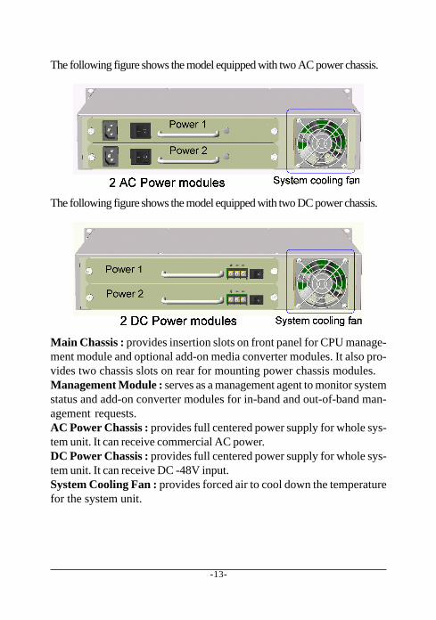
The following figure shows the model equipped with two AC power chassis.
The following figure shows the model equipped with two DC power chassis.
Main Chassis : provides insertion slots on front panel for CPU manage-ment module and optional add-on media converter modules. It also pro-vides two chassis slots on rear for mounting power chassis modules.Management Module : serves as a management agent to monitor systemstatus and add-on converter modules for in-band and out-of-band man-agement requests.AC Power Chassis : provides full centered power supply for whole sys-tem unit. It can receive commercial AC power.DC Power Chassis : provides full centered power supply for whole sys-tem unit. It can receive DC -48V input.System Cooling Fan : provides forced air to cool down the temperaturefor the system unit.
-14-
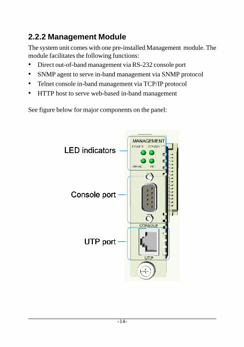
2.2.2 Management ModuleThe system unit comes with one pre-installed Management module. Themodule facilitates the following functions:• Direct out-of-band management via RS-232 console port
• SNMP agent to serve in-band management via SNMP protocol
• Telnet console in-band management via TCP/IP protocol
• HTTP host to serve web-based in-band management
See figure below for major components on the panel:
-15-
Console PortThis port is a 9-pin male D-sub connector. It serves as an RS-232 DTE port.Refer to Chapter xx for the console operation. The pin definitions are:
Pin2 RXDPin 3 TXDPin 4 DTRPin 5 GNDPin 6 DSR
UTP PortThis is an auto-negotiation 10/100BASE-TX LAN port and provides ashielded RJ-45 jack with MDI definition. This port must connect to yourTCP/IP network for all in-band management operations.
LED Indicators Color States InterpretationPOWER Green On System is powered onCONSOLE Green On Tx activities of console portLNK/ACT Green On UTP port link is active
Green Blink Tx/Rx activities of UTP portINIT Green On SNMP module in initialization
-16-
2.2.3 Power Chassis ModulesThe system power supply is assembled in a plug-in chassis module. Twotypes of system power chassis are illustrated as follows:
Each single power module is capable to supply full power for systemoperation with full media converter modules installed.
AC Power Chassis Specifications (KC3600-AC-)AC power switch System power on/off switchAC power receptacle IEC320 type receptacleInput voltage rating 100 ~ 240VACInput voltage range 90 ~ 264VACInput frequency 47 ~ 63HzOutput power 90WAC power cord IEC320 type power cordOver temperature Protection Over 70±5oC send warning signal to CPU
Below 45±10oC recovery automatically
-17-
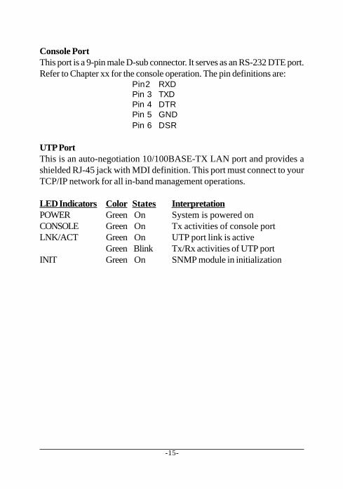
DC Power Chassis Specifications (KC3600-DC)Input power switch System power on/off switchInput power receptacle Terminal connector (screw type)Input voltage rating -48VDCInput voltage range -36 ~-75VDCOutput power 130WOver temperature Protection Over 70±5oC send warning signal to CPU
Below 45±10oC recovery automatically
The connection definition of the DC power receptacle is:
-18-
Removal of System Power ChassisThe system power chassis is pre-installed in the system unit when sys-tem unit is shipped from factory. The chassis is designed for easy un-installation from system unit in case of any inspection purpose. How-ever, note that this removal only can be performed by a well-trainedtechnical person.
For safety reason before removing the power chassis, make sure:• The power switch is turned off.
• The power cord is disconnected from the power chassis.
To remove the chassis, unscrew two chassis screws until they are re-leased from system chassis, hold the handle and pull the chassis outfrom the system chassis smoothly. See the following example figure:
-19-
Insertion of System Power ChassisBefore inserting the power chassis into system unit, make sure:• The system power switch is turned off.
• The power cord is disconnected from the power chassis.
To insert the power chassis, hold the handle and push it into system unituntil it is seated in system chassis properly. Screw the chassis securely inthe system unit. See figure below:
The power chassis is designed to be hot plugged into or unpluggedfrom the system even when another power chassis is installed inanother power slot and in operation.
-20-
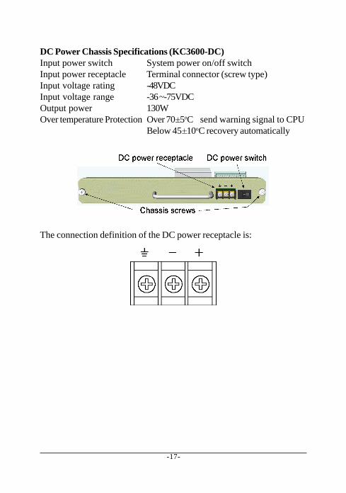
2.2.4 System Cooling FanThe system chassis provides one cooling fan. The operation status ofthe fan can be monitored via all supported management interfaces.
It is also featured with mechanical design to be removed and installedwithout opening the system chassis.
The procedure to remove the fan is:
1. Unscrew four fan screws as shown below:
2. Unplug the fan cable.
Reverse the above steps to install the fan. The fan can be removed orinstalled even when the system is in operation.
-21-
2.2.5 Media Converter SlotsThe system chassis provides eighteen module slots for installing op-tional slide-in media converter modules.
A media converter module can be inserted into an available slot or re-moved from a slot anytime even when system unit is powered on. Thishot-plug design keeps all exiting connections on the other slots runningwith no influence.
To insert a converter module into a slot, remove slot cover first and insertthe module into slot slowly until it is seated in slot properly. Screw it ontosystem unit securely before making any cable connection.
-22-
To remove a converter module from slot, disconnect all cable connec-tions on the module first and unscrew the module until it is released fromsystem unit. Hold the screw and pull module slowly out from the slot.
The media converter modules are designed with hot-plug feature, whichallows insertion and removal of the modules can be performed evenwhen the system is in operation.
The following figure illustrates an example of a media converter module:
For more information about the converter slide-in module, refer to Chap-ter 7 and Chapter 8.
-23-
2.3 Rack MountingOne rack mounting kit is supplied in the product package. It includes twobrackets and bracket screws for installing the system unit into a 19-inch rack.
Mount both brackets onto the system unit as shown below:
Install the system unit into a 19-inch rack as shown below:
-24-
3. Network Management
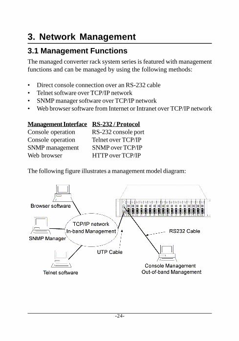
3.1 Management FunctionsThe managed converter rack system series is featured with managementfunctions and can be managed by using the following methods:
• Direct console connection over an RS-232 cable• Telnet software over TCP/IP network• SNMP manager software over TCP/IP network• Web browser software from Internet or Intranet over TCP/IP network
Management Interface RS-232 / ProtocolConsole operation RS-232 console portConsole operation Telnet over TCP/IPSNMP management SNMP over TCP/IPWeb browser HTTP over TCP/IP
The following figure illustrates a management model diagram:
-25-
The system unit is equipped with one management module which servesas a management agent to monitor the system status and all installedmedia converter modules. The agent also responses to either in-bandmanagement requests coming from network or out-of-band requests fromdirectly connected console.
3.2 Protocols SupportedProtocols Name ReferenceIPv4 IP version4 RFC791TCP Transmission Control Protocol RFC793UDP User Datagram Protocol RFC768ICMP Internet Control Message Protocol RFC792SNMP SNMP agent v1 RFC1157MIB-II Standard MIB RFC1213TFTP Trivial File Transfer Protocol RFC1350TELNET Telnet protocol RFC854HTTP HTTP server for web management RFC1945
-26-
3.3 Setup for Out-of-band (Console) ManagementBefore doing any in-band management, it is necessary to perform con-sole operation for configuring IP and SNMP related settings for the firsttime the system is received for installation. The console port is locatedon the SNMP module.
Any PC running Windows 95/98/ or NT can be used as a console viaCOM port. Windows Hyper Terminal program is an ideal and the mostpopular software for such console terminal operations.
To setup console operation, the steps are:1. Find a proper RS-232 cable for the connection to a console terminal.
If your are using PC as a terminal, make sure the cable pin assign-ments comply to the following requirement.
Console port 9-pin PC COM portPin2 RXD -------------------------------- 3
2. Connect one end to the console port and connect the other end tothe PC COM port.
3. Configure your PC COM port setting to match the RS-232 settings ofthe console port and start your terminal software.
Factory default settings of the Console portBaud rate : 38400, N, 8, 1, 0Flow control : disabled
4. Turn the system power on.
5. Press <Enter> key several times in your terminal software until alogin prompt comes up. It means the connection is proper.
The console port does not support modem connection.
Refer to Chapter 4 for more information about Console management.
-28-
3.4 Setup for In-band ManagementTo perform an in-band management, it is necessary to connect the sys-tem to your TCP/IP network. The steps are:
1. Configure IP and SNMP related settings to the system using directconsole management when you receive it first time for the installa-tion.
2. Find a proper straight-through Category 5 UTP cable (maximal length100 meters) for the connection.
3. Connect one end of the UTP cable to the UTP port on SNMP moduleand connect the other end to the device, such as a switching hub, inyour TCP/IP network.
4. Start your in-band management operations. For different manage-ment methods, refer to:
• Chapter 4 for Telnet management
• Chapter 5 for SNMP management
• Chapter 6 for Web management
-29-
4. Console and Telnet OperationFunctions supported:• Set and display IP parameters for the system.
• Set and display SNMP parameters for the SNMP agent function.
• Monitor system power status, power temperature status, systemfan status and other system information.
• Monitor installation status of each slots.
• Monitor the configuration and link status of each module installed.
• Restore default settings for the system
• Change administrator password for access control.
• Update system software.
• Reboot (warm start) the system remotely.
Management ObjectsObjects Modify MonitorPassword for access control Y -System : CPU, memory, flash, software version - YPower 1&2 status - YPower temperature 1&2 status - YSystem fan status - YIP address of the system Y YSubnet mask of the system Y YDefault gateway IP address Y YSNMP name Y YSNMP location Y YSNMP contact Y YSNMP community name (up to 4) Y YSNMP community access right (up to 4) Y YSNMP trap host IP address (up to 3) Y YSlot status : module installed or not - YModule status : media type, speed, duplex - YModule link status of two ports - Y
-30-
Cold StartWhen the power to the system is turned on, the system start initializationand self-test process. The self-test messages are displayed as follows ifa console connection is established successfully.:
This chapter describes the detailed console operation. It can be appliedto either out-of-band console management or in-band Telnet manage-ment. Both are same in operation starting from login prompt.
-31-
Direct Console ManagementWhen you can see the self-test messages shown on screen properly, youcan press <Enter> key to start console login operation. Go to LoginPrompt section in next page directly.
Telnet ManagementUse Telnet software to perform the management operation. The mostconvenient solution is using the built-in Telnet function in a Windows95/98/ or NT PC. Enter into DOS window and invoke Telnet command :
>telnet xxx.xxx.xxx.xxx
to connect to the system unit. The specified xxx.xxx.xxx.xxx is the IP ad-dress of the system unit. A welcome message and login prompt are dis-played if the connection is established properly.
Login PromptThe following figure illustrates the login screen:---------------------------------------------
Welcome to Console
login:admin
password:***
---------------------------------------------
Username : adminFactory default Password : 123
For security reason, the system supports a function to change the pass-word in setup menu. It is recommended to change the default passwordimmediately after a successful login.
-32-
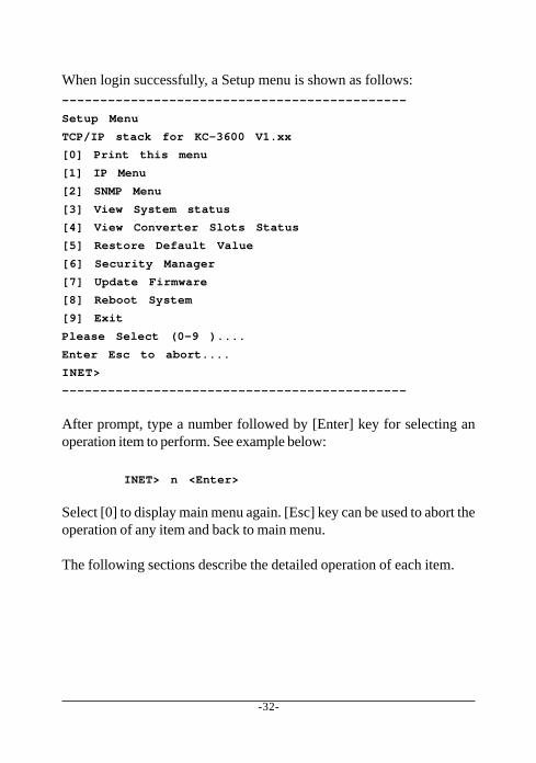
When login successfully, a Setup menu is shown as follows:---------------------------------------------
Setup Menu
TCP/IP stack for KC-3600 V1.xx
[0] Print this menu
[1] IP Menu
[2] SNMP Menu
[3] View System status
[4] View Converter Slots Status
[5] Restore Default Value
[6] Security Manager
[7] Update Firmware
[8] Reboot System
[9] Exit
Please Select (0-9 )....
Enter Esc to abort....
INET>
---------------------------------------------
After prompt, type a number followed by [Enter] key for selecting anoperation item to perform. See example below:
INET> n <Enter>
Select [0] to display main menu again. [Esc] key can be used to abort theoperation of any item and back to main menu.
The following sections describe the detailed operation of each item.
-33-
4.1 IP MenuSelect [1] from Setup menu to set IP related settings.---------------------------------------------
IP Menu
[0] Print this menu
[1] Set IP Address
[2] View IP Status
[3] Exit
Please Select (0-3)
---------------------------------------------
Set IP Address----------------------------------------------------------------------
Enter ESC to abort.
Please Input IP Address(xxx.xxx.xxx.xxx):192.168.0.23
replacing net[0] IP address nnn.nnn.nnn.nnn with 192.168.0.23
IP Address : Unique IP address designated to this systemSubnet Mask : The subnet mask of the IP address specified aboveGateway : The IP address of the default gateway (router)
Note that all current in-band network management connections on thesystem will be killed if system IP address is changed. This change doesnot affect the operation of the media converter modules in slots.
View IP Status-----------------------------------------------IP Addr: 192.168.0.23 Submask: 255.255.255.0 Gateway: 192.168.0.1
-----------------------------------------------
-34-
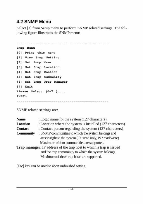
4.2 SNMP MenuSelect [3] from Setup menu to perform SNMP related settings. The fol-lowing figure illustrates the SNMP menu:
---------------------------------------------
Snmp Menu
[0] Print this menu
[1] View Snmp Setting
[2] Set Snmp Name
[3] Set Snmp Location
[4] Set Snmp Contact
[5] Set Snmp Community
[6] Set Snmp Trap Manager
[7] Exit
Please Select (0-7 )....
INET>
---------------------------------------------
SNMP related settings are:
Name : Logic name for the system (127 characters)Location : Location where the system is installed (127 characters)Contact : Contact person regarding the system (127 characters)Community : SNMP communities to which the system belongs and
access right to the system ( R : read only, W : read/write) Maximum of four communities are supported.
Trap manager: IP address of the trap host to which a trap is issued and the trap community to which the system belongs. Maximum of three trap hosts are supported.
[Esc] key can be used to abort unfinished setting.
-35-
4.3 View System StatusSelect [4] from Setup menu to view system status. The system status areshown as follows:
---------------------------------------------Power 1 Status: Good , Power 2 Status: Good
Temperature 1 Status :Normal , Temperature 2 Status :Normal
FAN status: Good
CPU status:
Cpu Type = ARM7, Flash Size = 512K, Sdram Size = 2M Bytes
Software version 1.xx
---------------------------------------------
Power status indicates the status of system power 1&2 chassis.Power Status : Good, Bad
Temperature status indicates the temperature status of the system power1&2 chassis.Temperature Status : Normal, Warning
FAN status indicates the status of system cooling fan.FAN Status : Good, Bad
CPU information and software version are static information for refer-ence.
-36-
4.4 View Converter Slots StatusSelect [5] from setup menu to view current status of all media convertermodules in the system. The slot status are shown as follows:
Column States InterpretationSlot 01-18 Slot position in the system
Slot #1 - slot #18 are for media converter module
Port N/A No module is installed in slotA Upper port of the module in slotB Lower port of the module in slot
Media N/A No module is installed in slot.TX 10BASE-T, 10/100BASE-TX port or 1000BASE-T portFX 10BASE-FL, 100BASE-FX port or 1000BASE-SX/LX port
Speed N/A No module is installed in slot10M 10Mbps100M 100Mbps1000M 1000Mbps
Duplex N/A No module is installed in slot.Full Full duplexHalf Half duplex
Link N/A No module is installed in slot.Up Link upDown Link down
-38-
4.5 Restore Default ValuesSelect [6] from Setup menu to restore factory default settings.
Factory default settings are:
IP Address 192.168.0.2
Subnet Mask 255.255.255.0
Default Gateway 192.168.0.1
User Name admin
Password 123
Name (null)
Location (null)
Contact (null)
SNMP Communities:
No.1 Community name public
No.1 Access right Read only
No.2 Community name (null)
No.2 Access right (N/A)
No.3 Community name (null)
No.3 Access right (N/A)
No.4 Community name (null)
No.4 Access right (N/A)
SNMP Trap Managers:
No.1 Trap manager IP (null)
No.1 Community name (null)
No.2 Trap manager IP (null)
No.2 Community name (null)
No.3 Trap manager IP (null)
No.3 Community name (null)
-39-
4.6 Security ManagerSelect [7] from Setup menu to change login user name and password.
The steps are:
Display current user name---------------------------------------------
Current username: admin
Current password: ********
Press Esc to abort ....
---------------------------------------------
Change user name and password---------------------------------------------
Change username [admin]: xxxxxx
Enter password(1-8): ********
Confirm password: ********
Password updating .......
Password updated.
INET>
---------------------------------------------
-40-
4.7 Update FirmwareSelect [7] from Setup menu to perform firmware (system software) up-grade via TFTP protocol. Before doing TFTP operation, one TFTP serveris required and installed in the network to where this system connectsand new firmware file image.bin must be placed in the TFTP server.
The following information are required for TFTP operations:
TFTP Server IP Address: IP address of the TFTP server where thefirmware image.bin is downloaded from.
-41-
The steps are:Specify TFTP server IP address---------------------------------------------Enter ESC to abort.
Please Input TFTP Server IP Address (xxx.xxx.xxx.xxx):192.168.0.88
TFTP Server: 192.168.0.88
---------------------------------------------Confirm to start downloading---------------------------------------------Do you want to start download new image ? (Y/N) Y
Download image and please wait........
---------------------------------------------Confirm to update system flash memory---------------------------------------------Download new image complete, do you want to update flash ? (Y/N) Y
Update flash and please wait ....
Update flash complete and please reboot system !
INET>
---------------------------------------------
4.8 Reboot SystemSelect [8] from Setup menu to reboot the system. This reboot functionallows you to perform a warm start to the system.
---------------------------------------------Do you want to reboot system ? (Y/N) Y
---------------------------------------------
-42-
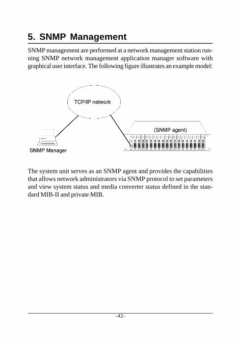
5. SNMP ManagementSNMP management are performed at a network management station run-ning SNMP network management application manager software withgraphical user interface. The following figure illustrates an example model:
The system unit serves as an SNMP agent and provides the capabilitiesthat allows network administrators via SNMP protocol to set parametersand view system status and media converter status defined in the stan-dard MIB-II and private MIB.
-43-
5.1 Configuring SNMP Settings via Console OperationBefore performing SNMP operation, proper SNMP settings must be con-figured in the system unit. The SNMP related settings are:
Name : Logic name to identify a specific system unit
Location : Location where the system is installed
Contact : Contact person regarding the system
Community : SNMP communities to which the system belongs
and access right to the system ( read only or read/write)
Trap hosts : IP addresses of trap hosts to which a trap is issued
and the trap community to which the system belongs.
Up to four SNMP communities and up to three trap hosts are supportedby the system SNMP agent.
These settings can be configured through console or telnet operation.Refer to Chapter 4 for more information.
-44-
5.2 SNMP Private MIBUse the SNMP management application software to compile the MIB filefirst before performing any management operation. In addition to stan-dard MIB-II (RFC1213), the system supports private MIB as below:
Private MIB Objects Get RemarkssPowerStatus(kti.30.1.1) Y Power 1&2 statusssTempStatus(kti.30.1.2) Y Temperature 1&2 statusssFanStatus(kti.30.1.3) Y System fan statuscputype(kti.30.2.1) Y ARM7flashrom(kti.30.2.2) Y 512KBmemsize(kti.30.2.3) Y 2MBsoftwarever(kti.30.2.4) Y 1.xxmibFileVer(kti.30.2.5) Y 1.xxportNumber(kti.30.3.1) Y Total number of slotsportTable(kti.30.3.2) -portEntry(1) -slotIndex(1) Y Slot ID 1 - 18slotIndexDescription(2) Y Slot1 - Slot18slotModuleDescription(3) YslotModuleType(4) YsotModuleStatus_PortA_Media(5) Y Port A media typeslotModuleStatus_PortA_LineSpeed(6) Y Port A line SpeedslotModuleStatus_PortA_Duplex(7) Y Port A duplex modeslotModuleStatus_PortA_LinkStatus(8) Y Port A Link statusslotModuleStatus_PortB_Media(9) Y Port B media typeslotModuleStatus_PortB_LineSpeed(10) Y Port B line speedslotModuleStatus_PortB_Duplex(11) Y Port B duplex modeslotModuleStatus_PortB_LinkStatus(12) Y Port B link status
Remark: Port A : the upper port of the converter modulePort B : the lower port of the converter module
Refer to MIB file, KC3600-v1.xx.mib for the details. This file can be usedfor MIB compiler.
-45-
5.3 SNMP TrapsThe system also supports the following SNMP traps. When the trapevent occurs, the SNMP agent will generate a trap notification to SNMPmanagement station.
Trap Name Event of Trap GeneratedCold Start The system is powered on and complete
initializationAuthentication failure SNMP community authentication failurePower status Any power failure of Power1and Power2Power status Any power recovery of Power1 and Power2Temperature status Any temperature wanring of Power1 & Power2Temperature status Any temperature recovery of Power1 & Power2Fan status Fan failureFan status Fan recoverySlot # Port A link Slot # module Port A link down or upSlot # Port A link Slot # module Port A link recoverySlot # Port B link Slot # module Port B link down or upSlot # Port B link Slot # module Port B link recovery
The binding information together with a trap is :
Trap Name VarBindCold Start sysDescr, ie KC-3600Authentication failure sysDescr, ie, KC-3600Power Status Power status for Power1 and Power2Temperature Status Temperature status for Power1 and Power2Fan Status Fan statusSlot # Port A link Slot description and Port A link statusSlot # Port B link Slot description and Port B link status
Remark: The slot # can be slot 1 up to slot 18.Port A : the upper port of the module installed in slot.Port B : the lower port of the module installed in slot.
-46-
6. Web ManagementThe system features an http server which can serve the managementrequests coming from any web browser software over internet or intranetnetwork.
Web BrowserCompatible web browser software with JAVA supportMicrosoft Internet Explorer 4.0 or laterNetscape Communicator 4.x or later
Set IP Address for the System UnitBefore the system can be managed from a web browser software, makesure a unique IP address is configured to the system. Refer to Chapter 4for how to set IP address.
6.1 Start Browser Software and Making ConnectionStart your browser software and enter the IP address of the system unitto which you want to connect. The IP address is used as URL for thebrowser software to search the device.
URL : http://xxx.xxx.xxx.xxx/
Factory default IP address : 192.168.0.2
-47-
6.2 Login to the System UnitWhen browser software connects to the system unit successfully, aLogin screen is provided for you to login to the device as follows:
Login
Username : AdminFactory default Password : 123
-48-
The following screen shows welcome screen when a successful login isperformed.
In addition to the device image, the screen supports the following func-tions on the right side:
1. Home : home page and device image2. Converter Status : view all slot status3. System Status : view system related status4. Administrator : other management functions
-49-
6.3 Converter Status
Click [Converter Status] to view all slot status in a table list. The informa-tion includes:
-50-
Column States InterpretationSlot 1-18 Slot position in the system
Slot #1 - slot #18 are for media converter module
Port A Upper port of the module in slotB Lower port of the module in slot
Media TX 10BASE-T, 10/100BASE-TX, 1000BASE-T portFX 100BASE-FL, 100BASE-FX, 1000BASE-SX/LX port
Link Green Link upRed Link down
Speed 10Mbps 10BASE-T or 10BASE-FL100Mbps 100BASE-TX or 100BASE-FX1000Mbps1000BASE-T or 1000BASE-SX/LX
Duplex Full Full duplexHalf Half duplex
-51-
6.4 System Status
Click [System Status] to view system related status in a table list. Theinformation includes:
Slot Number : slot number where the status belongs toPower Status : system power 1&2 chassis conditionTemperature : system power 1&2 temperature statusFAN Status : system fan statusCPU type : CPU model equipped in management moduleRAM size : Memory size equipped in management moduleFlash size : Flash memory equipped in management moduleSoftware version : Software version built in management module
-52-
6.5 Administrator Menu
Click [Administrator] to show administrator menu. The menu includesthe following options:
1. Basic : Set / View IP and SNMP related settings2. Console Port Information : View RS-232 console configuration3. Security Manager : Change login user name and password4. Image Refresh Time : Set refresh time interval of the image5. Update Firmware : Update the software built in SNMP module6. Reboot System : Reboot the system remotely
Refer to the following sections for the details.
-53-
6.5.1 BasicClick [Basic] to perform IP setting and SNMP settings.
IP setting and SNMP setting are described in the following sectionsrespectively.
-54-
Click [IP Address] button to set IP settings.
IP settings include:
IP Address : Unique IP address designated to this systemSubnet Mask : The subnet mask of the IP address specified aboveGateway : The IP address of the default gateway (router)
Click [Update Settings] to make new settings effective. However, a newIP address change will make your current connection invalid. Restartyour web link with new IP address to connect the system.
-55-
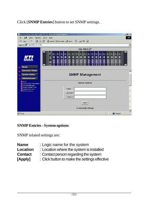
Click [SNMP Entries] button to set SNMP settings.
SNMP Entries - System options
SNMP related settings are:
Name : Logic name for the systemLocation : Location where the system is installedContact : Contact person regarding the system[Apply] : Click button to make the settings effective
-56-
SNMP Entries - Community Strings
One community contains two settings:
Community name : SNMP communities to which the system belongsAccess right : Access right associated with the community name
Click [Add] button to add one new community into the community list.Click [Remove] button to remove one community from the community list.
Up to four entries are supported in the community list.
-57-
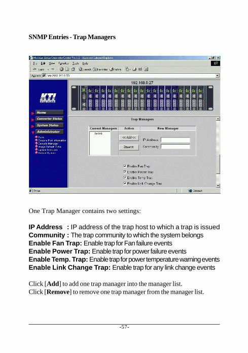
SNMP Entries - Trap Managers
One Trap Manager contains two settings:
IP Address : IP address of the trap host to which a trap is issuedCommunity : The trap community to which the system belongsEnable Fan Trap: Enable trap for Fan failure eventsEnable Power Trap: Enable trap for power failure eventsEnable Temp. Trap: Enable trap for power temperature warning eventsEnable Link Change Trap: Enable trap for any link change events
Click [Add] to add one trap manager into the manager list.Click [Remove] to remove one trap manager from the manager list.
-58-
6.5.2 Console Port Information
This screen displays configuration of RS-232 console port.
-59-
6.5.3 Security Manager
Security Manager allows you to change login user name and password.Click [Apply] to make the changes effective.
-60-
6.5.4 Image Refresh Time
The system image is updated periodically to present the latest status.The default time interval of refreshing the image is 20 seconds. It can bechanged by clicking any of the time buttons displayed. This is a run timesetting and not a permanent setting.
-61-
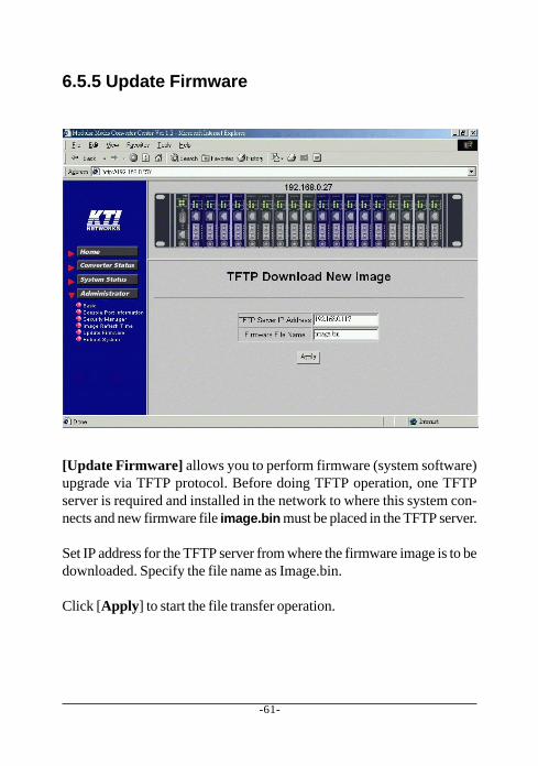
6.5.5 Update Firmware
[Update Firmware] allows you to perform firmware (system software)upgrade via TFTP protocol. Before doing TFTP operation, one TFTPserver is required and installed in the network to where this system con-nects and new firmware file image.bin must be placed in the TFTP server.
Set IP address for the TFTP server from where the firmware image is to bedownloaded. Specify the file name as Image.bin.
Click [Apply] to start the file transfer operation.
-62-
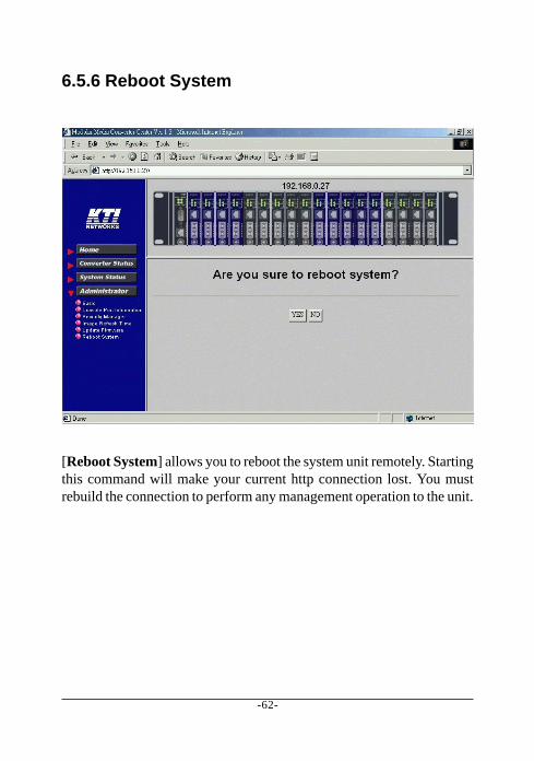
6.5.6 Reboot System
[Reboot System] allows you to reboot the system unit remotely. Startingthis command will make your current http connection lost. You mustrebuild the connection to perform any management operation to the unit.
-63-
6.6 Slot Icon OperationsIn addition to the menu supported, you may click the following imageicons to show specific status.
Click slot 0 on the system image shown on screen
Power Status : system power 1&2 conditionTemperature : system power 1&2 temperature statusFan Status : system fan statusCPU type : CPU model equipped in management moduleRAM size : Memory size equipped in management moduleFlash size : Flash memory equipped in management moduleSoftware version : Software version built in management module
-64-
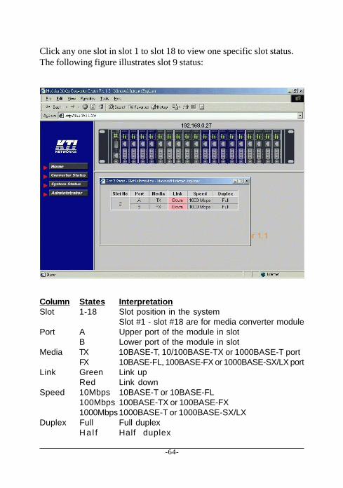
Click any one slot in slot 1 to slot 18 to view one specific slot status.The following figure illustrates slot 9 status:
Column States InterpretationSlot 1-18 Slot position in the system
Slot #1 - slot #18 are for media converter modulePort A Upper port of the module in slot
B Lower port of the module in slotMedia TX 10BASE-T, 10/100BASE-TX or 1000BASE-T port
FX 10BASE-FL, 100BASE-FX or 1000BASE-SX/LX portLink Green Link up
Red Link downSpeed 10Mbps 10BASE-T or 10BASE-FL
100Mbps 100BASE-TX or 100BASE-FX1000Mbps1000BASE-T or 1000BASE-SX/LX


![STATCOM BASED ON MODULAR MULTILEVEL CONVERTER: …strathprints.strath.ac.uk/40646/7/Adam_etal_IET... · source modular multilevel converter is adopted to FACTS devices[1, 5, 8-11].](https://static.documents.pub/doc/80x56/5f05593f7e708231d41285c5/statcom-based-on-modular-multilevel-converter-source-modular-multilevel-converter.jpg)


