18
Dylan Morgan Student Number: 587256 Semester: 1/2012 Group: 7 Module 3
| Date post: | 28-Mar-2016 |
| Category: |
Documents |
| Upload: | dylan-morgan |
| View: | 212 times |
| Download: | 0 times |

Dylan Morgan
Student Number: 587256 Semester: 1/2012 Group: 7
Module 3

Continuation from module 2: Introduction
Following Module 2 I was faced with several problems in regards to the overall direction of my lantern, in addition to problems with potential fabrication techniques.
As shown in these pictures, demonstrating the development of the lantern through module 2, the paneling has curved faces. It is not possible to unfold and construct this paneling, I therefore needed to develope an appropriate surface.
Below:The final form developed through module 2, demonstrating the inability to construct the paneling I created

Panelling for fabrication: Development
In module 2 I experienced problems when creating an even paneling grid on surface. For this reason I returned to the initial lofted surface and applied a paneling grid to it without attempting to smooth the surface as I did in module 2.
This allowed me to develope a relatively simple pyramid pan-eling surface. I had hoped to keep the density of the pan-eling minimal to retain the simplicity of the rigid form, as I felt that when I moved onto developing the fluid form it would become quite busy.
Below:Using the offset faces border tool I tried to replicate the transition of light that was developed in line with the involvement of light in my natural process. the picture emediately below demonstrates this (i.e. the three distinct stages- some light, almost no light and then all light as the creature emerges (right to left))

Panelling for fabrication: final form
By dividing up the surface and using point attractors through the offset faces border tool I created the final form that in-corporated the features I had hoped for:
simple and rigid transition of light

Fluid form development: Introduction
As I demonstrated at the end of my module 2 submission, I wanted to panel a fluid form that extended from the open-ing in the rigid form, representing the moth that exists and emerges from its rigid cocoon made from sticks.
Shown alongside is the possibility of integrating the two forms by passing the fluid form through to openings created by using the offset faces border tool

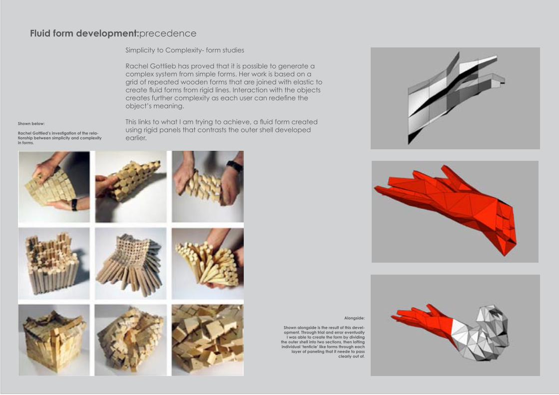
Fluid form development:precedence
‘Cosmic Leaf’
Cosmic Leaf by British designer Ross Lovegrove features its fluid form that is illuminated from a light source on top to the meshed skin.
This light demonstrates the fluidity that can be created by a rigid material. This is the aspect that I had hoped to replicate.
‘Cosmic Leaf’ by Ross Lovegrove, 2009
Above:
The development of a lofted form that extends from the outer surface.
Fluid form development:precedence
Simplicity to Complexity- form studies
Rachel Gottlieb has proved that it is possible to generate a complex system from simple forms. Her work is based on a grid of repeated wooden forms that are joined with elastic to create fluid forms from rigid lines. Interaction with the objects creates further complexity as each user can redefine the object’s meaning.
This links to what I am trying to achieve, a fluid form created using rigid panels that contrasts the outer shell developed earlier.
Alongside:
Shown alongside is the result of this devel-opment. Through trial and error eventually
I was able to create the form by dividing the outer shell into two sections, then lofting individual ‘tenticle’ like forms through each
layer of paneling that it neede to pass clearly out of.
Shown below:
Rachel Gottlied’s investigation of the rela-tionship between simplicity and complexity in forms.

Fluid form development:
Pictured are the two contrasting forms placed together, with the fluid form in red to highlight the end result.
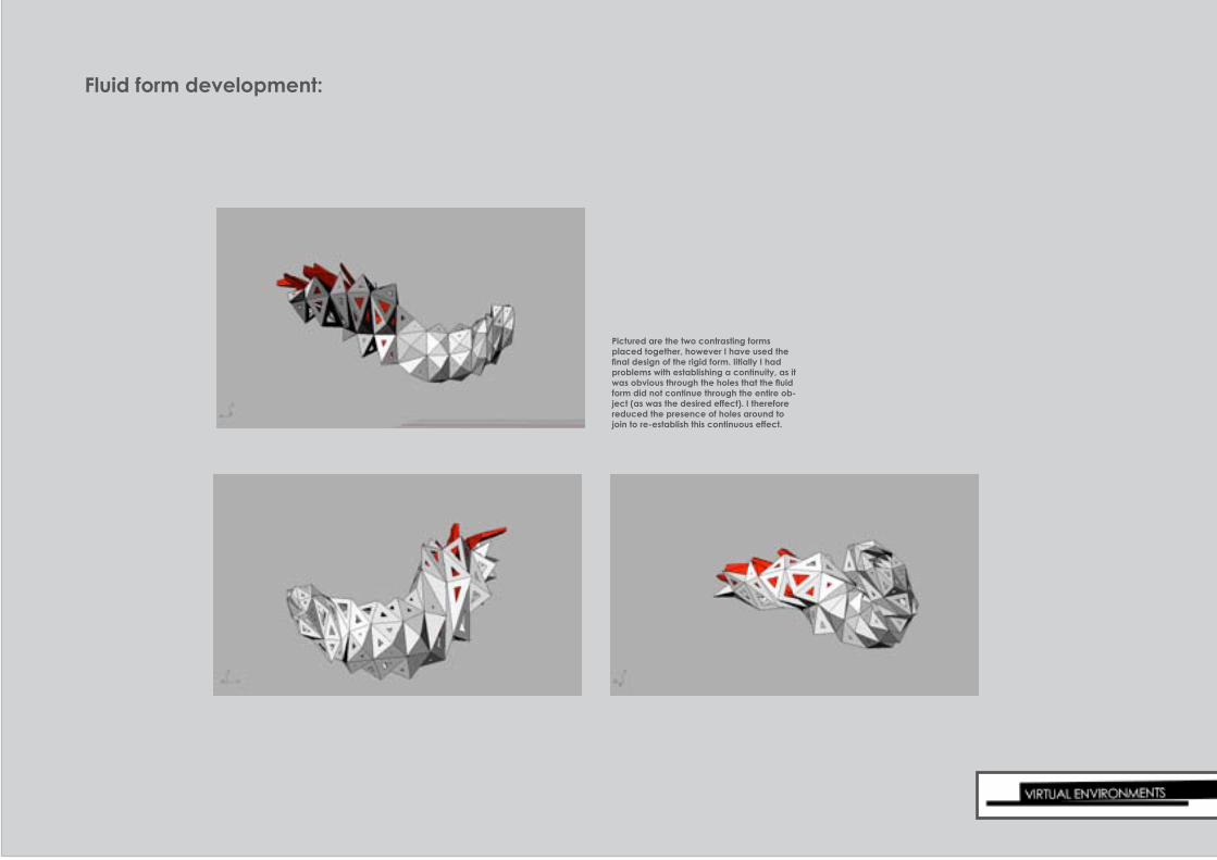
Fluid form development:
Pictured are the two contrasting forms placed together, however I have used the final design of the rigid form. Iitially I had problems with establishing a continuity, as it was obvious through the holes that the fluid form did not continue through the entire ob-ject (as was the desired effect). I therefore reduced the presence of holes around to join to re-establish this continuous effect.

Fabrication: Unrolling surfaces (rigid form)
In order to fabricate the lantern I needed to unroll the two surfaces and construct them individually.
As shown alongside this would need to be done in sections to avoid overlapping
Left:
Pictured is the result of unrolling the entire rigid surface (shown top left) as one piece..

Fabrication: Unrolling surfaces (rigid form)
I divided the rigid outer surface into rings, with a long spinal piece (shown in red) to aid in construction of the model

Fabrication: Unrolling surfaces (rigid form)
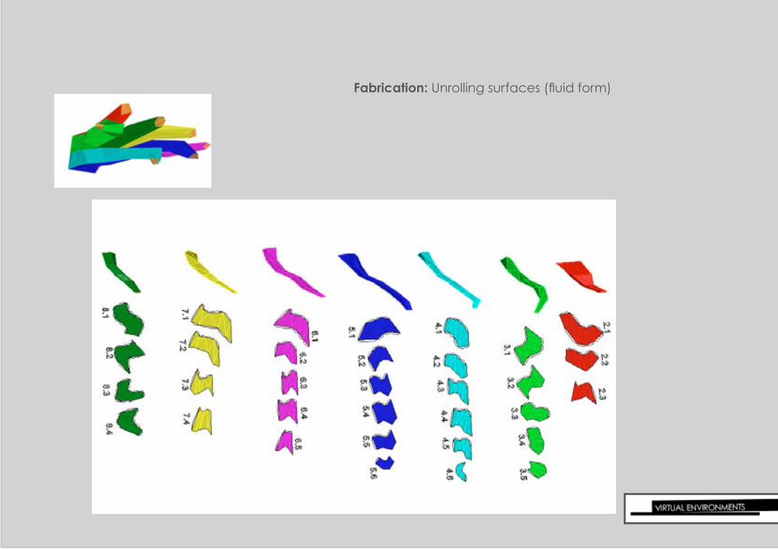
Fabrication: Unrolling surfaces (fluid form)

Fabrication: Initial prototyping
Scaling was an issue at first when unrolling the faces. I was unsure what scale I had lofted the sectional cuts of my physical model during module 2.
I had intended to submit a prototype to the fablab and construct it before deciding on how much I was required to change the size, however by the time it was eventually cut it was too late to either construct or resubmit.
During this process however I was able to print and construct a section of the rigid surface at home

Fabrication: 1:1 scale prototype
As I mentioned, my fablab submission was not able to be cut. I therefore set about creating a 1:1 scale mod-el of my lantern by exporting the sheets of unrolled panels to Illustrator and printing it on size A0 paper (80 gsm) and then using spray adhessive to bond this with 120 gsm paper.
This involved cutting and scoring the individual pieces before sticking them together using the tabs I had cre-ated.
pictures demonstrate 1:1 construction methods

Fabrication: 1:1 scale prototype
From the reslutant model I was able to discovour flaws in the panelling.
The tabs I had created were perfect, however the big open end did experience some deformation as it wasn’t as structurally sound as the closed end.
The size and weight of this section of it meant that it was sagging. From this I under-stood that either stronger ma-terials are required, or some sort of ribbing.
In addition there was a prob-lem with panel 1.7B. Pictured top right is the hole where this panel should fit, however it doesn’t.
The surface therefore requires some manipulation before a succesfull model can be cre-ated
Shown below:
Demonstrated here is the sagging expe-rienced by the large open end of the 1:1 scale model

Fabrication:1:1 scale prototype- Lighting

Reflection:
While I experienced time constraints, due to technical problems (fablab), when attempting to create a suc-cesfull model, throughout module 3 I have developed a lantern that falls in line with what I had set out to do in module 1.
Some changes must be made before I can complete the process however it is not out of reach. Looking back I am not entirely happy with the paneling of my rigid form. While I said I wanted it to be minimal, I have ended up with just standard paneling that hasn’t been diiferentiated from many other students concepts.
I am content however with the success of the fluid form. I struggled to create a sufficient design that was practi-cal, but in the end I created something that fulfilled my expectations in terms of aethsetics.
If I am able to I would still like to attempt to integrate the two forms by passing some of the ‘tenticles’ through the holes created in the rigid surface.
I believe that throughout this module I have made much more signifigant advancements than I did through mod-ule 2


