Page 1 of 22 CORK INSTITUTE OF TECHNOLOGY INSTITIÚID TEICNEOLAÍOCHTA CHORCAÍ Semester 1 Examinations 2008/09 Module Title: Advanced Structural Design Module Code: CIVL 8001 School: Building & Civil Engineering Programme Title: Bachelor of Engineering (Honours) in Structural Engineering - Award Programme Code: CSTRU_8_Y4 External Examiner(s): Mr P Anthony; Prof P O’Donoghue Internal Examiner(s): Mr M P Mannion; Mr L O’Driscoll Instructions: 1. Paper contains four questions. 2. Attempt all four questions 3. All questions carry equal marks. 4. Use separate Answer books for each Section. 5. Candidates may refer to: BSI-PP7312: - Extracts from British Standards for students of Structural Design and Approved design aids. Duration: 2 Hours Sitting: Winter 2008 Requirements for this examination: 2 desks per candidate – one for calculations, etc., and a second as a layoff table. Note to Candidates: Please check the Programme Title and the Module Title to ensure that you have received the correct examination paper. If in doubt please contact an Invigilator.
Transcript
Page 1 of 22
CORK INSTITUTE OF TECHNOLOGY INSTITIÚID TEICNEOLAÍOCHTA CHORCAÍ
Semester 1 Examinations 2008/09
Module Title: Advanced Structural Design
Module Code: CIVL 8001
School: Building & Civil Engineering Programme Title: Bachelor of Engineering (Honours) in Structural Engineering - Award Programme Code: CSTRU_8_Y4 External Examiner(s): Mr P Anthony; Prof P O’Donoghue Internal Examiner(s): Mr M P Mannion; Mr L O’Driscoll Instructions: 1. Paper contains four questions.
2. Attempt all four questions 3. All questions carry equal marks. 4. Use separate Answer books for each Section.
5. Candidates may refer to: BSI-PP7312: - Extracts from British Standards for students of Structural Design and Approved design aids.
Duration: 2 Hours Sitting: Winter 2008 Requirements for this examination: 2 desks per candidate – one for calculations, etc., and a second as a layoff table. Note to Candidates: Please check the Programme Title and the Module Title to ensure that you have received the correct examination paper. If in doubt please contact an Invigilator.
Page 2 of 22
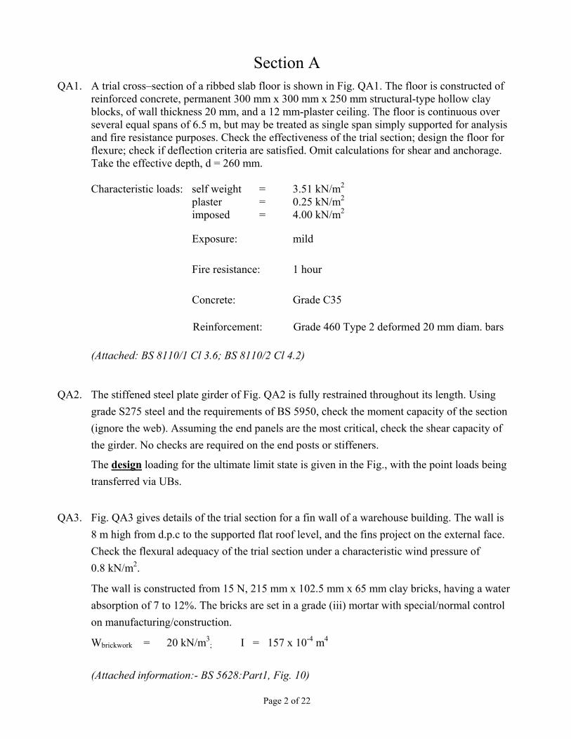
Section A QA1. A trial cross–section of a ribbed slab floor is shown in Fig. QA1. The floor is constructed of
reinforced concrete, permanent 300 mm x 300 mm x 250 mm structural-type hollow clay blocks, of wall thickness 20 mm, and a 12 mm-plaster ceiling. The floor is continuous over several equal spans of 6.5 m, but may be treated as single span simply supported for analysis and fire resistance purposes. Check the effectiveness of the trial section; design the floor for flexure; check if deflection criteria are satisfied. Omit calculations for shear and anchorage. Take the effective depth, d = 260 mm.
Reinforcement: Grade 460 Type 2 deformed 20 mm diam. bars
(Attached: BS 8110/1 Cl 3.6; BS 8110/2 Cl 4.2)
QA2. The stiffened steel plate girder of Fig. QA2 is fully restrained throughout its length. Using grade S275 steel and the requirements of BS 5950, check the moment capacity of the section (ignore the web). Assuming the end panels are the most critical, check the shear capacity of the girder. No checks are required on the end posts or stiffeners.
The design loading for the ultimate limit state is given in the Fig., with the point loads being transferred via UBs.
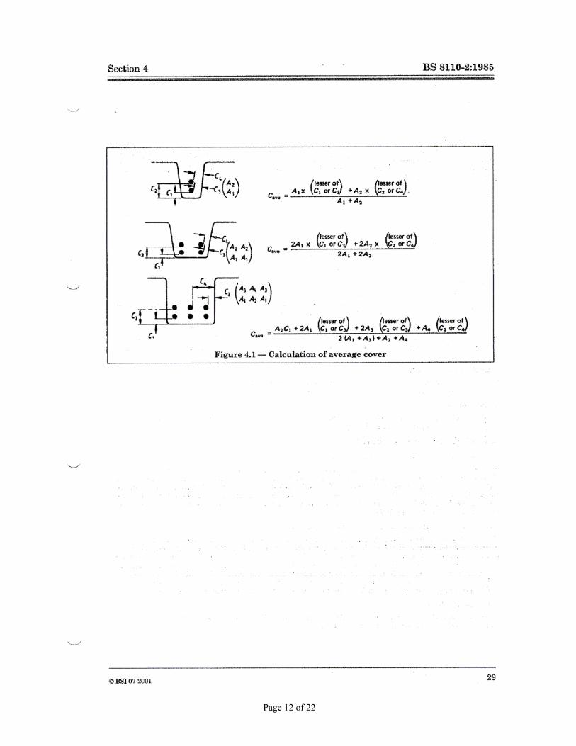
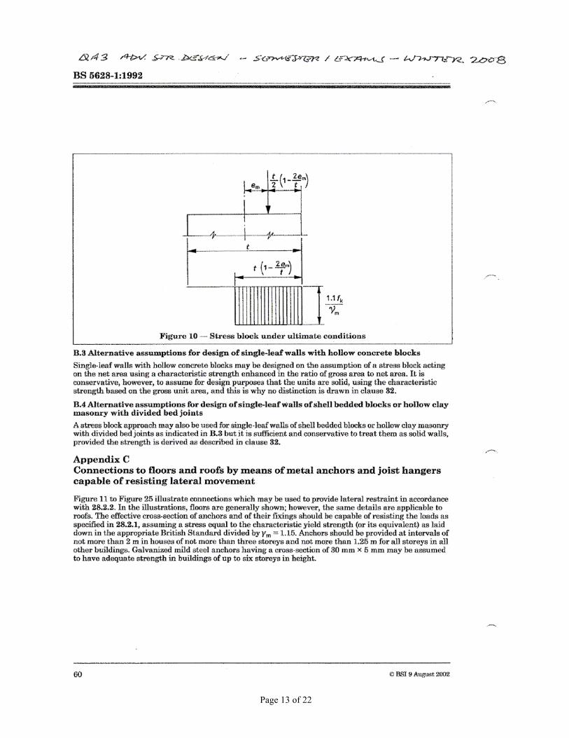
QA3. Fig. QA3 gives details of the trial section for a fin wall of a warehouse building. The wall is 8 m high from d.p.c to the supported flat roof level, and the fins project on the external face. Check the flexural adequacy of the trial section under a characteristic wind pressure of 0.8 kN/m2.
The wall is constructed from 15 N, 215 mm x 102.5 mm x 65 mm clay bricks, having a water absorption of 7 to 12%. The bricks are set in a grade (iii) mortar with special/normal control on manufacturing/construction.
Wbrickwork = 20 kN/m3; I = 157 x 10-4 m4
(Attached information:- BS 5628:Part1, Fig. 10)
Page 3 of 22
All dimensions in mm
DO NOT SCALE
Cork Institute of Technology - BEng in Structural Engineering - Stage 4
stainless steel wall ties to IS 268and Table 6of BS 5628/1 & IS 325/1
300 mm x 300 mm x 250 mm structural-type hollow clay blocks
Longitudinal section
LCCL
Page 4 of 22
Section A Attachments
Page 5 of 22
Page 6 of 22
Page 7 of 22
Page 8 of 22
Page 9 of 22
Page 10 of 22
Page 11 of 22
Page 12 of 22
Page 13 of 22
Page 14 of 22
Section B
B1(a) A covered underground reinforced concrete wastewater storage tank is required as shown in Figure C1. The tank shall have internal plan dimensions as shown. All walls are 450mm thick. The cover comprises of precast concrete slabs, with a thickness of 200mm.
Complete the following design checks:
(i) Calculate the maximum vertical moment at the base of Wall A for serviceability limit states, for tank empty, and full backfill, including maximum water table. (7 marks)
(ii) Calculate the maximum vertical moment in the Wall B for serviceability limit states, for tank full, and no backfill. (5 marks)
(iii) Calculate minimum thermal steel requirements (horizontal steel) for Wall A. (5 marks)
(iv) Using the “Deemed to satisfy” requirements in BS 8007, calculate the vertical steel required on the outside face of Wall A. (8 marks)
Figure C1
Vertical Section
10m
NB: Dimensions are internal tank dimensions ie. they do not include wall thickness
500mm
2m
3m
Water Table 4.3m
0.5m
Wal
l A
Wall B
Handrail
3m 5m
200mm
Plan view of tank
Page 15 of 22
Design information:
fcu = 35 N/mm2 fy = 460 N/mm2
αconc = 12 x 10-6 / 0 C (coefficient of thermal expansion of mature concrete)
∆T = 300C = Temperature change
Assume soil bearing capacity is adequate. Maximum design crack width = 0.2mm. The
surcharge load on surrounding ground is 10 KN / m2.
Soil Properties
Granular soil density = 18 KN/m3. Angle of repose (φ) = 300
Clearly state any design assumptions made.
The structure should not include movement joints.
Page 16 of 22
DSE4 ADVANCED STRUCTURAL DESIGN – SECTION B
Additional Information
ASSESSMENT OF CRACK WIDTHS IN FLEXURE Depth to Neutral Axis, x (elastic theory) x = αe ρ (( 1 + 2/ αe ρ)0.5- 1) d (Assume αe = 15) z = d – x/3 Steel stress fs = M/z.As ε1 = (h – x) fs / (d – x) Es ε2 = b (h – x)2 / 3 Es As (d – x) (For a limiting design surface crack of 0.2mm) εm = ε1 - ε2 w = 3 acr εm / {1 + {2 (acr – cmin) / (h –x)}} BS 8007:Appendix B:Section B.2
THERMAL AND MOISTURE CRACKING ρcrit = 0.0035 for high yield steel BS 8007: Table A.1 smax = (fct / fcb) x (φ / 2 ρ)
where:
fct / fb = 2/3 smax = maximum crack spacing ρ = Steel ratio φ = Size of each reinforcing bar