TENDER NO. MOT/05/2018-2019 PROPOSED REGENERATION OF JOMO KENYATTA PUBLIC BEACH FOR MINISTRY OF TOURISM AND WILDLIFE STATE DEPARTMENT OF TOURISM IN MOMBASA COUNTY APROXIMATE BILLS OF QUANTITIES (MAIN WORKS ESTIMATE) Planning Systems Services Ltd., Architects, P.O. Box 188 - 00606, Nairobi. Planning Project Management Ltd., Project Managers, P.O. Box 188 - 00606, Nairobi. Davson & Ward, Quantity Surveyors, Building Economists & Project Managers, P.O. Box 46611 - 00100 GPO, Nairobi. APRIL, 2019
- All the listed Equipment (10 Points) - Less than the listed items (Pro-rata
5
SUBTOTAL SECTION D
E Business Support 19
Availability of Liquid assets (5 points) and access to lines of credit or other financial resources (5
points) - (total 10 Points) 10
Proof of Financial stability (current ratio of 2:1) – (4 Points) 4 Information regarding any litigation, current or during the last five years, in which the tenderer is
involved, the parties concerned and disputed amount. If none, state so. (5 Point) 5
SUB TOTAL SECTION E
F At least 3 referees List below (attach copies of referees).
3
Three referees (3 points 3 Less or none(0) 0 SUBTOTAL SECTION F
G Completion programme for the works – 3
Realistic shortest contract period (3 Points) 3 Any other period (Pro-rata) 0 SUB TOTAL SECTION G
GRAND TOTAL 100
Cut off – 75% to qualify for financial evaluation.
STAGE 3 – FINANCIAL EVALUATION
Price comparison and checking for arithmetic errors.
RECOMMENDATION
THE LOWEST EVALUATED TENDER TO BE RECOMMENDED FOR CONSIDERATION OF
AWARD SUBJECT TO THE STATED CONDITIONS OF AWARD.
16
EVALUATION QUESTIONAIRE
A. Documents to be duly filled in accordance with instructions to tender
B.Personnel
1. Qualification and experience of key personnel proposed for administration
and execution of the Contract. Attach biographical data.
The name (and identification number) of the contract is PROPOSED REGENERATION
OF JOMO KENYATTA PUBLIC BEACH IN MOMBASA COUNTY
The Works consist of See Page 1/4 of Bill No. 1 Preliminaries & General Conditions
.
The Start Date shall be To be notified by Project Manager .
The Intended Completion Date for the whole of the Works shall be
(To be submitted with Form of Tender)
The following documents also form part of the contract:
See Clause 2.1 of the Conditions of Contract
The contractor shall submit a revised program for the Works within 14 days after the
statutory 21 days requirement for contract award.
The Site Possession Date shall be To be notified by the Project Manager
The Site is located at See Page 1/4 of Bill No. 1 – Preliminaries & General Conditions
and is defined in drawings nos.
49
The Defects Liability period is 180 days.
Other Contractors, utilities etc., to be engaged by the Employer through the
Contractor on the Site Include those for the execution of;
1. Electrical Installations
2. Plumbing, drainage and fire fighting installations
3.
The minimum insurance covers shall be;
1. The minimum cover for insurance of the Works and of Plant and Materials in
respect of the Contractor’s faulty design is KShs. 10.0 million
2. The minimum cover for loss or damage to Equipment is KShs. 10.0 million
3. The minimum for insurance of other property is KShs. 10.0 million
4. The minimum cover for personal injury or death insurance
• For the Contractor’s employees KShs. 10.0 million
• And for other people is KShs. 10.0 million
The following events shall also be Compensation Events:
1 – 4 N/A
The period between Program updates is As determined by the Project Manager
The amount to be withheld for late submission of an updated Program is
10% of certified amount
The proportion of certified payments retained is 10%.
The Price Adjustment Clause shall not apply (Clause 25)
The liquidated damages for the whole of the Works is KShs. 500,000/- per month or
part thereof.
The Performance Security shall be for the following minimum amounts equivalent as a
percentage of the Contract Price 10 percent (%)
The Completion Period for the Works is (as in Form of Tender) (weeks)
The rate of exchange for calculation of foreign currency payments is Not Applicable
The schedule of basic rates used in pricing by the Contractor is as attached -
contractor to attach].
Advance Payment shall not be granted.
The rate of exchange for calculation of foreign currency payments is Not applicable
ITEM
No.Shs. Cts.
A.
B.
Shs.
1165
State Department of Tourism,
The terms, phrases and abbreviations shall be deemed to have the
following meanings wherever used hereinafter and in all Contract
documents.
The Project Manager Planning Project Management Limited,
P.O. Box 188 - 00606,
Nairobi.
PRELIMINARIES AND GENERAL CONDITIONS
BILL NO 1
Economists,
Nairobi.
DEFINITIONS OF TERMS
Structural_Engineer' for this project shall be Mangat IB Patel Structures
Limited, Consulting Engineers, P.O. Box 48674 - 00100, Nairobi, or in
the event of his death, or ceasing to be the Structural Engineer for the
purpose of this Contract, such other person as the Employer shall
nominate for that purpose. For the purpose of the structural
engineering works, the Engineer shall be deemed vested with the duties
of and be the representative of the Architect, except in respect of
variations which involve the Contract Sum.
5 Cedar Road, Westlands,
PRELIMINARIES
NAMES OF PARTIES
P.O. Box 46611 - 00100 GPO,
Planning Systems Services Limited,
Architects,
P.O. Box 188 - 00606,
Nairobi.
Ministry of Tourism and Wildlife,
P.O Box 30027 - 00100,
Nairobi, Kenya.
The following names will be inserted in the Articles of Agreement:
The Architect
The Quantity Surveyor
The Employer
Quantity Surveyors and Building
Davson & Ward,
Davard House,
Planning House, Lower Kabete Road,
Planning House, Lower Kabete Road,
1/1
ITEM
No.Shs. Cts.
Shs.
1165
Civil Engineer_&_Geotech_Surveyor' for this project shall be Britech Ltd
P.O. Box 15130 - 00509, Nairobi, or in the event of his death, or ceasing
to be the Civil Engineer & Geotech Surveyor for the purpose of this
Contract, such other person as the Employer shall nominate for that
purpose. For the purpose of the civil engineering and geotech survey,
works, the Engineer shall be deemed vested with the duties of and be
the representative of the Architect, except in respect of variations which
involve the Contract Sum.
Landscape_Architect' for this project shall be Insite Landscape
Architects (PTY) Ltd, 117 Karim Avenue, Doringkloor, Centurion, South
Africa, 0157, or in the event of his death, or ceasing to be the
Landscape Architect for the purpose of this Contract, such other person
as the Employer shall nominate for that purpose. For the purpose of
landscaping works, the Landscaper shall be deemed vested with the
duties of and be the representative of the Architect, except in respect of
variations which involve the Contract Sum.
Transport_&_Mobility_Specialists' for this project shall be Mobility In
Chain Srl, a company duly organized and existing under the Republic of
Italy, with its principal place of business in Milan, via Ciovasso 4 - 20021
Milan, Italy, or in the event of his death, or ceasing to be the Transport &
Mobility Specialists for the purpose of this Contract, such other person
as the Employer shall nominate for that purpose. For the purpose of
the transport and mobility works, the Transport & Mobility Specialists
shall be deemed vested with the duties of and be the representative of
the Architect, except in respect of variations which involve the Contract
Sum.
Environmental_Consultant' for this project shall be Green by Choice,
P.O. Box 21212 - 00505, Nairobi, or in the event of his death, or ceasing
to be the Environmental Consultant for the purpose of this Contract,
such other person as the Employer shall nominate for that purpose.
For the purpose of the environmental works, the Consultant shall be
deemed vested with the duties of and be the representative of the
Architect, except in respect of variations which involve the Contract
Sum.
PRELIMINARIES
Mechanical and Electrical Engineer' for this project shall be Emplan
Limited P.O. Box 1746 - 00606, Nairobi, or in the event of his death, or
ceasing to be the Mechanical and Electrical Engineer for the purpose of
this Contract, such other person as the Employer shall nominate for that
purpose. For the purpose of the mechanical and electrical engineering
works, the Engineer shall be deemed vested with the duties of and be
the representative of the Architect, except in respect of variations which
involve the Contract Sum.
1/2
ITEM
No.Shs. Cts.
'Approved'
'Directed'
'Selected'
'm3'
'm2'
'm'
'mm'
'Kg.'
'No.'
'Prs.'
'K.S.'
Shs.
1165
Surveyor' for this project shall be Map Surveys (K) Ltd, P.O. Box 44902 -
00100, Nairobi, or in the event of his death, or ceasing to be the
Surveyor for the purpose of this Contract, such other person as the
Employer shall nominate for that purpose. For the purpose of
surveying works, the Surveyor shall be deemed vested with the duties of
and be the representative of the Architect, except in respect of
variations which involve the Contract Sum.
PRELIMINARIES
'As before' shall mean in all respects as earlier described in the same
or a previous Bill.
shall mean the current Kenya Standard Specification
published by the Kenya Bureau of Standards.
As described' shall mean as described in the 'Descriptions of
Materials and Workmanship' contained in the Appendices to these Bills
of Quantities.
shall mean approved by the Architect at his absolute
discretion,
shall mean Kilogramme
shall mean linear metre.
shall mean linear millimetre.
shall mean Number
shall mean Pairs,
'Contractor' shall mean the person or persons, partnership, firm or
company, whose tender for this work has been accepted, and who has
or have, signed this Contract and shall include his or their heirs,
executors, administrators, assigns, successors and duly appointed
representatives.
Works' shall mean all or any portion of the work, materials and articles,
wherever the same are being manufactured or prepared, which are to
be used in the execution of this Contract and whether the same may be
on the site or not.
shall mean directed by the Architect at his absolute
discretion.
shall mean selected by the Architect at his absolute
discretion.
shall mean cubic metre.
shall mean square metre.
1/3
ITEM
No.Shs. Cts.
A.
B.
C.
1
2
3
4
Shs.
DESCRIPTION OF SITE
Fix Only' shall mean take delivery in Mombasa (unless otherwise
stated), pay all demurrage and transport charges, load and transport to
site where necessary, unload, store, unpack, check contents against
orders and packing lists, assemble as necessary, distribute to position,
hoist and fix only.
'Do.' shall mean the whole of the preceding description except as
qualified in the description in which it occurs. Where it occurs in
descriptions of succeeding items it shall mean the same as in the first
description of the series in which it occurs except as qualified in the
description concerned. Where it occurs in brackets it shall mean the
whole of the preceding description which is contained within the
appropriate brackets.
DESCRIPTION OF THE WORKS
The works in this Contract comprise construction and completion of the
following facilities:-
Girths, depths or sizes grouped together in the Bills of Quantities item
descriptions by means of hyphenated upper and lower limits shall be
interpreted as 'exceeding' the lower limit and 'not exceeding' the upper
limit.
GROUPED SIZES
3No. Ablution blocks
Enabling works for the kiosks
The site of the proposed works is located in Bamburi, Mombasa County.
The Contractor is recommended to visit the site and will be deemed to
have satisfied himself with regard to the conditions of the site, the risk of
injury to the property adjacent to the site, or to the occupiers of such
property, the nature of the materials to be excavated and conditions
under which the works will have to be carried out, the supply of and
conditions affecting labour and the facilities for obtaining the articles or
materials referred to in these Bills of Quantities. No claim by the
Contractor for additional payment will be allowed on the ground of any
misunderstanding or misapprehension in respect of any such matter or
otherwise. Any damage caused to existing accesses and roads must be
made good as directed by and to the approval of the Architect
1No. Gateway
Demolitions and Alterations
1/4
ITEM
No.Shs. Cts.
1165
5
6
a)
b)
c)
d)
7
8
9
10
12
13
14
15
16
A.
B.
Shs.
1165
Mechanical installations
Soft landscaping and furniture
Shade areas in food market
Restoration & refurbishment of existing structures
Bill No. 13 "Schedule of rates" which must be priced by the tenderer will
be used for valuation of additional works ordered which are not part of
the measured works.
PRELIMINARIES
The scope of works described above and contained within these Bills of
Quantities is subject to amendment and change at the sole discretion of
the Architect and the Employer. The work to be undertaken may be
added to, omitted or amended to any extent.
SCOPE OF WORKS
Hard landscape areas
Stormwater drainage
Foul drainage
Electrical installations
ACCESS TO SITE
Means of access to the site shall be agreed with the Ministry of Tourism
and Wildlife State Department of Tourism and the Architect prior to the
commencement of work. The Contractor must allow here for any
temporary access roads required for the transport of all materials, plant
and the workmen necessary for the complete execution of the works,
removing same at completion and for making good and reinstating to
the entire satisfaction of the Architect all works or services disturbed at
the completion of the Contract. The Contractor must also allow for
keeping the existing Public Highways and Roads clean and for making
good all damage to the satisfaction of the Architect and Local Authority.
Refuse collection area
No adjustment of any submitted tender rates or prices, including those
for this Bill No. 1, will be permitted as a result of finalization of the scope
of works and under no circumstance will claim for resultant extra cost
etc. be accepted from the Contract.
100No. Food kiosks
Sculptures and artworks
Matatu interchange parking and driveways
Beachfront squares (2000m2)
New access road (450m long x 4m wide)
Pedestrian access way
PRELIMINARIES
1/5
ITEM
No.Shs. Cts.
C.
A.
B.
C.
D.
Shs.
1165
AREA TO BE OCCUPIED BY THE CONTRACTOR
The areas to be occupied by the Contractor for use as storage or for the
erection of workshops etc. shall be defined on the site by the Architect
and the Contractor must confine his activities to the areas so marked
and must ensure that his own and his sub‑contractors workmen do not
trespass on the adjoining property or cause inconvenience to its
occupiers.
The works are to be executed in accordance with the drawings referred
to in the Schedule of Drawings used for Bills of Quantities contained in
Appendix 'A' to these Bills of Quantities together with Contract drawings
and any drawings which may be supplied in amplification or amendment
thereof.
DRAWINGS
VALUATION OF LUMP SUM PRELIMINARY COSTS
Lump sums entered in these Bills of Quantities against any item of
Preliminaries and General Conditions will be included in appropriate
valuations according to reasonable assessment of actual costs involved
in the item. Any balance between this assessment and the actual sum
entered in the Bills of Quantities will be included in subsequent
valuations as monthly instalments over the balance of the Contract
Period.
PAYMENT FOR MATERIALS ON SITE
NOMINATED SUPPLIERS' AND SUB-CONTRACTORS' MATERIALS
All materials for incorporation in the works must be stored on or
adjacent to the site before payment is effected, unless specifically
exempted by the Architect. This is to include the materials of the
Contractor, Nominated Sub‑Contractors and Nominated Suppliers.
Nominated Sub-contract and Nominated Supply Agreements will be
finalised as soon as possible after the contract has been signed. The
Contractor will be deemed to have taken account of this in his allowance
for the provision of space for storage of Nominated Sub-Contractors'
materials and for the provision of storage facilities on or off site for
Nominated Suppliers' materials until required.
The Contractor will be deemed to have examined the drawings before
tendering and to have satisfied himself regarding their details and
regarding the nature and extent of the works and the method of
construction involved. No claims arising out of misapprehension in
these respects will be allowed. Drawings may be seen by appointment
at the offices of the Architect during normal working hours.
PRELIMINARIES
1/6
ITEM
No.Shs. Cts.
A.
B.
C.
D.
E.
F.
G.
H.
I.
J. NATIONAL INSURANCE AND PENSIONS
K.
Shs.
1165
COMPLIANCE WITH REGULATION NOTICES ETC.
The Contractor shall allow for paying all legally demandable fees, rates
or taxes including VAT (currently rated at 16%), and those for hoardings
and temporary buildings, and no adjustment of the Contract Sum will be
made in respect of such payments unless expressly stated to the
contrary in these Bills of Quantities.
The Contractor shall apply for, provide all transport necessary for, any
pay all costs and charges in connection with the Occupation Certificate
Documentation required for such Certificate(s) will be provided by the
Architect.
PRELIMINARIES
INSURANCE(S) AND SECURITIES
TOOLS, PLANT, ETC.
Provide Performance Security.
Provide Insurance for the Works.
Provide Insurance for Third Party.
Provide Insurance for Contractor's employees and loss or damage to
equipment.
The Contractor shall allow for providing all ladders, tools, plant and
transport required for the works, except in so far as may be specifically
stated otherwise herein.
The Contractor shall allow for providing for the safety, health and
welfare of workpeople and for complying with any relevant Ordinances,
Regulations or Union Agreement.
The Contractor to provide the following insurances and securities as the
Conditions of the Contract.
The Contractor shall allow for providing holidays and transport for
workpeople and for complying with any relevant Ordinances,
Regulations or Union Agreement.
SAFETY, HEALTH AND WELFARE OF WORK PEOPLE
The Contractor shall allow for making any National Hospital Insurance
Fund, National Social Security Fund payments due in respect of
workpeople.
HOLIDAYS AND TRANSPORT FOR WORKPEOPLE
Provide Bid Security.
1/7
ITEM
No.Shs. Cts.
A.
B.
C.
Shs.
1165 PRELIMINARIES
The Contractor shall allow for the protection of the whole of the existing
temporary and permanent works as well as of his own and his
Sub‑Contractor's work liable to damage, including provision of
temporary roofs, gutters, drains, etc., if necessary and shall case‑up,
cover, or in other suitable ways protect all finished work liable to injury,
to the satisfaction of the Architect until completion of the Contract.
From the beginning to the completion of the works, the same shall be
under the entire care and control of the Contractor, who shall take all
possible precautions to prevent any nuisance, inconvenience or injury to
the holders or occupiers of surrounding properties and to the public
generally, and shall at all times keep all paths and roads affected by the
works in a safe and clear state, and shall use proper precautions to
ensure the safety of all wheeled traffic and pedestrians. The Contractor
shall allow for providing all watching, lighting, barriers, covering open
trenches and protection of the works, including Sub‑Contract works, as
may be necessary for the safety of the works and for the protection of
the public and his own and Sub‑Contractors' employees.
In the event of any damage or loss occurring to the works, or to
materials or to any sewers, gullies, drains, paths, or other works on the
site in temporary possession of the Contractor for the purpose of this
Contract, either from the weather, want of proper protection, defects,
theft, insufficiency of the works, or any other cause whatsoever during
the progress of the works, or for any accident or damage to property or
persons by reason of the said works, the Contractor alone shall be
responsible and shall without extra charge, make good all damage and
pay all costs incurred.
STANDARDS LEVY AND STANDARDS ACTS
The Contractor's attention is drawn to legal notice No. 267 of 1990
which requires payment by Contractors of an annual Standards Levy
and his tender must include for all costs arising or resulting therefrom.
The Contractor's attention is drawn to Legal Notice No. 237 of October,
1971, which requires payment by the Contractor of a Training Levy on
all contracts of more than Shs. 50,000/‑ in value and his tender must
include for all costs arising or resulting therefrom. Proof of payment of
this Training Levy will be required.
Time being of the essence in this Contract, however, the Contractor
shall be deemed to have allowed for necessary overtime payments for
work people who may be called to work during the public and gazetted
holidays.
PROTECTION OF WORKS AND PERSONS
TRAINING LEVY
1/8
ITEM
No.Shs. Cts.
A.
B.
C.
D.
E.
Shs.
1165 PRELIMINARIES
Approval by the Architect of the programme shall not relieve the
Contractor of any of his obligations under the Contract.
The Contractor shall not without the Architects consent make any
material alteration to the approved programme.
PROCEDURE, TIME FOR COMPLETION
If the Architect decides that progress does not match the programme,
he may order the Contractor to revise the programme. The Contractor
shall thereafter revise the programme to show the modifications
necessary to ensure completion of the works by the Date of Practical
Completion.
If required by the Architect this chart shall be generated and up-dated by
an approved computer program.
WORKING HOURS
The working hours shall be those generally operated by good employers
in the building industry. No concrete work shall be carried out at night or
on gazetted holidays unless the Architect shall so direct. All other works
shall be executed at the discretion of the Contractor.
the Contractor shall proceed with the works in such manner and such
order as the Architect may direct.
POLICE REGULATIONS
The Contractor shall allow for complying with any relevant police
regulations.
PROGRAMME AND PROGRESS
CONTRACT SUM
This is a fixed price contract. The Contractor should therefore allow
in his rates for any anticipated price increase in the cost labour,
material, plant, fuel etc. Until completion of the works. No claim of
increase in costs will be entertained except on changes arising from
duties, taxes, levies etc.
The Contractor shall furnish to the Architect, within 14 days, for approval
and display in the site offices, a programme and progress chart devised
in such a way that the previously agreed contractually enforceable lined
programme is shown and progress can be marked up as the work
proceeds. The Contractor shall keep this chart up to date at all times.
1/9
ITEM
No.Shs. Cts.
A. BLASTING OPERATIONS
Blasting will not be allowed.
B.
Shs.
1165
Following receipt of such a notice the Contractor shall take such steps
as may be necessary, and as the Architect may approve, to remedy or
mitigate the likely delay, including revision of the programme. The
Contractor shall not be entitled to any additional payment for taking such
steps.
DAYWORKS
The Architect may, if in his opinion it is necessary or desirable, order in
writing that any additional or substituted work shall be executed on a
Daywork basis. The Contractor shall then be paid for such work in
accordance with Daywork rates and percentage additions as inserted
hereafter in these Bills of Quantities.
The Architect shall notify the Contractor if the Architect decides that the
rate of progress of the works, or any section is too slow to meet the Date
for Practical Completion and that this is not due to a circumstance for
which the Contractor is entitled to an extension of time under the
Contract.
The Contractor shall furnish to the Architect all receipts or vouchers as
may be necessary to prove the amounts paid and before ordering
materials shall submit to the Architect quotations for the same for his
approval.
In respect of all work executed on a Daywork basis the Contractor shall,
during the continuance of such work, deliver each day to the Architect a
list in duplicate of the names, occupation and time of all workmen
employed on such work and a statement also in duplicate showing the
description and quantity of all materials and plant used thereon or
therefor (other than plant which is included in the percentage addition on
net amount of wages). One copy of each list and statement will, if
correct or when agreed, be signed by the Architect and returned to the
Contractor.
At the end of each month the Contractor shall deliver to the Architect a
priced statement of the labour, material and plant (except as aforesaid)
used and the Contractor shall not be entitled to any payment unless
such lists and statements have been fully and punctually rendered.
Provided always that, if the Architect shall consider that for any reason
the sending of such list or statement by the Contractor in accordance
with the foregoing provision was impracticable, he shall nevertheless be
entitled to authorize payment for such work either as Daywork (on being
satisfied as to the time employed and plant and materials used on such
work) or at such value thereof as he shall consider fair and reasonable.
PRELIMINARIES
1/10
ITEM
No.Shs. Cts.
A.
B.
C.
D.
E.
a)
b)
Shs.
1165
LIGHTING AND POWER FOR THE WORKS
The Contractor shall allow for providing all temporary lighting and power
supplies required for the works, including Sub‑Contract works, together
with all necessary meters and distribution systems for the same and
must allow for bearing all expenses incurred and paying for all current
consumed without charge to any Sub‑Contractor. Expenses in
connection with Nominated Sub‑Contractors should be allowed for in
the attendance items under the relevant P.C. Sums.
SITE OFFICES
CROSSINGS AND TEMPORARY ROADS
The Contractor must allow for providing, forming and maintaining
necessary crossings on to the site and temporary roads as may be
required by the Architect and removing the same at completion and
making good damaged or disturbed surfaces as directed by and to the
approval of the Architect.
The Contractor shall arrange to provide telephone and Email contacts
which shall be accessible at all times. The Contractor shall pay all
charges for hire or purchase of equipment, licences, connection, rental
and calls made through these lines.
The Contractor may allow for erecting and maintaining on the site in
such positions as may be directed, adequate site offices for the use of
his own site staff and removing same at completion and making good all
surfaces disturbed. The site office shall be of adequate size and shall
have sufficient furniture to permit the Architect to hold site meetings in it.
The Contractor shall also allow for providing erecting and maintaining,
on the site where directed, an adequate office of approved construction
and finishes and with sufficient furniture for the sole use of the Clerk of
Works appointed by the Architect with sufficient space to accommodate
25 persons during site meetings.
TELEPHONE
The Contractor shall allow for providing all temporary water supplies
required for the works, including Sub‑Contract works, together with all
necessary storage tanks, meters and distribution systems for the same
and must allow for bearing all expenses incurred and paying for all
water consumed without charge to any Sub‑Contractor. Expenses in
connection with Nominated Sub‑Contractors should be allowed for in
the attendance items under the relevant P.C. Sums.
WATER FOR THE WORKS
PRELIMINARIES
1/11
ITEM
No.Shs. Cts.
c)
d)
A.
B.
C.
D.
Shs.
1165
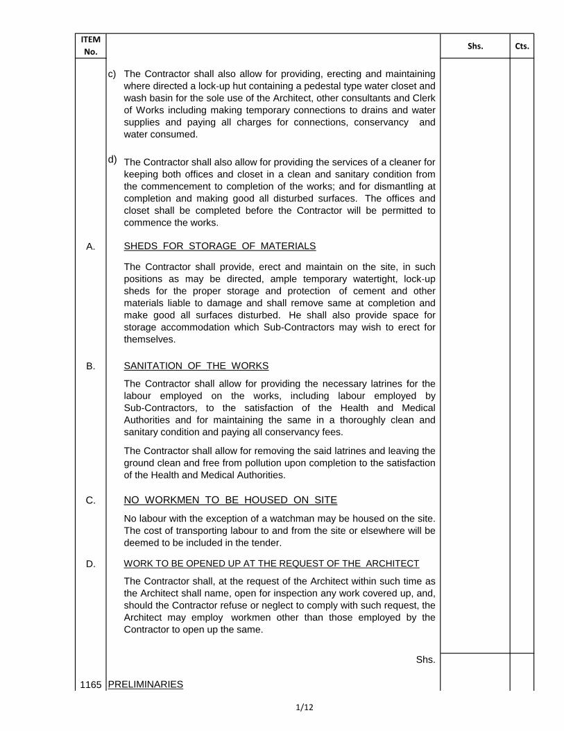
The Contractor shall, at the request of the Architect within such time as
the Architect shall name, open for inspection any work covered up, and,
should the Contractor refuse or neglect to comply with such request, the
Architect may employ workmen other than those employed by the
Contractor to open up the same.
PRELIMINARIES
The Contractor shall allow for removing the said latrines and leaving the
ground clean and free from pollution upon completion to the satisfaction
of the Health and Medical Authorities.
No labour with the exception of a watchman may be housed on the site.
The cost of transporting labour to and from the site or elsewhere will be
deemed to be included in the tender.
NO WORKMEN TO BE HOUSED ON SITE
The Contractor shall allow for providing the necessary latrines for the
labour employed on the works, including labour employed by
Sub‑Contractors, to the satisfaction of the Health and Medical
Authorities and for maintaining the same in a thoroughly clean and
sanitary condition and paying all conservancy fees.
SANITATION OF THE WORKS
The Contractor shall provide, erect and maintain on the site, in such
positions as may be directed, ample temporary watertight, lock‑up
sheds for the proper storage and protection of cement and other
materials liable to damage and shall remove same at completion and
make good all surfaces disturbed. He shall also provide space for
storage accommodation which Sub‑Contractors may wish to erect for
themselves.
SHEDS FOR STORAGE OF MATERIALS
The Contractor shall also allow for providing, erecting and maintaining
where directed a lock‑up hut containing a pedestal type water closet and
wash basin for the sole use of the Architect, other consultants and Clerk
of Works including making temporary connections to drains and water
supplies and paying all charges for connections, conservancy and
water consumed.
WORK TO BE OPENED UP AT THE REQUEST OF THE ARCHITECT
The Contractor shall also allow for providing the services of a cleaner for
keeping both offices and closet in a clean and sanitary condition from
the commencement to completion of the works; and for dismantling at
completion and making good all disturbed surfaces. The offices and
closet shall be completed before the Contractor will be permitted to
commence the works.
1/12
ITEM
No.Shs. Cts.
A.
B.
Shs.
1165 PRELIMINARIES
The Contractor shall allow for providing, erecting and dismantling all
general scaffolding required for the works. The Contractor must allow
here or in his rates for providing all special scaffolding required by his
Sub‑Contractors, other than Nominated Sub‑Contractors carrying out
works for which P.C. Sums are included in these Bills. Where the
Contractor is required to provide special scaffolding for these latter
Sub‑Contractors, an item is included for pricing under the relevant P.C.
Sum.
The Contractor shall allow for thoroughly maintaining the hoarding and
gates throughout the Contract and clearing away and making good
disturbed ground on completion. All materials arising will remain the
property of the Contractor and he should allow credit against this
accordingly.
The Contractor shall allow for providing and clearing away on
completion such hoarding, fencing, gates etc. as may be required for the
security of the site, and as instructed by the Architect to prevent access
to the site by the public. The exact location and type of these items are
to be agreed with the Architect and negotiated with the local Authority by
the Contractor who will also be responsible for paying any fees or taxes
to the Local Authority in respect of the hoarding, fencing or gates and
providing any drawings necessary for approval.
If the said work has been covered up in contravention of the Architect's
instructions, or if, on being opened up, it be found not in accordance
with the drawings or Bills of Quantities or the instructions of the
Architect, the expenses of opening and covering it up again whether
done by the Contractor or by the Architect, shall be borne by and be
recoverable from the Contractor or may be deducted from any monies
due to the Contractor. If the work has not been covered up in
contravention of such instructions and be found in accordance with the
said drawings and Bills of Quantities, then the expenses aforesaid shall
be borne by the Employer, and be added to the Contract Sum; provided
always that, in the case of foundations or of any other urgent work so
opened up and requiring immediate attention, the Architect shall,
within a reasonable time after the work has been opened, make or
cause to be made the inspection thereof, and at the expiration of such
time, if such inspection shall not have been made the Contractor may
cover up the same and shall not be required to open it up again for
inspection except at the expense of the Employer.
SCAFFOLDING
HOARDING
1/13
ITEM
No.Shs. Cts.
A.
B.
C.
D.
E.
Shs.
1165
HOISTING
The Contractor must allow for providing, erecting and maintaining a site
signboard, the size, type of construction and lettering of which shall be
to the Architect's design. The names of the Consultants are to be in
lettering 50mm high. The board is to be fixed in an elevated position on
the site where indicated by the Architect. On completion of the works,
the notice board shall be removed and making good shall be carried out
as necessary.
REMOVAL OF PLANT, RUBBISH ETC.
The Contractor shall allow for all costs related to hoisting materials for
fixing at any level within the limits shown on the drawings or included in
the general description of the works.
SIGNBOARD
TRADE NAMES
DEDUCTION FROM MONEY DUE TO THE CONTRACTOR
PRELIMINARIES
The Contractor must allow for removing and clearing away all plant,
rubbish and unused materials, and leaving the whole of the site of the
works in a clean and tidy state at completion to the satisfaction of the
Architect. He must also allow for removing all rubbish and dirt from the
site as it accumulates during the performance of the Contract.
The Architect shall be entitled to deduct any monies which the
Contractor shall be liable to pay under the Contract to the Employer
from any sum which may become payable to the Contractor hereunder
and the Architect in issuing his Certificates as provided in Clause 34 of
the Schedule of Conditions shall have regard to any sum so chargeable
to the Contractor. Provided always that this provision shall not affect any
other remedy by action at law or otherwise to which the Employer may
be entitled for the recovery of such monies.
Where trade names or manufacturers' catalogue numbers are
mentioned in these Bills of Quantities, the reference is intended as a
guide to the type of article or quality of materials required. The
Contractor may use any article or material equal in type or quality to
those herein described subject to the prior approval of the Architect and
at his absolute discretion. The onus of proof as to equivalent quality will
rest with the Contractor, whose tender will be deemed to include for the
makes described herein.
1/14
ITEM
No.Shs. Cts.
A.
B. APPROVED SUB‑CONTRACTORS
C.
D. EXISTING PROPERTY
E.
F.
Shs.
1165
The Contractor shall take every precaution to avoid damage to all
existing property including buildings on and adjacent to the site, roads,
cables, drains and other services and he will be held responsible for all
damage arising from the execution of this Contract to the
aforementioned and he shall make good all such damage where
directed at his own expense to the satisfaction of the Architect.
DISPOSAL OF WATER
Allow for keeping the works free from all water, including spring and
running water, by pumping or other means as required.
MAINTAINING SIDES OF EXCAVATIONS
WORKS TO BE DELIVERED UP CLEAN
PRELIMINARIES
Allow for maintaining the sides of all excavations by planking and
strutting or other means as required. Additional works caused by the
collapse of excavations through inadequate planking and strutting (e.g.
re-routing of adjacent drain runs) will be at the Contractor’s expense.
Where in these Bills of Quantities work is described to be executed
by an approved Sub‑Contractor the firms appointed will be treated as
Sub‑Contractors employed by the Contractor and not as Nominated
Sub‑Contractors. The unit prices for such work must, therefore, include
not only the Sub‑Contractor's charges but also the Contractors'
overheads, profits and attendance. Such firms where not prequalified
shall be classified on the Ministry of Works lists as suitable to undertake
class 'A' works.
APPROVAL OF ARCHITECT FOR EMPLOYMENT OF SUB-
CONTRACTORS
The Contractor will be required to obtain the approval of the
Architect/Engineer in writing before Employing any of his own (i.e. not
nominated) Sub‑Contractors for any portion of the work.
On completion of the Contract, the site and the works shall be cleared of
all plant, scaffolding, rubbish and unused materials and shall be
delivered up clean and in perfect condition in every respect to the
satisfaction of the Architect. Particular attention is to be paid to leaving
all windows and floors clean and removing all paint and cement stains.
1/15
ITEM
No.Shs. Cts.
A.
B.
C.
Rate
No. 15
No. 15
No. 15
No. 15
No. 15
No. 15
Shs.
1165
TESTING
Allow for all expenses in connection with the testing of materials as
specified hereunder including the supply and preparation of materials to
be tested, the cost of materials and their packing and conveyance to the
nearest approved Testing Laboratory, laboratory charges, etc. The
following items of tests will be measured according to the number of
tests actually called for by the Architect but unsuccessful tests will not
be included in the remeasurement.
Allow for destroying any white ants' nests found in the vicinity of the
buildings, destroying Queen Ants, depositing cyanide lumps in holes
and tunnels and filling with hardcore and murram well rammed and
sealed.
Testing of concrete or stone blocks of
various strengths in accordance with British
Standard Specification (one test comprising
six blocks)
Water Test (4.5 litres)
PRELIMINARIES
The contractor shall take and hand over to the Architect at approved
intervals site progress photographs in a format to be directed by the
Architect.
SITE PHOTOGRAPHS
Reinforcement test (1m of mild steel rod or
high tensile steel bar of various sizes)
Concrete Test (One test comprising three
cubes as described hereinafter)
Allow for executing the following tests as detailed in the
Appendices to these Bills of Quantities (PROVISIONAL)
WHITE ANTS
Aggregate Test (0.028m3)
Sand Test (0.028m3)
1/16
ITEM
No.Shs. Cts.
A.
Shs.
1165
APPENDICES
The Appendices to the Bills of Quantities shall be regarded for Contract
purposes as part of the Bills and shall be read and construed with the
appropriate sections of the Bills as if contained therein.
The Contractor shall allow for all other testing of materials, apart from
the above, required by the Appendices of the Bills of Quantities and he
shall be responsible for all expenses incurred in completing such tests
including costs of materials and labour, equipment, transport and
charges of testing authority, etc.
PRELIMINARIES
1/17
ITEM
No.Shs. Cts.
1/1
1/2
1/3
1/4
1/5
1/6
1/7
1/8
1/9
1/10
1/11
1/12
1/13
1/14
1/15
1/16
1/17
Shs.
1165
" " " " “
" " " " “
" " " " “
PRELIMINARIES
TOTAL AMOUNT OF BILL NO. 1
CARRIED TO FINAL SUMMARY
" " " " “
" " " " “
" " " " “
" " " " “
" " " " “
" " " " “
" " " " “
" " " " “
" " " " “
" " " " “
" " " " “
" " " " “
BILL NO. 1
PRELIMINARIES AND GENERAL CONDITIONS
COLLECTION
Brought forward from page No.
" " " " “
1/18
ITEM
No.DESCRIPTION UNIT QUANTITY RATE Shs./Cts.
BILL NO. 2
GATEWAY
(ALL PROVISIONAL)
ELEMENT A
SUBSTRUCTURES
A. Allow for planking and strutting to sides of
excavations. Item
B. Allow for keeping excavations free from all
spring and running water Item
C. Excavate oversite to remove vegetable soil
average 150mm deep and cart away. m2 77
D. Excavate oversite to reduce levels commencing
at stripped site level and not execeeding 1.50m
deep. m3 74
E. Excavate foundation trench commencing at
reduced level and not exceeding 1.50m deep. m3 33
F. Do. but 1.50-3.00m deep m3 11
G. Do. but column base m3 23
H. Do. but 1.50-3.00m deep m3 8
I. Extra over excavation for excavating in coral
rock. m3 74
J. Return, fill in and ram selected excavated
material around foundations m3 48
K. Remove surplus excavated material from site m3 26
Selected hardcore
L. Filling in making up levels under floors, spread,
levelled, well rammed and consolidated in
150mm layers m3 110
M. 300mm Bed spread, levelled, well rammed and
consolidated and blinded with 50mm thick
murram, quarry dust or sand to receive damp
proof membrane (measured separately) m2 48
N. Approved insecticide treatment m2 59
Shs.
1165 GATEWAY
SUBSTRUCTURES
2/ 1
ITEM
No.DESCRIPTION UNIT QUANTITY RATE Shs./Cts.
A. 1000 Gauge approved polythene sheeting laid on
blinded hardcore (measured separately) as damp
proof membrane with welted laps (measured net-
no allowance made for laps) m2 59
Plain concrete (1:3:6)
B. 50mm blinding under foundations. m2 23
C. Do. but column bases. m2 17
Vibrated reinforced concrete (Class 25)
D. Foundations. m3 6
E. Column bases m3 5
F. Columns m3 2
G. 150mm Bed laid on damp proof membrane
(measured separately) in bays not exceeding 50
square metres including formwork to edge of
bays. m2 59
Ribbed steel bar reinforcement to B.S 4461 and
K.S. ISO 6935-2:2007
H. Assorted bar reinforcement sizes in foundations Kg. 600
I. Do. (column bases) Kg. 450
J. Do. (columns) Kg. 180
K. Steel wire fabric mesh reinforcement to B.S.
4483 Ref. A 142 and K.S. 02-18:1976 in
concrete bed (measured net, no allowance made
for minimum 225mm laps ) including tying and
supporting as required. m2 88
Shs.
1165 GATEWAY
SUBSTRUCTURES
2/ 2
ITEM
No.DESCRIPTION UNIT QUANTITY RATE Shs./Cts.
Sawn formwork
A. Sides of foundations. m2 18
B. Sides of column bases m2 14
C. Sides of columns m2 15
D. Edge of bed 150-225mm high. m 54
E. No. 16 B.W.G Hoop iron fixing clamp 25mm
wide x 450mm girth once bent and tucked to
inner face of formwork, one end cast into
concrete and the other end afterwards
straightened and built into joints of walling. No. 132
F. 200mm Approved load bearing (7N/mm2)
concrete block walling in cement motar (1:3). m2 80
G. 100mm Thick smooth dressed zero jointed cut
coral cladding on rendered plinths bedded and
jointed on and including 15mm cement and sand
(1:3) backing and including all necessary ties
and finished with brush applied protective
silicone sealant. m2 30
H. Approved plaster render on plinths finished
smooth with a steel trowel. m2 18
Shs.
ELEMENT A
SUBSTRUCTURES
COLLECTION
Brought forward from Page No. 2/1
" " " " " 2/2
" " " " " 2/3
TOTAL AMOUNT OF ELEMENT A
CARRIED TO SUMMARY AT END OF BILL
NO. 2 Shs.
1165 GATEWAY
SUBSTRUCTURES
COLLECTION
2/ 3
ITEM
No.DESCRIPTION UNIT QUANTITY RATE Shs./Cts.
ELEMENT B
FRAME
Vibrated reinforced concrete (class 25)
A. Columns. m3 3
B. Beams. m3 15
C. 75mm Projecting moulding brackets m2 12
D. 150mm Suspended slab m2 59
E. Extra over 200mm bed for thicknessing m2 9
F. 200mm Wide x 75mm thick decorative moulding m 44
G. 100mm Wide x 75mm thick decorative moulding m 63
Ribbed steel bar reinforcement to B.S 4461 and
K.S. ISO 6935-2:2007
H. Assorted bar reinforcement sizes to columns Kg. 360
I. Do. (beams) Kg. 1,500
I. Do. (projecting moulding brackets) Kg. 173
J. Do. (Suspended slabs) Kg. 608
Sawn formwork
K. Sides of columns. m2 45
L. Sides and soffits of beams. m2 147
M. Sides and soffits of projecting moulded bracket. m2 24
N. Soffits of suspended slab m2 59
O. Sides and soffits of decorative moulding 75 -
150mm high. m 95
P. Sides and soffits of decorative moulding 150 -
225mm high. m 65
Q. Edge of suspended slab 225 - 300 mm high m 54
TOTAL AMOUNT OF ELEMENT B
CARRIED TO SUMMARY AT END OF BILL
NO. 2 Shs.
1165 GATE WAY
FRAME
COLLECTION
2/ 4
ITEM
No.DESCRIPTION UNIT QUANTITY RATE Shs./Cts.
ELEMENT C
EXTERNAL WALLS
Precast concrete (class 25) bedded, jointed and
pointed in gauged mortar
A. 300 x 250mm Lintol reinforced with and
including three 10mm ribbed steel bars hooked
at ends m 27
B. 600 x 450mm Crenelations moulded to approval
on precast coping (measured separately). No. 6
C. 350 x 50mm Coping twice throated and
weathered and reinforced as necessary for
handling. m 51
D. 150 x 150mm Decorative opening in 250mm
masonry wall with and including finishing to
approval. No. 18
E. 200mm Solid concrete block walling in gauged
mortar m2 107
F. No. 16 B.W.G Hoop iron fixing clamp 25mm
wide x 450mm girth as before. No. 324
Pluvex No. 1 or other equal and approved
horizontal bitumen damp proof course to B.S.
743 (measured net - no allowance made for
laps).
G. 200mm Wide under walling. m 24
H. 200mm Wide under coping. m 77
TOTAL AMOUNT OF ELEMENT C
CARRIED TO SUMMARY AT END OF BILL
NO. 2 Shs.
1165 GATEWAY
EXTERNAL WALLS
COLLECTION
2/ 5
ITEM
No.DESCRIPTION UNIT QUANTITY RATE Shs./Cts.
ELEMENT D
ROOF FINISHES AND RAINWATER
DISPOSAL
Cement and sand (1:3) beds and backings
A. 40mm (Avarage) lightweight screed laid to falls
and crossfalls on concrete flat roof finished to
receive waterproofing membrane (measured
separately). m2 48
B. 15mm Do. but on parapet wall sides. m2 15
C. 50 x 50mm Triangular fillet. m 48
Note:- A ten year guarantee against defects will
be required for the following flat roof
waterproofing.
4mm A.P.P. or other equal and approved
waterproofing membrane laid on concrete flat
roof in accordance with the manufacturers
specifications to be executed by an approved
Sub-Contractor.
D. Finish to flat roof. m2 72
E. Do. but laid vertically on parapet wall sides. m2 23
F. Turn edge of rubber membrane into and
including groove in wall and pointed in gauged
mortar. m 72
G. 100mm Diameter 'Fullbora' rainwater outlet
from East African Foundry or other equal and
approved and fixing in concrete slab including
jointing to down pipe (measured separately)No. 5
H. Precast concrete roof pergola (class 25) bedded,
jointed and pointed in gauged mortar m2 26
Shs.
1165 GATEWAY
ROOF
2/ 6
ITEM
No.DESCRIPTION UNIT QUANTITY RATE Shs./Cts.
A. 200 x 200 x 20mm Mitchell Cotts (Kenya) Ltd
or other equal and approved precast concrete
interlocking roofing tiles bedded, jointed and
pointed in cement screed on APP waterproofing
membrane (measured separately). m2 108
B. Do. but skirting finish. m 108
C. Extra over do. for return on 50 x 50mm
triangular fillet. m 108
D. Cut and fit interlocking tiles around 100mm
diameter rainwater outlet No. 7
PVC rainwater pipes and fittings to B.S. 4514
E. 100mm Diameter down pipe fixed to masonry or
concrete with and including approved brackets.m 27
F. Extra for shoe No 7
G. Extra for bend No 7
Shs.
ELEMENT D
ROOF FINISHES AND RAINWATER
DISPOSAL
COLLECTION
Brought forward from Page No. 2/6
" " " " " 2/7
TOTAL AMOUNT OF ELEMENT D
CARRIED TO SUMMARY AT END OF BILL
NO. 2 Shs.
1165 GATEWAY
ROOF FINISHES
COLLECTION
2/ 7
ITEM
No.DESCRIPTION UNIT QUANTITY RATE Shs./Cts.
ELEMENT E
EXTERNAL WALL FINISHES
A. 15mm cement, lime and river sand (1:2:9) Lamu
plaster on walls finished smooth with a wood
float. m2 48
B. Do. (columns, moulded brackets and beams
surfaces) m2 117
C. Do. (moulded concrete surfaces) m 160
D. 300mm Wide x 50mm thick Swahili decorative
plaster as 'Vidaka' to approval. m 44
E. 250mm Do. m 114
F. 100 x 100mm square decorated recessed plaster
to approval. m 45
The following work is to be executed by an
approved Sub-Contractor.
G. Prepare and apply one undercoat and two
finishing coats of 'Jotun Paints' or other equal
and approved Marine external quality paint on
rendered walls externally. m2 72
H. Do. (columns, moulded brackets and beams
surfaces) m2 176
I. Do. but surfaces not exceeding 100mm girth
(moulded concrete surfaces) m 240
J. Do. but surfaces 200 -300mm girth (Swahili
decorated plastered areas) m 171
K. 100mm Thick smooth dressed zero jointed cut-
coral cladding on rendered wall bedded and
jointed on and including 15mm cement and sand
(1:3) backing including all necessary ties and
finished with brush applied protective silicone
sealant. m2 59
TOTAL AMOUNT OF ELEMENT E
CARRIED TO SUMMARY AT END OF BILL
NO. 2 Shs.
1165 GATEWAY
EXTERNAL WALL FINISHES
COLLECTION
2/ 8
ITEM
No.DESCRIPTION UNIT QUANTITY RATE Shs./Cts.
ELEMENT F
INTERNAL WALL FINISHES
A. 12mm Two coat internal lime plaster on walls
finished smooth with a steel trowel. m2 156
B. 100mm Wide x 25mm thick plain cement and
sand (1:3) plaster strip to approval. m 114
C. Prepare and apply one undercoat and two
finishing coats of 'Jotun Paints' or other equal
and approved Marine quality paint on
plastered walls internally to be executed by an
approved Sub-Contractor. m2 156
D. Do. but surfaces not exceeding 100mm girth
(Gateway opening) m 114
TOTAL AMOUNT OF ELEMENT F
CARRIED TO SUMMARY AT END OF BILL
NO. 2 Shs.
1165 GATEWAY
INTERNAL WALL FINISHES
COLLECTION
2/ 9
ITEM
No.DESCRIPTION UNIT QUANTITY RATE Shs./Cts.
ELEMENT G
FLOOR FINISHES
Cement and sand (1:3)
A. 40mm Paving laid on concrete and trowelled
hard and smooth and polished with and
including yellow ochre additive to the entire
satisfaction of the Architect. m2 56
TOTAL AMOUNT OF ELEMENT G
CARRIED TO SUMMARY AT END OF BILL
NO. 2 Shs.
1165 GATEWAY
FLOOR FINISHES
COLLECTION
2/ 10
ITEM
No.DESCRIPTION UNIT QUANTITY RATE Shs./Cts.
ELEMENT H
CEILING FINISHES
A 12mm Two coat internal lime plaster (cement
lime and riversand 1:2:9) on concrete soffits
finished smooth with a steel trowel. m2 50
The whole of the following work is to be
executed by an approved Sub-Contractor.
B. Prepare and apply one undercoat and two
finishing coats of 'Jotun Paints' or other equal
and approved Marine quality paint on soffits of
plastered suspended slab. m2 50
TOTAL AMOUNT OF ELEMENT H
CARRIED TO SUMMARY AT END OF BILL
NO. 2 Shs.
1165 GATEWAY
CEILING FINISHES
COLLECTION
2/ 11
ITEM
No.DESCRIPTION UNIT QUANTITY RATE Shs./Cts.
ELEMENT I
BUILDER'S WORK IN CONNECTION WITH
SPECIALIST SERVICES
Electrical Installation
Cut away for and make good after electrician
installing concealed conduit system to the
following points including cutting or leaving
holes, notches, mortices, sinking in both the
structure and its coverings and make good to
them.
A. Lighting points and associated switch points No. 15
TOTAL AMOUNT OF ELEMENT I
CARRIED TO SUMMARY AT END OF BILL
NO. 2 Shs.
1165 GATEWAY
B.W.I.C.
COLLECTION
2/ 12
ITEM
No.DESCRIPTION UNIT QUANTITY RATE Shs./Cts.
ELEMENT J
PAVED AREAS
A. Excavate over site to reduce levels commencing
at existing ground level and not exceeding 1.50m
deep. m3 153
B. Extra over excavation for excavating in coral
rock. m3 15
C. Remove surplus excavated material from site. m3 153
D. 300mm Bed of hand packed and compacted
stone base well rammed and consolidated in
150mm layers. m2 511
E. Telvar 'W' or other equal and approved weed
killer under paving. m2 511
F. 50mm (Average) sand bed blinding spread and
well compacted to falls and crossfalls and
cambers and finished to receive stone paving
(measured separately). m2 511
G. 60mm Thick medium duty 'Bamburi'/Blox or
other equal and approved precast concrete
cobble paver blocks in approved pattern laid on
sand bed (measured separately) to falls,
crossfalls, and cambers including necessary
compaction. m2 113
H. Do. but in colour charcoal topping. m2 142
I. 60mm Thick medium duty 'Bamburi'/'Blox' or
other equal and approved precast concrete quad
paver blocks in colour red topping in approved
pattern laid on sand bed (measured separately)
to falls, crossfalls and cambers including
necessary compaction. m2 256
Shs.
1165 GATEWAY
PAVED AREAS
2/ 13
ITEM
No.DESCRIPTION UNIT QUANTITY RATE Shs./Cts.
A. 125 x 250mm Precast concrete (Class 20) kerb
with one chamfered edge finished fair on all
exposed surfaces bedded, jointed and pointed in
cement mortar (1:3) on and including 325 x
100mm plain concrete (1:3:6) foundation
haunched up on one side including all necessary
excavation, formwork and soil disposal. m 101
B. 125 x 100mm Precast concrete (Class 20)
channel finished fair on all exposed surfaces
bedded, jointed and pointed in cement mortar
(1:3) on and including 375 x 100mm plain
concrete (1:3:6) foundation haunched up on one
side including all necessary excavation,
formwork and soil disposal. m 101
Shs.
ELEMENT H
PAVED AREAS
COLLECTION
Brought forward from Page No. 2/13
" " " " " 2/14
TOTAL AMOUNT FOR ELEMENT J
CARRIED TO SUMARY AT END OF BILL
NO 2 Shs.
1165 GATEWAY
PAVED AREAS
COLLECTION
2/ 14
ITEM
No. Shs. Cts.
Element Page No.
A. 2/3
B 2/4
C 2/5
D 2/7
E. 2/8
F. 2/9
G. 2/10
H. 2/11
I.
2/12
J. Paved Areas 2/14
SHS.
1165
Ceiling Finishes
BILL NO. 2
Internal Wall Finishes
External Wall Finishes
Builder Work in Connection with Specialist
Services
SUMMARY
TOTAL AMOUNT OF BILL NO. 2 CARRIED TO FINAL
SUMMARY.
Floor Finishes
Frame
External and Internal Walls
Roof Finishes and Rainwater Disposal
Substructures
BILL NO. 2
GATEWAY
SUMMARY
Title.
(ALL PROVISIONAL)
2/15
ITEM
No.DESCRIPTION UNIT QUANTITY RATE Shs./Cts.
BILL NO. 3
3NO. NEW ABLUTION BLOCKS
(ALL PROVISIONAL)
Note: Quantities are measured for one ablution
block only.
ELEMENT A
SUBSTRUCTURES
A. Allow for planking and strutting to sides of
excavations. Item
B. Allow for keeping excavations free from all
spring and running water. Item
C. Excavate over site to remove vegetable soil
average 150mm deep and cart away. m2 96
D. Excavate oversite to reduce levels commencing at
stripped site level and not execeeding 1.50m
deep. m3 48
E. Excavate foundation trench commencing at
reduced level and not exceeding 1.50m deep. m3 53
F. Extra over excavation for excavating in coral
rock. m3 101
G. Return fill and ram selected excavated material
around foundations. m3 25
H. Remove surplus excavated material from site m3 29
Selected hardcore
I. Filling in making up levels under floors, spread,
levelled, well rammed and consolidated in
150mm layers m3 77
J. 300mm Bed spread, levelled, well rammed and
consolidated and blinded with 50mm thick
murram, quarry dust or sand to receive damp
proof membrane (measured separately) m2 85
K. Approved insecticide treatment. m2 85
Shs.
1165 3NO. NEW ABLUTION BLOCKS
SUBSTRUCTURES
3/ 1
ITEM
No.DESCRIPTION UNIT QUANTITY RATE Shs./Cts.
A. 1000 Gauge 'Diothene' or other equal and
approved polythene sheeting as damp proof
membrane laid on blinded hardcore (measured
separately) with welted laps (measured net-no
allowance made for laps).m2 85
Plain Concrete (Class 15)
B. 50mm Blinding under foundations. m2 42
Vibrated reinforced concrete (Class 25)
C. Foundations m3 8
D. Columns m3 1
E. 150mm Bed laid on damp proof membrane
(measured separately) in bays not exceeding 50
square metre including formwork to edge of bays.
m2 85
F. Extra over 150mm bed for thicknessing to a total
of 200mm thick x 450mm average wider under
100mm walling including hand packing hardcore
to two sloping sides and all additional binding
and steel fabric mesh reinforcementm 22
Ribbed bar steel reinforcement as before.
G. Assorted bar reinforcement bars in foundations.
Kg. 422
H. Do. (columns) Kg. 100
I. Steel wire fabric mesh reinforcement to B.S.
4483 Ref: A 193 and K.S. 02 - 18: 1976 in
concrete bed (measeured net, no allowance made
for minimum 225mm laps) including tying and
supporting as required. m2 85
Sawn formwork
J. Sides of foundations. m2 28
Shs.
1165 3NO. NEW ABLUTION BLOCKS
SUBSTRUCTURES3/ 2
ITEM
No.DESCRIPTION UNIT QUANTITY RATE Shs./Cts.
A. Sides of column m2 7
B. Edge of bed 75- 150mm high. m 57
C. 200mm Approved load bearing (7N/mm2)
concrete block walling in cement mortar (1:3). m2 91
D. 100mm Thick smooth dressed zero jointed cut-
coral cladding on rendered surfaces bedded and
jointed on and including 15mm cement and sand
(1:3) backing including all necessary ties and
finished with brush applied protective silicone
sealant. m2 12
Shs.
ELEMENT A
SUBSTRUCTURES
COLLECTION
Brought forward from Page No. 3/1
" " " " " 3/2
" " " " " 3/3
TOTAL AMOUNT FOR ELEMENT A
CARRIED TO SUMMARY AT THE END OF
BILL NO. 3 Shs.
1165 3NO. NEW ABLUTION BLOCKS
SUBSTRUCTURES
COLLECTION
3/ 3
ITEM
No.DESCRIPTION UNIT QUANTITY RATE Shs./Cts.
ELEMENT B
FRAME
Vibrated reinforced concrete (class 25)
A. Beams. m3 5
B. 150mm Suspended roof slab m2 59
Ribbed bar steel reinforcement as before
C. Assorted bar reinforcement sizes in beams Kg. 515
D. Do. (suspended slab). Kg. 622
Sawn formwork
E. Sides and soffits of beams. m2 62
F. Soffit of suspended slab. m2 59
G. Edge of suspended slab 75-150mm high m 54
TOTAL AMOUNT FOR ELEMENT B
CARRIED TO SUMMARY AT THE END OF
BILL NO. 3 Shs.
1165 3NO. NEW ABLUTION BLOCKS
FRAME
COLLECTION
3/ 4
ITEM
No.DESCRIPTION UNIT QUANTITY RATE Shs./Cts.
ELEMENT C
EXTERNAL AND INTERNAL WALLS
Precast concrete (class 25) bedded, jointed and
pointed in gauged mortar.
A. 350 x 70mm Coping twice throated and once
weathered and reinforced as necessary for
handling and finished fair on all exposed
surfaces.m 54
B. 200 x 200mm Lintol reinforced with and
including three 100mm ribbed steel bars hooked
at ends. m 1
C. Approved Swahili decorated concrete louvre
panels. m2 26
Solid concrete block walling in gauged mortar
D. 100mm Thick internal walling, reinforced. m2 31
E. 200mm Thick internal walling. m2 12
F. Do. (external walling). m2 81
G. Do. (parapet walling). m2 69
H. Pluvex No. 1 or other equal and approved
horizontal bitumen damp proof course to B.S.
743 (measured net - no allowance made for laps)
I. 200mm Wide under walling. m 52
J 100mm Wide under walling. m 16
K 200mm wide under coping m 54
TOTAL AMOUNT FOR ELEMENT C
CARRIED TO SUMMARY AT THE END OF
BILL NO. 3 Shs.
1165 3NO. NEW ABLUTION BLOCKS
EXTERNAL AND INTERNAL WALLS
COLLECTION
3/ 5
ITEM
No.DESCRIPTION UNIT QUANTITY RATE Shs./Cts.
ELEMENT D
ROOFING FINISHES AND RAINWATER
DISPOSAL
Cement and sand (1:3) beds and backings
A. 40mm (Average) lightweight screed laid to falls
and crossfalls on concrete finished to receive
waterproofing membrane (measured separately).
m2 48
B. 15mm Do. but on parapet wall sides. m2 15
Note: A ten year guarantee against defects will be
required for the following flat roof
waterproofing.
C. 4mm A.P.P. or other equal and approved
waterproofing membrane on concrete flat roof
laid in accordance with the manufacturers printed
specifications to be executed by an approved Sub-
Contractor. m2 48
D. Do. but laid vertically on concrete sides. m2 15
E. Turn edge of A.P.P. waterproofing membrane
into and including groove in concrete beam or
wall and point in gauged mortar. m 50
F. Dress roofing around 100mm diameter rainwater
outlet. No. 3
G. 200 x 200 x 20mm Mitchell Cotts (Kenya)
Limited or other equal and approved precast
concrete interlocking roofing tiles bedded,
jointed and pointed in cement and sand screed on
A.P.P waterproofing membrane (measured
separately). m2 48
H. Do. but skirting finish m 50
Shs.
1165 3NO. NEW ABLUTION BLOCKS
ROOF
3/ 6
ITEM
No.DESCRIPTION UNIT QUANTITY RATE Shs./Cts.
A. 100mm Diameter approved 'Fulbora' rainwater
outlet from East African Foundry or other equal
and approved and fixing in concrete slab
including jointing to down pipe (measured
separately). No. 3
PVC rainwater pipes and fittings to B.S 4514
B. 100mm diameter down pipe fixed to concrete or
stone wall with and including approved brackets.
m 9
C. Extra for swanneck 600mm projection. No. 3
D. Extra for bend. No. 3
E. Extra for shoe. No. 3
Shs.
ELEMENT D
ROOFING FINISHES AND RAINWATER
DISPOSAL
COLLECTION
Brought forward from Page No. 3/6
" " " " " 3/7
TOTAL AMOUNT OF ELEMENT D
CARRIED TO SUMMARY AT END OF BILL
NO. 3 Shs.
1165 3NO. NEW ABLUTION BLOCKS
ROOF
COLLECTION
3/ 7
ITEM
No.DESCRIPTION UNIT QUANTITY RATE Shs./Cts.
ELEMENT E
DOORS
Wrot mvule
45mm (Finished) framed, tongued and grooved
panel door to the approval of the Architect
A. Door size 900 x 2100mm (cleaner's store) No. 1
B. Door size 800 x 2100mm (washrooms) No. 8
Wrot mvule framed frames and finishings
C. 100 x 50mm Frame with one labour. m 45
D. 45 x 20mm Architrave with three labours. m 45
E. 15 x 15mm Quadrant. m 45
Supply and fix only the following HAFELE
GRADE 316 catalogue ironmongery complete
with all matching screws and keys to
timber/metal. (Reference to this particular
catalogue is given as a guide to type and quality
only and equal and approved alternatives may be
used).
F. 100mm thick butt hinges Prs. 13 1/2
G. Two lever internal lockset. No. 1
H. Pull Handle. No. 8
I. Push plate No. 8
J. Alumiunm satin anodized kick plate No. 16
K. Bathroom indicator bolt. No. 8
L. Male/female symbol. No. 2
Shs.
1165 3NO. NEW ABLUTION BLOCKS
DOORS
3/ 8
ITEM
No.DESCRIPTION UNIT QUANTITY RATE Shs./Cts.
A. Aluminium coat hook No. 8
B. Floor mounted door stopper. No. 9
C. Prepare and apply one coat of aluminium wood
primer on backs of wood surfaces as before. m2 5
The whole of the following work is to be
executed by an approved Sub-Contractor.
D. Prepare and apply approved stain, sanding sealer
and three coats of 'Jotun Paints' or other equal
and approved varnish on general surfaces of
timber doors internally. m2 31
E. Do. but surfaces 100 - 200mm girth internally. m 45
Shs.
ELEMENT E
DOORS
COLLECTION
Brought forward from page No. 3/8
" " " " " 3/9
TOTAL AMOUNT OF ELEMENT E CARRIED
TO SUMMARY AT END OF BILL NO. 3
Shs.
1165 3NO. NEW ABLUTION BLOCKS
DOORS
COLLECTION
3/ 9
ITEM
No.DESCRIPTION UNIT QUANTITY RATE Shs./Cts.
ELEMENT F
EXTERNAL WALL FINISHES
A. 15mm Cement and sand (1:4) external rendering
on walls finished smooth with a wood float m2 77
B. Do. (parapet walling). m2 119
C. Do. (beam surfaces). m2 11
The whole of the following work is to be
executed by an approved Sub-Contractor.
D. Prepare and apply one undercoat and two
finishing coats of 'Jotun paints' or other equal
and approved Marine quality paint on rendered
walls externally. m2 77
E. Do. (parapet walling). m2 50
F. Do. (beam surfaces). m2 11
G. 100mm Thick smooth dressed zero jointed cut-
coral cladding on rendered surfaces bedded and
jointed on and including 15mm cement and sand
(1:3) backing including all necessary ties and
finished with brush applied protective silicone
sealant. m2 41
TOTAL AMOUNT FOR ELEMENT F
CARRIED TO SUMMARY AT THE END OF
BILL NO. 3 Shs.
1165 3NO. NEW ABLUTION BLOCKS
EXTERNAL WALL FINISHES
COLLECTION
3/ 10
ITEM
No.DESCRIPTION UNIT QUANTITY RATE Shs./Cts.
ELEMENT G
INTERNAL WALL FINISHES
A. 12mm Two coat internal lime plaster on walls
and beam surfaces finished smooth with a steel
trowel. m2 70
B. Do. but finished to receive ceramic wall tiles
(measured separately) m2 48
C. Do. but finished to receive terrazzo dado
(measured separately) m2 124
D. Approved coloured Saj ceramic wall tiles fixed to
plastered walls with and including approved
adhesive and jointed and flush pointed with grout
to match tile (wet areas). m2 48
The whole of the following work is to be
executed by an approved Sub-Contractor.
E. Polished terrazzo dado on plastered walls. m2 124
F. Prepare and apply one undercoat and two
finishing coats of 'Jotun Paints' or other equal
and approved marine quality paint on plastered
walls internally. m2 70
TOTAL AMOUNT FOR ELEMENT G
CARRIED TO SUMMARY AT THE END OF
BILL NO. 3 Shs.
1165 3NO. NEW ABLUTION BLOCKS
INTERNAL WALL FINISHES
COLLECTION
3/ 11
ITEM
No.DESCRIPTION UNIT QUANTITY RATE Shs./Cts.
ELEMENT H
FLOOR FINISHES
Polished Terrazzo to be executed by an approved
Sub-Contractor.
A. 40mm Paving laid on concrete. m2 47
B. 100 x 25 Coved and rounded skirting. m 57
C. Approved plastic dividing strips cut to lengths
and set in terrazzo paving to form margins and
patterns to details. m 118
TOTAL AMOUNT OF ELEMENT H CARRIED
TO SUMMARY AT END OF BILL NO. 3
Shs.
1165 3NO. NEW ABLUTION BLOCKS
FLOOR FINISHES
COLLECTION
3/ 12
ITEM
No.DESCRIPTION UNIT QUANTITY RATE Shs./Cts.
ELEMENT I
CEILING FINISHES
A 12mm two coat internal lime plaster on concrete
soffits finished smooth with a steel trowel.m2 47
The whole of the following work is to be
executed by an approved Sub-Contractor.
B. Prepare and apply one undercoat and two
finishing coats of 'Jotun Paints' or other equal
and approved marine quality paint on plastered
soffits internally. m2 47
TOTAL AMOUNT FOR ELEMENT I
CARRIED TO SUMMARY AT THE END OF
BILL NO. 3 Shs.
3NO. NEW ABLUTION BLOCKS
1165 CEILING FINISHES
COLLECTION
3/ 13
ITEM
No.DESCRIPTION UNIT QUANTITY RATE Shs./Cts.
ELEMENT J
JOINERY FITTINGS
Joinery Fittings
The following in 2 No.Concrete Troughs
Vibrated reinforced concrete (class 25)
A. 75mm Suspended slab. m2 5
B. 75 x 50mm Upstand m 8
C. Steel wire fabric mesh reinforcement Ref:A 142
in suspended concrete trough otherwise as before.
m2 5
Sawn formwork
D. Soffit of suspended concrete slab. m2 5
E. Edge of suspended concrete slab not exceeding
75mm high m 11
F. Do. Edges of upstand. m 1
G. 75mm Chase in stone wall for building in end of
75mm concrete slab. m 13
Polished Terrazzo to be executed by an approved
Sub-Contractor.
H. 20mm paving on concrete worktop m2 5
I. 75mm high finish to edges of worktop m 11
J. Do. (concrete fascia). m 8
The following in Urinal Troughs
Vibrated reinforced concrete (class 25)
K. 75mm Suspended slab. m2 1
L. 75 x 50mm Upstand m 2
M. Steel wire fabric mesh Ref: A142 in suspended
trough as before. m2 1
Shs.
1165 3NO. NEW ABLUTION BLOCKS
JOINERY FITTINGS
3/ 14
ITEM
No.DESCRIPTION UNIT QUANTITY RATE Shs./Cts.
Sawn formwork
A. Soffit of suspended concrete slab. m2 1
B. Edge of suspended concrete slab not exceeding
75mm high m 3
C. Do. Edges of upstand. m 2
D. 75mm Chase in stone wall for building in end of
75mm concrete slab. m 3
Polished Terrazzo to be executed by an approved
Sub-Contractor.
E. 20mm paving on concrete top m2 1
F. 75mm high finish to edges m 2
G. Do. (concrete fascia). m 2
The following in Concrete bench
H. 100mm Suspended concrete bench m2 2
I. Steel wire fabric mesh reinforcement Ref:A 142
in suspended concrete otherwise as before. m2 2
Sawn formwork
J. Soffit of suspended concrete bench. m2 2
K. Edge of concrete bench 75-150mm high. m 3
Finishes
L. 20mm thick screed on concrete bench finished
smooth with a steel trowel. m 4
Bathroom mirrors.
M. 6mm Grade 'A' mirror size 3500 x 900mm with
bevelled edges fixed on MDF backing (measured
separately) complete with and including 4No.
Chrome capped screws. No. 2
N. 12mm MDF backing fixed to masonary walling
to approval. m2 6
Shs.
1165 3NO. NEW ABLUTION BLOCKS
JOINERY FITTINGS
3/ 15
ITEM
No.DESCRIPTION UNIT QUANTITY RATE Shs./Cts.
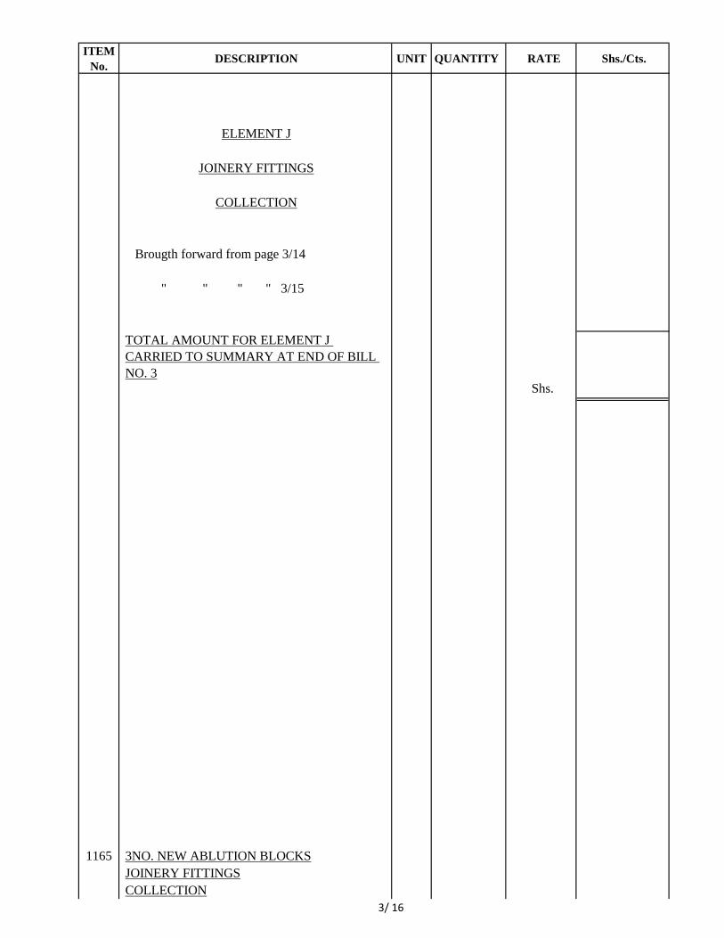
ELEMENT J
JOINERY FITTINGS
COLLECTION
Brougth forward from page 3/14
" " " " 3/15
TOTAL AMOUNT FOR ELEMENT J
CARRIED TO SUMMARY AT END OF BILL
NO. 3
Shs.
1165 3NO. NEW ABLUTION BLOCKS
JOINERY FITTINGS
COLLECTION
3/ 16
ITEM
No.DESCRIPTION UNIT QUANTITY RATE Shs./Cts.
ELEMENT K
BUILDER'S WORK IN CONNECTION WITH
SPECIALIST SERVICES
Internal plumbing, fire-fighting and drainage
installations.
A. Hole through 150mm reinforced concrete slab for
small pipe and make good. No. 4
B. Do. but large pipe. No. 2
C. Hole through 200mm thick masonry wall for
small pipe and make good. No. 10
D. Cut horizontal or vertical chase in masonry
walling for small pipe and make good. m 15
E. Hole through suspended roof slab for large pipe
including forming colar around pipe. No. 2
Electrical Installation
Cut away for and make good after electrician
installing concealed conduit system to the
following points including cutting or leaving
holes, notches, mortices, sinking in both the
structure and its coverings and make good to
them.
F. Lighting points No. 16
G. Lighting switch points. No. 16
TOTAL AMOUNT FOR ELEMENT K
CARRIED TO SUMMARY AT THE END OF
BILL NO.3 Shs.
1165 3NO. NEW ABLUTION BLOCKS
B.W.I.C.
COLLECTION
3/ 17
ITEM
No.DESCRIPTION UNIT QUANTITY RATE Shs./Cts.
ELEMENT L
EXTERNAL WORKS
PAVED AREAS
A. Excavate oversite to reduce levels commencing at
existing ground level and not exceeding 1.50m
deep.m3 14
B. Extra over excavation for excavating in coral
rock. m3 2
C. Remove surplus excavated material from site. m3 14
D. 300mm Bed of selected hardcore, spread,
levelled, well rammed and consolidated in
150mm layers m2 47
E. Telvar 'W' or other equal and approved weed
killer under paving. m2 47
F. 50mm (Average) sand bed spread and well
compacted to falls and crossfalls and cambers
and finished to receive paving slabs (measured
separately) m2 47
G. 50mm washed aggregate precast concrete (Class
25) paving slabs size 600x600 on 50mm sand
bed(measured separately) bedded jointed and
pointed in cement mortar(1:3) and finished fair
on all exposed surfaces m2 47
TOTAL AMOUNT FOR ELEMENT L
CARRIED TO SUMMARY AT THE END OF
BILL NO. 3 Shs.
1165 3NO. NEW ABLUTION BLOCKS
EXTERNAL WORKS
COLLECTION
3/ 18
ITEM
No.
Amount Shs.
Cts.
Element Page No.
A. 3/3
B. 3/4
C. 3/5
D. 3/7
E. 3/9
F. 3/10
G. 3/11
H. 3/12
I. 3/13
J. 3/16
K
3/17
L 3/18
X 3
SHS.
1165
Builder's Works in Connection with Specialist
Services.
TOTAL AMOUNT OF BILL NO. 3 CARRIED TO FINAL
SUMMARY.
BILL NO. 3
SUMMARY
Internal Wall Finishes.
Floor Finishes.
Ceiling Finishes.
Joinery Fittings
Paved areas
TOTAL FOR 1NO. ABLUTION BLOCK
MULTIPLY BY 3 FOR 3NO. ABLUTION BLOCK
Substructures.
Frame.
External and Internal Walls.
Roof finishes and rainwater disposal
Doors
External Wall Finishes.
Title.
BILL NO.3
3NO. NEW ABLUTION BLOCKS
SUMMARY
(ALL PROVISIONAL)
3/19
ITEM
No.DESCRIPTION UNIT QUANTITY RATE
AMOUNT
Shs./Cts.
BILL NO. 4
ENABLING WORKS FOR KIOSKS
(ALL PROVISIONAL)
SECTION A
6 NO. 40 FEET CONTAINERS
Note: Quantities are measured for one 40ft container
only.
A. Allow for planking and strutting to sides of
excavations. Item
B. Allow for keeping excavations free from all spring and
running water. Item
C. Excavate over site to remove vegetable soil average
150mm deep and cart away. m2 52
D. Excavate foundation trench commencing at reduced
level and not exceeding 1.50m deep. m3 14
E. Extra over excavation for excavating in coral rock. m3 14
F. Return fill and ram selected excavated material around
foundations. m3 7
G. Remove surplus excavated material from site m3 7
Plain Concrete (Class 15)
H. 50mm Blinding under foundations. m2 24
Vibrated reinforced concrete (Class 25)
I. Foundations m3 8
Ribbed bar steel reinforcement as before
J. Assorted bar reinforcement bars in foundations. Kg. 400
K. Steel wire fabric mesh reinforcement to B.S. 4483 Ref:
A 193 and K.S. 02 - 18: 1976 in concrete bed
(measeured net, no allowance made for minimum
225mm laps) including tying and supporting as
required. m2 12
Sawn formwork
L. Sides of foundations. m2 26
Shs.
1165 ENABLING WORKS FOR KIOSKS
COLLECTION
4/ 1
ITEM
No.DESCRIPTION UNIT QUANTITY RATE
AMOUNT
Shs./Cts.
SECTION A
6 NO. 40 FEET CONTAINERS
COLLECTION
Brought forward from Page No. 4/1
TOTAL FOR 1NO. 40 FEET CONTAINER Shs.
MULTIPLY BY 6 FOR 6NO. 40 FEET
CONTAINERS Shs. X 6
TOTAL AMOUNT FOR SECTION A CARRIED TO
SUMMARY AT THE END OF BILL NO. 4
Shs.
1165 ENABLING WORKS FOR KIOSKS
SECTION A
COLLECTION
4/ 2
ITEM
No.DESCRIPTION UNIT QUANTITY RATE
AMOUNT
Shs./Cts.
SECTION B
13No. 20 FEET CONTAINERS
Note: Quantities are measured for one 20 feet container
only.
A. Allow for planking and strutting to sides of
excavations. Item
B. Allow for keeping excavations free from all spring and
running water. Item
C. Excavate over site to remove vegetable soil average
150mm deep and cart away. m2 20
D. Excavate foundation trench commencing at reduced
level and not exceeding 1.50m deep. m3 3
E. Extra over excavation for excavating in coral rock. m3 3
F. Return fill and ram selected excavated material around
foundations. m3 1
G. Remove surplus excavated material from site m3 2
Plain Concrete (Class 15)
H. 50mm Blinding under foundations. m2 11
Vibrated reinforced concrete (Class 25)
I. Foundations m3 4
Ribbed bar steel reinforcement as before
J. Assorted bar reinforcement bars in foundations. Kg. 200
Sawn formwork
K. Sides of foundations. m2 13
Shs.
1165 ENABLING WORKS FOR KIOSKS
SECTION B
COLLECTION
4/ 3
ITEM
No.DESCRIPTION UNIT QUANTITY RATE
AMOUNT
Shs./Cts.
SECTION B
13No. 20 FEET CONTAINERS
COLLECTION
Brought forward from Page No. 4/3
TOTAL FOR 1NO. 20 FEET CONTAINER Shs.
MULTIPLY BY 13 FOR 13 NO. 20 FEET
CONTAINERS Shs. X 13
TOTAL AMOUNT FOR SECTION B CARRIED TO
SUMMARY AT THE END OF BILL NO. 4
Shs.
1165 ENABLING WORKS FOR KIOSKS
SECTION B
COLLECTION
4/ 4
ITEM
No.DESCRIPTION UNIT QUANTITY RATE
AMOUNT
Shs./Cts.
SECTION C
6NO. SERVICE AREAS
Note: Quantities are measured for one service area
only.
A. Allow for planking and strutting to sides of
excavations. Item
B. Allow for keeping excavations free from all spring and
running water. Item
C. Excavate over site to remove vegetable soil average
150mm deep and cart away. m2 10
D. Excavate foundation trench commencing at reduced
level and not exceeding 1.50m deep. m3 3
E. Extra over excavation for excavating in coral rock. m3 3
F. Return fill and ram selected excavated material around
foundations. m3 1
G. Remove surplus excavated material from site m3 2
Plain Concrete (Class 15)
H. 50mm Blinding under foundations. m2 3
Vibrated reinforced concrete (Class 25)
I. Foundations m3 1
Ribbed bar steel reinforcement as before
J. Assorted bar reinforcement bars in foundations. Kg. 50
Sawn formwork
K. Sides of foundations. m2 3
L. 150mm Approved load bearing (7N/mm2) coral block
walling in cement mortar (1:3). m2 12
Shs.
1165 ENABLING WORKS FOR KIOSKS
SECTION C
4/ 5
ITEM
No.DESCRIPTION UNIT QUANTITY RATE
AMOUNT
Shs./Cts.
A. 15mm Cement and sand (1:4) external rendering to
plinth finished smooth with a wood float. m2 3
B. Prepare and apply one undercoat and two finishing
coats of bituminous paint or other equal an approved
water resistant paint on rendered plinth. m2 3
Precast concrete (class 25) bedded, jointed and pointed
in gauged mortar.
C. 350 x 70mm Coping twice throated and once weathered
and reinforced as necessary for handling and finished
fair on all exposed surfaces. m 8
D. Approved Swahili patterned concrete breeze blocks to
approval. m 4
Pluvex No. 1 or other equal and approved horizontal
bitumen damp proof course to B.S. 743 (measured net -
no allowance made for laps)
E. 150mm Wide under coping. m 5
Wall Finishes
F. 100mm Thick smooth dressed zero jointed cut-coral
cladding on rendered wall bedded and jointed on and
including 15mm cement and sand (1:3) backing
including all necessary ties and finished with brush
applied protective silicone sealant. m2 9
G. 12mm Two coat internal lime plaster (cement, lime
and riversand 1:2:9) on walls finished smooth with a
steel trowel. m2 9
The whole of the following work is to be executed by
an approved Sub-Contractor.
H. Prepare and apply one undercoat and two finishing
coats of 'Jotun Paints' or other equal and approved
Marine quality paint on plastered walls internally.m2 9
Shs.
1165 ENABLING WORKS FOR KIOSKS
SECTION C
4/ 6
ITEM
No.DESCRIPTION UNIT QUANTITY RATE
AMOUNT
Shs./Cts.
Paved Areas
A. Excavate oversite to reduce levels commencing at
existing ground level and not exceeding 1.50m deep. m3 4
B. Extra over excavation for excavating in coral rock. m3 1
C. Remove surplus excavated material from site. m3 4
D. 150mm Bed of selected hardcore, spread, levelled, well
rammed and consolidated in 150mm layers m2 12
E. Telvar 'W' or other equal and approved weed killer
under paving. m2 12
F. 50mm (Average) sand bed spread and well compacted
to falls and crossfalls and cambers and finished to
receive paving slabs (measured separately)
m2 12
G. 50mm washed aggregate precast concrete (Class 25)
paving slabs size 600x600 on 50mm sand
bed(measured separately) bedded jointed and pointed
in cement mortar(1:3) and finished fair on all exposed
surfaces m2 12
Joinery Fittings
The following in 2 No.Concrete Troughs
Vibrated reinforced concrete (Class 25)
H. 75mm suspended slab. m2 2
I. 75 x 50mm upstand m 4
J. Steel wire fabric mesh reinforcement Ref:A 142 in
suspended concrete trough otherwise as before. m2 2
Sawn formwork
K. Soffit of suspended concrete slab. m2 2
Shs.
1165 ENABLING WORKS FOR KIOSKS
SECTION C
4/ 7
ITEM
No.DESCRIPTION UNIT QUANTITY RATE
AMOUNT
Shs./Cts.
A. Edge of suspended concrete slab not exceeding 75mm
high m 5
B. Do. Edges of upstand. m 1
C. 75mm Chase in stone wall for building in end of 75mm
concrete slab. m 6
Polished Terrazzo
D. 20mm paving on concrete worktop m2 2
E. 75mm high finish to edges of worktop m 5
Builder's Work in connection with specialist services
Internal plumbing, fire-fighting and drainage
installations.
F. Hole through 200mm thick masonry wall for small pipe
and make good. No. 10
G. Cut horizontal or vertical chase in masonry walling for
small pipe and make good. m 2
Electrical Installation
Cut away for and make good after electrician installing
concealed conduit system to the following points
including cutting or leaving holes, notches, mortices,
sinking in both the structure and its coverlug and make
good to them.
H. Lighting points No. 10
I. Lighting switch points. No. 10
J. Consumer unit point. No. 1
Shs.
1165 ENABLING WORKS FOR KIOSKS
SECTION C
4/ 8
ITEM
No.DESCRIPTION UNIT QUANTITY RATE
AMOUNT
Shs./Cts.
SECTION C
6NO. SERVICE AREAS
COLLECTION
Brought forward from Page No. 4/5
" " " " " " 4/6
" " " " " " 4/7
" " " " " " 4/8
TOTAL FOR 1NO. SERVICE AREA Shs.
MULTIPLY BY 6 FOR 6 NO. SERVICE AREAS Shs. X 6
TOTAL AMOUNT FOR SECTION C CARRIED TO
SUMMARY AT THE END OF BILL NO. 4
Shs.
1165 ENABLING WORKS FOR KIOSKS
SECTION C
COLLECTION
4/ 9
ITEM
No.
AMOUNT
Shs. Cts.
Section Page No.
A. 4/2
B. 4/4
C. 4/9
SHS.
1165
Title.
BILL NO.4
ENABLING WORKS FOR KIOSKS
SUMMARY
(ALL PROVISIONAL)
TOTAL AMOUNT OF BILL NO. 4 CARRIED TO FINAL
SUMMARY.
BILL NO. 4
SUMMARY
6No. 40 Feet Containers
13No. 20 Feet Containers
6No. Service Areas
4/10
ITEM
No.DESCRIPTION UNIT QUANTITY RATE
AMOUNT
Shs./Cts.
BILL NO. 5
REFUSE COLLECTION AREA
(ALL PROVISIONAL)
Substructures
A. Allow for planking and strutting to sides of
excavations. Item
B. Allow for keeping excavations free from all spring
and running water. Item
C. Excavate over site to remove vegetable soil
average 150mm deep and cart away. m2 25
D. Excavate foundation trench commencing at
reduced level and not exceeding 1.50m deep. m3 30
E. Extra over excavation for excavating in coral rock.
m3 30
F. Return fill and ram selected excavated material
around foundations. m3 10
G. Remove surplus excavated material from site m3 20
Selected Hardcore
H. Filling in making up levels under floor, spread,
levelled, well rammed and consolidated in 150mm
layers. m3 13
I. 300mm Bed of selected sub-grade material
compacted in layers not exceeding 150mm thick. m2 21
J. Approved insecticide treatment. m2 21
K. 1000 Gauge 'Diothene' or other equal and
approved polythene sheeting as damp proof
membrane laid on blinded hardcore (measured
separately) with welted laps (measured net-no
allowance made for laps).m2 25
Shs.
1165 REFUSE COLLECTION AREA
5/ 1
ITEM
No.DESCRIPTION UNIT QUANTITY RATE
AMOUNT
Shs./Cts.
Plain Concrete (Class 15)
A. 50mm Blinding under foundations. m2 12
Vibrated reinforced concrete (Class 25)
B. Foundations m3 3
C. 200mm Bed laid on damp proof membrane
(measured separately) in bays not exceeding 50
square metre including formwork to edge of bays.m2 25
Ribbed bar steel reinforcement as before
D. Assorted bar reinforcement bars in foundations. Kg. 150
E. Steel wire fabric mesh reinforcement to B.S. 4483
Ref: A 193 and K.S. 02 - 18: 1976 in concrete bed
(measeured net, no allowance made for minimum
225mm laps) including tying and supporting as
required. m2 25
Sawn formwork
F. Sides of foundations. m2 10
G. Edge of bed 75- 150mm high. m2 20
H. 200mm Approved load bearing (7N/mm2) coral
block walling in cement mortar (1:3). m2 25
I. 15mm Cement and sand (1:4) external rendering to
plinth finished smooth with a wood float. m2 8
J. Prepare and apply one undercoat and two finishing
coats of bituminous paint or other equal an
approved water resistant paint on rendered plinth.
m2 8
Shs.
1165 REFUSE COLLECTION AREA
5/ 2
ITEM
No.DESCRIPTION UNIT QUANTITY RATE
AMOUNT
Shs./Cts.
External Walls
Precast concrete (class 25) bedded, jointed and
pointed in gauged mortar.
A. 350 x 70mm Coping twice throated and once
weathered and reinforced as necessary for
handling and finished fair on all exposed surfaces. m 20
Approved Coral stone walling
B. 200mm Walling with hoop iron reinforcement
where required by the Engineer. m2 42
Pluvex No. 1 or other equal and approved
horizontal bitumen damp proof course to B.S. 743
(measured net - no allowance made for laps)
C. 200mm Wide under coping. m 20
D. 200mm Wide under coping. m 20
Hot-dipped galvanized mild steel gate
E. 3500 x 2100mm Double leaf gate comprising of 25
x 25 x 3mm square hollow section top, bottom and
stiles and hinged on and including 50 x 50 x 4mm
thick angle line frame complete with all necessary
hinges, catches, bolts etc including oiling, easing
and adjusting. No. 1
The whole of the following work is to be executed
by an approved Sub-Contractor.
F. Prepare, touch up primer and paint undercoat and
two finishing coats of 'Crown Paints Solo' or other
equal and approved oil paint on general surfaces or
mild steel doors (both side measured flat overall)
m2 15
Shs.
1165 REFUSE COLLECTION AREA
5/ 3
ITEM
No.DESCRIPTION UNIT QUANTITY RATE
AMOUNT
Shs./Cts.
External Wall Finishes
A. Extra over hand chisel dressed stone walling for
smooth face and pointing with flush neat
horizontal joints formed with a steel rod as the
work proceeds.m2 42
Internal Wall Finishes
B. 12mm Two coat internal lime plaster (cement,
lime and riversand 1:2:9) on walls finished smooth
to receive tiles (mesured separately) m2 29
C. 12mm Approved industrial quality porcelain wall
tiles fixed to plastered walls with and including
approved adhesive and jointed and flush pointed
with grout to match tile. m2 29
Floor Finishes
D. 42mm Cement and Sand (1:3) bed and backing
finished to receive industrial quality tiles
(measured separately). m2 22
E. 200mm Approved non-slip industrial quality
porcelain wall tiles fixed to plastered floor with
and including approved adhesive and jointed and
flush pointed with grout to match tile. m2 22
Paved Areas
F. Excavate oversite to reduce levels commencing at
existing ground level and not exceeding 1.50m
deep. m3 7
G. Extra over excavation for excavating in coral rock.
m3 1
H. Remove surplus excavated material from site. m3 7
Shs.
1165 REFUSE COLLECTION AREA
5/ 4
ITEM
No.DESCRIPTION UNIT QUANTITY RATE
AMOUNT
Shs./Cts.
A. 150mm Bed of selected hardcore, spread, levelled,
well rammed and consolidated in 150mm layers
m2 24
B. Telvar 'W' or other equal and approved weed killer
under paving. m2 24
C. 50mm (Average) sand bed spread and well
compacted to falls and crossfalls and cambers and
finished to receive paving slabs (measured
separately) m2 24
D. 50mm washed aggregate precast concrete (Class
25) paving slabs size 600x600 on 50mm sand
bed(measured separately) bedded jointed and
pointed in cement mortar(1:3) and finished fair on
all exposed surfaces m2 24
Shs.
BILL NO. 5
REFUSE COLLECTION AREA
COLLECTION
Brought forward from Page No. 5/1
" " " " " " 5/2
" " " " " " 5/3
" " " " " " 5/4
" " " " " " 5/5
TOTAL AMOUNT FOR BILL NO. 5 CARRIED
TO FINAL SUMMARY
Shs.
1165 REFUSE COLLECTION AREA
COLLECTION
5/ 5
ITEM
No.DESCRIPTION UNIT QUANTITY RATE Shs./Cts.
BILL NO. 6
(ALL PROVISIONAL)
HARD LANDSCAPE AREAS
SECTION A
MATATU INTERCHANGE PARKING AND
DRIVEWAY
A. Excavate oversite to reduce level commencing at
existing ground level not exceeding 1.50m deep. m3 2,100
B. Extra over excavation for excavating in Coral
rockm3 240
C. Remove surplus excavated material from site. m3 2,100
D. Approved murram in making up levels, spread,
levelled, watered and well rammed and
consolidated in 150mm layers. m3 1,200
E. Grade bottoms of excavations or surfaces of
filling to falls and crossfalls including rolling and
compacting to 95% MDD compaction. m2 6,000
F. Tevlar 'W' or other equal and approved weed
killer under driveways and parking. m2 6,000
G. 300mm Bed of selected sub-grade material
compacted in layers not exceeding 150mm thick
to 95% MDD. m2 6,000
H. 200mm Bed of approved gravel sub-base
(minimum 30% CBR) or graded crushed stones. m2 6,000
I. 50mm Bed of approved sand/stone dust blinding
finished to receive paving (measured separately). m2 6,000
J. 60mm Thick medium duty 'Bamburi Blox' or
other equal and approved precast concrete paving
in approved pattern laid on sand bed (measured
separately) to falls, crossfalls, and cambers
including necessary compaction. m2 3,200
K. Take delivery from store cabro and fix only
including necessary compaction. m2 2,800
Shs.
1165 MATATU INTERCHANGE PARKING AND
DRIVEWAY
6/ 1
ITEM
No.DESCRIPTION UNIT QUANTITY RATE Shs./Cts.
A. 125 x 250mm Precast concrete (Class 20) kerb
with one chamfered edge finished fair on all
exposed surfaces bedded, jointed and pointed in
cement mortar (1:3) on and including 325 x
100mm plain concrete (1:3:6) foundation
haunched up on one side including all necessary
excavation, formwork and soil disposal. m 800
B. 125 x 100mm Precast concrete (class 20) channel
finished fair on all exposed surfaces bedded,
jointed and pointed in cement mortar (1:3) laid on
and including 375 x 100mm Plain concrete (1:3:6)
foundation haunched up on both sides including
all necessary excavation, formwork and soil
disposal. m 800
C. Prepare and apply three coats of 'Crown Paints
Solo' or other equal and approved yellow road
marking enamel paint 100mm wide on surfaces of
parking to be executed by an approved Sub-
Contractor. m 400
Shs.
SECTION A
MATATU INTERCHANGE PARKING AND
DRIVEWAY
COLLECTION
Brought forward from Page No. 6/1
" " " " " 6/2
TOTAL AMOUNT OF SECTION A CARRIED
TO SUMMARY OF BILL NO. 6 Shs.
1165 MATATU INTERCHANGE PARKING AND
DRIVEWAY
COLLECTION
6/ 2
ITEM
No.DESCRIPTION UNIT QUANTITY RATE Shs./Cts.
SECTION B
PROMENADE
A. Excavate oversite to reduce level commencing at
existing ground level not exceeding 1.50m deep. m3 1,080
B. Extra over excavation for excavating in coral rockm3 108
C. Remove surplus excavated material from site. m3 1,080
D. Grade bottoms of excavations or surfaces of
filling to falls and crossfalls including rolling and
compacting to 95% MDD compaction. m2 1,800
E. Tevlar 'W' or other equal and approved weed
killer under driveways and parking. m2 1,800
F. Approved murram in making up levels, spread,
levelled, watered and well rammed and
consolidated in 150mm layers. m3 540
G. 200mm Bed of selected sub-grade material
compacted in layers not exceeding 150mm thick
to 95% MDD. m2 1,800
H. 50mm Bed of approved sand/stone dust blinding
finished to receive paving (measured separately). m2 1,800
J. 60mm Thick medium duty normal grey 'Bamburi
Blox' or other equal and approved precast
concrete quad paving in approved pattern laid on
sand bed (measured separately) to falls,
crossfalls, and cambers including necessary
compaction. m2 1,260
K. Do. but with approved colour topping. m2 540
J. 125 x 100mm Precast concrete (class 20) channel
finished fair on all exposed surfaces bedded,
jointed and pointed in cement mortar (1:3) laid on
and including 375 x 100mm Plain concrete (1:3:6)
foundation haunched up on both sides including
all necessary excavation, formwork and soil
disposal. m 720
TOTAL AMOUNT OF PROMENADE
CARRIED TO BILL NO. 6 SUMMARY Shs.
1165 PROMINADE
COLLECTION
6/ 3
ITEM
No.DESCRIPTION UNIT QUANTITY RATE Shs./Cts.
SECTION C
BEACH FRONT SQUARE
(ALL PROVISIONAL)
A. Excavate oversite to reduce level commencing at
existing ground level not exceeding 1.50m deep. m3 600
B. Extra over excavation for excavating in coral
rock m3 60
C. Remove surplus excavated material from site. m3 600
D. Approved murram in making up levels, spread,
levelled, watered and well rammed and
consolidated in 150mm layers. m3 180
E. Grade bottoms of excavations or surfaces of
filling to falls and crossfalls including rolling and
compacting to 95% MDD compaction. m2 2,000
F. Tevlar 'W' or other equal and approved weed
killer under driveways and parking. m2 2,000
G. 300mm Bed of selected sub-grade material
compacted in layers not exceeding 150mm thick
to 95% MDD. m2 2,000
H. 150mm Bed of approved gravel sub-base
(minimum 30% CBR) or graded crushed stones. m2 2,000
I. 50mm Bed of approved sand/stone dust blinding
finished to receive paving (measured separately). m2 2,000
J. 60mm Thick medium duty 'Bamburi Blox' or
other equal and approved natural grey quad paver
blocks in appoved pattern laid on sand bed
(measured separately) to falls, crossfalls, and
cambers including necessary compaction.m2 1,400
K. Do. but in approved red colour topping m2 600
L. 125 x 250mm Precast concrete (Class 20) kerb
with one chamfered edge finished fair on all
exposed surfaces bedded, jointed and pointed in
cement mortar (1:3) on and including 325 x
100mm plain concrete (1:3:6) foundation
haunched up on one side including all necessary
excavation, formwork and soil disposal. m 300
Shs.
1165 BEACHFRONT SQUARE
COLLECTION
6/ 4
ITEM
No.DESCRIPTION UNIT QUANTITY RATE Shs./Cts.
A. 125 x 100mm Precast concrete (class 20) channel
finished fair on all exposed surfaces bedded,
jointed and pointed in cement mortar (1:3) laid on
and including 375 x 100mm Plain concrete (1:3:6)
foundation haunched up on both sides including
all necessary excavation, formwork and soil
disposal. m 300
SECTION C
BEACHFRONT SQUARE
COLLECTION
Brought forward from Page No. 6/4
" " " " " 6/5
TOTAL AMOUNT OF SECTION C CARRIED
TO SUMMARY OF BILL NO. 6 Shs.
1165 BEACHFRONT SQUARE
COLLECTION
6/ 5
ITEM
No.DESCRIPTION UNIT QUANTITY RATE Shs./Cts.
SECTION D
NEW ACCESS ROAD
(ALL PROVISIONAL)
A. Excavate oversite to reduce levels commencing at
existing ground level not exceeding 1.50m deep. m3 540
B. Extra over excavation for excavating in coral
rock.
m3 54
C. Remove surplus excavated material from site. m3 540
D. Grade bottoms of excavations or surfaces of
filling to falls and crossfalls including rolling and
compacting to 95% MDD compaction. m2 1,800
E. Tevlar 'W' or other equal and approved weed
killer under driveways and parking. m2 1,800
F. 150mm Bed of selected sub-grade material
compacted in layers not exceeding 150mm thick
to 95% MDD. m2 1,800
G. 125mm Bed of gravel finish compacted to
standard specifications for roads and to approval
of the Civil Engineer (First layer). m2 1,800
H. Do. (Second layer) m2 1,800
TOTAL AMOUNT OF SECTION D CARRIED
TO SUMMARY OF BILL NO. 6 Shs.
1165 NEW ACCESS ROAD
COLLECTION
6/ 6
ITEM
No. Shs. Cts.
Section Page No.
A. 6/2
B 6/3
C 6/5
D 6/6
SHS.
1165
BILL NO. 6
HARD LANDSCAPE AREAS
SUMMARY
Title.
SUMMARY
(ALL PROVISIONAL)
TOTAL AMOUNT OF BILL NO. 6 CARRIED TO FINAL
SUMMARY.
BILL NO. 6
Matatu Interchange Parking and Driveway
Prominade
Beachfront Square
New Access Road
6/8
ITEM
No. DESCRIPTION UNIT QUANTITY RATE Shs./Cts.
BILL NO. 7
STORMWATER DRAINAGE
(ALL PROVISIONAL)
A. Excavate trench in fill for 450mm diameter
pipe not exceeding 1.50m deep and average
750mm deep, part return fill in and ram and
remainder remove from site. m 90
B. Excavate trench in fill for 300mm diameter
pipe not exceeding 1.50m deep and average
500mm deep, part return fill in and ram and
remainder remove from site. m 89
C. Excavate trench in fill for 200mm diameter
upvc pipe not exceeding 1.50m deep and
average 500mm deep, part return fill in and ram
and remainder remove from site. m 201
D. Excavate for 'V' section open invert block drain
not exceeding 1.50m deep, average 800mm
deep and 1100mm wide and cart away and trim
sides to slope. m 200
E. 450mm Diameter precast concrete ogee jointed
drain pipe to B.S. 556 laid and jointed in trench
and bedded on and including 750mm wide x
200mm thick plain concrete (1:3:6) bed and
surround all round with 150mm thick plain
concrete (1:3:6) including all necessary
formwork (culvert) m 60
F. Do. but laid on with and including approved
granular fill soround. m 30
Shs.
1165 STORMWATER DRAINAGE
7/1
ITEM
No. DESCRIPTION UNIT QUANTITY RATE Shs./Cts.
A. 300mm Diameter precast concrete ogee jointed
drain pipe to B.S. 556 laid and jointed in trench
and bedded on and including 600mm wide x
200mm thick plain concrete (1:3:6) bed and
surround all round with 150mm thick plain
concrete (1:3:6) including all necessary
formwork (culvert) m 29
B. Do. but laid on and with and including
approved granular fill soround. m 60
C. Precast concrete (class 25) rainwater channel
comprising 600mm long rectangular invert
blocks each 600 x 300mm high with two top
edges each twice splayed and 400mm wide x
200mm deep sinking on top, finished fair and
reinforced as necessary for handling, bedded,
jointed and pointed on and including 50mm bed
of plain concrete (1:4:8) and with 100mm thick
murram backfilling to bottom and both sides.
m 200
D. 75mm Precast concrete (class 25) side slabs
size 600 x 225mm finished fair, bedded on and
including 75mm murram well compacted to
sides and slopes of rainwater channel and
pointed in cement mortar (1:3). m2 270
E. 200mm Diameter Upvc drain pipe laid and
jointed in trench. m 201
F. 150mm Plain concrete (1:3:6) bed 300mm wide
under 200mm pipe and soround pipe with
simillar concrete 150mm thick including all
necessary formwork. m 50
Shs.
1165 STORMWATER DRAINAGE
7/2
ITEM
No. DESCRIPTION UNIT QUANTITY RATE Shs./Cts.
A. Inspection chamber size 900 x 900 x 1000mm
deep internally with 150mm thick natural stone
walls, 150mm reinforced concrete (class 20)
base and cover slab complete with and
including 600 x 600mm medium duty cast iron
manhole cover and frame, plain concrete
(1:3:6) benching and channels, 15mm
waterproof cement and sand (1:5) rendering to
walls and base including all necessary
reinforcement, formwork, cutting existing slab,
excavation, backfill and soil disposal. No. 6
B. Road gully size 450 x 450 x 600mm deep
internally 50mm plain concrete (1:3:6) blinding
with 150mm thick masonry walls, 150mm
reinforced concrete (class 20) base and toping
complete with and including 40 x 3mm flat
galvanized mild steel grating cover at 40mm
centres welded to 50 x 50 x 3mm mild steel
angle frame, 15mm waterproof cement and
sand (1:5) rendering to walls and base
including all necessary reinforcement,
formwork, excavation, backfill and soil
disposal. No. 32
The following in 6No. Headwalls
C. Excavate in fill for headwall not exceeding
1.50m deep. m3 105
D. Return fill in and ram selected excavated
material around headwall. m3 42
E. Remove surplus excavated material from site. m3 63
Vibrated reinforced concrete (class 25)
F. 150mm Base slab. m2 47
G. 150mm Head wall. m2 40
Shs.
1165 STORMWATER DRAINAGE
7/3
ITEM
No. DESCRIPTION UNIT QUANTITY RATE Shs./Cts.
A. Steel wire fabric mesh reinforcement to B.S.
4483 Ref. A193 otherwise as before in base
slab and headwall. m2 87
Sawn formwork
B. Edge of base 75 - 150mm high. m2 70
C. Sides of headwall. m2 80
D. Upper surfaces of wall sloping more than 15
degrees from the horizontal. m2 5
E. Hole through 150mm reinforced concrete wall
for 450mm diameter pipe and make good. No. 6
French Drains
F. Excavate trench French drains commencing at
existing ground level not exceeding 1.50m
deep. m3 184
G. Extra over for excavation in coral rock. m3 20
H. Remove surplus excavated materials from site m2 184
Selected fill material
I. 150mm Bed of top vegetation soil to approval. m2 260
J. 20-60 Crushed agregates laid to approval. m3 115
K. 500 Guage approved polythene sheeting laid on
coral base as a damp proof membrane
(measured net-no allowance) m2 320
Shs.
1165 STORMWATER DRAINAGE
7/4
ITEM
No. DESCRIPTION UNIT QUANTITY RATE Shs./Cts.
Pipe and geotextile membrane
A. 150mm Diameter perforated Upvc pipe, laid at
a minimum slope of 1:200 and 3/4 perforated
using, 16mm diameter hole staggered about
with and including approved geotextile
membrane surround all to the entire satisfaction
of the Civil Engineer. m 440
B. Allow for testing the whole of the stormwater
drainage during the progress of the works and
again on completion and leave in perfect
working order to the satisfaction of the
Architect. Item 1
Shs.
BILL NO 7
STORMWATER DRAINAGE
COLLECTION
Brought forward from Page No. 7/1
" " " " " 7/2
" " " " " 7/3
" " " " " 7/4
" " " " " 7/5
TOTAL AMOUNT OF BILL NO. 7 CARRIED
TO FINAL SUMMARY Shs.
1165 STORMWATER DRAINAGE
COLLECTION
7/5
ITEM
No. DESCRIPTION UNIT QUANTITY RATE Shs./Cts.
BILL NO. 8
FOUL DRAINAGE
(ALL PROVISIONAL)
A. Excavate trench for drain pipe exceeding
150mm diameter not exceeding 1.50m deep and
average 600mm deep part return fill in and ram
and remainder remove from site. m 150
B. Do. but average 1000mm deep. m 150
C. Do. but average 1500mm deep. m 100
D. Do. but average 2000mm deep. m 100
E. 160mm Diameter UPVC golden brown class 41
drain pipe laid and jointed in trench. m 350
F. 200mm Do. m 150
G. 150mm Plain concrete (1:3:6) bed 600mm wide
under 160mm diameter pipe and surround pipe
with simillar concrete 150mm thick including
all necessary formwork. m 150
H. Do. but 700mm wide under 200mm diameter
pipe. m 75
I. Oil interceptor overall size 5600 x 1600 x
2050mm deep in three interconnected
compartments constructed of 200mm thick
reinforced concrete (class 25) base and cover
slab, 150mm reinforced concrete walls, 3No.
openings for and including 600 x 450mm heavy
duty covers and frames to BS 497, 100mm
diameter PVC interconnecting Pipes grouted in
concrete, 50mm diameter PVC vent pipe with
anti-bat gauze discharging approximately 10m
away as directed, 500 x 300 x 400mm
galvanized perforated bucket with handle on
and including an approved sand bed complete
with and including all necessary excavations,
cart away, backfill, formwork, reinforcement,
waterproofing and finishes to the architect's
approval. No. 2
Shs.
1165 FOUL DRAINAGE
8/1
ITEM
No. DESCRIPTION UNIT QUANTITY RATE Shs./Cts.
A. Soak pit overall size 1600mm diameter x
3500mm deep internally approved and selected
hardcore filling with 150mm thick natural stone
walls on 150mm reinforced concrete (class 20)
cover slab and base blinded with 50mm plain
concrete (1:3:6), 1No oppening for and
including 600 x 450mm heavy duty covers and
frames to BS 497, 15mm waterproof cement
and sand (1:5) rendering to walls including all
necessary reinforcement, formwork,
excavation, backfill and soil disposal. No. 4
B. Allow for testing the whole of the foul drainage
during the progress of the works and again on
completion and leave in perfect working order
to the satisfaction of the Architect. Item 1
Shs.
BILL NO. 8
FOUL DRAINAGE
COLLECTION
Brought forward from Page No. 8/1
" " " " " 8/2
TOTAL AMOUNT OF BILL NO. 8 CARRIED
TO FINAL SUMMARY Shs.
1165 FOUL DRAINAGE
COLLECTION
8/2
ITEM DESCRIPTION UNIT QTY RATE KSHS AMOUNT KSHS
E1 ABLUTION BLOCK INSTALLATIONS
E1.1 LIGHTING SYSTEM
E1.1.01 Supply, install, Test and Commission 3No. X 1.5Sq. mm colour-coded Single Core Copper Cables to lighting points drawn in 20mm Ǿ concealed High Impact Heavy Gauge PVC conduits, complete with draw boxes, switch boxes and all other necessary accessories as detailed in Lighting Layout Contract Drawing.
No. 66
E1.1.02 Supply, install, Test and Commission Lighting Control Switch Plates, complete with all other necessary accessories as detailed in Lighting Layout Contract Drawings for all the Floor Levels.
i One Gang One Way Switch Plates No. 15
ii Motion Sensors No. 3
E1.1.03 Supply, install, Test and Commission the following Lighting Fittings, complete with lamps and all other necessary accessories as detailed in Lighting Layout Contract Drawings for all the Floor Levels.
i 3.5 Watts LED Ceiling Recessed Light Fitting No. 15
ii Lighting Point Type LP No. 51
E1.1TOTAL FOR E3.1 - LIGHTING INSTALLATIONS CARRIED FORWARD TO COLLECTION PAGE 9/4
E1.2 SMALL POWER POINTS
E1.2.01 Supply, install, Test and Commission 3No. X 2.5Sq. mm colour-coded Single Core Copper Cables Radial Circuits drawn in 20mmǾ concealed High Impact Heavy Gauge PVC conduits, complete with switch boxes and all other necessary accessories - but excluding the power point face plates as detailed in Small Power Layout Contract Drawing. No. 6
E1.2.02 Supply, install, Test and Commission the following Power Point Accessories as detailed in Small Power Layout Contract Drawings for all Floor Levels.
i 20 Amps Double Pole Switch with neon indicator. No. 6
E1.2TOTAL FOR E3.2 - SMALL POWER INSTALLATIONS CARRIED FORWARD TO COLLECTION PAGE 9/4
ELECTRICAL INSTALLATION WORKS (ALL PROVISIONAL)
BILL NO. 9
9/1
ITEM DESCRIPTION UNIT QTY RATE KSHS AMOUNT KSHS
ELECTRICAL INSTALLATION WORKS (ALL PROVISIONAL)
BILL NO. 9
E1 ABLUTION BLOCK INSTALLATIONS - Continued
E1.3 CABLE WAYS & ELECTRICAL CONNECTION TO MECHANICAL EQUIPMENT
Please Refer To Lighting and Small Power Drawings -
E1.3.01 Supply, install, Test and Commission 3Core X 2.5Sq. mm PVC SWA PVC Copper Cable drawn in Ducts, complete with switch boxes and all other necessary accessories and 20 Amps Double Pole Switch face plates, for Drainage Pump as detailed in Small Power Layout Contract Drawing. LM 0
E1.3.02 Supply, install, Test and Commission 3Core X 2.5Sq. mm PVC SWA PVC Copper Cable drawn in Ducts, complete with switch boxes and all other necessary accessories and 20 Amps Double Pole Switch face plates, for Circulation Pump as detailed in Small Power Layout Contract Drawing. LM 0
E3.3.03 Supply, install, Test and Commission 3Core X 2.5Sq. mm PVC SWA PVC Copper Cable drawn in Ducts, complete with switch boxes and all other necessary accessories and 20 Amps Double Pole Switch face plates, for Solar Water Heating System as detailed in Small Power Layout Contract Drawing.
LM 0
E1.3.04 Supply, install, Test and Commission 4Core X 2.5Sq. mm PVC SWA PVC Copper Cable drawn in Ducts, complete with switch boxes and all other necessary accessories and 20 Amps Isolator, for Booster Pump as detailed in Small Power Layout Contract Drawing. LM 0
E1.3.05 Supply & Install 20 Amp Isolators for Mechanical Equipment
NOS. 0
E1.3TOTAL FOR E3.3- CABLE WAYS & ELECTRICAL CONNECTION TO MECHANICAL EQUIPMENT CARRIED FORWARD TO COLLECTION PAGE 9/4
9/2
ITEM DESCRIPTION UNIT QTY RATE KSHS AMOUNT KSHS
ELECTRICAL INSTALLATION WORKS (ALL PROVISIONAL)
BILL NO. 9
E1 ABLUTION BLOCK INSTALLATIONS - Continued
E1.4 POWER RETICULATION SYSTEM
METER BOARD
E1.4.01 Supply, install, connect-up complete, Test and Commision Meter Board complete with all accessories to Kenya Power Standards - Enclosure for KP&LC Meter No 3
DISTRIBUTION BOARDS
E1.4.02 Supply, install, connect-up complete, Test and Commision 100 Amp 4 way TP/N MCB Distribution board complete with integral isolator and MCBs. No 3
SUB MAIN CABLE
E1.4.03 Supply, draw in 32mmǾ High Impact Heavy Gauge PVC conduit, complete with all conduit accessories, connect-up complete, Test and Commision, 4Core X 25Sq. mm PVC SWA PVC Copper Cable from Authority Power Supply to the Main Distribution Board. LM 30
EARTHING SYSTEM
E1.4.04 Supply, install, connect-up complete, Test and Commision, Distribution Boards Earthing Systems for the installations, to Kenya Power Standards. No. 3
E1.4.05 Supply, draw in 20mmǾ High Impact Heavy Gauge PVC conduit, complete with all conduit accessories, connect-up complete, Test and Commision, 1No. X 16Sq. mm copper earth cable from Earthing Points to respective connections. LM 30
E1.4TOTAL FOR E3.4 - POWER RETICULATION SYSTEM CARRIED FORWARD TO COLLECTION PAGE 9/4
9/3
ITEM DESCRIPTION UNIT QTY RATE KSHS AMOUNT KSHS
ELECTRICAL INSTALLATION WORKS (ALL PROVISIONAL)
BILL NO. 9
E1 ABLUTION BLOCK INSTALLATIONS - Continued B/F
PAGE NO.
COLLECTION PAGE KSHS.
E1.1 TOTAL FOR E3.1 - LIGHTING INSTALLATIONS 9/1
E1.2 TOTAL FOR E3.2 - SMALL POWER INSTALLATIONS 9/1
E1.3 TOTAL FOR E3.3- CABLE WAYS & ELECTRICAL CONNECTION TO
MECHANICAL EQUIPMENT 9/2
E1.4 TOTAL FOR E3.4 - POWER RETICULATION SYSTEM 9/3
E1 TOTAL E3 ABLUTION BLOCK INSTALLATIONS CARRIED TO SUMMARY (PAGE 9/11)
9/4
ITEM DESCRIPTION UNIT QTY RATE KSHS AMOUNT KSHS
ELECTRICAL INSTALLATION WORKS (ALL PROVISIONAL)
BILL NO. 9
E12 GATEWAYS (1 No.) INSTALLATIONS
E2.1 LIGHTING SYSTEM
E2.1.01 Supply, install, Test and Commission 3No. X 1.5Sq. mm colour-coded Single Core Copper Cables to lighting points drawn in 20mm Ǿ concealed High Impact Heavy Gauge PVC conduits, complete with draw boxes, switch boxes and all other necessary accessories as detailed in Lighting Layout Contract Drawing.
No. 9
E2.1.02 Supply, install, Test and Commission Lighting Control Switch Plates, complete with all other necessary accessories as detailed in Lighting Layout Contract Drawings for all the Floor Levels.
i One Gang One Way Switch Plates No. 3
ii Motion Sensors No. 2
E2.1.03 Supply, install, Test and Commission the following Lighting Fittings, complete with lamps and all other necessary accessories as detailed in Lighting Layout Contract Drawings for all the Floor Levels.
i Lighting Point Type LP No. 18
E2.1TOTAL FOR E4.1 - LIGHTING INSTALLATIONS CARRIED FORWARD TO COLLECTION PAGE 9/7
E2.2 SMALL POWER POINTS
E2.2.01 Supply, install, Test and Commission 3No. X 2.5Sq. mm colour-coded Single Core Copper Cables Radial Circuits drawn in 20mmǾ concealed High Impact Heavy Gauge PVC conduits, complete with switch boxes and all other necessary accessories - but excluding the power point face plates as detailed in Small Power Layout Contract Drawing. No. 3
E2.2.02 Supply, install, Test and Commission the following Power Point Accessories as detailed in Small Power Layout Contract Drawings for all Floor Levels.
i 13 Amps Twin Switched Socket Outlets. No. 3
-
E2.2TOTAL FOR E4.2 - SMALL POWER INSTALLATIONS CARRIED FORWARD TO COLLECTION PAGE 9/7
9/5
ITEM DESCRIPTION UNIT QTY RATE KSHS AMOUNT KSHS
ELECTRICAL INSTALLATION WORKS (ALL PROVISIONAL)
BILL NO. 9
E2 GATEWAYS (1 No.) INSTALLATIONS - Continued
E2.3 POWER RETICULATION SYSTEM
METER BOARD
E2.3.01 Supply, install, connect-up complete, Test and Commision Meter Board complete with all accessories to Kenya Power Standards - Enclosure for KP&LC Meter No 1
DISTRIBUTION BOARDS
E2.3.02 Supply, install, connect-up complete, Test and Commision 100 Amp 4 way TP/N MCB Distribution board complete with integral isolator and MCBs. No 1
SUB MAIN CABLE
E2.3.04 Supply, draw in 32mmǾ High Impact Heavy Gauge PVC conduit, complete with all conduit accessories, connect-up complete, Test and Commision, 4Core X 10Sq. mm PVC SWA PVC Copper Cable from Authority Power Supply to the Main Distribution Board. LM 20
EARTHING SYSTEM
E2.3.05 Supply, install, connect-up complete, Test and Commision, Distribution Boards Earthing Systems for the installations, to Kenya Power Standards. No. 1
E2.3.06 Supply, draw in 20mmǾ High Impact Heavy Gauge PVC conduit, complete with all conduit accessories, connect-up complete, Test and Commision, 1No. X 16Sq. mm copper earth cable from Earthing Points to respective connections. LM 40
E2.4TOTAL FOR E4.4 - POWER RETICULATION SYSTEM CARRIED FORWARD TO COLLECTION PAGE 9/7
9/6
ITEM DESCRIPTION UNIT QTY RATE KSHS AMOUNT KSHS
ELECTRICAL INSTALLATION WORKS (ALL PROVISIONAL)
BILL NO. 9
E2 GATEWAYS (1 No.) INSTALLATIONS - Continued B/F
PAGE NO.
COLLECTION PAGE KSHS.
E2.1 TOTAL FOR E4.1 - LIGHTING INSTALLATIONS 9/5
E2.2 TOTAL FOR E4.2 - SMALL POWER INSTALLATIONS 9/5
E2.3 TOTAL FOR E4.4 - POWER RETICULATION SYSTEM 9/6
E2 TOTAL E4 GATEWAYS (1 No.) CARRIED TO SUMMARY (PAGE 9/11)
E3.1.01 Supply, draw in 32mmǾ High Impact Heavy Gauge PVC conduit, complete with all conduit accessories, connect-up complete, Test and Commision, 4Core X 10Sq. mm PVC SWA PVC Copper Cable from Authority Power Supply complete with Power Tap Off Unit installed within each of the containers.
LM 135
EARTHING SYSTEM
E3.1.02 Supply, install, connect-up complete, Test and Commision, Distribution Boards Earthing Systems for the installations, to Kenya Power Standards. No. 100
E3.1.03 Supply, draw in 20mmǾ High Impact Heavy Gauge PVC conduit, complete with all conduit accessories, connect-up complete, Test and Commision, 1No. X 16Sq. mm copper earth cable from Earthing Points to respective connections. LM 135
E3 TOTAL E3 TYPICAL CONTAINER KIOSKS (100No.) CARRIED TO SUMMARY (PAGE 9/11)
9/8
ITEM DESCRIPTION UNIT QTY RATE KSHS AMOUNT KSHS
ELECTRICAL INSTALLATION WORKS (ALL PROVISIONAL)
BILL NO. 9
E4 STREET LIGHTING INSTALLATIONS
E4.1.01 Supply, draw in ducts (measured separately), Connect-up complete, Test and Commision, 2Core X 2.5Sq. mm PVC SWA PVC Copper Cable from the Control Panels to the Street Lighting Points as detailed in our contruct drawing. LM 1000
E4.1.02 Supply, install with concrete base, connect-up complete, Test and Commision 8 Meter Marine Grade Hot -Dipped Galvanised Street Lighting Poles complete with armstrech bracket to match county government requirements and to approval
No 21
E4.1.03 Supply, install, connect-up complete, Test and Commision 2.5Sq. Mm Twin with Earth Sheathed Copper Cables connecting Lighting fittings with the underground cable via slidlocks within the Poles. LM 60
E4.1.04 Supply, install, connect-up complete, Test and Commision 40W LED Street Light Fittings complete with fixing accessories and to approval No 21
E4.1.05 Supply, install, connect-up complete, Test and Commision, Street Light Earthing Systems for the installations. No. 2
E4.1.06 Supply, install, connect-up complete, Test and Commision, Street Light Control Systems (WEATHERPROOF FEEDER PILLARS) for the installations as detailed in our contract drawing.
No. 5
E4.1.07 Supply, install, connect-up complete, Test and Commision, Feeder Pillars (WEATHERPROOF FEEDER PILLARS) for Power Supply to Container Kiosks the installations as detailed in our contract drawing. No. 5
E4 TOTAL E4 STREET LIGHTING INSTALLATIONS CARRIED TO SUMMARY (PAGE 9/11)
9/9
ITEM DESCRIPTION UNIT QTY RATE KSHS AMOUNT KSHS
ELECTRICAL INSTALLATION WORKS (ALL PROVISIONAL)
BILL NO. 9
E5 SERVICE DUCTS RETICULATION SYSTEM
E5.1.01 Supply, install with concrete surround, 2 X 150mmǾ High Impact Heavy Gauge PVC Duct, for Underground High Voltage Power Distribution System. Existing overhead cables to be redirected into the ducts. LM 1200
E5.1.02 Supply, install with concrete surround, 2 X 100mmǾ High Impact Heavy Gauge PVC Duct, for Underground LOW Voltage Power Distribution System. Existing overhead cables to be redirected into the ducts. LM 1200
E5.1.03 Supply, install with concrete surround, 2 X 100mmǾ High Impact Heavy Gauge PVC Duct, for Underground EXTRA LOW Voltage (FIBRE) Distribution System. LM 1200
E5.1.04 Supply, install 600mm X 600mm Standard Manholes complete with weathertight covers, for HIGH Voltage Distribution System.
No 19
E5.1.05 Supply, install 600mm X 600mm Standard Manholes complete with weathertight covers, for EXTRA LOW and LOW Voltage Distribution System. No 38
E5.1.06 Supply, install with concrete surround, 1 X 50mmǾ High Impact Heavy Gauge PVC Duct, for Underground LOW Voltage Power and Extra Low Voltage Distribution System. Existing overhead cables to be redirected into the ducts. LM 200
E5 TOTAL E5 SERVICE DUCTS RETICULATION SYSTEM CARRIED TO SUMMARY (PAGE 9/11)
Descriptions of materials and workmanship contained in the Bills of Quantities measured items shall take precedence over descriptions contained in Appendices in the event of discrepancies between the two, unless the Architect shall otherwise direct.
DISCREPANCIES IN DRAWINGS
Drawings shall take precedence over the Bills of Quantities, for construction purposes, in the event of discrepancies between the two, and the Architect must be notified immediately any such discrepancy becomes apparent.
TESTS AND SAMPLES
Unless otherwise described in the Bills of Quantities, the Contractor will be responsible for all the costs involved in testing materials as described hereinafter. He will also be responsible for all the costs involved in supplying samples of materials or workmanship as required hereinafter to the satisfaction of the Architect. The cost of replacing materials fixed or placed in position which do not comply with the required test results or approved samples shall be borne solely by the Contractor.
KENYA STANDARDS
All materials and goods supplied for incorporation in the works must comply with any relevant current standards issued by the Kenya Bureau of Standards. Where these are not established or are unclear the latest British Standards and Codes of Practice shall be applied.
EXCAVATION AND EARTHWORKS
SITE CLEARANCE
See Structural Engineers Specification.
GRUBBING
See Structural Engineers Specification.
EXCAVATION
See Structural Engineers Specification
WATER IN EXCAVATIONS
The Contractor shall excavate sumps, cut drains, provide and place all necessary materials and provide and work pumps, plant and apparatus for dealing with any water which may find its way into the excavation from any source whatsoever.
The responsibility for draining away, pumping, or otherwise removing water from the excavations shall rest with the Contractor throughout the duration of the Contract, but methods employed shall be subject to the agreement of the Architect.
F/2
Provision has been made in the Preliminaries and General Conditions of these Bills of Quantities for the Contractor to insert a price against this item.
HARD ROCK
See Structural Engineers Specification
FOUNDATION EXCAVATIONS
See Structural Engineers Specification.
SURPLUS SOIL DISPOSAL
See Structural Engineers Specification.
TOP SOIL FOR SPREADING
See Structural Engineers Specification.
FILLING UNDER SURFACE BED IN BUILDINGS
See Structural Engineers Specification.
FILLING OBTAINED FROM THE EXCAVATIONS
See Structural Engineers Specification.
MATERIALS FOUND IN EXCAVATIONS
See Structural Engineers Specification.
CONCRETE WORK
See Structural Engineers Specification.
WALLING
CEMENT
All cement used for making mortar shall be Portland Cement complying with B.S. 12.
SAND
All sand used for making mortar shall be clean well graded silicone sand of good sharp quality equal to samples which shall be approved by the Architect. It shall be free from lumps of stone, earth, loam, dust, salt, organic matter and any other deleterious substance, sieved through a fine sieve and washed if so directed by the Architect.
LIME
Lime for mortar shall be non-hydraulic or semi-hydraulic quick lime or hydrated lime in accordance with B.S. 890, Class B.
Quick lime shall be run to putty immediately after delivery to site in a pit dug on the site or in approved containers. The water to be first run into the pit or container and
the lime to be added until it is completely submerged and stirred until all lumps are disintegrated and the resulting mild-lime shall then be run through a 3mm square mesh sieve and run into a pit or other container and kept clean and moist for not less than 4 weeks before use.
Hydrated lime shall be added to water in a clean receptacle thoroughly mixed to the consistency of thick cream and allowed to stand and be kept clean and moist for not less than 16 hours before use.
F/3
CEMENT MORTAR
The cement mortar (1:3) shall be composed of 42.5 kgs. of Portland Cement to 0.085 cubic metres of sand. The cement mortar (1:6) shall be composed of 42.5 kgs of Portland Cement to 0.17 cubic metres of sand measured in specially prepared gauge boxes and thoroughly mixed in an approved mechanical mixer or mixed dry on clean and approved mixing platforms with water added afterwards until all parts are completely incorporated and brought to a proper consistency. The use or retempering of wholly or partly set mortar will not be allowed.
Foundation walling up to ground floor slab 1 part cement to 6 parts sand.
GAUGED LIME MORTAR
Gauged lime mortar shall be composed of 2 parts by volume of lime putty to 12 parts by volume of sand measured in specially prepared gauge boxes and mixed dry on clean and approved mixing platforms with water added afterwards until all parts are thoroughly incorporated and brought to a proper consistency.
The mortar shall be mixed 7 to 10 days before it is required for use and shall be stacked in a neat heap well smoothed off, covered with wet sacks and allowed to mature.
Immediately before use 1 part by volume of Portland Cement shall be added to 9 parts by volume of lime mortar, the whole being remixed with the addition of extra water until all parts are completely incorporated and brought to a proper consistency.
The gauged mortar must be used within 45 minutes of being mixed and the use or retempering of wholly or partially set mortar will not be allowed.
Above ground floor slab 1 part cement to 3 parts lime to 15 parts sand.
CONCRETE BLOCKS
Concrete blocks shall be hollow or solid as required and shall be hard, true to size and shape with sharp arrises in accordance with B.S. 2028 type 'A'. They are to be obtained from an approved manufacturer and shall be equal in every respect to a sample to be deposited with and approved by the Architect. Blocks must be cured at least 4 weeks before delivery to site and the Contractor is to order his entire stocks as soon as the Contract is signed. Before bulk delivery commences and thereafter, if the Architect so directs, the Contractor shall dispatch twelve sample blocks to the M.O.W. Materials Testing Laboratory. Should tests indicate that the blocks do not comply with the Specification, the batch from which they were taken shall forthwith be removed and re-executed or otherwise rectified at the Contractor's expense. Blocks shall be generally 390mm long, 190mm high and of the thicknesses required for the walling to be built. Blocks of other sizes will, however, be required to form proper bondings at corners, around openings, etc. and the like positions and the Contractor must make or cut blocks to all the varying sizes required for these purposes.
LOAD BEARING CONCRETE BLOCKS
Blocks described as load bearing shall have the minimum compressive strengths specified for each block, determined and tested in accordance with the appropriate B.S. and to the entire satisfaction of the Architect. Blocks of the various strengths shall be differentiated by means of an approved colour code marking.
COLOURED CONCRETE BLOCKS
Concrete blocks described as coloured shall contain colouring pigment mixed integrally with the materials to produce the required tint or shade. The mix of
F/4
materials contained in the blocks is to be adjusted as and if necessary to maintain the materials to produce the required tint or shade. The mix of materials contained in the blocks is to be adjusted as and necessary to maintain the specifications of strength etc. Unless otherwise described blocks are to be laid jointed and pointed in mortar containing pigment mixed integrally to produce a tint or shade matching that of the blocks. The mix of materials contained in the mortar is to be adjusted as and if necessary to maintain the specifications of strength, etc.
HOLLOW CLAY BLOCKS
Hollow clay blocks are to be hard, well burnt, true to size and shape with sharp arises and keyed faces and joints in accordance with B.S. 1190 Type 'A'. They are to be equal in every respect with a sample to be deposited with and approved by the Architect. The hollow clay blocks are to be bedded and jointed in gauged mortar.
FAIR FACED CONCRETE BLOCKWORK
Fair faced concrete blockwork shall be built in ordinary blocks selected for their uniformity and appearance and shall be free from holes or any other deformities and shall have clean, sharp arises. The blocks shall be built in mortar as described and raked out and pointed with a neat flush joint as the work proceeds, unless otherwise stated. All arises shall be plumb and square, and all joints properly bonded and true to line.
STONE WALLING
The stone for walling shall be sound and hard throughout free from all defects and shall be obtained from a quarry approved by the Architect. Samples shall be submitted for approval and, if approved, shall be regarded as the standard for the work generally. All stone rejected by the Architect shall be removed immediately from the site. Stones shall be laid on their natural beds and properly lapped and bonded and thoroughly wetted before laying and again after laying for at least three days. Stones shall be chisel dressed into true rectangular blocks with each surface even and at right angles to all adjoining surfaces and shall generally be not less than 390mm long, 190mm high and of the thickness required for the walling to be built. Extra over for fair face shall mean 'fine or medium butched chisel dressed' to an even surface, built with a fair face and raked out and pointed with a neat recessed joint as the work proceeds. All arrises shall be plumb and square and all joints properly bonded and true to line. Fine or medium butched chisel dressed walling shall be in regular courses.
If required by the Bills of Quantities, coloured stone walling and fair face dressings shall be as described below:-
1) Fine butched stone shall be either chisel dressed or machine dressed - dress the external face of each stone to the finest face practically obtainable and finish to a fine rubbed plane surface.
2) Medium butched chisel dressed stone - chisel dress the external face of each stone so that chisel marks are approximately the same width, with ridges between adjacent marks approximately in the same plane.
3) Quarry faced stone - do not work the external face of each stone.
4) Random rubble stone facing - stones of random shape, colour and size as facing to backing wall.
5) Random squared medium butched chisel dressed stone - stones of random shape, colour, size and thickness squared and dressed as before described.
F/5
6) Stone walling of approved colour - walling to be built using grey and mixed blue and grey coloured stones.
7) Stone walling of variegated colours - walling to be built using multi colour stone approved by the Architect and mixed in proportions approved by the Architect.
8) Machine dressed stone facing shall be 25mm or 50mm thick as required by the Architect. Machine rotary blade cut stones facing on backing wall.
The finished mortar joint for fine or medium butched chisel dressed stonework is to be 10mm wide and generally 5mm back from the face of the stone. Where directed by the Architect the mortar will be coloured to match the stones.
Stone walling described as load bearing shall have a minimum crushing strength of 10 Newtons per square mm.
On completion all stonework is to be scrubbed down with a wire brush.
BRICK FACINGS
Brick facings shall be of hand scratched bricks size 65mm high x 65mm deep x 230mm long as manufactured by Clayworks Ltd., P.O. Box 48202, Nairobi, with 10mm horizontal joints only raked out 10mm deep as the work proceeds. Wall ties shall be 18 gauge butterfly shaped galvanised mild steel wire staggered at 450mm centres vertically and 900mm centres horizontally. Supports at heads shall be with approved steel angles. Strict supervision of quality will be maintained by the Architect and all work will be in accordance with a sample panel to be approved by the Architect prior to the start of facing works.
WALLING GENERALLY
The Contractor shall provide proper setting out rods and set out all work on same for courses, openings, heights, etc., and shall build the walls, piers, etc., to the widths, depths and heights indicated on the drawings.
Concrete blocks shall be thoroughly wet before being laid and shall be kept wet during that day. Where unfinished work is continued, the completed walling shall be wetted before laying mortar.
All walls throughout the work shall be carried up evenly in 200mm courses, no part being carried up more than 1m higher at one time than any other part, and in such cases the jointing shall be made in long steps so as to prevent cracks arising, and all walls shall be levelled round at each stage. All faces of walls to be plastered are to have all the joints raked out as key for plaster.
Alternate courses of walling at all angles and intersections shall be carried through the full thickness of the adjoining wall. All walling shall be built up entirely solid in blocks, without voids. All perpends, reveals and angles of the walling shall be built strictly true and square and all walling shall be flushed up and grouted solid as the work proceeds.
All putlog holes shall not be less than one course deep and carefully filled with a block cut to fit size of opening with beds and joints filled with mortar well tamped in after scaffolding is removed and if in fair faced wall to match facings.
All walling 150mm thick and under is to be reinforced with one layer of 25mm x 16 B.W.G. hoop iron built into every second course well lapped at joints and intersections and carried at least 115mm into abutting walls at junctions.
Where concrete and stone walling are bonded together at intersections or heading joints the horizontal cement mortar beds shall not exceed 15mm thickness and vertical joints are to be staggered.
F/6
DAMP PROOF COURSES
The damp proof course is to consist of a 25mm screed of cement and sand (1:2) laid over the area of the walls and finished to a level surface and covered with and including an approved fibre based bituminous damp proof course weighing not less than 2.7 kgs. per square metre and lapped 225mm at all joints and intersections. All walls are to be carefully cleaned and wetted before the screed is laid.
OTHER TRADES
Close co-operation with electrical and plumbing Sub-Contractors must be maintained from the beginning of the job to avoid chases being cut in hollow block or 100mm solid block work or across any fair faced work. If necessary, conduits should be run down the jambs of the door openings behind the door frame and taken to the switch position through a horizontal joint in the masonry.
ROOFING
SCREEDS
Roof screeds where specified shall be as described in 'Floor, Wall and Ceiling Finishes'.
GUARANTEE
The Contractor and the Roofing Sub-Contractor are to leave all the roofs complete and watertight, unmarked with cement or bitumen particularly flashings and external finishes and with joints in straight and even lines.
The Contractor must submit to the Employer a ten year guarantee for the roof coverings against leakage. If a Sub-Contractor is to execute the roofing the Contractor is responsible for obtaining this guarantee for them for submission to the Employer.
ALUMINIUM EMBOSSED CAP SHEET ROOF COVERING
The cap sheet covering shall be Cabro 42 S.W.G. aluminium embossed cap sheet covering with underlayers of saturated felt, as manufactured by Cabroworks Ltd., P.O. Box 98567, Mombasa, and laid by an approved Sub-Contractor in strict accordance with the manufacturer's printed instructions.
MASTIC ASPHALT ROOFING
All asphalt roofing shall be manufactured and applied in accordance with B.S. 988 Mastic Asphalt for Roofing (Limestone Aggregate). Proportions of component ingredients shall be generally within the limits laid down in the B.S. but the ratio of bitumen to Lake asphalt shall be appropriate for use in tropical climates. The asphalt shall be applied in two coats each of 10mm thickness laid to the falls formed in the screeds, by an approved Sub-Contractor.
The first coat of all horizontal work shall be laid on a single layer of black sheathing felt complying with B.S. 747, Table 4A (i) laid and lapped in accordance with the manufacturer's instructions. Rates for asphalt shall include for underlay.
All vertical surfaces, tops of parapets, gutter sides and bottoms shall be finished with one coat of bituminous aluminium paint. All other surfaces shall have a 12mm layer of black trap chippings graded from 6 - 12mm, laid loose.
MASTIC ASPHALT TANKING
All asphalt tanking shall be manufactured and applied in accordance with B.S. 1097 by an approved Sub-Contractor.
F/7
ASBESTOS CEMENT SHEETING
Asbestos cement roof sheeting and accessories shall be as manufactured by Kenya Asbestos Cement Co. Ltd., P.O. Box 90662, Mombasa, and fixed strictly in accordance with their printed instructions and generally in accordance with International Standard 459.
The sheeting will be fixed to steel purlins with galvanised hook bolts and patent P.V.C. combined capping, rubber washer and metal nut.
Holes shall be drilled through the ridges of corrugations not in the hollows.
Ridges and other accessories shall be fixed to timber purlins as above described.
Fixed bolts and screws shall comply with B.S. 1494.
Side laps shall be minimum one and a half corrugations and end laps shall be as specified.
GALVANISED CORRUGATED IRON SHEETING
Roof sheeting and accessories shall be pre-painted galvanised steel as manufactured by Galsheet Kenya Ltd., P.O. Box 78162, Nairobi, and fixed strictly in accordance with their printed instructions and generally in accordance with international standards.
ROOFING TILES
The roofing tiles shall be as specified, of approved quality and manufacture, uniform in size, shape and colour, free from twist or other defects to be obtained from an approved manufacturer, supplied and fixed in accordance with the manufacturers specifications and recommendations.
The ridge and hip shall be socketed tiles of approved quality, shape and manufacture, to match the roofing tiles in colour with rebated joints and free from twist and other defects.
The roofing tiles shall be hung on timber/concrete battens and shall be laid to accurate gauge and each roof shall be set out to take an exact number of tiles without cutting.
Hip and ridge tiles to be bedded and jointed in cement mortar (1:4) and pointed at joints and ends and intersections in coloured cement to match colour of tiles. All angles and intersections shall be neatly cut and rubbed to form a close joint.
CARPENTRY, JOINERY AND IRONMONGERY
QUALITY OF TIMBER
The qualities of timber stated hereinafter are to be in accordance with the Grading Rules (Third Edition) dated 8th April, 1959, approved by the Forest Department of Kenya.
All timber described as 'Sawn Podocarpus' shall be Second (Select) Grade Sawn Podocarpus Gracilior.
All timber described as 'Sawn Cypress' shall be Second Grade Sawn Cupressus.
All timber described as 'Wrot Cypress' shall be First (Prime) Grade Wrot Cupressus.
All timber described as 'Wrot Cedar' shall be First (Prime) Grade Wrot Red Cedar (Juniperus Procera).
F/8
All timber described as 'Wrot Meru Oak' shall be First (Prime Grade Wrot Meru Oak).
All timber described as 'Wrot Camphor' shall be First (Prime) Grade Wrot Camphor specially selected for straight grain and colouring. No joinery work is to be put in hand until the Architect has seen and approved the colour and grain of the timber.
Where hardwood is specified it shall be Mvuli, Mahogany, Mninga, Camphor, Rosewood, Blackwood or Meru Oak as selected by the Architect at the letting of the contract and all tenders will be deemed to have allowed for this.
When employed for carpentry work the above timbers shall be well seasoned to a moisture content not exceeding 18% of the dry weight.
When employed for joinery work the above timbers shall be well seasoned to a moisture content not exceeding 6% of the dry weight.
GENERALLY
All timber for permanent work in the buildings shall before use, be dry and be approved by the Architect for quality in accordance with the foregoing specification for its respective grade. All structural timber shall be in accordance with C. P. 112.
All Carpenter's work shall be left with sawn surfaces unless particularly specified to be wrot. Scantlings and boarding shall be accurately sawn and shall be left uniform in width and thickness throughout. All Carpenter's work shall be accurately set out together and securely fixed in the best possible manner with properly made joints. Provide all brads, nails, screws, bolts, etc. as necessary. Nails shall comply with B.S. 1202 and bolts with B.S. 916.
Knotting shall comply with B.S. 1336
Variations from specified dimensions of scantling shall not exceed the tolerance stated in the aforementioned Grading Rules. Boards 25mm thick or less shall hold up to the specified sizes. All timber shall be as long as possible and practicable to eliminate joints.
Ends of timbers required to be built into walls shall have 12mm space between same and walling. All ends of timbers to be strapped with hoop iron and primed.
All Joiner's work shall be wrot unless otherwise specified.
All mouldings shall be accurately run and finished and all arrises shall be slightly rounded. Framed work shall be cut out, properly tenoned, shouldered, etc., and framed together as soon after the commencement of the works as is practicable but should not be wedged up until required for fixing in position and any portions that warp, get in winding, develop shakes or other defects shall be replaced with new. As soon as required for fixing in position the framing shall be glued together with best quality glue and properly wedged or pinned, etc., as described.
Unless otherwise described oval or round brads will be used for fixing all face work, all heads shall be properly punched in. Where described as pellated work shall be countersunk screwed and the screw heads covered with timber pellets to match the adjacent timber.
Should any of the Carpenter's or Joiner's work shrink, warp, wind or develop any other defects within six months after the completion of the works, the same shall be removed and new fixed in its place together with all other work which may be affected thereby, all at the Contractor's cost and expense.
F/9
INSECT DAMAGE
All timber, whether graded or ungraded, and including shuttering, scaffolding and the like shall be free of live borer beetle or other insect attack when brought upon the site. The Contractor shall be responsible up to the end of the maintenance period for executing at his own cost all work necessary to eradicate insect attack to timber which becomes evident including the replacement of timbers attacked or suspected of being attacked, notwithstanding that the timber concerned may have been inspected and passed as fit for use.
DIMENSIONS
(a) Timber not specified to be wrought shall be as from the saw and full to the nominal dimensions stated. No undersizes shall be permitted but oversize to the following tolerances may be allowed:-
(i) 1.5mm oversize on dimensions up to 25mm
(ii) 3mm oversize on dimensions up to 50mm
(iii) 6mm oversize on dimensions over 50mm.
(b) Where 'nominal' dimensions are stated for wrot timber a tolerance of 3mm shall be allowed for each wrot face.
Before putting in hand any joinery work, whether built-in or fixed later, the joiner is to ascertain and check on site all dimensions which affect or govern the joinery work.
PRESERVATION OF TIMBER
All timber described as impregnated shall be vacuum pressure impregnated with Tanalith or Celcure preservative in accordance with Specification No. 1/56 (Buildings) for the Vacuum/Pressure Impregnation of Timber with Hickson's 'Tanalith' wood preservative issued by Hickson's Timber Impregnation Co. (G.B.) Ltd., or other approved source. Where timber is cut or bored after impregnation the exposed surfaces are to be liberally swabbed with Wolmanol.
SPECIES OF TIMBER
Only those timbers specified in these Bills of Quantities are to be used for the works, unless alternatives are authorised by the Architect.
SEASONING OF TIMBER
All carpentry timbers are to be seasoned to a moisture content of not more than 18% of the dry weight. All joinery timbers are to be seasoned to a moisture content of not more than 6% of the dry weight. The Contractor is to make available on site a meter for testing moisture content of all timber delivered.
PREPARATION AND PROTECTION OF TIMBER
(a) All timber necessary for the works is to be purchased immediately the Contract is signed, and when delivered is to be open stacked for such further seasoning as may be necessary. Preparation of the timber is to be commenced simultaneously with the commencement of the works generally.
(b) All timber and assembled woodwork is to be protected from the weather and stored in such a way as to prevent attack by decay, fungi, termites or other insects.
CLEARING UP
The Contractor is to clear up and destroy or remove all cut-ends, shavings and other woodwaste from all parts of the buildings and the site generally as the work progresses and at the conclusion of the works.
F/10
TIMBER IN MASONRY, ETC.
Ends of timber built into walls shall be thoroughly brush treated with creosote or other approved preservatives and clean air space maintained around the timbers where they adjoin the walls.
PRIMING WOODWORK
All woodwork which is to be painted or hidden from view, backs of door frames, etc. are to be primed and painted one coat before fixing. Allow for touching up priming during progress of works.
JOINTING
(a) All joints must be made as specified or detailed and the execution of all jointing shall be to the satisfaction of the Architect.
(b) Joining surfaces of all connections exposed to the weather are to be thickly primed except where glueing is specified. Surfaces are to be in good contact over the whole area of the joint before fastenings are applied.
(c) No nails, screws or bolts are to be placed in any end split. If splitting is likely or is encountered in the course of the work, holes for nails are to be pre-bored at diameters not exceeding 4/5ths of the diameter of the nails. Clenched nails must be bent at right angles to the grain. Lead holes are to be bored for all screws.
(d) Where the use of bolts and washers are specified the holes are to be bored from both sides of the timber and are to be a diameter D + D/16 where D is the diameter of the bolt. Nuts must be brought up tight but care is to be taken to avoid crushing of the timber under the washers.
(e) Joints in joinery must be as specified or detailed and so designed and secured as to resist or compensate for any stresses to which they may be subjected. All nails, sprigs,etc., are to be punched and puttied.
(f) Loose joints are to be made where provision must be made for shrinkage, glued joints where shrinkage need not be considered and where sealed joints are required. All glued joints shall be crosstongued or otherwise reinforced.
(g) Glues for load-bearing joints or where conditions may be damp must be of the resin type. For non-load-bearing joints, or where dry conditions can be guaranteed, casin or organic glues may be used.
JOINERY
(a) All joinery shall be accurately set out on boards to full size for the information and guidance of artisans with all joints, ironwork and other works connected therewith fully delineated. This setting out shall be submitted to the Architect and approved before the work is commenced.
(b) All joinery shall be executed with workmanship of the best quality in strict accordance with the detailed drawings. All mouldings, shall be accurately and truly run and all work planed, sand-papered and finished to the approval of the Architect.
(c) All framed work shall be cut out, properly tenoned, shouldered etc., and framed together as soon after the commencement of the building as is practicable but shall not be wedged up until th building is ready for fixing the same and any portions that warp, wind, develop shakes or other defects shall be replaced with new. As soon as required for fixing in the building the framing shall be glued together and properly wedged or pinned, etc., as directed.
(d) Should any of the joinery shrink, warp, wind or develop any other defects within the maintenance period specified in the Contract the same shall be removed and
F/11
new fixed in its place together with all other work which may be affected thereby. All at the Contractor's expense.
TOLERANCE
Reasonable tolerance shall be provided at all connections between joinery works and the building carcass, so that any irregularities, settlement or other movements shall be adequately allowed for.
SCRIBING
All cornices, architraves, frames and other joinery works shall be accurately scribed to fit the contour of any irregular surfaces against which they may be required to form a close butt connection. In particular, architraves are to be cut to fit against side walls and maintain proper mitres at top corners.
SHRINKAGE
The arrangement, jointing and fixing of all joinery shall be such that shrinkage in any part and in any direction shall be compensated for and not impair the strength or appearance of the work or cause damage to adjacent structures
VENEERS
All veneers are to be specially selected for grain and colouring and no veneered work shall be put in hand until the Architect has approved the sample of grain and colour.
NATURAL FINISH
When natural finish is specified, the timber in adjacent pieces shall be matched and uniform or symmetrical in colour and grain. The surface finish is to be as specified.
FLUSH DOORS
Flush doors shall be 3mm plywood faced doors with solid or semi-solid cores, in accordance with B.S. 459 Part 2, obtained from a manufacturer approved by the Architect and equal in every respect to a sample to be submitted to and approved by the Architect. Doors shall be lipped with hardwood strips on all edges and shall be finished for painting on both faces unless otherwise stated. Plywood for use on external doors shall be of exterior grade as described later.
The proportion of solid area in semi-solid doors shall not be less than 50% of the total and shall be evenly distributed throughout the door.
CHIPBOARD
Chipboard shall comply in all respects with B.S. 2604 for medium density resin bonded wood chipboard and shall be veneered or not as shown on the drawings and as described in the Bills of Quantities. Chipboard of non-British origin shall comply with the tests enumerated in the said B.S. and samples shall be submitted to the Architect for this purpose and for his approval.
BLOCKBOARD
Blockboard is to be of approved quality, solid and glued throughout. Where described as faced it shall be faced with an approved veneer of the timber specified.
F/12
PLYWOOD
Plywood shall be in accordance with B.S. 1455 and shall be of second grade and that for use externally shall be of external grade conforming at least to Clause 138 of the B.S.
HARDBOARD
Hardboard shall be oil-tempered or otherwise as specified of the thicknesses specified and is to be glued and fixed with the special hardboard nails supplied by the manufacturer. Sheeting is to be wetted the day before fixing. All sawn edges to be carefully sandpapered.
SOFTBOARD
The softboard is to be of approved quality and manufacture, fixed with galvanised clout nails or an approved adhesive as necessary, or both as specified.
PLASTIC LAMINATE
Plastic laminate shall be as manufactured by Formica Ltd. or other equal and approved and shall be worked and fixed strictly in accordance with the manufacturer's instructions with the adhesive recommended by the manufacturer. Colours shall be selected by the Architect from samples to be submitted early in the Contract.
PLUGS
All plugs described as fixing for joinery etc., shall be approved plugs such as Rawlplugs or Philplugs set into holes drilled in masonry in accordance with the manufacturer's instruction. No wooden plugs are to be used.
PROTECT JOINERY
Any fixed joinery which is liable to become bruised or damaged in any way shall be properly cased and protected by the Contractor until the completion of the works.
SITE DIMENSIONS
Before putting in hand any joinery work, whether to be built in with the carcass or fixed later, the joiner is to ascertain and check all dimensions on the site which affect or govern joinery work.
BILLS OF QUANTITIES DIMENSIONS
All wrot timber dimensions given in the Bills of Quantities are finished sizes unless otherwise stated.
IRONMONGERY
The Contractor is to check consignments of ironmongery upon receipt and store them in safe keeping until required for fixing.
All ironmongery shall be fitted and fixed in accordance with the manufacturer's instructions. Rates for fixing are to include for all cutting, sinking, boring, morticing and fitting in hardwood or softwood and for supplying all necessary and matching screws. Rates for door furniture shall also include for fixing before painting, removal during painting operations and afterwards fixing and for labelling all keys with door references and handing to the Architect upon completion.
All locks, springs and other items of ironmongery with movable parts shall be properly tested, cleaned and adjusted where necessary and left in perfect working order upon completion of the works by the Contractor who shall include for this in his prices for fixing.
F/13
GENERALLY
All pencil marks are to be removed before oiling or varnishing joinery work. Leave all joinery work perfect and clean without nail holes; clean up all waste and protect finished work from staining or damage. Oil all locks and adjust to give a perfect fit and leave clean.
METAL WORK
GENERALLY
All materials shall be of the best of their respective kinds and conform at least to the relevant B.S. where such exists. All work shall be carried out strictly as directed and approved by the Architect before fixing.
WELDING
Welding shall comply with the provisions of B.S. 538.
MILD STEEL
Shall be of approved manufacture complying with the requirements of B.S. 15. Welding to comply with the requirements of B.S. 538, 938 and 1856. Screws, bolts, washers, etc., to comply with the requirements of B.S. 916 and 1494.
GALVANISED STEEL SHEET
Shall be of approved manufacture, free from all defects and shall hold up to the gauge specified. Galvanising shall be to B.S. 729 Part 7.
BOLTS AND SET SCREWS
All bolts to be the best screw bolts with hexagonal heads and nuts and round washers.
Set screws to be similar but with circular flat slotted head for screwing or with round countersunk slotted head, similar to a wood screw, the threaded end suitable for screwing into tapped steel to the required depth.
ALUMINIUM
Aluminium sheet shall comply with the requirements of B.S. 1470 and be suitable for the purpose required.
Extruded aluminium sections shall be obtained from an approved source and be equal to samples to be submitted to and approved by the Architect. The surface finish shall be matt.
HOOP IRON.
Provide 25mm wide 24 gauge hoop iron reinforcement and anchors to be laid where specified under masonry, and anchored in ring beams.
PRICING INFORMATION
Prices for all welded work shall include for preparing, welding and grinding to a smooth finish.
FLOOR, WALL AND CEILING FINISHES
GENERALLY
The whole of the plasterwork and other wall, floor and ceiling finishes shall be executed to the entire satisfaction of the Architect and any work rejected shall be
F/14
taken down and re-executed by the Contractor at his own expense. All scaffolding, temporary rules and screeds, tools or special appliances required shall be furnished by the Contractor.
CEMENT
Shall be as described in 'Walling'
LIME
Shall be as described in 'Walling'
SAND
Shall be as described in 'Walling'
WATER
Shall be as described in Structural Engineers Specification.
WORKMANSHIP
All concrete beds or slabs shall be thoroughly brushed, cleaned, hacked if necessary and well wetted and flushed over with a cement and sand (1:1) grout immediately before screeds or pavings are laid.
Screeds and cement pavings shall be laid in accordance with the relevant B.S. Code of Practice and in alternate bays generally not exceeding 3m x 3m with neat butt joints and shall be damp cured with sand or sawdust and kept damp for at least 7 days after laying.
Adequate time intervals must be left between successive coats in two coat work in order that the drying shrinkage of the under-coat may be substantially complete. All internal and external angles shall be pencil rounded.
BOARD MARKED FINISH
Board marked finish is to be provided where shown on the drawings and shall be priced against the formwork item of 'Extra over formwork for board marked finish'.
The shuttering boards shall be heavily grained knotty cypress, or similar and approved, well seasoned and free of wind and shakes. The boards shall be in 100mm widths fixed vertically or horizontally as directed. The edges shall be butt jointed to maintain a flat surface. Unless otherwise approved, boards shall have a maximum of four uses and between each use shall be carefully cleaned from adhering grout and lightly oiled with an approved non-staining mould oil.
Every care and attention shall be paid to obtaining and maintaining throughout the course of the works a satisfactory visual appearance, free from blow holes, hungry patches and other blemishes and uniform in colour and texture.
Construction joints shall be as shown on the drawings or otherwise the pour each day shall be as directed by the Engineer.
Samples panels will be required for approval of the Engineer before work commences.
Protective covering is to be applied as necessary where finished concrete is liable to damage or staining.
CEMENT AND SAND PAVING.
Cement and sand paving shall be composed of one part cement to one part sand to three parts of 6 - 3mm gauge black trap grit, applied in two coats to the thickness
F/15
shown on the drawings. The Contractor shall allow for finishing surfaces perfectly smooth and hard with a steel trowel and dead level or to true falls if so desired.
SCREEDS AND BACKINGS
Screeds and backings shall be composed of one part of cement to three parts of sand unless otherwise specified in the Bills of Quantities by volume and shall be trowelled hard and smooth to the texture required by the finish to be applied.
WATERPROOFING AGENT
Screeds and pavings described as incorporating waterproofing agent shall have Lillington's No. 1 Metallic Liquid or similar mixed in. Mixing and application shall be strictly in accordance with the manufacturer's instructions.
BONDING LIQUID
The bonding liquid shall be Sealocrete Sealobond high P.V.A. content brushed on. Surfaces to be treated shall be thoroughly cleaned down and be free from all loose material, dust, mould, oil, grease and any other foreign matter. The bonding liquid shall be allowed to dry before screeds and renderings are applied. All mixing and application shall be carried out strictly in accordance with the recommendations of the manufacturers, Sealocrete Products Ltd.
HARDENING AGENT
Screeds and pavings described as incorporating hardening agent shall incorporate Sealocrete Double Strength Premix Plus S.R.A. mixed with the gauging water at the rate of 2.3 litres of Sealocrete to every 50 kgms. of cement. Mixing and application shall be carried out strictly in accordance with the recommendations of the manufacturers, Sealocrete Products Ltd.
TERRAZZO AND GRANOLITHIC WORK
The whole of the terrazzo and granolithic work is to be carried out by a specialist Sub-Contractor who is to be specifically approved by the Architect and the Contractor will be required to make arrangements for the execution of this work and bear all expenses incurred. No change in the rates for this work inserted by the Contractor in these Bills of Quantities will be allowed.
The materials used and method of construction for terrazzo work are to be in accordance with the B.S. Code of Practice C.P. 204/1951.
The surface finish to terrazzo or granolithic is to be brushed, ground or polished as specified. These textures are to comply with samples approved by the Architect.
The terrazzo topping is to be 20mm thick with imported white cement and 12mm marble aggregate, rolled and trowelled to a dense even surface and rubbed down at completion t a grit finished surface free from holes and blemishes. Colours shall be as selected by the Architect. The paving is to be laid in squares divided by plastic strips anchored securely in the screed and having their top edges truly level with the finished floor surface. The terrazzo work is to be laid and finished complete to the approval of the Architect. The screed between the terrazzo topping and the concrete floor is to be cement and sand (1:3) laid by the Sub-Contractor.
The granolithic topping is to be 15mm thick and shall consist of one part coloured cement to two parts aggregate to 6mm gauge mixed with 15% fine dust. Aggregate is to be 70% black trap and remainder approved local coloured stone. Colours shall be as selected by the Architect. Paving is to be rolled and trowelled to a dense even surface and rubbed down at completion to a grit finished surface free from holes and blemishes. The paving is to be laid in squares divided by plastic strips anchored
F/16
securely in the screed and having their top edges level with the finished floor surface. The granolithic work is to be laid and polished complete to the approval of the Architect. The screed between the granolithic topping and the concrete floor is to be cement and sand (1:3), laid by the Sub-Contractor.
The Contractor is to twice scrub the topping with soap and water before twice wax polishing and handing over.
MARBLE
Marble floor paving or wall cladding shall be compact and dense with a density of 2700 Kg/m3 as manufactured by Athi River Mining Ltd., P.O. Box 41908, Nairobi or other equal and approved, fixed in accordance with BS CP 298:1972 and manufacturer's instructions all to the Architect's approval. For floor paving, marble must be hardwearing and non-slip.
The marble supplier shall prepare fully dimensioned drawings from details supplied by the Architect and from site survey. Key numbers of each store shall be shown, together with details of all metal anchorages. No marble shall be fixed/laid until these drawings are approved by the Architect and the Contractor and local authority if necessary.
Exposed surfaces shall be finished in accordance with an approved sample.
Cramp holes and mortices shall be carefully drilled or cut to avoid stunning or fracture of the material adjacent to the hole or mortice.
The fixing cramps shall be adequately inset into the supporting background, preferably with under cut dowel holes and grouted in (1:3) cement/sand mortar, or other equal and approved epoxy/polyester resin mortars. A cavity between cladding and backing of 20mm minimum should be maintained except where dabs of weak mortar or lime putty are required to position the slabs. The back of slabs shall be coated with "shellac" or other equal and approved paint.
Metal anchorage shall be made from suitable non-ferrous metal and shall be of such size and dimension adequate to support loads imposed on them.
The length and height dimensions of individual dimension of slabs shall be + 1mm of the specified sizes. Thickness shall be within 3mm from that specified except on the exposed ends.
Internal wall cladding shall be fixed with tight joints and external cladding shall have 3mm joints. All joints to be filled with coloured cement and sand mortar to match marble. Paving shall be bedded solid on cement and sand screed.
The whole of marble work is to be executed by an approved Sub-Contractor.
QUARRY TILES
Where indicated lay approved clay quarry tiles bedded in cement. Joints to be 10mm wide and slightly recessed pointed in pigmented cement colour to match colour of quarry tiles to the approval of the Architect. Quarry tiles are to be laid as skirtings to these areas. Cement must not be smeared over the face of the tiles which must be selected for variety of colour and evenness of size.
VINYL ASBESTOS FLOOR TILES
Vinyl asbestos floor tiles shall be of the thickness specified as manufactured by Dunlop Kenya Ltd., or other equal and approved, and of colours to be selected by the Architect and shall be bedded in suitable mastic to a square pattern.
The whole of the floor tiling is to be executed by an approved Sub-Contractor.
F/17
Screeds must be perfectly smooth level clean and dry before laying commences and tiling must be laid strictly in accordance with the manufacturer's instructions. Tiles shall comply with B.S. 3260 and 3261 respectively. Prices shall include for giving the floor coverings two coats of an approved emulsion wax floor polish or other approved protective coating.
PARQUETRY
Parquetry is to be 8mm thick on building paper or similar backing bedded in hot bituminous mastic. After laying remove backing paper, sand to a smooth surface and finish with three coats of Polyurethane matt clear sealer.
The whole of the parquetry is to be executed by an approved Sub-Contractor.
Screeds must be perfectly smooth level clean and dry before laying commences and parquetry must be laid strictly in accordance with the manufacturer's instructions.
DIVIDING STRIPS
Dividing strips shall be 3mm thick and of a similar height as the paving in which they are embedded. Strips shall be cut to lengths and embedded in the pavings to form margins or bays to a detailed pattern or between differing floor finishes.
Prices for dividing strips are to include all necessary cutting required to ensure a flush level surface with the paving.
NON-SLIP POLISHED PAVINGS
Where pavings are described as non-slip they shall have carborundum dust sprinkled evenly over the surface at the rate of one kilogram per square metre lightly trowelled in whilst still green.
LIGHTWEIGHT SCREEDS
Lightweight screeds shall be composed of cement, sand and approved lightweight vermiculite (1:4:8) finished with a minimum 12mm thickness of cement and sand (1:5) laid whilst the base course is still green and trowelled smooth to the satisfaction of the roofing or flooring Sub-Contractor. Alternatively an approved pumice aggregate screed may be used to the approval of the Architect.
The Architect reserves the right to delete the lightweight screeds from the Contractor's work and to order their execution by a Nominated Sub-Contractor. No claim for loss of profit will be entertained in this eventuality.
DUST PROOFING COMPOUND
Concrete surfaces to be dust proofed shall have two coats of Sealocrete Concrete Surface Dressing applied in accordance with the manufacturer's instructions.
PLASTERING AND RENDERING GENERALLY
All surfaces to be plastered or rendered shall be brushed clean and be well wetted before plaster is applied. All plaster and rendering shall be kept continuously damp for seven days after application. All arrises shall be finished true and slightly rounded except where otherwise stated, and shall be run at the same time as the adjoining plaster. No partially or wholly set plaster or rendering will be allowed to be used or re-mixed.
The Contractor shall prepare samples of the plastering and rendering as directed until the quality, texture and finish required is obtained and approved by the Architect after which all plastering executed in the work shall conform to the respective approved samples.
F/18
The Contractor shall cut out and make good all cracks, blisters and other defects and leave the whole of the work perfect on completion. When making good defects, the plaster or rendering shall be cut out to a rectangular shape with edges undercut to form dovetailed key, and all finished flush with face of surrounding plaster or rendering.
Rates for plastering and rendering are to include for raking out joints of walling or hacking concrete to form a key. Instead of hacking the Contractor will be permitted to treat concrete surfaces, at his own expense, with bonding fluid, such as 'Plastaweld' manufactured by I. Manger and Son Ltd., or other equal and approved applied in strict accordance with the manufacturer's printed instructions.
INTERNAL PLASTER
Internal plaster shall be applied in two coats as follows, overall 12mm thick unless otherwise described:-
(a) 9mm First coat consisting of cement, and sand (1:4) well scratched, wetted and keyed to receive finishing coat.
(b) 3mm Finishing coat consisting of cement and lime putty (1:5) skim coat finished with a steel trowel to a smooth and even surface. Adequate time intervals must be left between successive coats in order that the drying shrinkage of the under coat may be substantially complete. All internal and external angles shall be pencil rounded.
EXTERNAL RENDERING
External rendering shall consist of cement and sand (1:8) applied in one coat and finished with a wood float as specified. Unless otherwise described rendering is to be 12mm thick applied in one coat. Rendering described as 20mm thick or over shall be applied in two coats.
TYROLEAN RENDER
Tyrolean render shall be composed of Colocrete or Snowcrete coloured or white cement and a special aggregate supplied as Cullamix and mixed in the proportion of two and a quarter to two and a half parts Cullamix to one part water applied with an approved hand operated machine. A finished thickness of 6mm should be obtained in stages until the crisp texture is obtained completely obliterating the background surface and as approved by the Architect. An equivalent made-up mixture with an approved aggregate similar to Cullamix may be used with the Architect's approval.
JOINTS
At junctions of structure frame and panel walling, cut through the entire thickness of plaster with a trowel leaving a gap of not more than 1mm width.
CRACKS AND DEFECTS
The Contractor shall cut out and make good all cracks, blisters and other defects and leave the whole of the plastering and rendering perfect at completion. When making good defects the plaster shall be cut out to a rectangular shape with edges undercut, to form dovetailed kay, and all finished flush with the face of the surrounding plaster.
BAGGING
All internal and/or external surfaces specified as bagged are to be treated with a complete covering of 1:4 liquid cement/sand wash thoroughly rubbed in with an old sack to fill all cavities.
F/19
CERAMIC TILES
Ceramic tiles shall be from an approved manufacturer, and shall conform with the requirements of B.S. 1281. Tiles shall be of standard quality and unless otherwise specifically described shall be size 200 x 250 x 6mm thick for walls and 200 x 200 x 8mm thick for floors. Tiles shall be laid with continuous 2mm wide straight joints with plastic spacers and internal angles shall be butt jointed. Plastic edge beads shall be used at all external angles and at edges of panels. Tiles shall be well soaked in water, bedded in approved tile adhesive, pointed in white cement, and cleaned and polished on completion.
SAMPLES
The Contractor shall without charge prepare samples of work as directed until the quality, texture and finish required are obtained and approved by the Architect, after which all work executed shall conform to respective approved samples.
APPROVED SUB-CONTRACTORS
The Contractor shall state on the form provided and included as a tender document, the names of the Sub-Contractors he proposes to employ, and he shall not employ any other Sub-Contractors for the work without the written permission of the Architect.
PRICING INFORMATION
Prices for paving, beds and screeds shall include for the preparation of the concrete floor and painting with cement grout, as described; for any extra thickness consequent upon the concrete floor not being finished to true levels; and for laying over electrical conduits including reinforcing as necessary to the approval of the Architect.
Prices for plastering and rendering shall include for the preparation of the surfaces including raking out joints of brickwork or blockwork and hacking surfaces of concrete to form key, and for any extra thickness or dubbing out consequent upon any irregularities or inaccuracies in the surfaces to be covered.
Prices for terrazzo and granolithic work shall include for beds and backings, executing in the colours selected by the Architect, laying to panels and designs as may be directed, and for polishing at completion. Dividing strips forming panels and designs will be measured and paid for separately.
Prices for external finishings shall include for executing work at any height above ground and for any necessary additional scaffolding, ladders, cradles, etc.
If required by the Architect, or if indicated on the drawings prices for internal plastering and external rendering shall include for forming a fair splayed edge at all junctions with fair faced concrete surfaces and for forming 12mm wide grooves with fair splayed edges at junctions of walls with structural members and at soffits of slabs etc. Prices shall also include for V-grooves or rounded grooves, not exceeding 12mm wide, in external rendering to form decorative panels.
Prices for beds and backings are to allow for a true and even finish with a steel float, which is to be scraped clean by the Contractor before receiving the finish, to the satisfaction of the finishing Sub-Contractor.
PROTECTING FLOOR FINISHINGS
The Contractor is to allow for protecting all floor and staircase finishings after laying, whether executed by himself or a Sub-Contractor and will be held responsible for
F/20
any damage to the finishings after laying. All floors are to be cleaned on completion of the building before handing over.
GENERALLY
Protect all fittings, joinery and finishings from plaster and other finishings and clean up all marks on completion.
GLAZING
GENERALLY
All glass shall be of approved manufacture in accordance with B.S. 952, and free from flaws, bubbles, specks, and other imperfections cut to size to fit the opening for which it is required with not more than 1.6mm tolerance all round. All glass to be delivered in proper containers with maker's name, guarantee, type of glass and thickness or weight of glass attached to the outside of the container.
The clear sheet glass shall be Ordinary Glazing (O.Q.) quality sheet glass.
The obscured glass shall be of a pattern approved after the Contractor has submitted samples to the Architect at the beginning of the Contract.
Tempered glass shall be of the thicknesses specified.
The putty for glazing shall be tropical putty of approved manufacture suitable for glazing to metal or wood frames as hereinafter specified.
All putty shall be delivered on site in the original manufacturer's sealed cans or drums. The putty is to be removed from the drum well kneaded with the minimum of linseed oil and left for 24 hours before using.
The rebates and backs of handle brackets to metal windows shall be painted one coat before puttying. Before glazing the rebates of all windows shall be adequately back puttied.
Within 14 days the putty must dry and harden without wrinkling of the surface or caking and shall adhere satisfactorily to the surface of the glass and the frame.
The washleather strip shall be approved by the Architect and shall be cut to fit the exact line of bead.
The wires of Georgian wired glass, in adjacent panes, are to align both ways.
PRICING INFORMATION
Prices for glass shall include for all cutting and glazing to frames as described.
PAINTING AND DECORATING
GENERALLY
The whole of the work shall be executed to the entire satisfaction of the Architect, and all work rejected is to be re-executed by the Contractor at his own expense. Subject to the foregoing, the methods of application adopted i.e. brush, spray, roller, etc. are at the discretion of the Contractor, unless otherwise described.
All paints shall be Grade A in accordance with the Ministry of Works approved paint list.
Sumps and drains shall not be used for the disposal of waste or dirty water.
F/21
MAINTENANCE
The Contractor shall make good after other trades have carried out maintenance work. In cases where the defective work is not caused by, or the responsibility of, the Contractor, or his Sub-Contractors, he should make arrangements for payment with the party concerned. Where cracks have been made good, apply two coats to the new filling and one coat to the whole wall in which the crack has appeared.
MATERIALS
Any deviation from the materials and makes specified must be approved in writing by the Architect to whom application must be made before decoration starts.
IRONMONGERY
All ironmongery already fixed is to be removed before painting doors and refixed on completion of the finishing coat. If any paint should get on to ironmongery, it must be removed with chemical solvents and not scratched off.
APPROVED SUB-CONTRACTORS
The Contractor shall arrange for the painting and decorating work to be executed by an approved Sub-Contractor. The Contractor shall state on the form provided and included as a tender document the name of the Sub-Contractor he proposes to employ and he shall not employ any other Sub-Contractor for the work without the written permission of the Architect.
MIXING
All materials shall be delivered on site intact in the original containers and shall be mixed and applied strictly in accordance with the manufacturer's printed instructions. No addition will be allowed to be made locally without the express permission of the Architect.
COLOURS
The priming, undercoats, and finishing coats shall each be of differing tints, the priming and undercoats shall be the correct brands and tints to suit the respective finishing coats, in accordance with the manufacturer's instructions. All finishing coats shall be of the colour and type specified by the Architect.
The Contractor will be required to paint trial panels and will be required to adjust tints as necessary.
AREAS TO BE READY FOR PAINTING ETC.
Before the painting or decorating is started the Contractor shall arrange that all other trades have been completed and other tradesmen removed from the vicinity of the area to be painted. All plaster, mortar, concrete, oil or stains of any kind shall be removed by the Contractor from work to be decorated before painting commences.
PREPARATION
Plastered and rendered surfaces to be decorated shall be allowed to dry for a minimum of four weeks before decoration commences.
Plaster finished with a steel trowel and fair face concrete surfaces shall be well rubbed down filled and made good as necessary and thoroughly cleaned down immediately before decoration is applied.
Plaster finished with a wood float or other rough textured surface of a similar nature shall be made good as necessary and thoroughly brushed clean immediately before decoration is applied.
F/22
Insulating board or similar surfaces shall be filled and made good as necessary and lightly brushed down to remove all dirt, dust and loose particles.
Metal work to be painted shall be scaled clean and thoroughly wire brushed.
Woodwork to be painted shall be well rubbed down. All knots shall be covered with good knotting before priming and all defects shall be filled with hard stopping after priming. Plywood shall be brush filled over the entire surface
Woodwork to receive finishes other than paint shall have all stains and pencil marks removed, be well rubbed down and have all defects levelled up with hard stopping of a colour to match the adjoining surface.
Woodwork to be clear varnished shall be well rubbed down and the varnish is to be applied with a chamois leather pad, rubbed back with fine graded steelwool between coats and afterwards buffed up to produce an approved finish.
All woodwork to be varnished is to have all pencil and other marks removed and surfaces smoothed down prior to application.
PAINTS
All paints used should be obtained from one of the following manufacturers after obtaining the Architect's approval and of the product specification hereinafter described.
a) Robbialac
b) Crown Paints
c) Dulux Paints
d) Sadolins
PLASTIC EMULSION PAINTS
Plastic emulsion paint for internal and external application shall be of a manufacture approved by the Architect.
BITUMINOUS SOLUTION
Bituminous solution for use on coated pipes shall be obtained from a manufacturer approved by the Architect.
PRIMERS
Unprimed steelwork shall be primed with a Red Lead Primer.
Galvanised steelwork shall be treated with a mordant solution and primed with a Zinc Chromate Primer.
Woodwork shall be primed with a Pink Wood Primer.
UNDERCOATING
The undercoat for use under enamel finishing coats shall be an approved undercoat.
PRODUCT SPECIFICATION FOR PAINTS
Product specification for paints shall be in accordance with the composition requirements and may be required to be tested by the M.O.W. Materials Testing Branch.
F/23
1st Quality Emulsion Paint
2nd Quality Emulsion Paint
1st Quality Alkyd Gloss Paint
Non-volatile(B.S Content3900 B2)
Must not exceed 50% by weight
Not more than
60% by weight
Less than 50%
by weight
Pigment Volume Concentration
Not more than
5%
Not more than
70%
Less than
25%
Resin type
Vinyl Acetate/ Acrylic Ester Copolymer
Vinyl Acetate/ Acrylic Ester Copolymer
Long Oil Alkyd minimum oil length not less than 60%
Opacity requirement (contrast ratio to B.S. 3900 D4)
Not less than
80%
Not less than
70%
Not less than
90%
Pigment/ Binder Ratio
Not more than
2.25:1
Not more than
2.75:1
Not more
2.25:1
PRICING INFORMATION
The numbers of coats stated in the descriptions in these Bills of Quantities shall be applied in addition to any primers, stoppers, fillers, sealers, knotting, stopping, etc. required. The Contractor's prices shall be deemed to include for supplying and applying all such preparatory materials as may be required by the Standard Specification as recommended by the manufacturer of the finishing coat for the particular surface to be covered. The Contractor's prices shall further include for all other preparatory.
F/24
STRUCTURAL ENGINEERS SPECIFICATION
GENERAL
ARCHITECT OR ENGINEER
Where the word 'Engineer' is used in these descriptions of Materials and Workmanship, it shall in all appropriate cases be used and construed as the 'Structural Engineer'. For this purpose the Engineer shall be deemed vested with the duties of and be the representative of the Architect.
DISCREPANCIES IN DESCRIPTIONS
Descriptions of materials and workmanship contained in the Bills of Quantities measured items shall take precedence over descriptions contained in Appendices in the event of discrepancies between the two, unless the Engineer shall otherwise direct.
TESTS AND SAMPLES
Unless otherwise described in the Bills of Quantities, the Contractor will be responsible for all the costs involved in testing materials as described hereinafter. He will also be responsible for all the costs involved in supplying samples of materials or workmanship as required hereinafter to the satisfaction of the Engineer. The cost of replacing materials fixed or placed in position which do not comply with the required test results or approved samples shall be borne solely by the Contractor. Samples of materials shall be submitted as soon as possible after the Contract is let. No deliveries in bulk shall be made until the samples are approved by the Engineer.
STANDARDS
All materials and goods supplied for incorporation in the works must comply with any relevant standards issued by the Kenya Bureau of Standards or by the British Standard Institution.
EXCAVATION AND EARTHWORK
SITE CLEARANCE
Site clearance shall include the cutting down of all trees, stumps, bushes, vegetation and rubbish, burning the debris arising in approved locations, and carting remaining material to a tip provided by the Contractor.
GRUBBING
Grubbing up roots etc. shall include the following and disposal shall be as described under the foregoing clause :-
1. Stumps and roots of large trees shall be completely removed.
2. Stumps and roots of small trees, bushes or other vegetation shall be completely removed to a depth of at least 600mm below formation.
3 Smaller stumps and roots of vegetation up to 25mm thick shall be completely removed to a depth of 230mm below formation.
4. Fine roots shall be removed to as great depth as is practicable by hand.
F/25
Except where the area of grubbing is to be excavated, all resulting holes shall be filled up solid with approved material compacted to the same relative density as the surrounding material.
EXCAVATION
The Contractor is advised to visit the site and ascertain the nature of the ground to be excavated and he shall price accordingly and no claim will be allowed for want of knowledge in this respect.
Rates for excavation shall include for excavation in soil, earth, black cotton, sandy soil, murram, tuff, soft rock, boulders or whatever other subsoil is encountered, except hard rock as defined below.
HARD ROCK
Any rock or other hard materials encountered in excavating to the required depths which in the opinion of the Architect or Engineer can only be removed by wedges, compressed air or other special plant, or explosives shall be paid for as an extra and the price shall include for trimming and levelling. No blasting will be allowed without prior permission. Material which can be removed by pick or traxcavator, ripper or similar mechanical plant will not be classed as rock.
FOUNDATION EXCAVATIONS
(a)The foundation trenches and column bases shall be excavated to the widths and depths of the concrete foundations shown on the drawings or to such widths and depths as the Engineer may instruct after examination of the excavations. Quantities of all excavations shall be measured and valued by the Quantity Surveyor and any difference between such measurements and the measurements herein given shall be dealt with as a variation of the Contract. If, however, the Contractor excavates to any greater depths than shown in the drawings or as instructed by the Engineer, then he shall at his own expense fill in such extra depth of excavation with concrete as specified for the foundations, to the satisfaction of the Engineer. The Contractor shall not be paid for the cost of any excavation executed deeper or wider than shown on the drawings or instructed by the Engineer nor for the cost of back filling such excavation or disposing of surplus.
(b) The Contractor shall report to the Engineer when secure bottoms have been obtained to the excavations and are ready to receive the foundation concrete. Any concrete or other work put in before the excavations have been inspected and approved by the Engineer shall, if so directed, be removed and new work substituted in accordance with the specification after excavations have been approved, all at the Contractor's expense.
(c) The bottoms of all foundation trenches and column bases shall be trimmed square and level. The Contractor shall form such steps on bottoms of foundation trenches as the Engineer may consider necessary in such positions and to such depths as he may direct.
SURPLUS SOIL DISPOSAL
Excavated material not required for subsequent refilling shall be removed to areas off site which will be approved by the Architect.
TOP SOIL FOR SPREADING
Where required in the Bills of Quantities, top soil required for subsequent spreading over finished work shall be especially selected and shall be dumped in special heaps as
F/26
indicated by the Architect. Such top soil shall be reasonably free from vegetation to the satisfaction of the Architect, and shall be compacted as little as possible in the heaps.
FILLING UNDER SURFACE BEDS IN BUILDINGS
Murram Filling
Murram for filling as base course shall be from an approved source and of the highest quality. It shall be laid in layers not less than 150mm thick and not greater than 230mm thick prior to compaction. Water will be applied to O.M.C. and each layer will be thoroughly compacted by at least 8 passes of a 10 tonne smooth wheeled roller or a 2 tonne vibrating roller until all movement ceases and 100% M.D.D. is obtained.
Hardcore Filling
Hardcore filling shall be crushed rock, broken brick, broken concrete or other approved hard granular materials broken to pass not greater than a 150mm ring or to be 75% of the finished thickness of the layers being compacted whichever is the less and graded so that it can be easily and thoroughly compacted by rolling. The filling is to be laid in layers each of a consolidated thickness not exceeding 230mm. Where rolling by 10 tonne smooth wheeled roller or 2 tonne vibrating roller is impossible, compaction shall be by hand or mechanical tampers. Each layer shall be compacted by at least 8 passes of the roller.
The top surface of the hardcore shall be levelled or graded to falls as required and blinded with similar material broken to 25mm gauge and surfaced with stone dust and well wetted before consolidation by the roller. The surface so obtained shall be to the Engineer's approval.
MATERIALS FOUND IN EXCAVATIONS
All materials classified as rock may, if approved by the Architect or Engineer be used as hardcore filling and the measured quantities of imported filling will be adjusted accordingly; all rock so used must be broken to the required size as before described before being used.
No sand, aggregate, murram or other material found in the excavations is to be used in the works without the written permission of the Engineer.
FILLING OBTAINED FROM THE EXCAVATIONS
Filling obtained from surplus excavated materials is to be free from all weeds, roots, vegetable soil or other unstable materials and is to be filled in layers each of not more than 230mm finished thickness. Each layer to be well wetted and consolidated as described herein.
INSECTICIDE TREATMENT
Where described, the top surface of filling shall be treated with Gladiator Pesticide (manufactured by Dow Agrosciences Ltd.) to be applied by Rentokil Ltd., P.O. Box 44360, Nairobi, or other equal and approved firm, in accordance with the manufacturer's instructions and subject to a twenty year guarantee to the satisfaction of the Architect.
DIOTHENE SHEETING
Diothene sheeting shall be produced by an approved manufacturer. Joints in sheeting shall be treble folded with a 150mm fold and taped at 300mm intervals with 50mm wide black plastic adhesive tapes. The sheeting shall not be stretched but shall be laid with sufficient wrinkles to permit shrinkage up to 15%.
F/27
CONCRETE WORK
ARCHITECT/ENGINEER
For the purpose of the concrete structure the Structural Engineer shall be deemed vested with the duties of and be the representative of the Architect.
CODE OF PRACTICE
All workmanship, materials, tests and performances in connection with the reinforced concrete work are to be in conformity with the latest edition of the appropriate British Standards where not inconsistent with these specifications.
SUPERVISION
A competent person approved by the Engineer shall be employed by the Contractor whose duty will be to supervise all stages in the preparation and placing of the concrete. All cubes shall be made and site tests carried out under his direct supervision, in consultation with the Engineer.
CONTRACTOR'S PLANT, EQUIPMENT AND CONSTRUCTION PROCEDURES
Not less than 30 days prior to the installation of the Contractor's plant and equipment for processing, handling, transporting and storing and proportioning ingredients, and for mixing, transporting and placing concrete, the Contractor shall submit drawings for approval by the Engineer, showing proposed general plant arrangement, together with a general description of the equipment he proposes to use.
After completion of installation, the operation of the plant and equipment shall be subject to the approval of the Engineer.
Where these specifications, the Bills of Quantities or the drawings require specific procedures to be followed, such requirements are not to be construed as prohibiting use by the Contractor of alternative procedures if it can be demonstrated to the satisfaction of the Engineer, that equal results will be obtained by the use of such alternatives.
Approval of plant and equipment or their operation, or of any construction procedure, shall not operate to waive or modify any provisions or requirements contained in these specifications governing the quality of the materials or of the finished work.
LEVELS AND FOUNDATIONS
The foundations of the work shall be carried down to depths as may be directed by the Engineer and they must be cut as nearly to the size of the concrete as possible and the vacant spaces between the concrete and solid ground excepting where otherwise shown must be carefully filled in as directed by the Engineer.
All temporary timbering shall be removed but should any timber be left in or should any other work be done beyond that specified, it will be at the Contractor's own cost.
TOLERANCES
On all setting out dimensions of 6m and over a maximum non-accumulative tolerance of plus or minus 6mm will be allowed. On all setting out dimensions under 6m a maximum non-accumulative tolerance of plus or minus 3mm will be allowed. On the cross sectional
F/28
dimensions of structural members, unless otherwise required by the drawings, a maximum tolerance of plus or minus 3mm will be permitted.
The top surface of concrete floor slabs and beams shall be within 6 mm of the normal level and line shown on the drawings. Columns shall be truly plumb and non-accumulative tolerance of 3 mm in each storey and not more than 12 mm out of plumb in their full height will be permitted. The Contractor shall be responsible for the cost of all corrective measures required by the Engineer to rectify work which is not constructed within the tolerances set out above.
MATERIALS GENERALLY
All materials which have been damaged, contaminated or have deteriorated or do not comply in any way with the requirements of these specifications shall be rejected and shall be removed immediately from the site at the Contractor's own expense. No materials shall be stored or stacked on suspended floors without the Engineer's prior approval.
SAMPLES AND TESTING
Every facility shall be provided to enable the Engineer to obtain samples and carry out tests on the materials and construction. If these tests show that any of the materials or construction do not comply with the requirements of these specifications, the Contractor will be responsible for the costs of the tests and the replacement of defective materials and/or construction.
CEMENT
Cement unless otherwise specified shall be Portland Cement of a brand approved by the Engineer and shall comply with the requirements of B.S. 12, and a manufacturer's certificate of test in accordance with B.S. 12 shall be supplied for each consignment delivered to the site. Provided that the approval of the Engineer is obtained, the cement may vary from B.S. 12 in that up to 10% of the total weight may be reactive volcanic ash and the quantity of insoluble residue may exceed that specified by B.S. 12.
Should the Contractor require to use cement of the rapid hardening variety, he shall obtain the approval of the Engineer and also obtain any instructions regarding modifications to these specification caused thereby. Any additional cost that may be caused by the use of rapid hardening cement shall be at the Contractor's expense.
Cement may be delivered to the site either in bags or in bulk.
If delivered in bags each bag shall be properly sealed and marked with the manufacturer's name and on the site is to be stored in a weatherproof shed of adequate dimensions with a raised floor. Each consignment shall be kept separate and marked so that it may be used in the sequence in which it is received. Any bag found to contain cement which has set or partly set, shall be completely discarded and not used in the works. Bags shall not be stored more than 1.50 metres in height.
If delivered in bulk the cement shall be stored in a weatherproof silo either provided by the cement supplier or by the Contractor but in either case the silo shall be to the approval of the Engineer.
AGGREGATES
Aggregates shall conform with the requirements of B.S. 882 and the sources and types of all aggregates are to be approved in all respects by the Engineer before work commences.
F/29
The grading of fine aggregates shall be within the limits set out in B.S. 882 and as later specified and the grading, once approved, shall be adhered to throughout the works and siliceous sand of good, sharp, hard quality and shall be free from lumps of stone, earth, loam, dust, salt, organic matter and any other deleterious substances. It shall be graded within the limits of Zone F or M of Table 2 of B.S. 882. Sea sand will not be accepted. Coarse aggregate for concrete Classes '30', '25', and '20' shall be black trap, Mazeras, or similar basaltic stone to the approval of the Engineer and coral aggregate will not be accepted. It shall be hard, clean and of good shape, free from dust, decomposed stone, clay, earthy matter, foreign substances or friable thin elongated or laminated pieces. It shall be graded within the limits of Table 1 of B.S. 882 for its respective nominal size.
If in the opinion of the Engineer the aggregate meets with the above requirements but is dirty or adulterated in any manner it shall be screened and/or washed with clean water if he so directs at the Contractor's expense,
Aggregates shall be delivered to the site in their prescribed sizes or gradings and shall be stockpiled on paved areas or boarded platforms in separate units to avoid intermixing. On no account shall aggregates be stockpiled on the ground.
The Engineer shall be entitled to require a certificate from an approved testing laboratory in connection with each source of fine and coarse aggregate showing that materials comply with the specification.
WATER
The water used for mixing concrete shall be from an approved source, clean, fresh and free from harmful matter, and comply with B.S. 3148.
EXPANSION JOINT FILLER
Expansion joint filler shall be 'Flexcell' as manufactured by Expandite Ltd., or 'Resilex' as manufactured by Evomatics Ltd. or equal and approved.
JOINT SEALER
Sealers shall be 'Pli-astic' or 'Seelastic' as described, both manufactured by Expandite Ltd., applied in accordance with the manufacturer's printed instructions and prices shall include for temporary battens or fillets and afterwards withdrawing to form grooves as necessary.
'Seelastic' shall be applied by gun and where more than 12mm deep shall include filling the groove with loose packing yarn to within 1mm from outer face.
'Pli-astic' shall be Grade 88 and applied hot. With the Engineer's prior approval 'Polevomastic' fillers of the appropriate grade as manufactured by Evomastics Ltd. may be substituted for 'Seelastic' and 'Pli-astic'.
CONCRETE STRENGTHS
Classes '30', '25', and '20' concrete shall have the minimum strengths as given by works cube tests shown here below.
Classes lower than those given shall be of the following nominal mixes and may be measured by volume or weight. No cube tests will be required for these classes.
Nominal mix by volume
1:3:6 (Class 15) 1:4:8 (Class 10)
Cubic m. fine aggregate per 50Kg. bag of cement 0.12 0.16
Cubic m. coarse aggregate per 50Kg. bag of cement
0.24 0.32
Max. size of coarse aggregate 40mm 40mm
F/30
MEASURED PROPORTIONS OF CONCRETE
Cement
The quantity of cement shall be measured by weight. Where delivered in bags, each batch of concrete is to use one or more whole bags of cement. Aggregate (i) For Classes '30', '25', and '20' concrete shall be measured by weight
in a weigh batching machine as described hereafter.
(ii) For lower Classes concrete, aggregates may be measured by weight or by volume. Where by volume, approved gauge boxes of such a size as will give the correct proportions shall be used.
WEIGH BATCHING MACHINE
Weigh batching machines shall be of an approved type and shall be properly maintained and checked for accuracy at regular intervals.
CONCRETE CLASSES - '30', '25', and '20'
The weights of fine and coarse aggregate to be used in concrete classes '30', '25', and '20' shall be limited in accordance with the table below. The proportions of fine to coarse aggregate and cement which the Contractor proposes to use for the mix specified shall first be approved by the Engineer. The Contractor will then be required to prepare preliminary test cubes and have these cubes tested as described for work cube tests. The test results should be submitted to the Engineer in sufficient time for further tests to be carried out should they prove unsatisfactory. Cube strengths in the preliminary tests must show crushing strengths of at least 25% higher than the strengths specified for work cube tests. If the Contractor is unable to produce specified cube strengths, he will be required at his own cost to increase the cement of the mix until satisfactory results are produced.
Minimum Crushing Strengths
Age Class 30 Class 25 Class 20 7 days 21.0 N/mm2
17.5 N/mm2 14.0 N/mm2
28 days 31.0 N/mm2 26.5 N/mm2 21.0 N/mm2
The average strength obtained from cube tests shall be 10% higher than the minimum strength shown above.
The Engineer may require at any time during the Contract the proportions of fine to coarse aggregate to be altered in order to produce a mix of greater strength or improved workability and providing that the total proportions of aggregate to cement remain unchanged, no claim for additional cost will be considered.
Concrete shall be poured to the classes as follows:-
The mixes given below e.g. 1:3:6 shall mean concrete composed by volume one part Portland cement, three parts sand or fine aggregate and six parts of coarse aggregate. All other compositions shall be interpreted in a like manner.
Class '30' concrete 1:11/2:2
using 5mm to 20mm coarse aggregate
Class '25' concrete 1:11/2:3
using 5mm to 20mm coarse aggregate
Class '20' concrete 1:2:4 using 5mm to 20mm coarse aggregate
F/31
Unless otherwise specified concrete shall be used as follows:-
High stress reinforced concrete
CLASSES '30'
Normal reinforced concrete
CLASSES '25' & ’20’
Reinforced concrete member of thickness 75mm or less
CLASSES '20'
Surface beds, threshold, concrete surface channels and mass concrete fill
Concrete 1:3:6 mix
Concrete benching to cupboards and fittings and filling where described
Concrete 1:4:8 mix
MINIMUM CEMENT CONTENT - CLASSES ' '30', '25', and '20'
The minimum cement content by weight shall be limited to :-
Mix. '30' '25' '20' 1:3:6
1:4:8
Minimum cement content (kg/m3)
300 300 260 220 150
WATERPROOF CONCRETE
Where 'waterproof concrete' is specified, the system may be an approved surface applied product, or waterproofing additives of a type approved in writing by the Engineer are to be added to the mixing water strictly in accordance with the manufacturer's instructions. Not more than 25 litres of water per 50Kg. bag of cement are to be used unless otherwise approved by the Engineer.
WATER BAR
Water bar shall be P.V.C. water bar as manufactured by Expandite Limited, or other approved type and shall be provided in width and at the positions indicated on the drawings.
Joints shall be heat welded in accordance with the manufacturer's instructions and where the water bar is to be fixed vertically, metal clips as manufactured by the supplier of the water bar or of other approved design shall be provided to suspend the water bar from the reinforcement.
Where waterproof concrete is used the Contractor shall adhere strictly to the position and type of construction joints as detailed on the drawings. Any deviation from this procedure or the provision of additional construction joints will require the prior approval of the Engineer and any additional water bar so required will be at the Contractor's expense.
Formwork shall be designed with sufficient timber formers and blocking pieces to support the water bar and to ensure that it is not displaced during concreting. In the case of horizontal joints in vertical walling and similar members the formwork shall be so constructed as to permit the starter or upstand of concrete surrounding the lower half of the water bar to be poured in the same operation as the slab or other concrete from which it springs. Formwork to walls or similar members where water bar is positioned at the base of the lift shall have sufficient openings not less than 300mm square at approximately
F/32
150mm to 300mm above the level of the water bar to permit checking that the water bar is correctly positioned and not displaced during concreting.
No concreting will be permitted to portions where upstand starters form an integral part until the formwork to the starter has been fixed and approved.
SEALOCRETE SUPERCOAT WATERPROOFER
Where specified 'Sealocrete Supercoat Waterproofer' shall be applied to concrete or blockwork surfaces strictly in accordance with the manufacturer's instructions. The surfaces must be well wire-brushed to remove dirt, efflorescence, adhering mortar and all foreign matter. It shall then be cleaned with fresh water. When absolutely dry a generous coat of Sealocrete Supercoat shall be applied by brush or spray gun. Surfaces so treated shall be protected from damage or staining as described elsewhere.
TESTING EQUIPMENT
The Contractor shall provide the following equipment for carrying out control tests on the site :-
(a) Straight edges 3.00m and 1.20m long for testing the accuracy of the finished concrete;
(b) A glass graduated cylinder for use in the silt test for organic impurities in the sand;
(c) Slump test apparatus;
(d) Four 150mm steel cube moulds with base plates and tamping rods to B.S. 1881.
WORK CUBE TESTS
Work cubes are to be made at intervals such that one set of four cubes shall represent no more than 50m3 of concrete in the works or as required by the Engineer and the Contractor shall provide a continuous record of the concrete work. The cubes shall be made in approved 150mm moulds in strict accordance with the British Standards.
Four cubes shall be made on each occasion, from each batch, the concrete being taken from the point of deposit.
Each cube shall be marked with a distinguishing number (numbers to run consecutively) and the date, and a record shall be kept on site giving the following particulars :-
(a) Cube No.
(b) Date made.
(c) Location in work.
(d) 7-day Test
Date Strength required
(e) 28-day Test
Date Strength required
Cubes shall be forwarded, carriage paid, to an approved Testing Authority, in time to be tested, two at 7 days and one at 28 days and the fourth at the discretion of the Engineer. No cube shall be despatched within 3 days of casting.
F/33
Copies of all work cube test results shall be forwarded to the Engineer and one shall be retained on the site.
If the strengths required above are not attained, and maintained throughout the carrying out of the Contract, the Contractor will be required to increase the proportion of cement and/or substitute better aggregates so as to give concrete which does comply with the requirements of the Contract. The Contractor may be required to remove and replace at his own cost any concrete which fails to attain the required strength as ascertained by work cube tests.
The Contractor must allow in his rates for concrete test cubes for all expenses in connection with the preparation and conveyance to the Testing Laboratory of test cubes and no claim in respect of his not so doing will be allowed.
MIXING AND PLACING OF CONCRETE
The concrete shall be mixed only in approved power driven mixers of a type and capacity suitable for the work, and in any event not smaller than 0.33 cu.m. capacity.
The mixer shall be equipped with an accurate water measuring device. All materials shall be thoroughly mixed dry before the water is added and the mixing of each batch shall continue for a period of not less than two minutes after the water has been added and until there is a uniform distribution of the materials and the mass is uniform in colour.
The entire contents of the mixed drum shall be discharged before recharging. The volume of mixed materials shall not exceed the rated capacity of the mixer. Whenever the mixer is started, 10% extra cement shall be added to the first batch and no extra payment will be made on this account.
As a check on concrete consistency slump tests may be carried out and shall be in accordance with B.S. 1881. The Contractor shall provide the necessary apparatus and allow for the costs of such tests. The slump of the concrete made with the specified water content, using dry materials, shall be determined and the water to be added under wet conditions shall be so reduced as to give approximately the same slump. Slump shall be 75 + 25mm, unless otherwise instructed by the Engineer.
The concrete shall be mixed as near to the place where it is required as is practicable, and only as much as is required for a specified section of the work shall be mixed at one time, such section being commenced and finished in one operation without delay. All concrete must be efficiently handled and used in the works within twenty (20) minutes of mixing. It shall be discharged from the mixer direct either into receptacles or barrows and shall be distributed by approved means which do not cause separation or otherwise impair the quality of the concrete. Approved mechanical means of handling will be encouraged, but the use of chutes or pumping for placing concrete is subject to the prior approval of the Engineer.
Concrete shall be placed from a height not exceeding 1.5m directly into its permanent position and shall not be worked along the shutters to that position. Unless otherwise approved, concrete shall be placed in a single operation to the full thickness of slabs, beams and similar members, and shall be placed in horizontal layers not exceeding 1.4m deep in walls or similar members.
Concrete in columns may be placed to a height of 4.00m with careful placing and vibration and satisfactory results. Where the height of the column exceeds 4.00m suitable openings must be left in the shutters so that this maximum lift is not exceeded.
F/34
Concrete shall be placed continuously until completion of the part of the work between construction joints as specified hereinafter or of a part of approved extent. At the completion of a specified or approved part a construction joint of the form and in the positions hereinafter specified shall be made. If stopping of concreting be unavoidable elsewhere, a construction joint shall be made where the work is stopped. A record of all such joints must be made by the Contractor and a copy supplied to the Engineer.
Any accumulation of set concrete on the reinforcement shall be removed by wire brushing before further concrete is placed.
The Contractor shall provide runways for concreting to the satisfaction of the Engineer. Under no circumstances will the runways be allowed to rest on the reinforcement.
Care shall be taken that the concrete is not disturbed or subjected to the vibrations and shocks during the setting period.
Mixing machines, platforms and barrows shall be clean before commencing mixing and be cleaned on every cessation of work.
Where concrete is laid on hardcore or other absorbent materials, the base shall be suitably and sufficiently wetted before the concrete is deposited.
COMPACTION
At all times during which concrete is being placed, the Contractor shall provide adequate trained and experienced labour to ensure that the concrete is compacted in the forms to the satisfaction of the Engineer.
Concrete shall not be placed at a rate greater than will permit satisfactory compaction nor to a depth greater than 450mm before it is compacted.
During and immediately after placing, the concrete shall be thoroughly compacted by means of continuous tamping, spading, slicing and vibration. Vibration is required for all concrete of classes '30', '25' and '20'
Care shall be taken to fill every part of the forms, to work the concrete under and around the reinforcement without displacing it and to avoid disturbing recently placed concrete which has begun to set.
Any water accumulating on the surface of newly placed concrete shall be removed and no further concrete shall be placed thereon until such water be removed.
Internal vibrators shall have a frequency of not less than 7,000 cycles per minute and shall have a rotating eccentric weight of at least 0.7Kg., with an eccentricity of not more than 12mm. Such vibrators shall visibly affect the concrete within a radius of 230mm from the vibrator.
Internal vibrators shall not be inserted between layers of reinforcement less than one and a half times the diameter of the vibrators apart. Contact between vibrators and reinforcement and vibrators and formwork shall be avoided.
Internal vibrators shall be inserted vertically into the concrete wherever possible at not more than 500 mm centres and shall constantly be moved from place to place. No internal vibrator shall be permitted to remain in any one position for more than ten seconds and it shall be withdrawn very slowly from the concrete.
In consolidating each layer of concrete the vibrating head shall be allowed to penetrate and re-vibrate the concrete in the upper portion of the underlying layer. In the area where newly placed concrete in each layer joins previously placed concrete more than usual vibration
F/35
shall be performed, the vibrator penetrating deeply at close intervals along these contacts. Layers of concrete shall not be placed until layers previously placed have been vibrated thoroughly as specified.
Vibrators shall not be used to move concrete from place to place in the formwork.
At least one internal vibrator shall be operated for every three cubic metres of concrete placed per hour and at least one spare vibrator shall be maintained on site in case of break-down during concreting operations.
External formwork vibrators shall be of the high frequency low amplitude type applied with the principal direction of vibration in the horizontal plane. They shall be attached directly to the forms at not more than 1224mm centres.
In addition to internal and external vibration the upper surface of suspended floor slabs shall be levelled with a tamping or vibrating screed prior to finishing. Vibrating elements shall be of the low frequency high amplitude type operating at a speed of not less than 3,000 r.p.m.
CONSTRUCTION JOINTS
Construction joints shall be permitted only at the positions pre-determined on the drawings or as instructed on the site by the Engineer. In general they shall be perpendicular to the lines of principal stress and shall be located at points of minimum shear, viz. vertically at, or near, mid-spans of slabs, ribs and beams.
Suspended concrete slabs are generally to be cast using alternate bay construction in bays not exceeding 13 metres in length. No two adjacent bays are to be cast within a minimum period of 48 hours of each other. The joints between adjacent bays are to be in positions agreed with the Engineer.
Under no circumstances shall concrete be allowed to tail-off, but it shall be deposited against stopping-off boards.
Before placing new concrete against concrete already hardened, the face of the old concrete shall be thoroughly hacked, roughened and cleaned, and laitance and loose material removed therefrom, and immediately before placing the new concrete the surface shall be saturated with water and covered with a coat of mortar at least twenty five mm in thickness composed of cement and fine aggregate in the proportions used in the concrete.
CURING AND PROTECTION
Care must be taken that no concrete is allowed to become prematurely dry and the fresh concrete must be carefully protected within two hours of placing from rain, sun and wind by means of hessian sacking, polythene sheeting, or other approved means. This protective layer and the concrete itself must be kept continuously wet for at least seven days after the concrete has been placed. The Contractor must allow for the complete coverage of all fresh concrete for a period of 7 days. Hessian or polythene sheeting shall be in the maximum widths obtainable and shall be secured against wind. The Contractor will not be permitted to use old cement bags, hession or other material in small pieces.
Concrete in foundations and other underground work shall be protected from admixture with falling earth during and after placing.
Traffic or loading must not be allowed on the concrete until the concrete is sufficiently matured, and in no case shall traffic or loading be of such magnitude as to cause deflection or other movement in the formwork or damage to the concrete members. Where directed
F/36
by the Engineer props may be required to be left in position under slabs and other members for greater period than those specified hereafter.
FAULTY CONCRETE
Any concrete which fails to comply with these specifications, or which shows signs of setting before it is placed shall be taken out and removed from the site. Where concrete is found to be defective after it has set, the concrete shall be cut out and replaced in accordance with the Engineer's instructions. On no account shall any faulty, honeycombed, or otherwise defective concrete be repaired or patched until the Engineer has made an inspection and issued instructions for the repair. The whole of the cost whatsoever, which may be occasioned by the need to remove faulty concrete shall be borne by the Contractor.
ROD REINFORCEMENT
The steel reinforcement shall be mild steel or high tensile steel as detailed on drawings or schedules and comply with the latest requirements of the following British Standards :-
Hot rolled bars for the reinforcement of concrete
to B.S. 4449 (metric units)
Cold worked steel for the reinforcement of concrete
to B.S. 4461 (metric units)
Hard drawn steel wire to B.S. 4482 (metric units)
It shall be in metric sizes as detailed on the drawings.
The Contractor shall submit a test certificate of the rollings. Reinforcement shall be stored on racks above ground level. All reinforcement shall be free from loose mill scale or rust, grease, paint or other substances likely to reduce the bond between the steel and concrete.
FABRIC REINFORCEMENT
To be electrically cross-welded wire mesh reinforcement to B.S. 4483 and of the size and weight specified
FIXING ROD REINFORCEMENT
Reinforcement shall be accurately bent to the shapes and dimensions shown on the drawings and schedules and in accordance with B.S. 4466. Reinforcement must be cut and bent cold and no welded joints will be permitted unless so detailed.
Reinforcement shall be accurately placed in position as shown on the drawings and, before and during concreting, shall be secured against displacement by using No. 18 S.W.G. annealed binding wire or suitable clips at intersections, and shall be supported by concrete or metal supports, spacers or metal hangers to ensure the correct position and cover.
No concreting shall be commenced until the Engineer has inspected the reinforcement in position and until his approval has been obtained and the Contractor shall give two clear days' notice of his intention to concrete.
The Contractor is responsible for maintaining the reinforcement in its correct position, according to the drawings, before and during concreting. During concreting a competent steel fixer must be in attendance on the concretors to adjust and correct the positions of any reinforcement which may be displaced. The vibrators are not to come into contact with the reinforcement.
F/37
Where reinforcement projects from a concreted section of the structure and this reinforcement is expected to remain exposed for some time, it is to be coated with a cement grout to prevent rust staining on the finished concrete. This grout is to be brushed off the reinforcement prior to the continuation of concreting.
POSITION AND CORRECTNESS OF REINFORCEMENT
Irrespective of whether any inspection and/or approval of the fixing of the reinforcement has been carried out as above, it shall be the Contractor's sole responsibility to ensure that the reinforcement complies with the details on the drawings or schedules and is fixed exactly in the positions shown therein and in the positions to give the prescribed cover. The Contractor will be held entirely responsible for any failing or defect in any portion of the reinforced concrete structure and including any consequent delay, claims, third party claims, etc., where it is shown that the reinforcement has been incorrectly positioned or is incorrect in size or quantity with respect to the detailed drawings or schedules.
SPACING BLOCKS
Spacing blocks of approved size and shape made of concrete similar to that used in the surrounding construction and fixed to the reinforcement or formwork by No. 18 S.W.G. wires set into the spacer blocks, or other approved means, shall be provided where necessary to ensure that the requisite cover is obtained. The Contractor is to include for providing sufficient such spacer blocks in his prices for steel reinforcement where a supplier has been nominated. Where composite blocks or other forms of rib construction are used, spacer blocks are to be provided as shown on the drawings. These will generally consist of concrete blocks as described above made to fit the width of the rib less 3mm tolerance and with single or double grooves (depending on the number of reinforcement bars used per rib) in the top surface with wire ties at each groove.
CONCRETE COVER TO REINFORCEMENT
Unless otherwise directed the concrete cover to rod reinforcement over main bars in any face shall be :-
Foundations
50mm
Columns and walls
40mm
Beams
25mm
Slabs 15mm
FIXING FABRIC REINFORCEMENT
The fabric shall be free from scale, rust, grease or other substance likely to reduce the bond between the steel and the concrete and shall be laid with minimum 300mm laps and bound with No. 18 S.W.G. annealed iron wire.
In all ground slabs, unless otherwise specified a single layer of square mesh steel fabric shall be placed at a depth of 50mm below the top surface of the concrete. The fabric shall comply in all respects with B.S. 4483 and be of the size and weight specified or shown on the drawings.
The fabric shall extend to within 75mm of the expansion joints and shall have laps of at least 230mm at all joints in the fabric at junctions with reinforced concrete beams or other members. It shall be placed on top of the first layer of concrete as previously described and sufficient wire ties shall be provided to ensure that the fabric is held down securely.
FIXTURES AND INDENTATIONS IN CONCRETE
F/38
No openings, chases, holes or other voids shall be formed in the concrete without the prior approval of the Engineer. Details of any fixtures to be permanently built into the concrete including the proposed position of all electrical conduits 25mm and over in diameter shall be submitted to the Engineer for his approval before being placed.
CHASES, HOLES, ETC. IN CONCRETE
The Contractor shall be responsible for the co-ordination with the Electrical and other Sub-Contractors for incorporating electrical conduit, pipes, fixing blocks, chases, holes and the like in concrete members as required and must ensure that adequate notice is given to such Sub-Contractors informing them when concrete members incorporating the above are to be poured. The Contractor shall submit full details of these items to the Engineer for approval before the work is put in hand. All fixing blocks, chases, holes, etc., to be left in the concrete shall be accurately set out and cast with the concrete.
POSITION OF ELECTRICAL CONDUIT
Unless otherwise instructed by the Engineer all electrical conduit to be positioned within the reinforced concrete shall be fixed inside the steel cages of beams and columns and between the top and bottom steel layers in slabs and similar members.
The proposed position of all electrical conduits 25mm and over in diameter which are to be enclosed in the concrete shall be shown accurately on a plan to be submitted to the Engineer, whose approval shall be obtained before any such conduit is placed.
FORMWORK
The method and system of formwork which the Contractor proposes to use shall be approved by the Engineer before construction commences. Formwork shall be substantially and rigidly constructed of timber or steel or precast concrete or other approved material.
All timber for formwork shall be good sound clean sawn well-seasoned timber, free from warps and loose knots and of scantlings sufficiently strong for their purpose.
CONSTRUCTION OF FORMWORK
All formwork shall be of sufficient thickness and with joints close enough to prevent undue leakage of liquid from the concrete and fixed to proper alignment, level and plumb and supported on sufficiently strong bearers, shores, braces, plates, etc. properly held together by bolts or other fastenings to prevent displacement, vibration or movement by the weight of materials, men and plant on same and so wedged and clamped as to permit of easing and removal of the formwork without jarring the concrete. Where formwork is supported on previously constructed portions of the reinforced concrete structural frame, the Contractor shall be in consultation with the Engineer to ensure that the supporting concrete structure is capable of carrying the load and/or sufficiently propped from lower floors or portions of the frame to permit the load to be temporarily carried during construction.
Soffits shall be erected with an upward camber of 10mm for each 4000mm of each horizontal span or as directed by the Engineer.
Great care shall be taken to make and maintain all joints in the formwork as tight as possible, to prevent the leakage of grout during vibration. All faulty joints shall be caulked to the Engineer's approval before concreting. The formwork shall be sufficiently rigid to ensure that no distortion or bulging occurs under the effects of vibration. If at any time the formwork is insufficiently rigid or in any way
F/39
defective the Contractor shall strengthen or improve such formwork as the Engineer may direct.
The Contractor's attention is drawn to the various surface textures and applied finishes required and the faces of formwork next to the concrete must be of such material and construction and be sufficiently true to provide a concrete surface which will in each case permit the specified surface treatment or applied finish.
All surfaces which will be in contact with concrete shall be oiled or greased to prevent adhesion of mortar. Oil or grease shall be of a non-staining mineral type applied as a thin film before the reinforcement is placed. Surplus moisture shall be removed from the forms prior to placing of the concrete.
Temporary openings shall be provided at the base of columns, wall and beam forms and at any other points where necessary to facilitate cleaning and inspection immediately before the pouring of concrete. Before the concrete is placed the shuttering shall be trued-up and any water accumulated therein shall be removed. All sawdust, chips, nails and other debris shall be washed out or otherwise removed from within the framework. The reinforcement shall then be inspected for accuracy of fixing. Immediately before placing the concrete the formwork shall be well wetted and inspection openings shall be closed. The erection, easing, striking and removing of all formwork must be done under personal supervision of a competent foreman, and any damage occurring through faulty formwork or its incorrect removal shall be made good by the Contractor at his own expense.
After removal of formwork, all projections, fins, etc., on the concrete surface shall be chipped off, and made good to the requirements of the Engineer. Any voids or honeycombing shall be treated as described in 'Faulty Concrete'.
STRIPPING FORMWORK
All formwork shall be removed without undue vibration or shock and without damage to the concrete. No formwork shall be removed without the prior consent of the Engineer and the minimum periods that shall elapse between the placing of the concrete and the striking of the formwork will be as follows:-
Beam sides, walls and inclined columns (unloaded)
2 days
Slab horizontal soffits (props left under)
4 days
Beam soffits (props left under) 10 days
Removal of props (subject to 7 days concrete cube strength being satisfactory) to :-
Slabs 10 days Beams 14 days
If the Contractor wishes to take advantage of the shorter stripping times permitted for beam and slab soffits when props are left in place, he must so design his formwork that sufficient props as agreed with the Engineer can remain in their original position without being moved in any way until expiry of the minimum time for removal of props. Stripping and re-propping will not be permitted.
The above times may be reduced in certain circumstances, at the discretion of the Engineer provided an approved method is adopted at the Contractor's expense to ensure that the required concrete strength is attained before the forms are stripped.
F/40
Solid strips in composite slab shall be considered as beams. The tops of retaining walls shall be adequately supported with stout raking props at intervals required by Engineer. These props are not to be removed until 7 days after casting of the floor slab.
FAIR FACE
Where fair face is specified the concrete shall be brought perfectly true smooth and even by rubbing with carborundum stone dipped in cement grout. Such work must be commenced within one hour of removing the formwork and be actively and rapidly persued until completed, the object being to complete the finish as soon as possible after the removal of the shuttering. On no account may such work be postponed to a later stage in the Contract. Fair face surfaces shall be clean, smooth, even, true to form and free from all board marks joint marks, honeycombing, pitting, etc. The Contractor is permitted at his own expense to provide smooth lining to the forms which will achieve the required finish without rubbing down. All rubbed down work must be lightly washed with plain cold water at the completion of the Contract, and not before the cement grout used in the finish is at least four weeks old after initial mixing
BUSH HAMMERED FINISH
The concrete surface prior to the tooling of this finish shall resemble in all respects that produced as 'Fair Face' above. Particular care is required to achieve complete compaction of the concrete.
The bush-hammering shall be carried out using approved tools and shall produce an even, tooled appearance. All arrises, projections, etc., shall remain true and sharp and no rounding off of edges shall be permitted. The Contractor is to take care that no reinforcement is exposed and that in any case no tooling penetrates the concrete surface by more than 10mm.
The Contractor shall, prior to any bush-hammering taking place, provide a sample measuring 1.00m square to the Engineer indicating the standard of bush-hammering to be achieved. This when approved by the Engineer will form the standard for the entire works. Any surface not complying with this standard shall be removed or made good to the Engineer's satisfaction at the Contractor's expense.
TAMPED FINISH
Areas so specified shall be finished at the time of casting with a tamped finish to the Engineer's approval produced by an edge board. Board marks are to be made to a true pattern and will generally be at right angles to the traffic flow. Haphazard or diagonal tamping will not be accepted.
WROT LINED FORMWORK
The shuttering shall be constructed of wrot tongued and grooved boarding, plywood or blockboard lined with approved laminated plastic sheeting to produce a concrete surface with truly flat surface completely free from all air bubbles, joint marks, honeycomb and other pittances and blemishes to the approval of the Engineer.
Should the Contractor desire to use alternative materials he should submit his proposals to the Engineer for approval.
Should the Contractor fail to obtain approval and the Architect subsequently rejects the work, the Contractor will at his own expense carry out all work necessary to attain the approval of the same.
BOARD MARKED FINISH
F/41
Where so directed or measured the finish shall be that of a board marked pattern in panels, the boards shall be arranged vertically or horizontally and of widths and sizes all as detailed on the drawings. All exposed concrete will be left unpainted and therefore every care and attention shall be paid to obtain a satisfactory visual appearance and the maintenance of the same throughout the building operation. The finished surfaces shall be free from blow holes, hungry patches and other blemishes, and a sample panel is to be provided and approved by the Engineer before work commences.
Unless otherwise specified, the formwork shall be rip sawn softwood to the Engineer's approval and shall have a sufficiently strong grain to impart a corresponding pattern to the concrete surface. Unless otherwise approved it shall have four uses only and shall be carefully cleaned from adhering grout after each use. It shall be lightly oiled with approved no-staining oil.
CHISEL DRESSED FINISH
Where specified a chisel dressed finish is to be carried out on any grade of concrete but not until it is at least 30 days old. The surfaces are to be fully chisel dressed to remove a maximum of 12mm (average 9mm) of the surface to expose the aggregate without excessive cracking or breaking thereon.
Where the drawings show details of arrises of columns, beams, etc., these are to be pre-formed with timber fillets set in the formwork and care must be taken in working up to those to preserve a clean line. For vertical surfaces of walls and columns, particular care must be taken to remove all sharp projections. For beam soffits this requirements is not necessary.
All chisel dressed surfaces are to have the margin chisel dressed by hand for a minimum width of 75mm commencing from the fillet edge. Thereafter mechanical chisel dressing may be used but the Contractor must ensure that a uniform texture and even plane surface is achieved. The use of pointed steel tools for both hand and mechanical chisel dressing is essential. Upon completion the surfaces are to be thoroughly wire brushed and washed down and protected during the course of construction from damage, dirt, cement grout, etc.
PRECAST CONCRETE
Unless otherwise approved by the Engineer, all precast concrete construction shall be carried out on the site and shall conform to the requirements given elsewhere.
The maximum size of coarse aggregate in precast concrete shall not exceed 20mm except for thicknesses less than 75mm where it shall not exceed 12mm.
The compaction of precast concrete shall conform with requirements given elsewhere in these Specifications except for thin slabs where use of immersion type vibrators is not practicable. The concrete in these slabs may be consolidated on a vibrating table or by any other methods approved by the Engineer.
Steam curing of precast concrete will be permitted. The procedure for steam curing shall be subject to the approval of the Engineer.
The precast work shall be made under cover and shall remain under the same for seven days. During this period and for a further seven days the concrete shall be shielded by sacking or other approved material kept constantly wet. It shall then be stacked in the open
F/42
for at least a further seven days to season before being set in position. Where steam curing is used these times may be reduced to the approval of the Engineer.
Precast concrete units shall be constructed in individual forms. The method of handling the precast concrete units after casting, during curing and during transport and erection shall be subject to the approval of the Engineer. Providing that such approval shall not relieve the Contractor of responsibility for damage to precast concrete units resulting from careless handling.
Repair of damage to the precast concrete units, except for minor abrasions of the edges which will not impair the installation and/or appearance of the units will not be permitted and the damaged units shall be replaced by the Contractor at his own expense.
Moulds for 'Fair Face' precast work are to be made of metal or are to have metal or plywood linings or are to be other approved moulds which will produce a smooth dense fair face to the finished concrete suitable to receive a painted finish direct and free from all shutter marks, holes, pittances, etc. In his prices for such precast work the Contractor shall include for all rubbing down to produce the finish required, to the satisfaction and approval of the Engineer.
The precast units shall be installed to the lines, grades and dimensions shown on the drawings or as directed by Engineer.
COMPOSITE FLOOR OR ROOF SLABS
Concrete hollow blocks for used in the composite floor slabs are to be of the sizes required as shown on the drawings and with 30mm wall thickness and are to be of adequate strength to support the concrete during placing and consolidation by vibration. Blocks are to be manufactured in accordance with the procedure specified in B.S. 2028 and to be of a mix not weaker than 1:4:8 cement : sand : aggregate using maximum size aggregate.
Concrete blocks are to be cured for at least 28 days before use on the site. During the first seven days of curing, blocks are to be kept permanently damp and protected from exposure to sun and wind.
Concrete blocks are to be well wetted before the pouring of concrete.
COMPOSITE FLOOR CONSTRUCTION
The hollow block floor construction is generally to be as shown on the Engineer's drawings.
Care shall be taken in placing blocks to ensure that they are set out in accordance with the details shown on the drawings and that they run truly in line without encroaching on the width of the insitu ribs.
The open ends of hollow blocks, if adjacent to concrete to be placed insitu, are to be plugged or stopped to prevent the concrete from flowing into the void and the Contractor is to include for this in his prices.
The Contractor should note that slip tiles are not to be used to the soffit of ribs and he is to take this into consideration in pricing the items of formwork to the soffit of hollow block floor construction.
Before concreting is carried out the blocks are to be thoroughly wetted.
Care should be taken during concreting that the width of ribs between the rows of blocks and the solid insitu concrete shown on the drawings adjacent to supporting beams is not encroached upon by the blocks.
F/43
It is essential that the concrete topping be poured at the same time as the ribs between hollow blocks.
Reinforcement shall be positioned accurately with required cover in accordance with the drawings and using the particular spacing blocks with wire ties as previously described. Spacer blocks shall be provided in ribs at not more than 1.2m centres. Care must be taken during concreting that the reinforcement is not displaced.
Where holes for services, etc. occur, the necessary holes or pockets shall be accommodated by the replacing of a hollow block by insitu concrete or the widening of a rib all in accordance with the Engineer's instructions.
Prices for holes, etc. through hollow block construction are to include the re-arrangement or substitution of the hollow block with sold concrete in addition to the actual formation of the hole.
CONCRETE SURFACE BEDS
Concrete for surface beds shall be Grade '20'.
Before placing concrete and where specified or shown on the drawings a layer of 500 gauge polythene or diothene sheeting shall be laid on the base course. Minimum 300mm laps shall be provided at all joints.
The concrete shall be placed as soon as possible after being mixed. In transporting the concrete, adequate precautions shall be taken to avoid damage to the prepared base. The concrete shall be spread to such a thickness that when compacted it shall have the finished thickness as specified or shown on the drawings. A layer of concrete 50mm less than the finished thickness shall first be spread and struck off at the correct level to receive the top fabric reinforcement.
The top layer shall then be added. Not more than 30 minutes shall elapse between spreading the bottom layer. The Contractor shall be responsible for maintaining the reinforcement in its correct position during the placing and compaction of the concrete.
The compaction and finishing of the concrete shall be effected by immersion vibrators and a hand or mechanical tamper weighing not less that 10Kg per meter run and having a tamping edge shod with a steel strip 75mm wide fixed to the tamper by countersunk screws. Immersion vibrator with 'spade' attachments will be permitted. Compaction shall be continued until a dense, sealed surface finish is achieved. Over-compaction causing an excessive amount of fines to be brought to the surface shall be avoided.
The surface of the concrete shall be finished to the surface texture specified to the levels, falls and crossfalls, as directed or shown on the drawings and shall be subject to the following tolerance :-
The level shall be within or - 6mm of the levels specified.
The falls shall be within 10% of the falls specified.
The smoothness shall be such that departure from a 3.000m straight edge laid in any direction shall not exceed 3mm.
Minor irregularities shall be made good by the use of a steel float but in no circumstances shall mortar be used to make good the surface.
As soon as the surface has been finished, it shall be protected against too rapid drying by means of damp hessian, polythene sheeting or other approved means placed carefully on the surface and kept damp and in position for 7 days and the concrete shall be kept wet for
F/44
further 21 days. The most critical period is the first 24 hours after placing and curing during that time shall be very thorough. The Contractor is to obtain the Engineer's approval to the material and method he proposes to use for curing and no concreting will be permitted until sufficient such material is on site.
Forms shall not be removed from freshly placed concrete until it is at least 24 hours old. Care shall be taken that in their removal no damage is done to the concrete, but should any damage occur the Contractor shall be responsible for making it good.
EXPANSION JOINTS IN CONCRETE SURFACE BEDS
Expansion joints shall be positioned and constructed as shown on the drawings. The joints in the surface beds shall be absolutely square and true to line and position.
All joints in surface beds shall be formed to the patterns and shapes to coincide exactly with the joints in the surface finish or as otherwise indicated on the drawings. Formwork shall be manufactured from steel of heavy angle section and be to the Engineer's approval. The Contractor shall submit drawings of the forms he intends to use and obtain the Engineer's approval before fabrication. Panels shall be poured in alternate bays as agreed with the Engineer. No construction joints other than those indicated on the drawings shall be submitted.
NOTES CONCERNING MEASUREMENT AND PRICING
The Contractor must allow for all costs incurred during the progress of the Contract for complying with the provisions concerning the preparation and use of graded mixes.
Prices for concrete shall include for mixing and depositing as described or indicated and for hoisting and depositing at the various levels required throughout the building, and shall also include for forming or hacking a satisfactory key for all faces receiving asphalt and plaster work. Prices for slabs shall also include for levelling off the surface as described under 'Compaction', and all temporary formwork to form construction joints at bay edges.
Prices for reinforced concrete shall, in addition, include for filling into, between or on formwork and thoroughly compacting between and around rods or fabric reinforcement and for forming all additional construction joints between varying mixes. Where described as vibrated, prices must include for fully vibrating as described.
Formwork (use and waste only) is measured net to the actual face of the concrete to be supported and the prices for formwork shall include for extra material at joints, extra labour and waste for narrow widths, small quantities, overlaps, passing at angles, straight cutting and waste, splayed edges, notchings, etc., and for fixing at the various levels including battens, struts, and supports and for bolting, wedging, easing, striking and removal. Prices for linear items such as boxings shall include for angles and ends. Strutting has been measured at varying levels to soffits only and prices for other items must include for strutting at any level.
Prices for steel rod reinforcement shall include for cutting to lengths and all labour in bending and cranking, forming hooked ends, handling, hoisting and fixing in position and for providing all necessary tying wire and supports. Prices for fabric reinforcement shall include for all straight cutting and waste, handling, hoisting and fixing in position, providing all necessary tying wire, and supports and all extra material in laps.
Prices of all precast concrete shall include for all moulds, finishings as described, handling reinforcement, hoisting and fixing at the required levels, bedding, jointing and pointing in
F/45
cement and sand (1:5) mortar, also for casting or cutting to the exact lengths required and any waste resulting from such cutting. The sizes of weathered or moulded items stated are extreme sizes.
Prices for suspended hollow tile composite floor and roof slabs must be 'all inclusive' to include for concrete hollow tiles, in situ concrete ribs, concrete topping, concrete filling to open ends of hollow concrete tiles.
Concrete in main beams has been measured to the full width thereof and for full depth to top of slab level and composite slabs are measured separately, the net area between same. No adjustment will be made in these measurements for any projection of ribs, reinforcement, etc., into main beams or floors etc., to obtain bearings, which are deemed to be covered in the Contractor's rates.
Prices for expansion joints shall include for cutting to size and all temporary supports and prices for expansion joint sealers shall include for all temporary battens or fillets required to form the necessary grooves.
STRUCTURAL STEELWORK
APPROVED SUB-CONTRACTOR
The whole of the structural steelwork is to be executed by a specialist Sub-Contractor who is to be specifically approved by the Engineer and the Contractor will be required to make arrangements for the execution of this work and bear all expenses incurred. No change in the rates for this work inserted by the Contractor in these Bills of Quantities will be allowed
ARCHITECT/ENGINEER
For the purpose of the steel structure the Structural Engineer shall be deemed vested with the duties of and be the representative of the Architect.
QUALITY OF MATERIAL AND WORKMANSHIP
The quality of all materials and workmanship used in the execution of the works shall comply with the requirements of current relevant British Standard and Codes of Practice, including all the latest amendments.
B.S. 5950 ........................ The use of Structural Steel inBuilding.
B.S. 4 (Part 1) ........ Hot Rolled Sections
B.S.4848 (Part2)........ Hot Rolled Hollow Sections.
B.S. 2994 & 1449 .............
Cold Formed Steel Sections
B.S. 5135 ......................... General Requirements for the Metal Arc Welding of Structural Steel Tubes to B.S. 6222,(B.S. 5125 will be considered to apply to the requirements for weldingofhotrolled hollow sections to B.S. 4848 Part 2).
B.S. 6323 Parts 1 - 8 ........ SteelTubesfor Mechanical, Structural & General Engineering Purposes.
B.S. 1856 ........................ General Requirements for the Metal Arc Welding of Mild Steel.
B.S. 639 .......................... Covered Electrodes for the Metal Arc Welding of Mild Steel
F/46
C.P. 2008 ......................... Protection of Iron & Steel Structures from Corrosion
TESTS
The Engineer may at any time require any materials to be tested in accordance with the requirements of the Standards listed above. The cost of all successful tests shall be borne by the Employer. The Contractor shall, if required by the Engineer, promptly supply at his own expense test pieces. The costs of tests on materials failing to comply with these Standards shall be borne by the Contractor. If in the opinion of the Engineer, faulty material and/or workmanship has been used in the works, the Contractor may be directed to dismantle and cut out the parts concerned and remove them for examination and testing. The cost of dismantling, cutting out and making good to the approval of the Engineer shall be borne by the Contractor.
FABRICATION
The standard of work and the general procedure to be followed during fabrication shall be in accordance with B.S. 449. The Contractor must ascertain all dimensions on the site prior to commencement of fabrication.
(a) Cutting & Bending - All members, plates, brackets, etc., shall be neatly and accurately sheared, sawn, or profiled to the required shape as shown on the drawings. Where steel is oxy-cut to shape, care shall be taken to preserve the full finished sizes required.
If members or plates are bent or set, the bends or sets shall be correctly made to the radii or angles specified without leaving hammer marks. The materials may be heated to permit this. Material that has been heated should be annealed to approval.
(b) Punching & Drilling - Holes for black bolts shall be drilled or punched 2mm larger in diameter than the bolt size. Holes for high tensile friction grip bolts shall be drilled or sub-punched and reamed to 2mm larger in diameter than the specified bolt size. All drilled holes shall be parallel sided and shall be drilled with the axis of the holes perpendicular to the surface. Badly drilled holes shall either be reamed out to approval and larger bolts fitted or otherwise as directed. All rough arrises shall be ground off. Holes for bolts in material thicker than 15mm must be drilled. When holes are drilled in one operation through two or more thicknesses of material, the parts shall be separated after drilling and all burrs removed before assembly. Holes for bolts shall not be formed by a gas cutting process. Holes formed or enlarged by oxy-cutting will not be accepted and must be filled to approval by electric welding and re-drilling.
(c) Bolting - All bolts used shall be of such length that at least one full thread is exposed beyond the nut after the nut has been tightened. Where a nut or bolt head would bear on an inclined surface, a bevelled washer of the correct shape shall be interposed between the two surfaces. Bevelled washers shall not be allowed to get out of position during fabrication and erection and for this purpose may be spot welded to the steel surface. Bevelled washers for use with high tensile bolts shall not be welded.
(i) Black Bolts, Nuts and Washers
Black bolts shall comply with the requirements of B.S. 916. (B.S.W. Threads).
(ii) Close Tolerance Bolts
Close tolerance bolts shall conform to B.S. 916.
(iii) High Strength Friction Grip Bolts
(a) General grade bolts to B.S. 3692.
F/47
(b) Load indicating bolts manufactured by G.K.N. Ltd. or any other approved manufacturer.
(c) High tensile bolts to B.S. 4395.
(iv) Rawlbolts
Rawlbolts shall be those manufactured by Rawlplug Company Ltd or any other approved manufacturer.
(v) Washers
Washers to B.S. 4320. Washers for high strength friction grip bolts shall be appropriate to the type and quality of the bolt specified.
(vi) Rivets
The steel used for rivets shall be in accordance with B.S. 4360 and in the case of high tensile steel rivets shall be so manufactured that they can be driven and the heads formed and the physical properties not impaired.
(d)Pressed Steel Sections
Pressed or cold rolled steel purlins and girders shall be to the sizes indicated on the drawings and shall be formed from approved steel strip with a minimum yield strength of 175N/mm2.
The sections shall be manufactured straight and free from twist. The tolerance away from straightness shall not be greater than 2mm for every 2000mm in length along any folded edge.
(e) Electric Welding
All welding shall be carried out in strict accordance with the requirements of B.S. 5135 and B.S. 2624 as appropriate and electrodes shall comply with B.S. 639. Only approved and certified welders shall be used
Fusion faces shall be free from irregularities such as tears, fins, etc., which would interfere with the deposition of weld metal.
Fusion faces shall be smooth and uniform and shall be free from loose scale, slag, rust, grease, paint and other deleterious material.
All welds shall be of approved type and finished size as specified. Welding shall be carried out in such sequence that minimum distortion of the parts welded results.
Preparation of edges for welding shall be carried out by planing or machine flame cutting. Manual flame cutting will not be permitted.
Parts to be welded shall be maintained in their correct relative positions during welding, preferably by jigs.
Multi-run welds shall be carried out with each run closely following the previous run but allowing sufficient time for the proper removal of slag.
The Contractor shall ensure that each run is inspected and any unsatisfactory weld cut out and remade to approval.
Welds in material 25mm or greater in thickness shall be made by the Argon arc or similar approved process, and special precautions shall be taken to prevent weld cracking.
F/48
Unless otherwise specified, the minimum size of fillet shall be 6mm.
On completion, welds shall present a smooth and regular finish. Weld metal shall be solid throughout with complete fusion between weld metal and parent metal and between successive runs throughout the joint
Defects shall be cut out and made good to approval in sound weld metal. The external faces of butt welds are to be ground smooth on completion to the approval of the Engineer.
SHOP AND FIELD CONNECTIONS
(a) Rolled Sections
All shop connections shall be electric welded or bolted with high tensile bolts.
No bolts used shall be less than 12mm diameter and no weld less than 40mm in length. At least two bolts shall be used in connections transmitting loads unless otherwise indicated by the Engineer.
No weld of length less than four times the nominal fillet size shall be deemed capable of carrying load.
Beam to column connections not detailed shall be on 'Standard' top and bottom cleat connections with the load carried on the bottom cleat. 'Standard' web connections shall be used for connecting beams to beams.
Field connections shall be as detailed, i.e. bolted with high tensile or black bolts in drilled holes. Black bolts in punched holes will only be permitted for connections carrying a designed load or for connections to timber members.
(b) Structural Hollow Sections
Hollow sections shall be connected by electric welding unless specified otherwise.
The designs of welds shall be in accordance with Clause 6.6 of B.S. 5950.
Butt welds in tension members will not be permitted unless the prior approval of the Engineer in writing has first been obtained.
Butt welds where permitted, shall be made with the fusion surfaces of the ends of each member properly prepared and the member properly aligned.
ASSEMBLY
(a) Trusses and Portal frames
Trusses and portal frames shall be carefully set out to the dimensions shown on the drawings.
Where it is required that trusses be cambered, such camber shall be provided by bending the bottom chord to an arc of a circle.
Not withstanding any dimensioned spacing of purlin cleats, the Contractor shall ensure that purlin cleat spacing is satisfactory for the available stock lengths of roof sheeting. However, the Engineer's approval must first be obtained before any alteration is made in purlin spacing or sheeting sizes.
Splices in portal and other frames shall be made where shown on the details or where directed by the Engineer.
(b) Boxed Members
F/49
Abutting edges of boxed members shall be connected and sealed with a continuous weld to exclude the entrance of moisture. Where specified such welds shall be ground flush to approval.
(c) Shop Assembly
Assembly of units in the shop prior to transporting to the site must be inspected by the Engineer before painting. The assembled work shall be laid out in the shop or yard such that all parts are accessible for inspection and testing.
The Contractor shall furnish all facilities for inspection and testing of the works and must notify the Engineer on every occasion materials are ready for inspection.
(d) Marking
All members of the structures to be site assembled shall be marked in accordance with the shop details and marking plans submitted to the Engineer for approval.
ERECTION
(a) Site Dimensions
Erection shall not commence unless and until accurate site dimensions have been taken by the Contractor. No claims will be considered should site dimensions differ from those on the drawings. Any modifications to the structural steel required in order to comply with site dimensions shall be made on the ground to the Engineer's approval before erection is commenced.
(b) Safety
All erection shall be carried out by competent and experienced personnel and the Contractor shall take every care to safeguard members of the public, workmen, and adjoining property against injury and/or damage. The Contractor shall be held responsible for all damage caused to the structure, workmen, or other property during erection.
All gear used shall be of adequate strength and shall comply with all current Regulations.
During erection the work shall at all times be adequately bolted, guyed and/or braced to make the structure secure.
(c) Storage and handling
Steel members shall be stored, handled and erected in such a manner that no member shall be subjected to excessive stresses which could have adverse effect on the properties of the steel. If, in the opinion of the Engineer, the steelwork has been subjected to such treatment, the Contractor shall remove the member from the site and replace it at his own expense.
(d) Erection Notes
No member or part of a member which has been bent or distorted shall be erected in that condition. All straightening shall be done on the ground.
Stanchions shall be wedged to line and level on steel or cast iron wedges and checked by the Engineer. After acceptance, stanchion bases shall be grouted to approval before wedges are removed. Unless otherwise shown on the drawings, all stanchions shall be left truly vertical and correct to line and level. Beams, girders, etc., shall be erected level unless otherwise shown, and correctly positioned.
F/50
Trusses and open web joists shall be carefully handled at all times and during erection shall be lifted at such points and in such a manner as will preclude any possibility of damage from excessive stresses.
Packing plates, shims, washers or similar adjusting pieces found necessary to accommodate tolerances in structural site dimensions shall be provided and fixed to the approval of the Engineer.
Immediately after erection, each truss shall be made secure by purlins, bracing or guys to approval of the Engineer.
Bracing shall be fixed in position as soon as dependent portion of the work is completed.
(e) Tightening and Testing High Tensile Friction Grip Bolts
Before assembly, the contact surfaces, including those adjacent to the washers, shall be descaled, and be free from dirt, oil, loose scale, burrs, paint (except priming paint), pits and other defects that would prevent proper seating of the parts.
Bolts shall be fixed with approved hardened flat or tapered washers as required between the bolt and nut and the softer mild steel.
When bearing faces of the bolted parts have a slope of more than 1 in 20 with respect to a plane normal to the bolt axis, square smooth bevelled washers shall be used to compensate for the lack of parallelism.
All bolts shall be tightened by the 'Turn of Nut' method and as approved by the Engineer to achieve in all bolts a minimum tension equal to the proof load.
(f) Grouting
Unless otherwise detailed on the drawings, a space of not less than 40mm shall be provided between undersides of column base plates and footings, and between all beams and roof truss bearings and concrete pads.
After each column, beam or roof truss has been wedged up to a line and level and fixed in position to approval, the space between footing or pad and the underside of the column base plate or steel member shall be grouted with a mixture of one part of Portland cement and one part of approved washed sand (1:1).
The Portland cement and sand shall be thoroughly mixed together with sufficient water to produce a mixture of 'damp earth' consistency and shall be used within twenty minutes of mixing. The caulking mixture shall be packed tight into the space between baseplate and foundation and protected from damage until it sets.
PAINTING
(a) Paints
All paints are to be obtained from suppliers approved in writing by the Engineer.
Paints are to be delivered to the site or to the Contractor's fabrication site in the original containers as supplied by the manufacturer with seals unbroken and are to be used in strict accordance with the manufacturer's instructions. Manufacturer's representatives are to be free to visit the site and inspect materials for laboratory analysis.
Paints are not be thinned unless instructed by the Engineer. No external painting is to be carried out during rain or when rain is likely to occur before the paint has had time to dry. All surfaces are to be dry and free from moisture during painting.
F/51
(b) Preparation for Painting
All structural steel shall be thoroughly scraped and wire brushed to remove mill scale and rust. Dirt, grease and oil shall be washed off with white spirit and the steel allowed to dry.
(c) Application
A first coat of Red Lead Graphite Primer or other approved primer shall be applied after fabrication of the works has been completed. A minimum of 24 hours shall elapse before the steel is moved from its position after painting has been completed. After delivery to site, the steel shall be carefully examined and all areas where the priming coat has been damaged and/or where rust has developed shall be washed with white spirit and wire brushed as necessary and a further priming coat as for the first coat applied to completely cover the damaged areas.
During erection, surfaces of steel which are to be in contact shall be painted with one further coat of primer as previously described and the surfaces brought together whilst the paint is still wet.
After erection, paint a second and finishing coat of 'Oil Company Aluminium Paint 368/36' or other finishing paint of standard as for steelwork. Welds shall not be painted over until they have been deslagged, inspected and approved.
Steel purlins and side rails shall generally be painted as for steelwork when the following specification shall be used.
1st Coat - Red Oxide Zinc Chromate Primer or other approved primer 2nd Coat - Robbialac 'Oil Company Aluminium Paint 368/36' or other equal and approved Aluminium Paint
The interior of mild steel gutters shall be prepared as previously described and painted with 2 coats of Robbialac Epilac Coal Tar Epoxy Paint or other approved paint.
PRICES, MEASUREMENTS AND PAYMENT
Prices quoted by the Contractor shall be based on the calculated weights of steel, and shall include for manufacture, painting, and supply, all as described in the Bills of Quantities, specified, and shown on the drawings, including the cost of delivery to the site or other agreed place or places and the supply of all bolts, rivets, plugs, gussets, cleats, to complete the erection of the works.
Prices shall include for erection, (all labour, scaffolding, and other erection equipment necessary) and cover the cost of additional prime coat painting as previously specified. The prices shall also include for lining up, levelling and plumbing but not for grouting up of the bases.
The basis for payment for steelwork shall be the calculated steel weights of the structure. Any variation from the original design on which the tender was based, which results in either an increase or decrease in calculated weight of the structure as completed, shall result in the appropriate additions or deductions to the submitted tender totals.
Any written instruction from the Engineer which may result in additional work over and above that for which the Contractor quoted will be considered as extras and shall be paid for on the basis of calculated additional steel weights.
F/52
EXTERNAL WORKS SPECIFICATION
ARCHITECT OF ENGINEER
Whenever the word ‘Engineer’ is used in these descriptions of materials and workmanship, it
shall, where appropriate, be read and construed as the ‘Architect’, Landscape Architect or, as the
‘Civil Engineer’ in which instance the Landscape Architect or Engineer shall be deemed vested
with the duties of and be the representative of the Architect.
DISCREPANCIES IN DESCRIPTIONS
Descriptions of materials and workmanship contained in the Bills of Quantities measured items
shall take precedence over descriptions contained in appendices in the event of discrepancies
between the two, unless the Engineer shall otherwise direct.
TESTS AND SAMPLES
Unless otherwise described in the Bills of Quantities, the Contractor will be responsible for the
costs involved in testing materials as described hereinafter. He will also be responsible for all
the costs involved in supplying samples of materials or workmanship as required hereinafter to
the satisfaction of the Engineer. The cost of replacing materials fixed or placed in position which
do not comply with the required test results or approved samples shall be borne solely by the
Contractor.
KENYA STANDARDS
All materials and goods supplied for incorporation in the works must comply with any relevant
current standards issued by the Kenya Bureau of Standards.
GENERAL
The provisions of other sections of this Specification shall, where appropriate, apply to this
section. The works shall be executed in accordance with consultant drawings and designs.
CONCRETE PIPES
Concrete pipes and fittings shall conform to B.S. 556 and shall have ogee or spigot and socket
joints as specified in the drawings or as directed by the Engineer.
PVC SOIL SYSTEM
The Contractor shall supply and fix PVC soil pipes and fittings as indicated in the drawings.
Pipes and fittings shall be in accordance with the relevant BS including BS 4514 and fixed to the
F/53
manufacturer’s specifications and any other particular specifications that may be issued by the
Engineer during the construction period.
EXCAVATION
The excavation shall be made true and even to falls, the bottom being trimmed to the correct
levels and well rammed. The minimum width of the trench at the bottom shall be the external
width of the pipe plus 300mm. Wherever soft places in excavated areas are encountered, the
Contractor shall excavate such soil to a hard foundation and replace with hard filling before any
drains are laid. Any trenches excavated in error to a greater depth than required shall be
backfilled to the required level with hard filling at the Contractor's own expense.
DRAIN RUNS
Surface water drains are to be to the diameters and of the materials as shown on the drawings,
laid in straight lines and with uniform falls to the levels indicated. No alterations to the sizes,
falls and runs shown on the drawings are to be made without previous consent.
JOINTING CONCRETE PIPES
Joints are to be made with best quality gaskin dipped in cement grout immediately prior to use,
caulked in, and finished off to not more than one third the depth of the socket.
Pipe runs are to be laid dry and jointed in one operation with cement and sand (1:2) trowelled to
a smooth face at an angle of 45 degrees to the pipes, and properly cored as the work proceeds.
Where an approved proprietory spigot and socket pipe is used, joints shall be made in accordance
with the manufacturer's instructions.
BACKFILLING
No backfilling shall be carried out until drains, manholes and chambers etc., have been tested and
approved. The whole of the backfilling shall be properly consolidated and shall be put back in
250mm layers. No mechanical rammers may be used until at least 600mm of consolidated
material has been returned over the pipes. Only approved material may be used for backfilling.
Where pipes are unprotected by concrete haunching, the first operation in filling shall be to
handpack and tamp selected fine material around the lower half of the pipes to buttress them to
the sides of the trench.
In the case of pitch fibre and plastic pipes, the first filling shall completely cover the pipe and
shall be of material free from stones or hard material which would be retained on a 25mm sieve.
TESTING NEW DRAINS
F/54
All surface water drains will be tested to 1500mm head of water. No drains are to be covered in
or further proceeded with until such test has bee made, repeated as necessary, and passed by the
Architect and Local Authority.
After passing the test the head of water is to be maintained until the concrete bed, haunching or
covering is complete. Immediately prior to completion of the Contract the main and branch
drains shall be tested by passing through them a ball or disc 6mm less in diameter than the bore
of the pipe, and the water test repeated, as required by the Architect and Local Authority.
PROTECTION OF WORK
The drains are to be laid to suit the general progress of the building work and at such times and in
such a manner as to be adequately protected against damage and deterioration. The whole of the
work is to be maintained and handed over in a sound and clean condition on completion of the
Contract.
INVERT BLOCK DRAINS
Precast concrete invert blocks and side slabs shall be formed of concrete (Grade 20) to the
dimensions shown on the drawings. Each course of side slabs required in the Bills of Quantities
shall be interpreted as one complete row of side slabs to one side of the channel concerned.
Drains should not normally be laid to a radius of less than 10 times the actual width of the drain.
Invert block drains shall be constructed in the positions and to the levels and dimensions shown
on the drawings and laid to true line and even fall. Where underfilling is required it shall be in
100mm maximum thickness layers of compacted gravel. The earth sides to such channels shall
be neatly finished to a slope of 1 to 1 or such other slope as the Architect may direct.
Invert blocks and side slabs shall be laid on a 75mm minimum thickness of compacted gravel
and be neatly jointed with cement mortar (1:3) as the work proceeds. The rates included in the
Bills of Quantities shall include for excavation, gravel bedding, providing, laying and jointing
invert blocks, refilling and disposal of surplus all as specified and all in-situ connections in
concrete of the appropriate Grade specified.
On completion, all drains, manholes, etc. shall be flushed from end to end with water and left
clean and free from obstructions and deleterious matter.
ROAD GULLIES
Gullies shall be masonry gullies constructed from 225mm building stone and rendered internally.
The rates included in the Bills of Quantities shall include for excavation, provision of all
materials, making junctions with connections to main drains, accurate setting of frames to line
and level, refilling and disposal of surplus materials.
Concrete filled gulley grating of size shown on the drawings shall be used as the cover.
F/55
KERBS, CHANNELS AND QUADRANTS
Precast concrete kerbs channels and quadrants shall be bedded and jointed in 12mm thick cement
mortar (1:3) on concrete (1:3:6 - 40mm) foundation of dimensions shown on the drawings.
Immediately after being laid, the kerbs and quadrants shall be haunched on back face to half their
height in concrete (1:3:6 - 40mm) to the dimensions shown on the drawings.
The exposed face of kerbs and quadrants shall be not less than 100mm nor more than 105mm
above the channel of the road except where it is necessary to provide an artificial fall in the
channel. The exposed surfaces of the kerbs, channels and quadrants shall conform to the
required gradients and curves in vertical plane and to the required plan.
Kerbs, channels and quadrants shall conform to the requirements of B.S. 340. No joint shall
exceed 12mm in width. All units shall be laid true to line and level and any unit found to be
more than 3mm out of line or level at either end shall be lifted and relaid.
PRECAST CONCRETE PAVING SLABS
Unless otherwise shown on the drawings or directed, precast concrete paving slabs shall comply
with B.S. 368 with minimum strength.
WEED KILLER
The finished formation of the footways and roads shall, where directed by the Architect, be
sprayed with a persistent total herbicide 'Telvar' W or other equal and approved, at the rate of 4
Kg per hectare. The application shall be evenly sprayed in a high volume of water at about 100
to 200 litres per hectare.
PRECAST CONCRETE BLOCKS PAVING
Precast Concrete block paving shall be laid in sand on properly prepared and compacted sub-base
as for in-situ concrete or asphalt concrete.
Blocks shall be fitted close together in a pattern approved by the Architect and boundaries shall
be restrained by edge channels or kerbs before vibrating begins.
Blocks thickness and characteristic strengths shall be as measured in the Bills of Quantities.
Blocks shall be laid by hand 20 to 30mm above finished level on levelled, unconsolidated sand
50mm thick before compaction and the paving shall be compacted using a plate vibrator. Fine
sand shall be brushed into the joints before and after compacting.
After compacting the surface level shall be within 5mm of the specified level and the level of any
two adjacent blocks shall not differ by more than 2mm.
F/56
PRIME COST AND PROVISIONAL SUMS PREAMBLES
The Contractor shall include the Prime Cost and Provisional Sums for each Bill in his tender. These sums shall be expended as directed by the Architect or deducted in whole or in part if not required. Work executed in respect of Provisional Sums shall be measured and valued by the Quantity Surveyor in accordance with the Conditions of Contract. The Contractor will be responsible for the administration of all Nominated Suppliers in accordance with the Conditions of Contract and will be required to arrange an approved programme for delivery of materials with each firm. The Contractor will be responsible for the supervision and administration of all Nominated Sub-Contractors in accordance with the Conditions of Contract and will be required to arrange an approved programme with each firm. The Contractor shall allow for general attendance upon Nominated Sub-Contractors and for affording them all reasonable specific attendance and facilities for carrying out their works simultaneously with his own and shall add to prime cost sums for each or all of the following items or any other item which he considers necessary :- (a) Profit and overhead cost
(b) Supplying all necessary full size setting out templates
(c) Giving all necessary dimensions and taking responsibility for their accuracy.
(d) Unloading or assistance in unloading of materials, getting in and hoisting in
position (e) Providing all necessary working space and providing space for storage
accommodation which the Nominated Sub-Contractors will erect for themselves.
(f) Allowing the free and full use of all scaffolding, ladders, hoists, trestles, scaffold boards and all plant of a similar nature belonging to or provided by the Contractor while it remains erected on the site. Any further scaffolding required shall be the Nominated Sub-Contractor's responsibility and he shall pay the cost thereof unless otherwise stated.
F/57
g) Supply of water and supply of temporary lighting and of electric power, as more specifically described in Bill No. 1 under 'Water for the Works' and 'Lighting and Power for the Works' respectively.
(h) Providing all necessary latrine accommodation as more specifically described in Bill No. 1 under 'Sanitation of the Works'.
(i) Removing ad replacing duct covers, pipe casings etc., as necessary for the execution and testing of Nominated Sub-Contractor's work.
Provision is made after each Prime Sum Cost for the pricing of the foregoing under two headings:- 'Add for Profit' should include (a) 'Allow for Attendance' should include (b) to (i) and any other expenses involved in compliance with the preambles of this Appendix. Builder's work in connection has been measured separately unless otherwise described or unless any particular Sub-Contractor has been instructed to execute his own builder's work. Where work in connection is required from the Contractor, he must obtain particulars of positions in which chases, holes, mortices, etc., will be required so as to avoid unnecessary cutting away. No claim will be considered for the extra cost of cutting away work already built as a result of the Contractor's failure to obtain sufficient particulars beforehand. Any percentage addition made by the Contractor against an item of 'Add for Profit' beneath a Prime Cost Sum will be deducted from the Contract Sum and in lieu thereof he will be paid the said percentage of the actual amount directed to be expended in respect of that particular Prime Cost Sum.
G/1
SECTION G:
SAMPLE FORMS
(to be used at various stages of tender process up to signing of contract)
Page
(i) Form of Tender G/2
(ii) Letter of Acceptance G/3
(iii) Form of Agreement G/4 – G/5
(iv) Form of Tender Security G/6
(v) Form of Performance Bank Guarantee Undertaking G/7
(vi) Performance Bank Guarantee G/8 – G9
(vii) Certificate of site visit G/10
(viii) Form of Oath G/11 – G/12
(ix) Details of Sub-Contractors G/13
(x) Confidential Business Questionnaire G/14 – G/15
G/2
FORM OF TENDER
To: Ministry of Tourism and Wildlife, State Department of Tourism (Date)
P. O. Box 30027 – 00100 Nairobi. _____________________________ [Date]
PROPOSED REGENERATION OF JOMO KENYATTA PUBLIC BEACH IN MOMBASA COUNTY
Dear Sir,
1. In accordance with the Conditions of Contract, Specifications, Drawings and Bills of Quantities for the execution of the above named works, we, the undersigned offer to construct, install and complete such works and
remedy any defects therein for the sum of KShs.___________________________[Amount in figures] Kenya Shillings __________________________________________________________ _________________________________[Amount in words]
2. We undertake, if our tender is accepted, to commence the Works as soon
as is reasonably possible after the receipt of the Project Manager’s notice to commence, and to complete the whole of the works comprised in the contract within ________ weeks from the Date for Possession of Site.
3. We agree to abide by this tender until ________________ [Insert date], and it
shall remain binding upon us and may be accepted at any time before that date.
4. Unless and until a formal Agreement is prepared and executed this tender
together with your written acceptance thereof, shall constitute a binding Contract between us.
5. We understand that you are not bound to accept the lowest or any tender
you may receive. Dated this ____________________ day of ____________ 20 __________
Signature __________________ in the capacity of _____________________ duly authorized to sign tenders for and on behalf of
____________________________________ [Name of Tenderer]
of __________________________________[Address of Tenderer]
Witness: Name ________________________________________
Address _____________________________________ Signature ___________________________________ Date ________________________________________
G/3
LETTER OF ACCEPTANCE
[Letterhead paper of the Employer]
_______________ [date]
To: _______________________________
[name of the Contractor]
________________________________
[Address of the Contractor]
Dear Sir,
This is to notify you that your Tender dated ______________________________________ for
the execution of
PROPOSED REGENERATION OF JOMO KENYATTA PUBLIC BEACH IN
MOMBASA COUNTY
for the Contract Price of Kshs. _______________________________ (Kenya Shillings
______________________________ (amount in words) within a Completion Period of _____
Weeks in accordance with the Instructions to Tenderers is hereby accepted.
You are hereby instructed to proceed with the execution of the said Works in accordance with
You are requested to give the particulars indicated in Part 1 and either Part 2 (a), 2 (b) or whichever applies to your type of business. You are advised that it is a serious offence to give false information on this Form. Part 1 – General Business Name: Location of Business Premises: Country/Town: Plot No. Street/Road: Postal Address: Tel No. Nature of Business: Current Trade Licence No. Expiry Date: Maximum value of business which you can handle at any time: KShs.: Name of your Bankers: Branch: Sole Proprietor Your name in full: Age: Nationality: Country of Origin: Citizenship details: Part 2 (b) – Partnership Give details of partners as follows Name in Full Nationality Citizenship Details Shares 1. 2. 3. 4. 5. 6.
G/15
Part 2(c ) - Registered Company: Private or public: Issued Kshs. Give details of all directors as follows Name in Full Nationality Citizenship Details Shares 1. 2. 3. 4. 5. 6. 7. Part 2 (d) - Interest in the Firm: Is there any person/persons in ………………………. [name of Employer] who has interest in this firm? Yes/No. ………………………[delete as necessary] I certify that the information given above is correct Title Signature Date * Attach proof of citizenship
H/1
SECTION H
SUMMARY OF THE EVALUATION CRITERIA
MAIN BUILDERS WORKS – PROPOSED REGENERATION OF JOMO KENYATTA
PUBLIC BEACH IN MOMBASA COUNTY
STAGE 1
PRELIMINARY
EVLAUATION
STAGE 2
TECHNICAL EVALUATION
(MAX.100 POINTS)
Documentary evidence Must be
provided
STAGE 3
FINANCIAL
EVALUATION
RECOMMENDATIONS
a) Tax
Compliance
Certificate
from KRA
b) List of
Directors with
respective
shareholding
and
citizenship
details
c) Audited
Accounts for
the last 2
years
d) Certificate of
Company
Registration
e) NCA class 2
and above
Contractor
for National
Construction
Authority
f) Current
Business
permits from
relevant local
authority.
g) Bid Bond of
2% of the
Tender Sum
from a
reputable
Bank.
h) The proposed
Domestic
sub-
contractors to
A Documents fully completed/
compliance with
pricing instructions (4 points)
➢ Dully filled/Completed
Documents (4 points) or
Rejection under Clause
2.2 of
instructions to Tenderers
• No errors (2 points)
• Up to 15% error (1
points)
• Above 15% error -
Non responsive
• Consistency in Price
Distribution (1 points)
• Non consistent (0
Points)
SUB-TOTAL SECTION A
B Personnel (28 Points)
➢ Contract Manager to have at
least University Degree in
Architecture, Quantity
Surveying or Civil
Engineering with at least five
years’ experience as a
Contract Manager in works of
an equivalent nature and
Volume OR Higher National
Diploma in Building
Construction/Engineering with
15 years’ experience as a
Contract Manager in works of
an equivalent nature and
PRICE
COMPARISIONS
AND
CHECKING
FOR
ARITHMETIC
ERRORS
THE LOWEST
EVALUATED TENDER
TO BE
RECOMMENDED
FOR
CONSIDERATION OF
AWARD SUBJECT TO
THE STATED
CONDITIONS OF
AWARD
H/2
submit
(Electrical)
a) Tax
compliance
certificate
from KRA
b) Certificate of
company
registration
c) National
construction
authority
registration
and NCA
category 3 or
higher (copy
of certificate
to be
attached)
d) Electrical sub-
contractor to
provide ERC
category A-1
and be
licensed with
Communicati
ons Authority
of Kenya
i) The proposed
Domestic
sub-
contractors to
submit
(Mechanical)
a) Tax
compliance
certificate
from KRA
b) Certificate of
company
registration
c) National
construction
authority
registration
and NCA
category 3 or
higher (copy
of certificate
to be
attached)
Volume
• Qualification (5 points) and
experience for the Period
Indicated ( points) – (total 10
Points)
• With the required qualification but
less experience than the period
indicated (Pro-rate)
• Less Qualifications than stated
above (0 Points regardless of
experience)
➢ Site Manager to have at least
Higher National Diploma in
Building
Construction/Engineering with
10 years (if degree holder 5
years) experience as a Site
Manager in works of an
equivalent nature and Volume
OR Certificate holder in
Building
Construction/Engineering with
15 years’ experience as a Site
Manager in works of an
equivalent nature and Volume
• Qualification (4 points) and
experience for the Period Indicated (4
points) – (total 8 Points)
• With the required qualification but
less experience than the period
indicated (Pro-rate)
➢ • Less Qualifications than
stated above (0 Points
regardless of experience)
Construction/Engineering with 10
years (if degree holder 5 years)
experience as a Construction
Supervisor OR Certificate holder in
Building construction/Eng with 15
years experience as a Construction
Supervisor in works of similar nature.
• Qualification (2 points each) and
experience for the Period Indicated (1
H/3
NOTES:
1. Tenders which
do not satisfy
any of the above
requirements
shall be rejected
2. √ Responsive
3. X Non
Responsive
point each) – (total 6 Points)
• With the required qualification but
less experience than the period
indicated (Pro-rate)
• Less Qualifications than
stated above (0 Points
regardless of experience)
➢ Detailed curriculum vitae
of personnel certified by
employee and bidding
company representative
to be attached (2 Points)
• Submission for all the
above staff (2 Points)
• Submission of less (pro-
rata)
➢ Copies of employment
letters of relevant
personnel on permanent
or contract terms to be
attached.(2 Points)
• Submission of
employment letters for all
staff (2 Points)
• Submission of less (Pro-
rata)
SUB-TOTAL SECTION B
C Relevant Experience (30
Points)
Details of experience and past
performance on at least five
completed projects as a main
contractor (builders works) within the
past ten years each with a value of a
lesser magnitude including names of
clients/firms, clear physical address
and contact persons [At least three (3)
of these projects must be located in
Kenya]. (Attach Contract agreements
and Certificates of completion)
Completed projects to include the
following name of project, address of
client, contact persons. Providing
evidence of such contracts(attach
H/4
contract agreements and practical
completion certificates. (6 Points on
each project)
• Any project submitted as above
which of a lesser magnitude or not
accompanied by evidence of contract
i.e. Contract agreement and
Completion Certificate shall not be
considered for scoring of the assigned
points. • Projects that are at least 70%
complete with evidence in regard to
(1) above would be considered for
scoring
SUB-TOTAL SECTION C
D Machinery & Equipment (13
Points)
Provide a list of Major items of
construction equipment proposed to
carry out the Contract including, but
not limited to the listed items as
shown in page 23 and 24 hereinafter
{tenderers are expected to complete
this table as necessary, failure to do
so may attract nil points for this
item}. State if own or lease and an
undertaking letter that they will be
available for the Contract. (Provide
Proof of ownership e.g. copies of log
books, receipts, letters of insurance
e.t.c. or lease agreements or a firm
commitment letter on its availability
for inspection by Ministry of Tourism
and Wildlife, State Department of
Tourism at any time) – 10 points.
Concrete mixing & placing plant/
Equipment (3 Points)
Vertical Transport Equipment (3
Points
Vehicle Transport (2 Points
Earthmoving & Compaction
Equipment (5Points
- All the listed Equipment (10 Points)
- Less than the listed items (Pro-rata
H/5
SUB-TOTAL SECTION D
E Business Support (19 Points)
Availability of Liquid assets (5
points) and access to lines of credit or
other financial resources (5 points) -
(total 10 Points)
Proof of Financial stability
(current ratio of 2:1) – (4 Points)
Information regarding any
litigation, current or during the
last five years, in which the
tenderer is involved, the parties
concerned and disputed amount.
If none, state so. (5 Point)
SUB TOTAL SECTION E
F At least 3 referees (attach
copies of referees).
(3 Points)
• Three referees (3 points)
• Less or none(0)
SUB-TOTAL SECTION F
G Completion programme for
the works (3 points)
• Realistic shortest
contract period (3 Points)
• Any other period (Pro-
rata)
SUB-TOTAL SECTION G
GRAND TOTAL
N.B. Cut off – 75% to qualify for
financial evaluation.
.
ELECTRICAL INSTALLATIONS:
SECTION 1 - GENERAL CONDITIONS AND REQUIREMENTS.
SECTION 2 - QUALITY OF MATERIALS AND WORKMANSHIP.
SECTION 3 - COMMISSIONING AND TESTING.
SECTION 4 - PARTICULAR SPECIFICATION
SECTION 5 - SCHEDULE OF QUANTITIES AND PRICES
I/2
BILLS FOR ELECTRICAL INSTALLATION
CONTENTS
1. GENERAL CONDITIONS AND REQUIREMENTS
1.1 INTRODUCTION
1.2 WORKING DRAWINGS
1.3 RECORD DRAWINGS
1.4 STRUCTURAL PROVISION FOR THE CONTRACT WORKS
1.5 COLLABORATION
1.6 CUTTING AWAY AND MAKING GOOD
1.7 CONCEALED WORK
1.8 POSITION OF SERVICES, EQUIPMENT FITTINGS AND APPARATUS
1.9 PAINTING
1.10 IDENTIFICATION OF PLANT AND COMPONENTS
2 QUALITY OF MATERIALS AND WORKMANSHIP
2.1 REGULATIONS
2.2 QUALITY OF MATERIALS AND WORKMANSHIP
2.3 EARTHING
2.4 SWITCHBOARDS
2.5 LOW VOLTAGE SWITCHBOARDS INCOPORATING FUSE SWITCHES-
GENERAL
2.6 LOW VOLTAGE SWITCHBOARDS INCOPORATING FUSE SWITCHES-UNIT
a constant differential between selected detector sensitivity and the “learned” base line
sensitivity. The base line sensitivity information shall be updated and permanently stored at
the detector approximately once every hour.
The intelligent analog detectors shall be suitable for mounting on any Signature Series
detector mounting base.
06.b.1 The Multisensor will be having three sensors:- Photoelectric, Imization and heat element.
06.c Intelligent Modules -- General
It shall be possible to address each Intelligent Signature Series module without the use of DIP
or rotary switches. Devices using DIP switches for addressing shall not be acceptable. The
personality of multifunction modules shall be programmable at site to suit conditions and
may be changed at any time using a personality code downloaded from the Analog Loop
Controller. Modules requiring EPROM, PROM, ROM changes or DIP switch and/or jumper
changes shall not be acceptable. The modules shall have a minimum of 2 diagnostic LEDs
mounted behind a finished cover plate. A green LED shall flash to confirm communication
with the loop controller. A red LED shall flash to display alarm status. The module shall be
capable of storing up to 24 diagnostic codes which can be retrieved for troubleshooting
assistance. Input and output circuit wiring shall be supervised for open and ground faults.
The module shall be suitable for operation in the following environment:
• Temperature: 32oF to 120oF (0oC to 49oC)
• Humidity: 0-93% RH, non-condensing
06.d Intelligent Manual Pull Stations/BREAK GLASS -- General
It shall be possible to address each Signature Series fire alarm pull station without the use of
DIP or rotary switches. Devices using DIP switches for addressing shall not be acceptable.
The station shall be capable of storing up to 24 diagnostic codes which can be retrieved for
troubleshooting assistance. Input circuit wiring shall be supervised for open and ground
faults.
The fire alarm pull station shall be suitable for operation in the following environment:
• Temperature: 32oF to 120oF (0oC to 49oC)
• Humidity: 0-93% RH, non-condensing
06.e Notification Appliances - General
All appliances shall be UL Listed for Fire Protective Service.
All strobe appliances or combination appliances with strobes shall be capable of providing
the “Equivalent Facilitation” which is allowed under the Americans with Disabilities Act
Accessabilities Guidelines (ADA(AG)), and shall be UL 1971, and ULC S526 Listed.
I/41
All appliances shall be of the same manufacturer as the Fire Alarm Control Panel specified to
insure absolute compatibility between the appliances and the control panels, and to insure
that the application of the appliances are done in accordance with the single manufacturers’
instructions.
Any appliances which do not meet the above requirements, and are submitted for use must
show written proof of their compatibility for the purposes intended. Such proof shall be in
the form of documentation from all manufacturers which clearly states that their equipment
(as submitted) are 100% compatible with each other for the purposes intended.
4.8.3 EXECUTION
01. Installation
The entire system shall be installed in a workmanlike manner, in accordance with approved
manufacturer's wiring diagram. The contractor shall furnish all conduit, wiring, outlet boxes,
junction boxes, cabinets and similar devices necessary for the complete installation. All
wiring shall be of the type recommended by the manufacturer, approved by the local Fire
Department, and shall be installed in rigid, threaded conduit throughout.
All penetration of floor slabs and fire walls shall be fire stopped in accordance with all local
fire codes.
End of Line Resistors shall be furnished as required for mounting as directed by the
manufacturer.
All wiring shall be color coded throughout, to National Electrical Code standards.
The system shall be arranged to receive power from one three wire 120 Vac, 15 A supply.
All low voltage operation shall be provided from the fire alarm control panel.
02. Field Quality Control
The system shall be installed and fully tested under the supervision of a trained
manufacturer's representative. The system shall be demonstrated to perform all of the
function as specified.
03. Tests
Reports of any field testing during installation shall be forwarded to the Engineer.
Each individual system operation on a circuit by circuit basis shall be tested for its complete
operation. The procedure for testing the entire fire alarm system shall be set forth with the
consent of the code enforcement official, the Engineer and the manufacturer.
04. Documentation and Training
The contractor shall compile and provide to the owners three (3) complete manual on the
completed system to include operating and maintenance instruction, catalog cuts of all
equipment and components, as-built wiring diagrams and a manufacturer's suggested spare
parts list.
In addition to the above manuals, the contractor shall provide the services of the
manufacturer's trained representative for a period of four (4) hours to instruct the owners'
designated personnel on the operation and maintenance of the entire system. An EST2 End-
User Training Video shall be included as part of the system documentation.
END OF SECTION
I/42
SECTION 5
SCHEDULE OF QUANTITIES AND PRICES
1. In all cases where quantities have been specified the unit rates given must include for
everything necessary to install that section of the works complete with testing and
commissioning.
2. It is important that tenderers fill in this section of Schedule of Quantities giving unit rates as
indicated.
3. The quantities filled in shall be as given in the Specifications and NOT as measured by the
Contractor without reference to the Consulting Engineer.
4. Where there is an omission which leads to the works not being possible to be given complete
and working, this omission shall be brought to the attention of the Consulting Engineer.
5. Prices quoted for the quantities given in the following pages shall be for the supply,
installation, connection, setting to work and all accessories. Where not separated out shall be
included in the Unit Rates and Total Prices.
GENERAL SPECIFICATIONS
J/1
PART B2 GENERAL PLUMBING AND DRAINAGE SPECIFICATIONS INDEX CLAUSE NO DESCRIPTION PAGE NO 2.1 Material and Standards B2/1 –B2/15 2.2 Installation B2/6 –B2/22 2.3 Testing and Inspection B2/22 –B2/24 2.4 Sterilization of Hot and Cold Water System B2/24 2.5 Water Mains B2/24- B2/33 2.6 Cold Water Storage Tanks B2/33- B2/34 2.7 Water Heaters B2/34
J/2
SECTION B2
GENERAL PLUMBING AND DRAINAGE SPECIFICATIONS 2.1 MATERIALS AND STANDARDS 2.1.1 GENERAL
This section specifies the general requirements for plants, equipment and materials forming part of the Plumbing and Drainage Installations. PIPEWORK AND FITTINGS Pipe materials are to be used as follows:-
2.1.2 Cold Water Mains
Unplasticised PVC or galvanized steel medium or heavy grade, as specified on the drawings. 2.1.3 Black steel Pipework
All black steel pipework up to 65mm nominal bore shall be manufactured in accordance with B.S. 1387 Medium Grade, with tapered place threads in accordance with BS 21. All fittings Shall be malleable iron and manufactured in accordance with BS 143. Pipe joints shall be screwed and socketed and sufficient couplings union shall be allowed so that fittings can be disconnected without cutting the pipe. Running nipples and long screw shall not be permitted unless exceptionally approved by the Engineer. All black steel pipework, 80mm nominal bore up to 150mm nominal bore, shall be manufactured to comply in all respects with the specification for 65mm pipe, except that screwed and bolted flanges shall replace unions and coupling for the join of pipes to valves other items of plant. All flanges shall comply with the requirements of BS 10 to the relevant classification contained hereinafter under section C of the Specification.
2.1.4 Galvanized Steel Pipework
Galvanized steel pipework shall be manufactured to comply in all respects with the standards described for black steel pipework in paragraph 2.1.3 above. Galvanized shall be carried out in accordance with the requirements of BS 1387 and BS143 respectively.
2.1.5 Copper Tubing
All copper tubing shall be manufactured in accordance with BS 2871 from C.160 “Phosphorus De-oxidized No- Arsenical Capper” in Accordance with BS 1172. Pipe joints shall be made with soldered X] fittings and connections to equipment shall be compression fitting manufactured in accordance with B.S 864.
B2/1
J/3
Short copper connection tubes between galvanized pipework and sanitary figments shall not be used because of the risk of galvanic action . If ,as may occur in certain circumstances, it is not possible to make the connection in any other way than the use of copper tubing, then a brass straight connector shall be positioned between the galvanized pipe and the copper tube in order to prevent direct contact.
2.1.6 Cast Iron Pipework (a) Internal Services
Cast iron pipework and fittings for use above ground in connection with internal building services, shall be manufactured with spigot and socket joints of the weight required by the local authority and shall fully with the required of B.S. 416.
All joints on cast iron spigot and socket pipes shall be made with an approved cold caulking compound and so installed as to allow for any expansion or contraction, which may take place. All cast iron pipe work, branches, tees bends and other fittings shall be supplied complete with inspection covers for cleaning purposes. These inspection covers shall be included as parts of the fittings and shall comply with the requirements of B.S. 416.
(b) External Services
Cast iron pipework, which is used in connection with buried external services, shall be manufactured, coated and tested in accordance with the requirements of B.S.1211 All buried cast iron bends, elbows swept tees and other fittings, shall comply with the requirements of B.S.1130. Joining on external cast iron pipes shall be carried out in accordance with one of the methods described in B.S. Code of Practice 301, Clause 505C (v), to the approval of the Engineer.
2.1.6 Pitch fibre Pipework
Pitch Fibre Pipework and fittings for use in connection with external drainage services shall be manufactured in accordance with the requirements of B.S. 2760. Pipes shall be connected by means of purpose tapered joints manufactured in accordance with B.S. 2760. Until such time as the use of pitch impregnated fibre is covered by a code of practice, the jointing laying and cutting of these pipes shall be carried out in accordance with the requirements of the notes contained under Appendix C of B.S. 2760.
2.1.7 Concrete Pipe
Where concrete pipe and fittings are used in connection with the conveyance surface water of sewage under atmospheric pressure, they shall be manufactured in accordance with the requirements of B.S. 556, Class 1, except where otherwise stated. The joints of concrete pipe and fittings may be one of the following depending application and conditions:
B2/2
J/4
(1) Flexible spigot and socket type. (2) Flexible rebated type (storm water drainage only)
(3) Ordinary spigot and socket type.
(4) Ordinary related type (Storm water drainage only) Joints (1) and (2) shall be sealed with suitable rubber gaskets manufactured in accordance with B.S. 2494 except where they are likely to be contained by oil products, in which case the gasket be manufactured in accordance with B.S. 3514. Joints (3) and (4) shall be made with approved cement mortar mix.
2.1.8 Asbestos Cement Pressure Pipe
Where asbestos cement pressure pipes and fittings are used in connection with external, above ground or buried water services, they shall be manufactured in accordance with the requirement of B.S. 486. The classification of these pipes fall into classes: A,. B.,C., and D., respectively, and the class to be used shall depend upon the pressure conditions pertaining at site. Where cast iron detachable joints are used for connecting pipes, the material comply with the B.S. Specification, then the materials used shall be of a quality not less than required by this standard. Rubber jointing rings shall be used for sealing purposes and shall comply with requirements of B.S.2494, except where they are likely to be contaminated by oil products, in which case the gaskets shall be manufactured in accordance with 3514.
2.1.9 Concrete Pipe
Where concrete pipe and fittings are used in connection with the conveyance of surface water or sewage under atmospheric pressure, they shall be manufactured in accordance with the requirement of B.S. 556 Class 1, except where otherwise stated. The joints of concrete pipe and fittings may be of the following depending upon application: 1) Flexible spigot socket type 2) Flexible rebated type (Storms water drainage Only)
3) Ordinary Spigot and socket type
4) Ordinary rebated type (Storms water drainage only) Joints (1) and (2) shall be sealed with suitable rubber gaskets manufactured in accordance with B.S. 2494 except where they are likely to be contaminated in accordance with the requirement of B.S. 486.
B2/3
J/5
The Classification of these pipes fall into four classes: A.,B.,C., and D., respectively, and the class to be used shall depend upon the pressure conditions pertaining at site. Where cast iron detachable joints are used for connecting pipes, the materials shall comply with B.S. Specifications , then materials used shall #be of a quality not less than that required by this standard. Rubber jointing rings shall be used for sealing purposes and shall comply with the requirements of B.S. 2494, except where they are likely to be contaminated by oil products, in which case the gaskets shall be manufactured in accordance B.S. 3514.
2.1.10 P.V.C. (Hard ) Pressure Pipe and fittings
All P.V.C pipes and fittings shall be manufactured in accordance with B.S. 3505: 1968 or the relevant Kenyan Standard. Fittings shall comply in all respects with British Standard 4346 part 1: 1969 or the relevant Kenyan Standard. Pipes shall be supplied in plain-ended lengths. Thickness The Minimum acceptable wall thickness of pipe and fitting shall be as follows:-
Nom. Dia.(mm)
10 12 20 25 32 40 50 75 100
Thickness(mm)
1.5 1.7 1.9 2.2 2.7 3.1 3.9 5.7 7.3
Jointing The method of jointing to be employed shall be that of solvent welding, using the pipe and manufacturers approved cement. Seal rings joints shall be introduced where it is necessary to accommodate thermal expansion. Anchoring All bends, valves and hydrant tees etc, in the line of the water main shall be adequately anchored to resist thrust due to internal water pressure. A concrete block shall be cast under and around the pipe between it and sides of the trench. Well-rammed material shall be used to support the pipe and either side of the concrete. Workmanship The installation method of jointing shall be solvent welding; and both jointing and fixing shall comply in all respects to the manufacturer’ site-work instructions. The maximum interval between pipe supports at 200c shall be as follows:-
Pipe diameter
10mm 15mm 20mm 25mm 32mm 40mm 50mm 75mm 100mm
Horizontal 0.75m 0.90mm 1.05m 1.20m
m 1.35.
m 1.65m 1.80m do do
Vertical 1.50m 1.80m 2.10m 2.40m 2.70m 3.30m 3.60m do
do
B2/4
J/6
Pipes passing through walls or floors shall be sleeved to allow unstricted movements.
The works shall be inspected and tested during installation.
All work, which will be concealed, shall be tested before it is finally enclosed and verified by the clerk of works.
Pipe Bed
Pipes shall be uniformly laid on a 75mm thick bed, (Sand or red soil) must not be allowed to rest on the joint or on stones etc.
Supports to fittings In underground installations care shall be taken to ensure that heavy components such as valves are fully supported so that the pipeline carries no weight
Backfilling For the protection of the pipe initial Backfilling shall be carried out as soon as possible after laying. The initial backfill shall be fine grained material thoroughly compacted around the pipe and consolidated to depth of 6” above the crown of the pipe at no time shall heavy rocks, stones or other objects be included in the balance of the backfill that might protrude the initial backfill layer and come into contract with the pipe.
Testing Pipelines shall be tested in sections under an internal water pressure one and a half times the maximum allowed working pressure of the class of pipe used . Testing shall be carried out as soon as practiced after laying and when the pipeline is anchored. Precaution shall be taken to eliminate all air from the test section and the pipe slowly to avoid risk of damage to surge.
2.1.11 MuPVC Waste Systems All pipes and fitting shall be manufactured in accordance with B.S. 5255: 1968 0r the relevant Kenyan Standard. Pipe shall be supplied in plain-ended lengths. Thickness The Minimum acceptable wall thickness of pipe and fittings shall be as follows:
Size (in)
Size (mm)
Pipe and Fittings Wall Thickness (mm)
11/4 32 1.8
11/2 40 1.9
2 50 2.0
Jointing The method of joining to be employed shall be that of solvent welding, using the pipe and manufactures approved cement. Seal rings joints shall be introduced where it is necessary to accommodate thermal expansion.
B2/5
J/7
Anchoring All bends, valves and hydrant tees etc, in the line of the water main shall be adequately anchored to resist thrust due to internal water pressure. A concrete block shall be cast under and around the pipe and between it and sides of the trench. Well- rammed material shall be used to support the pipe and either side of the concrete. Workmanship The installation method of jointing shall be solvent welding; and both jointing and fixing shall comply in all respects to the manufacturer’ site-work instructions. The maximum intervals between pipe supports at 200c shall be as follows:-
Nominal size ( in)
Nominal size (mm)
Horizontal (mm)
Vertical (mm)
11/4 32 500 1200
11/2 40 500 1200
2 50 900 1200
3 80 900 2000
4 100 1000 2000
6 150 1000 2000
Pipes shall be fixed in straight runs and horizontal runs shall be laid to gradients in conformity with BS 5572 of Practice for Sanitary and in any event not less than 18mm/m unless otherwise specified.
Pipes passing through walls or floors shall be sleeved to allow unrestricted movements.
The works shall be inspected and tested during installation at any stage in accordance with BS5572. All work, which will be concealed, shall be tested before it is finally enclosed and verified by the Clerk of Works.
Pipe Bed Pipes shall uniformly laid on a 75mm thick bed, (Sand or red soil) and not be allowed to rest on the joint or on stones etc. Supports to Fittings In underground installations care shall be taken to ensure that heavy components such as valves are fully supported so that the pipeline carries no weight. Backfilling For the protection of the pipe initial Backfilling shall be carried out as soon as possible after laying. The initial backfill shall be fine grained material thoroughly compacted around the pipe and consolidated to depth of 6” above the crown of the pipe at no time shall heavy rocks, stones or other object be included in the balance of the backfill that might protrude the initial backfill and come into contact with the pipe.
B2/6
J/8
Testing Pipelines shall be tested in section under an internal water pressure normally one and a half times the maximum allowable working pressure of the class pipe used . Testing shall be carried out as practicable after laying and when the pipeline is anchored. Precautions shall be taken to eliminate all air from the test section and fill the slowly to avoid risk of damage due to surge.
2.1.12 A.B.S. Waste system
Where indicated on the drawings and scheduled , the Contractor shall supply and fix A.B.S. Waste pipes and fittings. The pipes traps and fittings shall be in accordance with the relevant British Standards, including B.S. 3943, and fixed generally in accordance with manufacturer’s instructions, and B.S. 5572 : 1978. Joining of pipe shall be carried out by means of solvent welding. The manufacturer’s instructions, and B.S. 5572:1978. Joining of pipe shall be carried out by means of solvent welding. The manufacturer’s recommended method of joining preparation and fixing shall be followed. Standard brackets, as supplied for use with this system, shall be used wherever possible. A where the building structure renders this impracticable the Contractor shall provide purpose made supports, Expansion shall be provided as indicated. Supporting brackets and pipe clips shall be fixed on each side these joints.
2.1.13 P.V.C Soil System
The Contractor shall supply and fix P.V.C soil pipe and fittings as indicated on the drawings and schedules. Pipes and fittings shall be in accordance with relevant British Standards, including B.S.4514 and fixed to the manufacturer’s instructions, and B.S. 5572. The soil system shall incorporate synthetic rubber gaskets as provided by the manufacturer whose fixing instructions shall be strictly adhered to. Connections to W.C and pass shall be affected by the use of a W.C. connector gasket and cover, fixed to suit pan outlet. Suitable supporting brackets and pipe clips shall be at maximum of meter centers. The Sub- contractor shall be responsible for the joint into the Gully Trap on Drain Trap as indicated on the drawings.
2.1.14 UPVC Square Rainwater System pipe and Gutter
Gutter shall be a rectilinear section 116mm or 137mm wide. Gutters shall be supplied in plain-ended lengths. The minimum acceptable wall thickness of gutter shall be 2.20mm. Rainwater pipes shall be supplied in plain-ended lengths.
B2/7
J/9
The minimum acceptable wall thickness or rainwater pipes shall be 1.80mm. Pipe support brackets must be adequate to screen expansion gaps. The grade of uPVC used for gutter and pipe shall have a minimum softening point of 75C when tested by the vicat method as described in B.S, 2782. The pipe and gutter shall be Colour Grey, to BS 5252, 10.A.07, black, white or rustic
2.1.15 uP.V.C. Rainwater Fittings
All fittings shall be injection mounded and shall be compatible with pipe and gutters and shall conform to BS 456 or the appropriate Kenyan Standard. All gutters pipe and fittings shall be Colour Grey to British Standard 5252, 12.A.07, or black, white or rustic. Gutter connecting fittings have integrally molded seal retaining cavities housing a rubber seal of hollow section. The fitting shall incorporate a gutter-retaining clip. Gutter shall be supplied in plain-ended lengths. The minimum acceptable wall thickness of gutter shall be 2.20mm. Rain water pipes shall be circular in section, 65mm nominal diameter complying in all respects to British Standard 4576 or the relevant Kenyan Standard. Rainwater pipes shall be supplied in plain-ended lengths. The minimum acceptable wall thickness of rainwater pipes shall be 1.80mm Pipe support brackets must be adequate to screen expansion gaps. The grade of uPVC used for gutter and pipe shall have a minimum softening point of 75oC when tested by the Vicat method as described in B.S.2782. The pipe and gutter shall be Colour Grey, to BS 5252, 10.A.07, black, white or rustic.
2.1.16 uP.V.C. Underground Drainage System (a) Pipes and fitting
The pipes and fittings shall comply in all respects to British Standard 46600 &5481 or the relevant Kenyan Standards. Pipes shall be supplied in plain-ended lengths. The minimum acceptable wall thickness of pipe and fittings will be as follows: 110mm pipe 3.0mm 160mm pipe 3.9mm 110mm junction only 3.50mm socket 3.80mm body All other fittings 3.20mm socket 3.40mm body 160mm all fittings 4.30mm socket 4.70mm body B2/8
J/10
The method of jointing to be employed shall be by lip seal socketted fittings. Jointing to other materials shall be made in the manner specified by the manufacturer. The grade of uPVC used for the pipes shall have a minimum softening point of 82oC when tested by the ‘Vicat’ method 102D as described in British Standard 2782, and for fittings 79oc. The pipe and fittings shall be of Colour golden brown approximating to British Standard 381 C: Bo.414. These seal reacting caps shall be black polypropylene. The natural rubber for lip seal joints shall be to British Standard 2494: 1976. Holderbats shall be made of mild steel protected from corrosion by galvanized or search coating for optimum fit to fit to pipe supports a special purpose made P.V.C. packing piece may be used. The base of soil and vent stack connection to the below ground drain shall be made with a bend of minimum center lines radius of 250mm. Minor changes of direction where permitted shall be made with a variable bend that has a constant effective length.
(b) Excavation of Trenches
The installation, method of jointing shall confirm in all respects to the manufacturer’s site work instruction. Trenches shall be excavated to a sufficient depth to allow a 50mm minimum bed below the underside of the pipe. Trenches width shall be not less than the outlet diameter of the pipe plus 300mm and not wider than necessary.
(c) Trench Invert The base of the trench shall be such that even support is given to the pipe for its full length. Soft spots shall be removed and replaced with compacted granular material as described below. High spots and rock shall be removed to allow full 50mm-bed depth.
(d) Pipe bed
The bed shall be composed of granular material to the specification called for below and shall cover the full trench width and length and boned to gradient
(e) Laying and jointing
Pipes and fitting shall be laid true to gradient in straight lines and joined in accordance with manufacturer’s instructions. All pegs used for alignment and other purposes must be removed after use and before side filling. All joints shall be watertight complying with CP.301 ,Clauses 5:3 Pipe barrels shall be in continuous contact with the trench bed when laid.
(f) Side Filling
The side filling of pipes shall be composed of hard granular material, which shall be to the requirements below. Side fillings must be placed equally on both sides of the pipe and compacted, so as to buttress the pipes against the trench walls. Side filling shall continue up to pipe crown level as a minimum and above this level if required by the Engineer.
B2/9
J/11
(g) Back Filling The first 300mm of backfill above crown level shall be taken from selected trench spoil all passing 25mm sieve. It shall be placed in two 150mm layers each firmly tramped. Above the 300mm level mechanical filling and compaction may be used. Where cover is less than 450mm the pipe shall be covered with 75mm of selected material laid to support a concrete tile or slab indicating the presence of a service.
(h) Granular Material for Bed and Side Fill
All material for bed and site fill shall be hard and granular passing 20mm sieve and shall contain not more than 5 per cent fines passing 3mm sieve. The material may be composed of crushed stone, clinker, quarry scalping, ballast, gravel, shingle or all-in aggregate to British Standard 882. The material shall have a compaction factor of 0.3 or less.
2.1.17 VALVES
(a) Draw-off Taps and Stops Valves (Up to 50mm Nominal Bore)
Draw off taps and valves up to 50mmnominal bore, unless otherwise stated or specified for attachment or connection to sanitary fitment shall be manufactured in accordance with requirement of B.S.1010.
(b) Gate Valves
All gates valves 80mm nominal bore and above, other those requires for fitting to buried water mains shall be of cast iron construction, in accordance with the requirement of B.S. 3464. All gate valves required for fitting to the buried water mains shall be of cast iron construction in accordance with the requirements of B.S. 1218.
All gate valves up to and including 65mm nominal bore shall be of bronze construction in accordance with the requirements of B.S1952. The pressure classification of valves shall depend upon the pressure conditions pertaining to the site of works.
(c) Globe Valves
All globe valves upto and including 65 mm nominal bore shall be bronze construction in accordance with the requirements of B.S. 3061. The pressure classification of all globe valves shall depend upon the pressure conditions pertaining to the Site of Works.
(d) Check or Non-Return Valves
All check or non-return valves 80mm nominal bore and above shall be of the swing check type of cast iron construction in accordance with the requirement of B.S. 4090 The pressure classification of all globe valves shall depend upon the pressure conditions pertaining to the Site of works.
B2/10
J/12
(e) Ball Valves All ball valves for use in connection with hot and cold water services shall be of the Portsmouth type in accordance with the requirements of B.S. 1212, constructed from bronze or other corrosion resistant materials. These valves fall into three pressure classifications as follow: (I) Low Pressure 3.52Bars maximum (ii) Medium Pressure 7.72Bars maximum (iii) High Pressure 12.62Bars maximum
The pressure classification required for each ball valve will be designated in the description of its associated equipment contained in section C of the specification.
(f) Manually Operated Mixing Valves
Mixing valves for shower fittings and other appliances being provided under the Contractor Works shall be manufactured in accordance with the requirements of B.S. 1415 from bronze or other corrosion resistant materials.
2.1.19 WASTE FITMENT TRAPS (a) Standard and Deep Seal P&s Traps
Where standard or deep seal traps are specified they shall be manufactured in suitable non-ferrous materials in accordance with the full requirements of B.S. 1184 In certain circumstances, cast iron traps may be required for cast iron baths and in these instances bath traps shall be provided which are manufactured in accordance with the full requirements of B.S. 1291.
(c) Anti-Syphonic Traps
Where anti- syphon traps are specified, these shall be similar or to the range of traps manufactured by Greenwood and Hughes Ltd., Deacon Works Littlehampton, Sussex, England. The trade name for traps manufactured by this company is “Grevak”.
2.1.20 PIPE SUPPORTS (a) General
This Sub- clause deals with pipe support securing pipes to the structure of buildings for above ground application. The variety and type of support shall be kept to a minimum and their design shall be as to facilitate quick and secure fixings to metal, concrete, masonry or wood. Consideration shall be given, when designing supports, to the maintenance of desired pipe falls and the restraining of pipe movements to a longitudinal axial direction only. The Contractor shall supply and install all steel forming part of the pipe support assemblies and shall be responsible for making good any damage to builders work associated with the pipe support installation. The Contractor shall submit all his proposals for pipe supports to the Engineer for approval before any erection work commences. B2/11
J/13
The Contractor shall submit all his proposals for pipe supports to the Engineer for approval before any erection work commences.
(b) Steel and copper Pipes and Tubes
Pipe runs shall be secured by pipe clips connected to pipe hangers, wall brackets, or trapeze type supports. ‘U@ bolts shall not be used as a substitute for pipe clips without the prior approval of the Engineer. An approximate guide to the maximum permissible support spacing in meters for steel and copper pipe and tube is given in the following table for horizontal runs. Size Copper Tube SteelTube Nominal To BS 659 To BS 1287 Bore 15mm 1.25m 2.0m 20mm 2.0m 2.5m 25mm 2.0m 2.5m 32mm 2.5m 3.0m 40mm 2.5m 3.0m 50mm 2.5m 3.0m 6.5mm 3.0m 3.5m 80mm 3.0m 3.5m 100mm 3.0m 4.0m 125mm 3.5m 4.5m 150mm 4.5m 5.5m The support spacing for vertical runs shall not exceed one and a half times the distances given for horizontal runs.
(c) Cast Iron and Asbestos Cement Spigot and Socket Jointed Pipes
Cast iron and asbestos cement socketed pipes shall generally be supported at every socket joint by means of either Holderbats secured rigidly to the structure, or purpose made scraps for attachments to rigid steel support brackets. When Holderbats are used, they shall conform to the requirements of B.S. 416 Suitable anchors shall be provided at all changes of pipe directions, junctions and tees, to counterpart the effect of end thrust loads.
(d) Asbestos Cement Pressure Pipes
Asbestos Cement pressure pipes with either cast iron detached joints or asbestos cements screw joints shall be supported and anchored on either side of the joints. The joints shall remain free
B2/12
J/14
Pipe hangers and trapeze type supports shall not be suitable for the suspension of asbestos pressure pipes unless they are designated with suitable restrictions to prevent swinging at the same time providing the necessary support requirements.
Within building, asbestos pressure pipes shall be carried either on concrete support on rigidly fixed steel wall brackets.
Suitable anchors shall be provided at all changes of pipe directions junctions and tees to counterpart the effect of end thrust loads.
(e) Concrete and Pitch Pipes
These pipes shall not be used for above ground application.
(f) Expansion Joints and Anchors Where practicable, cold pipework systems shall be arranged with sufficient bends and changes of direction to absorb pipe expansion providing that the pipe stresses are contained within the working limits prescribed in the relevant B.S. specification.
The Contractor shall pay particular care when supporting cast and asbestos cement pipes in order to ensure that the settlement and building movement do not break the pipe joints.
Where piping anchors are supplied, they shall be fixed to the main structure only. Details of all anchors design proposals shall be submitted to the Engineer for approval before erection commences.
The Contractor when arranging his piping shall ensure that no expansion movements are transmitted directly to connections and flanges on pumps or other items of plant
2.1.21 SANITARY APPLIANCES All Sanitary appliances supplied and installed as part of the Contract works shall comply with the general requirements of B.S. Specification.
2.1.22 PIPE SLEEVES Main runs of pipework are to be fitted with sleeves where they pass through walls and Floors. Generally the sleeve shall be of P.V.C. except where they pass through the structure, where they shall be mild steel. The sleeves shall have 6 mm-12 mm clearance all around the pipe for insulated pipework all around the installation. The sleeve will then be packed with slag wool or similar
2.2 INSTALLATION 2.2.0 GENERAL
Installation of all pipework, valves, fittings and equipment shall be carried under adequate supervision from skilled staff to the relevant codes and standards as specified herein. The Contractor shall be responsible to the Main contractor for ensuring that all builders’ work associated with his piping installation is carried out in a satisfactory manner to the approval of the Engineer.
B2/13
J/15
2.2.01 ABOVE GROUND INSTALLATION (a) Water Services
Before any joint is made, the pipes shall be hung in their supports and adjusted ensure that the joining faces are parallel and any fails which shall be required are achieved without springing the pipe. Where falls are not shown on the contract drawings or stated elsewhere in the Specification, pipe work shall be installed parallel to the line of the buildings and as close to the walls, ceilings columns, etc.,as is practicable. All water systems shall be provided with sufficient drain points and automatic air vents to enable them to function correctly. Valves and other use equipment shall be installed with adequate access for operation and maintenance. Where valves and other operational eq1uipment are unavoidably installed beyond normal reach or in such position as to be difficult to each from a short stepladder, extension spindles with floor or wall pedestals shall be provided. Screwed piping shall be installed with sufficient number of unions of facilitate easy removal of valves and fittings, and to enable alterations of pipework to be carried out without the need to cut the pipe. Full allowance shall be made for the expansion and contraction of pipework, precautions being taken to ensure that any force produced by the pipe movement are not transmitted to valves equipment or plant. All screwed joints to piping and fitting shall be made with P.T.F.E. Tape. The pump shall maintain the test pressure for about one hour and if there is any leakage, it shall be measured by the quantity of water pumped into the main in that time. A general leakage of one gallon per 25mm of diameter, per 1.6 Kilometers per hours per 30 meters head, may be considered reasonable but any visible individual leak shall be repaired.
(b) Sanitary Services Soil, waste and vent pipe system shall be installed in accordance with the best standard of modern practice as described in B.S. 5572 to the approval of the Engineer. The Contractor shall be responsible for ensuring that all ground floor waste fittings are discharged to a gully trap before passing to the sewer via
The Contractor shall provide all necessary roding and inspection facilities within the draining system in position where easy accessibility is available. Where a branch requires roding facilities in apposition to which normal assess in unobtainable, then that branch shall be extended so as to provide a suitable purpose made roding eye in the nearest adjacent wall or floor to which easy access is available. The vent stacks shall terminate above roof level and where stack passes through roof, a weather skirt shall be provided. The Contractor shall be responsible for sealing the roof after installation of the stacks.
B2/14
J/16
The open end of each stack shall be fitted with a plastic coated, or galvanized steel , wire guard. Access for roding and testing shall be provided at the foot of each stack.
(c) Sanitary Appliances
All Sanitary appliances associated with the Contract works shall be installed in accordance with the best standard of modern practice as described in B.S. 5572 to the approval of the Engineer.
2.2.02 UNDERGROUND INSTALLATION
(a) General
All underground water and drainage service installations shall be carried out in accordance with the best Standard of modern practice as described in C.P.301 AND C.P.310 respectively and the following clause.
(b) Sequence of o0peration for Underground /service Installation (1) Setting out
As described in B.S. code of practice 301 Cause 502. (2) Breaking Up Surface (If in Roads)
As described in B.S. code of practice 301 Clause 503.
(3) Excavation and Timbering
Excavation shall be made to such depths and dimensions as may be required by the Engineer by the to obtain prior and firm foundations No permanent construction shall be commenced on any bottom until the excavation to the correct level with concrete 1:4:8 to 38mm maximum aggregate sizes. The Sub- contract’s price shall have included for excavation in all materials met, for trimming bottoms to the necessary falls and for any extra excavation required for planking, strutting and working space. The Contractors shall keep the whole of the trenches or other excavation free from water and shall execute such works and install such pumps as may be necessary to keep the excavation dry at all times. No Sub-soil water shall discharge into the sewage system without written permission of the Engineer.
(4) Laying of Concrete Beds or Other Support for Pipes (if required )
As described in B.S. code or practice 301 clauses 504 and the following:- All drains below buildings and roads shall be encased in concrete 150mm thick.
Concrete beds and supports shall be concrete 1:3:6 to 25mm maximum aggregate size.
B2/15
J/17
(5) Pipe Laying and Jointing Drainpipe shall be laid and jointed as described under B.S code of practice 310, clause 401, 402, 403 and 404.
(6) Manholes
(1) General
All manholes provided under the Contract works shall be constructed or approved materials and in approved manner. All manholes shall be watertight and if constructed of brickwork, solid blockwork or stonework, they shall be rendered internally with a cement mortar of at least 12mm thickness and finished with a smooth surface.
The sides of all channels in every manhole shall be ought up vertically to a height of not less than the diameter of the drain and shall be benched in good concrete from the top of the channels at an surface with a coat of 1:1 cement mortar. In all other respects, manholes shall be constructed in accordance with B.S. code of practice 301
(ii) Rectangular and Square Manholes Rectangular and square straight through manholes shall be constructed form brickwork, solid blockwork, stone and concrete to comply with the following minimum internal dimensions (millimeters)
Depth below Internal Sizeof Internal Height of wall Ground of Access Main Shaft Chamber Chamber Thickness Outgoing shaft Diameter Dimensions above Invert Dimensions L X W Benching L X W Up to 740 100 to 150 610x460 150 Up to 740 230 to 460 760x760 150 Up to 1200 100 to 150 760x 760 150 160 to 1200 230 to460 910x910 150 1220 to1800 100 to 150 910x910 150 1220 to 1800 230 to 460 1070x910 150 1830 to 4550 760x760 100 to 150 1370x910 1370 230 1830 to 4550 760x760 230 to 460 1370x1070 1370 230 4570 & Over 760x760 100 to 150 1370x1140 1680 230 4570 & Over 760x760 230 to 460 1370x1140 1680 230
B2/16
J/18
When branches are connected into the manhole, the length and width dimensions of the chamber shall be increased as follows:-
Length Branch Diameter 100mm 300mm/branch on the side with most branches. 150mm 380mm/branch on the side with most branches. 230 and 300mm 460mm/branch on the side with most branches. 460mm 610mm/branch on the side with most branches. Width Branches Diameter 100mm to 300mm for each side with branches plug 160mm 460mm or the diameter of the main drain which ever is the greater. (iii) Precast Concrete Circular Manholes
Where specified straight through Precast concrete manholes shall be manufactured and constructed to comply with B.S. 556 and the following dimensional requirements, (Dimension in Millimeters).
Depth Ground
of outgoing Invert
Internal Access Shaft
Diameter
Size Main Channel
Diameter Chamber Diameter
Height Chamber
Above Benching
Up to 740 - 100 to 460 910 -
760 to 2410 - 100 to 460 1070 -
2440to 4550 760 100 to 460 1220 1370
4570 & over 760 100 to 460 1370 2680
When branches are connected into manholes the internal diameter of the chamber shall increased, as necessary, up to a maximum chamber diameter 1830.
(iv) Steps Irons and Covers
Access shaft to manhole of depth greater than 760mm shall be provided with approved steps irons as suitable intervals.
Every manhole or manhole access shaft shall be fitted with a removable airtight cast iron cover to adequate size and strength, fixed in a manner that prevents surface water gaining into the system. Cast manhole covers and frames shall be manufactured in accordance with the requirements of B.S. 497 and shall generally into the following categories:
B2/17
J/19
Heavy Duty : For Carriageway Medium Duty : For Footpaths Light Duty : For domestic premises or other places
Where they do not have to carry wheeled Traffic.
(v) Back Drop Connections
Where the level of the branch drain entering the manhole is higher than can be suitably accommodated by the normal type benching, then the branch drain shall be connected to the manhole by means of a back drop or practice 301.
(vi) Channels Where the branch channel connects to the main channel in the manhole, the invert of the branch channel shall be a minimum of 38mm higher than the main channel.
(7) Testing of Pipelines
After pipelines are connected up and joints have been sealed, the pipeline shall be tested before pipes are, if required, hunched or surrounded in concrete.
Methods of testing and inspection shall be in accordance with Clause 4 of the Specification.
(8) Concrete Bedding, Hunching and Surround
Concrete3 bedding, hunching and surrounding shall be provided as necessary or where called for by the Engineer in accordance with the requirements laid down in B.S. code of practice 301, Clause 310.
(9) Backfilling
Backfilling of trenches, heading and manholes shall be carried out in accordance with the methods described in B.S. code of practice 301, clause 508.
(10) Reinstatement of Surface
Following the final Backfilling of all trenches, headings, and manhole surrounds, the surface of the excavated areas shall be fully reinstated to the approval of the Engineer. Where excavation have been carried out in public highways or other areas are not forming part of the site, the Contractor shall be deemed to have allowed in his price for all charges associated wi6th the temporary and final reinstatement requirements of the local of highway Authority, whether this is carried out by the Contractor or by the Authority concerned. No Claims for extra in this respect will be accepted.
(11) Sewer Connection
Sewer Contractor shall pay all charges associated with the connection by the local Authority of the drainage to the Main sewer, including necessary reinstatements.
B2/18
J/20
2.3 TESTING AND INSPECTION 2.3.01 SITE TESTS-PIPEWORK SYSTEMS (a) Underground Water Mains
After laying and anchoring, the main shall slowly and carefully charged with water, so that all air is expelled and allowed to stand full for three days before testing under pressure. A long main shall be tested in section as the work of laying proceeds and all joints shall be exposed for inspection during the testing. The opened of the main may be temporarily closed for testing under moderate pressure by fitting a water pipe expanding plug, of which several types are available. The end of the main and the plug should be secured by struts or otherwise, to resist the end thrust of the water pressure in the main. If the section of the terminates with a sluice valve, the wedge of the valve shall not be used to retain the water, instead the valve shall be fitted temporarily with a blank flange, or if a socket valve with a plug and the wedge shall be placed in the open position while testing. The Contractor shall provide suitable end support to withstand the end thrust of water pressure in the main.
(b) Above Ground shall be tested hydraulically for a period of one hour not less than one and half
times the design working pressure.
If preferred, the Contractor may test the pipelines in section. Any such section found to be satisfactory need not be the subject of a further test when system has been completed, unless specifically requested by the Engineer. During the test each branch and joint shall be examined carefully for leaks and any defects revealed should be made good by the Contractor and the section re tested. The Contractor shall take all necessary precautions to prevent damage occurring to special valves and fittings during the tests. Any item damaged shall be repaired or replaced at the Contractor’s expenses.
(c) Underground Drainage
A site test shall be carried out on all drainage pipes before concrete hunching or surrounds are applied. These shall be carried out preferably from manhole to manhole. Short branch drains connected to a main drain between manholes shall be tested as one system with the main drain. In long branches a testing junction shall be inserted next to the junction with the main drain and the branch tested separately. After the test has been passed, the testing junction shall be effectively sealed. All tests on underground drains shall be permitted on cast iron drains at the discretion and to the approval of the Engineer. Water test shall be carried out in accordance with the methods described under B.S. code of practice 301, Clause 601, (b) and (c) and the test pressure shall not be less than 1,5200mm head at the highest point in the section and not more than 10,360mm head at any point in the section.
B2/19
J/21
The test pressure shall be maintained for a period of one hour during which time the pipe and joints shall be inspected for sweating and leakage. Any leak discovered during the test shall be made good by the Contractor and the section re-tested. In addition to pressure tests, drainpipe runs shall also be tested for straightness where applicable. This test shall be carried out in accordance with one of the two methods described in B.S. Code of Practice 301, clause 601 (e). Testing of manholes shall be carried out in accordance with the methods described under B.S. code of practice 301, clause 601 (f)
(d) Above Ground Soil Waste and Ventilation System
All soil waste and ventilating pipe system forming part of the above ground installation, shall be given appropriate test procedures as described in B.S. 5572 1972. Smoke tests on above ground soil, waste and ventilating pipe system shall not be permitted. Pressure tests shall be carried out before any work, which is to be concealed, is finally enclosed. In all other respects, tests shall comply with the requirements of B.S.5572.
2.3.02 SITE TEST- PERFORMANCE
Following satisfactory pressure test on the pipework system, operational tests shall be carried out in accordance with the relevant B.S. code of practice on the systems as a whole to establish that special valves, gauges, control, fittings, equipment and plant are functioning correctly to the satisfaction of the Engineer.
All hot water pipework shall be installed with preformed fibre glass lagging to a thickness of 25mm where they runs above a false ceiling or in areas where the ambient temperature is higher than normal with the results that pipe “seating”, due to condensation will cause nuisance. All lagged pipes which run in a visible position after erection shall be given a canvas cover and prepared for a painting as follows:- (i) Apply a coating of suitable filler until the canvas weave disappears and allow drying. (ii) Apply two undercoats of an approved paint and finish in suitable gloss enamel to colours
approved by the Engineer.
All lagging for cold and hot water pipes erected in crawl ways ducts and above false ceiling which, after erection are not visible from the corridors of rooms, shall be covered with a reinforced aluminum foil finish and banded in colours to be approved the Engineer. In all respects, unless otherwise stated, the hot and cold-water installation shall be carried out in accordance with the best standard of modern practice and described in C.P. 342 and C.P.310 respectively to the approval of the Engineer. The test pressure shall be applied by means of a manually operated test pump or in the case of long main or mains or large diameter, by a power driven test pump which shall not be left unattended. In either case precautions shall be taken to ensure that the required pressure is not exceeded. Pressure gauges should be recalibrate before the tests.
B2/20
J/22
The Contractor shall be deemed to have included in his price for all test pumps, and other equipment required under this clause of the specification. The test pressure shall be one and a half times the maximum working pressure except where a pipe is manufactured from a material for which the relevant B.S specification designates a maximum test pressure should not exceed 120, 180 and 240 meter/head of clause B,C or pipes respectively
2.4.0 STERILIZATION OF HOT AND COLD WATER SYSTEMS
All underground water mains and above ground water distribution system, cisterns tanks, qualifiers, pumps, etc shall be thoroughly sterilized and flushed out after the completion of all tests and before fully commissioned for handover. The sterilization procedures shall be carried out by the Contractor in accordance with the requirements of B.S. code of practice 310, clause 409, to the Engineer.
2.5.0 WATER MAINS 2.5.1 Piping
All piping shall be plain ended and suitable for a use with flexible mechanical couplings (e.g. Viking Johnson, Dresser or Gibault). Steel pipes shall comply with B.S. 534-Galvanished steel pipes for distribution system shall comply with B.S.-Galvanized steel pipes for distribution system shall comply with B.S. 1387-1967 medium tubes and be supplied with flanges on pipes 75mm diameter and over. On pipes less than 75mm diameter shall be screwed and socketed, unless otherwise stated.
2.5.2 uP.V.C Pipes
uPVC piping shall be in accordance with B.S. 3505:1968. The maximum sustained working pressure to which the pipes and fittings will be subjected is based on water at a temperature of 20`C. The Contractor shall submit full details of the Colour of the pipe he intends to supply. The Colour of the pipe shall be such as to meet the requirements of Clause 2 ‘Material’ and Clause 8.5’opacity’ of B.S. 3505. The pipes up to and including 50mm diameter shall be of solvent weld type. The pipe shall be supplied with interchangeable sockets pre-formed at the factory and of such internal diameter that it takes the plain and of the pipe with same nominal diameter. The joint shall sustain the end thrust to which the pipe shall be submitted. The Contractor shall supply sufficient quantity of the cleaner and adhesive which shall be required to make the joints with the pipes. The pipes of 75mm diameter and over shall consider of a grooved socket at one end of the pipe. The socket shall be designed to give a clearance fit on the outside diameter of the parent pipe. The sealing medium that shall seat in the groove shall be a rubber ring. If the formation of the socket and groove results in the thinning of the original wall thickness of the pipe, it shall be compensated for by shrinking on the outside of the socket area as reinforcing sleeve of the same material as the pipe.
B2/21
J/23
The socket and groove shall incorporate no sharp angles where the stress points are created. The joint shall take 10% deformation of the spigot at the point where the stress points where it enters the socket without leakage from the pipe when subjected to the test pressure specified for the pipe. Thermal expansion of the pipe shall be Accommodated in the joint. The joint shall be capable of lined deflection up to 30o. The sealing ring shall supply be of first grade natural rubber and the physical properties of the mix shall meet the requirements of B.S.2494. The contractor shall supply sufficient quantity of any lubricant or other material that shall be needed to make the joint, which shall be assembled by hand.
The fittings shall have the same type of joint and for the pipes to be used. The contractor shall submit full of the materials, dimensions and test pressures of the fittings offered. Precautions shall be taken to avoid damage of the pipes and fittings. In handling and storing the pipes and fittings, every care shall be taken to avoid distortion, flattening, scoring or other damage. The pipes and fittings shall not be allowed to drop or strike objects. Pipe lifting and lowering shall be carried out by approved eq1uipment only. Special care shall be taken in transit, handling and storage to avoid any damage to the ends.
All jointing of pipes and fittings shall be carried strictly in accordance with the manufacturer’s instructions.
2.5.3 Manufacturer’s Instructions The Contractor shall be responsible for obtaining copies of any manufacturer’s instructions for pipe jointing and shall familiarize himself and his employees with these instructions. All necessary tools and equipment required for the laying, jointing and testing of pipes and joints shall be provided by the contractor at no extra cost.
2.5.4 Fittings and Specials for Galvanized Steel Pipes
All special shall be of such dimensions will meet with piping supplied. Screw down stop valves shall comply with B.S 1010. Specials shall comply with B.S. 1740.
2.5.5 Flanged Adaptors and Flanges
Flanged adaptors shall be piece suitable for connecting a flanged sluice valve to the type of piping supplied. All flanged or special shall conform to B.S. 10 part 1 and shall be drilled to Table ‘C’ and machined across the faces. The flanged adaptors shall comply with B.S. 78 and B.S. 3961:1965. All P.V.C. flanged shall be supplied with metal backing rings jointing of flanges shall be carried out using the joint rings, bolts and washers as necessary.
2.5.6 Tees
The spigot ends of all tees shall be suitable for connection to the pipework supplied using the aforementioned flexible mechanical joints and branches shall be flanges drilled to B.S.10 Table ‘C’.
B2/22
J/24
2.5.7 Hydrants Hydrants shall comprise a 75mm sluice valve and a 75mm Duckfoot bend with gunmetal screw connection to details shown on the detailed drawings These specials shall comply with the requirements of B.S.750:1964.
2.5.8 Gate Valves
All gate valves 800mm nominal bore above, other than those required for fitting to buried water mains shall be of cast iron construction in accordance with the requirements of B.S. 3463. All gate valves required for fitting to buried water mains shall be of cast iron construction in accordance with the requirements of B.S 1218. All gate valves up to and including 65mm nominal bore shall be of bronze construction in accordance with the requirements of B.S. 1952. The pressure classification of all gate valves shall depend upon the pressure conditions pertaining to the site of works.
2.5.9 Air Valves Air valves shall be of cast iron conforming to B.S, 1452 Grade 14. They shall not be suitable for working pressure nor less than that specified for the class of pipe to which they are connected.
2.5.10 Ball Float Valves
Ball float valves shall be to B.S. 1212 parts 1and 2 shall be suitable for working pressure not than the working pressure for the class of pipe specified for connection to the ball float valve.
2.5.11 Non-Return Valves
Non-return valves shall be of cast iron with flanges and shall conform to B.S. 4090:1966. 2.5.12 Stop Cocks
Stopcocks up to 50mm diameter shall be brass and shall conform to B.S. 1010part 1: 1959 part 2;1973.
2.5.13 Rubber and Insertion Jointing
Rubber and insertion jointing for flange jointed shall comply with B.S. 2494 part 1 and jointing rings shall be used inn the contract, which have not been supplied by manufacturer’s approved by the Engineer.
2.5.14 Bituminous paints
All bituminous or tar paints for protection of buried steel bolts, pipes specials etc. shall be the best of their respective kinds manufactured by approved makers.
2.5.15 Steel Pipe and Fittings for Rising Main
All piping shall be plain ended and suitable for used with flexible mechanical couplings(e.g.viking Johnson, dresser). The grade of steel used shall comply with the requirements of B.S. 3601: 1964. Pipes shall be welded or seamless and shall conform to B.S.534: 1966 or an equivalent acceptable standard. All pipes shall be externally and internally protected with bitumen in accordance with clauses 5.4 and 5.5 of B.S. 534:1966. The external protection shall be reinforced with oven glass ,cloth glass, tissue wrapping or by other approved material.
B2/23
J/25
The ends of all bitumen lined pipes, fittings and specials shall be closed by means of discs or other suitable covers firmly held in place.
2.5.16 Drain-Off Taps, Stops Valves for Water Services
Fittings for mains of size 50mm or under shall comply with B.S. 1010. Samples must be submitted to the Engineer for approval prior to installation of fittings.
2.5.17 Storage of Plants and Materials The contractor shall, at his own expenses, make arrangements for dumps along the route of the pipe line for a storage of pipes, his plant and materials to suit his own convenience, but such arrangements shall be subjected to the Engineer’s approval.
2.5.18 Loading , Handling and Conveying of Pipes
The contractor shall before commencing to lay the pipes ,valves or other materials examine them and ascertain that they are in perfectly sound condition and he shall be responsible for any laying. The stocking of pipes and specials on site, loading and unloading etc. shall be carried out to the satisfaction of the Engineer.
2.5.19 Interference’s with Fences, Drains, Pipes property etc The contractor shall ensure the proper reinstatement of fences, drains, telephone lines, Tanesco cables etc where affected by his work. All service shall be adequately protected and propped to the satisfaction of the Engineer. The contractor shall be liable for any damage caused to the services due to his failure to provide adequate protection.
2.5.20 Method of Excavation (a) The Contractor shall excavate the pipe trenches in the line and to the depths indicated by
the Engineer. Except where otherwise indicated on the Drawings or indicated by the Engineer, it is intended that the trench shall be excavated to such a depth as will allow of a minimum cover of 500 mm over top of the barrel of the pipe when laid plus or minus a tolerance of 75mm either way. All trenched be excavated in open cuttings.
(b) Where the trenches passes through grassland, arable land or garden, whether enclosed
or otherwise , the turf, if any shall be pared off and stacked, and the productive soil shall be carefully removed for a width of 600mm greater than the nominated trench width or equal to the overall width of track of the excavating machine, whichever is greater, and laid aside to be subsequently used in reinstating the surface of the ground after the trench has been refilled.
(c) The bottom of the trench shall be properly trimmed off, and all low places or irregularities
shall be leveled up with fine material where rock or large stones are encountered, they shall be cut down to a depth of at least 75 mm below the level at which the bottoms of the barrel of the pipes are to be laid, and covered to a like depth with materials, so as to form a fine and even bed for the pipe.
(d) Joints holes shall be excavated to suit minimum dimension as it allow the joints to be well
and properly jointed.
The pipe trench shall be kept clear of water at all times.
B2/24
J/26
(f) The contractor shall whenever necessary by means of timbering, or otherwise support the sides of the trench so as to make them thoroughly secure, and afford adequate support to adjoining, roads, lands buildings and property, during the whole time the trench remains open and shall remove such timbering or other work shall be deemed to be included in the rates for excavation. Incase the Contractor is instructed by the Engineer to leave any portion of such timber in position, he will be paid for if accordingly.
(g) The clear width inside the timbering the in the case of single pipes shall at least 320mm
in excess of the external diameter of the pipe be laid, in order to allow it to be freely lowered into position, in the trench without damage to the external protection.
(h) Where more than one pipe is to be laid parallel, then the clear width inside the timbering
shall be at least 520mm in excess of the combined external diameters of the pipes.
(i) Should the excavation be taken out to a greater depth than is specified the bottom shall be made good to the correct level with Mix 1:3:6 concrete or other materials approved by the Engineer. No payment shall be made for any other excavation carried out by the contractor and the coat of filling up to required levels
(j) If a mechanical excavator is used by the contractor, he shall indemnify the employer
against all claims for damages that in the opinion of the Engineer, may be caused by the used of this plant. When a mechanical excavator is used the bottom 230mm of excavation shall be got out by hand to ensure an even bed for the pipes.
2.5.21 Main Laying
Mains shall be laid in straight lines and/or smooth curves as indicated on the drawings. The vertical profile of the pipes shall be to even gradients. Any pipes not so laid shall be removed if so directed by the Engineer, and re-laid in proper manner at the contractor’s expense. In laying the pipes and specials care shall be taken not to damage the protective linings and the pipes shall be handled with tackle as directed by the Engineer. The pipes and specials shall be slug and sounded with hammer for flaws before they are lowered into the trench. After the pipes or specials have been checked they shall be cleaned internally and carefully lowered into trench and set to proper gradient and line so that there is a continuous rise from each washout to air valve.
2.5.22 Temporary Bench Marks and Sight Rails.
The contractor shall fix rails for uses with boning rods at intervals of not more than 65 meters and temporary Bench mark related to the survey of Kenya Datum shall be provided at intervals as directed by the Engineer.
2.5.23 Curves and Bends Large diameter curves of main shall wherever possible be formed by giving a set not exceeding 30 to each joint, bends being used only where large diameter curves are not possible.
2.5.24 Cutting of Pipes
The contractor shall, subject to approval of the Engineer, cut pipes to such lengths as directed. Pipes should be cut off clean and square with the axis cuts should be made wit6h an approved from the rotary cutting machine, Engineer may approve cutting by oxyacetylene cutters.
B2/25
J/27
2.5.25 Flanged Joints In laying pipes and specials with flanged joints, flanges shall be brought together and bolted with the faces absolutely parallel. A rubber jointing ring 3mm thick shall be used in each flange joint and one washer with each bolt. The ring shall be a strip ring lying within the bolt circle and full flange width ring. The bolts shall be tightened up gradually and equally in customary manner in order to distribute the stress eventually over the flange. If it is found necessary to slightly from the normal run of the piping, the deflection shall be obtained by means of beveled gunmetal ringer washer between the flanges.
2.5.26 Surface Boxes
Sluice valves, air valves and fire hydrants shall be covered with surface Boxes in accordance with details as shown on the Drawings. In roads and footpaths the boxes shall be laid flush with the surface.
2.5.27 Fixing of valves, Air Valves and Washout Pipes. The contractor shall fix the sluice valves, air valves, washout pipes complete with iron casing for spindles and surface boxes in accordance with and in position shown on the Drawings. As far as possible the cutting of pipes for this should be avoided.
2.5.28 Support and Anchor Blocks
Concrete mix 1:3:6 shall be placed around and against bends and other specials in trenches. 2.5.29 Colour Coding
All underground pipes are to be wrapped with adhesive plastic tape at each meter in colours blue for drinking water and green for untreated water. All pipework above ground and valves in valves chambers and pits are to be painted in similar colours.
2.5.30 Lettering a) The lettering for sluice valves, fire hydrants, air valve and washout abbreviated SV FH,,
and WO respectively shall be in accordance with their detail shown on the Drawings Colour as detailed hereafter:-
Untreated water: White lettering on green background Drinking water: White on blue background Fire Hydrant: White lettering on yellow background
2.5.31 Testing
a) The test pressure shall be one and a half the maximum working pressure except a pipe is manufactured from a material for which the relevant B.S. specification designates a maximum test pressure should not exceed 120, 180 and 240 meter/head for clause B, C, or D pipes, respectively.
The pump shall maintain the test pressure for about one hour and if there is any leakage it shall be measured by the quantity of water pumped into the main that time.
B2/26
J/28
b) When a section of the main has been jointed, the ends shall be closed with caps plugs or flanges, which must be strongly strutted against a solid backfilled to the satisfaction of the Engineer. The trench shall be properly backfilled and rammed as hereinafter specified and as shown on the Drawings, for its whole length so as to cover the main to a depth of not less than 500mm, except at the joints holes which shall be kept clear of all backfiring, if necessary by the use of timbering, so that each joint is left fully exposed for inspection. No Backfilling will be permitted before testing of each section.
As long a section of main as possible shall be tested at one time subject to the maximum length of open trench approved by the Engineer or permitted by the Highway Authority, and the test shall be carried out within 12 working days of the completion of such sections of mains. Where a main is laid across a road or in such a position as to interfere seriously with the normal use of the road, the contractor may, with the consent of the Engineer and at his own risk, fill in such joint holes as may be necessary. He shall at his own expense, re-excavate any or all joint holes necessary to locate a leak and carry out repair work should the results of his hydraulic test prove unsatisfactory. The section shall then be filled with mains water, great care being taken to drive out all air through air valves, ferrules or otherwise it the approval of the Engineer.
c) After the section to be tested has been charged and all air liberated it shall standing underrate moderate pressure for several days’ final airing.
The leakage from the mains and connections from each section tested shall not exceed 4 litres per 25mm diameter of main, per 2km. Length each 24 hours, every 30meters head of pressure, and any visible individual shall be repaired.
To determine the rate if leakage, the contractor shall furnish a suitable hydraulic test pump, pressure gauge, connection and water meter or other appliance, for measuring the amount of water pumped. If the leakage were at a greater rate than that specified, the contractor should re-excavate the trench where necessary and shall remake the joints and replace defective work until the leakage shall be reduced to the allowable amount.
(d) The Employer shall charge the contractor the cost of any couplings required to join up
tested lengths of main if, in the Engineer’s opinion, greater lengths could reasonably have been tested or if failure under test requires the pipe to be cut, or other methods of laying should have been adopted.
The contractor shall supply water used by the contractor in testing the main. The contractor shall carry out all work, which May be necessary for making temporary connections to the existing mains to obtain water for testing at his own expense.
(e) In carrying out the test for waiter tightness the Engineer only shall authorize the operation of all valves, but the contractor shall provide all the necessary labor to assist in the opening and closing of the valves to the Engineer’s instructions, and he shall allow in his price for all his expenses in connection with testing on completion.
(f) The Engineer shall be the sole judge of water tightness.
B2/27
J/29
2.5.32 Cleansing And Sterilizing The Main When a pipeline is complete and where applicable, has successfully passed the test it shall be thoroughly washed out using, if possible, an open end. Thereafter it shall be sterilized by being filled with a suitable solution containing not less than 20 p.p.m. of free available chorine or such other sterilizing agent as the Engineer shall approve. After standing for 24 hours the main shall again be washed out6 and refilled with mains water prior to the taking of Bacteriological samples. The contractor shall provide all necessary stop-ends fittings and chemicals for this work. Emptying and washing out of the pipes shall be done in such a manner as not damage the trench or cause due flooding of vicinity, and the contractor shall supply and use such piping, specials and/or hose as may be necessary to facilitate the flow of water to the nearest drain or watercourse. Water used for washing out and sterling will be supplied by the employer. Before any section of the mains is put into use a bacteriological sample or samples will be taken by the Engineer’s representatives and only on receipt of a satisfactory certificates from the medical Research Laboratory of the Employer will the main or section of main be permitted to be put into supply and be considered as having been substantially completed. Any expenditure involved in providing facilities or materials for taking of samples shall be included in the contractor’s tendered rates and Engineer will specify and shall be sole judge as to the number of sample required and points at which they are to be taken. The cost of the Bacteriological Examination will be borne by the employer but if the sample and samples are not satisfactory the cost of any subseq1uent analyses will be borne by the contractor.
2.5.33 Clearance of site
The contractor shall remove all surplus pipes, special and other fittings from the side as directed by the Engineer. The site of works shall be leveled and all surplus excavation, debris, cut trees or bushes shall be carted to the approved tip sites.
2.5.34 Existing Installations
(a) Cold Water Where pipes for cold water are to be connected up to existing installations, the condition of the existing installation is to be reported to the Engineer in order to establish if part of the existing installation is to be replaced.
(b) Sanitary Fittings
Where existing sanitary fittings are to be removed or replaced, the fitting is to remove with outmost care and fittings and taps to be handed over to the client.
(c) Sealing Off Existing Drains and Manholes
Existing foul, surface water and subsoil drains exposed during progress of wok are to be recorded and reported for investigation by the Architect. Where not required to be removed, seal off with concrete or grout solid as directed. Seal off connection to manholes, demolish wall to 50mm below surrounding ground level and fill remainder of manhole with consolidated approved rubber and cover to level of surrounding ground as directed.
B2/28
J/30
2.6.0 COLD WATER STORAGE TANKS Cold-water storage tanks shall include the ball valves and connectors for inlet, supply, washout, and overflow and may also include fire reel system supply pipe. The Contractor shall also include in his pricing the price of the overflow and amount pipes to a place to be indicated by the Engineer. He shall also include the washout valve. Where paints is required the Contractor shall use the paints, which will not be toxic.
The tanks shall be manufactured to the following British Standards:-
(a) Galvanized Mild Steel tanks to BS 417 (b) Sectional Steel tanks to BS 1564
Where non-standard sizes shall be used, they shall be manufactured to the relevant standard but with the approval of the Engineer.
2.7.0 WATER HEATERS
Electrically Heated Non-pressure and low-pressure types domestic electric water heaters shall comply with B.S. 843: 1964, high-pressure types shall be of a standard not less than the appropriate B.S. Domestic heaters shall, if nothing else is pacified, be supplied with 25mm thick fibre glass lagging and enclosed in the corrosion-proofed steel, finished in white stove enamel and be similar to manufactured ‘HEATRAE’. Electric thermostatically controlled immersion heaters shall comply with B.S. 3456: section A8:1963 and C.P.324. 202:1948. Purpose made storage water heaters of the specified size shall comply with B.S. 853 and shall be to the specified working and test pressure. The heaters shall be provided w3ith all necessary bosses, coils etc, and shall be hot dip galvanized after manufacture. Installation shall, if nothing else is specified, be fiberglass to the specified thickness with finish suitable for painting. Domestic heaters for floors mounting shall, if not provided with legs, be mounted on a minimum 100mm high concrete plinth. Floor mounted purpose made heaters shall be provided with minimum 225mm high legs of sufficient strength welded to the heaters and to suitable floor plates before galvanizing wall mounted heaters shall be supplied with all necessary brackets.
B2/29
J/31
PART C
PARTICULAR SPECIFICATIONS
FOR
PLUMBING, DRAINAGE AND
RAIN WATER SYSTEMS
J/32
PART C
PARTICULAR SPECIFICATIONS
FOR
PLUMBING, DRAINAGE AND RAIN WATER SYSTEMS
CLAUSE N0. INDEX PAGE No. 3.1 Introduction C/1 3.2 Included in the Contract C/1 3.3 Excluded from the Contract C/2 3.4 Extent of the Contractor’s Duties C/2 3.5 Finishing Painting C/3
J/33
PART C
3.1 INTRODUCTION
These specifications cover the execution of plumbing, Drainage and Fire Fighting Installations and should be read in conjunction with other relevant specifications, drawings and contract documents issued to the contractor in conjunction with the Contract.
3.2 INCLUDED IN THE CONTRACT
The works include, unless otherwise specified, supply, delivery, installation, testing and commissioning, cleaning-up and setting to work all the installations described in the specifications and as shown on the contract drawings. The provisions of all labour, materials, tools instruments testing apparatus and scaffolding necessary to execute the work in a first class manner, even such labour, materials instruments or apparatus which are not specifically mentioned in the contract but are necessary for the satisfactory completion of the work , including such elements as:- - Cold water supply pipework and fittings to the water storage tanks from the existing
water mains. - Water storage tanks complete with all necessary covers, fittings, washout and overflow
pipes and supports. The Contractor is expected to take the overflow and washout pipes to a reasonable discharge point.
- The water supply pipework to the functional and sanitary as shown on the drawing plus
the necessary fixing support and jointing materials from the water storage tanks.
- The sanitary and operational fittings together with the fixing supports and jointing of the supply and discharge pipes.
- The waste and soil pipework from the sanitary and operational fittings to the first
manholes including all fixing, supports and jointing materials.
- All cutting away and all making good will if nothing else is specified, be carried out by the main contractor but it will be the responsibility of the Contractor to ensure that this work is kept to a minimum, be responsible for the correct marking out of all chasers and holes; and will provide also necessary details to the main contractor.
- The Contractor shall also be responsible for ensuring that runs for floor or wall chases,
holes ton be cut or left will be marked out at the appropriate stage of the structural work.
C/1
J/34
- The Contractor shall undertake all notifications demanded by the Authorities in order to comply with current regulations and produce all certificates, if any, the authorities without extra charge.
- The Contractor shall as part of his Tender supply all necessary information such as
manufacture, catalogue or type numbers, brochures or copies of catalogue pages, weight, and all other relevant information w3hich are necessary to classify the equipment tendered for.
- All other materials labour ,tools, instruments, scaffolding, etc, which are necessary for
completion in a first class manner of the plants to the Engineer satisfaction. Excluded are only materials and workmanship especially mentioned herein as “Excluded from this Contractor”
- The sub- contractor shall include for cables, pipes etc from central facilities to working
area.
- Provide the Engineer for his approval complete working and manufacturing drawing as specified.
- Commissioning and testing of the plants as specified.
- Supply of complete operation and maintenance manuals as specified as well as adequate
instruction of the Client’s maintenance personnel as specified.
- The Contractor shall include for full maintenance during initial maintenance period as specified.
3.3 EXCLUDED FROM THE CONTRACT
- All concrete works, inclusive of necessary holes, plinths, etc - All block work inclusive of necessary holes (to be marked by the Contractor) etc
- All electrical wiring up to and inclusive o isolators and switchboards.
- The main contractor will provide central located facilities for supply of water and power
during the construction period. 3.4 EXTENT OF THE CONTRACTOR’S DUTIES
At the commencement of the work, the Contractor shall investigate and report to the Engineer if all materials and equipment to be used in the work, and not specified as supplied by others, are available locally. If not available, the Contractor shall at these stage place orders for the materials in question and copy the orders to Architect and/or the Engineer. Failure to do so shall in no way relieve the Contractor from supplying the specified materials and equipment in time.
Any item or material found to be defective shall be replaced by the Contractor within seven days of his being notified and any result of defective workmanship shall be repaired including supply of new parts if necessary, immediately upon being notified.
C/2
J/35
The Contractor shall furnish at his own cost any samples of materials or workmanship required for the Contract works, that may be called for by the Engineer for his approval, and the Engineer may reject materials or workmanship not in his opinion up to the approved standard. The Contractor shall allow in his prices such samples. The Contractor shall when authorized in writing by the Architect or the Engineer, make variations from the specifications and drawings. No profit will be allowed on omitted items or works. The Contractor shall submit to the Architect or to the Engineer claims for any work for which he considers demanding extra payments before the beginning of such work. The Contractor shall be responsible for verifying all dimensions relative to his work by actual measurements taken on the site. The Contractor shall request any alteration to the building structures within 30days of the awarding of the Contractor. Only such alteration as deemed unavoidable by the Engineer will be considered. The Contractor shall collaborate with the Engineer and the main contractor in planning the installation before work is commenced. Particular care shall be taken to ensure that there is close collaboration with the other Contractors when installing services. The Engineer and Architect shall have full rights to inspect the work in progress and all materials and equipment for use in the installation prior to its erection whether these are on site or the Contractor’s workshop. The Contractor shall allow for all reasonable access to the works for this purpose. Where large items of equipment are to be installed, the Contractor shall advise the main contractor in good time so that access is provided for installation before work is commenced on site. The Contractor or his responsible representative shall in all site meetings as and when required, in order to discuss the works make necessary decisions, receiving relevant instructions confirm fulfillment of time schedules.
3.5 FINISH PAINTING
When all the installations have been set to work, tested and commissioned, the Contractor shall prime the pipework with an undercoat and paint 2 No. coats of paints in accordance to BS 1710 Colour coding and to the satisfaction of the Engineer and the Architect.
C/3
J/36
PART I
PARTICULAR SPECIFICATIONS
FOR
PORTABLE FIRE EXTINGUISHERS
J/37
CLAUSE NO. INDEX PAGE NO. 1.00 General A/1 1.01 Scope of Works A/1 1.02 Water/CO2 Fire Extinguishers A/1 1.03 Portable Carbon Dioxide Fire
Extinguisher A/2 1.04 Dry Powder Portable Fire
Extinguisher A/2 1.05 Foam Spray Portable Fire
Extinguisher A/3 1.06 Fire Blanket A/4
J/38
PARTICULAR SPECIFICATION FOR THE SUPPLY AND INSTALLATION
OF PORTABLE FIRE EXTINGUISHERS 1.0 General
The particular specifications details the requirements for the supply and installation and commissioning of the portable fire extinguishers which shall conform to BS 5423 : 1977. The Contractor drawings but which are necessary for the completion and satisfactory function of the equipment.
1.01 Scope of works
The Contractor shall supply, deliver, erect, test and commission all the portable fire extinguishers which are called for in this specification and shown on the contract Drawings and listened in these Bills of Quantities.
1.02 Water/CO2 Fire Extinguishers
The portable 9-litre water filled CO2 cartridge operated portable fire extinguishers shall comply with BS 1382 : 1977. Unless manufactured with stainless steel, bodies shall all have internal surfaces completely coated with either a less tin, lead alloy, or zinc applied by hot dipping. There shall be no visibly unallocated areas The extinguishers shall be clearly marked with the following:- a) Method of operation
b) The words ‘WATER TYPE’ (GAS PRESSURE) in prominent letters
c) Name and address of the manufactures or responsible vendor.
d) The nominal charge of the liquid in imperial gallons and litres
e) The liquid level to which the extinguisher is to be charged
f) The year of manufacture g) A declaration to the effect that the extinguisher has been tested to a pressure of 350 Ib/sq
in (24.1 bar).
h) A declaration to the effect that the extinguisher has been tested to a pressure of 350 Ib/sq in 24.1 Bar).
i) The number of the British Standard “BS 1382” or ”BS 5423”.
1.03 Portable Carbon Dioxide Fire Extinguishers The portable carbon dioxide fire extinguishers shall comply with BS 3326 : 1960 and BS 5423: 1977 The body of the extinguishers shall be a seamless steel cylinder manufactured to one of the following British Standards, BS 401, BS 1287 or BS 1288. The filling ratio shall comply with BS 5355 with valves fittings for compressed gas cylinder to BS 341. Where a hose is fitted it shall be flexible and have a minimum working pressure of 3000 Ib/sq in (206.85 bar), the hose is not to be under internal pressure until the extinguisher is operated. A/1
J/39
The nozzle shall be manufactures of brass gunmetal, aluminum or stainless steel and may be fitted with a suitable valve for temporally stopping the discharge if such means are not incorporated in the operating head. The discharging horn shall be designed and constructed so as to direct the discharge and limit the entertainment for air. It shall be constructed of electrically non-conductive material. The extinguishers shall be clearly marked with the following:- a) The words 5 kg carbon dioxide fire extinguishers and to include the appropriate nominal
gas content b) Method of operation
c) The words “Re-charge immediately after use”
d) Instruction for periodical checking
e) The number of the British Standard BS 3326 : 1960
f) The manufacturers name or identification markings.
1.04 Dry Powder Portable Fire Extinguishers
The portable dry powder fire extinguishers shall comply with BS 3465 : 1962 and BS 1449 or aluminum to BS1470 : 1972 and shall be suitably protected against corrosion. The dry powder charge shall be non-toxic and retain its free flowing properties under normal storage conditions. Any pressurizing agent used as an expelling shall be in dry state; in particular compressed air. The discharge tube and gas tube if either is fitted shall be made of steel, brass, copper or other not less suitable materials. Where a hose is provided it shall not exceed 1.060 m and shall be acid and alkali resistant. Provision shall be made for securing the nozzle when not in use.
The extinguisher shall be clearly marked with the following information :-
a) The words “Dry powder Fire Extinguisher”. b) Method of operation in prominent letters c) The working pressure and the weight of the powder charge in kilograms d) Manufactures name or identification mark e) The words “ RECHARGE AFTER USE “ if rechargeable type. f) Instructions to regularly check the weight of her pressure container (gas cartridge ) or
inspect the pressure indicator on stored pressure types when fitted, and remedy any loss indicated by either.
g) The year of manufacture h) The pressure to which the extinguisher was tested . i) The number of this British Standard BS 3465 or BS 5423 : 1977. j) When appropriate complete instructions for changing the extinguisher shall be clearly
marked on the extinguisher or otherwise be supplied with the refill.
A/2
J/40
1.05 Foam Spray Portable Fire Extinguishers The portable foam spray fire extinguishers shall comply with BS 3465 : 1962 and BS 5423. The body shall be constructed of steel not less than the requirements of BS 1449 or aluminum to BS 1470 : 1972 and shall be suitably protected against corrosion. The foam spray charge shall be non-toxic and retain its free flowing properties under normal storage conditions. any pressurizing agent used as an expelling shall be in dry state; in particular compressed air. The discharge nozzle and gas tube if either is fitted shall be made steel, brass, copper or other not less suitable material. Provision shall be made for securing the nozzle when not in use. The extinguisher shall be clearly marked with the following information:- a) The words “Foam Spray Fire Extinguisher”. b) Method of operation in prominent letters.
c) The working pressure and the capacity of the foam charge in litres.
d) Manufactures name or identification mark.
e) The words “RECHARGE AFTER USE “ if rechargeable type.
f) Instructions to regularly check the weight of the pressure container or inspect the
pressure indicator on stored pressure types when fitted, and remedy any loss indicated by either.
g) The year of manufacture.
h) The pressure to which the extinguisher was tested.
i) The number of this British Standard BS 3465 or BS 5423 : 1977.
j) When appropriate complete instructions for recharging the extinguisher shall be clearly
marked on the extinguisher or otherwise be supplied with the refill. 1.06 Fire Blanket
The fire blanket shall be made from cloth woven with pre-asbestos yarn or any other fire proof material and to measure 1210x1800mm and shall be fitted with specialties folded so as to offer instantaneous single action release blanket from storing jacket.
A/3
J/41
PART II
PARTICULAR SPECIFICATIONS
FOR
HOSE REEL SYSTEM
J/42
PART II
PARTICULAR SPECIFICATIONS FOR
HOSE REEL SYSTEM CLAUSE NO. INDEX PAGE NO. 2.01 General B/1 2.02 Commencement of works B/1 2.03 Ordering B/1 2.04 Spares B/1 2.05 Scope of work B/1 2.06 Fire Hose Reel Pumps B/2 2.07 Pipework B/4 2.08 Pipe Fitting B/4 2.09 Flanges B/4 2.10 Gaskets B/4 2.11 Non-Return Valves B/4 2.12 Gate Valves B/5 2.13 Sleeves B/5 2.14 Hose Reels B/5 2.15 Earthling B/5 2.16 Finish Painting B/5 2.17 Testing and Commissioning B/5 2.18 Instruction Period B/6
J/43
PART II
PARTICULAR SPECIFICATIONS FOR FIRE FIGHTING HOSE REEL SYSTEM 1.01 General
The particular specification details the requirements for the supply, installation and commissioning of the hose reel installation. The hose reel installation shall comply in all respects to the requirements set out in C.O.P. 5306 part 1: Lower Floors. The Contractor shall include for all appurtenances and appliances not necessarily called for in this specification or shown on the Contract Drawings but which are necessary for the completion and satisfactory functioning of the works. No claims for extra payment shall be accepted from the Contractor because of his non-compliance with the above requirements. If in the opinion of the Contractor there is a difference between the requirements of the specification and the Contract Drawings, he shall clarify this difference with the Engineer before tendering.
1.02 Commencement of works
The Contractor in submitting his tender shall be deemed to have included for commencing any necessary work on site at such a time as will comply with the main contractor’s program or shall be directed by the Engineer.
1.02 Ordering
The Contractor shall order materials from the quantities taken from his own approved working drawings and not the quantities shown in the specifications.
1.03 Spares
Spares shall be presented to the client at hand over. 1.04 Scope of works
The Contractor shall supply, deliver, and erect test and commission all the automatic fire fighting hose reel installation, which is called for in this specification and shown on the contract drawings. In connection with the above works the Contractor shall lialise fully with the plumbing Contractor who will be responsible for making a new connection to the existing water mains, supplying and laying a metered service pipe, up to the connections to the water tank. The Contractor shall handover to the Electrical Contractor all the electrical control gear for the installation. The electrical Sub contractor shall supply electrical power, interconnecting cabling and wiring to the hose reel installation. The Contractor shall supply and handover all the wiring and control diagrams necessary for the works when required to do so. Though the electrical Contractor shall install the isolator and be responsible for the electrical connections in compliance with electrical regulations, the Contractor for the works contained in this documents shall supply and install the staring stopping gears, indication equipment and retain full responsibility for the correct functioning of the installation.
B/1
J/44
1.05 Fire Hose Pumps The fire hose reels pumps shall consist of a duplicate set of multi-line centrifugal pumps as Lowara Sphere unit model CEM 80/55 or similar approved. The pumps shall be capable of delivering 2.3 1/s (8.3 m/hr) against a head of 21m (22.1 bar). The complete specification of the packaged pump set to be as follows:- a) Pumps
High Efficient single impeller pump, enclosed type motor, enclosed in a stainless steel shell.
b) Pump Materials
Suction and Discharge casing to be made from Grey Cast Iron. Pump body, back plate,shaft, conveyor, diffuser and impeller made from stainless Steel Alsl 304.
c) Motors T.E.F.C. Squirrel Cage Motors Conforming to metric standards suitable for 240 volts (+/-6%), single phase, and 50 Hz supply. Windings insulated to class “F” Speed 2800 RPM, permanent split capacitor, built-in thermal overload and IP 44 protection.
d) Mechanical seal Self-adjusting type with carbon/ceramic with elastomer made of NBR and other components in stainless steel.
e) Base Frame Welded fabrication from Mild Steel sections with facility for lifting unit.
f) Flexible Connections Flexible connections to be a fixed to suction and discharge connections of the pump.
g) Valves
Pump isolating valves shall be butterfly valves to B.S. 5155 with Cast Iron nylon coated disc and black nitrile liner. Non-Return valves shall be vertical lift to be manufactured from Cast Iron with nitrile seal
h) Control Panel The control panel is to be located in the position on the contract drawings. The control panel shall be constructed of mild steel with auto lacquer finish, be moisture, insect and rodent proof shall be provided complete with spare fuses and a wiring diagram enclosed in plastic laminate. Standard panel cubicle to be manufactured to IP. 55 standards, containing Direct- On line starters or Star Delta starters above 1.0 kW. Safety features to include 240 volts low voltage controls for starter coils. Panel shall be mounted on vibration isolators to minimize vibration to electrical equipment. The panel shall incorporate HRC main fuses and thermal overloads for the pumps motors, time control unit for minimum run period, start relay incorporating timing element for standby pump delay, and set of voltage free changeover contracts to give remote alarm/indication for the indicator lights mentioned.
B/2
J/45
The pump shall be controlled by a pressure switch and the control panel shall include the following facilities to IP 54 protection:- (i) “On “ push button for setting control panel to live ii) Green indicator light for indicating control panel live
iii) Duty/stand by pump auto-change over
iv) Duty pump, pump run green indicator light
v) Stand by pump, pump run green indicator light
vi) Duty pump fail red indicator light
vii) Stand by pump fail red indicator light
viii) HanA/off/Auto Switches
ix) Line and control circuit fuses
x) Low water condition pump cut out with red indicator light
i) Pressure Switch It shall be of differential adjustment type manufactured to IP 44 standards
Multi-pump sequencing control to be effected from a single pressure instrument, utilizing control circuitry specially for pressure boosting applications.
j) Pressure Gauge
4” Dial Bottom Connection to B.S 1780 calibrated in Bars and Kpa.
k) Member Tank-(24 litre Hydrosphere ) Fabricated Steel Construction housing a neutral rubber diaphragm ideally suited for drinking water applications. Precharged with Nitrogen to correct pressure at least stage.
l) Low Level Water Cut-out
The pumps shall be protected by low level cut out to prevent dry pump run when low level water conditions occur.
5.07 Pipework
The pipework for the hose reel installation shall be galvanized Wrought steel tubing “Medium “ Grade Class “B” to B.S. 1387: 1967 with pipe threads to B.S.21.
5.08 Pipe Fitting
The pipe fittings shall be galvanized wrought steel pipe fittings welded or seamless fittings conforming ton B.S 1740 Part 1971 or malleable iron fittings to B.S.143/1256. All changes in direction shall be with standard bends or long radius fittings no elbows will be permitted.
5.09 Flanges The flanges shall comply with B.S. 450004:1969. All flanges shall comply to a nominal pressure rating of 16 bar (P.N. 16)
5.10 Gaskets
The gaskets for use with flanges to B.S. 4304: 1969 shall comply with B.S. 4865 Part 1: 1072 for pressure up to and not exceeding 64 Bar.
B/3
J/46
5.11 Non-return Valves The non-return valves up to and including 80 mm diameter shall be as Pelger to B.S. 5153: 1974 with flanges to B.S. 4504 P.N.16. The valves shall be of iron construction with gunmetal seat and bronze hinge pin.
5.12 Gate Valves
The gate valves up to and including 80 mm shall be as pegler non-rising stem and wedge disc to B.S. 1952: 1964 ( B.S. 5154:1974) with screwed threads to B.S. 21 taper thread.
5.13 Sleeves
Where pipework passes through walls,, floors or ceilings a sleeve shall be provided one diameter of the pipe, the space between to be packed with mineral wool, to the Engineer’s approval.
5.14 Hose Reels
The hose reels to the installation shall consist of recessed automatic hose reels as Mather & Platt Model 1065 standard swinging hose reel (recessed). All the above hose reels shall comply with B.S : 1976 and B.S, 3169: 1970 and is to be installed to the requirements of C.P 5306 Part 1 1976. The hose reels shall be supplied and installed complete with first-aid non-kicking hose 30meters long, with nylon spry jet/ Shut-of nozzle. A screw down chrome plate globe valve to B.S. 1010 to the inlet of the reel shall be fitted. The orifice to the nozzle is to be not less than 4.8 mm to maintain a minimum flow of 0.41/S to the jet. The hose reels shall be installed at 1.5 metres center above the finished floor level in locations shown on contract Drawings.
5.15 Earthing
The hose reel installation shall be electrical earthed by a direct earth connection. The installation of the Earthing to be carried out by the Electrical Contractor.
5.16 Finish Painting
Upon completion of testing and commissioning of the hose reel installation the pipework shall be premed and finish painted with 2 No. coats of red paint to the Architects requirements
5.17 Testing and Commissioning
The hose reel installation is to be flushed out before testing to ensure that no builder’s debris has entered the system. The installation is to be then tested to one and a half times the working pressure of the installation to be approval of the Engineer.
Simulated fault condition fault of the pumping equipment, is to be carried out before acceptance of the system by the Engineer and Architect.
5.18 Instruction period
The Contractor shall allow in his contract sum for instructing of the use of the equipment to the Clients maintenance staff. The period of instruction may be within the contract period but may also be required after the contract period has expired. The period of time required shall be stipulated by the Client but will not exceed two days in which time, the client staff shall be instructed in the operation and maintenance of the equipment.
B/4
J/47
PART III
PARTICULAR SPECIFICATION
FOR
WET/DRY RISER INSTALLATION
J/48
PART III
PARTICULAR SPECIFICATION FOR WET/DRY RISER INSTALLATION
INDEX
CLAUSE NO DESCRIPTION PAGE NO 6.1 General F/1 6.2 Regulations F/1 6.3 Scope of Works F/1 6.4 Inlet F/1 6.5 Inlet Breaching F/2 6.6 Drain Valves F/2 6.7 Outlet Landing Valves F/2 6.8 Automatic Air Valve F/3 6.9 Pipework and Installation F/3 6.10 Pipe Fittings F/3 6.11 Flanges F/3 6.12 Gaskets F/3 6.13 Non-Return Valves F/4 6.14 Gate Valves F/4 6.15 Sleeves F/4 6.16 Floor and ceiling Plates F/4 6.17 Earthing F/4 6.18 Finish Painting F/4 6.19 Testing and Commissioning F/4 6.20 Instruction Period F/4 (i)
J/49
PART III
PARTICULAR SPECIFICATION FOR DRY RISER SYSTEM 6.1 General
The particular specification details the requirements for the supply, delivery, installation, testing and commissioning of the dry system. The dry riser system shall comply in all respects to the requirements set out in C.O.P. B.S 5306 Part 1 1976 and BS 5041. The Contractor shall include for all appurtenance and appliance not necessary called in this specification or shown on the contract drawings but which are necessary for the completion and satisfactory functioning of the works. No claims for extra payments shall be accepted from the Contractor because of his non-compliance with the above requirements. If in the pinion of the Contractor, there exists a difference between the requirements of the specification and contract drawings, he shall clarify these differences with the Engineer before tendering.
6.2 Regulations
The dry riser installation shall comply with al applicable clause in this specification and the following codes of practice and Standards:- 1) F.O.C. Rules 29th Edition and subsequent revisions issued by Fire Officer’s Committee. 2) BS 5041, 5 parts. Fire Hydrant system equipment 3) BS 5306, 2 parts. Fire extinguishing installations and equipment on premises. 4) Together with standards against each clause.
6.3 Scope Of Works
The Contractor shall supply, deliver, erect, test and commission the Dry Riser Installation which is called for in this specification and as shown on the contract drawings.
6.4 Inlet Boxes
An inlet box shall be provided at the position indicated on the drawings, such that the center of the box is 760 mm above ground level. The box shall be constructed of sheet metal with Georgian wired glass doors with a spring cylinder lock with key. The size of the box shall be sufficient to allow easy access for maintenance and inspection purposes and to operate the drain valve. The inside face of the glass shall be suitably lettered with 50mm high letters so that it reads from the outside as follows:- FIRE BRIGADE . DRY RISER INLET
F/1
J/50
6.5 Inlet Breeching A 100mm diameter riser shall be fitted with two inlets and 150mm diameter riser shall be fitted with four inlets. Each inlet shall consist of a 65mm diameter male instantaneous inlets to BS 366 with a non-return valve, a blank cap with chain and a 25mm drain valve. The inlet shall be connected to the riser main by a Breeching piece. The Breeching body shall have a wall thickness not less than 3.5 mm and shall be tested to a pressure of 20 bar after the fitting of the inlet drain valve. The breaching piece shall be marked in accordance with BS 5041 upon successful completion of this test, and screws or flanged to the eraser pipework.
6.6 Drain valves
Each Breaching piece shall be fitted with a 25mm wedge gate drain valve. A 50mm drain valve shall be fitted at the lowest point of the riser. This should normally be the inlet box but the pipework may fall below the box, in either case due regard shall be paid to facilitate for conducting the water to a suitable drain. Where a low level drain is fitted there must be a permanent notice near the drain valve “DRY RISING MAIN- DRAIN VALVE” and also a notice near the inlet box “LOW LEVEL DRAIN VALVE IN….(state location)”. Low level drain valves must be kept closed and secured with a leather (or similar material) strap and padlock.
6.7 Outlet Landing Valves
Outlet landing valves shall be installed 1000mm above floor level and must not project in a manner likely to cause abstraction. When required by the performance specification, the valve shall be enclosed in a box in accordance with BS 5041: Part . Each outlet shall comprise a wedge gate pattern valve 65mm bore constructed in good gunmetal, screwed or flanged to the dry riser, and fitted with a standard 65mm instantaneous female outlet to BS 336, blank cap and chain, strap and padlock. The valve spindle shall not be less than 20mm diameter, which should be marked “OPEN” and “SHUT”. The valve shall open in an anti-clockwise direction and in a clockwise direction. The whole fittings shall be of sound construction and hydraulically tested to a pressure of 10 bar before being connected to the rising main. The valve on each outlet shall be kept strapped shut and secured by a padlock and the strap must be of leather or similar material, which can be quickly cut in an emergency.
6.08 Automatic Air Valve
An automatic air valve shall be fitted at the top of the riser to release air when the riser is charged with water or admit air when draining off. It will be screws with 1”BSP male.
F/2
J/51
6.07 Pipework and Installation Dry riser pipework shall be installed using heavy weight quality galvanized steel to BS 1387 and shall be flanged as necessary using screw on flanges and be complete with all necessary supports. Where one outlet per floor is screwed from a single riser, the pipe diameter shall be 100mm. When two outlets per floor are screwed from a single raiser, the pipe diameter shall be 150mm Dry riser pipework should be installed progressively as the building is constructed, so as to provide fire protection during operations. In buildings taller than 30.5m in height the riser must be installed when the buildings exceeds 18.3 m in height.
6.09 Pipe Fittings
The fittings shall be wrought steel pipefitting welded or seamless fittings conforming to BS143. All changes in direction will be standard bends or long radius fittings. No elbows will be permitted.
6.11 Flanges
The flanges shall comply wi6th BS 4504: 1969. All flanges shall comply with a normal pressure rating of bar (P.N. 16) and shall be of either cast iron or steel.
6.12 Gaskets
The gaskets for use with flanges to BS 5404: 1969 shall comply with BS 4865 part 1: 11972 for pressure up to and not exceeding 64 bar.
6.13 Non-Return Valves
Non-return valve up to and including 100mm diameter shall be as pegler to BS 5153: 1974 with flanges to BS 4503 P.N. 167. The valves shall be cast iron construction with gunmetal seat and bronze hinge pin.
6.14 Gate Valves
The gate valves up to and including 100mm shall be as Pelger non-rising stem and wedge disc to BS 5154: 1974 with screwed threads to Bs 21 taper threads.
6.15 Sleeves
Where pipes passes through walls, floors or ceilings, sleeve shall be provided, one diameter larger than the diameter of the pipe, the space between to be packed with mineral wool to the Engineer’s approval.
6.16 Floor and Ceiling Plates
Where pipe passes through walls, floors, walls and ceilings plates shall be secured around the pipe. The plates shall be of stainless steel construction and will serve no other purpose to present a neat finish, to the exposed installation.
6.17 Earthing
The dry riser pipework is to be electrically earthed. This shall be achieved by a separate rod not via the electrical power earth. A test clamp shall be provided in the connection between the dry riser and the earthing rod. Connection shall be made at the lowest point of the pipework.
F/3
J/52
6.18 Finish Painting Upon completion of test and commissioning of the dry riser installation, the pipework shall be primed and finish painted with 2 coats of an appropriate red shade of paint to the Architects requirements.
6.19 Testing and Commissioning
The dry riser installation is to be flushed out before testing to ensure that no builder’s debris has entered the system. The installation is to be then tested to one and half times the working pressure of the installation to the approval of the Engineer.
6.20 Instruction Period
The Contractor shall allow in his contract sum for instructing of the use of the equipment to the client’s maintenance staff. The period of instruction may be within the contract period but may also be required after the contract6 period has expired. The period of time required shall be stipulated by the client not exceed two days in which time the clients staff shall be instructed in the operation and maintenance of the equipment.
PARTICULAR SPECIFICATION FOR SPRINKLER SYSTEM 7.0 General
The particular specification details the requirements for the Supply, Installation and Commissioning of the Automatic Sprinkler installation. The sprinkler installation shall comply in all respects to the requirements set in the Fire Officers Committee Rules for Automatic Sprinkler installation, 29th Edition for ordinary Group 111 Installation. The Contractor shall include for all appurtenances and appliances not necessarily called for in this specification or shown on the Contract Drawings built which are necessary for the completion and satisfactory functioning of the works. No claim for extra payments shall be accepted from the Contractor because of his non-compliance with the above requirements If the opinion of the Contractor there exists a difference between the requirements of the specification and the Contract Drawings he shall clarify these differences with the Engineer before tendering.
7.01 Climatic Conditions
The followings climatic conditions apply at the site of the works and all plant, equipment, apparatus, materials and installations shall be suitable for these conditions. Where not otherwise stated, all ratings of plant, equipment and apparatus shall be interpreted at site rating and not sea level or ratings. Maximum Design Temperature 27oC DB Minimum Temperature 12oC DB Average Diurnal Range 13.1-24.8oC Relative Humidity Range 40-85% Altitude 1683 m Longitude 36o 49’E Latitude 01o 19’S Rainfall Extremely heavy at certain periods of
the year
The Contractor shall be deemed to have taken account of the above details in his prices and his planning of the execution of the works.
7.02 Scope of works
The Contractor shall supply, deliver erect, test and commission all the automatic fire fighting sprinkler installation which is called for in this specification and shown on the Contract Drawings.
G/1
J/56
In connection with the above works the Contractor shall fully with the plumbing Contractor who will be responsible for making a new connection to the existing Council water mains, supplying and laying metered service pipe, upto making connections to the tank The Contractor shall install al the electrical and diesel pumps called for in this Contract. The Contractor shall handover to the Electrical Contractor all the Electrical control gear for the installation. The Electrical Contractor shall supply Electrical power, interconnecting cabling and wiring to the sprinkler installation. The Contractor shall supply and handover all the wiring and control diagrams necessary for the works when required to do so. Though the Electrical Contractor shall install starting and stopping gears supply and install indication equipment and responsible for the electrical connection in compliance with electrical regulations, the Contractor for the works contained in this documents shall retain full responsibility for the correct functioning of the installation. The sprinkler system shall be fed by two sources of water supply described below:- From 100mm diameter water service of water supply described below:-
From a 118,800 litre water storage tank through 2 No. automatic electric pumps. 7.03 Automatic Sprinkler Pumps
The automatic sprinkler pumps shall consist of 2 No. automatic horizontally mounted centrifugal electrically driven pumps. Both pumps shall be connected to the normal incoming electrical main and to the standby generator. The pumps shall be capable of providing at installation control valve a running pressure of at least 1.4 bar plus the pressure equivalent of the difference in height between the highest sprinkler and the valves when the water is being discharge from the valves at a rate of 725 dm 3/min (16.6 L/S). The pumps shall be constructed of cast iron with impeller of cast iron and are to have mechanical seals. The motor shall be there phase totally enclosed fan cooled squirrel cage continuously rated complying in general with B.S 2613/1970.
Provision shall be made for low level cut outs to the pumps to prevent dry pumps run in the event of low level water conditions. The pumps shall be provided with a plate giving the output pressure at the nominal flow specified. Where the performance characteristic with an orifice plate not integral with the pump delivery, the pump name plate shall carry a reference to the fact that the performance given is that of the pump and orifice plate combination, and reference shall be made to the orifice k factor.
G/2
J/57
7.04 Installation Control Valves
The Contractor shall supply and install approved installation control valves called for on the Contract Drawings and in this Specification. The installation control valves set shall comprise of a main stop valve, wet pipe alarm valve, a water motor alarm and gong, and installation pressure gauges.
7.05 Spares
The Contractor shall supply and fix a cabinet with 24 spare sprinkler heads together with a set of sprinkler spanners.
7.06 Control Panel
The control panel is to be mild steel construction or other approved material, moisture-proof and insect and rodent-proof and shall be provided complete with a wiring diagram that is moisture-proof. Pump operation shall be controlled by pressure switch, the control panel is there to include the following:- a) Manual Stop/Reset push button to No 1 duty pump connected to Electrical mains.
b) Manual stop/Reset push button to No. 2 standby pump connected to Electrical mains
c) Test push button with green indicator light to No.1 standby pump.
d) Test push button with green indicator light to No. 2 standby pump.
e) Electric Alarm bell provided for remote warning of systems operation during pumps run.
f) Red warning for indication of no water in storage tank.
7.07 Sprinkler Heads
The sprinkler heads shall be conventional pattern, designed with a universal deflector and similar to “GRINNEL” Type F,quarziod bulb sprinkler heads as manufactured by Mather and Platt (UK) Limited. All sprinkler heads shall comply with the following requirements:- Nominal size 15mm K Factor 80+/-5%
Temperature rating 73/79.4oC (yellow colour)
7.08 Pipework The pipework for the sprinkler system shall be black medium quality, steel tubing, high frequency seam weld pipe to comply with B.S. 1387 and suitable for screwing to B.S.21 tapered pipe threads.
7.09 Pipe Supports
The variety and type of pipe supports shall be kept to a minimum and their design shall be such as to facilitate quick and secure fixing to both metals, concrete and wood.
Piping shall be secured in the normal manner with pipe clips.”U” bolts shall not be used as substitute for pipe clips.
G/3 J/58
Where the design of the structure is in reinforced concrete, pipe hangers and brackets shall be secured to the structure by means of redheads, rawbolts or other approved means. Where the structure is constructed of hollow clay pot and concrete fill the Contractor shall arrange for his hangers and brackets to be supported from the concrete columns and beams. No rawbolts and redheads shall be inserted in any clay pot construction unless specifically and exceptionally approved by the Engineer. An approximate guide to maximum permissible support spacing in feet for different classes of pipe and tube is given for horizontal runs in the following table. Vertical pipe runs shall be supported at intervals not greater than 1½ times the distance shown in the table.
Size N/Bore (mm)
Copper Tube To B.S.659 (mm)
Steel Tube To B.S (mm)
15 1200 1800
20 1200 2000
25 1500 2500
32 1500 2500
40 1800 2700
50 1800 3000
65 1800 3400
80 2000 3400
100 2500 3400
125 2700 4000
150 2700 4300
The Contractor shall submit all pipe support designs for the Engineer’s approval.
Positions and type of the supports shall be shown on the working drawings and submitted to the Engineer for approval.
7.10 Pipe Fittings
The pipe fittings for sprinkler systems shall comply with medium quality steel pipe fittings to B.S. 1740 part 1 with B.S 21 tapered pipe threads.
7.11 Flanges
The flanges shall comply with B.S.4504:1969. All flanges shall comply to a nominal pressure rating of Bar (PN 16) and shall be either Grey cast iron or steel with raised faces.
7.12 Gaskets
The gaskets for use with flanges to B.S.4504: 1969 shall comply with B.S.4865 par 1 1972 for pressure up to 64 bar.
G/4
J/59
7.13 Footvalves
The Footvalves shall be as Greenfield check valve No. 5803 to B.S. 5153:1974 incorporating strainer, with flanges to B.S. 4504 PN 16 The strainer shall be Machined Cast iron with strainer area not less than twice the suction pipe area.
7.14 Non-Return valves
The non-return valves shall be as Glenfield No.5003 conforming to B.S.5253 : 1974 with flanges to B.S 4504 PN.16 The body, door covers are to be of Meehanite Cast iron construction with gun metal seat to B.S.1400.
7.15 Gate Valves The gate valves up to and including 150mm diameter shall be as Glenfield R.SD Gate valve 3500 series to B.SD 5163 with flanges to B.S. 4504 P.n. 16 with raised faces. The valve shall be double flanged cast-iron wedge gate valve for water work purposes with Meehanite cast iron body to V.S.1452 Gr.14 with rubber covered Meehanite cast iron gate. The stem is to be of forged stainless steel to B.S. 9700 with Meehanite cast iron hand wheel.
7.16 Finish Painting
Upon completion of testing and commission, the sprinkler installation shall be primed with 1 No. coat of primer and 2 No. coats of appropriate red shade of paint to the Architect’s requirements.
7.17 Approval of Automatic Sprinkler Systems
After the tender contract has been let, the Contractor shall prepare complete detailed working drawings of the protection with plans of floor, details of water supplies upto the installation control valve and any pressure reducing valves, water meters, water locks and any orifice plates. The drawings shall be on an indicated scale not less than 1: 100. A key of any symbol used is to be included. A summary schedule should be included:- i) Total number of sprinkler heads on each installation. ii) Height of highest sprinkler head in each installation iii) Type of installation, in this case to be wet pipe system and the size of main control valves
to be indicated.
7.18 Instruction period The Contractor shall allow in his contract sum of instructing of the equipment to the clients’ maintenance staff. The period of instruction may be within the contract period but may also be required after contract period has expired. The period of time required shall be stipulated by the client but will not exceed two days in which time the clients staff shall be instructed in the operation and maintenance of the equipment.