Sauter GmbHD-87778 StettenTel.: ++49 (82 61) 7 59 94 - 0Fax:++49 (82 61) 7 59 94 - 20
Front PTOFrontzapfwelle
and spare parts listund Ersatzteilliste
Assembly instructionMontageanleitung
(mit HZ-Getriebe)
(with gear unit series HZ)
Nr. / No.: 006-0618Stand / Update: 07.12
JOHN DEERE
6130R6140R - 6150R6170R - 6210R
2
John Deere 6130R / 6140R - 6210RFrontzapfwelle / Front PTO
MONTAGEVORBEREITUNGENPREPARATION FOR MOUNTING
•
Disassemble ballast support;
• Auflageflächen und Gewinde an Vorderachs-bock und Motorriemenscheibe entlacken;
Clean surfaces and threads of support offront axle and motor pulley from colour;
• Lüfter ausbauen, Kunststoffeinlage am An-triebsstrang ausbrechen;
Dismount radiator fan, break out plastic insert at thedrive train;
Ballastträger abbauen;
2.1
2.2
Kurbelwellecrankshaft
M20-12.9
• Original Riemenscheibe ausbauen;
Remove original pulley;
• Konusfläche von Kurbelwelle entlacken undentfetten;
Clean cone surface of crankshaft from varnishand grease;
John Deere 6130R
INDICATION: • This assembly instruction is intended for specialist workshop.
• If mounting front linkage and front PTO, start with mounting of front PTO!
• Every joining area must be free from grease.
• When fixing mounting parts, first apply all bolts, then tighten them with a torquewrench!
The tightening torques indicated apply to dry threads and support surfaces(if not indicated otherwise).
To make mounting easier, please use the spare parts lists.
Abbreviations used: PTO: Front power take-off;
•
• Any information given on mounting position applies to driving direction.
•
•
HINWEISE: •
• Bei der Montage von Frontkraftheber und Frontzapfwelle, mit der Montage der
•
• Beim Befestigen von Montageteilen zuerst alle Schrauben ansetzen, dann erst
Die angegebenen Anziehdrehmomente für Verschraubungen gelten für trockeneGewinde und Auflageflächen (falls nicht anders angegeben).
.
Als Montagehilfe nehmen Sie bitte die Ersatzteillisten zur Hand.
Verwendete Abkürzungen: FZW: Frontzapfwelle;
Diese Montageanleitung ist für die Fachwerkstatt bestimmt.
Frontzapfwelle beginnen!
Alle Fügeflächen müssen fettfrei sein.
festschrauben und mit Drehmomentschlüssel anziehen!
•
• Alle Einbaupositionsangaben sind in Fahrtrichtung zeigend angegeben
•
•
3
Frontzapfwelle / Front PTO John Deere 6130R / 6140R - 6210R
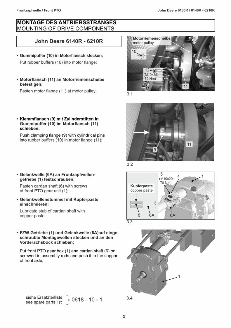
• Gelenkwelle (6A) an Frontzapfwellen-getriebe (1) festschrauben;
Fasten cardan shaft (6) with screws at front PTO gear unit (1);
• Gelenkwellenstummel mit Kupferpasteeinschmieren;
Lubricate stub of cardan shaft with copper paste;
3.3
6A
14 5(M10x20: 70 Nm)
6A8
Kupferpastecopper paste
• FZW-Getriebe (1) auf einge-schraubte Montagewellen stecken und an denVorderachsbock schieben;
und Gelenkwelle (6A)
Put front PTO gear box (1) and cardan shaft (6) on screwed-in assembly rods and push it to the support
of front axle;
3.4
1
John Deere 6140R - 6210R
0618 - 10 - 1siehe Ersatzteillistesee spare parts list
•Gummipuffer (10) Motorflansch (11)
rubber buffers (10) in motor flange (11);
Klemmflansch (9) mit Zylinderstiften inim
schieben;
Push clamping flange (9) with cylindrical pinsinto
• Gummipuffer (10) in Motorflansch stecken;
Put rubber buffers (10) into motor flange;
• Motorflansch (11) an Motorriemenscheibebefestigen;
Fasten motor flange (11) at motor pulley;
MONTAGE DES ANTRIEBSSTRANGESMOUNTING OF DRIVE COMPONENTS
3.2
11
9
3.1
11
12(M10x25: 70 Nm)
10
Motorriemenscheibemotor pulley
4
Frontzapfwelle / Front PTO John Deere 6130R / 6140R - 6210R
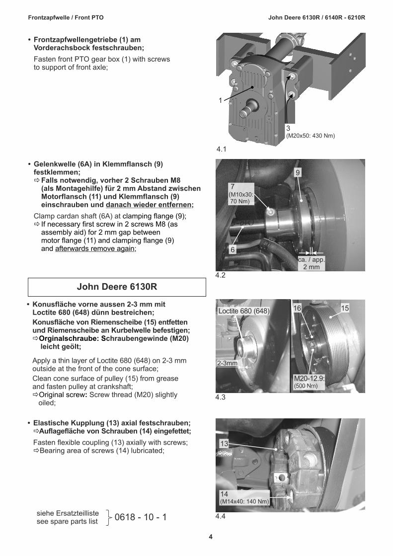
• Frontzapfwellengetriebe (1) am Vorderachsbock festschrauben;
Fasten front PTO gear box (1) with screwsto support of front axle;
4.1
3(M20x50: 430 Nm)
1
0618 - 10 - 1siehe Ersatzteillistesee spare parts list
4.2
ca. / app.2 mm
7(M10x30: 70 Nm)
9
6
• Gelenkwelle (6A) in Klemmflansch (9) festklemmen;
Falls notwendig, vorher 2 Schrauben M8(als Montagehilfe) für 2 mm Abstand zwischenMotorflansch (11) und Klemmflansch (9) einschrauben und danach wieder entfernen;
Clamp cardan shaft (6A) at
ð
clamping flange (9);ð If necessary first screw in 2 screws M8 (as
assembly aid) for 2 mm gap between motor flange (11) and clamping flange (9) and afterwards remove again;
John Deere 6130R
• Konusfläche vorne aussen 2-3 mm mit Loctite 680 (648) dünn bestreichen;
Konusfläche von Riemenscheibe (15) entfettenund Riemenscheibe an Kurbelwelle befestigen;
chraubengewinde (M20) leicht geölt;
Apply a thin layer of Loctite 680 (648) on 2-3 mmoutside at the front of the cone surface;
Clean cone surface of pulley (15) from greaseand fasten pulley at crankshaft;
Screw thread (M20) slightly oiled;
ðOrginalschraube: S
ðOriginal screw: 4.3
M20-12.9:(500 Nm)
16 15
2-3mm
Loctite 680 (648)
• Elastische Kupplung (13) axial festschrauben;Auflagefläche von Schrauben (14) eingefettet;
Fasten flexible coupling (13) axially with screws;Bearing area of screws (14) lubricated;
ð
ð
4.4
14(M14x40: 140 Nm)
13
5
Frontzapfwelle / Front PTO John Deere 6130R / 6140R - 6210R
• Schutztopf (2) nach Montage aller Anbauteile an Frontzapfwellengetriebe (1)festschrauben;
Fasten protecting funnel (2) with to front PTO gear box (1) after mounting of all mounting parts;
screws
0618 - 10 - 10618 - 20 - 1 -2*
siehe Ersatzteillistesee spare parts list
• Gelenkwelle (6B) an Frontzapfwellen-getriebe (1) festschrauben;
Fasten cardan shaft (6B) with screws at front PTO gear unit (1);
5.2 6B
14 5(M10x20: 70 Nm)
• Gelenkwelle (6B) auseinanderziehen,hinteren Teil der Gelenkwelle von vorne ein-schieben,Gelenkwelle (6B) mit elastischerKupplung (9) verschrauben;(Auflagefläche von Schrauben (10) eingefettet);
Pull apart cardan shaft (6B), push in rear part of the cardan shaft from the front,Screw cardan shaft (6B) to flexible coupling (13);
(Bearing area of screws (14) lubricated)
• FZW-Getriebe (1) auf eingeschraubteMontagewellen stecken und zum Vorder-achsbock schieben, dabei Gelenkwelle (6B)unter Kühler einschieben und zusammenstecken;
Put front PTO gear box (1) on screwed-inassembly rods and push it to the support of frontaxle, pushing cardan shaft (6B) in below cooler and assemble;
5.1
136B
14(M14x40: 140 Nm)
Check if there is enough space for rotating parts!
Freiräume für drehende Teile kontrollieren!!
• Adeckung (17) montieren;
Mount shield (17); 17
5.4
5.3
1
5.5
M8x20
241*40*42*43*1
6
Frontzapfwelle / Front PTO John Deere 6130R / 6140R - 6210R
0618 - 80 - 1siehe Ersatzteillistesee spare parts list
• FZW-Schalter (1) einbauen:Connect switch (1):
MONTAGE DER FZW-ELEKTRIKMOUNTING OF ELECTRICAL PARTS OF FRONT PTO
• Durchgangsloch für Kabeldurchführung in Haubenabschlussblech bohren (Ø 10 mm);
Drill a trough hole for cable feedtrough into endcover plate hood (Ø 10 mm);
• FZW-Kabel (2) durchführen, Gummitülle (3) ein-bauen;
Put trough PTO cable (2), mount rubber bushing (3);
• Bearbeitete Teile gegen Korrosion schützen;
Protect processed parts against corrosion ;
6.2
• Einzelleiter in Stiftgehäuse (2.1) einführen und mitKlemmstück (2.2) sichern;
Enter single conductor into pin housing (2.1) and
secure with clamp piece (2.2);
6.3
ABCD
braunbrown
schwarz/weißblack/white
lilapink
schwarzblack
rechte Schaltkonsoleright control panel
X127(vorhandener Stecker)(available pin)
1Command Arm
6.1
7
Frontzapfwelle / Front PTO John Deere 6130R / 6140R - 6210R
0618 - 80 - 1siehe Ersatzteillistesee spare parts list
Anschlussplan für FZW-ElektrikWiring scheme for front PTO-electical parts
FZW-Getriebefront PTO gear unit
•
Lay and connect front PTO cable (2):
FZW-Kabel (2) verlegen und anschliessen:
310 sc
hw
arz
/ b
lack
607 lil
a / p
ink
531 sc
hw
.-w
s. / b
l.-w
h
301 bra
un / b
row
n
DCBA
X02
AB
speed sensorDrehzahlsensor
solenoid valveMagnetventil
973 ora
nge / o
range
901 bra
un / b
row
n
904 gelb
/ y
ello
w
ABC X127X127
switchFZW-Schalter
7.1
Secure front PTO cable with cable fixers to exclude following risks:• chafing • squeezing • influence of heat !
Sichern Sie das Frontzapfwellenkabel mit Kabelbindern gegen folgendeGefahrenquellen: • Scheuern • Einquetschen • Hitzeeinwirkung !
!
8
Frontzapfwelle / Front PTO John Deere 6130R / 6140R - 6210R
All instruction sticker have to be affixed in sight of the user.Before affixing spring-clean surface area.
Sämtliche Hinweis-Aufkleber sind für den Anwender sichtbar anzubringen.Vor dem Aufkleben Oberfläche gründlich reinigen.
!
POST-ASSEMBLY CHECK AFTER MOUNTING THE COMPLETE FRONT PTO:
Ÿ If the motor is stopped while the front PTO is running and then restarted, the front PTO won’tstart anymore.
ð Switch the front PTO off and on again !
ŸSwitch front PTO on and off 10 times with engine running and check the function !
ðIf any function is not working, error must be eliminated by an expert.Otherwise an accident may occur!
KONTROLLE NACH ANBAU DER KOMPLETTEN FRONTZAPFWELLE:
ŸWird bei laufender Frontzapfwelle der Motor abgestellt und anschliessend wieder gestartet,so läuft die Frontzapfwelle nicht wieder an.
ð Schalten Sie die Frontzapfwelle aus und wieder ein !
ŸSchalten Sie bei laufendem Motor die Frontzapfwelle 10 mal ein und aus und prüfen Sie dieFunktion !
ðFalls diese Funktionen nicht erreicht werden, muss die Fehlerursache fachgerechtbehoben werden, sonst droht Unfallgefahr!
Sauter GmbHD-87778 StettenTel.: ++49 (82 61) 7 59 94 - 0Fax:++49 (82 61) 7 59 94 - 20
Front PTOFrontzapfwelle
Spare parts listErsatzteilliste
(mit HZ-Getriebe)
(with gear unit series HZ)
Nr. / No.: 006-0618
JOHN DEERE
6130R6140R - 6150R6170R - 6210R
Ersatzteilliste: Antriebsstrang 0618 - 10 - 1
Spare parts list: Drive components
John Deere 6130R / 6140R - 6150R / 6170R - 6210R Stand: Update: 07.12
Pos. No.
Menge Quant.
Teile-Nr. No. of part
Bezeichnung Designation Norm / Abmessung Standard / Dimension
01 1 Frontzapfwellengetriebe front PTO gear box ð 612-0063-04 HZB, i = 1,93 ð 612-0064-02 HZE, i = 1,63 02 1 020-053300 FZW-Schutztopf protecting funnel 03 4 100-1175 Innensechskantschraube hexagon socket screw DIN 912-M20x50-8.8 - 391 Nm 04 4 200-1102 Sicherungsscheibe locking washer Schnorr-VS10 05 4 100-1602 Innensechskantschraube hexagon socket screw DIN 912-M10x20-10.9-70 Nm 06 A 010-088700 Gelenkwelle cardan shaft 07 1 100-1604 Innensechskantschraube hexagon socket screw DIN 912-M10x30-10.9-70 Nm 08 1 101-0858 Paßfeder adjusting spring DIN 6885 – A10x8x63 09 1 610-0059 Klemmflansch kpl. clamping flange cpl. 10 8 200-0202 Gummipuffer rubber buffer 11 1 010-305100 Motorflansch kpl. motor flange cpl. 12 4 100-1603 Innensechskantschraube hexagon socket screw DIN 912-M10x25-10.9-70 Nm 17 1 050-307400 Abdeckblech Cover sheet
John Deere 6130 R 06 B 010-086300 Gelenkwelle cardan shaft 13 1 200-0103 Elastische Kupplung flexible coupling Centraflex Gr.28 14 8 200-0602 Innensechskantschraube hexagon socket screw DIN 912-M14x40-8.8-140 Nm 15 1 010-206200 Riemenscheibe kompl. pulley 16 1 010-206300 Scheibe washer DIN1013-Rd 70x19
Ersatzteilliste: Frontzapfwellengetriebe (HZB) 0618 - 20 – 1 1 Spare parts list: Front PTO gear unit (HZB)
John Deere 6130R / 6140R - 6150R / 6170R - 6210R Stand: Update: 01.12
Pos. No.
Menge Quant.
Teile-Nr. No. of part
Bezeichnung Designation Norm / Abmessung Standard / Dimension
01 1 020-204700 Getriebegehäuse gear housing 02 1 020-015000 Getriebedeckel cover 03 1 020-029400 Ritzelwelle pinion shaft
04 1 200-8028 Hydraulik-Lamellenkupplung (bestehend aus Pos. 04 A-W)
hyraulic multiple disc clutch (consisting of nos. 04 A-W)
04 A 1 200-8101 Belagscheibe disc 04 B 2 200-2050 Kugellager bearing 16011 04 C 8 200-0289 Außenlamelle outer disc 04 D 7 200-0290 Innenlamelle inner disc 04 E 1 200-8029 Topf mit Zahnrad housing with gear wheel 04 F 1 200-8007 Keilwelle shaft 04 G 1 200-8025 Kolben piston 04 H 1 200-8010 Zylinder cylinder 04 J 1 200-8003 Scheibe washer 04 K 1 200-8005 Scheibe washer 04 L 1 200-8006 Scheibe washer 04 M 1 200-3620 Scheibe washer 04 N 6 200-0422 Druckfeder spring 1,8x9,1x40,5 04 P 6 200-0417 Druckfeder spring 1,0x5,1x41,3 04 R 1 100-0665 Sicherungsring snap ring DIN 471 - 40x1,75 04 S 1 100-0680 Sicherungsring snap ring DIN 471 - 80x2,5 04 T 1 100-0725 Sicherungsring snap ring DIN 472 - 90x3 04 U 1 205-0670 O-Ring gasket 35x2 04 V 1 202-0602 Quadring gasket 4219 04 W 1 202-0604 Quadring gasket 4245
05 1 611-6016 Pumpeneinheit (bestehend aus Pos. 05 A-H)
Pump unit (consisting of nos. 05 A-H)
05 A 1 611-6017 Pumpenkolben mit Lager piston with bearing 05 B 1 010-150900 Pumpengehäuse housing 05 C 2 205-0668 O-Ring gasket 32x2,5 05 D 1 010-151100 Zapfen pin 05 E 1 200-0412 Druckfeder spring 2,6x15,9x41 05 F 1 200-2500 Stahlkugel steel ball Ø8 05 G 1 200-0411 Druckfeder spring 0,63x6,3x17 05 H 1 060-066000 Ventilschraube screw
06 1 200-2003 Kugellager bearing 6208-C3 07 2 200-2704 Wellendichtring shaft seal 45x60x7 08 2 200-2009 Kugellager bearing 6309-C3 09 1 200-2077 Kugellager bearing 6209-C3 10 1 010-160500 Rohr tube l=27 11 1 205-0651 O-Ring gasket 10x2 12 4 100-0904 Innensechskantschraube hexagon socket screw DIN 912-M6x30 - 8.8 - 10 Nm 13 4 101-2950 Scheibe washer DIN 7349-6,4x17x3 14 4 200-0416 Druckfeder spring 1,6x15,4x28,7 15 1 020-051700 Trennblech separating sheet 16 10 100-0959 Innensechskantschraube hexagon socket screw DIN 912-M8x50 - 8.8 - 25 Nm 17 3 100-0953 Innensechskantschraube hexagon socket screw DIN 912-M8x20 - 8.8 - 25 Nm 18 3 101-0201 Zylinderstift cylindrical pin DIN 6325-8x20-A 19 1 611-6008 Steuerkolben mit Dichtung piston-valve with gasket 20 1 010-150700 Federführung pin 21 1 200-0409 Druckfeder spring 5,5x20x100 22 1 200-0410 Druckfeder spring 6x33x140 24 1 010-307800 Getriebeflansch flange 25 1 101-0858 Passfeder adjusting spring DIN 6885 - 10x8x63 26 1 010-027200 Scheibe washer 40x8x13 27 1 100-3803 Sechskantschraube hexagon bolt DIN 933-M12x70 - 8.8 - 80 Nm
Ersatzteilliste: Frontzapfwellengetriebe (HZB) 0618 - 20 - 2 2 Spare parts list: Front PTO gear unit (HZB)
John Deere 6130R / 6140R - 6150R / 6170R - 6210R Stand: Update: 07.12
Pos. No.
Menge Quant.
Teile-Nr. No. of part
Bezeichnung Designation Norm / Abmessung Standard / Dimension
28 1 202-0171 Magnetspule solenoid coil 29 1 202-0170 Magnetventil solenoid valve 30 1 205-0520 Kupferring sealing DIN 7603 – 30x36x2 31 1 202-0190 Ölfilter oil filter 32 1 020-015700 Abdeckblech cover sheet 33 1 100-0900 Innensechskantschraube hexagon socket screw DIN 912-M6x10 - 8.8 - 10 Nm 34 1 200-3502 Entlüftungsventil air-vent valve M18x1,5 35 1 100-0750 Verschlußschraube drain plug DIN 908-M10x1,0-5.8 36 1 205-0505 Kupferring sealing DIN 7603 - 10x14x1 37 2 100-0754 Verschlußschraube drain plug DIN 908-M18x1,5-5.8 38 1 100-0755 Verschlußschraube mit Magnet drain plug with solenoid DIN 908-M18x1,5-5.8 39 3 205-0515 Kupferring sealing DIN 7603 - 18x24x1,5 40 1 020-015500 Schutzring fastening ring 41 1 200-2905 Zapfwellenschutz PTO guard 42 2 100-4352 Sechskantschraube hexagon bolt DIN 933-M8x20 - 8.8 - 25 Nm 43 2 100-0504 Scheibe washer DIN 125-8,4x16x1,6 44 1 211-5500 Kabelhalter cable clip Ø6 45 1 100-0001 Zylinderschraube hexagon socket screw DIN 84-M4x10 - 4.8 46 1 214-0211 Drehzahlsensor speed sensor
60 1 610-9004 Dichtsatz für Getriebe (bestehend aus Pos. 05 C, 7, 11, 30, 36, 39)
seal kit gear unit (consisting of nos. 05 C, 7, 11, 30, 36,39)
Ersatzteilliste: Frontzapfwellengetriebe (HZE) 0618 - 20 – 2 1 Spare parts list: Front PTO gear unit (HZE)
John Deere 6130R / 6140R - 6150R / 6170R - 6210R Stand: Update: 01.12
Pos. No.
Menge Quant.
Teile-Nr. No. of part
Bezeichnung Designation Norm / Abmessung Standard / Dimension
01 1 020-204800 Getriebegehäuse gear housing 02 1 020-202000 Getriebedeckel cover 03 1 020-029800 Ritzelwelle pinion shaft
04 1 200-8030 Hydraulik-Lamellenkupplung (bestehend aus Pos. 04 A-X)
hyraulic multiple disc clutch (consisting of nos. 04 A-X)
04 A 1 200-8101 Belagscheibe disc 04 B 2 200-2050 Kugellager bearing 16011 04 C 6 200-0289 Außenlamelle outer disc 04 D 5 200-0290 Innenlamelle inner disc 04 E 1 200-8031 Zahnradtopf housing with gear wheel 04 F 1 200-8007 Keilwelle shaft 04 G 1 200-8025 Kolben piston 04 H 1 200-8010 Zylinder cylinder 04 J 1 200-8003 Scheibe washer 04 K 1 200-8005 Scheibe washer 04 L 1 200-8006 Scheibe washer 04 M 1 200-3620 Scheibe washer 04 N 6 200-0422 Druckfeder spring 1,8x9,1x40,5 04 P 6 200-0417 Druckfeder spring 1,0x5,1x41,3 04 R 1 100-0665 Sicherungsring snap ring DIN 471 – 40x1,75 04 S 1 100-0680 Sicherungsring snap ring DIN 471 – 80x2,5 04 T 1 100-0725 Sicherungsring snap ring DIN 472 – 90x3 04 U 1 205-0670 O-Ring gasket 35x2 04 V 1 202-0602 Quadring gasket 4219 04 W 1 202-0604 Quadring gasket 4245
05 1 611-6016 Pumpeneinheit (bestehend aus Pos. 05 A-H)
Pump unit (consisting of nos. 05 A-H)
05 A 1 611-6017 Pumpenkolben mit Lager piston with bearing 05 B 1 010-150900 Pumpengehäuse housing 05 C 2 205-0668 O-Ring gasket 32x2,5 05 D 1 010-151100 Zapfen pin 05 E 1 200-0412 Druckfeder spring 2,6x15,9x41 05 F 1 200-2500 Stahlkugel steel ball Ø8 05 G 1 200-0411 Druckfeder spring 0,63x6,3x17 05 H 1 060-066000 Ventilschraube screw
06 1 200-2003 Kugellager bearing 6208-C3 07 2 200-2704 Wellendichtring shaft seal 45x60x7 08 2 200-2009 Kugellager bearing 6309-C3 09 1 200-2077 Kugellager bearing 6209-C3 10 1 010-160500 Rohr tube l=27 11 1 205-0651 O-Ring gasket 10x2 12 4 100-0904 Innensechskantschraube hexagon socket screw DIN 912-M6x30 – 8.8 – 10 Nm 13 4 101-2950 Scheibe washer DIN 7349-6,4x17x3 14 4 200-0416 Druckfeder spring 1,6x15,4x28,7 15 1 020-051700 Trennblech separating sheet 16 10 100-0959 Innensechskantschraube hexagon socket screw DIN 912-M8x50 – 8.8 – 25 Nm 17 3 100-0953 Innensechskantschraube hexagon socket screw DIN 912-M8x20 – 8.8 – 25 Nm 18 3 101-0201 Zylinderstift cylindrical pin DIN 6325-8x20-A 19 1 611-6008 Steuerkolben mit Dichtung piston-valve with gasket 20 1 010-150700 Federführung pin 21 1 200-0409 Druckfeder spring 5,5x20x100 22 1 200-0410 Druckfeder spring 6x33x140 23 020-028800 Zahnkranz toothed wheel 24 1 010-307800 Getriebeflansch flange 25 1 101-0858 Passfeder adjusting spring DIN 6885 – 10x8x63 26 1 010-027200 Scheibe washer 40x8x13 27 1 100-3803 Sechskantschraube hexagon bolt DIN 933-M12x70 – 8.8 – 80 Nm 27.1 12 100-2254 Innensechskantschraube hexagon socket screw DIN 912-M8x25-12.9-45 Nm
Ersatzteilliste: Frontzapfwellengetriebe (HZE) 0618 - 20 - 2 2 Spare parts list: Front PTO gear unit (HZE)
John Deere 6130R / 6140R - 6150R / 6170R - 6210R Stand: Update: 07.12
Pos. No.
Menge Quant.
Teile-Nr. No. of part
Bezeichnung Designation Norm / Abmessung Standard / Dimension
28 1 202-0171 Magnetspule solenoid coil 29 1 202-0170 Magnetventil solenoid valve 30 1 205-0520 Kupferring sealing DIN 7603 – 30x36x2 31 1 202-0190 Ölfilter oil filter 32 1 020-015700 Abdeckblech cover sheet 33 1 100-0900 Innensechskantschraube hexagon socket screw DIN 912-M6x10 - 8.8 - 10 Nm 34 1 200-3502 Entlüftungsventil air-vent valve M18x1,5 35 1 100-0750 Verschlußschraube drain plug DIN 908-M10x1,0-5.8 36 1 205-0505 Kupferring sealing DIN 7603 - 10x14x1 37 2 100-0754 Verschlußschraube drain plug DIN 908-M18x1,5-5.8 38 1 100-0755 Verschlußschraube mit Magnet drain plug with solenoid DIN 908-M18x1,5-5.8 39 3 205-0515 Kupferring sealing DIN 7603 - 18x24x1,5 40 1 020-015500 Schutzring fastening ring 41 1 200-2905 Zapfwellenschutz PTO guard 42 2 100-4352 Sechskantschraube hexagon bolt DIN 933-M8x20 - 8.8 - 25 Nm 43 2 100-0504 Scheibe washer DIN 125-8,4x16x1,6 44 1 211-5500 Kabelhalter cable clip Ø6 45 1 100-0001 Zylinderschraube hexagon socket screw DIN 84-M4x10 - 4.8 46 1 214-0211 Drehzahlsensor speed sensor
60 1 610-9004 Dichtsatz für Getriebe (bestehend aus Pos. 05 C, 7, 11, 30, 36, 39)
seal kit gear unit (consisting of nos. 05 C, 7, 11, 30, 36,39)
Ersatzteilliste FZW-Elektrik 0618 - 80 - 1
Spare parts list Front PTO electrical parts
John Deere 6130R / 6140R - 6150R / 6170R - 6210R Stand/ Update: 01.12
Pos. No.
Menge Quant.
Teile-Nr. No. of part
Bezeichnung Designation Norm / Abmessung Standard / Dimension
01 1 211-5248 FZW-Schalter switch
02 1 616-10170 Kabelstrang loom of cables
2.1 1 211-0641 Stiftgehäuse pin housing
2.2 1 211-0642 Klemmstück clamp
03 1 211-0500 Gummitülle rubber bushing
12
2.1 2.2
3