50
Montageanleitung Assembly instructions CURTAIN-SIDER-VERDECK · CURTAIN-SIDER ROOF DE|EN 2016 | 09 Standard Volumen Universal Classic

MontageanleitungAssembly instructions
CURTAIN-SIDER-VERDECK · CURTAIN-SIDER ROOF
DE|EN 2016 | 09
Standard Volumen Universal Classic

Inhaltsangabe Contents
DE EN
2
Meaning of symbols 3
Introduction to CS - SLIMLINER St/V 2014 4
5
Montage
Bestimmungsgemäße Verwendung 5 Designated use
Assembly
Maximal zulässige Spurabweichung 6
Systembreite / Spurweite 7
Aluprofil Montagesatz Front-Heck / Standard 8
Aluprofil Montagesatz Front-Heck / Volumen 10
Aluprofil Montagesatz Front-Heck / Universal Classic 12
Ausklinkschema für Hubdach 14
Spriegelaufteilung-Schema 15
Vormontierte Spriegel - definierte Reihenfolge 16
Montage Portalbalken am Endlaufwagen 17
Endlaufwagen aufschieben 18
Montage Faltplatte - Endlaufwagen / Spriegel 19
Montage Verriegelung Heck / Verschleißauflage 21
Ermitteln der Dachpaketlänge zzgl. Zugabe 23
Montage Rampe Front 24
Montage Stirnwandseile / Seilspannung 25
Dichtungen einschieben 27
4-Seil-Dachaussteifung 28
Montage Seiladapter Front / Seilanbindung Front 29
Montage Seilanbindung Montagesatz Front 31
Seilanbindung Portalbalken Heck 32
Montage Seiladapter Mitte / Seilanbindung Mitte 33
Überprüfung der Seilspannung mittels Zugstange 35
Einstellung der Seilspannung 36
Montage Expanderseile 37
Dachplanenbefestigungspunkte 38
Dachplanenbefestigungspunkte / DB 39
Planenverlauf Spriegel 40
Montage TIR Heck / Maxlock / TIR Front 41
Vorgaben zur Konfektionierung der Seitenplane 45
Vorgaben zur Befestigung der Seitenplane 46
Dachplanenbefestigung Stirnwand 47
Planenbefestigung am Portalbalken 48
Maximum permissible rail deviation 6
System width / track width 7
Aluminium profile front/rear installation set - Standard 8
Aluminium profile front/rear installation set -Volume 10
Aluminium profile front/rear installation set - Universal Classic 12
Release scheme for lifting roof 14
Bow distribution scheme 15
Pre-assembled bows - defined sequence 16
Installing the gantry beam on the end carriage 17
Installing the end carriage 18
Installing the hinge - end carriage / bow 19
Installing the rear lock / plastic surface 21
Determination of the roof package length plus addition 23
Installing the front ramp 24
Installing the front rope / Cable tension 25
Inserting the sealing 27
4-cable roof reinforcement 28
Installing the rope adapter front / Cable connection 29
Installing cable connection installation set front 31
Cable connection gantry beam rear 32
Installing the rope adapter / Cable connection Centre 33
Checking the cable tension using a tension rod 35
Setting the cable tension 36
Installing the expander cables 37
Roof plan attachment points 38
Roof plan attachment points / DB 39
Securing the cover to the bow 40
Installing TIR - Rear / Maxlock / TIR Front 41
Requirements for configuring the side curtain 45
Requirements for attaching the side curtain 46
Securing the roof cover to the rear wall 47
Securing the cover to the gantry beam 48
Symbolerklärungen 3
Einleitung CS - SLIMLINER St/V 2014 4
Typidentifizierung 49 Type identification 49

3
Symbolerklärungen · Meaning of SymbolsSymbolerklärungen · Meaning of Symbols
MaulschlüsselFork spanner
InbusschlüsselAllen key
Bestimmungsgemäße Verwendung Intended usage
Montage Assembly
Typidentifizierung Type identification
Kanten entgraten Deburring edges
InhaltsangabeContents
ErklärungMeaning
?
Nietenzange Riveting tool
Schmierseife Soft soap
Bohrmaschine Drill
DE EN
SchweißgerätWelding equipment
Unbedingt beachten! Please note without fail!
Klickgeräusch Hörbares Einrasten Clicking soundSnaps in audibly
!
Seilführung über / unter SpriegelRope over / under bows
Portalbalken schließenClose gantry beam
St
UC
V
Standard Standard
Universal Classic Universal Classic
Volumen Volume
TailWing Maße abweichendTailWing deviating dimensions
Kabelbinder Cable strap
Vorgang beidseitig ausführen Carry out process on both sides

?
4
DE EN
1.
2.
3.
4.
5.
6.
a
b
c
Einleitung CS - Slimliner St/V 2014 Introduction CS - Slimliner St/V 2014
Das CS - Slimliner Verdeck wurde so konzipiert, dass es bei sachgemäßer Montage einen sehr hohen Komfort sowohl beim Öffnen als auch beim Schließen bietet.
Die Anleitung hat für alle Modellvarianten des Slimliner - Verdeckes Gültigkeit. Es kann also durchaus vorkommen, dass ein-zelne Passagen nicht auf Ihr Verdeck zutreffen.
Erklärungen:
Endlaufwagen Portalbalken Spriegel mit Rollenwagen Faltplatte Laufschiene Seilanbindung - Stirnwand Front Heck Fahrtrichtung
The CS - Slimliner - roof was designed in such a manner as to offer a high level of comfort for the opening and closing process when properly handled and maintened.
The instructions are valid for all model variants of the Slimliner roof. It can thus happen that individual passages do not apply to your roof-variant.
Explanations:
End carriage Gantry beam Bow with roller carriage Hinge Running rail Cable connection - bulkhead Front Rear Driving direction
1. 1.
2. 2.
3. 3.
4. 4.
5. 5.
6. 6.
a a
b b
c c

?
5
Jegliche Haftung des Herstellers European Trailer Systems GmbH erlischt, wenn:
• das Sesam Schiebeverdeck sowie dessen Bauteile eigenmächtig verändert werden;• Sesam-Originalteile gegen andere Bauteile ausgewechselt werden• das Sesam Schiebeverdeck sowie dessen Bedienungsbau- teile nicht nach den gültigen Sesam Richtlinien bedient und gewartet werden
Alle hieraus resultierenden Risiken und Haftungs-ausschlüsse bestehen auch dann, wenn:
• Abnahmen durch Prüfer oder durch Sachverständige der technischen Prüfstellen oder durch Sachverständige amtlich anerkannter Organisationen erfolgt sind;• behördliche Genehmigungen vorliegen.
© 2016 European Trailer Systems GmbHwww.EdschaTS.com
• 1a 1b Vor Antritt der Fahrt von Dachlasten befreien
• 2 . Dachlast ≤ 75 kg / m2
• 3. Nicht begehbar
The manufacturer, European Trailer Systems GmbH, is discharged from any liability if:
• the Sesam sliding roof and its components are changed arbi-trarily
• Sesam original parts are exchanged against other components;
• the Sesam sliding roof and its operating components are not handled and serviced in compliance with the prevailing Sesam instructions
All the arising exclusions of risk and liability shall remain valid also if:
• examiners or experts of the technical testing bodies or experts from officially recognised organisations have performed acceptance tests;• official approval exists.
© 2016 European Trailer Systems GmbHwww.EdschaTS.com
• 1a 1b Remove roof loads before starting a trip
• 2 . Roof load ≤ 75 kg / m2
• 3. Cannot be walked on
EN
DE
Der Fahrzeugausrüster ist grundsätzlich verpflichtet zu prüfen, ob die dargestellten Produkte den Anforderungen des Anwenders genügen.
The vehicle equipment supplier is obligated in principle to check whether the products shown satisfy the demands of the user.
!
!
!
!
!
!
!
!
!
!
The Sesam sliding roofs and their operating components are exclusi-vely manufactured for their due employment on truck specific transport operations. Any usage going beyond such applications is considered as misuse. For resulting damages the manufacturer European Trailer Systems GmbH repudiates any liability; for this the user alone bears the full risk. The “intended usage” also includes the observance of the operation, care and maintenance instructions and of the mounting and repair instructions as prescribed by the manufacturer.
Die Sesam Schiebeverdecke und deren Bedienungsbauteile sind ausschließlich für den vorschriftsmäßigen Einsatz bei lastwagenspe-zifischen Transporteinsätzen gefertigt. Jeder darüber hinausgehende Gebrauch gilt als nicht bestimmungsgemäß. Für hieraus resultierende Schäden lehnt der Hersteller European Trailer Systems GmbH jegli-che Haftung ab, Risiken hierzu trägt allein der Benutzer. Zur bestim-mungsgemäßen Verwendung gehört auch die Einhaltung der vom Hersteller vorgeschriebenen Bedienungs-, Wartungs- und Pflegean-weisungen, sowie die Montage- und Reparaturanleitung.
≤ 75 kg / m21a 2. 3.1b

?
6
2014 wurde eine zweite Generation des Slimliner-Verdecks eingeführt. Diese definiert sich über die Spurweite Z.
Die max. zulässige Winkelabweichung der Profilstellung darf ± 3° betragen. Die Stirn- und Heckanbindungskonstruktionen müs-sen in der Lage sein, ein Drehmoment von 750Nm übertragen zu können.
A second generation of the Slimliner roofs was introduced in 2014. This is defined by the track gauge Z.
The maximum permissible angle deviation on the profile setting is ± 3°. The bulkhead and rear connection structures must be able to transfer torque of 750 Nm.
X
X
1
2
4
3
1- 4
+/- ~2mm
+/- ~2mm
St
UC UC
StV V
Maximal zulässige Spurabweichung /Aufbautoleranz
Maximum permissible rail deviation / construction tolerance
+/- 30 mm
St V
3° 3° 3°3°
± 3° (MD = 750 Nm)
UC
3°3°
DE EN
1

?
7
St
V
UC
X (2550 mm)
X (2550 mm)
System width/track widthSystembreite/Spurweite
Z
Z
Z
Z = Spurweite X = Systembreite
Z = Track widthX = System width
X (2550 mm)
DE EN
2

?
8
St
!
Aluprofil Montagesatz Front montieren - Standard
*Nieten als Alternative
Aluminium profile installation set front - Standard
*Rivet as alternative
16/15611
Seite 6 • Page 6
*
DE EN
3

?
9
St
Aluprofil Montagesatz Heck montieren - Standard
Aluminium profile installation set rear - Standard
811 6
DE EN
4

?
10
Aluprofil Montagesatz Front montieren - Volumen
*Nieten als Alternative
Aluminium profile installation set front - Volume
*Rivet as alternative
V!Seite 6 • Page 6
16/15611
*
24
DE EN
5

?
11
Aluprofil Montagesatz Heck montieren - Volumen
Aluminium profile installation set rear - Volume
V
5119 13
DE EN
6

?
12
V
Ausklink-Schema für Hubdach
Release scheme for lifting roof
3-D ( 1 : 2 )
für Profil / for profile6 900 301 0 ( 1 : 2 )
Stückliste / parts listGewicht / weightBenennung / titleMaterial Nr. / material No.Zeichnungs Nr. / drawing No.Menge / quantityPosition0,012 kgSenkkopfschraube / countersunk head screw ISO 10642 - M8 x 25 - 8.8 zinc coated1005682o. Z.470,055 kgKlemmleiste VG / terminal block cg6 900 213 0900213260,036 kgSkt.-Schraube / hex bolt ISO 4017 - M10 x 40 - 8.8 zinc coated3 807 819 0o. Z.650,204 kgKlemmleiste VG / terminal block cg3 807 784 0807784240,252 kgStützblech / support plate3 808 136 0808136231,498 kgZ-Profil rechts für CS-Volumenprofil / Z-profile right for CS-volume profile6 900 212 0900211121,498 kgZ-Profil links für CS-Volumenprofil / Z-profile left for CS-volume profile6 900 211 090021111
1
1
2
2
3
3
4
4
5
5
6
6
7
7
8
8
9
9
10
10
11
11
12
12
A A
B B
C C
D D
E E
F F
G G
H H
Aenderungsmitteilung
Truck Equipment GmbH
Zchng. -Nr.Spiegelbild/Drwg. No.mirror image
Characteristic to be documented
circa/approx.Gewicht/Weight
Sicherheits-Dok.Safety doc.
Status
Mat.-Nr.Spiegelb./Mat.No.mirror image
Material-Nr./Material No.
Projection:ISO 128-30 Massstab/Scale Benennung/Title
Zchnungs -Nr./Drawing No.
Oberflaechenbehandlung/Surface treatment
Waermebehandlung/Heat treatment
Massnorm/Dimension standard
Document change date
Werkstoff/Material
Oberflaechen nach/Surface to
Dokumentationspflichtiges Merkmal
Funktions- und PruefmasseFunctional- and test dimensions
All dimension apply to finishedpart after surface treatment.
nach der Oberflaechenbehandlung.Alle Maße gelten fuer das Fertigteil
Werkstueckkanten/Edge finish
Therm.Schneiden/Therm.cutGussmasse/Cast dimensionSchmiedemasse/Forged dim.Stanzmasse/Stamped dim.
dimensions for welding constructions:Allowable deviations on untoleranced
Genauigkeitsgrad/Precision grade
Guete/Class
Winkel/Angle
::
:
::
::
Erstellt/Designed
VBG GROUP
Geändert/Revised
von/of
oZFormat/Size
the use of
(specifieddocuments
Blatt/Sheet
change Drawingwith CAD only
aendern
ISO 16016)
Zeichnung nurüber CAD
in
regarding
beachten
restriction
SchutzvermerkISO 16016
Geprüft/Checked
Note
Plot ist aus dem Archiv:Plot is from file:
Revision recordBeschreibung der AenderungAllowable deviations on untoleranced dim.
Zulaessige Abweichung fuer nichttolerierte Masse von Schweisskonstruktionen:
Zul. Abweichung fuer untolerierte MasseSize of fitPassmass
upper loweroberes unteres
Section
Version
FeldVersion
Montagesatz CS-Volumenprofil hintenmounting kit CS-volume profile rear
6 900 008 0
1:2
05.03.2015
Weigelt
25.07.2013
Weigelt
05.03.2015
A.Scholz
c11492
ISO 2768
4,4 kg
ISO 1302
DIN 2310
ISO 13715
EN ISO 13920-BF+/ -1°DIN 6930
SF
Trailer Systems
900008
1
A1
1
Edscha
Freigegeben/Released
Montagesatz hinten linksmounting kit rear left
Montagesatz hinten rechtsmounting kit rear right
beim Kunden geschweißtwelded by customer
2
3
44
Aufbaubreite / body width (2550)
c - drawing revisedc - Zeichnung überarbeitetc - release for productionc - Serienfreigabe
6
4
57
1 2
(19,5)15,5
110
max
. R16
75
102,
5
250
10x45°
45 70 70
� 9 im Profil bohren� 9 to drill in profile
ØØ
9 im Profil bohren
9 to drill in profil
DE EN
9

?
13
UC
Aluprofil Montagesatz Front montieren - Standard
Aluminium profile installation set front - Standard
16/15611
Seite 6 • Page 6 !
DE EN
7

?
14
UC
Aluprofil Montagesatz Heck montieren - Standard
Aluminium profile installation set rear - Standard
11
DE EN
8

?
15
Spriegelaufteilung-Schema
Spriegelaufteilung / Bow distribution
Dach / Roof 18x692
gerade Spriegelanzahl / even number of bows ungerade Spriegelanzahl / uneven number of bows
gerade Spriegelanzahl / even number of bows ungerade Spriegelanzahl / uneven number of bows
Dach / Roof 19x650
Dach / Roof 18x692 XL Dach / Roof 19x650 XL
Bow distribution-scheme
n+1 nm mn n
FrontHeckFahrtrichtung
m= XL-Mittelspriegeln= Anzahl Standardspriegel
gerade Spriegelanzahl (Dächer mit 12,14,16 und 18 Spriegeln)
ungerade Spriegelanzahl (Dächer mit 11,13,15,17 und 19 Spriegeln)
FrontRearDriving direction
m= XL-central bow n= number of standard bows
even number of bows (roofs with 12,14,16 and 18 bows)
uneven number of bows (roofs with 11,13,15,17 and 19 bows)
a a
1. 1.
b b
2. 2.
c c
a
a
a
a
b
b
b
b
c
c
c
c
1. 2.
1. 2.
DE EN
10

?
16
Vormontierte Spriegel in definierter Reihenfolge aufschieben
Installing the pre-assembled bows in the defined sequence
!Seite 13 • Page 13
V
UC
St
DE EN
11

?
17
Installing the gantry beam on the end carriage
Portalbalken am Endlaufwagen montieren
13
20 Nm
V
UC
St
DE EN
12

?
18
Endlaufwagen aufschieben Installing the end carriage
V
UC
St
DE EN
13

?
19
Montage Faltplatte - Endlaufwagen
Installing the hinge - end carriage
Die Faltplatten müssen vor der Erstmontage im Falzbereich vor-geknickt werden (1), um ein einfaches Einsetzen in die Spalte zu erleichtern.Faltplatten bis zum Endanschlag in die Führungsspalte vom End-laufwagen einschieben (2).
The hinges must be bent in advance at the rebate area before initial assembly (1) in order to simplify insertion into the opening.
Insert the hinges into the guide opening on the end carriage (2) to the limit stop.
1.
2.
V
UC
St
DE EN
14

?
20
Montage Faltplatte - Spriegel
Installing the hinge - bow
Die Faltplatten müssen vor der Erstmontage im Falzbereich vor-geknickt werden (1), um ein einfaches Einsetzen in die Spalte zu erleichtern.Faltplatten bis zum Endanschlag in die Führungsspalte vom Rollen-wagen einschieben (2).
The hinges must be bent in advance at the rebate area before initial assembly (1) in order to simplify insertion into the opening.
Insert the hinges into the guide opening on the end carriage (2) to the limit stop.
1.
2.
V
UC
St
DE EN
15

?
21
Verriegelung montieren Installing the lock
2020
198
80 +/- 0,5
5,2
V
UC
St
DE EN
16

?
22
Verschleißauflage montieren Installing the plastic surface
5052 +/- 0,5
5,2
V
UC
St
DE EN
17

?
23
Ermitteln der Dach-Paket-Länge zzgl. Zugabe
Determination of the roof package length plus addition
P
X
250
Paketlänge ( P) z.B. 2400mm bei 13,60 m Dachlänge Package length (P) e.g. 2400 mm with 13.6 m roof length
V
UC
St
DE EN
18
?
24
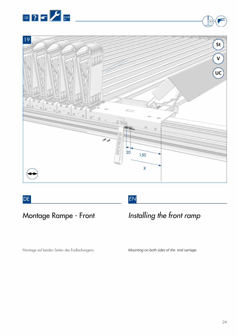
Montage Rampe - Front Installing the front ramp
X
15020
Montage auf beiden Seiten des Endlaufwagens. Mounting on both sides of the end carriage.
4,1
V
UC
St
DE EN
19
?
25
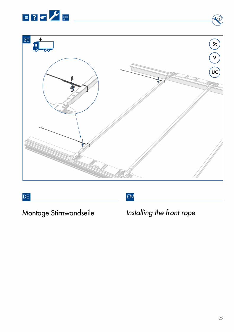
Montage Stirnwandseile Installing the front rope
8
V
UC
St
DE EN
20

?
26
Überprüfung der Seilspannung mittels Zugstange
Checking the cable tension using a tension rod
V
UC
St
DE EN
21
!≥ 40 mm

?
27
Dichtungen einschieben Inserting the sealing
DE EN
22
V
UC
St

?
28
Dachaussteifung 4-Seil 4-cable roof reinforcement
!
DE EN
23
V
UC
St

?
29
Montage Seiladapter - Front Installing the rope adapter - Front
~ 480
650/692
66
6,9
17
8
Siehe Seite 38 See page 38
DE EN
24
V
UC
St

?
30
Seilanbindung- Seiladapter - Front
Cable connection- Rope adapter - Front
DE EN
25
V
UC
St

?
31
Seilanbindung- Montagesatz - Front
Cable connection- Installation set - Front
DE EN
26
V
UC
St

?
32
Seilanbindung- Portalbalken - Heck
Cable connection- Gantry beam - Rear
135
15 Nm
DE EN
27
V
UC
St

?
33
135
Montage Seiladapter - Mitte Installing the rope adapter - Centre
DE EN
28
V
UC
St

?
34
Seilanbindung- Seiladapter - Mitte
Cable connection- Rope adapter - Centre
1
1
2
2
DE EN
29
V
UC
St

?
35
!
13
V
UC
St
+/_
+/_
≥ 16 mm
!
1) Montage Seilstraffer mittels Kabelbindern
2) Einstellung der Seilspan-nung, 4-Seil-Dachaussteifung
1) Installing the cable tensioner using cable ties
2) Setting cable tension, 4-cable roof reinforcement
Min. Einschraubtiefe beachten. Please observe the min. screw depth.
DE EN
30

?
36
Überprüfung der Seilspannung mittels Zugstange
Checking the cable tension using a tension rod
DE EN
31
!
75 kg
100 -125 mm
V
UC
St

?
37
a Fahrtrichtung a Driving direction
Montage Expanderseile Installing the expander cables
ca
V
UC
St
DE EN
32

?
38
Dachplanenbefestigungspunkte Roof plan attachment points
>750 N_
30
30650/ 692
650/ 692 650/
692 650/ 692 650/
692
650/ 692 650/
692 650/ 692
650/ 692
430430
430430
860
860
!
37 37
460,5
Dach 18 / 692 mmDach 19 / 650 mm(Faltplattenabhängig)
Roof 18 / 692 mmRoof 19 / 650 mm(depending on hinge)
470,5
DE EN
33

?
39
Dachplanenbefestigungspunkte DB
Roof plan attachment points DB
650650
650650
650650
650
650
430
430
430
430
430
430
430
430470,5
!
3737
650
460,5
>750 N_
30
30
DBDB-Ausführung: 5 Schnallen / SpriegelDB-design : 5 Buckles / bow
DE EN
34
?
40
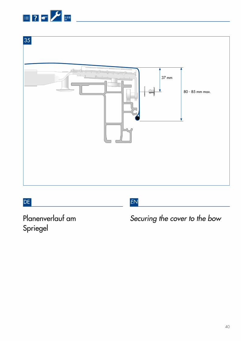
Planenverlauf am Spriegel
37 mm
80 - 85 mm max.
Securing the cover to the bow
DE EN
35

?
41
713
15
20
5
Montage TIR - Heck Installing TIR - Rear
106,5
TIR
DE EN
36V

?
42
Montage TIR - Maxlockam Endlaufwagen / Spriegel
Installing TIR - Maxlockat the end carriage / bow
TIR Maxlock-Zollverschluss an Endlaufwagen und Spriegeln vernieten*
* Spezialwerkzeug erforderlich
Rivet the TIR Maxlock customs security at end carriages and bows*
* Specialist tools are required
*
TIR
DE EN
37V

?
43
8
Montage TIR - Front 01 Installing TIR - Front 01
* Bohrungskanten allseitig abrunden * Chamfer bevelled bore edges on all sides
1.
TIR
*
DE EN
38V

?
44
8
TIR38
V
Montage TIR - Front 02 Installing TIR - Front 02
Weitere Details zur Ausführung auf Anfrage Additional information on implementation available upon request
2.
3.
DE EN
39

?
45
Vorgaben zur Konfektionierung der Seitenplane
Requirements for configuring the side curtain
Standard Aufbau (Code L): Standard structure (code L):
• Mindestanforderungen des Planenmaterials und Kennzeichnung
entsprechend EN 12461-1
• Durchlaufender Quergurt oben
• Anzahl (X) der Seitenplanenroller nach Formel: (L= Aufbaulänge in mm) nach EN 12641-2)
• Minimum requirements for the curtain material and labelling
in accordance with EN 12461-1
• Traversing cross-strap above
• Number (X) of side curtain rollers in accordance with the formula:
(L= length of structure in mm) in accordance with EN 12641-2)
Verstärkter Aufbau (Code XL): Reinforced structure (code XL):
• Mindestanforderungen des Planenmaterials, Kennzeichnung, Anzahl der Seitenplanenroller, Anordnung der Gurte und Prüfung entsprechend EN 12641-2
• Statische Prüfung oder dynamischer Fahrversuch nach EN 12642
• Minimum requirements for the curtain material, labelling, number of side curtain rollers, arrangement of straps, and testing
in accordance with EN 12641-2
• Static testing and dynamic driving testing in accordance with EN 12642
X =L - 550 mm
550 mmX =
L - 550 mm
550 mm
VSt
!
X
DE EN
40

?
46
Variante / Option
Variante / Option
Variante / Option
Variante / Option
Keder Camping1.
A
2.
B
Seitenplanenroller mit TIR-Sicherungs-element (Abreißmutter).Side curtain roller with TIR- safety element (shear nut).
Einen Streifen „KEDER CAMPING“ auf jedem Gurt über der Seitenplanenroller-aufnahme anbringen.
Der Streifen muß so lang sein, das die Auflagefläche der Gurte am ALU-Profil komplett abgedeckt ist.
Attach a „KEDER CAMPING“ strip along the side curtain across each strap of the side curtain roller.
The strip must be sufficiently wide to ensure that the supporting surface of the straps on the aluminium profile is completely covered.
Vorgaben zur Befestigung der Seitenplane
Requirements for attaching the side curtain
Gurt verschweißt und vernäht.Naht so nah wie möglich an denSeitenplanenroller positionieren
Strap welded and sewn.Position the seam as closely as possible to the side curtain roller
Gurt verschweißt und vernietet.Niet so nah wie möglich an den Seitenplanen-roller positionieren
Strap welded and riveted.Position the rivet as closely as possible to the side curtain roller
• Der Seitenplanenroller muss von der Gurtschlaufe eng umschlossen werden
• Kann eine Beschädigung der angrenzenden Bauteile (z. B. Aluprofil) durch den Niet nicht ausgeschlossen werden, muss Variante 1 angewendet werden
• Nietrichtung beachten
• Innen und Außen möglichst geringer Überstand des Niet- kopfes
• The side curtain roller must be tightly enclosed by the strap loops.
• If damage to the adjacent components (e.g. aluminum pro- file) by the rivet cannot be prevented, version 1 must be used
• Ensure correct rivet direction
• Ensure the rivet head protrudes as little as possible on the inside and outside
1. 1.
2. 2.
TIR
Achtung: Bei Verwendung des Volumengurtes muss zusätzlich KEDER CAMPING eingesetzt werden Attention! When using the volu-me strap, KEDER CAMPING needs to be used in addition
Schutzclip Safety clip
DE EN
41

?
47
Dachplanenbefestigung an der Stirnwand
Securing the roof cover to the rear wall
1.
1. 1.
2.
2. 2.
3. 4.
3.
4.
3.
4.1. 1.1.
1.
1.
1.
1. 1.
1.
1. 4.
2.
2.
2.
2.
2.
2.
1.
1.
1.
1. 5.
3.
3.
3.
3.
3.
3.
3.
1.
1.
1.
Seilzug Rope pullPlane
Plane
Tarpaulin
Tarpaulin
Blindniet Blind rived
Blindniet Blind rived
Dachplane Roof tarpaulin
Blindniet
Blindniet
Blind rived
Blind rived
Bügelkrampe
Planenöse
Staple
Tarpaulin eye
Befestigungsleiste Fixing washer
Stirnwand Front bulkhead
Stirnwand
Stirnwand
Front bulkhead
Front bulkhead
Seilzug
StirnwandDachplane
Rope pull
Front bulkheadRoof tarpaulin
Beispiele/ Examples
1.
1. 1.
4.
4. 4.
2.
2. 2.
5.
6.
5.
6.
5.
3.
3. 3.
1.
1.
4.4.
2.
2.2.
2. 6.
5.
5.
3.
3.
3.
2.
3.
Empfohlene Ausführung für beidseitig verschiebbaren Verdeckaufbau Recommended version for top assembly movable on both sides
Sesam KlemmprofilSesam clamping profile
Sesam KlemmprofilSesam clamping profile
1.1.
3.
DE EN
42

?
48
Planenbefestigung am Portalbalken
Securing the cover to the gantry beam
Beispiele/ Examples
1.
1.
2.
2.
3.
1.
1.
1.
1.
2.
3.
4.
2.
2.
2.
5.
3.
3.
3.
Roof tarpaulin
Tarpaulin
Tarpaulin
Blind rived
Welting
Blind rived
Blind rived
Fixing washer
Gantry beam
Gantry beam
Gantry beam
1.
1.
4.
2.
2.
5.
3.
3.
Sesam KlemmprofilSesam clamping profile
Sesam KlemmprofilSesam clamping profile
1.
2.
3.
Dachplane
Plane
Plane
Blindniet
Keder
Blindniet
Blindniet
Befestigungsleiste
Portalbalken
Portalbalken
Portalbalken
1.
1.
1.
1.
1.
1.
4.
2.
5.
3.
1.
1.
1.
1.
1.
1.
1.
1.
2.
2.
3.
3.
DE EN
43

?
49
European Trailer Systems GmbH
113106
26/14
23452014
Ihre Bestellung richten Sie bitte an den für Sie zuständigen Partner oder Fahrzeugbauer. Anm.: Informationen finden Sie auch auf der Internetseite im PDF unseres aktuellen Ersatzteilkataloges
Send your order to the partner responsible for you or to the vehicle manufacturer. Note: Information may also be found on our website in the form of a PDF-document of our current spare parts catalogue
(www.EdschaTS.com)Ersatzteile
Spare Parts
CURTAIN-SIDER-VERDECK · CURTAIN-SIDER ROOF
DE|EN 2015 |08

European Trailer Systems GmbHIm Moerser Feld 1f, 47441 Moers, GermanyPhone: +49 (0) 2841 6070 700 · Fax: +49 (0) 2841 6070 333 www.EdschaTS.com
Alle
tech
nisc
hen
Änd
erun
gen
vorb
ehal
ten
· Sub
ject
to te
chni
cal c
hang
es ·
09/
2016
No.
38
08
3 6
80


