Differential Pressure Meter Media 6 with LCD Media 6 with LED Mounting and Operating Instructions EB 9527-1 EN Firmware A 2.11 (LCD), B 2.11 (LED) Edition July 2004 Fig. 1 ⋅ Media 6 with LCD and attached valve block, Media 6 with LED (right) LED
Transcript
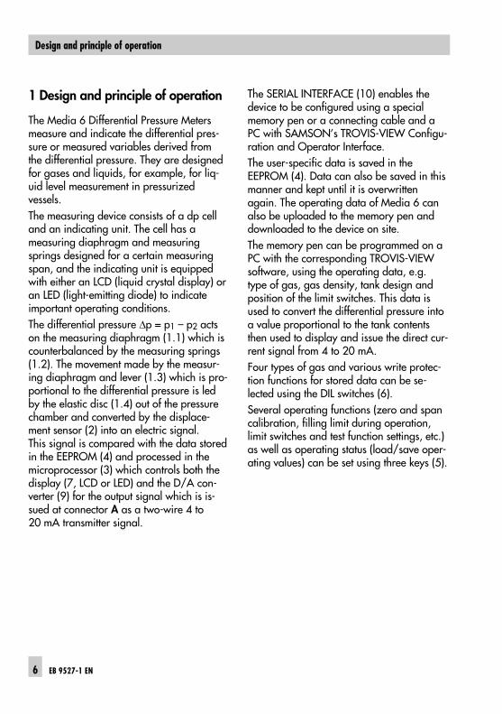
Differential Pressure MeterMedia 6 with LCDMedia 6 with LED
Mounting andOperating Instructions
EB 9527-1 ENFirmware A 2.11 (LCD), B 2.11 (LED)Edition July 2004
Fig. 1 ⋅ Media 6 with LCD and attached valve block, Media 6 with LED (right)
Assembly, commissioning and operation of the device may only be per-formed by trained and experienced personnel familiar with this product.According to these mounting and operating instructions, trained personnelis referred to persons who are able to judge the work they are assigned toand recognize possible dangers due to their specialized training, theirknowledge and experience as well as their knowledge of the relevantstandards.
Explosion-protected versions of this device may only be operated by per-sonnel who have undergone special training or instructions or who areauthorized to work on explosion-protected devices in hazardous areas.See section 9 for more details.
Any hazards which could be caused by the process medium and the oper-ating pressure in the instrument are to be prevented by means of appropri-ate measures.Make sure that the instrument is only used where temperatures and operat-ing pressure do not exceed the sizing data specified in the order. The Media 6 Differential Pressure Meter is not certified for measuringflammable gases or liquids in Zone 0 areas.
Proper shipping and appropriate storage are assumed.
Note! Devices with the CE mark meet the requirements specified in theDirective 94/9/EC and the Directive 89/336/EEC.The Declaration of Conformity can be viewed and downloaded on the In-ternet at http://www.samson.de.
EB 9527-1 EN 3
Modifications in device firmware compared to the previous version
Previous version New version
A 2.03 / B 2.03 A 2.10 / B 2.10
Limit switches The limit switches A1 and A2 are configured over software asminimum and maximum alarms. They can be adjusted separately over the keys on the device.
Filling limit during oper-ation
The filling limit during operation UCW can be set over the keyson the device independently of the limit switches
A 2.10 / B 2.10 A 2.11 / B 2.11
Error code The current output of the Media 6 device is switched to≥ 3.6 mA
4 EB 9527-1 EN
Previous version New version
EB 9527-1 EN 5
1 Design and principle of operation
The Media 6 Differential Pressure Metersmeasure and indicate the differential pres-sure or measured variables derived fromthe differential pressure. They are designedfor gases and liquids, for example, for liq-uid level measurement in pressurizedvessels.The measuring device consists of a dp celland an indicating unit. The cell has ameasuring diaphragm and measuringsprings designed for a certain measuringspan, and the indicating unit is equippedwith either an LCD (liquid crystal display) oran LED (light-emitting diode) to indicateimportant operating conditions.The differential pressure ∆p = p1 – p2 actson the measuring diaphragm (1.1) which iscounterbalanced by the measuring springs(1.2). The movement made by the measur-ing diaphragm and lever (1.3) which is pro-portional to the differential pressure is ledby the elastic disc (1.4) out of the pressurechamber and converted by the displace-ment sensor (2) into an electric signal. This signal is compared with the data storedin the EEPROM (4) and processed in themicroprocessor (3) which controls both thedisplay (7, LCD or LED) and the D/A con-verter (9) for the output signal which is is-sued at connector A as a two-wire 4 to20 mA transmitter signal.
The SERIAL INTERFACE (10) enables thedevice to be configured using a specialmemory pen or a connecting cable and aPC with SAMSON’s TROVIS-VIEW Configu-ration and Operator Interface. The user-specific data is saved in the EEPROM (4). Data can also be saved in thismanner and kept until it is overwrittenagain. The operating data of Media 6 canalso be uploaded to the memory pen anddownloaded to the device on site.The memory pen can be programmed on aPC with the corresponding TROVIS-VIEWsoftware, using the operating data, e.g.type of gas, gas density, tank design andposition of the limit switches. This data isused to convert the differential pressure intoa value proportional to the tank contentsthen used to display and issue the direct cur-rent signal from 4 to 20 mA.Four types of gas and various write protec-tion functions for stored data can be se-lected using the DIL switches (6).Several operating functions (zero and spancalibration, filling limit during operation,limit switches and test function settings, etc.)as well as operating status (load/save oper-ating values) can be set using three keys (5).
6 EB 9527-1 EN
Design and principle of operation
Fig. 2 ⋅ Functional diagram
0
20
40 60
80
100% m3
#
7
6
5
3
2
1.1
1.2
9
8
10
1.5
4
1.4
1.3
1.2
1
p2 p1_ +
Connector AUB = 12 to 36 V DCIA = 4 to 20 mA
Min./max. alarm A1
Connector B
Min./max. alarm A2
µPEEPROM
SERIAL INTERFACE
Indicating unit with LCD or LED
1 Differential pressure cell1.1 Measuring diaphragm1.2 Measuring springs1.3 Lever1.4 Elastic disc1.5 Diaphragm axis2 Displacement sensor3 Microprocessor4 Memory5 Keys 6 DIL switches7 Indicating unit with
LCD or LED8 Limit switch9 D/A converter10 SERIAL INTERFACE
Valve blockwith pressuregauge
Differentialpressure cell
EB 9527-1 EN 7
Design and principle of operation
1.2 Technical dataDifferential pressure meter
Nominal range mbar 0to
100
0to
160
0to
250
0to
400
0to
600
0to
1000 1)
0to
1600 1)
0to
25001)
0to
3600 1)
Adjustable span mbar
Class ± 1.0 % fromto
≤ 250≥ 125
≤ 400≥ 100
≤ 600≥ 150
≤ 1000≥ 250
≤ 1600≥ 400
≤ 2500≥ 500
≤ 3600≥ 720
Class ± 1.6 % fromto
≤ 100≥ 60
< 160≥ 60
< 125≥ 50
< 100≥ 80
< 150≥ 120
< 250≥ 200
Class ± 2.5 % fromto
< 60≥ 35
< 60≥ 32
fromto
< 35 2)
≥ 20
Nominal pressure PN 40, overloadable on one side up to 40 bar (PN 50 also for oxygen on request)
Display LCD Ø 90 or LED Ø 3
Performance Output and indication linear to tank capacity
Deviation from terminal-ba-sed linearity
< ±1.6 % or < ±2.5 % (including hysteresis depending on the span selected)
Sensitivity < 0.25 % or < 0.5 % depending on the span selected
Effect of static pressure ambient temperature
< 0.03 % / 1 barat –20 to 70 °C on zero and span: < ±0.25 %/10 K
Limit switches 2 software limit switches A1 and A2, configurable as minimum or maximum alarmsin accordance with NAMUR and EN 60947-5-6
Control circuit,adjustable in 1% steps
Rating according to connected switching amplifieracc. to NAMUR and EN 60947-5-6, e.g. KFA6- SR2- Ex2.W or KFA-SR2- Ex1.W
Hysteresis 1 % based on maximum tank capacity (MCN)
Range of inversion, approx. < 0.6 %
Weight without valve block with valve block
Approx. 3 kgApprox. 5 kg
1) A class accuracy of 0.6 % can be expected for measuring ranges 1000, 1600, 2500 and 3600 mbar with spans≤ 100 % to ≥ 50 % of the nominal range.
2) The class accuracy of Class 2.5 may not be reached in cases where the span does not fall within this specified span.
Note: All pressures stated as gauge pressures. All errors and deviations stated in % of the adjusted span.
8 EB 9527-1 EN
Technical data
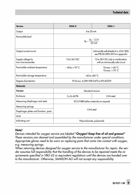
Version 5006-0 5006-1
Output 4 to 20 mA
Permissible load
RB = US – 12 V
20 mA
Output current circuit Intrinsically safe (Media 6 w. LCD/ LED)see PTB 00 ATEX 2074 in appendix
Supply voltage UB two-wire transmitter
12 to 36 V DC 12 to 28 V DC only in combination with an intrinsically safe circuit
Permissible ambient temperature – 40 to + 70 °C T6 max. + 60 °CT5 max. + 70 °C
Permissible storage temperature –40 to +80 °C
Degree of protection IP 65 acc. to DIN VDE 0470 or EN 60529
Materials
Version Standard version
Enclosure Cu Zn 40 Pb CrNi steel
Measuring diaphragm and seals ECO/NBR (other materials on request)
Measuring springsCrNi steel
Diaphragm plates and function. parts
Lever
Indicating unit Polycarbonate, polyamide
Note!Devices intended for oxygen service are labeled "Oxygen! Keep free of oil and grease!"These versions are cleaned and assembled by the manufacturer under special conditions.Appropriate gloves need to be worn on replacing parts that come into contact with oxygen,e.g. measuring springs.When returning devices designed for oxygen service to the manufacturer for repair, the sen-der assumes full responsibility that the handling of the devices to be repaired meets the re-quirements specified in VBG 62 or equivalent regulations until the devices are handed overto the manufacturer. Otherwise, SAMSON AG will not accept any responsibility.
EB 9527-1 EN 9
Technical data
2 Installation
2.1 Arrangement of instruments
2.2 Media 6 Indicating Unit
Make sure that the high-pressure line isconnected to the high-pressure connec-tion and the low-pressure line to the low-pressure connection.
Note! Special fittings are required to connectmeasuring lines. In addition, depending onthe arrangement, connections left unusedmust be fitted with plugs or venting screws (see section 2.5 on accessories for more de-tails).
Clean the connections carefully prior toconnecting the measuring lines. Do notclean the instrument using compressedair or pressurized water.
Secure the instrument at the place of in-stallation to a pipe, wall or mountingplate free of vibration.
For attachment to vertical or horizontalpipes, use a mounting component withclamp. For wall mounting, use a mount-ing part without clamp. See the dimen-sional drawing on page 29 for mountingto control panels.
Note!We recommend installing one shut-off valvein each measuring line and, additionally,an equalizing valve, or a SAMSON valveblock as a compact assembly. Both measuring lines can then be shut off.Additionally, the zero point can be checkedat the indicating unit by bypassing thecircuit.
2.3 Valve block
The three valves combined in a valve blockwith test and pressure gauge connections(Fig. 4), which are flanged directly onto thebottom of the dp cell, are available as anaccessory.
2.4 Shut-off and equalizing valves
As an alternative to the SAMSON valveblock, both shut-off valves as well as the by-pass valve/equalizing valve can also be in-stalled as shown in Fig. 5.
hH
+–
Fig. 3 ⋅ Arrangement for liquid level measurement,e.g. diagram for the standard arrangementin cryogenic applications
10 EB 9527-1 EN
Installation
2.5 Accessories for connections
Open product connections are protectedagainst contamination by means of NBRplugs.Required screw fittings, plugs, ventingscrews and screw joints with restrictionsused to dampen vibrations caused by theprocess medium (especially when measur-ing gases) must be ordered separately.
The screw fittings and SAMSON valveblocks are listed together with their ordernumbers in the Data Sheet T 9555 EN.
Shut-off valve (-)
Fig. 4 ⋅ SAMSON valve block
– +
Test connection Equalizing valve(lead-sealable)
Shut-off valve (+)
Connection formeasuring lines
Pressure gaugeconnection
Bore hole forsealing wire
Media 61 Shut-off valve2 Equalizing valve
Fig. 5 ⋅ Shut-off and equalizing valves, separate orcombined in a three-way or five-way valve block
1
2
From the point of measurement
To indicating unit
EB 9527-1 EN 11
Installation
3 Electrical connection
As far as the electrical installation ofthe device is concerned, the relevantnational regulations governing theinstallation of electrical equipmentand the national accident preventionregulations of the country of destina-tion must be adhered to. In Ger-many, these are the VDE regulationsand accident prevention regulationsof the employer’s liability insurance.For assembly and installation in haz-ardous areas, the following stand-ards apply: EN 60079-14: 1997;VDE 0165 Part 1/8.98 "Electricalapparatus for explosive gas areas"and EN 50281-1-2: VDE 0165 Part2/11.99 "Electrical apparatus for usein the presence of combustible dust." For intrinsically safe electrical ap-paratus that are certified accordingto the Directive 79/196/EEC, thedata specified in the certificate ofconformity apply for connection ofintrinsically safe circuits.For intrinsically safe electrical ap-paratus that are certified accordingto the Directive 94/9/EC, the dataspecified in the EC type examinationcertificate apply for connection of in-trinsically safe circuits.Note: It is absolutely necessary tokeep to the terminal plan specifiedin the certificate. Reversal of the elec-trical connections may cause the ex-plosion protection to be ineffective!Do not tamper with screws inside oron the case which have been sealedwith paint.
Note on the selection of cables and wires:To run several intrinsically safe circuits in amulti-core cable, read paragraph 12 of EN60079-14; VDE 0165/8.98.For generally used insulating materials, forexample polyethylene, the radial thicknessof the conductor insulation has to be at least0.2 mm.The diameter of a single wire in a flexibleconductor shall not be smaller than 0.1 mm.The conductor ends are to be protectedfrom unlaying, e.g. by using wire end fer-rules.
12 EB 9527-1 EN
Electrical connection
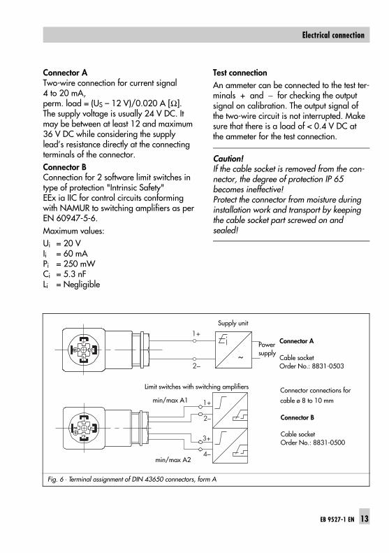
Connector ATwo-wire connection for current signal4 to 20 mA, perm. load = (US – 12 V)/0.020 A [Ω].The supply voltage is usually 24 V DC. Itmay be between at least 12 and maximum36 V DC while considering the supplylead’s resistance directly at the connectingterminals of the connector.Connector B Connection for 2 software limit switches intype of protection "Intrinsic Safety"EEx ia IIC for control circuits conformingwith NAMUR to switching amplifiers as perEN 60947-5-6.Maximum values:Ui = 20 VIi = 60 mAPi = 250 mWCi = 5.3 nFLi = Negligible
Test connectionAn ammeter can be connected to the test ter-minals + and − for checking the outputsignal on calibration. The output signal ofthe two-wire circuit is not interrupted. Makesure that there is a load of < 0.4 V DC atthe ammeter for the test connection.
Caution! If the cable socket is removed from the con-nector, the degree of protection IP 65becomes ineffective! Protect the connector from moisture duringinstallation work and transport by keepingthe cable socket part screwed on andsealed!
Fig. 6 ⋅ Terminal assignment of DIN 43650 connectors, form A
~
1+
2–
1
3
2
Supply unit
Connector A
Cable socketOrder No.: 8831-0503
Connector connections forcable ø 8 to 10 mm
Powersupply
1
3
2
4
1+
2–
3+
4–
min/max A1
min/max A2
Limit switches with switching amplifiers
Connector B
Cable socketOrder No.: 8831-0500
EB 9527-1 EN 13
Electrical connection
4 Operation
0
20
40 60
80
100%m3
x1000
– +
Off
SERIALINTERFACE
SWITCHES1·2 GAS SELECTION
3 ON·SPAN4 ON·WRITE
TEST
ONOFF
1 234
PROTECTION
DIL switches Up key Down key Enter key Test connection
Alarm A2flashingUCWflashing
Tank capacityMCN, SCN,UCW,diff. pressure anderror code
Unit of quantity,tank capacityand ∆ p
Nom. perm. capacity SCN
Tank capacity % Gas type and operating status Factor Tank designation
Light-emitting diode
Plug-in plate for gas types and measuring
ranges
Note!A quick guide is located behind theplug-in plate of Media 6 with LED.
Alarm A1flashing
Interface
Openequalizing valve
Tank ID
Fig. 7 ⋅ Indicating unit with LCD (top) and LED (bottom)
Ar XX,X mbar... XXXX,X mbar
Span: Start - Value End - Valvue
XX,X mbar... XXXX,X mbar
XX,X mbar... XXXX,X mbar
XX,X mbar... XXXX,X mbar
O2
N2
CO2
14 EB 9527-1 EN
Operation
4.1 Display and operating elements
All the necessary information and measuredvalues stored in the instrument’s memoryare shown in the display of Media 6 withLCD. Although the Media 6 with LED ver-sion does not have such a digital display,important operating conditions are indi-cated by the LED.
Three keys are used to operate the differen-tial pressure meter:
Up keyDown keyEnter key
and a DIL switch with four switches to selectthe type of gas and write protection function.
4.1.1 Changing over display modefor Media 6 with LCD
Press the key to change over from thestandard display to seven other displaymodes.After 8 seconds or after the message has fin-ished running across the display, the dis-play returns automatically to the standarddisplay. O2 e.g. gas name and current tank
content∆P current differential pressureMCN maximum capacity nominalMCN/R 100 % capacity assigned to
20 mA signalSCN save capacity nominal
geometric capacity up to overflow/gauge pipe
SCN/R 100 % capacity assigned to 20 mA signal
UCW useable capacity work ∆P100 maximum differential pressurePTANK nominal tank pressure
Indicated value corresponds to the pressure assigned to the density(liquid)as per vapor pressure diagram. If the calculations for MCN and SCN are based on density(liquid) at 1 bar abs, then 1 bar is shown for PTANK.
X-TANK-16 e.g. tank ID as running textERROR error message displayed auto-
matically when an error occurs(see section 8 on troubleshooting).
OFF Special signal on opening theequalizing valve, I = 3.6 mA(refer to EB 9527-2, page 7).
EB 9527-1 EN 15
Operation
5 Start-up
1. Open the equalizing valve.2. Slowly open the high-pressure line.3. Close the equalizing valve or the by-
pass of the valve block.4. Open the low-pressure line.
Note!Carry out, if necessary, a zero point checkat the dp cell as described in section 6.3,and restart the instrument.
6 Setting
6.1 Write protection
The instrument has two write protection func-tions:WRITE PROTECTION to prevent the operating data from beingchanged unintentionally.SPAN PROTECTION as an additional write protection for thespan setting.The write protection at switch 4 of the DILswitch must first be switched OFF beforevarious operating functions can be carriedout and switched ON again afterwards.
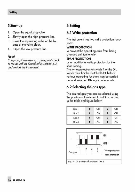
6.2 Selecting the gas type
The desired gas type can be selected usingthe positions of switches 1 and 2 accordingto the table and figure below.
Gas 1 1 OFF 2 OFF
Gas 2 1 ON 2 OFF
Gas 3 1 OFF 2 ON
Gas 4 1 ON 2 ON
Fig. 8 ⋅ DIL switch with switches 1 to 4
ON
OFF
1 2 3 4Gas type
Span protection
Write protection
16 EB 9527-1 EN
Setting
Media 6 with LCDThe gas formula of the gas chosen, e.g. AR, CO2, O2, N2, etc. appears in thedisplay.
Select the gas type according to thetable using the DIL switch.
The display is not activated, just the selectedgas is shown!
Press key to confirm the new gas type. The display is activated.
Media 6 with LEDThe four selectable gas types are listeddownward from 1 to 4 or specified bymeans of their designation on the plug-inplate. Use the switches 1 and 2 of the DILswitch to select the gas type, also refer tothe table and Fig. 8 on page 16. The gastype selected is indicated by the number ofshort flashes.Gas 1: pause - 1 flash - pause etc.Gas 2: pause - 2 flashes - pause etc.Gas 3: pause - 3 flashes - pause etc.Gas 4: pause - 4 flashes - pause etc.
Press key to confirm the new gas type. The LED goes out.
6.3 Checking zero
When the zero is checked, the pressuremust be equal in both measuring chambersat atmospheric pressure. At a differential pressure of ∆p = 0 mbar,the current signal at connector A or at theTEST connection must be 4 mA.(See test arrangement in Fig. 9.)
Note! When activating the gas column correction(refer to section 2.2.3 in EB 9527-2 EN), itis important to take into account that thegas columns in the measuring lines reducethe differential pressure as they have an op-posing effect on each other.At a pressure equilibrium of ∆p = 0 mbar,the meter readout is negative for the tankcapacity and the output signal indicates avalue < 4 mA.In this case, readjust the zero point as de-scribed in following so that the display indi-cates 0 % = 0000 when ∆p = 0 mbar. Theoutput signal changes, but indicates a value< 4 mA in accordance with the gas columncorrection data.
Media 6 with LCDAt a differential pressure of ∆p = 0 mbar,the display must indicate 0 % or 0000.Correction when the tank is empty
Write protection: turn switch 4 OFF.Press and hold down key. ZERO andX,0X mbar appear in the display.Current signal I shows the present mA value.Press key, zero point is adjusted.
EB 9527-1 EN 17
Setting
Release key, 0 mbar appears in thedisplay. Current signal I = 4 mA.
Activate the write protection: turn switch4 ON.
Correction when the tank is filledIf the differential pressure lines areequipped with shut-off and equalizingvalves, zero can be checked even when theplant is in operation. To achieve this, place the valve block orequalizing valve in the test position to ob-tain the same pressure in both measuringchambers.1. Close the shut-off valve in the high-
pressure line. 2. Open the equalizing valve or bypass in
the valve block. 3. Close the shut-off valve in the low-
pressure line.The valve block is in test position!
Write protection: turn switch 4 OFF. Press and hold down key. ZERO and
X,X mbar appear in the display. Current signal I indicates the present mA value.
Press key. Zero is adjusted. Release key, 0 mbar appears in the
display.Current signal I = 4 mA corresponding tothe liquid level at 0 mbar differential pressure.
(See note on gas column correction on page 17.)
Activate the write protection: turn switch 4 ON.
Return valve block or equalizing valve tooperating position:
1. Open the shut-off valve in the low-pressure line.
2. Close equalizing valve.3. Open the shut-off valve in the high-
pressure line.
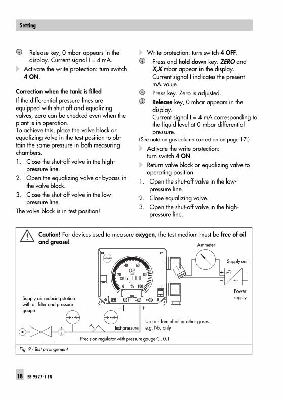
Fig. 9 ⋅ Test arrangement
0
20
40 60
80
100%m3
x1000
– +
Off
.
~
– +
–+
Supply air reducing stationwith oil filter and pressuregauge
Powersupply
Supply unit
Ammeter
Precision regulator with pressure gauge Cl. 0.1
Test pressureUse air free of oil or other gases,e.g. N2, only
Caution! For devices used to measure oxygen, the test medium must be free of oiland grease!
18 EB 9527-1 EN
Setting
Media 6 with LEDAccording to the test arrangement, a cur-rent signal of 4 mA must be supplied at con-nector A or at the TEST connection at a dif-ferential pressure of ∆p = 0 mbar.Correction when the tank is filled1. Close the shut-off valve in the high-
pressure line. 2. Open the equalizing valve or bypass in
the valve block. 3. Close the shut-off valve in the low-
pressure line.The valve block is in test position!
Write protection: turn switch 4 OFF. Press and hold down key. LED starts to
flash rapidly. Current signal I indicatesthe present mA value.
Press key. Zero is adjusted. Current signal I = 4 mA corresponding to the liquid level at 0 mbar differential pressure. For gas column correction, the following applies: I < 4 mA.(See also the note on gas column correctionon page 17.)
The LED flashes continuously for ~ 2 s. Release key.
Return valve block or equalizing valve tooperating position:
1. Open the shut-off valve in the low-pressure line.
2. Close the equalizing valve.3. Open the shut-off valve in the high-
pressure line, the LED goes off.
Activate the write protection: turn switch4 ON.
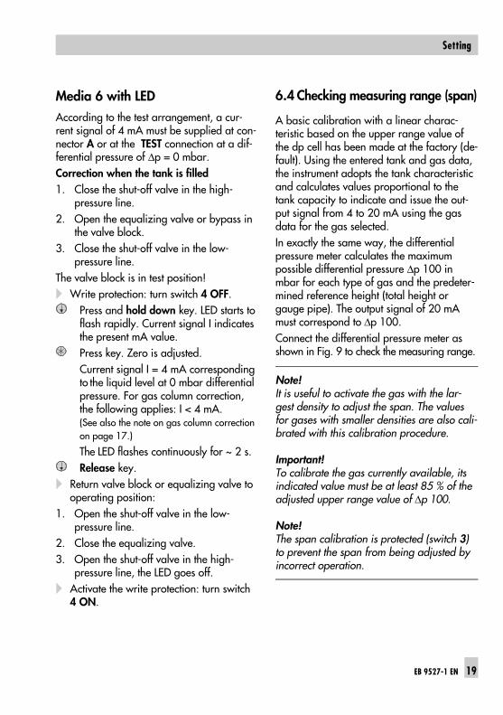
6.4 Checking measuring range (span)
A basic calibration with a linear charac-teristic based on the upper range value ofthe dp cell has been made at the factory (de-fault). Using the entered tank and gas data,the instrument adopts the tank characteristicand calculates values proportional to thetank capacity to indicate and issue the out-put signal from 4 to 20 mA using the gasdata for the gas selected. In exactly the same way, the differentialpressure meter calculates the maximumpossible differential pressure ∆p 100 inmbar for each type of gas and the predeter-mined reference height (total height orgauge pipe). The output signal of 20 mAmust correspond to ∆p 100. Connect the differential pressure meter asshown in Fig. 9 to check the measuring range.
Note!It is useful to activate the gas with the lar-gest density to adjust the span. The valuesfor gases with smaller densities are also cali-brated with this calibration procedure.
Important!To calibrate the gas currently available, itsindicated value must be at least 85 % of theadjusted upper range value of ∆p 100.
Note!The span calibration is protected (switch 3)to prevent the span from being adjusted byincorrect operation.
EB 9527-1 EN 19
Setting
Media 6 with LCD
Checking the measuring range (span)
If the key is pressed five times, ∆p100,which is the value for the maximum differen-tial pressure, appears in the display.
First check zero, as described in section6.3. Press key five times, Readout: ∆p 100 = X.XXX ( x1000 ) mbar.
Use a precision regulator to apply a testpressure corresponding to the maximumdifferential pressure ∆p 100 while moni-toring the pressure gauge.
Set point values: ∆p = 0 mbar = 4 mA(See also note on gas column correction on p. 17)
∆p 100 = XXXX mbar = 20 mAIf the readout and output signal do notcorrespond with the indicated value ∆p100,the upper range value of the measuringrange (span) must be calibrated.
Use a precision regulator to apply a testpressure corresponding to the maximumdifferential pressure ∆p 100 while moni-toring the pressure gauge.Keep key pressed down, the current measured value is shown in the display. Current signal I shows the present mAvalue.
Press key, the span is calibrated,current signal goes to 20 mA. Readout = ∆p 100.
Release key.
Turn write protection (switch 4) and spanprotection (switch 3) ON.
Media 6 with LEDChecking the measuring range (span)
First check zero, as described in section6.3.
Use a precision regulator to apply a testpressure corresponding to the maximumdifferential pressure ∆p 100 while moni-toring the pressure gauge.
Set point values: ∆p = 0 mbar = 4 mA (See also note on gas column correction on p. 17)
∆p 100 % = XXXX mbar = 20 mAIf the output signal I does not correspondwith the value ∆p100 %, the upper rangevalue of the measuring range (span) mustbe calibrated.
Calibrating the measuring range (span)
Turn write protection (switch 4) and spanprotection (switch 3) OFF.
Use a precision regulator to apply a testpressure corresponding to the maximumdifferential pressure ∆p 100 while moni-toring the pressure gauge.Keep key pressed down, current signal Ishows the present mA value.LED starts to flash rapidly.
Press key, the span is calibrated,current signal goes to 20 mA, The LED flashes continuously for ~ 2 s.
Release key, the LED goes out.
20 EB 9527-1 EN
Setting
Turn write protection (switch 4) and spanprotection (switch 3) ON.
6.5 Setting limit switches
6.5.1 Max. limit for filling limit dur-ing operation
Note! The filling limit during operation setover the software can only be changed overthe keys in the Media 6 version with LCD.
UCW Marker
Turn write protection (switch 4) OFF.
Press and hold down key until after 8 sUCW appears at the top of the displayand underneath the associated % value.Press key to confirm the display. Press to reduce the value in steps of 1 %orPress to increase the value.Press key to confirm new setting.
Turn write protection (switch 4) ON.
6.5.2 Alarms A1 and A2
Media 6 with LCD
Alarm A1 and A2 markersBoth limit switches are already set over thesoftware either as min. or max. contacts. A1MIN or A1MAX as well as A2MIN orA2MAX appear in the display. Both limit switches must be set and con-firmed separately.
Turn write protection (switch 4) OFF.
Press and hold down key until after 8 sUCW appears at the top of the display.or needs to be pressed to switch between alarm A1 or A2.Press key to confirm selected alarm. Press to reduce the value in steps of 1 %orPress to increase the value.Press key to confirm new setting.Press and hold down key again untilafter 8 s UCW appears at the top ofthe display.or needs to be pressed to switch overto the second alarm that needs to be set.Confirm selected alarm and set as described above.
Turn write protection (switch 4) ON.
EB 9527-1 EN 21
Setting
Media 6 with LEDConnect an ammeter to the power supply atconnector A (Fig. 9) or to the TEST terminal. Both limit switches are already set over thesoftware as either min. alarm or max.alarm and are displayed to the assigned dif-ferential pressure corresponding to a cur-rent between 4 and 20 mA.Both alarms need to be set and confirmedseparately.
Turn write protection (switch 4) OFF.
Alarm A1
Press and hold down key until after 8seconds the LED flashes slowly.Press key to display the currently setA1 alarm at the ammeter. The LED lights up.Press to reduce the value in steps of 1 %orPress to increase the value.Press key to confirm new setting. TheLED goes off.
Alarm A2
Press and hold down key until after 8seconds the LED flashes slowly.
or needs to be pressed to switch overto A2 alarm which flashes more quickly.Press key to confirm the selected alarm.The LED lights up. The currently set A2 alarm is indicated at the ammeter. Press to reduce the value in steps of 1 %orPress to increase the value.Press key to confirm new setting. TheLED goes off.
Turn write protection (switch 4) ON.
22 EB 9527-1 EN
Setting
6.6 Ammeter function
In order to check the functioning of con-nected devices, an output signal of 4 to 20or 22.8 mA can be adjusted for a shorttime regardless of the current liquid level inthe tank.
Media 6 with LCD
Write protection: turn switch 4 OFF.
4 mA ammeter
Press and hold down key.Press within 8 seconds and hold down, output signal I = 4.0 mA. Release to change the signal between4.0 mA and 22.8 mA.Release key, current signal I indicates the mA value corresponding to the tank capacity.
20 mA ammeter
Press and hold down key.Press within 8 seconds and hold down,output signal I = 20.0 mA.Release to change the signal between20.0 mA and 22.8 mA.Release key, current signal I indicates themA value corresponding to the tank capacity.
Write protection: turn switch 4 ON.
Media 6 with LED
Write protection: turn switch 4 OFF.
4 mA ammeter
Press and hold down key.Press within 8 seconds and hold down, output signal I = 4.0 mA, signaled by rapid flashing of the LED. Press to change the signal between4.0 mA and 22.8 mA (LED on).Release key, current signal I indicates the mA value corresponding to the tank capacity (LED off).
20 mA ammeter
Press and hold down key.Press within 8 seconds and hold down,output signal I = 20.0 mA, signaled by slow flashing of the LED.Press to change the signal between20.0 mA and 22.8 mA (LED on).Release key, current signal I indicates themA value corresponding to the tank capacity. The LED goes out.
Write protection: turn switch 4 ON.
EB 9527-1 EN 23
Setting
7 Memory pen – communication
7.1 Data transfer using memory pen
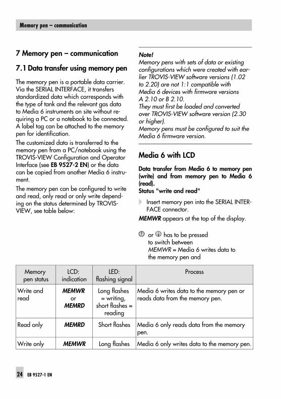
The memory pen is a portable data carrier.Via the SERIAL INTERFACE, it transfersstandardized data which corresponds withthe type of tank and the relevant gas datato Media 6 instruments on site without re-quiring a PC or a notebook to be connected.A label tag can be attached to the memorypen for identification.The customized data is transferred to thememory pen from a PC/notebook using theTROVIS-VIEW Configuration and OperatorInterface (see EB 9527-2 EN) or the datacan be copied from another Media 6 instru-ment.The memory pen can be configured to writeand read, only read or only write depend-ing on the status determined by TROVIS-VIEW, see table below:
Note!Memory pens with sets of data or existingconfigurations which were created with ear-lier TROVIS-VIEW software versions (1.02to 2.20) are not 1:1 compatible withMedia 6 devices with firmware versionsA 2.10 or B 2.10. They must first be loaded and convertedover TROVIS-VIEW software version (2.30or higher).Memory pens must be configured to suit theMedia 6 firmware version.
Media 6 with LCD
Data transfer from Media 6 to memory pen(write) and from memory pen to Media 6(read).Status "write and read"
Insert memory pen into the SERIAL INTER-FACE connector.
MEMWR appears at the top of the display.
or has to be pressed to switch betweenMEMWR = Media 6 writes data tothe memory pen and
Memory pen status
LCD: indication
LED:flashing signal
Process
Write and read
MEMWR or
MEMRD
Long flashes = writing,
short flashes =reading
Media 6 writes data to the memory pen orreads data from the memory pen.
Read only MEMRD Short flashes Media 6 only reads data from the memorypen.
Write only MEMWR Long flashes Media 6 only writes data to the memory pen.
24 EB 9527-1 EN
Memory pen – communication
MEMRD = Media 6 reads data from thememory pen.
MEMRD write protection: turn switch 4OFF.
Press key to activate selection.RUN appears in the display,when DONE appears, the data is saved and the memory pen can be removed.
MEMRD write protection: turn switch 4 ON.
Data transfer from memory pen to Media 6Status "read only"
Write protection: turn switch 4 OFF.
Insert memory pen into the SERIAL INTER-FACE connector.
MEMRD appears at the top of the display.Press key to start the reading process.RUN appears in the display,when DONE appears, the data is saved in Media 6, the memory pen can be removed.
Write protection: turn switch 4 ON.
Data transfer from Media 6 to memory penStatus "write only"
Insert memory pen into SERIAL INTER-FACE connector.
MEMWR appears at the top of the display.Press key to start the writing process.RUN appears in the display,when DONE appears, the data is savedin the memory pen, the memory pencan be removed.
Media 6 with LED
Data transfer from Media 6 to memory pen(write) and from memory pen to Media 6(read).Status "write and read"
Insert memory pen into the SERIAL INTER-FACE connector.
Short flashing of the LED indicates thatMedia 6 reads data from the memory penand long flashing means that Media 6writes data to the memory pen.
or has to be pressed to switchbetween the functions Media 6 writesdata to memory pen and Media 6 readsdata from memory pen.
When selecting the function Media 6 reads data from memory pen:turn switch 4 OFF.
Press key to activate selection, the LED is on.
When the LED goes off, remove the memory pen.
Write protection: turn switch 4 ON.
Data transfer from memory pen to Media 6Status "read only"
Write protection: turn switch 4 OFF.
Insert memory pen into SERIAL INTER-FACE connector.
The LED signals short flashes.Press key to start the reading process,the LED is on.
When the LED is off, remove the memory pen.
Write protection: turn switch 4 ON.
EB 9527-1 EN 25
Memory pen – communication
Data transfer from Media 6 to memory penStatus "write only"
Insert the memory pen into the SERIALINTERFACE connector.
The LED signals long flashes.Press key to start the writing process, the LED is on.
When the LED goes out, remove the memory pen.
7.2 Communication with PC
Media 6 can also be operated via theSERIAL INTERFACE from a PC/notebookusing the TROVIS-VIEW Configuration andOperator Interface.Refer to the Mounting and Operating Instructions EB 9527-2 EN for operation.
8 Troubleshooting
Errors that occur are reported in the upperpart of the LC display with the word ERRORand below with an error code, e.g. 16. The type of flashing sequence signals theerror code of Media 6 with LED. Thus, errorcode 1 is signaled as follows:
long medium 9x short
Refer to the table on page 27 for the de-scription of the error codes.Reset or acknowledge errors by pressingthe key. Any new error messages then remain sup-pressed for 8 seconds. Troubleshooting using the memory penIf you have a SAMSON memory pen, it canbe used, if necessary, to upload new datato the instrument within the 8 seconds.Troubleshooting using a PC or notebookCommunication with a PC or notebook viathe SERIAL INTERFACE functions even in theerror mode.Hardware errorsThese errors are saved in the EEPROM andreset via the SERIAL INTERFACE after repairat the manufacturer’s.Calibration and measuring range error orerror in the tank characteristicYou can only exit the error mode by reset-ting.If necessary, new data must first be readinto the device (see section 7.1).
26 EB 9527-1 EN
Troubleshooting
Error code Description Corrective measure
LCD: number LED: flashing sequence
Hardware error
1 1x long/1x medium/9x short
Oscillating circuit or differentialinductor defect
Send device to SAMSON for repair
2 1x long/1x short/1x medium/8x short
RAM checksum error, RAM is defect Send device to SAMSON for repair
4 1x long/2x short/1x medium/7x short
EEPROM checksum error Send device to SAMSON for repair
Calibration error, measuring range error or error in tank characteristic
8 1x long/3x short/1x medium/6x short
∆p not within permissible range.The permissible range is 20 to 110 %of the nominal range of the dp cell.
Reset error and load other tank or gasdata, or use appropriate dp cell.
16 1x long/4x short/1x medium/5x short
Error in the tank characteristic It is imperative that the co-ordinatesfor the tank characteristic increasestrictly monotonically.
32 1x long/5x short/1x medium/4x short
Calibration ∆p sensor.The zero or span calibrationproduces values that exceed thepermissible limits. These values arenot saved in EEPROM.
Check zero and span calibration. Ondoing so, pay attention to the ∆p.If the fault remains, send device toSAMSON for repair.
Other errors
64 1x long/6x short/1x medium/3x short
Error in FP arithmetic. Check tank or gas data.
128 1x long/7x short/1x medium/2x short
Memory pen invalid. The memory pen ID is incorrect orfaulty. The pen cannot be read,however, writing to the pen is possible.
Use memory pen suitable for Media 6.
256 1x long/8x short/1x medium/1x short
Error in checksum memory pen. Acknowledge error and rewrite orreread memory pen. If the errorcontinues to occur, the memory penmust be replaced.
512 1x long/9x short/1x medium
Error during RS 232 communication. The USART has recognized an error,or there is a buffer overflow.
Acknowledge error and checkcommunication.
Note:Error codes might refer to an error addition and therefore two error codes might be displayed as one code:e.g. ERROR 24 => error code 8 and error code 16. When an error code is displayed, the current output of the Media 6 device is switched to ≥ 3.6 mA.
EB 9527-1 EN 27
Troubleshooting
After acknowledging using the key,8 seconds remain until a new error mess-age can appear. The short time interval is long enough tostart the transfer of new data from the mem-ory pen.The instrument is automatically reset on re-moving the memory pen.With communication using a PC or note-book, the instrument is automatically resetafter the data is transferred.
Other errorsThese errors must be acknowledged bypressing the key to allow the instrumentto continue working.
9 Servicing explosion-protectedversions
In the event that a component of the Media6 on which the explosion protection isbased must be serviced, the instrument mustnot be put back into operation again untilan expert has inspected the device accord-ing to explosion protection requirements,has issued a certificate stating this, or giventhe device a mark of conformity.Inspection by an expert does not have to becarried out, if the manufacturer performs aroutine check test on the device prior to tak-ing it into operation again, and the successof the routine check test is documented byattaching a mark of conformity to the de-vice.Explosion-protected components may onlybe replaced by original checked compo-nents from the manufacturer.
28 EB 9527-1 EN
Servicing explosion-protected versions
10 Dimensions in mm
3054
158
17
30
245.
5
121
114.
5 145.
858
6031
194180.5
32.5148
25.543
80
117 15
8.5
72M8
141.580
37
A
B 0
20
40 60
80
100% m3
Two bore holes ø 8.5 mm for attach-ment to measuring chamber rear sideto fit M8 screws
Two bore holes ø 8.5 mm for attachment to the valve block
Control panel
Pressure gauge acc.to manufacturer
Pressure sensor acc.to manufacturer
Pressure gauge connections:For pressure gauge NG 100: male thread G1/2 B-LH with coupling sleeve G1/2DIN 16 283 and O-ring 12x2For pressure gauge NG 63: female thread G1/4 with seal
EB 9527-1 EN 29
Dimensions in mm
30 EB 9527-1 EN
EB 9527-1 EN 31
32 EB 9527-1 EN
EB 9527-1 EN 33
SAMSON AG ⋅ MESS- UND REGELTECHNIKWeismüllerstraße 3 ⋅ 60314 Frankfurt am Main ⋅ GermanyPhone: +49 69 4009-0 ⋅ Fax: +49 69 4009-1507Internet: http://www.samson.de S/