3714 Kinnear Place Saskatoon, SK Canada S7P 0A6 Ph: (306) 373-5505 Fx: (306) 374-2245 www.littelfuse.com/relayscontrols MPS DEVICENET INTERFACE REVISION 12-C-061015 QUICK SETUP Use the OPI to access the Setup | Hardware | Network Comms menu. Set the Network ID for the device. Set the Baud Rate as DN 125K, DN 250K, or DN 500K. Select the DeviceNet producing assembly (input) from the DeviceNet Produce menu and the DeviceNet consuming assembly (output) from the DeviceNet Consume menu. Select DeviceNet from the Network Type menu. The assembly types can also be set using parameter 472 and 473 via configuration software. Configure the scanner’s polled connections for the selected assembly sizes. The scanner may issue a configuration warning if an I/O size other than the default is used. Disregard the warning. Copyright 2015 Littelfuse Startco All rights reserved. Document Number: PM-1131-EN Printed in Canada
Transcript
3714 Kinnear Place Saskatoon, SK Canada S7P 0A6 Ph: (306) 373-5505 Fx: (306) 374-2245 www.littelfuse.com/relayscontrols
MPS DEVICENET INTERFACE
REVISION 12-C-061015
QUICK SETUP Use the OPI to access the Setup | Hardware | Network Comms menu. Set the
Network ID for the device. Set the Baud Rate as DN 125K, DN 250K, or DN 500K. Select the DeviceNet producing assembly (input) from the DeviceNet Produce menu and the DeviceNet consuming assembly (output) from the DeviceNet Consume menu. Select DeviceNet from the Network Type menu. The assembly types can also be set using parameter 472 and 473 via configuration software.
Configure the scanner’s polled connections for the selected assembly sizes.
The scanner may issue a configuration warning if an I/O size other than the default is used. Disregard the warning.
Copyright 2015 Littelfuse Startco
All rights reserved. Document Number: PM-1131-EN Printed in Canada
Page i MPS DeviceNet Interface Rev. 12-C-061015
This page intentionally left blank.
Page ii MPS DeviceNet Interface Rev. 12-C-061015
TABLE OF CONTENTS SECTION PAGE 1 General ................................................................. 1 2 DeviceNet Interface ............................................. 1 2.1 Network Settings ................................................... 1 2.2 Product Manual Notes ........................................... 1 2.3 Communication Status Display ............................. 2 2.4 DeviceNet LED Indication .................................... 2 2.5 Network Errors ...................................................... 2 2.6 Configuration Using RSNetWorx ......................... 2 3 DeviceNet Objects ............................................... 2 3.1 Identity Object ...................................................... 3 3.2 Message Router ..................................................... 3 3.3 DeviceNet Object .................................................. 4 3.4 DeviceNet Connection Object ............................... 5 3.5 Assembly Object ................................................... 7 3.6 Control Supervisor Object................................... 11 3.7 Overload Class 0x2C .......................................... 16 3.8 Set Point Class 0x64 ........................................... 18 3.9 Acceleration Class 0x65 ...................................... 23 3.10 Digital Input Class 0x66 ..................................... 24 3.11 Analog I/O Class 0x67 ........................................ 26 3.12 RTD Module Class 0x68 ..................................... 27 3.13 RTC Class 0x69 .................................................. 34 3.14 User Register Class 0x6A ................................... 35 3.15 Data Logging Class 0x6B ................................... 36 Appendix A MPS DeviceNet EDS Files ...................... 38 Appendix B MPS DeviceNet Interface Revision History ........................................................................... 39
DISCLAIMER Specifications are subject to change without notice. Littelfuse Startco. is not liable for contingent or consequential damages, or for expenses sustained as a result of incorrect application, incorrect adjustment, or a malfunction.
Page iii MPS DeviceNet Interface Rev. 12-C-061015
This page intentionally left blank.
Page 1 MPS DeviceNet Interface Rev. 12-C-061015
1. GENERAL
This document describes the DeviceNet features supported by the MPS. The MPS supports Explicit and Polled I/O. It does not support the Unconnected Message Manager (UCMM). The MPS requires supply voltage connected to L1 and L2 to power the control unit and 24-Vdc supply voltage to power the isolated DeviceNet transceiver circuit. The DeviceNet transceiver circuit requires 70 mA @ 24-Vdc from the DeviceNet power supply.
2. DEVICENET INTERFACE
2.1 NETWORK SETTINGS DeviceNet settings are located in the Setup Hardware Network Comms menu. Prior to making changes to network settings via the OPI, it is recommended to set the
Network Type to None. Set Network ID to the slave number. Set the Baud Rate to DN 125K, DN 250K or DN 500K. Select the producing assembly instance using the DeviceNet Produce menu and the consuming assembly instance using the DeviceNet Consume menu. See Section 3.5 for assembly details. Once the changes have been made, select DeviceNet from the Network Type menu. 2.2 PRODUCT MANUAL NOTES Appendix E, Register 383: Baud rate selections (Type T17 in Appendix F) includes DeviceNet selections 5:125 kb, 6:250 kb, and 7: 500 kb. Appendix E, Register 385: Network ID range is 0 to 63. Values greater than 63 will be forced to 63.
33
PHASE CURRENT
5 A5 A5 A1 A1 A1 ACBA
--- +++ + 0V
SH
COMM24V
IR IGANIN
PTC
I/O MODULE
62 6061 59 57 5558 56 54 5253
32 31 30 29 28 27 26 25
EARTHLEAKAGE
VOLTAGE
VN
VA
VB
VC
5 A1 A
EFCT
24 23 22 21
20 19 18 17
+V
5 1
VCAN
H
DRAIN
C
N
L
A
Dev iceNet
++
POWER
TRIP
ALARM
ERROR
RESET
MOTOR PROTECTION SYSTEMCONTROL UNIT
MPS-CTU62 61 60 59 58 57 56 55 54 53 52
IRIG
24V
SH
0V
COMM
I/O MODULE
PTCAN IN
OPERATORINTERFACE
35 36 37 39 40
SH
COMMAN
OUT
41 42 43 44 45 46 47 48 49 50 51
24 VDCSOURCE
DIGITAL INPUTSCOM
IN1
IN2
IN3
IN4
IN5
IN6
IN7
HSI
-
234
FIGURE 1. Outline Drawing.
Page 2 MPS DeviceNet Interface Rev. 12-C-061015
2.3 COMMUNICATION STATUS DISPLAY The DeviceNet communication status can be viewed using the Metering Comm State menu. This menu indicates the connection state as ONLINE or OFFLINE. The last communication error is also displayed. The MPS can be programmed to trip if the connection is OFFLINE. The MPS is OFFLINE when there are no connections established and ONLINE when at least one connection is established. 2.4 DEVICENET LED INDICATION
Two LED’s labelled MODULE STATUS (MS) and NETWORK STATUS (NS) are located on the left side of the control unit as shown in Fig. 1. The MS LED is green when the DeviceNet driver is operational. If this LED is off, verify that DeviceNet is selected from the Setup Hardware Network Comms Network Type menu. The NS LED is off when the MPS is the only device on the network. It flashes green when the MPS is physically connected to a network containing other devices but has no established communication connections. It is solid green when a Polling or Explicit Messaging connection is established. It flashes red when one or more connections have timed out. It is solid red if a Duplicate MAC ID or Bus-off error has occurred. Red LED indication requires a restart of the DeviceNet driver. This is done by unplugging and re-connecting the DeviceNet connector, cycling supply voltage or by using the Setup Hardware Network Comms Network Type menu. Select None to shut down the driver and then select DeviceNet to restart. 2.5 NETWORK ERRORS The MPS can be configured to trip or alarm on a network error using the Setup Hardware Network Comms Network Error menu, or by using attribute 0x64 of the DeviceNet object. The Network Error set point sets the action to be taken when the module is off line. Selections are Trip, Alarm, Trip and Alarm, or No Trip or Alarm. Network errors can originate from network watchdog timeouts or the network hardware in the MPS. The last error code is displayed in the Metering Comm State menu. The error codes are listed in the following table.
DEVICENET ERROR CODES ERROR DESCRIPTION
1 Receive Overrun 2 Transmit Overrun 3 CAN Overrun 4 IO Send 5 Duplicate MAC 6 Bus Sense 7 MAC Was Set 8 ID Reset 0 9 ID Reset 1
10 Bus Off 11 CAN ESET 12 CAN ERESET 13 Explicit Timeout 14 IO Timeout 15 IO Delete 16 No CAN Interface
2.6 CONFIGURATION USING RSNETWORX Use the EDS Wizard to register the eds file. The device will register as a Motor Starter named MPS. Select device properties to view Device Parameters. When there is a request to upload from device, select this option. This will load the present configuration from the MPS.
3. DEVICENET OBJECTS (In Order of Class Number)
The module supports the following objects:
CLASS DESCRIPTION 0x01 Identity (1) 0x02 Message Router (1) 0x03 DeviceNet (1) 0x04 Assembly (1) 0x05 Connection (1) 0x29 Control Supervisor (1) 0x2C Overload (1) 0x64 Set Point 0x65 Acceleration 0x66 Digital Input 0x67 Analog I/O 0x68 RTD Module 0x69 RTC Clock 0x6A User Register
(1) Conformance tested using DeviceNet Protocol Conformance Test Software Version A-17.
Page 3 MPS DeviceNet Interface Rev. 12-C-061015
3.1 IDENTITY OBJECT Identity Object Class Services Get_Attribute_Single: Returns contents of specified attribute. Identity Class (1), Instance (0) Attributes
ATTRIBUTE NUMBER
ATTRIBUTE NAME
SERVICES DESCRIPTION DEFAULT, MINIMUM, MAXIMUM
DATA TYPE
1 Revision Get Revision of this object. 1 UINT 2 Max Instance Get Maximum number of instances. 1 UINT
Identity Object Instance Services Get_Attribute_Single: Returns contents of specified attribute. Set_Attribute_Single: Modify the specified attribute. Reset: Performs reset services based on the parameter. No Parameter or Parameter = 0: The DeviceNet driver is reset with the existing MAC ID and baud rate. Parameter = 1: The MAC ID is set to 63 and the baud rate is set to 125 kb. The MPS will then perform a reset that emulates cycling control power. Identity Class (1), Instance (1) Attributes
ATTRIBUTE NUMBER
PARAM ATTRIBUTE
NAME SERVICES DESCRIPTION
DEFAULT, MINIMUM, MAXIMUM
DATA TYPE
COMM REGISTER
1 Vendor ID Get Identification of each vendor by number.
691 UINT
2 Device Type Get Motor Starter 22 UINT 3 Product Code Get Platform Type 201 UINT 0 4 Revision Get Major revision must match
the EDS value. 4.100 A2 02 C6
C6
5 Status Get Summary Status of the Device
0, 0, 255 WORD
6 Serial Number Get Serial Number N/A, 0, 999999999
UDINT 2
7 Product Name Get Human Readable Identification
“Startco MPS” SHORT_ STRING
100 (0x64) 467 Revision Get Revision of Firmware 100 = 1.00
N/A, 100, N/A UINT 1
101 (0x65) 468 System Name Get/Set 22 characters. Only 20 significant.
“Startco MPS” SHORT_ STRING
600
102 (0x66) 469 Password Get/Set 22 characters. Only 4 significant.
“1111” SHORT_ STRING
590
3.2 MESSAGE ROUTER No attributes supported for this object.
Page 4 MPS DeviceNet Interface Rev. 12-C-061015
3.3 DEVICENET OBJECT DeviceNet Object Class Services Get_Attribute_Single: Returns contents of specified attribute.
DeviceNet Class (3), Instance (0) Attributes
ATTRIBUTE NUMBER
ATTRIBUTE NAME
SERVICES DESCRIPTION DEFAULT, MINIMUM, MAXIMUM
DATA TYPE
1
Revision Get Revision of the DeviceNet object class. Definition upon which the implementation is based.
Baud Rate Get/Set The baud rate of the device: 0 = 125 kb 1 = 250 kb 2 = 500 kb
0, 0, 2 USINT
3 Buss-Off Interrupt Get/Set Define Processing of BOI 0 = Hold CAN in Reset 1 = Automatic CAN Reset Set to 0 on powerup or when ID Reset is used. In both cases, existing connections are lost.
0, 1, 0 BOOL
4 Buss-Off Counter Get/Set Number of times CAN went to the bus-off state. Writing any value clears the counter. Count held at 255.
0, 0, 255 USINT
5 Allocation Information
Get Master/Slave Allocation Indication Array BYTE, USINT
(1) Can also be set using Class 5, Instance 2, Attribute 16 path. See 3.5 for byte sizes. (2) Can also be set using Class 5, Instance 2, Attribute 14 path. See 3.5 for byte sizes. Connection Object Instance Services Get_Attribute_Single: Returns contents of specified attribute. Set_Attribute_Single: Modify specified attribute. Delete: Delete specified connection instance. Reset: Reset the connection instance.
DeviceNet Connection Class (5), Explicit Connection Instance (1) Attributes
ATTRIBUTE NUMBER
DEVICENET PARAMETER
ATTRIBUTE NAME
SERVICES DESCRIPTION DEFAULT, MINIMUM, MAXIMUM
DATA TYPE
1
State Get State of the Object 0 = Nonexistent 1 = Configuring 3 = Established 4 = Timed out 5 = Deferred Delete
1, 0, 5 USINT
2 Instance Type Get Indicates either IO or messaging connection.
0, 0, 0 USINT
3 Transport Class Trigger
Get Defines behavior of the connection. 0x83 BYTE
4 Produced Cnxn ID Get Placed in CAN Identifier field when the connection transmits.
UINT
5 Consumed Cnxn ID Get CAN Identifier Field value that denotes message to be received.
UINT
6
Initial Comm Characteristics
Get Defines the Message Group(s) across which productions and consumptions associated with this Connection occur.
BYTE
Page 6 MPS DeviceNet Interface Rev. 12-C-061015
DeviceNet Connection Class (5), Explicit Connection Instance (1) Attributes (Continued)
ATTRIBUTE NUMBER
DEVICENET PARAMETER
ATTRIBUTE NAME
SERVICES DESCRIPTION DEFAULT, MINIMUM, MAXIMUM
DATA TYPE
7 Produced Connection Size
Get Maximum number of bytes transmitted across this connection.
254 UINT
8 Consumed Connection Size
Get Maximum number of bytes received across this connection.
254 UINT
9 Expected Packet Rate
Get/Set Defines timing (ms) associated with this connection. Resolution is 10 ms.
2500, 0, 65535
UINT
12 (0x0C) Watchdog Timeout Action
Get/Set Defines how to handle inactivity/watchdog timeouts: 1 = Auto Delete 3 = Deferred Delete
1, 1, 3 Set to 1 or 3
USINT
13 (0x0D) Produced Connection Path
Length
Get Number of bytes in the produced_connection_path length attribute.
0 UINT
14 (0x0E) Produced Connection Path
Get Application Object producing data on this connection.
{} EPATH
15 (0x0F) Consumed Connection Path Length
Get Number of bytes in the consumed_connection_path length attribute.
0 UINT
16 (0x10) Consumed Connection Path
Get Specifies the Application Object(s) that are to receive the data consumed by this Connection Object.
{} EPATH
17 (0x11) Production Inhibit Time
Get/Set Defines minimum time (ms) between new data production.
0 UINT
DeviceNet Connection Class (5), Polled I/O Connection Instance (2) Attributes
ATTRIBUTE NUMBER
DEVICENET PARAMETER
ATTRIBUTE NAME
SERVICES DESCRIPTION DEFAULT, MINIMUM, MAXIMUM
DATA TYPE
1 State Get State of the object: 0 = Nonexistent 1 = Configuring 3 = Established 4 = Timed Out
0, 0, 4 USINT
2 Instance Type Get Indicates either IO or messaging connection: 0 = Explicit Message 1 = I/O Message
1, 0, 1 USINT
3 Transport Class Trigger
Get Defines behavior of the connection. 0x83 BYTE
4 Produced Cnxn ID Get Placed in CAN Identifier field when the Connection Transmits.
UINT
5 Consumed Cnxn ID Get CAN Identifier Field value that denotes message to be received.
UINT
6 Initial Comm Characteristics
Get Defines the Message Group(s) across which productions and consumptions associated with this connection occur.
BYTE
7 Produced Connection Size
Get Maximum number of bytes transmitted across this connection.
Defined by Assembly Instance
UINT
8 Consumed Connection Size
Get Maximum number of bytes received across this connection.
Defined by Assembly Instance
UINT
9 Expected Packet Rate
Get/Set Defines timing (ms) associated with this connection.
0, 0, 65535, N/A, N/A
UINT
12 (0x0C) Watchdog Timeout Action
Get Defines how to handle inactivity/watchdog timeouts: 0 = Transition to Time Out 1 = Auto Delete 2 = Auto Reset
Get Number of bytes in the produced_connection_path length attribute. Symbolic notation.
3, 3, 3 UINT
14 (0x0E) Produced Connection Path
Get/Set Application Object producing data on this connection.
62 33 36 EPATH
15 (0x0F) Consumed Connection Path Length
Get Number of bytes in the consumed_connection_path length attribute. Symbolic notation.
3 UINT
16 (0x10) Consumed Connection Path
Get/Set Specifies the Application Object(s) that are to receive the data consumed by this Connection Object.
{} EPATH
17 (0x11) Production Inhibit Time
Get/Set Defines minimum time (ms) between new data production.
0 UINT
3.5 ASSEMBLY OBJECT Assembly Object Class Services Get_Attribute_Single: Returns contents of specified attribute.
Assembly Class (4), Instance (0) Attributes
ATTRIBUTE NUMBER
ATTRIBUTE NAME
SERVICES DESCRIPTION DEFAULT, MINIMUM, MAXIMUM
DATA TYPE
1 Revision Get Revision of this object. 1 UINT 2 Max Instance Get Maximum instance of assembly. 0x67 UINT
Assembly Object Instance Services Get_Attribute_Single: Returns assembly-instance data. Applies to both output and input instances. Set_Attribute_Single: Set assembly instance data. Applies to output instances only. Service not supported for input instances.
The following static input instances are supported and can be selected by setting parameter 473 to the desired ID: PRODUCING
(1) Requires configuration of the User Defined Registers defined by parameters 451 to 466 and set via RSNetWorx or the User Registers menu. SIZE IS FIXED AT 32 BYTES. See Assembly Class 4, Instance 0x67, Attribute 3.
The following static output instance are supported and can be selected by setting parameter 472 to the desired ID:
(1) Default is None. Assemblies are configured using attributes 0x64 and 0x65 of Class 5, or selected by setting the Produced and Consumed
connection path attribute in the Polled I/O connection instance. Setting the path to empty (no data), will disable production or consumption and the corresponding connection size will be zero.
Assemblies are accessed using Polled I/O or can be read using Explicit Messaging. For explicit messaging, the Class is 4, the Attribute is 3, and the Instance is the assembly instance number.
INSTANCE SERVICES CLASS_INSTANCE_
ATTRIBUTE 0x02 Get/Set 04_02_03 0x03 Get/Set 04_03_03 0x04 Get/Set 04_04_03 0x05 Get/Set 04_05_03 0x32 Get 04_32_03 0x33 Get 04_33_03 0x34 Get 04_34_03 0x35 Get 04_35_03 0x36 Get 04_36_03 0x64 Get 04_64_03 0x65 Get 04_65_03 0x66 Get 04_66_03 0x67 Get 04_67_03
Assembly Class (4), Instance (0x64), Attribute (3) – Input Produced Connection Path = “62 36 34”
BYTE (Low to High) DESCRIPTION CLASS-INST-ATTR TYPE 0, 1 Trip and Alarm Status 29-01-90 WORD 2, 3 Motor Status 29-01-91 WORD 4, 5 Starter Status 29-01-92 WORD 6, 7 Digital Inputs 29-01-93 WORD 8, 9 Relay Outputs 29-01-94 WORD 10, 11 Message 0 29-01-98 UINT 12, 13 Message 1 29-01-99 UINT 14, 15 Message 2 29-01-9A UINT 16, 17 Message 3 29-01-9B UINT 18, 19 Message 4 29-01-9C UINT 20, 21, 22, 23 Phase A Current (A) 2C-01-90 REAL 24, 25, 26, 27 Phase B Current (A) 2C-01-91 REAL 28, 29, 30, 31 Phase C Current (A) 2C-01-92 REAL 32, 33, 34, 35 Ground-Fault Current (A) 2C-01-93 REAL 36, 37, 38, 39 Vab (V) 2C-01-94 REAL 40, 41, 42, 43 Vbc (V) 2C-01-95 REAL 44, 45, 46, 47 Vca (V) 2C-01-96 REAL 48, 49, 50, 51 Apparent Power (S) (kVA) 2C-01-97 REAL 52, 53, 54, 55 Reactive Power (Q) (kVAR) 2C-01-98 REAL 56, 57, 58, 59 Real Power (P) (kW) 2C-01-99 REAL 60, 61, 62, 63 Power Factor (±1) 2C-01-9A REAL 64, 65, 66, 67 Used Thermal Capacity (%) 2C-01-9B REAL 68, 69, 70, 71 Analog Input (mA) 67-01-0D REAL 72, 73, 74, 75 Thermal Trend (%) 2C-01-9C REAL 76, 77, 78, 79 Positive Sequence Current (pu) 2C-01-9D REAL 80, 81, 82, 83 Negative Sequence Current (pu) 2C-01-9E REAL 84, 85, 86, 87 Unbalance Current (pu) 2C-01-9F REAL 88, 89, 90, 91 Frequency 2C-01-A0 REAL 92, 93, 94, 95 Negative Sequence Voltage (pu) 2C-01-A1 REAL 96, 97, 98, 99 Unbalance Voltage (pu) 2C-01-A2 REAL 100, 101, 102, 103 Motor Speed From Tach (RPM) 65-01-0A REAL 104, 105, 106, 107 Running Time (Seconds) 2C-01-A3 REAL 108 to 115 kW Seconds 2C-01-A4 ULINT 116 to 123 kVA Seconds 2C-01-A5 ULINT 124 to 131 kVAR Seconds 2C-01-A6 ULINT
Page 9 MPS DeviceNet Interface Rev. 12-C-061015
Assembly Class (4), Instance (0x64), Attribute (3) – Input (Continued) BYTE (Low to High) DESCRIPTION CLASS-INST-ATTR TYPE 132, 133, 134, 135 Module 1 #1 Temperature (°C) 68-01-29 REAL 136, 137, 138, 139 Module 1 #2 Temperature (°C) 68-01-2A REAL 140, 141, 142, 143 Module 1 #3 Temperature (°C) 68-01-2B REAL 144, 145, 146, 147 Module 1 #4 Temperature (°C) 68-01-2C REAL 148, 149, 150, 151 Module 1 #5 Temperature (°C) 68-01-2D REAL 152, 153, 154, 155 Module 1 #6 Temperature (°C) 68-01-2E REAL 156, 157, 158, 159 Module 1 #7 Temperature (°C) 68-01-2F REAL 160, 161, 162, 163 Module 1 #8 Temperature (°C) 68-01-30 REAL 164, 165, 166, 167 Module 2 #1 Temperature (°C) 68-02-29 REAL 168, 169, 170, 171 Module 2 #2 Temperature (°C) 68-02-2A REAL 172, 173, 174, 175 Module 2 #3 Temperature (°C) 68-02-2B REAL 176, 177, 178, 179 Module 2 #4 Temperature (°C) 68-02-2C REAL 180, 181, 182, 183 Module 2 #5 Temperature (°C) 68-02-2D REAL 184, 185, 186, 187 Module 2 #6 Temperature (°C) 68-02-2E REAL 188, 189, 190, 191 Module 2 #7 Temperature (°C) 68-02-2F REAL 192, 193, 194, 195 Module 2 #8 Temperature (°C) 68-02-30 REAL 196, 197, 198, 199 Module 3 #1 Temperature (°C) 68-03-29 REAL 200, 201, 202, 203 Module 3 #2 Temperature (°C) 68-03-2A REAL 204, 205, 206, 207 Module 3 #3 Temperature (°C) 68-03-2B REAL 208, 209, 210, 211 Module 3 #4 Temperature (°C) 68-03-2C REAL 212, 213, 214, 215 Module 3 #5 Temperature (°C) 68-03-2D REAL 216, 217, 218, 219 Module 3 #6 Temperature (°C) 68-03-2E REAL 220, 221, 222, 223 Module 3 #7 Temperature (°C) 68-03-2F REAL 224, 225, 226, 227 Module 3 #8 Temperature (°C) 68-03-30 REAL 228, 229, 230, 231 Maximum Stator Temperature (°C) 68-00-12 REAL 232, 233, 234, 235 Maximum Bearing Temperature (°C) 68-00-13 REAL 236, 237, 238, 239 Maximum Load Temperature (°C) 68-00-14 REAL 240, 241, 242, 243 Maximum Ambient Temperature (°C) 68-00-15 REAL
Assembly Class (4), Instance (0x65), Attribute (3) – Input Produced Connection Path = “62 36 35” Assembly definition is the same as Byte 0 to 131 of Assembly Instance 0x64. Use this for applications where RTD temperature protection is not used. Assembly Class (4), Instance (0x66), Attribute (3) – Input Produced Connection Path = “62 36 36” Assembly definition is the same as Bytes 0 to 5 of Assembly Instance 0x64. Use this assembly if network traffic must be minimized.
Assembly Class (4), Instance (0x67), Attribute (3) Produced Connection Path = “62 36 37” This assembly is used to access any combination of sixteen user-defined registers. Assembly size is fixed at 32 bytes. User defined registers are programmed using the Setup Hardware Network Comms User Registers menu, or by explicit messaging to Class 0x6A via the configuration tool. Register values are defined in Appendix E of the MPS manual. Each comm register in Appendix E defines a 16-bit value. For 32-bit float type (DeviceNet REAL), only the first register of the pair needs too be entered. For example, to configure an assembly to read the first four RTD temperatures in RTD Module 1, enter register numbers 902, 904, 906, 908 in sequence. The first 16 bytes of the assembly will contain the RTD data and the other 16 bytes do not contain any valid data. Register definitions resulting in more than 32 bytes of data will be ignored. Scanner byte size must be set to 32 bytes in all cases. Overload/Starter Instances Instances 2 to 5 and 0x32 to 0x36 are assemblies containing attribute values from the Control Supervisor.
Page 10 MPS DeviceNet Interface Rev. 12-C-061015
ASSEMBLY
BIT NAME CLASS NAME CLASS INSTANCE ATTRIBUTE
Bit 0 Faulted/Trip Control Supervisor 0x29 1 10 Bit 1 Warning Control Supervisor 0x29 1 11 Bit 2 Running 1 Control Supervisor 0x29 1 7 Bit 3 Running 2 Control Supervisor 0x29 1 8 Bit 4 Ready Control Supervisor 0x29 1 9 Bit 5 Control From Net Control Supervisor 0x29 1 15
Assembly Class (4), Instance (0x32), Attribute (3) – Input Produced Connection Path = “62 33 32”
BYTE BIT 7 BIT 6 BIT 5 BIT 4 BIT 3 BIT 2 BIT 1 BIT 0 0 Reserved Reserved Reserved Reserved Reserved Reserved Reserved Faulted/
Trip Assembly Class (4), Instance (0x33), Attribute (3) – Input Produced Connection Path = “62 33 33”
BYTE BIT 7 BIT 6 BIT 5 BIT 4 BIT 3 BIT 2 BIT 1 BIT 0 0 Reserved Reserved Reserved Reserved Reserved Reserved Warning Faulted/
Trip Assembly Class (4), Instance (0x34), Attribute (3) – Input Produced Connection Path = “62 33 34”
BYTE BIT 7 BIT 6 BIT 5 BIT 4 BIT 3 BIT 2 BIT 1 BIT 0 0 Reserved Reserved Reserved Reserved Reserved Running1 Reserved Faulted/
Trip Assembly Class (4), Instance (0x35), Attribute (3) – Input Produced Connection Path = “62 33 35”
BYTE BIT 7 BIT 6 BIT 5 BIT 4 BIT 3 BIT 2 BIT 1 BIT 0 0 Reserved Reserved CntrlfrmNet Ready Reserved Running1 Warning Faulted/
Trip Assembly Class (4), Instance (0x36), Attribute (3) – Input Produced Connection Path = “62 33 36”
BYTE BIT 7 BIT 6 BIT 5 BIT 4 BIT 3 BIT 2 BIT 1 BIT 0 0 Reserved Reserved CntrlfrmNet Ready Running2 Running1 Warning Faulted/
BYTE BIT 7 BIT 6 BIT 5 BIT 4 BIT 3 BIT 2 BIT 1 BIT 0 0 Reserved Reserved Reserved Reserved Reserved FaultReset Run2 Run1
3.6 CONTROL SUPERVISOR OBJECT State Transition Diagram Start/Stop control can be performed using the control supervisor class attributes. The control supervisor issues commands to the MPS as shown in the state diagram.
NOTES: Commands issued are only processed if the
CtrlFromNet (Attribute 15) is 1. For this bit to be set, the following conditions must be met:
1) A starter type must be selected (Attribute 0x73). 2) MPS must be in REMOTE CONTROL - Default
setting. 3) Network control must be in the remote group
(Attribute 0x72) - Default setting. The starter-sequence state is given by Attribute 0x92. The user is responsible for setting Run1 and Run2 bits
(Attributes 3 & 4) to zero when a stop or trip condition occurs.
Control Supervisor Object Class Services Get_Attribute_Single: Returns contents of specified attribute.
CAUTION: Run1 and Run2 in the Output Assembly are used in applications where DeviceNet controls starter operation. If a dual-control method is required, use Explicit Messaging commands via Class 0x29, Instance 1, Attribute 0x64. Control Supervisor Class (0x29), Instance (0) Attributes
ATTRIBUTE NUMBER
ATTRIBUTE NAME
SERVICES DESCRIPTION DEFAULT, MINIMUM, MAXIMUM
DATA TYPE
1 Revision Get Revision of this object. 1 UINT 2 Max Instance Get Maximum number of instances. 1 UINT
Page 12 MPS DeviceNet Interface Rev. 12-C-061015
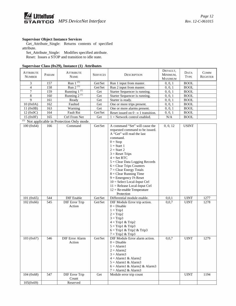
Supervisor Object Instance Services Get_Attribute_Single: Returns contents of specified attribute. Set_Attribute_Single: Modifies specified attribute. Reset: Issues a STOP and transition to idle state.
Supervisor Class (0x29), Instance (1) Attributes
ATTRIBUTE NUMBER
PARAM ATTRIBUTE
NAME SERVICES DESCRIPTION
DEFAULT, MINIMUM, MAXIMUM
DATA TYPE
COMM REGISTER
3 157 Run 1 (1) Get/Set Run 1 input from master. 0, 0, 1 BOOL 4 158 Run 2 (1) Get/Set Run 2 input from master. 0, 0, 1 BOOL 7 159 Running 1 (1) Get Starter Sequencer is running. 0, 0, 1 BOOL 8 160 Running 2 (1) Get Starter Sequencer is running. 0, 0, 1 BOOL 9 161 Ready Get Starter is ready. 0, 0, 1 BOOL
10 (0x0A) 162 Faulted Get One or more trips present. 0, 0, 1 BOOL 11 (0x0B) 163 Warning Get One or more alarms present. 0, 0, 1 BOOL 12 (0x0C) 164 Fault Rst Get/Set Reset issued on 0 1 transition. 0, 0, 1 BOOL 15 (0x0F) 165 Ctrl From Net Get 1 = Network control enabled. N/A BOOL
(1) Not applicable in Protection Only mode. 100 (0x64) 166 Command Get/Set A command “Set” will cause the
requested command to be issued. A “Get” will read the last command. 0 = Stop 1 = Start 1 2 = Start 2 3 = Reset Trips 4 = Set RTC 5 = Clear Data Logging Records 6 = Clear Trips Counters 7 = Clear Energy Totals 8 = Clear Running Time 9 = Emergency I²t Reset 10 = Select Local-Input Ctrl 11 = Release Local-Input Ctrl 12 = Re-enable Temperature
109 (0x6D) 170 OPI Control Get/Set 0 = Enable OPI motor control 1 = Disable OPI motor control
0, 0, 1 UINT 240
110 (0x6E) 171 OPI Local Get/Set 0 = Enable OPI to select LOCAL 1 = OPI cannot select LOCAL
0, 0, 1 UINT 241
111 (0x6F) 172 OPI Trips Get Number of OPI comm trips. UINT 1185 112 (0x70) 173 RemGrpDig Get/ Set Bind digital start sources to the
REMOTE group. 0 = Include in Group 1 = Do not Include in Group
0, 0, 1 UINT 242
113 (0x71) 174 RemGrpNet Get/Set Bind OPI start sources to the REMOTE group. 0 = Include in Group 1 = Not in Group
0, 0, 1 UINT 243
114 (0x72) 175 RemGrpOPI Get/Set Bind Net start sources to the REMOTE group. 0 = Include in Group 1 = Not in Group
0, 0, 1 UINT 244
115 (0x73) 176 Starter Type Get/Set Selects the starter type. 0 = Protection Only 1 = Full Voltage Non-Reversing 2 = Adjustable-Speed Drive 3 = Soft Start 4 = Full Voltage Reversing 5 = Two Speed * 6 = Reactor/Resistor Closed
Transition 7 = Reactor/Resistor Open
Transition 8 = Slip Ring 9 = Soft Start With Bypass 10 = Port Winding * 11 = Double Delta * 12 = Autotransformer 13 = Two Winding * 14 = Wye-Delta Open Trans. * 15 = Wye-Delta Closed Trans. * * Uses Full-Load Current 2
0, 0, 15 UINT 248
116 (0x74) 177 Start Time Get/Set See Main Product Manual 20, 0.1, 500 REAL 249/250 117 (0x75) 178 Start Delay 1 Get/Set See Main Product Manual 20, 0.1, 500 REAL 251/252 118 (0x76) 179 Start Delay 2 Get/Set See Main Product Manual 20, 0.1, 500 REAL 253/254 119 (0x77) 180 Start Delay 3 Get/Set See Main Product Manual 20, 0.1, 500 REAL 255/256
Page 14 MPS DeviceNet Interface Rev. 12-C-061015
Supervisor Class (0x29), Instance (1) Attributes (Continued)
121 (0x79) 182 Backspin Delay Get/Set Backspin delay in seconds. 5, 0.1, 100 REAL 258/259 122 (0x7A) 183 Sequence Trips Get Number of starter sequence trips UINT 1184 123 (0x7B) 184 Stop Count Get Number of trips caused by STOP
when starter type is set to Protection Only.
UINT 1186
124 (0x7C) 185 RY Status Trips Get Number of contactor status trips. UINT 1148 125 (0x7D) 186 Transfer Type Get/Set Soft-start transfer type:
0 = Time Transfer 1 = Current Transfer
0, 0, 1 UINT 260
126 (0x7E) 187 Transfer Level Get/Set Level in % FLA 1.25, 1.0, 3.0
REAL 261/262
127(0x7F) Local Start-OPI Get/Set Local Start Source – OPI 0, 0, 1 UINT 245 128 (0x80)
188 RY1 Function Get/Set Function Assigned to Relay 1
129 (0x81) 189 RY1 Mode Get/Set 0 = Fail Safe, 1 = Non Fail Safe 0, 0, 1 UINT 335 130 (0x82) 190 RY2 Function Get/ Set See Attribute 0x80 0, 0, 18 UINT 336 131 (0x83) 191 RY2 Mode Get/Set 0 = Fail Safe, 1 = Non Fail Safe 0, 0, 1 UINT 337 132 (0x84) 192 RY3 Function Get/ Set See Attribute 0x80 0, 0, 18 UINT 338 133 (0x85) 193 RY3 Mode Get/Set 0 = Fail Safe, 1 = Non Fail Safe 0, 0, 1 UINT 339 134 (0x86) 194 RY4Function Get/ Set See Attribute 0x80 0, 0, 18 UINT 340 135 (0x87) 195 RY4 Mode Get/Set 0 = Fail Safe, 1 = Non Fail Safe 0, 0, 1 UINT 341 136 (0x88) 196 RY5 Function Get/ Set See Attribute 0x80 0, 0, 18 UINT 342 137 (0x89) 197 RY5 Mode Get/Set 0 = Fail Safe, 1 = Non Fail Safe 0, 0, 1 UINT 343 138 (0x8A) 523 RY Pulse Time Get/Set Specifies the duration of the trip
pulse when the RY function is set to “Trip1 Pulse”.
0.25, 0.05, 10
REAL 344
144 (0x90) 198 TA Summary Get Trip, Alarm, Status Summary Bit 0: 1 = Trip (Trip1 or Trip3) Bit 1: 1 = Alarm (Alarm 1, 2, 3) Bit 2: 1 = Trip2 Bit 3: 1 = Interlocks Not Valid Bit 4: 1 = Start Lock Active Bit 5: 1 = Stop Input Active
WORD 1096
Page 15 MPS DeviceNet Interface Rev. 12-C-061015
Supervisor Class (0x29), Instance (1) Attributes (Continued)
ATTRIBUTE NUMBER
PARAM ATTRIBUTE
NAME SERVICES DESCRIPTION
DEFAULT, MINIMUM, MAXIMUM
DATA TYPE
COMM REGISTER
145 (0x91) 199 Motor Status Get Bit 0: 1 = I > Threshold Bit 1: 1 = 10% < I < 125% for
10 s Bit 2: 1 = Tach at Full Speed Bit 3: 1 = I > 120% FLA Bit 4: 1 = Temperature
Bypassed
WORD 1097
146 (0x92) 200 Starter Status Get 1 = Start 1 2 = Run 1 (Sequence Complete) 3 = Start 2 4 = Run 2 (Sequence Complete) 5 = Stop 6 = Backspin Timer Active
UINT 1098
147 (0x93) 201 Digital Inputs Get Bit 0: IN1 Voltage Detected Bit 1: IN2 Voltage Detected Bit 2: IN3 Voltage Detected Bit 3: IN4 Voltage Detected Bit 4: IN5 Voltage Detected Bit 5: IN6 Voltage Detected Bit 6: IN7 Voltage Detected
WORD 1099
148 (0x94) 202 Relay Outputs Get Bit 0: Relay 1 Energized Bit 1: Relay 2 Energized Bit 2: Relay 3 Energized Bit 3: Relay 4 Energized Bit 4: Relay 5 Energized
WORD 1100
149..151 Reserved 152 (0x98) 203 Trip/Alarm Msg 0 Get Trip and Alarm FIFO. See Main
Product Manual Appendix F T27. 255= No trip or alarm.
UINT 1104
153 (0x99) 204 Trip/Alarm Msg 1 Get Trip and Alarm FIFO. See Main Product Manual Appendix F T27. 255= No trip or alarm.
UINT 1105
154 (0x9A) 205 Trip/Alarm Msg 2 Get Trip and Alarm FIFO. See Main Product Manual Appendix F T27. 255= No trip or alarm.
UINT 1106
155 (0x9B) 206 Trip/Alarm Msg 3 Get Trip and Alarm FIFO. See Main Product Manual Appendix F T27. 255= No trip or alarm.
UINT 1107
156 (0x9C) 207 Trip/Alarm Msg 4 Get Trip and Alarm FIFO. See Main Product Manual Appendix F T27. 255= No trip or alarm.
UINT 1108
Page 16 MPS DeviceNet Interface Rev. 12-C-061015
3.7 OVERLOAD CLASS 0x2C Overload Object Class Services Get_Attribute_Single: Returns contents of specified attribute.
Overload Class (0x2C), Instance (0) Attributes
ATTRIBUTE NUMBER
ATTRIBUTE NAME
SERVICES DESCRIPTION DEFAULT, MINIMUM, MAXIMUM
DATA TYPE
1 Revision Get Revision of this object. 1 UINT 2 Max Instance Get Maximum number of instances. 1 UINT
103 (0x67) 4 K-Factor Get/Set Used in I²t Algorithm 6, 1, 10 REAL 11/12 104 (0x68) 5 LR Current Get/Set Locked Rotor Current (x FLA) 6, 1, 10 REAL 12/14 105 (0x69) 6 LR Time Cold Get/Set Locked Rotor Time Cold (s) 10, 0.2, 100 REAL 15/16 106 (0x6A) 7 LR Time Hot Get/Set Locked Rotor Time Hot (s) 5, 0.2, 100 REAL 17/18 107 (0x6B) 8 Cooling Factor Get/Set Multiples of Running Time
Constant 2, 0.1, 50 REAL 19/20
108 (0x6C) 9 Thermal Lock Level Get/Set Thermal Reset/Inhibit Level per Unit
117 (0x75) 18 System Voltage Get/Set Line-to-Line Voltage (kV) 0.6, 0.12, 25
REAL 227/228
118 (0x76) 19 Sync Speed Get/Set Motor Synchronous Speed (RPM)
1800, 100, 10k
REAL 229/230
119 (0x77) 20 Service Factor Get/Set Motor Service Factor 1, 1, 1.25 REAL 233/234 120 (0x78) 21 FLA Rating 2 Get/Set Full-Load Current #2 100, 1,
5000 REAL 235/236
121 (0x79) 22 Trip Count Get Counts Overload Trips UINT 1132 122 (0x7A) 474 Run-Mode Delay Get/Set Time delay defines when motor
is in run mode. 10, 5, 60 REAL 216/217
123(0x7B) 535 SPH Trip Action Get/Set Starts per hour trip action. 0,0,7 UINT 1270 124(0x7C) 536 SPH Alarm Action Get/Set Starts per hour alarm action. 0,0,7 UINT 1271 125(0x7D) 537 Starts Per Hour Get/Set Starts per hour setting.
0= 1 Start Per Hour 9= 10 Starts Per Hour
4,0,9 UINT 1272
126(0x7E) 538 Time Between Starts
Get/Set Time in minutes between starts. 0,0,500 REAL 1273/1274
127(0x7F) 539 SPH Trip Count Get Number of SPH trips. UINT 1193 128(0x80) 540 Overload Reset
Type Get/Set Thermal Overload Reset Type 0,0,2 UINT 26
144 (0x90) 23 IA Get Phase A Current (A) REAL 860/861 145 (0x91) 24 IB Get Phase B Current (A) REAL 862/863 146 (0x92) 25 IC Get Phase C Current (A) REAL 864/865 147 (0x93) 26 3IO Get Ground-Fault Current (A) REAL 866/867 148 (0x94) 27 Vab Get Line-to-Line Voltage (kV) REAL 868/869 149 (0x95) 28 Vbc Get Line-to-Line Voltage (kV) REAL 870/871 150 (0x96) 29 Vca Get Line-to-Line Voltage (kV) REAL 872/873 151 (0x97) 30 S Get Apparent Power (kVA) REAL 874/875 152 (0x98) 31 Q Get Reactive Power (kVAC) REAL 876/877 153 (0x99) 32 P Get Real Power (kW) REAL 878/879 154 (0x9A) 33 PF Get Power Factor 1 to 1 REAL 880/881 155 (0x9B) 34 Used I²t Get Used Thermal Capacity (%) REAL 882/883 156 (0x9C) 35 Thermal Trend Get Thermal Trend (%) REAL 886/887 157 (0x9D) 36 +Seq I Get Positive Sequence Current (Pu) REAL 888/889 158 (0x9E) 37 -Seq I Get Negative Sequence Current (Pu) REAL 890/891 159 (0x9F) 38 Unbalance I Get Current Unbalance (Pu) REAL 892/893 160 (0xA0) 39 Frequency Get Frequency (from Vab) REAL 966/967 161 (0xA1) 40 -Seq V Get Negative Sequence Voltage (Pu) REAL 896/897 162 (0xA2) 41 Unbalance V Get Voltage Unbalance (Pu) REAL 898/899 163 (0xA3) 42 Run Time Get Running time in seconds UDINT 1210 164 (0xA4) 43 KWs Get KW seconds LREAL 1212..15 165 (0xA5) 44 KVAs Get KVA seconds LREAL 1216..19 166 (0xA6) 45 KVARs Get KVAR seconds LREAL 1220..23 167(0xA7) 541 DIF Ia Get Differential current, phase A REAL 1224/1225 168(0xA8) 542 DIF Ib Get Differential current, phase B REAL 1226/1227 168(0xA9) 543 DIF Ic Get Differential current, phase C REAL 1228/1229
Page 18 MPS DeviceNet Interface Rev. 12-C-061015
3.8 SET POINT CLASS 0x64 Set Point Object Class Services Get_Attribute_Single: Returns contents of specified attribute.
Set Point Class (0x64), Instance (0) Attributes
ATTRIBUTE NUMBER
ATTRIBUTE NAME
SERVICES DESCRIPTION DEFAULT, MINIMUM, MAXIMUM
DATA TYPE
1 Revision Get Revision of this object. 5 UINT 2 Max Instance Get Maximum number of instances. 22 UINT
Set Point Object Instances Set Point Object Instance Services Get_Attribute_Single: Returns contents of specified attribute. Set_Attribute_Single: Modifies specified attribute. The set point class consists of seven attributes. Each set-point instance may use some or all of these attributes. Attribute 1 - Trip Action Specifies the action to take on a trip. 0 = Disable 1 = Trip1 (1) 2 = Trip2 3 = Trip3 4 = Trip1 & Trip2 5 = Trip1 & Trip3 6 = Trip1 & Trip2 & Trip3 7 = Trip2 & Trip3
Attribute 2 - Alarm Action Specifies the action to take on an alarm. 0 = Disable 1 = Alarm1 2 = Alarm2 3 = Alarm3 4 = Alarm1 & Alarm2 5 = Alarm1 & Alarm3 6 = Alarm1 & Alarm2 & Alarm3 7 = Alarm2 & Alarm3 Attribute 3 - Trip Level Attribute 4 - Trip Delay Attribute 5 - Alarm Level Attribute 6 - Alarm Delay Attribute 7 - Trip Counter for the set point (1) Initiates a STOP when a starter function is enabled.
3.9 ACCELERATION CLASS 0x65 Motor speed is measured using a digital tach connected to Digital Input 8, or a 4–20 mA speed sensor. This class defines parameters for speed protection. Acceleration Object Class Services Get_Attribute_Single: Returns contents of specified attribute.
Acceleration Class (0x65), Instance (0) Attributes
ATTRIBUTE NUMBER
ATTRIBUTE NAME
SERVICES DESCRIPTION DEFAULT, MINIMUM, MAXIMUM
DATA TYPE
1 Revision Get Revision of this object. 1 UINT 2 Max Instance Get Maximum number of instances. 1 UINT
1 146 Accel Action Get/Set Specifies the action to take on a trip. 0 = Disable 1 = Trip1(1) 2 = Trip2 3 = Trip3 4 = Trip1 & Trip2 5 = Trip1 & Trip3 6 = Trip1 & Trip2 & Trip3 7 = Trip2 & Trip3 (1) Initiates a STOP when a starter function is enabled.
1, 0, 7 UINT 152
2 147 Speed1 Get/Set Motor must reach Speed1 in the time defined by Time1. (%FS)
30, 1, 100 REAL 153/154
3 148 Time1 Get/Set Defines the time when Speed1 must be reached. (s)
5, 1, 1000 REAL 155/156
4 149 Speed2 Get/Set Motor must reach Speed2 in the time defined by Time2. (%FS)
60, 1, 100 REAL 157/158
5 150 Time2 Get/Set Defines the time when Speed2 must be reached. (s)
10, 1, 1000 REAL 159/160
6 151 Speed3 Get/Set Motor must reach Speed3 in the time defined by Time3. (%FS)
90, 1, 100 REAL 161/164
7 152 Time3 Get/Set Defines the time when Speed3 must be reached. (s)
15, 1, 1000 REAL 163/164
8 153 Tach Enable Get/Set Enables speed measurement even if protection is disabled. 0 = Enabled, 1 = Disabled
1, 0, 1 UINT 330
9 154 Pulses Per Rev Get/Set Sets the number of pulses per revolution for digital tach.
60, 1, 100 REAL 331/332
10 (0x0A) 155 Tach Speed Get Motor Speed from Tach REAL 900/901 11 (0x0B) 156 Trip Count Get Counts Number of Accel Trips UINT 1147
Page 24 MPS DeviceNet Interface Rev. 12-C-061015
3.10 DIGITAL INPUT CLASS 0x66 Digital Input Object Class Services Get_Attribute_Single: Returns contents of specified attribute.
Digital Input Class (0x66), Instance (0) Attributes
ATTRIBUTE NUMBER
ATTRIBUTE NAME
SERVICES DESCRIPTION DEFAULT, MINIMUM, MAXIMUM
DATA TYPE
1 Revision Get Revision of this object. 1 UINT 2 Max Instance Get Maximum number of instances. 7 UINT
Digital Input Object Instance Services Get_Attribute_Single: Returns contents of specified attribute. Set_Attribute_Single: Modifies specified attribute. The digital-input class consists of 5 attributes. Attribute 1 - Function Selects the function of the digital input. 0 = Input not used 1 = Start1 (N.O. Contact) 2 = Start2 (N.O. Contact) 3 = Stop (N.C. Contact) 4 = Starter RLYA contactor status 5 = Starter RLYB contactor status 6 = Starter RLYC contactor status 7 = Starter RLYD contactor status 8 = Interlock (N.C.) 9 = Trip1 (N.C.) 10 = Reset (N.O.) 11 = Local Select 12 = Local Start1 13 = Local Start2 14 = 2-Wire Start1 15 = 2-Wire Start2 16 = FLA2 Select 17 = Limit1 Select 18 = Limit2 Select 19 = Reduced OC
Attribute 2 - Bypass Enable/Disable Attribute applies when the input function is trip. When enabled, the input is bypassed for the time defined by the Bypass Delay when a motor is started using starter control. 0 = Enable, 1 = Disable Attribute 3 - Bypass Delay Defines the Trip bypass time duration on start. Attribute 4 - Trip Delay Applies only to the trip function. Attribute 5 - Trip Count The trip counter only applies to the trip function.
3.11 ANALOG I/O CLASS 0x67 Analog I/O Object Instance Services Get_Attribute_Single: Returns contents of specified attribute.
Analog I/O Class (0x67), Instance (0) Attributes
ATTRIBUTE NUMBER
ATTRIBUTE NAME
SERVICES DESCRIPTION DEFAULT, MINIMUM, MAXIMUM
DATA TYPE
1 Revision Get Revision of this object. 1 UINT 2 Max Instance Get Maximum number of instances. 1 UINT
Analog I/O Object Instance Services Get_Attribute_Single: Returns contents of specified attribute. Set_Attribute_Single: Modifies specified attribute.
Analog I/O Class (0x67), Instance (1) Attributes
ATTRIBUTE NUMBER
PARAM ATTRIBUTE
NAME SERVICES DESCRIPTION
DEFAULT, MINIMUM, MAXIMUM
DATA TYPE
COMM REGISTER
1 243 Analog In Type Get/Set Defines the analog-input type. 0 = Disabled 1 = Generic (Trip1, Alarm1
enabled) 2 = ASD sets sampling
frequency 3 = Motor speed
0, 0, 3 UINT 350
2 244 High Trip Get/Set Sets high trip level for generic input type. (mA)
16, 0.1, 20 REAL 351/352
3 245 Low Trip Get Set Sets low trip level for generic input type. (mA)
7, 0.1, 20 REAL 353/354
4 246 Trip Delay Get/Set Applies to generic type. (s) 5, 0.01, 100 REAL 355/356 5 247 High Alarm Get/Set Sets high alarm level for generic
input type. (mA) 14, 0.1, 20 REAL 357/358
6 248 Low Alarm Get/Set Sets low alarm level for generic input type (mA)
9, 0.1, 20 REAL 359/360
7 249 Alarm Delay Get/Set Applies to Generic Type (s) 1, 0.01, 100 REAL 361/362 8 250 ASD_4mA Get/Set Applies to type 2 input.
Frequency corresponding to 4 mA input. (Hz)
10, 0, 70 REAL 363/364
Page 27 MPS DeviceNet Interface Rev. 12-C-061015
Analog I/O Class (0x67), Instance (1) Attributes (Continued)
ATTRIBUTE NUMBER
PARAM ATTRIBUTE
NAME SERVICES DESCRIPTION
DEFAULT, MINIMUM, MAXIMUM
DATA TYPE
COMM REGISTER
9 251 ASD_20mA Get/Set Applies to type 2 input. Frequency corresponding to 20 mA input. (%FS)
10, 0, 70 REAL 365/366
10 (0x0A) 252 Tach_4mA Get/Set Applies to type 3 input. % Speed corresponding to 4 mA input. (%FS)
10, 0, 100 REAL 367/368
11 (0x0B) 253 Tach_20mA Get/Set Applies to type 3 input. % Speed corresponding to 20 mA input. (%FS)
100, 0, 100 REAL 369/370
12 (0x0C) 254 Out Param Get/Set Specifies the analog output parameter 0 = Phase Current 1 = Earth Leakage 2 = Thermal Capacity 3 = Max Stator RTD 4 = Max Bearing RTD 5 = Max Load RTD 6 = Max Ambient RTD 7 = Voltage 8 = Unbalance (I) 9 = Power Factor 10 = Real Power 11 = Reactive Power 12 = Apparent Power 13 = Zero (4 mA) 14 = Full Scale (20 mA) 15= Speed 16 = Differential Current
0, 0, 16 UINT 373/374
13 (0x0D) 255 Reading Get Analog input reading. (mA) 0, 0, 20 REAL 884/885 14 (0x0E) 256 High Trips Get Input-High Trip Count UINT 1140 15 (0x0F) 257 Low Trips Get Input-Low Trip Count UINT 1141
3.12 RTD MODULE CLASS 0x68 RTD Module Object Class Services Get_Attribute_Single: Returns contents of specified attribute. Set_Attribute_Single: Modifies specified attribute.
Class 0x68, Instance 0, Attributes
ATTRIBUTE NUMBER
PARAM ATTRIBUTE
NAME SERVICES DESCRIPTION
DEFAULT, MINIMUM, MAXIMUM
DATA TYPE
COMM REGISTER
1 Revision Number Get Revision number of this class. 1 UINT 2 Max Instance Get Maximum number of RTD
modules. 3 UINT
100 (0x64) 258 Modules Used Get/Set Specifies the number of RTD modules used.
0, 0, 3 UINT 390
Page 28 MPS DeviceNet Interface Rev. 12-C-061015
Class 0x68, Instance 0, Attributes (Continued)
ATTRIBUTE NUMBER
PARAM ATTRIBUTE
NAME SERVICES DESCRIPTION
DEFAULT, MINIMUM, MAXIMUM
DATA TYPE
COMM REGISTER
101 (0x65) 259 Sensor Trip Action Get/Set Specifies trip action to take on a sensor error. 0 = Disable Trips 1 = Trip1(1) 2 = Trip2 3 = Trip3 4 = Trip1 & Trip2 5 = Trip1 & Trip3 6 = Trip1 & Trip2 & Trip3 7 = Trip2 & Trip3 (1) Initiates a STOP when a starter function is enabled.
Get/Set Specifies trip action to take on a module error. Action list is the same as Attribute 9.
0, 0, 7 UINT 389
104 (0x68) 262 Module Error Alarm Action
Get/Set Specifies alarm action to take on a module error. Action list is the same as Attribute A.
1, 0, 7 UINT 380
105 (0x69) 263 Module1 Comm Trip Count
Get Number of module1 communication-error trips.
UINT 1180
106 (0x6A) 264 Module2 Comm Trip Count
Get Number of module2 communication-error trips.
UINT 1181
107 (0x6B) 265 Module3 Comm Trip Count
Get Number of module3 communication-error trips.
UINT 1182
108 (0x6C) 266 Sensor Trip Count Get Number of RTD sensor trips UINT 1183 109 (0x6D) 267 HMC Enable Get/Set Hot Motor Compensation
control. 0 = Enable, 1 = Disable
UINT 550
110 (0x6E) 268 HMC Max Bias Get/Set Stator temperature (°C) where compensation ends at 100% I²t.
150, 40, 200
REAL 551/552
111 (0x6F) 269 HMC Min Bias Get/Set Stator temperature (°C) where compensation begins at 0% I²t.
40, 40, 200 REAL 553/554
112 (0x70) 270 Max Stator Temp Get Max Stator Temperature (°C) REAL 950/951 113 (0x71) 271 Max Bearing Temp Get Max Bearing Temperature (°C) REAL 952/953 114 (0x72) 272 Max Load Temp Get Max Load Temperature (°C) REAL 954/955 115 (0x73) 273 Max Amb Temp Get Max Ambient Temperature (°C) REAL 956/957 116 (0x74) 274 Min Stator Temp Get Min Stator Temperature (°C) REAL 958/959 117 (0x75) 275 Min Bearing Temp Get Min Bearing Temperature (°C) REAL 960/961 118 (0x76) 276 Min Load Temp Get Min Load Temperature (°C) REAL 962/963 119 (0x77) 277 Min Ambient Temp Get Min Ambient Temperature (°C) REAL 964/965
Page 29 MPS DeviceNet Interface Rev. 12-C-061015
Class 0x68, Instance 0, Attributes (Continued)
ATTRIBUTE NUMBER
PARAM ATTRIBUTE
NAME SERVICES DESCRIPTION
DEFAULT, MINIMUM, MAXIMUM
DATA TYPE
COMM REGISTER
120 (0x78) 524 Temperature Trip Action
Get/Set Specifies trip action to take on a sensor error. 0 = Disable Trips 1 = Trip1(1) 2 = Trip2 3 = Trip3 4 = Trip1 & Trip2 5 = Trip1 & Trip3 6 = Trip1 & Trip2 & Trip3 7 = Trip2 & Trip3 (1) Initiates a STOP when a starter function is enabled.
RTD Module Object Instance Services Get_Attribute_Single: Returns contents of specified attribute. Set_Attribute_Single: Modifies specified attribute. Object Instance Attributes 1 to 8 define the RTD type. Selecting an RTD will enable trip and alarm set points. The trip action is fixed as Trip1 and the alarm action is fixed as Alarm1. 0 = RTD Disabled 1 = Platinum 100 ohm 2 = Nickel 100 ohm 3 = Nickel 120 ohm 4 = Copper 10 ohm Object Instance Attributes 0x09 to 0x10 define the RTD function. 0 = Stator 1 = Bearing 2 = Load 3 = Ambient
4= Stator Voting 5= Bearing Voting 6= Load Voting 7= Ambient Voting Object Instance Attributes 0x11 to 0x20 define the trip and alarm settings in degrees C. The trip action is fixed as Trip1 and the alarm action is fixed as Alarm1. Object Instance Attributes 0x21 to 0x28 define an 18-character name. Object Instance Attributes 0x29 to 0x30 are temperature readings. Object Instance Attributes 0x31 to 0x38 are the trip counters for each of the RTD's.
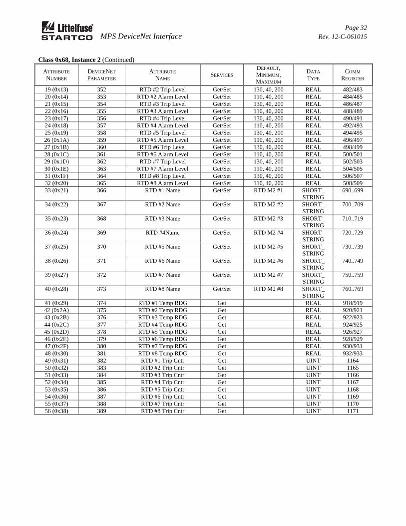
41 (0x29) 430 RTD #1 Temp RDG Get REAL 934..935 42 (0x2A) 431 RTD #2 Temp RDG Get REAL 936..937 43 (0x2B) 432 RTD #3 Temp RDG Get REAL 938..939 44 (0x2C) 433 RTD #4 Temp RDG Get REAL 940..941 45 (0x2D) 434 RTD #5 Temp RDG Get REAL 942..943 46 (0x2E) 435 RTD #6 Temp RDG Get REAL 944..945
Page 34 MPS DeviceNet Interface Rev. 12-C-061015
Class 0x68, Instance 3 (Continued)
ATTRIBUTE NUMBER
DEVICENET PARAMETER
ATTRIBUTE NAME
SERVICES DEFAULT, MINIMUM, MAXIMUM
DATA TYPE
COMM REGISTER
47 (0x2F) 436 RTD #7 Temp RDG Get REAL 946/947 48 (0x30) 437 RTD #8 Temp RDG Get REAL 948/949 49 (0x31) 438 RTD #1 Trip Cntr Get UINT 1172 50 (0x32) 439 RTD #2 Trip Cntr Get UINT 1173 51 (0x33) 440 RTD #3 Trip Cntr Get UINT 1174 52 (0x34) 441 RTD #4 Trip Cntr Get UINT 1175 53 (0x35) 442 RTD #5 Trip Cntr Get UINT 1176 54 (0x36) 443 RTD #6 Trip Cntr Get UINT 1177 55 (0x37) 444 RTD #7 Trip Cntr Get UINT 1178 56 (0x38) 445 RTD #8 Trip Cntr Get UINT 1179
3.13 RTC CLASS 0x69 RTC Object Class Services Get_Attribute_Single: Returns contents of specified attribute.
RTC Class (0x69), Instance (0) Attributes
ATTRIBUTE NUMBER
ATTRIBUTE NAME
SERVICES DESCRIPTION DEFAULT, MINIMUM, MAXIMUM
DATA TYPE
1 Revision Get Revision of this object 1 UINT 2 Max Instance Get Maximum number of instances 1 UINT
RTC Object Class Services Get_Attribute_Single: Returns contents of specified attribute. Set_Attribute_Single: Modifies specified attribute.
2 447 IRIG Min Offset Get/Set RTC Min = IRIG Min + IRIG Min Offset
0, 0, 23 REAL 570/571
3 448 RTC Date Get Number of Days since 1972-01-01
DATE 574/575
4 449 RTC Time Get Number of Milliseconds since 00:00:00:00.000
TIME OF DAY
576/577
5 450 RTC Set Get/Set (1)
String Used to Set the Date and Time YY/MM/DD-HH:MM:SS
SHORT_ STRING
580/589
(1) Time value is not activated until a SET RTC command is issued using Class 0x29, Instance 1, Attribute 0x64.
Page 35 MPS DeviceNet Interface Rev. 12-C-061015
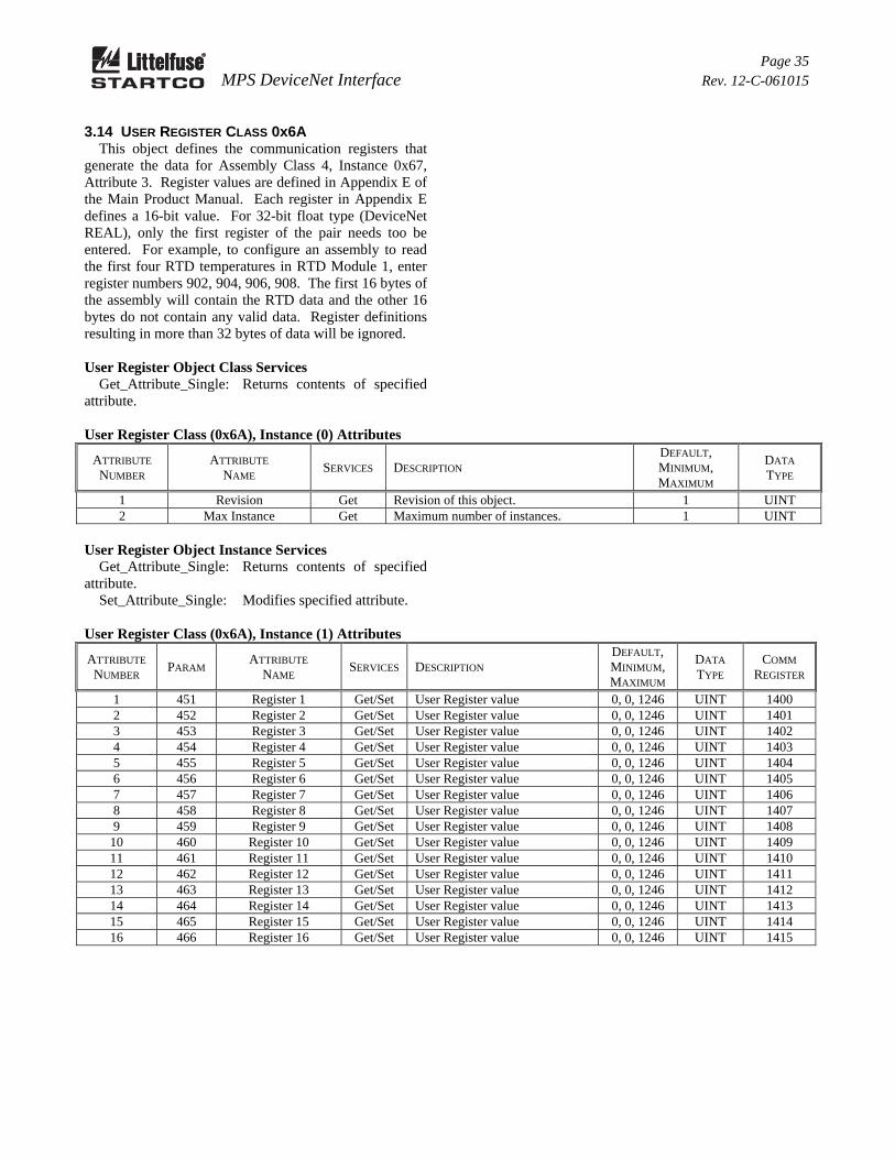
3.14 USER REGISTER CLASS 0x6A This object defines the communication registers that generate the data for Assembly Class 4, Instance 0x67, Attribute 3. Register values are defined in Appendix E of the Main Product Manual. Each register in Appendix E defines a 16-bit value. For 32-bit float type (DeviceNet REAL), only the first register of the pair needs too be entered. For example, to configure an assembly to read the first four RTD temperatures in RTD Module 1, enter register numbers 902, 904, 906, 908. The first 16 bytes of the assembly will contain the RTD data and the other 16 bytes do not contain any valid data. Register definitions resulting in more than 32 bytes of data will be ignored. User Register Object Class Services Get_Attribute_Single: Returns contents of specified attribute.
User Register Class (0x6A), Instance (0) Attributes
ATTRIBUTE NUMBER
ATTRIBUTE NAME
SERVICES DESCRIPTION DEFAULT, MINIMUM, MAXIMUM
DATA TYPE
1 Revision Get Revision of this object. 1 UINT 2 Max Instance Get Maximum number of instances. 1 UINT
User Register Object Instance Services Get_Attribute_Single: Returns contents of specified attribute. Set_Attribute_Single: Modifies specified attribute.
User Register Class (0x6A), Instance (1) Attributes
ATTRIBUTE NUMBER
PARAM ATTRIBUTE
NAME SERVICES DESCRIPTION
DEFAULT, MINIMUM, MAXIMUM
DATA TYPE
COMM REGISTER
1 451 Register 1 Get/Set User Register value 0, 0, 1246 UINT 1400 2 452 Register 2 Get/Set User Register value 0, 0, 1246 UINT 1401 3 453 Register 3 Get/Set User Register value 0, 0, 1246 UINT 1402 4 454 Register 4 Get/Set User Register value 0, 0, 1246 UINT 1403 5 455 Register 5 Get/Set User Register value 0, 0, 1246 UINT 1404 6 456 Register 6 Get/Set User Register value 0, 0, 1246 UINT 1405 7 457 Register 7 Get/Set User Register value 0, 0, 1246 UINT 1406 8 458 Register 8 Get/Set User Register value 0, 0, 1246 UINT 1407 9 459 Register 9 Get/Set User Register value 0, 0, 1246 UINT 1408
10 460 Register 10 Get/Set User Register value 0, 0, 1246 UINT 1409 11 461 Register 11 Get/Set User Register value 0, 0, 1246 UINT 1410 12 462 Register 12 Get/Set User Register value 0, 0, 1246 UINT 1411 13 463 Register 13 Get/Set User Register value 0, 0, 1246 UINT 1412 14 464 Register 14 Get/Set User Register value 0, 0, 1246 UINT 1413 15 465 Register 15 Get/Set User Register value 0, 0, 1246 UINT 1414 16 466 Register 16 Get/Set User Register value 0, 0, 1246 UINT 1415
Page 36 MPS DeviceNet Interface Rev. 12-C-061015
3.15 DATA LOGGING CLASS 0x6B This object is used to access one of 64 data-logging records. The Record Selector value defines the record that is displayed. Record Head indicates the record number for the latest record. Data Logging Object Class Services Get_Attribute_Single: Returns contents of specified attribute.
Data Logging Class (0x6B), Instance (0) Attributes
ATTRIBUTE NUMBER
ATTRIBUTE NAME
SERVICES DESCRIPTION DEFAULT, MINIMUM, MAXIMUM
DATA TYPE
1 Revision Get Revision of this object. 1 UINT 2 Max Instance Get Maximum number of instances. 1 UINT
Data Logging Object Instance Services Get_Attribute_Single: Returns contents of specified attribute. Set_Attribute_Single: Modifies specified attribute.
Data Logging Class (0x6B), Instance (1) Attributes
ATTRIBUTE NUMBER
PARAM ATTRIBUTE
NAME SERVICES DESCRIPTION
DEFAULT, MINIMUM, MAXIMUM
DATA TYPE
COMM REGISTER
1 475 Record Count Get Number of captured records since the last time the event records were cleared.
0, 0, 65535 UINT 973
2 476 Record Head Get Points to next record. Latest record at Record Head minus 1.
0, 0, 63 UINT 974
3 477 Record Selector Get/Set Selects the record for which the data is displayed in this instance.
0, 0, 63 UINT 975
4 478 Record Date Get The date when the record was captured.
0, 0, 65535 DATE 976/977
5 479 Record Time Get Time-of-Day the record was captured.
0, 0, 86399999
TOD 978/979
6 480 Record Type Get Specifies the trigger source: 0 = Record Empty 1 = Triggered by start 2 = Triggered by trip
0, 0, 2 UINT 980
7 481 Trip Code Get See Main Product Manual Appendix F T27 for a list of trip codes. 255 = No Trip or Alarm.
0, 0, 255 UINT 981
8 482 IA Get Phase A Current (A)(1) Real 982 9 483 IB Get Phase B Current (A)(1) Real 984
10 (0x0A) 484 IC Get Phase C Current (A)(1) Real 986 11 (0x0B) 485 3IA Get Ground-Fault Current (A)(1) Real 988 12 (0x0C) 486 Vab Get Line-to-Line Voltage (kV)(1) Real 990 13 (0x0D) 487 Vbc Get Line-to-Line Voltage (kV)(1) Real 992 14 (0x0E) 488 Vca Get Line-to-Line Voltage (kV)(1) Real 994 15 (0x0F) 489 Frequency Get Frequency in Hz Real 1053/1054 16 (0x10) 490 S Get Apparent Power (kVA) Real 1055/1056 17 (0x11) 491 P Get Real Power (kW) Real 1057/1058 18 (0x12) 492 Q Get Reactive Power (kVAR) Real 1059/1060 19 (0x13) 493 PF Get Power Factor (-1, +1) Real 1061/1062 20 (0x14) 494 Ain Get Analog Input (mA) Real 996/997 21 (0x15) 495 Unbalance I Get Current Unbalance (pu)(1) Real 998/999 22 (0x16) 496 Unbalance V Get Voltage Unbalance (pu)(1) Real 1000/1001
Page 37 MPS DeviceNet Interface Rev. 12-C-061015
Data Logging Class (0x6B), Instance (1) Attributes (Continued)
ATTRIBUTE NUMBER
PARAM ATTRIBUTE
NAME SERVICES DESCRIPTION
DEFAULT, MINIMUM, MAXIMUM
DATA TYPE
COMM REGISTER
23 (0x17) 497 Start Time Get Start time in seconds. Only valid for start-type records.
UINT 1002
24 (0x18) 498 I²t Used Get For start records this is the I²t used during a start.
REAL 1003/1004
32 (0x20) 499 M1 RTD1 Get RTD Temperature Reading (ºC) REAL 1005/1006 33 (0x21) 500 M1 RTD2 Get RTD Temperature Reading (ºC) REAL 1007/1008 34 (0x22) 501 M1 RTD3 Get RTD Temperature Reading (ºC) REAL 1009/1010 35 (0x23) 502 M1 RTD4 Get RTD Temperature Reading (ºC) REAL 1011/1012 36 (0x24) 503 M1 RTD5 Get RTD Temperature Reading (ºC) REAL 1013/1014 37 (0x25) 504 M1 RTD6 Get RTD Temperature Reading (ºC) REAL 1015/1016 38 (0x26) 505 M1 RTD7 Get RTD Temperature Reading (ºC) REAL 1017/1018 39 (0x27) 506 M1 RTD8 Get RTD Temperature Reading (ºC) REAL 1019/1020 40 (0x28) 507 M2 RTD1 Get RTD Temperature Reading (ºC) REAL 1021/1022 41 (0x29) 508 M2 RTD2 Get RTD Temperature Reading (ºC) REAL 1023/1024 42 (0x2A) 509 M2 RTD3 Get RTD Temperature Reading (ºC) REAL 1025/1026 43 (0x2B) 510 M2 RTD4 Get RTD Temperature Reading (ºC) REAL 1027/1028 44 (0x2C) 511 M2 RTD5 Get RTD Temperature Reading (ºC) REAL 1029/1030 45 (0x2D) 512 M2 RTD6 Get RTD Temperature Reading (ºC) REAL 1031/1032 46 (0x2E) 513 M2 RTD7 Get RTD Temperature Reading (ºC) REAL 1033/1034 47 (0x2F) 514 M2 RTD8 Get RTD Temperature Reading (ºC) REAL 1035/1036 48 (0x30) 515 M3 RTD1 (2) Get RTD Temperature Reading (ºC) REAL 1037/1038 49 (0x31) 516 M3 RTD2 (3) Get RTD Temperature Reading (ºC) REAL 1039/1040 50 (0x32) 517 M3 RTD3 (4) Get RTD Temperature Reading (ºC) REAL 1041/1042 51 (0x33) 518 M3 RTD4 (5) Get RTD Temperature Reading (ºC) REAL 1043/1044 52 (0x34) 519 M3 RTD5 (5) Get RTD Temperature Reading (ºC) REAL 1045/1046 53 (0x35) 520 M3 RTD6 (5) Get RTD Temperature Reading (ºC) REAL 1047/1048 54 (0x36) 521 M3 RTD7 (5) Get RTD Temperature Reading (ºC) REAL 1049/1050 55 (0x37) 522 M3 RTD8 (5) Get RTD Temperature Reading (ºC) REAL 1051/1052
(1) For start records, current and unbalance are maximum values recorded during the start. Voltages are the minimum values recorded during the start.
(2) Phase A differential current for firmware > 2.30 (3) Phase B differential current for firmware > 2.30 (4) Phase C differential current for firmware > 2.30 (5) Ignore this value for firmware > 2.30
Page 38 MPS DeviceNet Interface Rev. 12-C-061015
APPENDIX A MPS DEVICENET EDS FILES
MPS FIRMWARE EDS FILES EDS FILE DATE 3.11 to Present 4.400 03-19-2013
2.61 to 3.10 4.300 03-09-2009
2.42 to 2.60 4.200 08-28-2007
1.84 to 2.41 4.100 11-13-2004
Page 39 MPS DeviceNet Interface Rev. 12-C-061015
APPENDIX B MPS DEVICENET INTERFACE REVISION HISTORY
MANUAL RELEASE DATE MANUAL REVISION June 10, 2015 12-C-061015
March 21, 2014 12-B-032114
August 20, 2013 12-A-082013 MANUAL REVISION HISTORY REVISION 12-C-061015 Added RTD Module Set Point Class, Instance 0, Attributes 120 and 121. REVISION 12-B-032114 Updated Set Point Class, Instance 0 default, minimum and maximum. Added Underpower and Reversepower instances. REVISION 12-A-082013 Updated Attribute 127 (0x7F) on page 14. Added Appendix A, Appendix B.