84
MSC.Marc 2003 + Fuel Cell Applications

MSC.Marc 2003+
Fuel Cell Applications
Pacific NorthwestNational Laboratory
ContentsMeshing/RemeshingAnalysis of Composite Materials (shell/solid)Fracture Mechanics CapabilitiesHeat Transfer and Coupled Thermal StressesRunning Jobs in ParallelFluidsUser Subroutines Future Work PEN Fuel Cell Modeling
Meshing/Remeshing
Pacific NorthwestNational Laboratory
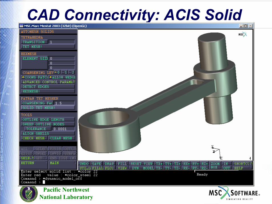
CAD Connectivity: ACIS Solid

Pacific NorthwestNational Laboratory
Convert to Surfaces

Pacific NorthwestNational Laboratory
Automatic Meshing

Local Remeshing
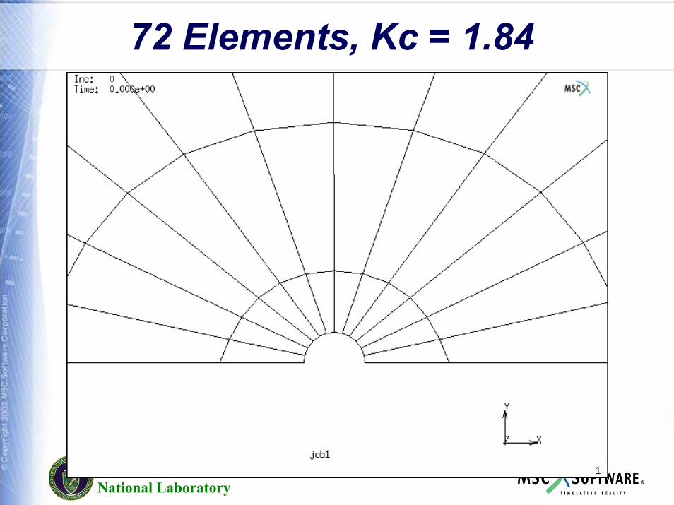
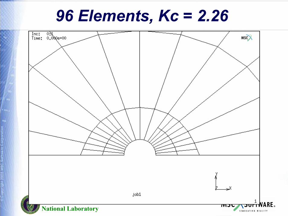
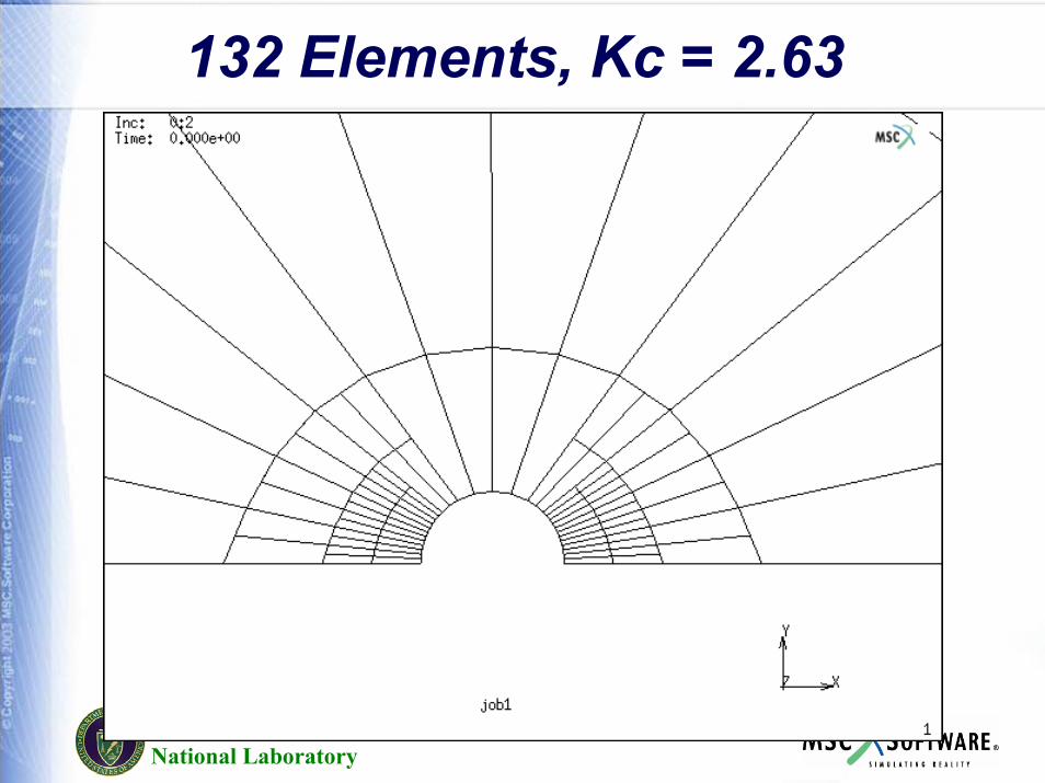
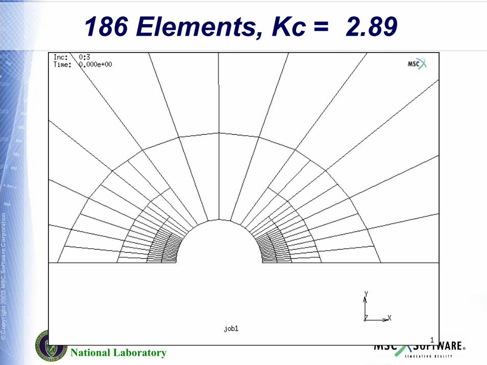
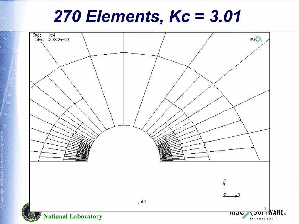
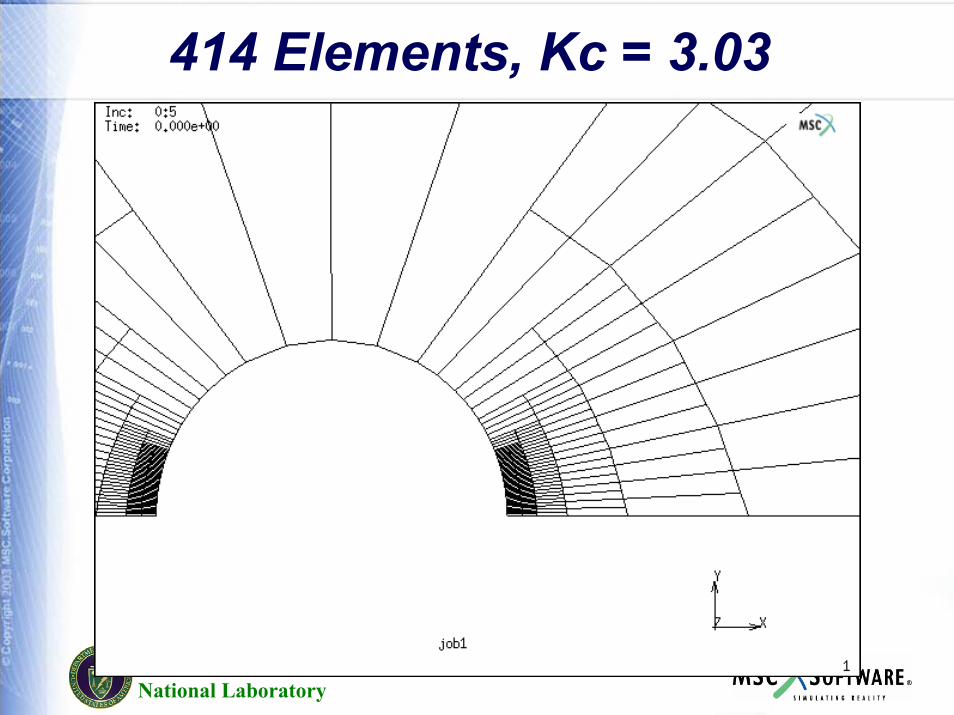
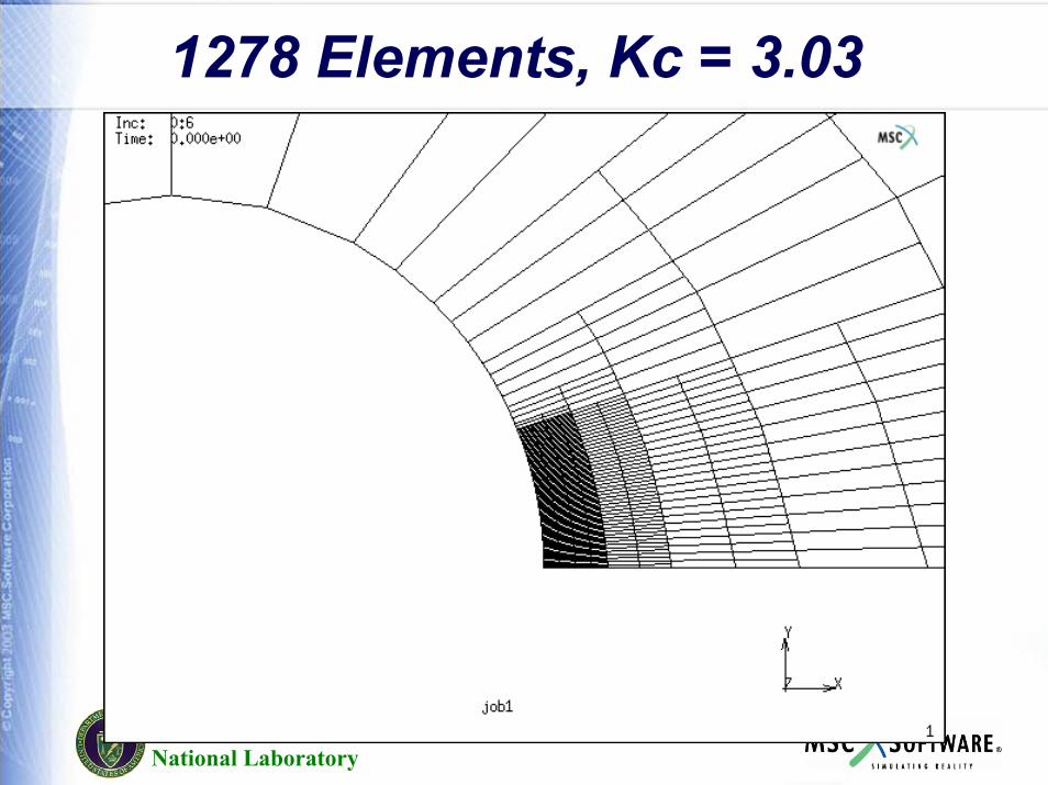
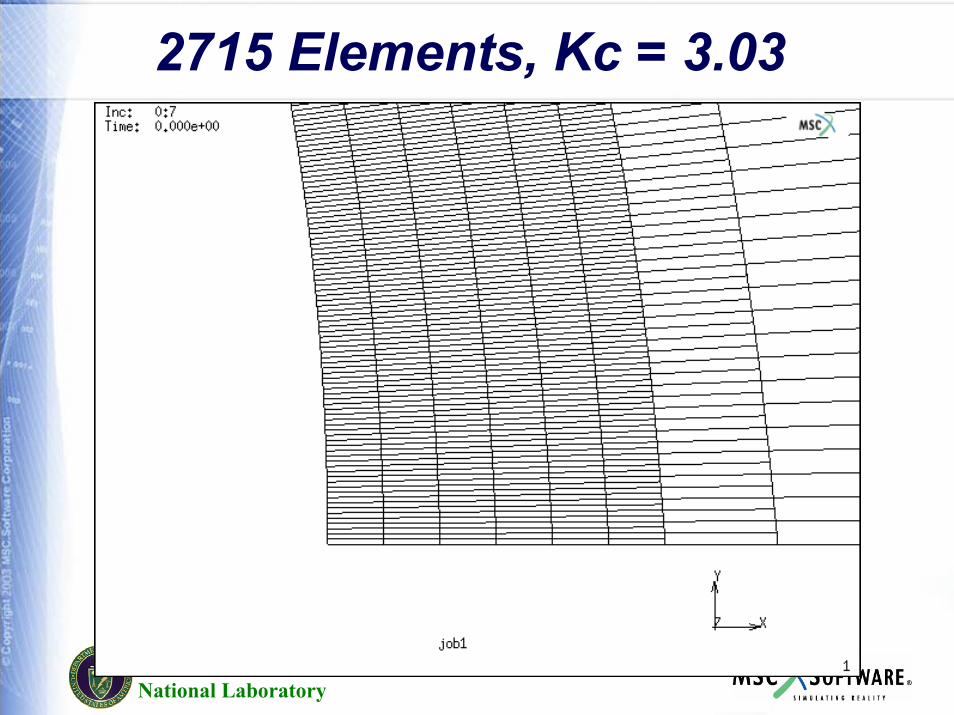
Stress Concentration – Plate with Hole
Pacific NorthwestNational Laboratory
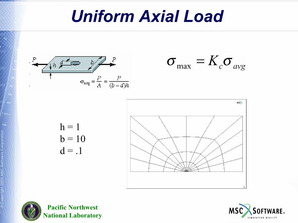
Uniform Axial Load
h = 1b = 10d = .1
Pacific NorthwestNational Laboratory
72 Elements, Kc = 1.84
Pacific NorthwestNational Laboratory
96 Elements, Kc = 2.26
Pacific NorthwestNational Laboratory
132 Elements, Kc = 2.63
Pacific NorthwestNational Laboratory
186 Elements, Kc = 2.89
Pacific NorthwestNational Laboratory
270 Elements, Kc = 3.01
Pacific NorthwestNational Laboratory
414 Elements, Kc = 3.03
Pacific NorthwestNational Laboratory
1278 Elements, Kc = 3.03
Pacific NorthwestNational Laboratory
2715 Elements, Kc = 3.03
Analysis of Composite Materials
Shells and Solids
Pacific NorthwestNational Laboratory
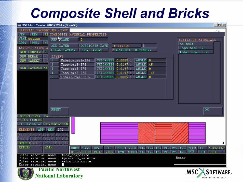
Composite Shell and Bricks
Pacific NorthwestNational Laboratory
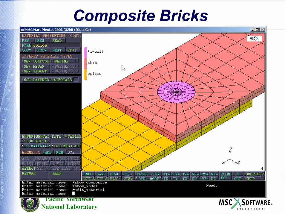
Composite Bricks
Pacific NorthwestNational Laboratory
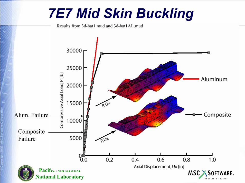
7E7 Mid Skin Buckling
Alum. Failure
CompositeFailure
Fracture Mechanics
Pacific NorthwestNational Laboratory
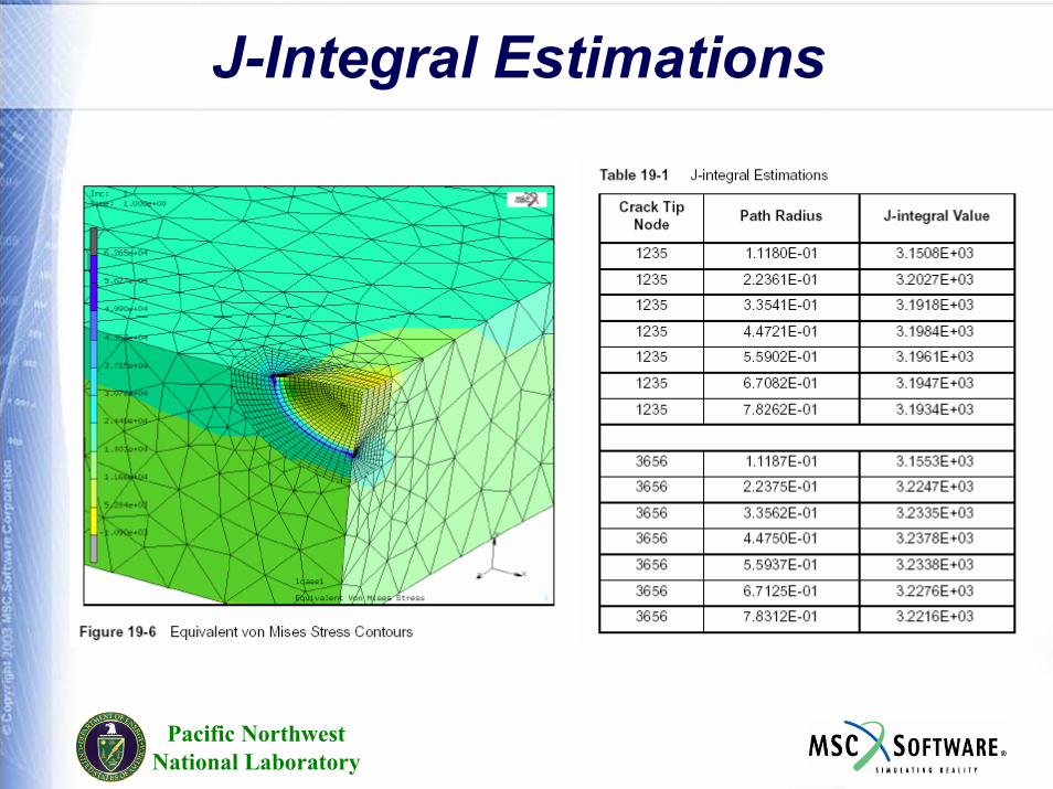
J-Integral Estimations
Heat Transfer andCoupled Thermal Stress
Pacific NorthwestNational Laboratory
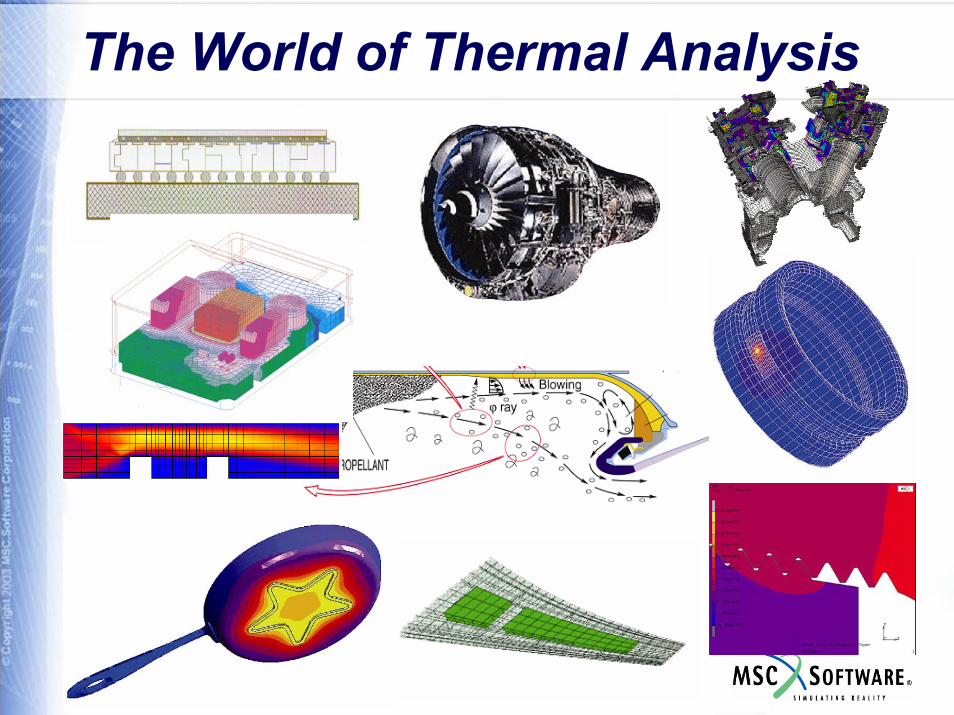
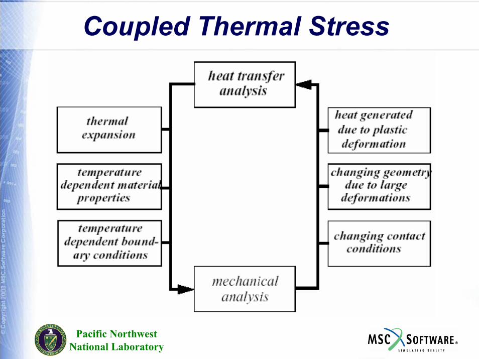
The World of Thermal Analysis
Pacific NorthwestNational Laboratory
CapabilitiesSteady State SimulationTransient Simulation Temperatures can be easily used in uncoupled thermal stress analysisCoupled Thermal-Structural AnalysisCoupled Thermal-Electric (Joule Heating) Coupled Thermal-Electric-Structural Choice of Time Step Procedures
Fixed Time StepsAdaptive Time Steps
Pacific NorthwestNational Laboratory
Capabilities1-d2-d (planar and axisymmetric solid and axisymmetric shells)3-d (solid, and shells)Heat transfer shells may have any number of layers, temperature varies either linearly or quadratically through layerNonlinear Transient Cyclic SymmetryAll heat transfer elements have comparable structural elements for thermal stress analysis or coupled analysis
Pacific NorthwestNational Laboratory
Capabilities
Isotropic , Orthotropic or Anisotropic thermal properties.
All properties may be function of temperature.
Latent heat effects included to model phase changes
Pacific NorthwestNational Laboratory
Capabilities
Point or Distributed FluxesConvective Boundary ConditionsRadiative HeatingView Factor Calculations efficiently done using Monte Carlo methodInternal Heating due to plasticity or friction in coupled structural analysis.Thermal Contact in coupled structural analysis.
Pacific NorthwestNational Laboratory
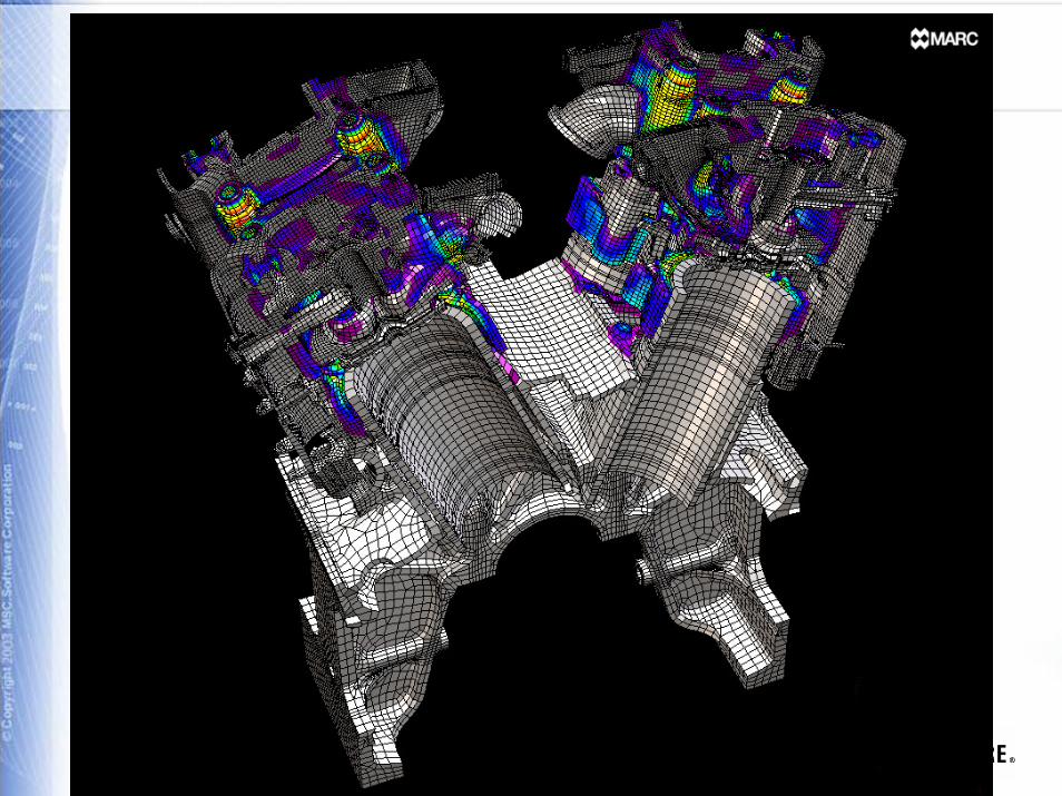
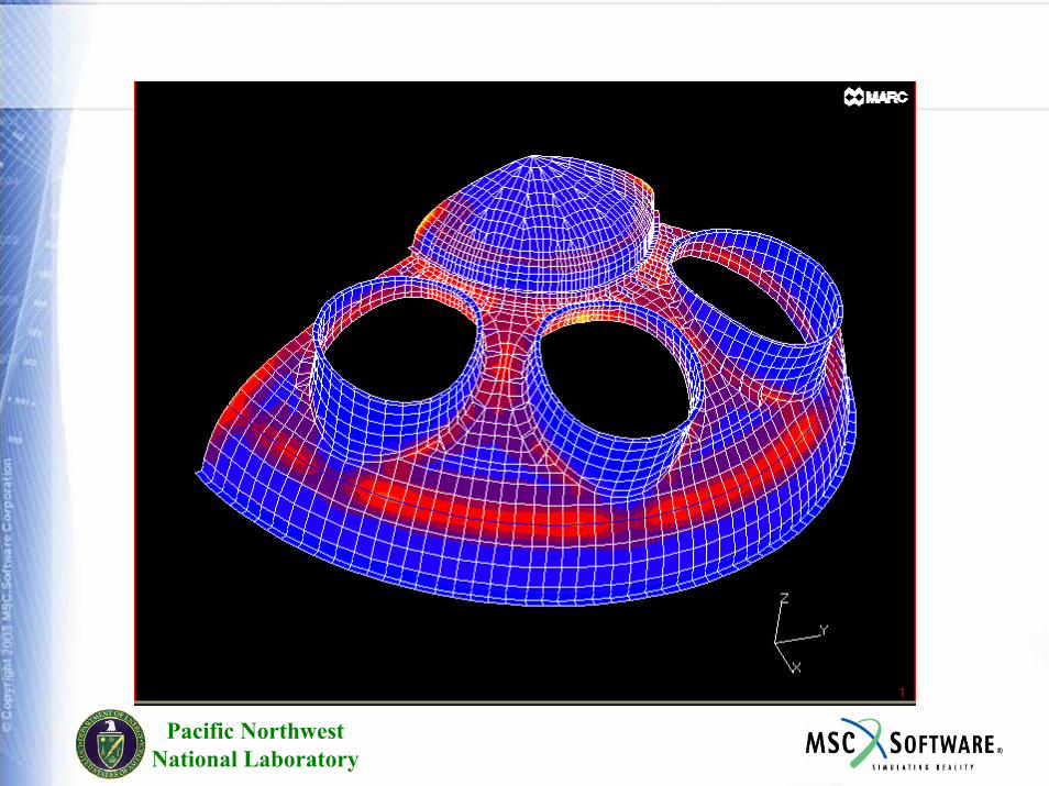
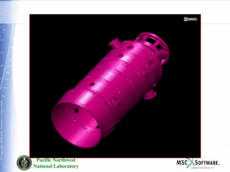
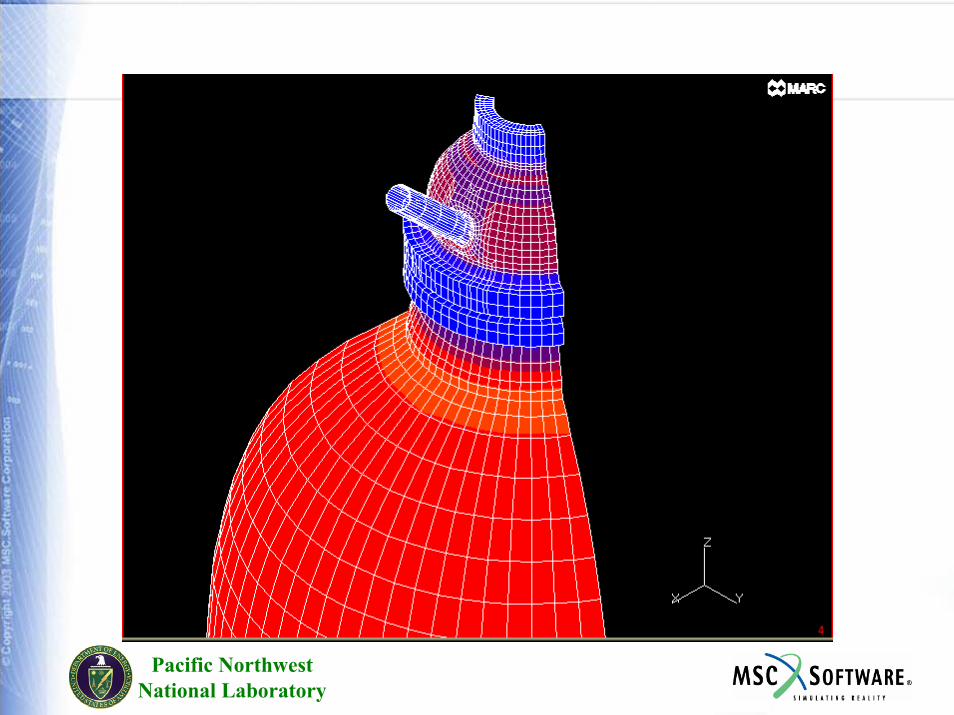
Applications
Energy IndustryEngines (Gas Turbine, Diesel, Automotive)RocketsElectronicsFire SafetyManufacturing Welding
Pacific NorthwestNational Laboratory
Pacific NorthwestNational Laboratory
Pacific NorthwestNational Laboratory
Pacific NorthwestNational Laboratory
Pacific NorthwestNational Laboratory
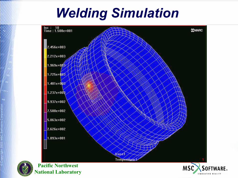
Welding Simulation
Pacific NorthwestNational Laboratory
Channel
Special Modeling techniques to represent fluid flow in channels
Special modeling techniques to model convection and radiation across small gaps.
Pacific NorthwestNational Laboratory
Computationally Efficient Solution Methods
Direct Sparse Solvers
Iterative Solvers
Parallel Processing using Domain Decomposition
Pacific NorthwestNational Laboratory
Turbine Blade Structural Analysis
Number of Domains: 4Number of Elements: 72KDegrees of Freedom: 55KScaling: 4.2X
Pacific NorthwestNational Laboratory
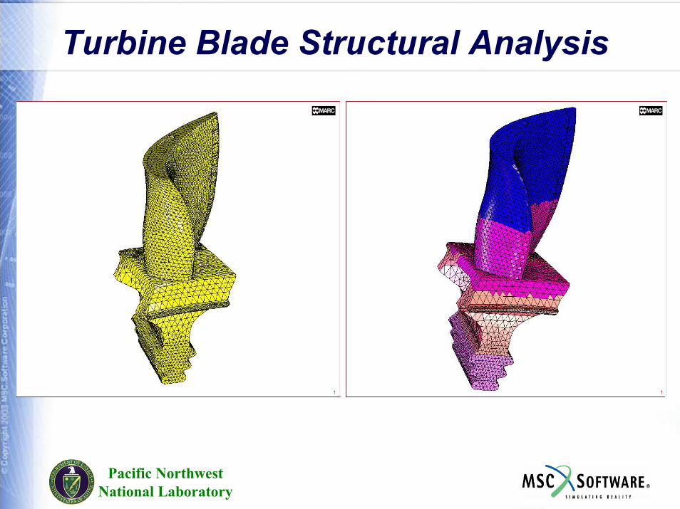
Turbine Blade Structural Analysis
Pacific NorthwestNational Laboratory
Thermal Contact
If dist < d1 then thermal conduction
If d1< dist < d2 then simplified thermal radiation
If d2 < dist then no contact
Pacific NorthwestNational Laboratory
Near Contact
ConvectionNatural convectionRadiationDistance dependent convection
Q = hcv*(T2-T1)+hnt*(T2-T1)ent +sigma*eps*(T24-T14) +
(hct – (hct-hbl)*gap/dqnear)*(T2-T1)
Pacific NorthwestNational Laboratory
Thermal Contact InputHct – contact thermal coefficientHcve – environment thermal coefficientTsink – sink temperatureHcv – near convective coefficientHnc – near natural convection coefficientBnc – exponent for natural convectionEm – emissivityHbl – lower limit of distance dependent convection coeffDqnear – distance below which near thermal behavior is applied
Pacific NorthwestNational Laboratory
Coupled Joule Heating
Weak coupling between mechanical, thermal, and electrical fieldsTypical application: high voltage electrical switchElectronic circuits
Pacific NorthwestNational Laboratory
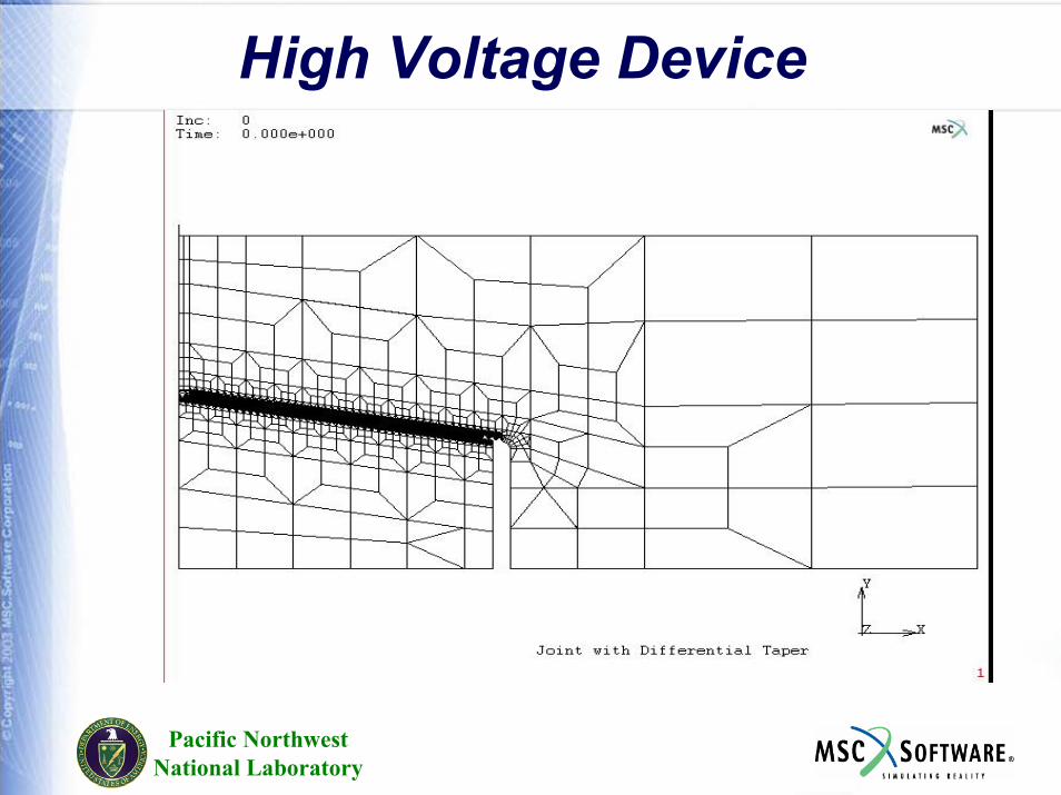
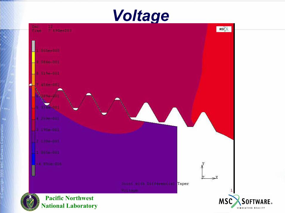
High Voltage Device
Pacific NorthwestNational Laboratory
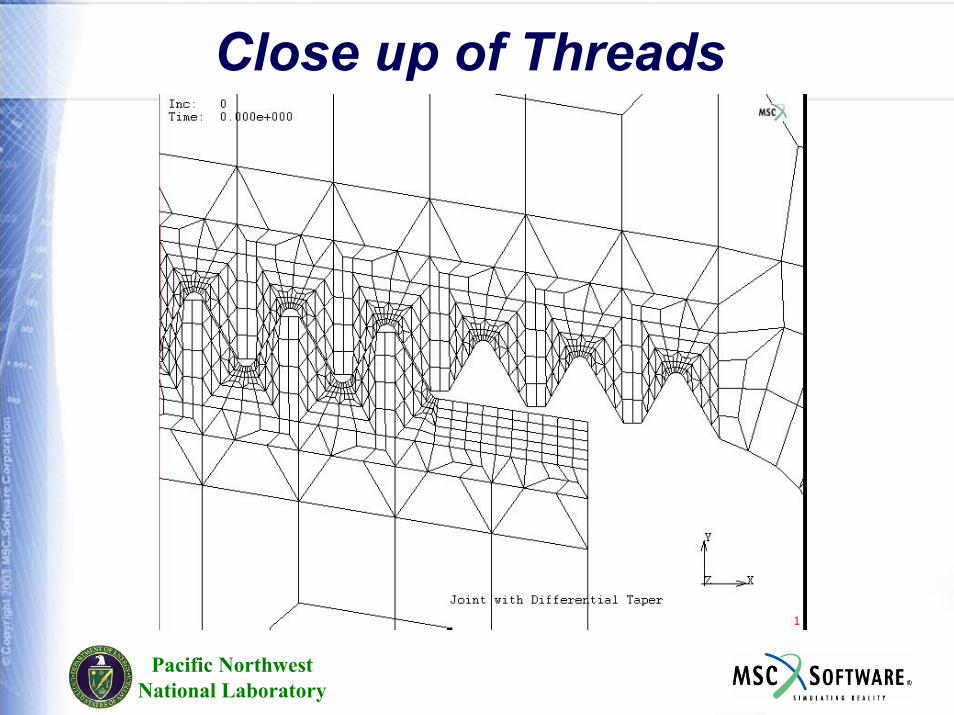
Close up of Threads
Pacific NorthwestNational Laboratory
Voltage
Pacific NorthwestNational Laboratory
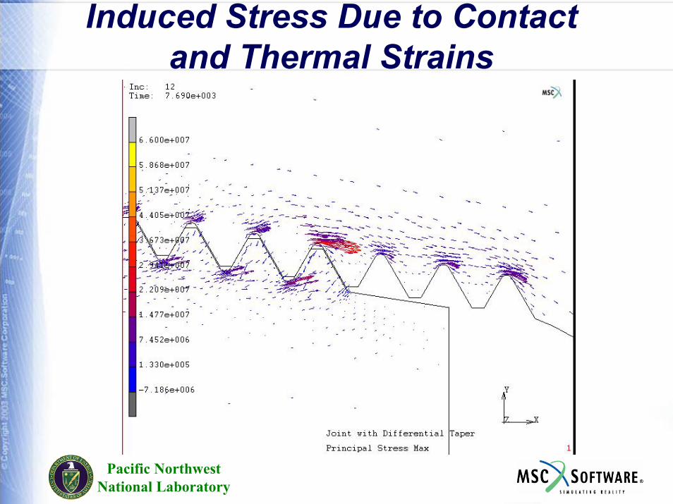
Induced Stress Due to Contact and Thermal Strains
Pacific NorthwestNational Laboratory
Fluid –Thermal Analysis
Navier Stokes Finite Element Procedure UsedTightly Coupled AnalysisIncompressible FluidLaminar FlowNewtonian or Non-Newtonian Fluid2D or 3D fluid flow with any type of elementForced or Free Convection
Pacific NorthwestNational Laboratory
Fluid-Thermal Applications
Electronic PackagingQuenchingFuel Cells
Pacific NorthwestNational Laboratory
Coupled Thermal Stress
Pacific NorthwestNational Laboratory
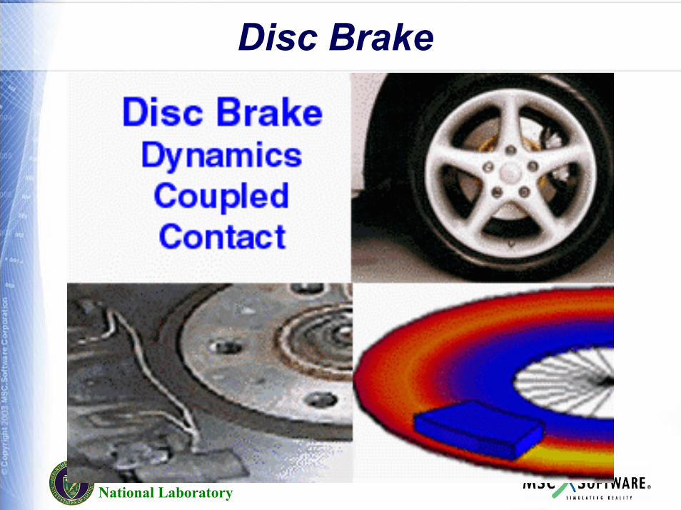
Disc Brake

Parallelization
Pacific NorthwestNational Laboratory
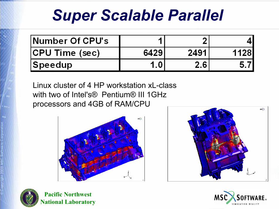
Super Scalable Parallel
Linux cluster of 4 HP workstation xL-class with two of Intel's® Pentium® III 1GHz processors and 4GB of RAM/CPU
Pacific NorthwestNational Laboratory
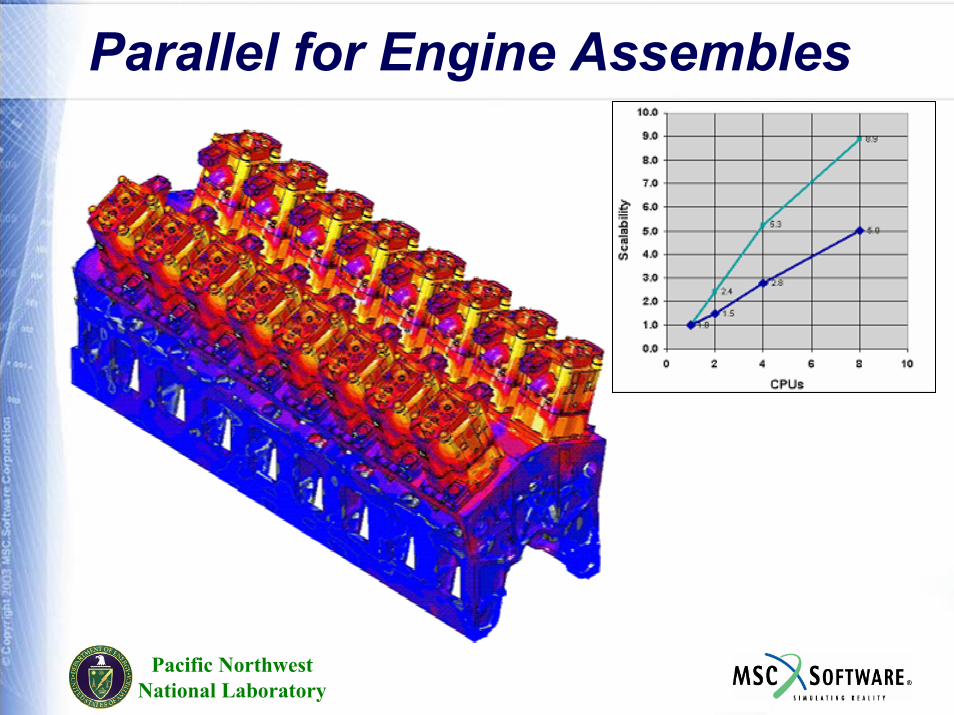
Parallel for Engine Assembles
Fluids
Pacific NorthwestNational Laboratory
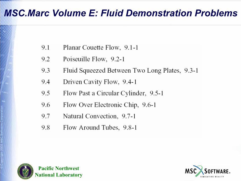
MSC.Marc Volume E: Fluid Demonstration Problems
Pacific NorthwestNational Laboratory
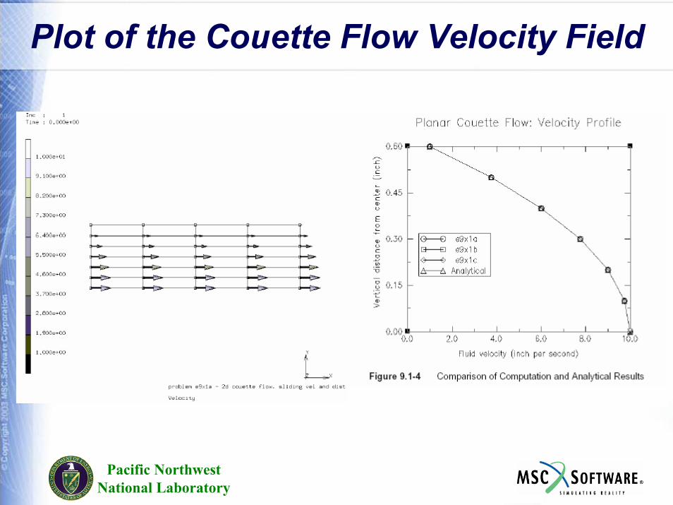
Plot of the Couette Flow Velocity Field
Pacific NorthwestNational Laboratory
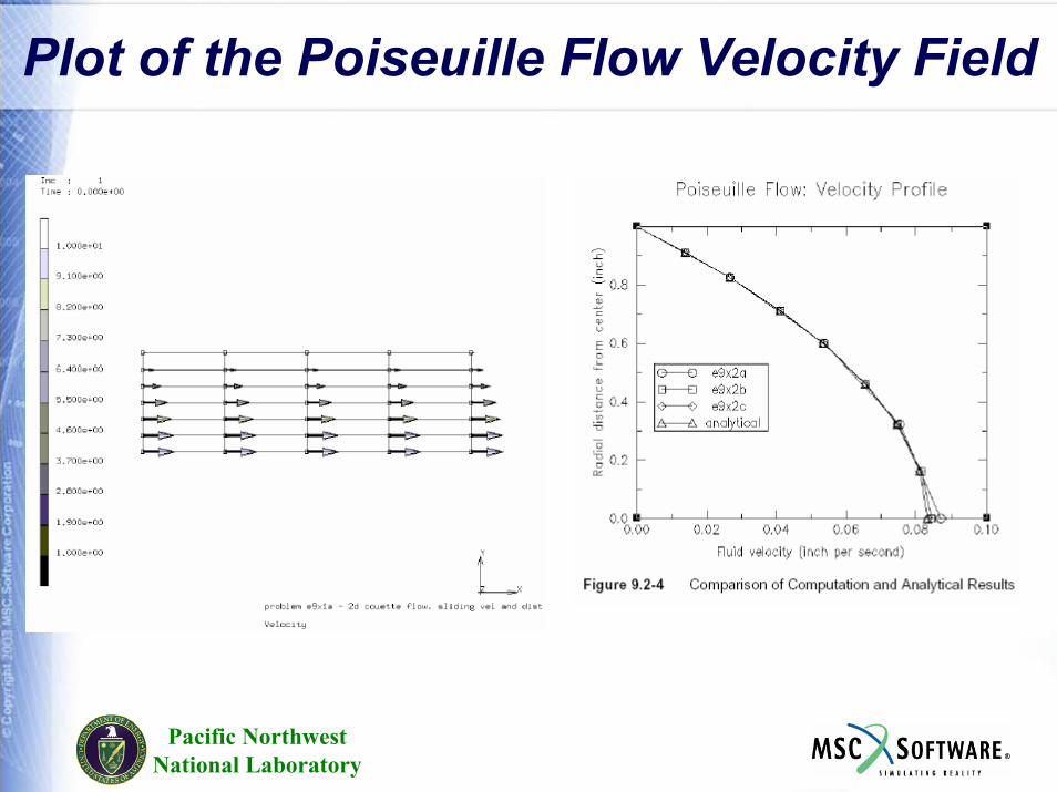
Plot of the Poiseuille Flow Velocity Field
Pacific NorthwestNational Laboratory
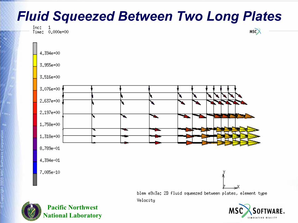
Fluid Squeezed Between Two Long Plates
Pacific NorthwestNational Laboratory
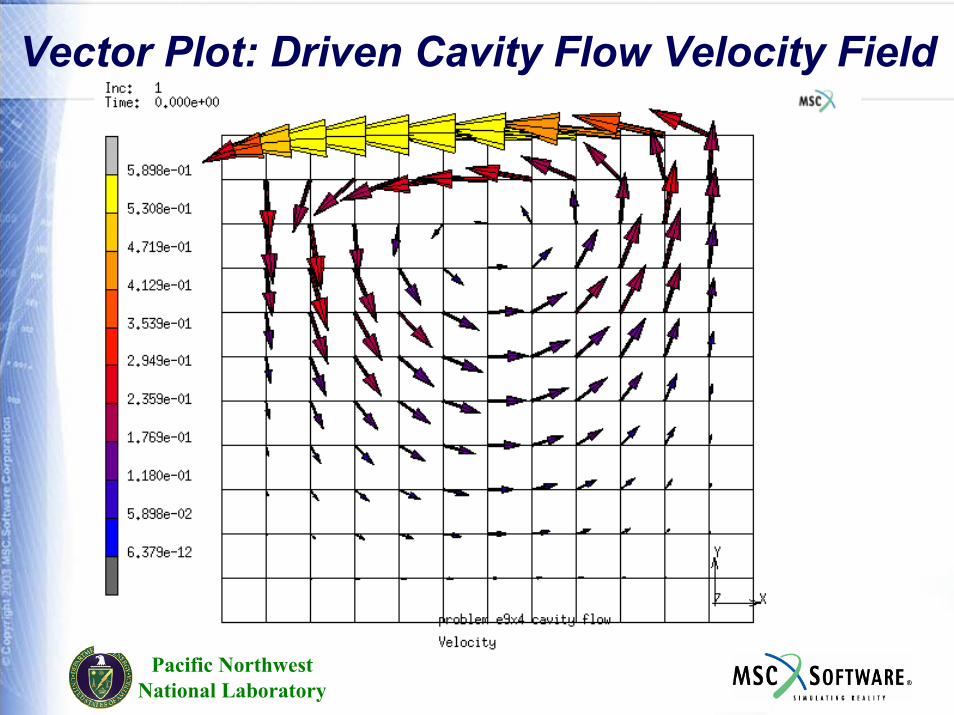
Vector Plot: Driven Cavity Flow Velocity Field
Pacific NorthwestNational Laboratory
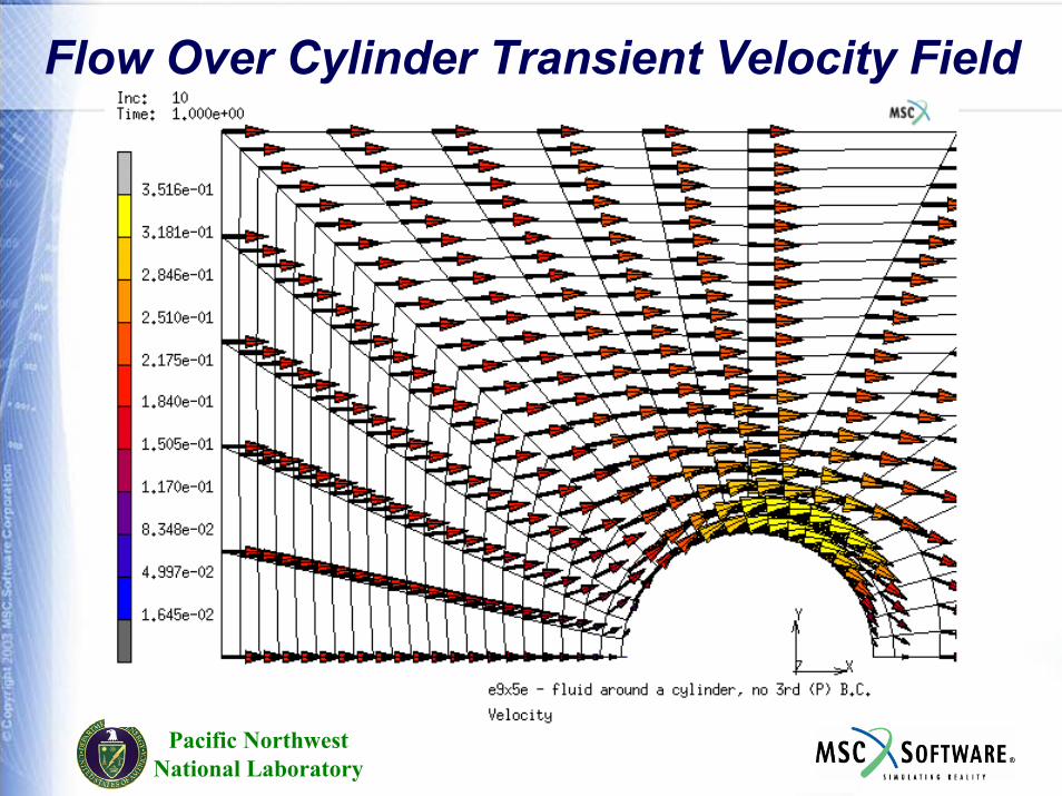
Flow Over Cylinder Transient Velocity Field
Pacific NorthwestNational Laboratory
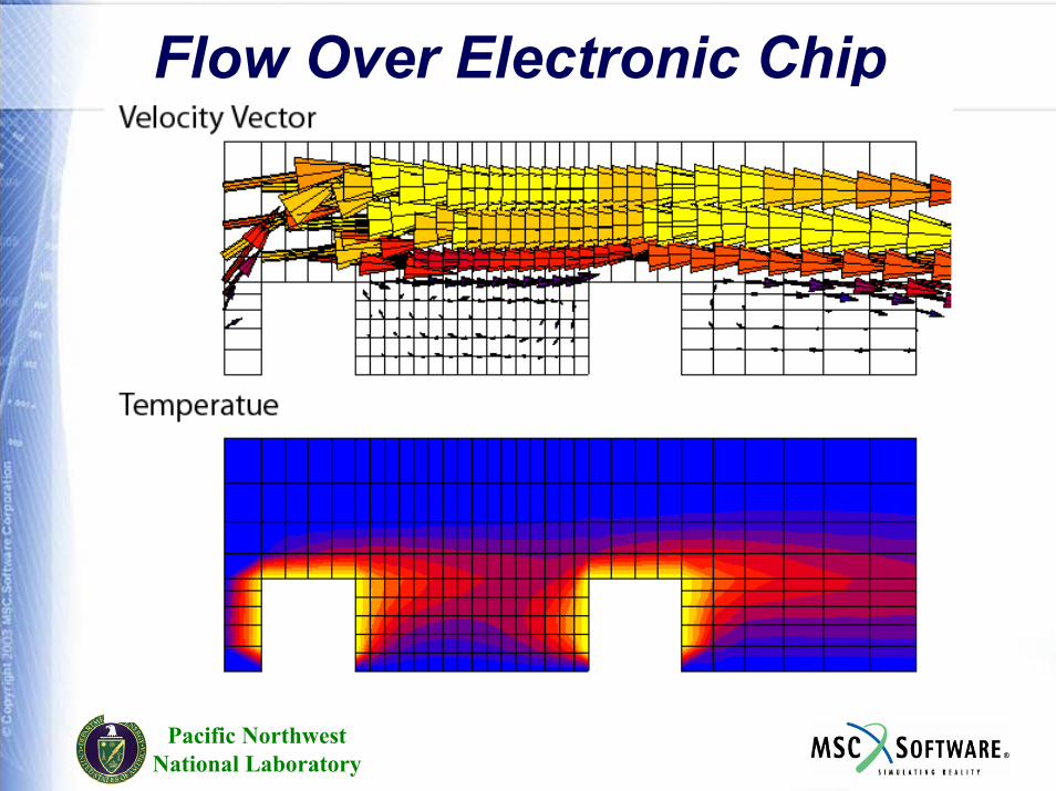
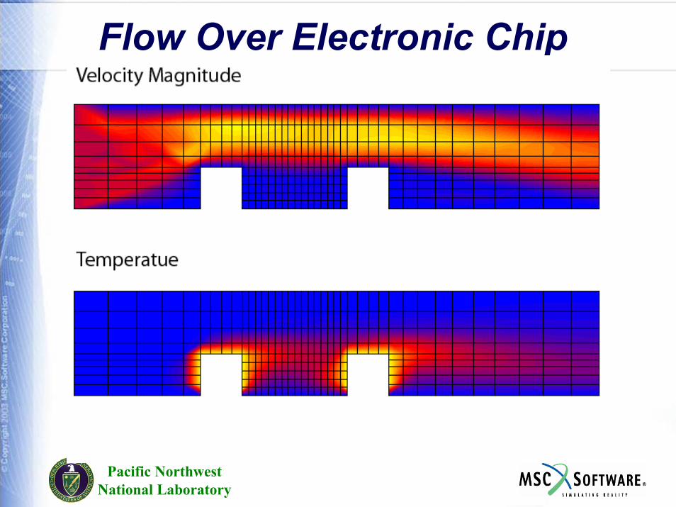
Flow Over Electronic Chip
Pacific NorthwestNational Laboratory
Flow Over Electronic Chip
User Subroutines
Pacific NorthwestNational Laboratory
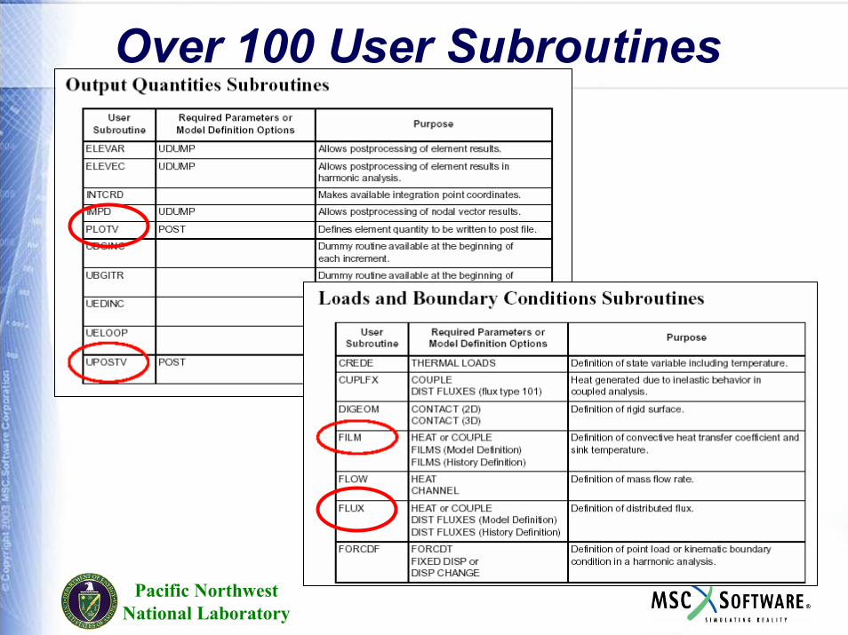
Over 100 User Subroutines
Pacific NorthwestNational Laboratory
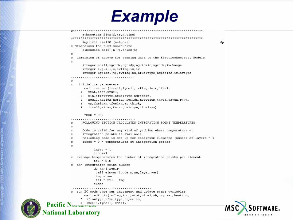
Example

Future Work
On Fuel Cells
Pacific NorthwestNational Laboratory
Proposed DevelopmentTo develop a customized graphical user interface for fuel cell stacks. To integrate an EC module currently used by PNNL into MSC.Marc to be able to analyze the thermal stresses arising as a consequence of the heat production due to chemical reaction in the fuel cell and heat transfer due to convection effects.To conduct a feasibility study of the accuracy and efficiency of MSC.Marc for simulating flow fields in a typical fuel cell stack and to use the results of this feasibility study to determine areas of possible improvement in MSC.Marc’s fluid capabilities.

PEN Fuel Cell Modeling
Pacific NorthwestNational Laboratory
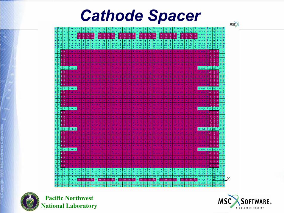
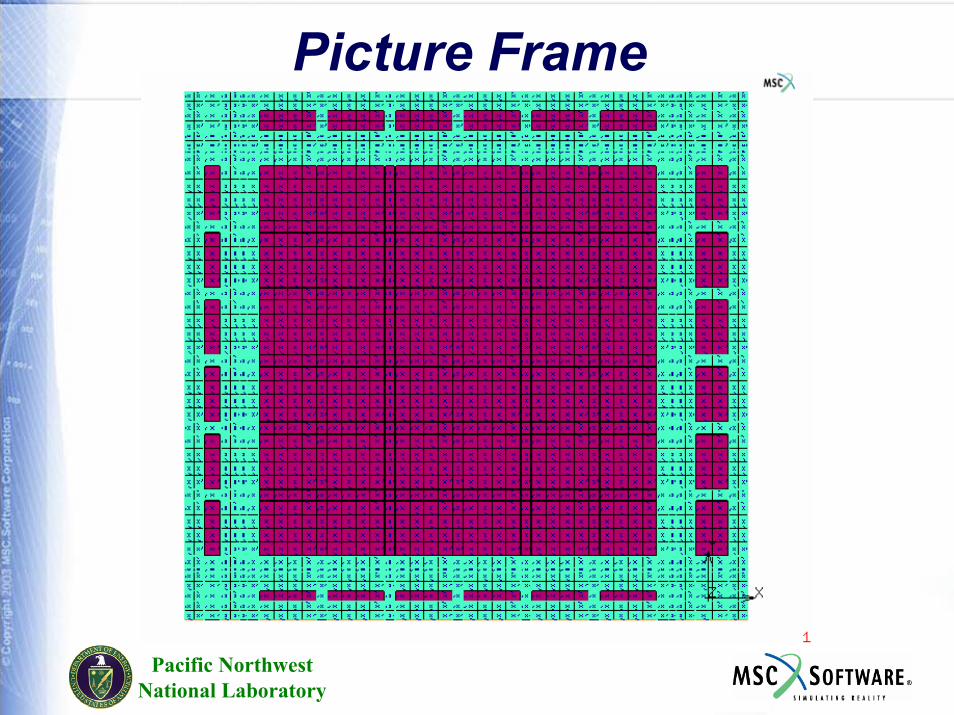
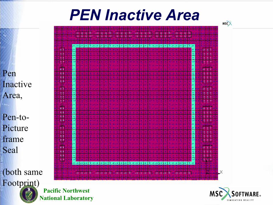
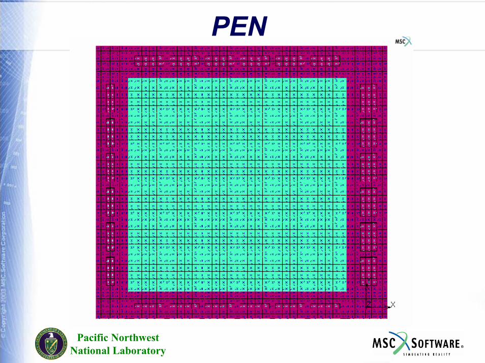
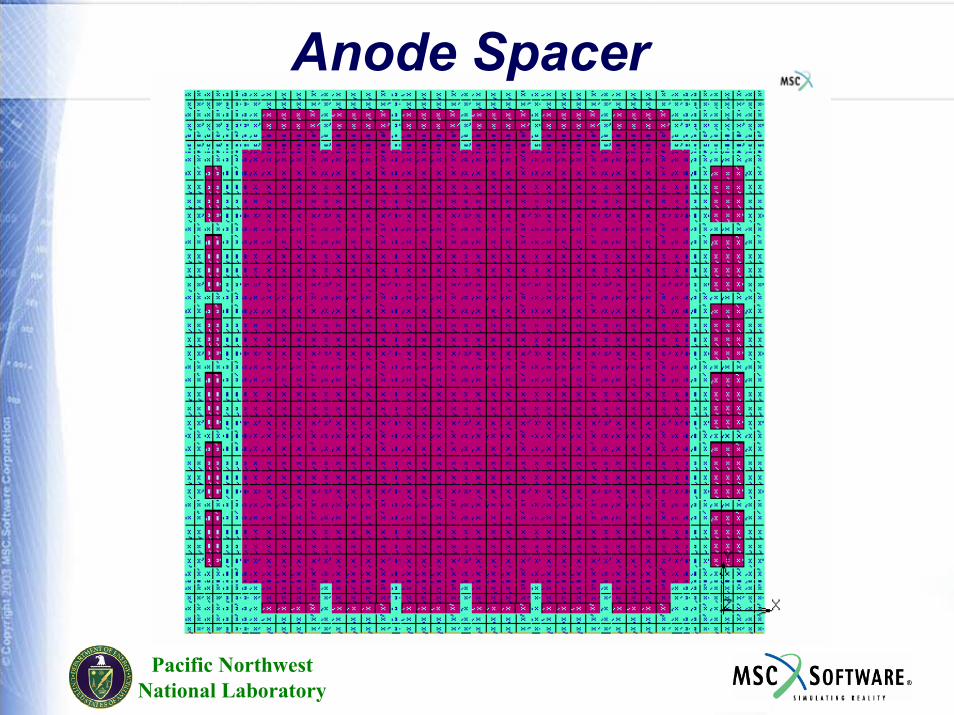
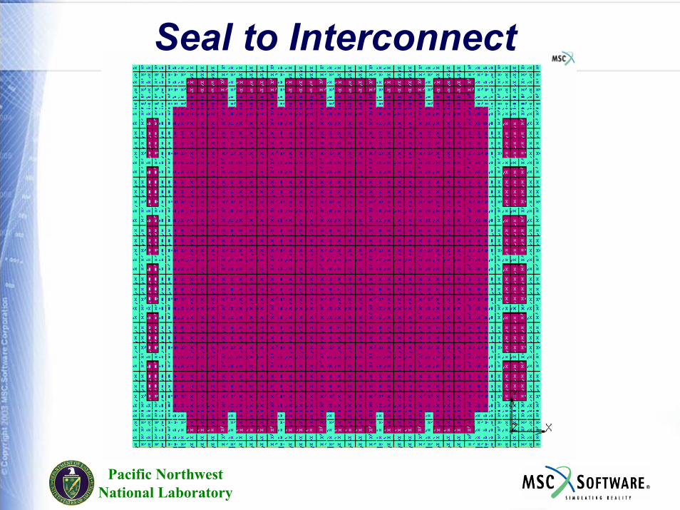
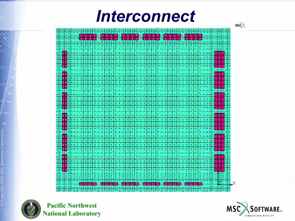
Fuel Cell Layer ConfigurationThe following slides show the layers of a typical planar fuel cell design.In the example design, the layers stack up to make up air and fuel flow channels on each side of the PEN.The PEN has 3 layers, Cathode (air-side), Electrolyte, and Anode (fuel-side). The center area (inside where the PEN seals to the picture-frame) is where the electrochemistry occurs.The following slides show “footprints” of the various layers (the selected areas show in the blue-green color).The layers are listed in the order from the interconnect (conductive layer between stacked cells), to the cathode-side layers,the PEN, anode-side layers, to the interconnect on the anode-side.The last 2 slides show the layers from bottom (cathode) and top (anode) views with the interconnect layers removed.The flow/ heat transfer/EC/stress model must have the necessary connectivity through all these layers, including through the flow channels where no mesh is shown in the last 2 slides.

Pacific NorthwestNational Laboratory
Interconnect
Pacific NorthwestNational Laboratory
Cathode Spacer
Pacific NorthwestNational Laboratory
Picture Frame
Pacific NorthwestNational Laboratory
PenInactiveArea,
Pen-to-PictureframeSeal
(both sameFootprint)
PEN Inactive Area
Pacific NorthwestNational Laboratory
PEN
Pacific NorthwestNational Laboratory
Anode Spacer
Pacific NorthwestNational Laboratory
Seal to Interconnect
Pacific NorthwestNational Laboratory
Interconnect
Pacific NorthwestNational Laboratory
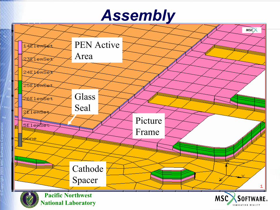
CathodeSpacer
PictureFrame
PEN ActiveArea
GlassSeal
Assembly
Pacific NorthwestNational Laboratory
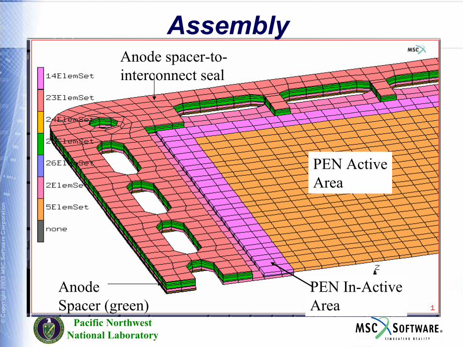
PEN ActiveArea
PEN In-ActiveArea
AnodeSpacer (green)
Anode spacer-to-interconnect seal
Assembly
Pacific NorthwestNational Laboratory
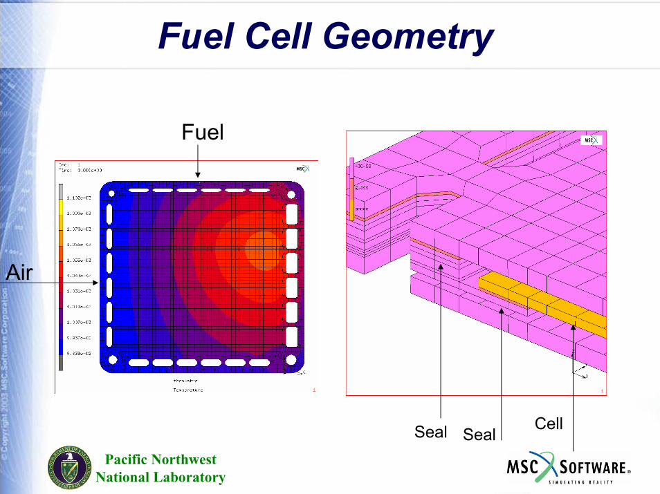
Fuel Cell Geometry
Air
Fuel
CellSeal Seal
Pacific NorthwestNational Laboratory
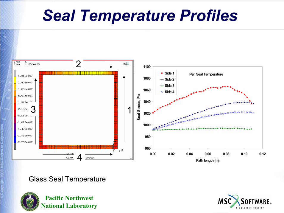
Seal Temperature Profiles
1
2
3
4
Pen Seal Temperature
960
980
1000
1020
1040
1060
1080
1100
0.00 0.02 0.04 0.06 0.08 0.10 0.12
Path length (m)
Seal
Str
ess,
Pa
Side 1Side 2Side 3Side 4
Glass Seal Temperature
Pacific NorthwestNational Laboratory
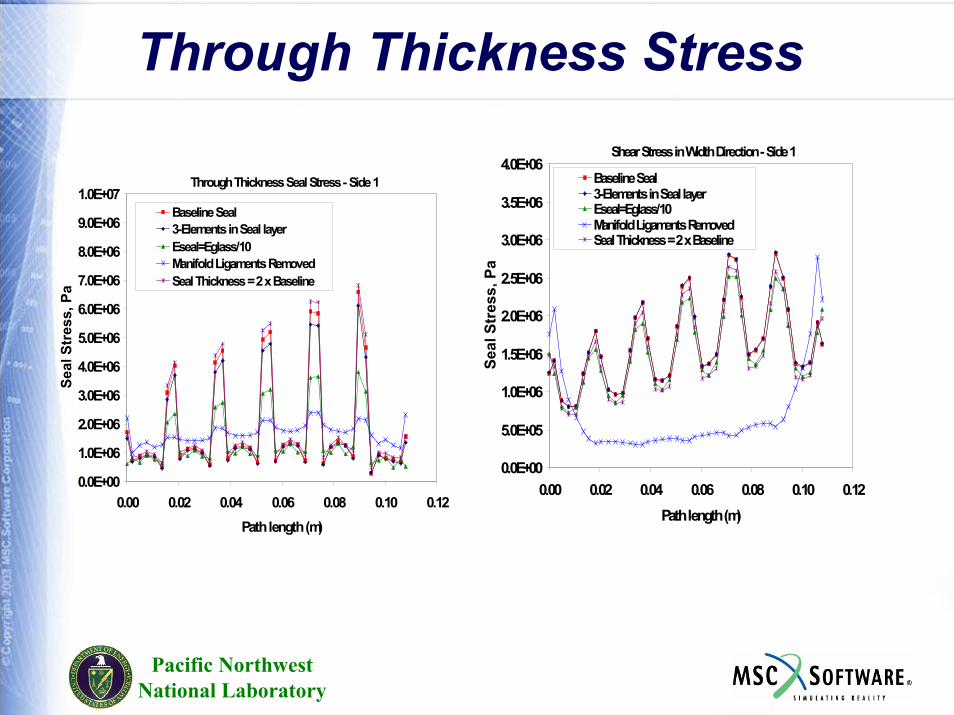
Through Thickness Stress
Through Thickness Seal Stress - Side 1
0.0E+00
1.0E+06
2.0E+06
3.0E+06
4.0E+06
5.0E+06
6.0E+06
7.0E+06
8.0E+06
9.0E+06
1.0E+07
0.00 0.02 0.04 0.06 0.08 0.10 0.12Path length (m)
Seal
Str
ess,
Pa
Baseline Seal3-Elements in Seal layerEseal=Eglass/10Manifold Ligaments RemovedSeal Thickness = 2 x Baseline
Shear Stress in Width Direction - Side 1
0.0E+00
5.0E+05
1.0E+06
1.5E+06
2.0E+06
2.5E+06
3.0E+06
3.5E+06
4.0E+06
0.00 0.02 0.04 0.06 0.08 0.10 0.12Path length (m)
Seal
Str
ess,
Pa
Baseline Seal3-Elements in Seal layerEseal=Eglass/10Manifold Ligaments RemovedSeal Thickness = 2 x Baseline
Pacific NorthwestNational Laboratory
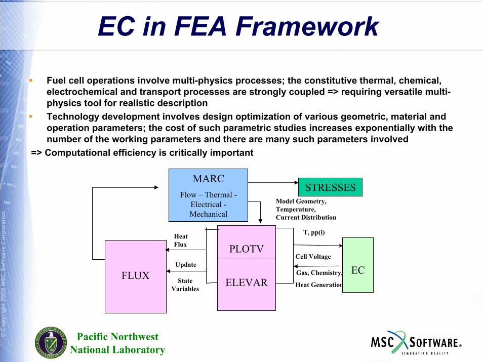
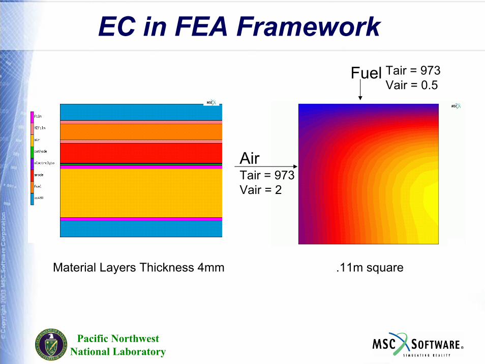
EC in FEA Framework
Fuel cell operations involve multi-physics processes; the constitutive thermal, chemical, electrochemical and transport processes are strongly coupled => requiring versatile multi-physics tool for realistic descriptionTechnology development involves design optimization of various geometric, material and operation parameters; the cost of such parametric studies increases exponentially with the number of the working parameters and there are many such parameters involved
=> Computational efficiency is critically important
MARCFlow – Thermal -
Electrical -Mechanical
STRESSES
FLUX
Heat Flux PLOTV
ELEVAREC
T, pp(i)
Cell Voltage
Gas, Chemistry,
Heat Generation
Update
State Variables
Model Geometry, Temperature, Current Distribution
Pacific NorthwestNational Laboratory
EC in FEA FrameworkFuel Tair = 973
Vair = 0.5
AirTair = 973Vair = 2
Material Layers Thickness 4mm .11m square


