65
MiniTest 1100 - 2100 Technical Manual and Operating Instructions Advancing with Technology ElektroPhysik
| Date post: | 20-Dec-2015 |
| Category: |
Documents |
| Upload: | abdulquddus |
| View: | 1,301 times |
| Download: | 163 times |

MiniTest 1100 - 2100
Technical Manual and Operating Instructions
Advancing with Technology ElektroPhysik

© 01/2003 B20-N
Technische Änderungen vorbehalten.
Subject to change without notice.
ElektroPhysik Dr. Steingroever GmbH & Co. KG
Pasteurstr. 15
50735 Köln
Deutschland
Tel.: +49 221 752040Fax.: +49 221 7520467
web: www.elektrophysik.com

ElektroPhysik E-i
Short Instructions with Key Symbols
Standard calib ra tion
One-point CALwithout foils
ZE RO
Z E R O f lash ing
n x
Z E R O s tea dy.
ZE RO
ZEROCLR
C ON TIN UE
Two-point CAL w ithZero and 1 foil
n x
Z E R O s tea dy
ZE RO CAL fo il CAL
C AL flash ing C AL steady
n x
n = Put down 1,2,3... x
= Select value or number
ZE RO
Z E R O f lash ing
E-ii ElektroPhysik
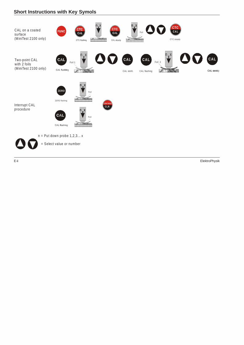
Short Instructions with Key Symols
CAL on a coa ted surface (M iniTest 2100 only)
Two-point CAL w ith 2 foils (M iniTest 2100 only)
Interrupt CALprocedure
CTC steady
n xn x
Fo il
CTCCA L
Foil 1CAL
CAL steht.
n xCAL CAL
CAL steht.
n xCAL
Foil 2CAL
CAL flash ing CAL steady
n x
n xn x
Fo ilZE RO
Z E RO f lash ing
CLRC ON T IN UE
n xn x
Fo il
n = Pu t down probe 1,2,3... x
= Select value or number

ElektroPhysik E-iii
Delete Functions
Delete the last read ing
Delete statistics(M iniTest 2100 only)
CLRCON TINU E
Delete all readings, statisticsand calibration values(Tota l Reset)
LÖ SC H
C LR
LÖ SC HCLR STATS
CLR
LÖ SC HCLR STATS
CLR
E-iv ElektroPhysik
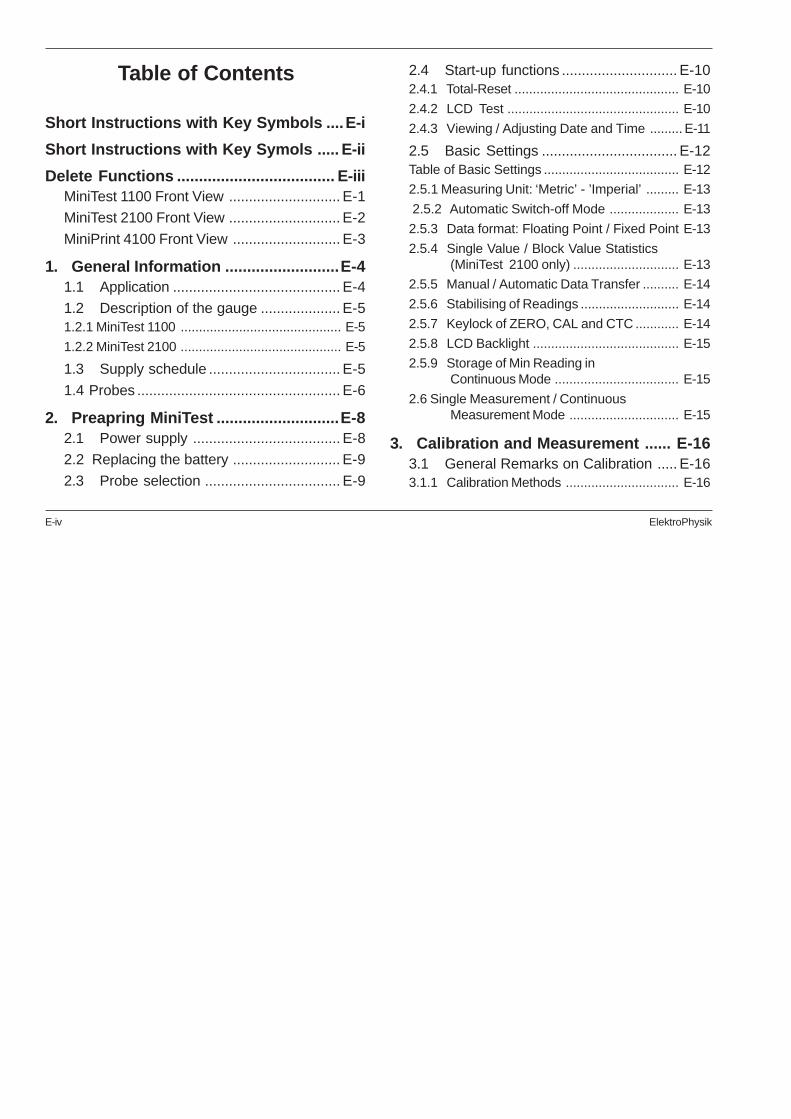
Table of Contents
Short Instructions with Key Symbols ....E-i
Short Instructions with Key Symols ..... E-ii
Delete Functions .................................... E-iiiMiniTest 1100 Front View ............................ E-1
MiniTest 2100 Front View ............................ E-2
MiniPrint 4100 Front View ........................... E-3
1. General Information ..........................E-41.1 Application .......................................... E-4
1.2 Description of the gauge .................... E-51.2.1 MiniTest 1100 ............................................ E-5
1.2.2 MiniTest 2100 ............................................ E-5
1.3 Supply schedule ................................. E-5
1.4 Probes ................................................... E-6
2. Preapring MiniTest ............................E-82.1 Power supply ..................................... E-8
2.2 Replacing the battery ........................... E-9
2.3 Probe selection .................................. E-9
2.4 Start-up functions ............................. E-102.4.1 Total-Reset ............................................. E-10
2.4.2 LCD Test ............................................... E-10
2.4.3 Viewing / Adjusting Date and Time ......... E-11
2.5 Basic Settings .................................. E-12Table of Basic Settings ..................................... E-12
2.5.1 Measuring Unit: ‘Metric’ - ’Imperial’ ......... E-13
2.5.2 Automatic Switch-off Mode ................... E-13
2.5.3 Data format: Floating Point / Fixed Point E-13
2.5.4 Single Value / Block Value Statistics(MiniTest 2100 only) ............................. E-13
2.5.5 Manual / Automatic Data Transfer .......... E-14
2.5.6 Stabilising of Readings ........................... E-14
2.5.7 Keylock of ZERO, CAL and CTC ............ E-14
2.5.8 LCD Backlight ........................................ E-15
2.5.9 Storage of Min Reading inContinuous Mode .................................. E-15
2.6 Single Measurement / ContinuousMeasurement Mode .............................. E-15
3. Calibration and Measurement ...... E-163.1 General Remarks on Calibration ..... E-163.1.1 Calibration Methods ............................... E-16

ElektroPhysik E-v
3.1.2 Storage of Calibration Values ................. E-17
3.1.3 Example of Calibration ........................... E-17
3.1.4 Influence of Substrate Thickness ........... E-18
3.1.5 High-Accuracy Calibration ...................... E-18
3.1.6 Cleaning the Measuring Point ................ E-19
3.1.7 Acoustic Signals .................................... E-19
3.1.8 Stabilisation of Calibration Values .......... E-19
3.2 Special Hints for Calibration ............. E-193.2.1 Enable Standard Calibration ................... E-19
E-19
3.2.2 One-Point Calibration without Foil(Zeroing) ................................................ E-20
3.2.3 Two-Point Calibration (ZERO with one calibration foil ............. E-21
3.2.4 Two-point Calibration with two Foils (MiniTest 2100 only) ............................ E-23
3.2.5 CTC: Calibration Through the Coating(MiniTest 2100 only) ............................. E-25
3.2.6 Dual Probes FN...................................... E-26
3.2.7 N10 and N20 Probes .............................. E-26
3.2.8 N100 Probe ............................................ E-27
3.2.9 F20 Probe .............................................. E-29
3.2.10 F50 Probe .............................................. E-30
3.2.11 Tube probes F1.6/90, F2/90,N1.6/90 and N2/90 ................................ E-31
3.2.12 Chrome Coatings on Copper .................. E-31
3.2.13 CN02 Probe ......................................... E-31
3.2.14 Shot-blasted Surfaces .......................... E-32
3.2.15 Adjusting to Basic Calibration .............. E-33
3.3 General Remarks on Measurement E-33
3.4 Using the Foot-Operated Switch ..... E-34
4. Measurement Using Statistics ...... E-344.1 Statistical Terms .............................. E-35
4.2 Entering a Series of Readings forStatistics Calculation ...................... E-36
4.3 Deleting an Erratic or False ReadingE-36
4.4 Storage Capacity Overflow .............. E-36
4.5 Display and Print-out of theStatistics of a Measuring Series ..... E-37
4.5.1 Single value statistics ............................ E-37
4.5.2 Block value statistics ............................. E-37
4.6 Print-out of all Statistical Values andReadings of a Series ofMeasurements ................................ E-38
4.6.1 Single value statistics .............................. E-38

E-vi ElektroPhysik
4.6.2 Block value statistics ............................. E-39
5. Delete Functions ............................ E-415.1 Deleting the last Reading: ................ E-41
5.2 Deleting Data Memory (Statistical and Measuring Values) .................. E-41
5.3 Deleting Calibration, Measuring andStatistical Values, Total Reset ........ E-42
6. Using the Gauge without Probe ... E-42
7. MiniPrint 4100 Data Printer ........... E-42
8. Connecting a PC ........................... E-42
9. Gauge Control via PC .................... E-43
10. Combination Interface for Foot-operated Switch, Bleeperor Lamp .......................................... E-43
11. Interface Descriptions forMiniTest and MiniPrint .................. E-43
12. Useful Accessories ........................ E-43
13. Maintenance and MaintenanceContracts ....................................... E-44
14. After-Sales Service ........................ E-44
15. Trouble Shooting ........................... E-44
16. EC Declaration of Conformity ....... E-45
17. Measuring Example ....................... E-45
18. Technical Data ................................ E-47Index ...................................................... E-54

ElektroPhysik E-1
110 µ m
FUN C
LÖ S CH
PrintPRINT
CON TINU E
CLR
M EA N
1
4
Z ERO
3
56
1021
12
13
2
19
1617
18
14
15NO N -FER RO U S
ZERO20
22
CAL
11
MiniTest 1100 Front View
1 Probe socket
2 Indicates that the gauge is currently controlled via PC. MiniTestkey-lock activated.
3 BAT: Low battery / storage battery indicator
4 Mode indicator: NON-FERROUS for measurements on non-ferrous substrates, FERROUS for measurements on steel
5 Measuring unit: Switches automatically according to probeconnected, setting and/or measuring value: µm, mm or mils,inch
6 Interface for MiniPrint, Mitutoyo Mini processor, PC etc.
7 - 9 ---
10 Arrow-keys for parameter setting (e.g. calibration values)
11 Key to switch to continuous mode
12 Delete key
13 Socket (optional) for connecting lamp our horn (to confirmmeasuring value)
14 Socket for AC adaptor
15 Mean value indicator (no statistical value)
16 4-digit LCD with floating point
17 Zero setting indicator
18 ON/OFF key
19 Key for activating upper key function
20 Key for zeroing without calibration standard
21 Key for calibrating with calibration standards
22 Battery compartment at bottom side
E-2 ElektroPhysik
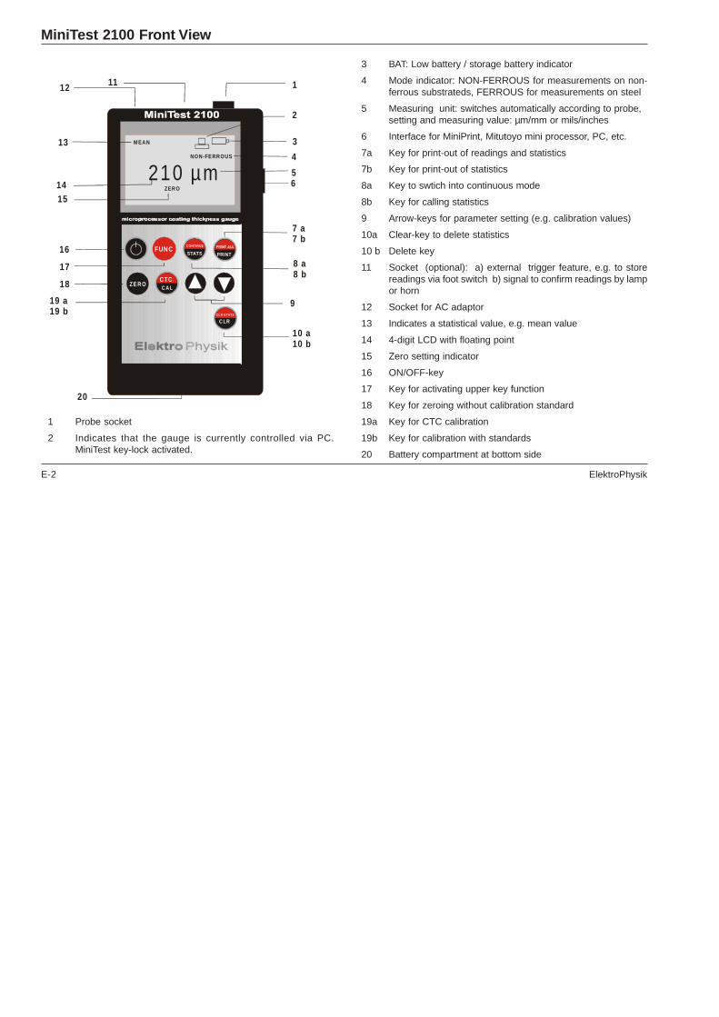
MiniTest 2100 Front View
3 BAT: Low battery / storage battery indicator
4 Mode indicator: NON-FERROUS for measurements on non-ferrous substrateds, FERROUS for measurements on steel
5 Measuring unit: switches automatically according to probe,setting and measuring value: µm/mm or mils/inches
6 Interface for MiniPrint, Mitutoyo mini processor, PC, etc.
7a Key for print-out of readings and statistics
7b Key for print-out of statistics
8a Key to swtich into continuous mode
8b Key for calling statistics
9 Arrow-keys for parameter setting (e.g. calibration values)
10a Clear-key to delete statistics
10 b Delete key
11 Socket (optional): a) external trigger feature, e.g. to storereadings via foot switch b) signal to confirm readings by lampor horn
12 Socket for AC adaptor
13 Indicates a statistical value, e.g. mean value
14 4-digit LCD with floating point
15 Zero setting indicator
16 ON/OFF-key
17 Key for activating upper key function
18 Key for zeroing without calibration standard
19a Key for CTC calibration
19b Key for calibration with standards
20 Battery compartment at bottom side
1 Probe socket
2 Indicates that the gauge is currently controlled via PC.MiniTest key-lock activated.
210 µ m
FUNC
LÖSCH
PrintPRINT
CLR STATS
C LR
CTCC A L
MEAN
1
4
ZERO
3
56
8 a8 b
10 a10 b
7 a7 b
19 a 19 b
11
2
17
1415
16
12
13NON-FERROUS
ZER O
CONTINUE
STATS
18
20
9

ElektroPhysik E-3
1 Connector pin for MiniTest
2 ON/OFF-key
3 Green LED, switch on control lamp
4 Interface
5 Socket for charger unit
6 Low battery indicator
7 Battery charge control lamp
8 Paper feed
AC CULOW C HARGE
2
4
3
18
6
7
ElektroPhysikSTATS- PROGRAM
02-Mar-02 09:41
Probe F302-Mar-02 07:35
STATISTICSN-Val 20Mean 124.6 µmSt. D 9.1%Max 150.6 µmMin 104.2 µm
MiniPrint 4100 Front View
E-4 ElektroPhysik
Foreword
The present operating instructions has been designedfor both MiniTest 1100 and MiniTest 2100. Please selectyour applicable sections from the table of contents orindex.
The last section includes short instructions along withan example measurement.
1. General InformationThe MiniTest 1100 and 2100 coating thickness gaugeswork either on the magnetic induction principle or on theeddy current principle, depending on the type of probeused. If dual probes are connected, MiniTest works onboth principles.
The gauges conform to the following industrial standards:
DIN EN ISO 2178, DIN EN ISO 2360, DIN EN ISO 2808,DIN 50982 and
ASTM B244, ASTM B499.
1.1 Application
This compact and handy gauge is designed for non-destructive, fast and precise coating thicknessmeasurement. The principal applications lie in the fieldof corrosion protection. It is ideal for manufacturers andtheir customers, for offices and specialist advisers, forpaintshops and electroplaters, for the chemical, auto-mobile, shipbuilding and aircraft industries and for lightand heavy engineering.
MiniTest gauges are suitable for laboratory, workshopand outdoor use.
When connected to the MiniPrint 4100 portable dataprinter, the gauge can document all readings andstatistical values, either immediately or for later analysis.
A large selection of probes is available to cover a widerange of applications.
F probes work on the magnetic induction principle andshould be used for non-magnetic coatings such asaluminium, chrome, copper, zinc, paint and varnish,enamel, rubber etc., on an iron or steel substrate; theyare also suitable for alloyed and hardened magnetic steel(however, they are not suitable for austenic steel).
ElektroPhysik E-5
N probes work on the eddy current principle and shouldbe used for insulating coatings e.g. paint, anodizing,ceramics, etc., on all non-ferrous metals such as Alumi-nium, copper, zinc die casting, brass etc. and onaustenitic stainless steels.
FN probes are dual probes and work both principles,magnetic induction and on the eddy current principle.One probe only is required for coating measurement bothon ferrous and non-ferrous metal substrates.
All MiniTest ‘smart’ probes are adaptable to specific tasks;i.e. they can be used on special geometries or onmaterials with special properties. Special probe data arestored within the probe to be recalled for the requiredconditions.
1.2 Description of the gauge
MiniTest can be connected to an controlled via a perso-nal computer thus making it a network capable tool inautomated work places.
Measured values and user information are shown onlarge, easy-to-read LC display. A display back lightensures easy reading of screen data, in dark conditions.
1.2.1 MiniTest 1100
Basic model, easy to use, without data memory andstatistics. Can be connected to MiniPrint 4100 data printerfor immediate print-out of all readings.
1.2.2 MiniTest 2100
This model includes a data memory and statistics. Up to10,000 reading can be stored and statistically evaluated.
Statistics include 6 values. If connected to the MiniPrint4100 data printer, all single readings along with statisticscan be printed out immediately during measurement orat a later date.
1.3 Supply schedule
Gauge with alkaline battery, plastics carrying case,screw driver, operating instructions (German/English).
Optional accessories:
- probes
- zero plate and calibration standards according toprobe selection
E-6 ElektroPhysik
- MiniPrint 4100, portable data printer. Can beconnected laterally to the MiniTest gauge withoutusing a cable
- Belt-case set - two cases of different sizes forgauge and accessories
- Dust protection case
- Twin case for gauge and printer
- ‘MSave’ program disc for data acquisition via PC
- ‘MSoft41’ program disc for WINDOWS 3.1x® orWINDOWS 9x® to process MiniTest measuringand statistical values, (MiniTest 2100 only)
- connecting cable (serial), 9 or 25 pole connectionfor PC
- connecting cable for Mitutoyo mini processor
- high precision measuring stand for measuring onsmall parts
- mains adaptor 230V AC/12V DC
- mains adaptor 110V AC/12V DC
- accumulator battery and charger, 230V AC or110V AC
1.4 Probes
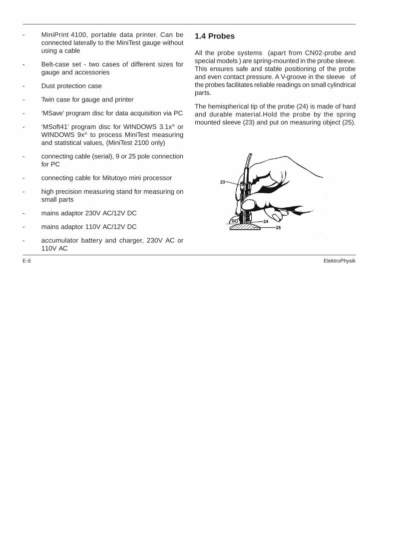
All the probe systems (apart from CN02-probe andspecial models ) are spring-mounted in the probe sleeve.This ensures safe and stable positioning of the probeand even contact pressure. A V-groove in the sleeve ofthe probes facilitates reliable readings on small cylindricalparts.
The hemispherical tip of the probe (24) is made of hardand durable material.Hold the probe by the springmounted sleeve (23) and put on measuring object (25).

ElektroPhysik E-7
All probes listed in the following tables can be connectedto the MiniTest 1100 and MiniTest 2100 gauges.
The probes are identified by a type number (e.g. FN 1.06080-0402) and the colour on the protective sleeve (blackfor F probes, red for N probes and green for FN probes).Please quote the identity number when orderingreplacement probes.
Probes for measuring on steel substrates
Type Nr.Measuringrange metric
Measuringrange imperial
F05 0...500 µm 0...20 mils
F1.6 0...1600 µm 0...60 mils
F1.6/90tube probe
0...1600 µm 0...60 mils
F1.6Ppowder probe
0...1600 µm 0...60 mils
F2/90tube probe
0...2000 µm 0...80 mils
F3 0...3000 µm 0...120 mils
F10 0...10 mm 0...400 mils
F20 0...20 mm 0...800 mils
F50 0...50 mm 0...2 inches

E-8 ElektroPhysik
Dual probes for steel and non ferrous substratesProbes for non ferrous substrates
2. Preapring MiniTest
2.1 Power supply
- 1 x 9 Volt alkaline battery or
- 1 x 9 Volt accumulator battery or
- mains adapter
Type Nr.Measuringrange metric
Measuringrange imperial
FN 1.6 0...1600 µm 0...60 mils
FN 1.6 Ppowder probe
0...1600 µm 0...60 mils
FN 1.6/90tube probe
0...1600 µm 0...60 mils
FN2/90tube probe
0...2000 µm 0...80 mils
Type Nr.Measuringrange metric
Measuringrange imperial
N.08Cr 0...80 µm 0...3 mils
N02 0...200 µm 0...8 mils
N1.6 0...1600 µm 0...60 mils
N1.6/90tube probe
0...1600 µm 0...60 mils
N2/90tube probe
0...2000 µm 0...80 mils
N10 0...10 mm 0...400 mils
N20 0...20 mm 0...800 mils
N100 0...100 mm 0...4 inches
CN 02Cu-coatings oninsulating substrates
10...200 µm 0.4...8 mils

ElektroPhysik E-9
For checking the battery’s state of charge please pressON-key:
No LC display:
Battery or accumulator missing or battery charge toolow to illuminate display.
Flashing BAT display, gauge switches off after about onesecond:
Replace battery immediately.
BAT flashes durign measurement:
The battery is running low and should be replaced beforethe gauge is switched on next time. If not, the LC displaywill show the permanent BAT warning and the gaugewill switch itself off after about a second.
Note that the gauge will not make faulty measurementseven if the voltage is very low.
2.2 Replacing the battery
1. Place the gauge upside down on a suitablesurface.
2. Remove the screws from the battery compartmentwith a crosstip screwdriver.
3. Raise the lid of the compartment.
4. Remove battery.
5. Insert new battery.
6. Close the lid and fasten with screws.
Caution:
Make sure the positive and negative poles arecorrectly positioned. If not, all data saved to memorywill be lost.
An interval of more than 10 seconds between removingthe old battery and inserting the new one will also resultin the loss of data (readings, calibration values, time anddate (MiniTest 2100 only).
Battery disposal: Do not discard used batteries in yourregular trash. Please observe your local instructions forbattery disposal.
2.3 Probe selection
Select a probe according to your application, connect itto the MiniTest gauge and screw in place.
E-10 ElektroPhysik
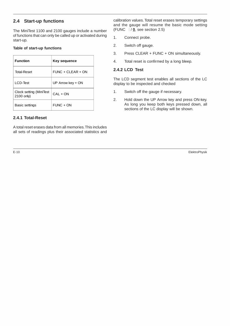
2.4 Start-up functions
The MiniTest 1100 and 2100 gauges include a numberof functions that can only be called up or activated duringstart-up.
Table of start-up functions
2.4.1 Total-Reset
A total reset erases data from all memories. This includesall sets of readings plus their associated statistics and
calibration values. Total reset erases temporary settingsand the gauge will resume the basic mode setting(FUNC : / 0, see section 2.5)
1. Connect probe.
2. Switch off gauge.
3. Press CLEAR + FUNC + ON simultaneously.
4. Total reset is confirmed by a long bleep.
2.4.2 LCD Test
The LCD segment test enables all sections of the LCdisplay to be inspected and checked
1. Switch off the gauge if necessary.
2. Hold down the UP Arrow key and press ON-key.As long you keep both keys pressed down, allsections of the LC display will be shown.
Function Key sequence
Total-Reset FUNC + CLEAR + ON
LCD-Test UP Arrow key + ON
Clock setting (MiniTest2100 only)
CAL + ON
Basic settings FUNC + ON

ElektroPhysik E-11
2.4.3 Viewing / Adjusting Date and Time
The gauge has a quartz-controlled timer which relaysinformation to the MiniPrint 4100. The current date andtime appear automatically on each print out of statistics.
To view and if necessary adjust the time and date:
1. Switch off the MiniTest gauge.
2. Hold down the CAL key and press ON. Keep bothkeys depressed until you hear the bleep. If anFN1.6 or FN2 probe is attached, press one ofthe arrow keys.
3. ‘TIME’ flashes with a preset year, e.g. <2Y>.
4. Use arrow keys to set the required year. PressCAL to confirm.
5. A month appears, e.g. <3M>. Use Arrow-keys toadjust to the required month. Press CAL to confirm.
6. A day of the month appears, e.g. <3d>. Use Arrow-keys to ajust to the required day. Press CAL toconfirm.
7. The hour now appears, e.g. <3h>, erscheint. UseArrow-keys to adjust to the requird hour. PressCAL to confirm.
8. The minute now appear, e.g. <3m>. Use Arrow-keys to adjust to the required minute.
9. To save the new date and time , press CAL again.The gauge will return automatically to measuringmode.
Note:
When you view the time and date, please remember thatthe clock stops for as long as it is on display. If the timerdoes not need adjusting, keep pressing CLEAR until thegauge returns to measuring mode.
E-12 ElektroPhysik
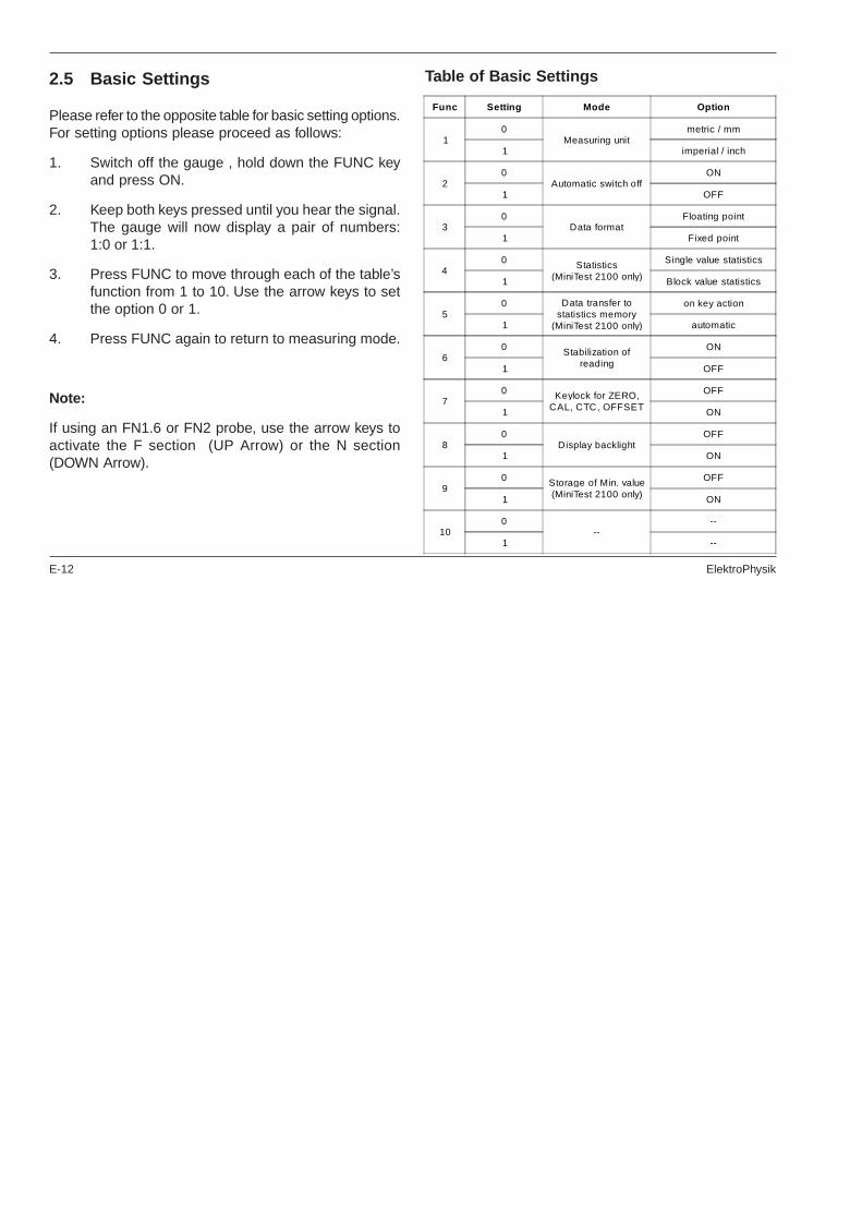
2.5 Basic Settings
Please refer to the opposite table for basic setting options.For setting options please proceed as follows:
1. Switch off the gauge , hold down the FUNC keyand press ON.
2. Keep both keys pressed until you hear the signal.The gauge will now display a pair of numbers:1:0 or 1:1.
3. Press FUNC to move through each of the table’sfunction from 1 to 10. Use the arrow keys to setthe option 0 or 1.
4. Press FUNC again to return to measuring mode.
Note:
If using an FN1.6 or FN2 probe, use the arrow keys toactivate the F section (UP Arrow) or the N section(DOWN Arrow).
Table of Basic Settings
Func Setting Mode Option
10
Measuring unitmetric / mm
1 imperial / inch
20
Automatic switch offON
1 OFF
30
Data formatFloating point
1 Fixed point
40 Statistics
(MiniTest 2100 only)
Single value statistics
1 Block value statistics
50 Data transfer to
statistics memory(MiniTest 2100 only)
on key action
1 automatic
60 Stabilization of
reading
ON
1 OFF
70 Keylock for ZERO,
CAL, CTC, OFFSET
OFF
1 ON
80
Display backlightOFF
1 ON
90 Storage of Min. value
(MiniTest 2100 only)
OFF
1 ON
100
----
1 --
ElektroPhysik E-13
2.5.1 Measuring Unit: ‘Metric’ - ’Imperial’
To switch from metric units (µm, mm, cm) to Imperials(mils, inch) or vice versa, proceed as follows:
1. Switch off gauge.
2. Hold down the FUNC key and press ON.
3. Keep both keys depressed until you hear thebleep. The gauge will now display a pair ofnumbers: 1: 0/1.
4. Use the arrow keys to adjust to the requiredmeasuring unit. 0 = metric, 1 = Imperial.
5. Press FUNC 10 times. The gauge will now returnto the measuring mode. The series of measure-ments can be continued with the new measuringunit. Previous readings in the series will beconverted to the new unit automatically (MiniTest2100 only).
2.5.2 Automatic Switch-off Mode
The gauge is programmed to switch itself off after about90 seconds of inactivity. This can hinder operations incertain circumstances. In this case the operator should
disable the automatic switch-off to operate in thecontinuous mode.
Please refer to the table of basic setting in section 2.5and use FUNC and Arrow-keys to make your setting.
2.5.3 Data format: Floating Point / Fixed Point
The standard data format of readings transferred via thecombination interface uses the floating point data format.For data loggers etc. this default setting can be changedto fixed point format.
In the fixed point format, all metric readings in micronswill be displayed with one digit after the decimal point. InImperial units, readings in mils will be displayed with twodigits after the decimal point.
To switch between fixed and floating point options, pleaserefer to the table of gauge settings in section 2.5. Adjustto the required mode using FUNC and Arrow keys.
2.5.4 Single Value / Block Value Statistics(MiniTest 2100 only)
The statistical values can be calculated on the basis ofeither individual values or blocks of values before beingtransferred to a printer or PC.

E-14 ElektroPhysik
Block value statistics are calculated from a block of meanvalues. The number of readings assigned to each blockcan be altered via a PC. Default = 5 readings.
To select the single-value or block-value option, pleaserefer to the table of gauge settings on section 2.5. Selectan option with the FUNC and arrow keys as described.
2.5.5 Manual / Automatic Data Transfer
The continuous mode allows automatic transfer ofreadings to statistics memory (only MiniTest 2100) or toa printer or PC (setting <1>). If only selected readingsare to be logged to memory, choose manualmeasurement mode (setting <0>) and enter the readingseither via the keyboard (UP Arrow-key) or by a foot-operated switch (optional extra). (See also section 2.5.9)
In automatic mode readings can be entered at a rate ofapprox. 5 per second.
To switch between automatic and manual mode, pleaserefer to the table of gauge settings in section 2.5. Selectoption with the FUNC and arrow keys as described.
2.5.6 Stabilising of Readings
In the standard gauge setting, readings are not displayed,stored into the statistics memory (MiniTest 2100 only) ortransferred to a printer or PC until the signal stabiliseswithin a given range (data filter).
In continuous measuring mode, however, this stabilisingprocedure can be disabled, e.g. for easier acquisition ofminimum and maximum readings. (See also sections4.2.8 and 4.2.14).
To disable the stabilising procedure, please refer to thetable of gauge settings in section 2.5. Select option withthe FUNC and Arrow keys as described.
2.5.7 KEYLOCK of ZERO, CAL and CTC
An accidental recalibration can be prevented by usingthe KEYLOCK function. .
To activate the KEYLOCK function of ZERO, CAL (andCTC with MiniTest 2100) please refer to the table ofgauge settings in section 2.5. Select option with theFUNC and arrow keys as described.

ElektroPhysik E-15
2.5.8 LCD Backlight
If you enable the backlight function, the display lights upfor about 2 secs after a reading has been taken. Pleaseremember that using the lamp requires extra current.
To activate the display light please refer to the table ofgauge settings in section 2.5. Select option with theFUNC and Arrow keys as described.
2.5.9 Storage of Min Reading in ContinuousMode
This function allows to determine the Min reading withina continuous measuring procedure. When measuring,the actual readings are currently updated. the currentmeasuring value is displayed. After lifting the probe fromthe surface, the Min reading (minimum value of ameasuring series) is displayed for about 5 seconds. WithMiniTest 2100, during this time, the Min reading can betransferred to the statistics via the UP arrow key or via afoot-operated switch (optional extra).
If within these 5 seconds you will not take another readingor after the Min reading has been stored to the statisticsmemory, it will disappear from display. If fur thermeasurements are taken within these 5 seconds, theexisting Min reading remains is saved and shortly
appears on display. This procedure allows to view theMin reading value for a short time while taking acontinuous measurement.
The Min reading mode is set by FUNC- and Arrow-keyas described in 2.5 and in the table of basic settings.
2.6 Single Measurement / ContinuousMeasurement Mode
It can sometimes be of advantage (measurement insidetubes) if the probe does not need to be raised betweeneach measurement so that there is a running display ofreadings.Please adjust to the continuous mode asfollows:
1. Switch on gauge.
2. Press FUNC, then CONTINUE. A short bleepconfirms the change of mode.
3. A flashing measuring unit (µm, mm, cm) indicatedsthat the continuous mode has been enabled.Readings beyond the measuring range will beindicated by 4 strokes (- - - -). In continuous mode,readings are not accompanied by a bleep andthe display lamp is disabled.
E-16 ElektroPhysik
4. To log readings to the statistics memory(MiniTest2100 only) or to print-out readings on aprinter, or to transfer readings to a PC via theinterface, press the UP Arrow key or push the foot-operated switch (optional extra).
5. For continuous input of all readings, follow theprocedure described in section 2.5.5. Readingstaken in this mode will automatically be enteredinto the statistics program as long as sufficientmemory is available.
6. Return to standard mode (i.e. single measurementmode) either by repeating steps 1 and 2 or byswitching the MiniTest off and on again. (SwitchingOFF and ON again does not apply to probes F20,F50 and N100.
3. Calibration and Measurement
3.1 General Remarks on Calibration
3.1.1 Calibration Methods
MiniTest 1100 can be calibrated according to methods1-3 and MiniTest 2100 according to methods 1-5:
1. Standard calibration: recommended formeasurement on even surfaces and if themeasuring object has the same material, size andcurvature as the ElektroPhysik zero plate .
2. One-point calibration (zeroing without using acalibration foil): recommended if measuring errorsup to ± (3% of reading* plus the constant error ofprobe) are permitted. (Example for constant pro-be error: F.1.6: 1 µm).
3. Two-point calibration (zeroing and calibratingusing a calibration foil): recommended if readignsto be expected will be close to the calibration valueand if the permitted error of probe will bemax.±(1%...3% of reading* (according to probe)plus constant probe error)
* referring to the supplied calibration standardsunder laboratory conditions.
4. Two-point calibration (using a set of twocalibration foils):
a) Recommended for measurements on roughsurfaces.
b) exact measurements are required on smoothsurfaces if the thickness to be expected liesbetween that of the two calibration foils

ElektroPhysik E-17
5. Calibration through the coating (CTC):Calibration using a calibration foil. Recommendedif the test sample is coated and no uncoatedsample is available for comparison. This methodis suitable for the following probes: F05, F1.6, F3and FN1.6 (ferrous par t only), F1.6/90, F2/90, F10, F20 and F50.
Hinweis:
In this manual, the term calibration foil applies to allcalibration standards, including those usually notdescribed as ‘foil’: e.g. those of 2mm, 5mm and 10mmthickness.
3.1.2 Storage of Calibration Values
If the gauge is calibrated for a particular purpose, thecalibration values will be stored in memory untilchanged.(See also section 3.1.8 Stabilisation ofcalibration values).
If a calibration is to be altered for a certain probe, simplycarry out a new calibration. This automatically deletesthe previous calibration values and saves the new onesfor immediate use.
Note:
The calibration procedure should be restarted from thebeginning if
· an incorrect reading is taken
· an incorrect command is entered
- the gauge has switched off
3.1.3 Example of Calibration
Calibration is the most important requirement for accuratemeasurement. The more closely the calibration samplematches the product sample, the more accurate thecalibration, and therefore the reading, will be.
Example:
If a product is to be measured on a steel cylinder, qualityST37 (mild steel), ø 6 mm, the calibration of the uncoatedsample must take place on a steel cylinder of similarquality with the same diameter.
E-18 ElektroPhysik
The calibration sample must correspond to the productsample in the following ways:
· curvature radius
· substrate material properties
· substrate thickness
· size of measuring area
· The point at which the calibration is made on thecalibration sample must always be identical withthe point of measurement on the product itself,especially in the case of corners and edges ofsmall components. The precision stand will proveinvaluable here.
For more details please refer to the technical data.
3.1.4 Influence of Substrate Thickness
In case of steel substrates, as long as the substrate isthicker than the range of probe, it is sufficient to use thestandard calibration. The minium measuring areas asspecified in the technical data should also be taken intoaccount.
In the case of non-magnetic metals, it is sufficient if thesubstrate is 50 microns thick and strong enough not togive way under the pressure of the probe tip. A thin layerof aluminium foil can be suitable, if stuck on a hard base.
The enclosed steel and aluminium zero plates are fortest purposes only and are not generally recommendedfor calibration.
Exceptions:
The zero plates may be used for calibration if the productsample has a smooth, even surface (not shot-blasted)and if it has the same thickness as the zeroplate.
3.1.5 High-Accuracy Calibration
To achieve high-accuracy readings, it is advisable to logcalibration values (both zero values and calibration foilvalues) several times in succession. In this way the gaugewill automatically establish a mean calibration value. Formore details see sections 3.2.2-3.2.9 on calibration. Thismethod is an obvious advantage when calibrating onuneven, e.g. shot-blasted, surfaces.
ElektroPhysik E-19
3.1.6 Cleaning the Measuring Point
Before calibration the measuring point, and the probetip must be free from grease, oil, scraps of metal, etc.The slightest impurity will affect measurement and distortreadings
3.1.7 Acoustic Signals
Whether the probe is being used for calibration or formeasurement, it must be held in place and not lifted untilthe bleep sounds
3.1.8 Stabilisation of Calibration Values
The gauge is temperature and drift compensated. Forthat reason it is not necessary to recalibrate inchangeable external conditions (see Technical Data).
3.2 Special Hints for Calibration
For calibration according to sections 3.2.2 to 3.2.13please proceed as follows:
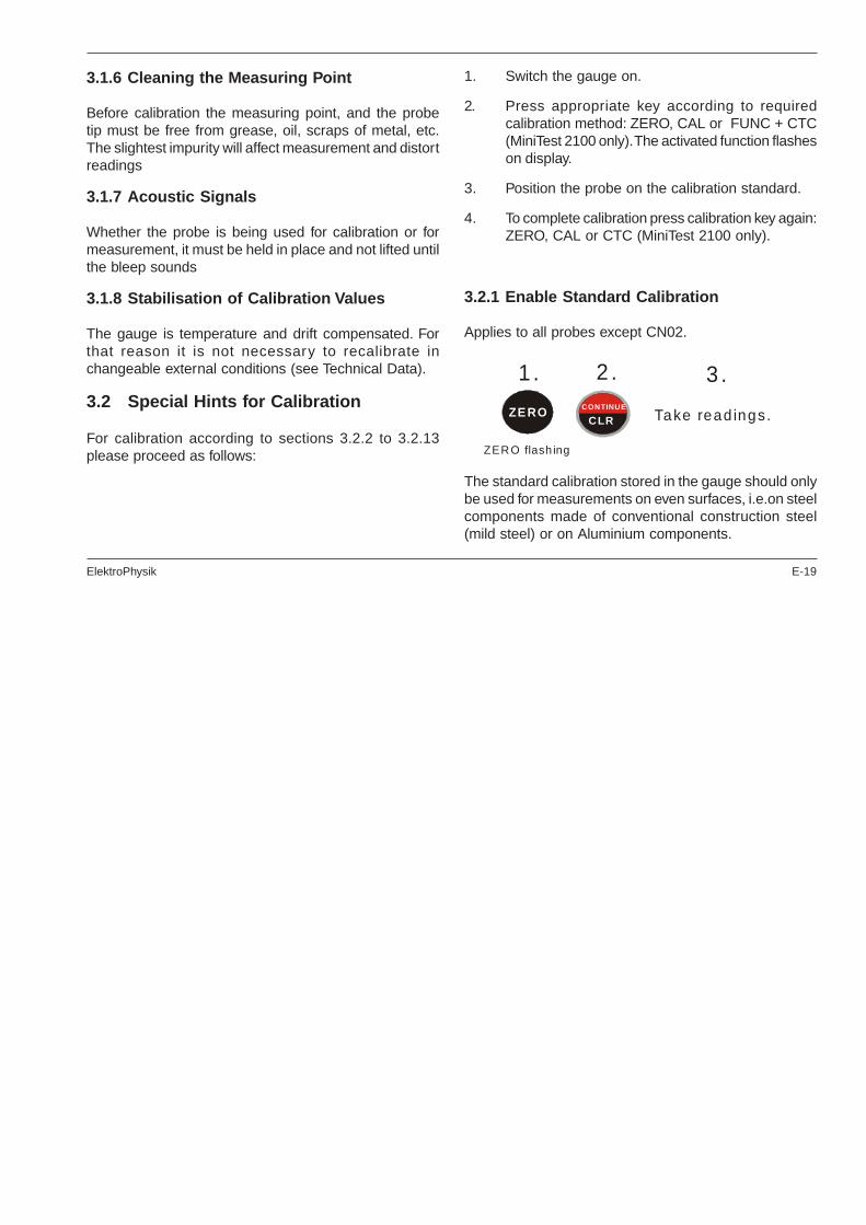
1. Switch the gauge on.
2. Press appropriate key according to requiredcalibration method: ZERO, CAL or FUNC + CTC(MiniTest 2100 only). The activated function flasheson display.
3. Position the probe on the calibration standard.
4. To complete calibration press calibration key again:ZERO, CAL or CTC (MiniTest 2100 only).
3.2.1 Enable Standard Calibration
Applies to all probes except CN02.
The standard calibration stored in the gauge should onlybe used for measurements on even surfaces, i.e.on steelcomponents made of conventional construction steel(mild steel) or on Aluminium components.
ZEROCLR
CONTINUE
1 .
ZER O flash ing
2 .
Take read ings.
3 .

E-20 ElektroPhysik
Note:
It is important to record a sufficient number of exact zeroreadings on an uncoated sample. If not, one-point or two-point calibration should be used.
3.2.2 One-Point Calibration without Foil(Zeroing)
1. Press ZERO to initialise ZERO calibration. Thedisplay will show ZERO (flashing) and MEAN(steady). MEAN indicates that the mean value ofthe readings will be shown on the display.
2. Place the probe on uncoated sample (zero coatingthickness) and raise it after the bleep. Repeat thisprocedure several times. The display alwaysshows the mean value of the previous readings.
3. Press ZERO to complete Zero calibration. ‘ZERO’appears on display.
4. Now take readings by placing the probe on theobject to be measured and raise the probe afterthe bleep. The reading is shown on display.
Deleting ZERO Calibration:
It may be necessary to delete the ZERO calibration if,for example, an incorrect zero value is entered. In thiscase:
a) press ZERO then CLEAR to delete the zerocalibration and any existing CAL calibration.
Note:
This will reactivate the default standard calibration foruse on even surfaces.
b) or restart ZERO calibration by repeating steps 1to 3 above. This automatically deletes the oldcalibration and saves the new calibration.
Note:
ZERO calibration deletes any existing CAL calibration.
ZERO
ZE R O flashing
n x
ZE R O steady
ZERO

ElektroPhysik E-21
3.2.3 Two-Point Calibration (ZERO with onecalibration foil
Applicable to all probes (except CN02).
This method is recommended for high precisionmeasurements and measurements on small parts andhardened and low-alloy steels
1. Press ZERO to initialise ZERO calibration. Thedisplay will show ZERO (flashing) and MEAN(steady). MEAN indicates that the mean value ofthe readings will be shown on the display.
2. Place the probe on uncoated sample (zero coatingthickness) and raise it after the bleep. Repeat thisprocedure several times. The display alwaysshows the mean value of the previous readings.
3. Press ZERO to complete Zero calibration. ‘ZERO’appears on display.
4. Press CAL to initialise foil calibration. CAL flashesand MEAN appears (steady). MEAN indicates thatthe mean value of the readings will be shown onthe display.
5. Lay the calibration foil on an uncoated sample,apply the probe and raise it after the bleep.Thethickness of the foil should be roughly equivalentto the estimated coating thickness. Apply the pro-be to the test sample several times. The displayalways shows the mean value of the previousreadings. To discontinue calibration, press CLEAR.
6. Use Arrow key to adjust the required foil thickness.
ZER O
ZERO flashing
n x
ZERO steady
ZER O
CAL Foil CAL
CAL flashing CAL steady
4. 5. 6. 7.
n x
E-22 ElektroPhysik
7. Press CAL. CAL will appear on the display(steady).
8. Now take readings by placing the probe on thecoating and raise it after the bleep.
It may be necessary to delete CAL calibration, e.g. afterentry of a faulty calibration value:
a) Press CAL key followed by CLEAR key. CALcalibration and any existing ZERO calibration willbe deleted.
Note:
This will reactivate the default standard calibration foruse on even surfaces.
b) Restart CAL calibration by repeating steps 4 to 7above. This automatically overwrites the old calibrationand saves the new values.
Note:
Even while a series of measurements is being taken, foilcalibration can be carried out as often as necessary. Theold calibration will be overwritten; the ZERO calibrationremains in memory.
Special remark:
When using F10, F20 or F50 probes for measuring onmetal coatings, it is essential to carry out two-pointcalibration. The calibration standards must be of the samemetal as the actual coating. Under certain circumstances,this may also apply to Fprobes with a low measuringrange.
ElektroPhysik E-23
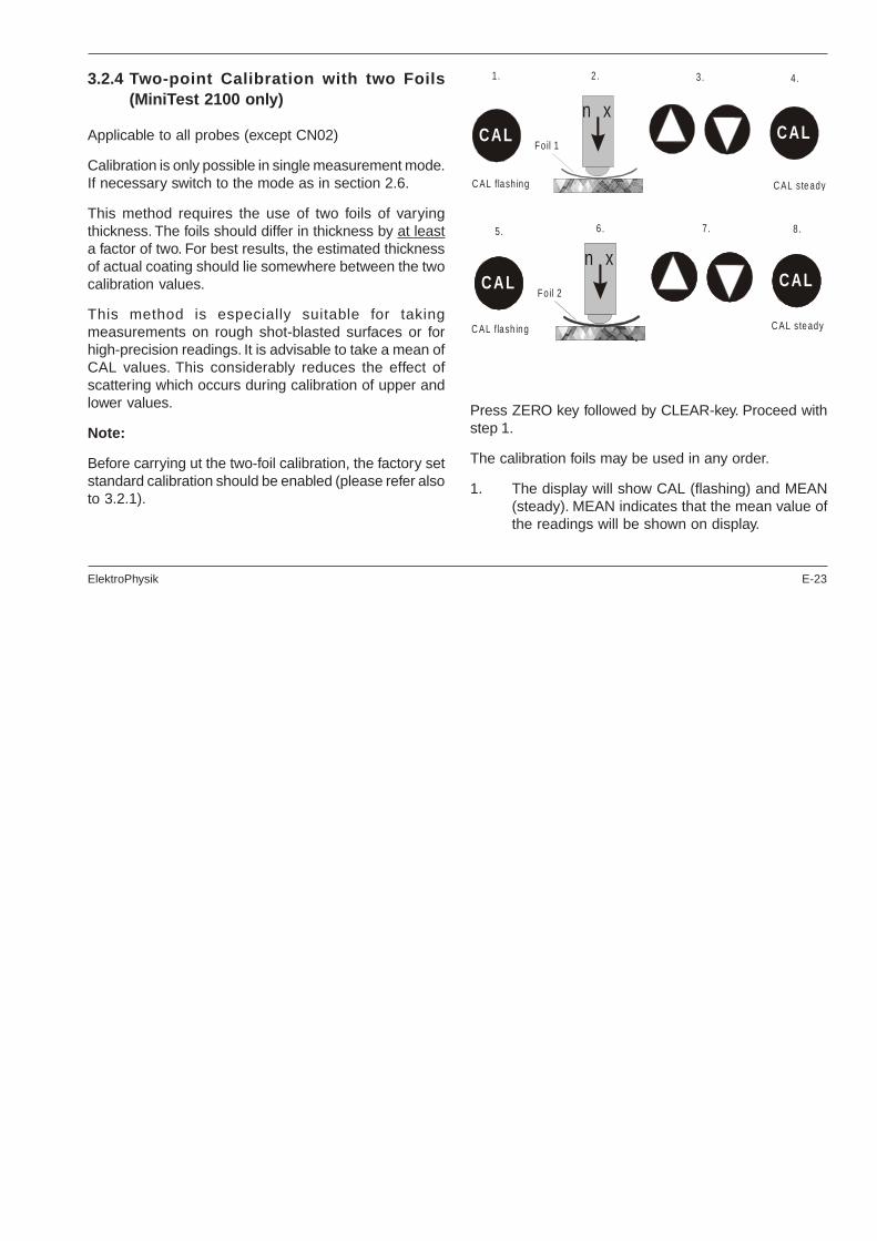
3.2.4 Two-point Calibration with two Foils(MiniTest 2100 only)
Applicable to all probes (except CN02)
Calibration is only possible in single measurement mode.If necessary switch to the mode as in section 2.6.
This method requires the use of two foils of varyingthickness. The foils should differ in thickness by at leasta factor of two. For best results, the estimated thicknessof actual coating should lie somewhere between the twocalibration values.
This method is especially suitable for takingmeasurements on rough shot-blasted surfaces or forhigh-precision readings. It is advisable to take a mean ofCAL values. This considerably reduces the effect ofscattering which occurs during calibration of upper andlower values.
Note:
Before carrying ut the two-foil calibration, the factory setstandard calibration should be enabled (please refer alsoto 3.2.1).
Press ZERO key followed by CLEAR-key. Proceed withstep 1.
The calibration foils may be used in any order.
1. The display will show CAL (flashing) and MEAN(steady). MEAN indicates that the mean value ofthe readings will be shown on display.
CALFoil 1
CAL
C AL flash ing C AL steady
1. 2. 3. 4.
n x
CAL CAL
8.
n xCAL
Foil 2CAL
C AL flash ing C AL steady
5. 6. 7.
n x

E-24 ElektroPhysik
2. Place the thinner of the two foils (e.g. approx.20...30µm) on the uncoated test sample, applythe probe and raise it after the bleep. Repeat thisprocedure several times. The display alwaysshows the mean value of the previous readings.
To discontinue calibration, press CLEAR.
3. Use Arrow key to adjust to the required foilthickness.
4. Press CAL key. ‘CAL’ appears on display (steady).
5. Press CAL to initialise calibration with the secondfoil. This step must follow straight on from step 5.The gauge will not accept readings until CAL hasbeen pressed.
The LC display will show the CAL (flashing) andMEAN (steady). MEAN indicates that the meanvalue of the readings will be shown on the display
6. Place the thicker of the two foils (this should beat least twice as thick as the other foil) on theuncoated sample, apply the probe and raise itafter the bleep.
To discontinue calibration, press CLEAR.
7. Use Arrow key to adjust to the required foilthickness.
8. Press CAL key. ‘CAL’ appears on display (steady).
9. Now take readings by placing the probe on theunknown coating and raising it after the bleep.The reading is shown on display.
t may be necessary to delete CAL calibration, e.g. afterentry of a faulty calibration value:
a) Press CAL key followed by CLEAR key. Both CALcalibrations will be deleted.
Note:
This will reactivate the default standard calibration foruse on even surfaces.
b) Restart CAL calibration by repeating the steps 2-9 asabove. This automatically overwrites the old calibrationand saves the new values.

ElektroPhysik E-25
3.2.5 CTC: Calibration Through the Coating(MiniTest 2100 only)
(CTC: Procedure according licence patentDE3404720C2)
This method is recommended when an uncoated testsample is not available. It can be employed with the pro-be types F06, F1.6, F3, FN1.6 and FN2 (F-part), F1.6/90, F2/90, F10, F20 and F50.
The CTC method may, however, only be used when thecoating is smooth at the calibration point and measuredvalues are reproducible. Do not use for textured coatings.
1. Press FUNC key.
2. Then CAL / CTC to initialise CTC calibration.Display will show CTC (flashing) and MEAN(steady). MEAN indicates that the mean value ofthe readings will be shown on the display.
3. Place the probe on the calibration point of thetest sample and raise it after the bleep. Repeatthis procedure several times. The display alwaysshows the mean value of the previous readings
4. Press CAL key.
5. Lay the calibration foil on the same point, applythe probe and raise it after the bleep.The thicknessof the foil should be roughly equivalent to theestimated coating thickness. Apply the probe tothe test sample several times. The display alwaysshows the mean value of the previous readings.To discontinue calibration, press CLEAR.
6. Use Arrow keys to adjust to the required foilthickness.
7. Press CAL to confirm calibration. CTC will appearon the display (steady).
C A L s teady.
1 . 2 . 3 . 4 .
n x
C TC s teady.
5 . 6 . 7 .
CTCCA L
C TC flash in g
n xn x
F oil
FUN CCTCCA L
CTCCA L

E-26 ElektroPhysik
8. Now take readings by placing the probe on theunknown coating and raising it after the bleep.The reading is shown on display.
It may be necessary to delete CTC calibration, e.g. afterentry of a faulty calibration value:
a) Press FUNC key followed by CLEAR key. CTCcalibration will be deleted.
Note:
This will reactivate the default standard calibration foruse on even surfaces.
b) Restart CTC calibration by repeating the steps 1-6 asabove. This automatically overwrites the old calibrationand saves the new values.
3.2.6 Dual Probes FN
The FN dual probes can work on both, the magneticinduction and the eddy current principle.To select themeasuring procedure, press ON. FERROUS will flashon screen. Press the UP Arrow key to select FERROUS,i.e. the magnetic induction method. Press the DOWNArrow key to select NON-FERROUS, i.e. the eddy current
method. If you make no selection at all, the gauge willautomatically display FERROUS after about 5 secs. andselect the magnetic induction method.
For calibration and measurement, proceed as usualaccording to either 3.2.2 or 3.2.3 or 3.2.4 or (for themagnetic induction principle) 3.2.5.
3.2.7 N10 and N20 Probes
During calibration with N10 and N20 probes the dielectriccharacteristics of the calibration standard and of thecoating material must be taken into consideration.
Switch the gauge on. The gauge automatically switchesto „Continuous Mode“. This mode will be of advantagewhen measuring with the N10 and N20 probes. The„Continuous Mode“ will be indicated by a flashingmeasuring unit (µm, mm, cm). Readings beyond themeasuring range will be indicated by 4 strokes flashing(- - - -).
To switch to „Single measurement mode“ press FUNCfollowed by CONTINUE.
Standardization (Acquisition of Infinite Value)
Place the probe on the thicker of the two suppliedstandards, without any metal underneath. To avoid any

ElektroPhysik E-27
external dielectric influences, an effective base for thestandard is a polystyrene block at least 3cm in thickness.
Press FUNC followed by ZERO key.
Zeroing / Calibrating
For calibrating an zeroing please proceed as describedin section 3.2.2., 3.2.3. or 3.2.4.
(Calibration according to 3.2.3.)
Eliminating the effects of dielectric influence of thecoating material.
Place the probe on the coating material without a metalbase. Press FUNC and followed by ZERO.
Note:
This deactivates the automatic temperaturecompensation feature. Recalibrate in case of changesin temperature.
3.2.8 N100 Probe
For coating or wall thickness measurement with the N100probe, the base material can be of ferrous or non-ferrousmetal.
The base must be a minimum 30x30 cm. With smallerareas, the measuring tolerance will be greater. Forminimum error the following is recommended:
a) For calibration choose a spacer whose thicknessis similar to the expected coating or wall thicknessrespectively (see following calibration principle).
1. 2 . 3 .
FUN C
S tyropor
Calib ra tion standard
ZERO
ZERO steady
4. 5. 6.
CAL steady
7. 8. 9.
Zeroing
CTCC A L
ZERO
���
���
ZERO
CAL flash ing
CTCC A L
10.

E-28 ElektroPhysik
b) Make a two point calibration (3.2.4) with twospacers. Here the expected thickness should liebetween that of the two spacers.
1. Switch the gauge on. The gauge automaticallyswitches to „Continuous Mode“. This mode will beof advantage when measuring with this probe. The„Continuous Mode“ will be indicated by a flashingmeasuring unit (µm, mm, cm). Readings beyondthe measuring range will be indicated by 4 strokesflashing (- - - -).
To switch to „Single measurement mode“ pressFUNC followed by CONTINUE.
2. Standardization (Acquisition of Infinite Value)
Hold probe in the air and press FUNC followed byZERO
3. Zeroing
Press ZERO and place the probe on the zeroplate. ZERO flashes and a bleep soundsrepeatedly. Press ZERO again. ZERO stopsflashing and the bleep stops. Display shows 0.0mm.
4. Calibrating
Press CAL.CAL flashes and there is a repeated bleep.
1. 2. 3.
FUN C ZERO
1. 2. 3.
ZEROZERO
Zero flash ing Ze ro steady
Ze ro plate
1. 2 . 3 .
C AL s teady
CTCCAL
Zero p la te
C AL flash ing
3.
C TCCAL

ElektroPhysik E-29
Place the spacer supplied - e.g. 50 mm - in the recess inthe base of the probe. The thickness of the spacer shouldbe similar to that of the expected thickness to bemeasured. Adjust to the spacer thickness with arrow keys.
Place both together on the measuring reflector. The pro-be base must be held parallel to the measuring reflector.
Use Arrow keys to adjust to the value specified on thespacer, e.g. 50 mm.
Press CAL to confirm. CAL appears on display (steady).
5. Eliminating the effects of dielectric interferenceof the coating material
After entering calibration values, the probe must beplaced on the material - minimum thickness 30mm, butwithout a metal base.
Now press FUNC and ZERO one after the other.
This procedure must be carried out for both calibrationmethods a) (page 27) and b) (page 28). Now the gaugeis ready for operation.
Note:
It is recommended that you check and repeat thecalibration occasionally, e.g. after using the gauge formore than two hours or in case of variations oftemperature of more than 10°C.
If the gauge is to be used on other types of material,point 5 „Eliminating...“ must be repeated
3.2.9 F20 Probe
Switch the gauge on. The gauge automatically switchesto „Continuous Mode“. This mode will be of advantagewhen measuring with this probe. The „Continuous Mode“will be indicated by a flashing measuring unit (µm, mm,cm). Readings beyond the measuring range will beindicated by 4 strokes flashing (- - - -).
1. 2. 3.
FUNC ZERO

E-30 ElektroPhysik
Hold the probe in the air and pres FUNC followed byZERO. The probe will be drift and temperaturecompensated.
Please follow the instructions as described under 3.1‘General Remarks on Calibration’ and 3.2 ‘Special Hintsfor Calibration’.
Place the probe on the sample to be measured. Ifnecessary, store reading into the statistics memory bypressing UP Arrow key (see section 2.5.5 and 2.5.6; onlyrefers to MiniTest 2100).
Note: If the display backlight function is enable incontinuous mode, battery consumption is higher.enabled.
3.2.10 F50 Probe
Switch the gauge on. The gauge automatically switchesto „Continuous Mode“. This mode will be of advantagewhen measuring with this probe. The „Continuous Mode“will be indicated by a flashing measuring unit (µm, mm,cm). Readings beyond the measuring range will beindicated by 4 strokes flashing (- - - -).
Notes on calbration and measurement using F50 probe:Use the calibration and measurement routines of this
instruction manual. In addition, the following remarksshould be observed:
The position of the probe influences the measuring result.The infinite value automatically taken by the instrumentor probe must be taken from the same angle to themeasuring object as the reading which is to be takenlater on. Further, the probe must be moved at a constantspeed towards the measuring object.
In order to avoid hysteresis errors, after eachmeasurement, the probe must be held away from themeasuring object ensuring a minimum distance of 0.3maway from any metal parts.

ElektroPhysik E-31
Note:
The magnetic field created by the measuring probe mightinterfere with or even destroy electronic or medicalequipment or gauges in the vicinity. To avoid suchinterference, it is recommended to keep a distance of aleast 1m away from such instruments or any magneticdata carrier.
3.2.11 Tube probes F1.6/90, F2/90, N1.6/90 andN2/90
In single measurement mode, proceed as normal forcalibration and measurement. In continuousmeasurement mode, the use of tube probes requires aslightly different procedure:
Calibration should be carried out in single measurementmode according to section 3.0. For F1.6/90 and F2/90probes, you can also proceed according to 3.2.5.
Then proceed according to 2.6.
You can switch from single measurement mode tocontinuous mode by pressing „FUNC“ and „CONTINUE“.
3.2.12 Chrome Coatings on Copper
Applicable to probe N08C. Requires to use a specialcalibration foil.
1. The two-point calibration method described in3.2.3 must be used.
2. Use the special calibration foil marked ‘Chromeon Cu‘.
3.2.13 CN02 Probe
The CN02 is a flat probe for use on even surfaces.Onlyone-point calibration using one calibration foil is required.
To measure the thickness of copper laminates or copperfoil:
1. Press CAL to initialise calibration. The LC displaywill show CAL (flashing) and MEAN (steady).MEAN indicates that the mean value of thereadings will be shown on the display.
2. Place the metalic calibration foil on an insulatingpiece of minimum 10mm thickness, apply the pro-be and raise it after the bleep.The thickness ofthe foil should be roughly equivalent to theestimated sample thickness. Apply the probe to

E-32 ElektroPhysik
the metallic calibration foil several times. Thedisplay always shows the mean value calculatedfrom the previous readings.
3. Use Arrow keys to adjust to the foil thickness.
4. Press CA. ‘CAL’ appears (steady).
5. Place the probe to the layer to be measured. Waitfor the bleep and raise the probe.
Important:
Measurements on double-sided laminated PC boardswill require calibration using a double sided laminatedcopper standard or use the correction diagram (availableon request).
3.2.14 Shot-blasted Surfaces
The physical nature of shot-blasted surfaces results incoating thickness readings that are too high. The meanthickness over the peaks can be determined as follows(note that the statistics program is of great benefit in thisprocedure):
Method A (Rz > 20µm)
1. The gauge should be calibrated according to 3.2.2or 3.2.3. Use a smooth calibration sample with
the same curvature radius and the same substrateas the later measuring sample.
2. Now take approx. 10 readings on the uncoated,shot-blasted sample to produce the mean valueXo .
3. After this take approx. 10 further readings on thecoated and similarly shot blasted test sample toproduce the mean value Xm.
4. The difference between the two mean values isthe mean coating thickness Xeff over the peaks.The the greater standard deviation s of the twovalues Xm and Xo should also be taken intoconsideration:
Xeff = ( )Xm Xo s− ±
Method B (Rz < 20µm)
1. Carry out a zero calibration of 10 readings on ashot-blasted, uncoated sample. Then calibratewith a foil on the uncoated substrate. The foil setshould consist of a number of individual foils ofmax. 50 microns thickness each and shouldroughly correspond to the estimated coatingthickness.
ElektroPhysik E-33
2. The coating thickness can be read directly andshould be averaged from 5...10 singlemeasurements. The statistics function is usefulhere.
Method C (MiniTest 2100 only)
Calibration with two different calibration foils.
This method also gives reliable results. Simply follow thetwo-point calibration method using two foils as describedin section 3.2.4.
For a maximum approach to the respective nature ofsurface, the foil value can be reached by using severalfoils - 50µm each.The mean coating thickness shouldbe calculated from between 5 and 10 readings. Thestatistics programme can be useful here.
Note:
For coatings over 300 µm thickness, the influence ofroughness generally is of no importance and it will notbe necessary to apply above calibration methods.
3.2.15 Adjusting to Basic Calibration
In certain cases it can be of assistance or even impera-tive to reset the basic probe calibration e.g.
· if the probe tip is worn
· for special applications
The basic calibration can be adjusted to your specificrequirement. Please contact ElektroPhysik.
3.3 General Remarks on Measurement
After careful calibration has been made all subsequentmeasurements will lie within the guaranteed measuringtolerance (see technical data).
Strong magnetic fields near generators or live rails withstrong currents can affect the reading.
When using the statistic programme (MiniTest2100 only)for obtaining a mean value it is advisable to place theprobe several times at a typical measuring spot. Anyfalse or erratic readings can be cleared immediately bypressing CLEAR.
E-34 ElektroPhysik
The final reading derives from the statistical calculationand from the guaranteed tolerance levels of the gauge.
Coating Thickness D = X s u± ±
Example:
Readings: 150 µm, 156µm, 153 µm
Mean value: X = 153 µm
Standard deviation: s = ± 3 µm
Measuring uncertainty: u = ± (1% of readingt + 1µm)*
* referred to the supplied standards under laboratoryconditions
D = 153µm ± 3µm ± (1,53 µm + 1µm)
= 153 µm ± 5,5µm
3.4 Using the Foot-Operated Switch
In continuous mode, readings are logged to statisticsmemory by pressing UP-Arrow key or by operating thefoot-switch. Data can also be printed-out on an optionalprinter or transferred to a PC via an interface. The foot-
swtich is especially helpful if the operator needs bothhands for measurement, as when using the probes forinternal tube measurement.
4. Measurement Using StatisticsThis section only refers to MiniTest 2100.
The MiniTest 2100 gauge is equipped with two statisticsprograms. One is based on single-value statistics, theother on block-value (DIN 50982).
The MiniTest 2100 can calculate both single-value andblock-value statistics from a maximum of 10,000 singlereadings. The statistical values can be printed out eitherwith or without a list of corresponding single values (see4.5, 4.6, 4.7).
Single Value Statistics:
This program automatically stores and evaluates thereadings of a series of measurements. The analysis ofany one series appears on the display and on the print-out as follows:
n-values : number of single readings
mean ( x ) : mean calculated from a series ofsingle readings

ElektroPhysik E-35
st.d. (s) : standard deviation
kvar : variation coefficient
max : maximum single reading
min : minimum single reading
Block Value Statistics:
(see also 2.5.4 Single Value / Block Value Statistics)
The MiniTest 2100 and is provided with the block-valuestatistics program. In this mode the readings of a seriesare logged in blocks. The size of a block is alterable viaPC and optional software. Default: 5 readings = 1 block.For calculating the statistics over the blocks, the meanvalue ( x ) of the relevant blocks are used. The analysisof any one series appears on the display and on theprint-out as follows:
N-Groups : number of blocks or groups
MEAN ( x ) : mean calculated from mean values
ST.D (s) : standard deviation (mean value)
KVAR : variation coefficient (mean value)
MAX : maximum reading of all blocks
MIN : minimum reading of all blocks
After each block has been registered (default after every5th reading) the gauge emits a double bleep.
At least 2 single values or 2 block values are required toproduce a statistical analysis, which will consist of the 6values listed above.
4.1 Statistical Terms
Mean value : ( x )
The sum of single readings divided by the number ofreadings.
xx
n=
∑
Standard Deviation s (STD. DEV.):
The sample standard deviation is a statistic thatmeasures how „spread out“ the sample is around thesample mean. The sample standard deviation increaseswith increasing spread out. The standard deviation of aset of numbers is the root mean square of the variances².

E-36 ElektroPhysik
The variance of a list is the square of the standarddeviation of the list, that is, the average of the squares ofthe deviations of the numbers in the list from their meandivided by the (number of readings - 1).
Variance sx xn
22
1=
−−
∑( )
Standard deviation s s= 2
Variation coefficient Kvar
The variation coefficient „Kvar“ is the Standard Deviati-on of a set of samples divided by its Mean. The result isexpressed as a percentage.
Ksx
var %= ×100
4.2 Entering a Series of Readings forStatistics Calculation
1. The gauge is ready for measurement immediatelyafter switch-on. All readings will be automaticallylogged to the statistics program.
2. Remember to check whether a recalibration isrequired and/or if any redundant statistical valuesneed to be erased
3. To recalibrate, simply overwrite the old calibration.
4. Any remaining statistical values can be erasedby pressing FUNC and CLEAR STATS.
4.3 Deleting an Erratic or False Reading
Deletion must take place immediately after a faultymeasurement hs been taken i.e. before taking the nextone (see also section 5).
Press CLEAR once. A bleep confirms that the lastregistered value has been deleted.
4.4 Storage Capacity Overflow
If the storage capacity is exceeded the statistics will notbe updated, although measurement can continue.If thememory is full, subsequent readings will be omitted fromthe statistics. They will be marked with the error messageE11.
ElektroPhysik E-37
4.5 Display and Print-out of the Statisticsof a Measuring Series
4.5.1 Single value statistics
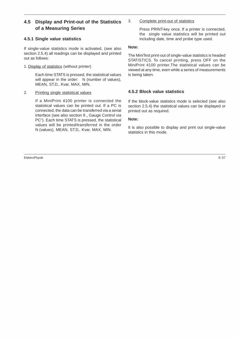
If single-value statistics mode is activated, (see alsosection 2.5.4) all readings can be displayed and printedout as follows:
1. Display of statistics (without printer)
Each time STATS is pressed, the statistical valueswill appear in the order: N (number of values),MEAN, ST.D., Kvar, MAX, MIN.
2. Printing single statistical values
If a MiniPrint 4100 printer is connected thestatistical values can be printed out. If a PC isconnected, the data can be transferred via a serialinterface (see also section 9 „ Gauge Control viaPC“). Each time STATS is pressed, the statisticalvalues will be printed/transferred in the orderN (values), MEAN, ST.D., Kvar, MAX, MIN.
3. Complete print-out of statistics
Press PRINT-key once. If a printer is connected,the single value statistics will be printed outincluding date, time and probe type used.
Note:
The MiniTest print-out of single-value statistics is headedSTATISTICS. To cancel printing, press OFF on theMiniPrint 4100 printer.The statistical values can beviewed at any time, even while a series of measurementsis being taken.
4.5.2 Block value statistics
If the block-value statistics mode is selected (see alsosection 2.5.4) the statistical values can be displayed orprinted out as required.
Note:
It is also possible to display and print out single-valuestatistics in this mode.

E-38 ElektroPhysik
1. Display of single-value statistics
Each time STATS is pressed the statistical valueswill appear in the order N (values), MEAN, ST.D.,Kvar, MAX, MIN.
2. Printing single-value statistics
If a MiniPrint 4100 printer is connected thestatistical values can be printed out. If a PC isconnected, the data can be transferred via a serialinterface (see also section 9 „PC Control“. Eachtime STATS is pressed, the statistical values willbe printed or transferred accordingly.
3. Display of block-value statistics ( without printer)
Press PRINT once. The 6 block-value statisticswill appear for just over a second at a time in theorder N (groups), MEAN, ST.D., Kvar, MAX, MIN.
4. Display of block-value statistics and print out allstatistical values
Press PRINT once.The 6 block-value statistics willbe displayed for just a second at a time. If a printeris connected to the gauge it will simultaneouslyprint out the block-value statistics with date, timeand probe type used.
Note:
The MiniPrint print-out of block-value statistics is headed:BLOCK-STATISTICS.
To cancel printing, press OFF on the MiniPrint 4100printer. The statistical values can be viewed at any time,even while a series of measurements is being taken.
4.6 Print-out of all Statistical Values andReadings of a Series of Measurements
4.6.1 Single value statistics
If single-value statistics mode is activated, (see alsosection 2.5.4) all individual readings of a series and theaccompanying statistics can be displayed and printedout as follows:
Press FUNC and PRINT ALL.
If a printer is connected, all readings of a measuringseries including the 6 single-statistics values will beprinted out.

ElektroPhysik E-39
Note:
1. Pressing FUNC and PRINT ALL will result in aprint-out of all readings and statistical values.
2. Pressing PRINT will result in a print-out ofstatistical values.
3. Press Off on the MiniPrint 4100 printer to cancelthe print-out of readings.
4. The readings on the display and the print-out arerounded off.
4.6.2 Block value statistics
If block-value statistics mode is activated. (See alsosection 2.5.4) the corresponding statistical values andall individual readings of a series can be displayed andprinted out as follows:
1. Display all block-value statistics (without printer)
Press FUNC and PRINT-ALL. The 6 (8) block-statistics values will appear for just over a secondat a time in the order N (groups), MEAN, ST.D.,Kvar, MAX, MIN.
2. Print-out of all readings of a series, the statisticsof each block and all block-value statistics.
Press FUNC and PRINT-ALL.
If a printer is connected, all readings of a series, MEAN,St.D and 6 block statistic readings will be printed out.
Note:
1. Pressing FUNC and PRINT-ALL will result in aprint-out of all readings and statistical values
2. Pressing PRINT will result in a print-out ofstatistical values.
3. Press Off on the MiniPrint 4100 printer to cancelthe print-out of readings.
4. The readings on the display and the print-out arerounded off.

E-40 ElektroPhysik
Table Single Value Statistics and Block Value Statistics
Key Single Value Statistics Block Value Statistics
Display Print-out Display Print-out
STATS
Single valuestatistics eachtime you pressSTATS.
Single valuestatistics each timeyou press STATS.
Single valuestatistics eachtime you pressSTATS.
Single valuestatistics eachtime you pressSTATS.
PRINT --Single valuestatistics includingdate and time.
Block valuestatistics arecontinuouslydisplayed for 1sec. at a time.
Block valuestatistics includingdate and time
PRINTALL
--
All readings of ameasuring series,single valuestatistics incl. dateand time.
Block valuestatistics arecontinuouslydisplayed for 1sec. at a time.
All readings of ameasuring series,block valuestatistics incl. dateand time.

ElektroPhysik E-41
Print-out of Single Value Statistics 5. Delete Functions
5.1 Deleting the last Reading:
Press the CLEAR-key once immediately after a readinghas been taken. A short bleep confirms the reading hasbeen deleted.
5.2 Deleting Data Memory (Statistical andMeasuring Values)
MiniTest 2100
Press both keys simultaneously. A short bleep confirmsdeletion.
LÖSCHContinue
CLR
M in iTes t 1100
LÖSCHCLR STATS
CLR
M in iTes t 2100
LÖSCHCLR STATS
CLRFU NC �
ElektroPhysikSTATS- PROGRAM
02-Mar-02 09:41
Probe F302-Mar-02 07:35
STATISTICS
N-Val 20
Mean 124.6 µm
St. D 9.1%
kvar 2,1%
Max 150.6 µm
Min 104.2 µm
D ate o f p rin t-out
P robe typeD a te o f 1s t read ing
N um ber of readings
M ean
S tanda rd dev ia tion
Variation coe ffic ient
M axim um read ing
M inim um read ing

E-42 ElektroPhysik
5.3 Deleting Calibration, Measuring andStatistical Values, Total Reset
1. Switch the gauge off.
2. Press and hold down the CLEAR, FUNC and ONkeys. Press these keys one after the other andhold all three down.
A long bleep confirms deletion of all data.
6. Using the Gauge without ProbeCertain gauge functions can be activated without a pro-be being connected. These are as follows:
1. Defining the initialising function and standardgauge settings.
2. Print-out of statistics and readings
3. Gauge control via a PC (see section 9).
7. MiniPrint 4100 Data PrinterMiniPrint 4100 provides immediate or later (MiniTest 2100only) print-out of all single readings and statistics(MiniTest 2100 only).
1. Plug the printer laterally into the MiniTest gauge.
2. Switch on the MiniTest gauge (ON).
3. Switch MiniPrint 4100 into the requested mode(ON / OFF).
For fur ther details see MiniPrint 4100 operatinginstructions.
LÖ SCHC LR STATS
CLR FU NC
8. Connecting a PCThe MINITEST 1100 and 2100 gauges have acombination interface which can accommodate aMiniPrint 4100 data printer, a Mitutoyo system evaluatorand two-way RS232C interface. The connecting cableand the data transfer program can be used to transfer allreadings and statistics (MiniTest 2100 only) to a PC forfurther processing. The data transfer procedure is thesame as that for data print-out.

ElektroPhysik E-43
Note on the Mitutoyo printer DP1-HS:
As the Mitutoyo printer DP1-HS works on his ownstatistics function, the MiniTest statistics cannot beprinted out with this printer. For that reason, the statisticsprovided by the Mitutoyo printer is different from theMiniTest statistics program.
9. Gauge Control via PCThe two-way interface can be used to control MiniTestgauge functions via a PC keyboard and a PC program.The option of program control enables the gauge to beused both for semi-automatic and fully automaticoperation.For further details consult our special leaflet(interface description). See also section 11.
10. Combination Interface for foot-operated Switch, Bleeper orLamp
This optional interface makes available an external triggermechanism which enters readings in continuous modeinto the statistics program by a foot-operated switch aswell as a reading confirmed signal for a bleeper or alamp.
Length of reading confirmed signal - 0.2 sec.
11. Interface Descriptions forMiniTest and MiniPrint
Available on request.
12. Useful Accessories· Various probes
· Belt-case
· Transparent case protection case
· Twin case for gauge and printer
· MiniPrint 4100 portable data printer
· PC connecting cable
· Program disk: processes MiniTest readings andstatistics. For IBM PC or compatible.
· High-precision stand for measurement on smallparts.
· Mains adapter 230V AC / 12V DC or 110V AC/12V DC
· Accu battery including charger 230V AC or 110VAC

E-44 ElektroPhysik
13. Maintenance and MaintenanceContracts
The MiniTest needs an occasional battery change but isotherwise maintenance-free. It is extremely robust, but,as with any measuring apparatus, it should be handledwith care.
Used batteries must be removed from the gauge withoutdelay. The accumulator batteries in the MiniPrint printerneed regular recharging.
If the customer takes out a maintenance contract thegauge and all supplementary hardware will be servicedannually. We will gladly supply an estimate formaintenance agreement with further details of the serviceguarantee.
14. After-Sales ServicePlease send a damaged or defective gauge to us directlyor forward it via your dealer.
Please enclose a brief error description.
15. Trouble ShootingThe following list of error messages explains how toidentify and eliminate faults. „E“ (E = error).
Faults that cause the gauge to switch off:
E 1 : Probe type incompatible
E 2 : Probe not connected. This message only appearswhen no probe is connected after a Total Reset.
E 3 : Probe defective. This message only appearsimmediately after the gauge is switched on or ifthe probe becomes detached from the socketwhile in use.
E 4 : Probe is giving unreliable readings (e.g. as a resultof strong fluctuations in the magnetic field orreadings taken on soft coatings).
E 5 : Probe was held too near to metal when switchedon.
E 6 : Low battery.
ElektroPhysik E-45
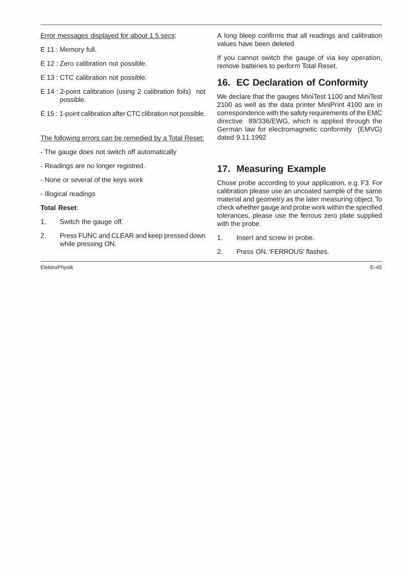
Error messages displayed for about 1.5.secs:
E 11 : Memory full.
E 12 : Zero calibration not possible.
E 13 : CTC calibration not possible.
E 14 : 2-point calibration (using 2 calibration foils) notpossible.
E 15 : 1-point calibration after CTC clibration not possible.
The following errors can be remedied by a Total Reset:
- The gauge does not switch off automatically
- Readings are no longer registred.
- None or several of the keys work
- Illogical readings
Total Reset:
1. Switch the gauge off.
2. Press FUNC and CLEAR and keep pressed downwhile pressing ON.
A long bleep confirms that all readings and calibrationvalues have been deleted
If you cannot switch the gauge of via key operation,remove batteries to perform Total Reset.
16. EC Declaration of ConformityWe declare that the gauges MiniTest 1100 and MiniTest2100 as well as the data printer MiniPrint 4100 are incorrespondence with the safety requirements of the EMCdirective 89/336/EWG, which is applied through theGerman law for electromagnetic conformity (EMVG)dated 9.11.1992
17. Measuring ExampleChose probe according to your application, e.g. F3. Forcalibration please use an uncoated sample of the samematerial and geometry as the later measuring object. Tocheck whether gauge and probe work within the specifiedtolerances, please use the ferrous zero plate suppliedwith the probe.
1. Insert and screw in probe.
2. Press ON. ‘FERROUS’ flashes.
E-46 ElektroPhysik
3. Carry out one-point calibration (zeroing): PressZERO. ‘ZERO’ flashes.
4. Apply the probe serveral times to the zero plate.
5. Press ZERO. ‘ZERO’ appears on display.
6. Now start measurment: Take a calibration foil, layit on the zero plate and place the probe on it severaltimes.The gauge will now display the calibrationfoil thickness, taking into account gaugetolerances.
7. For two-point calibration press CAL. ‘CAL’ appearson display.
8. Place one of the enclosed calibration foils on thezero plate and apply the probe several times.
9. Adjust to the thickness of the foil with the arrowkeys.
10. Press CAL. ‘ZERO’ and ‘CAL’ appear on displayalong with ‘µm’ or ‘mm’.
11. Now take readings on your measuring sample.

ElektroPhysik E-47
18. Technical DataF Probes (Magnetic Induction Principle) - Metric Units
ProbeMeasuring
rangeLow rangesensitivity
Measuring accuracy relatedto the supplied standards
and under laboratoryconditions
Min. curvatureradius (convex/
concave)
Min.measuring
area
Min.substratethickness
Probedimensions
in mm
F05 0...500 µm 0,1 µm ± (1% of reading + 0,7 µm) 0,75 mm / 5 mmØ 3 mm(using stand)
0,1 mm Ø 12 x 49
F1.6 0...1600 µm 0,1 µm ± (1% of reading + 1 µm) 1,5 mm / 10 mm Ø 5 mm 0,5 mm Ø 15 x 62
F3 0...3000 µm 0,2 µm ± (1% of reading + 1 µm) 1,5 mm / 10 mm Ø 5 mm 0,5 mm Ø 15 x 62
F1.6/90Internaltube probe
0...1600 µm 0,1 µm ± (1% of reading + 1 µm) flat / 6 mm Ø 5 mm 0,5 mm 8 x 11 x 180
F1.6PPowderprobe
0...1600 µm 0,1 µm ± (3% of reading + 1 µm) flat surfaces only Ø 30 mmF 0,5 mmN 0,5 mm
Ø 21 x 89
F2/90Internaltube probe
0...2000 µm 0,2 µm ± (1% of reading + 1 µm) flat / 6 mm Ø 5 mm 0,5 mm 8 x 11 x 180
F10 0...10mm 5 µm ± (1% of reading + 10 µm) 5 mm / 16 mm Ø 20 mm 1 mm Ø 25 x 46
F20 0...20 mm 10 µm ± (1% of reading + 10 µm) 10 mm / 30 mm Ø 40 mm 2 mm Ø 40 x 65
F50 0...50 mm 10 µm ± (3% of reading + 50 µm) 50 mm / 200 mm Ø 300 mm 2 mm Ø 45 x 70

E-48 ElektroPhysik
F Probes (Magnetic Induction Principle) - Imperial Units
ProbeMeasuring
rangeLow rangesensitivity
Measuring accuracy related tothe supplied standards andunder laboratory conditions
Min. curvatureradius (convex/
concave)
Min.measuring
area
Min.substratethickness
Probe dimensions
F05 0...20 mils 0.01 mils ± (1% of reading + 0.028 mils) 0.03" / 0.20"Ø 0.12"(using stand)
0.004" Ø 0.47" x 1.93"
F1.6 0...60 mils 0.01 mils ± (1% of reading + 0.04 mils) 0.06" / 0.40" Ø 0.20" 0.020" Ø 0.60" x 2.44"
F1.6P 0...60 mils 0.01 mils ± (3% of reading + 0.4 mils) flat surfaces only Ø 1.20"F 0.02"N 0.02"
Ø 0.83 x 3.50"
F3 0...120 mils 0.01 mils ± (1% of reading + 0.04 mils) 0.06"/ 0.4" Ø 0.20" 20 mils Ø 0.60" x 2.44"
F1.6/90Internaltube probe
0...60 mils 0.01 mils ± (1% of reading + 0.04 mils) flat / 0.24" Ø 0.02" 0.020" 0.32" x 0.43" x 7.09"
F2/90Internaltube probe
0...80 mils 0.01 mils ± (1% of reading + 0.04 mils) flat / 0.24" Ø 0.02" 0.020" 0.32" x 0.43" x 7.09"
F10 0...400 mils 0.5 mils ± (1% of reading + 1 mils) 0.20" / 0.63" Ø 0.80" 0.04" Ø 0.98" x 1.81"
F20 0...800 mils 1 mils ± (1% of reading + 1 mils) 0.40" / 1.2" Ø 1.60" 0.08" Ø 1.57" x 2.55"
F50 0...2 inches 1 mils ± (3% of reading + 2 mils) 2" / 7.9" 12" x 12" 0.08" Ø 1.77" x 2.75"

ElektroPhysik E-49
N Probes (Eddy Currents principle) - Metric Units
ProbeMeasuring
range
Lowrange
sensitivity
Measuring accuracy related tothe supplied standards andunder laboratory conditions
Min. curvatureradius (convex/
concave)
Min.measuring
area
Min.substratethickness
Probedimensions
in mm
N.08Cr 0...80 µm 0,1 µm ± (1% of reading+ 1 µm) 2,5 mm / 10 mm Ø 5 mm ≥100 µm(Cu on steel)
Ø 16 x 70
N02 0...200 µm 0,1 µm ± (1% of reading+ 0,5 µm) 1 mm / 5 mm Ø 0,2 mm 50 µm Ø 16 x 70
N1.6 0...1600 µm 0,1 µm ± (1% of reading + 1 µm) 1,5 mm / 10 mm Ø 5 mm 50 µm Ø 15 x 62
N1.6/90Internal tubeprobe
0...1600 µm 0,1 µm ± (1% of reading + 1 µm) flat / 6 mm Ø 5 mm 50 µm 8 x 11 x 180
N2/90Internal tubeprobe
0...2000 µm 0,2 µm ±( 1% of reading+ 1 µm) flat / 6 mm Ø 5 mm 50 µm 8 x 11 x 180
N10 0...10mm 10 µm ± (1% of reading+ 25 µm) 25 mm / 100 mm Ø 50 mm 50 µm Ø 60 x 50
N20 0...20 mm 10 µm ± (1% of reading + 50 µm) 25 mm / 100 mm Ø 70 mm 50 µm Ø 65 x 75
N100 0...100 mm 100 µm ± (3% of reading + 0,3 mm) 100 mm / eben Ø 200 mm 50 µm Ø 126 x 155
CN02Cu coatingson insulatingsubstrates
10...200 µm 0,2 µm ± (3% of reading + 1 µm) flat surfaces only Ø 7 mmany substratethickness
Ø 17 x 80

E-50 ElektroPhysik
N Probes (Eddy Currents principle) - Imperial Units
ProbeMeasuring
rangeLow rangesensitivity
Measuring accuracy related tothe supplied standards andunder laboratory conditions
Min. curvatureradius (convex/
concave)
Min.measuring
area
Min.substratethickness
Probe dimensions
N.08 Cr 0...3 mils 0.01 mils ± (1% of reading + 0.04 mils) 0.1" / 0.40" Ø 0.20" ≥ 0.004"(Cu on steel)
Ø 0.63" x 2.75"
N02 0...8 mils 0.01 mils ± (1% of reading + 0.20 mils) 0.04" / 0.20" Ø 0.008" 0.002" Ø 0.63" x 2.75"
N1.6 0...60 mils 0.01 mils ± (1% of reading + 0.04 mils) 0.06" / 0.40" Ø 0.20" 0.002" Ø 0.59" x 2.44"
N 1.6/90Internal tubeprobe
0...60 mils 0.01 mils ± (1% of reading + 0.04 mils) flat / 0.25" Ø 0.20" 0.002" 0.32" x 0.43" x 7.09"
N2/90Internal tubeprobe
0...80 mils 0.01 mils ± (1% of reading + 0.04 mils) flat / 0.25" Ø 0.20" 0.002" 0.32" x 0.43" x 7.09"
N10 0...400 mils 0.40 mils ± (1% of reading + 1 mils) 1.0" / 3.94" Ø 1.96" 0.002" Ø 2.36" x 1.96"
N20 0...800 mils 0.40 mils ± (1% of reading + 2 mils) 1.0" / 3.94" Ø 2.75" 0.002" Ø 2.56" x 2.95"
N100 0...4 inches 4.0 mils ± (3% of reading + 12 mils) 3.94" / flat Ø 7.87" 0.002" Ø 4.96" x 6.10"
CN 02Cu coatingson insulatingsubstrates
0.4...8 mils 0.01 mils ± (3% of reading + 0.04 mils) flat surfaces only Ø 0.28"any substratethickness
Ø 0.67" x 3.14"

ElektroPhysik E-51
Dual Probes (Magnetic Induction and Eddy Currents Principle) - Metric Units
ProbeMeasuring
rangeLow rangesensitivity
Measuring accuracyrelated to the suppliedstandards and underlaboratory conditions
Min. curvatureradius (convex/
concave)
Min.measuring
area
Min.substratethickness
Probedimensions
in mm
FN1.6 0...1600 µm 0,1 µm ± (1% of reading + 1 µm) 1,5 mm / 10 mm Ø 5 mmF 0,5 mmN 50 µm
Ø 15 x 62
FN1.6P 0...1600 µm 0,1 µm ± (3% of reading + 1 µm)flat surfacesonly
Ø 30 mmF 0,5 mmN 0,5mm
Ø 21 x 89
FN 1.6 / 90Internaltube probe
0...1600 µm 0,1 µm ± (1% of reading + 1 µm) flat / 6 mm Ø 5 mmF 0,5 mmN 50 µm
8 x 11 x 180
FN2/90Internaltube probe
0...2000 µm 0,2 µm ± (1% of reading + 1 µm) flat / 6 mm Ø 5 mm 0,5 mm 8 x 11 x 180
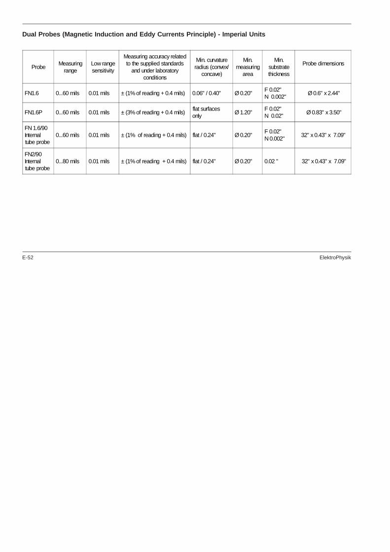
E-52 ElektroPhysik
Dual Probes (Magnetic Induction and Eddy Currents Principle) - Imperial Units
ProbeMeasuring
rangeLow rangesensitivity
Measuring accuracy relatedto the supplied standards
and under laboratoryconditions
Min. curvatureradius (convex/
concave)
Min.measuring
area
Min.substratethickness
Probe dimensions
FN1.6 0...60 mils 0.01 mils ± (1% of reading + 0.4 mils) 0.06" / 0.40" Ø 0.20"F 0.02"N 0.002"
Ø 0.6" x 2.44"
FN1.6P 0...60 mils 0.01 mils ± (3% of reading + 0.4 mils)flat surfacesonly
Ø 1.20"F 0.02"N 0.02"
Ø 0.83" x 3.50"
FN 1.6/90Internaltube probe
0...60 mils 0.01 mils ± (1% of reading + 0.4 mils) flat / 0.24" Ø 0.20"F 0.02"N 0.002"
32" x 0.43" x 7.09"
FN2/90Internaltube probe
0...80 mils 0.01 mils ± (1% of reading + 0.4 mils) flat / 0.24" Ø 0.20" 0.02 " 32" x 0.43" x 7.09"
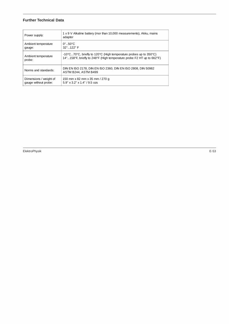
ElektroPhysik E-53
Further Technical Data
Power supply:1 x 9 V Alkaline battery (mor than 10,000 measurements), Akku, mainsadapter
Ambient temperaturegauge:
0°...50°C32°...122° F
Ambient temperatureprobe:
-10°C...70°C, briefly to 120°C (High temperature probes up to 350°C)14°...158°F, briefly to 248°F (High temperature probe F2 HT up to 662°F)
Norms and standards:DIN EN ISO 2178, DIN EN ISO 2360, DIN EN ISO 2808, DIN 50982ASTM B244, ASTM B499
Dimensions / weight ofgauge without probe:
150 mm x 82 mm x 35 mm / 270 g5.9" x 3.2" x 1.4" / 9.5 ozs
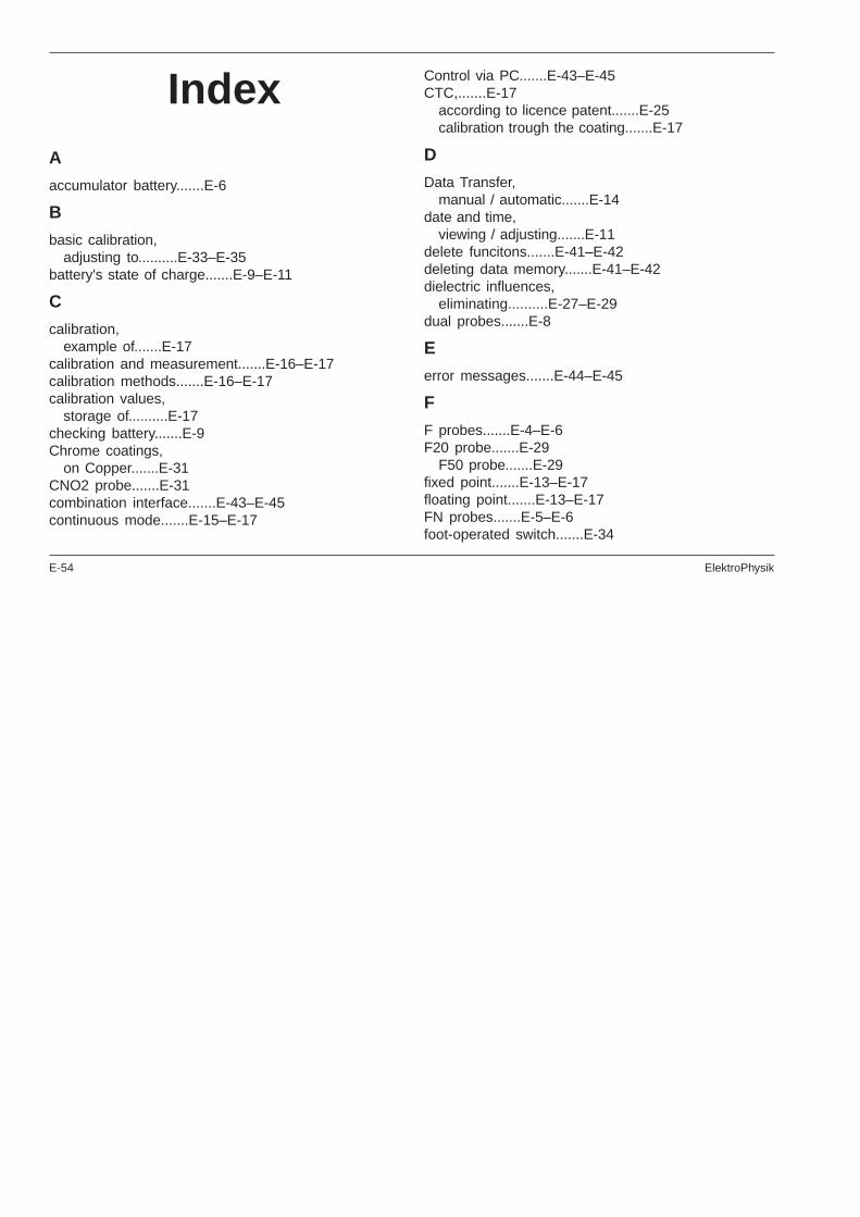
E-54 ElektroPhysik
IndexA
accumulator battery.......E-6
B
basic calibration,adjusting to..........E-33–E-35
battery's state of charge.......E-9–E-11
C
calibration,example of.......E-17
calibration and measurement.......E-16–E-17calibration methods.......E-16–E-17calibration values,
storage of..........E-17checking battery.......E-9Chrome coatings,
on Copper.......E-31CNO2 probe.......E-31combination interface.......E-43–E-45continuous mode.......E-15–E-17
Control via PC.......E-43–E-45CTC,.......E-17
according to licence patent.......E-25calibration trough the coating.......E-17
D
Data Transfer,manual / automatic.......E-14
date and time,viewing / adjusting.......E-11
delete funcitons.......E-41–E-42deleting data memory.......E-41–E-42dielectric influences,
eliminating..........E-27–E-29dual probes.......E-8
E
error messages.......E-44–E-45
F
F probes.......E-4–E-6F20 probe.......E-29
F50 probe.......E-29fixed point.......E-13–E-17floating point.......E-13–E-17FN probes.......E-5–E-6foot-operated switch.......E-34
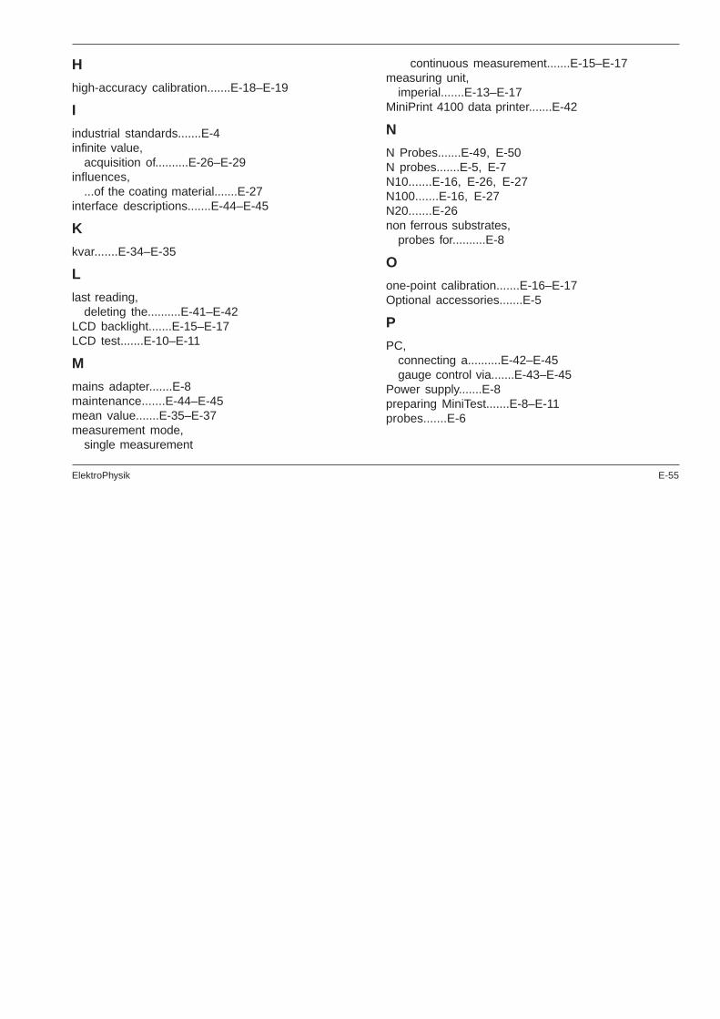
ElektroPhysik E-55
H
high-accuracy calibration.......E-18–E-19
I
industrial standards.......E-4infinite value,
acquisition of..........E-26–E-29influences,
...of the coating material.......E-27interface descriptions.......E-44–E-45
K
kvar.......E-34–E-35
L
last reading,deleting the..........E-41–E-42
LCD backlight.......E-15–E-17LCD test.......E-10–E-11
M
mains adapter.......E-8maintenance.......E-44–E-45mean value.......E-35–E-37measurement mode,
single measurement
continuous measurement.......E-15–E-17measuring unit,
imperial.......E-13–E-17MiniPrint 4100 data printer.......E-42
N
N Probes.......E-49, E-50N probes.......E-5, E-7N10.......E-16, E-26, E-27N100.......E-16, E-27N20.......E-26non ferrous substrates,
probes for..........E-8
O
one-point calibration.......E-16–E-17Optional accessories.......E-5
P
PC,connecting a..........E-42–E-45gauge control via.......E-43–E-45
Power supply.......E-8preparing MiniTest.......E-8–E-11probes.......E-6

E-56 ElektroPhysik
R
replacing battery.......E-9–E-11
S
series of measurements,printing all readings and statistical values of a.......E-
38shot-blasted surfaces.......E-32spring mounted sleeve.......E-6stabilising of readings.......E-14–E-17standard calibration.......E-16–E-17standard calibration,
enable.......E-19standard deviation,
statistical term.......E-35standardization.......E-26–E-29start-up functions.......E-10–E-11statistics,
display and print-out of..........E-37measurement using..........E-34–E-35single value
block value.......E-38Std. dev........E-35–E-37steel substrates,
probes for..........E-7storage capacity,
overflow.......E-36–E-37storage of Min reading,
...in continuous mode.......E-15–E-17supply schedule.......E-5–E-6Switch off mode,
automatic.......E-13
T
Total Reset.......E-42, E-44, E-45Total-Reset.......E-10–E-11tube probe.......E-31Two-Point Calibration.......E-21Two-point Calibration.......E-23Two-point calibration.......E-16two-point calibration.......E-20, E-22, E-31, E-33
U
using one calibration foil.......E-31
V
V-groove.......E-6variance.......E-35, E-36variation coefficient.......E-35, E-36
Z
zeroing.......E-27–E-29

ElektroPhysik E-57


