54
Multi-Converter for FANUC CNC Technical Guide

Multi-Converter for FANUC CNC
Technical Guide

Revision History No. Date Description
00 May 8, 2017 New
01 Jan 29, 2018 Added update procedure to "8.9 Transfer (Project Transfer)".

Table of Contents
Safety Information ........................................................................................................... 1 About the Book ............................................................................................................... 2 1. Overview .................................................................................................................... 3 2. Important Notes .......................................................................................................... 3 3. Device Configuration ..................................................................................................... 4
3.1. System Configuration .............................................................................................. 4 3.2. Compatible CNC ..................................................................................................... 5 3.3. Operating Environment ............................................................................................ 6
3.3.1. Target Confirmation Tool ..................................................................................... 6 3.3.2. User Management Tool ....................................................................................... 7 3.3.3. Compatible Browser ........................................................................................... 7
3.4. Package Contents ................................................................................................... 8 3.5. External Specifications ............................................................................................. 9 3.6. Interface Specifications .......................................................................................... 10
3.6.1. Input Connector Pin Assignment ........................................................................ 11 3.6.2. Digital Inputs .................................................................................................. 13 3.6.3. Analog Inputs ................................................................................................. 13 3.6.4. Serial Communication Settings .......................................................................... 14
3.7. List of supported features ....................................................................................... 14 4. Settings of communication with FANUC CNC ................................................................... 16
4.1. For FS16/18/21 RS-232C settings ............................................................................ 16 4.2. For FS15 RS-232C settings ..................................................................................... 17
5. MT-LINKi AdminTool .................................................................................................... 18 6. Registered variables and node names ............................................................................ 23 7. Tool ......................................................................................................................... 25
7.1. Target Confirmation Tool (IP Address confirmation tool) ............................................... 25 7.1.1. How to confirm the IP Address ........................................................................... 25
7.2. User Management Tool (Security Setting).................................................................. 27 8. Web Browser ............................................................................................................. 30
8.1. Login Screen ........................................................................................................ 31 8.1.1. User Management............................................................................................ 31 8.1.2. Errors at the time of login ................................................................................. 32
8.2. Initial Screen ....................................................................................................... 33 8.3. General (Setting information) ................................................................................. 34 8.4. Date / Time (Date and Time Settings) ...................................................................... 35 8.5. Time Adjustment(Time and Summer Time) ............................................................ 36 8.6. Ethernet Settings .................................................................................................. 37 8.7. OPC UA Server Settings ......................................................................................... 39 8.8. Drivers (RS-232C communication setting) ................................................................. 40 8.9. Transfer (Project Transfer) ...................................................................................... 41 8.10. System Log (System Error Log) ............................................................................. 43 8.11. Analog Input ...................................................................................................... 44 8.12. Digital Input ....................................................................................................... 46 8.13. User Management (Security Settings) ..................................................................... 47
9. Compatibility with the related products .......................................................................... 48 10. Restrictions ............................................................................................................. 48 11. Error Code List ......................................................................................................... 49
1 / 51
Safety Information Important Information Notice
Read these instructions carefully, and look at the equipment to become familiar with the device before trying
to install, operate, or maintain it. The following special messages may appear throughout this documentation
or on the equipment to warn of potential hazards or to call attention to information that clarifies or simplifies
a procedure. For the product related information such as warning and caution, refer to the product’s hardware
manual.
PLEASE NOTE
Electrical equipment should be installed, operated, serviced, and maintained only by qualified personnel. No
responsibility is assumed by Schneider Electric or any of its affiliates or subsidiaries (hereinafter, referred to
as Schneider Electric) for any consequences arising out of the use of this material.
A qualified person is one who has skills and knowledge related to the construction and operation of electrical
equipment and its installation, and has received safety training to recognize and avoid the hazards involved.
Copyright © 2018 Schneider Electric Japan Holdings Ltd. All Rights Reserved.

2 / 51
About the Book Overview Document Scope;
This book describes the following contents.
・ How to connect this product to CNC made by FANUC Corporation
・ How to configure settings using every setting tool
Related manual
Download manuals and technical information from our Web site.
http://www.pro-face.com/trans/en/manual/1001.html

3 / 51
1. Overview This product can collect data from machine tools by communicating with CNC made by FANUC Corporation.
・ Able to transfer operating status of machine tools to MT-LINKi.
・ Able to configure settings of the main unit using settings on the Web browser without a
screen-creation editor.
・ Able to support DPRNT function as serial connection.
2. Important Notes ・ The contents and descriptions of this book are subject to change without notice.
・ This book describes contents dedicated to the product (Multi-Converter for CNC made by FANUC
corporation) that is created with customizing a Pro-face product for FANUC Corporation.
・ For details of the hardware, refer to [LT-4201TM/4301TM/4000M Hardware Manual] or
specifications of ‘PFXLM4B01DAK(model)’ in the [LT-4201TM/4301TM Installation Guide].
<Download>
http://www.pro-face.com/trans/en/manual/1001.html

4 / 51
3. Device Configuration 3.1. System Configuration
*1. When connecting to FANUC CNC, an option cable is separately required. Product Name Model Description FANUC CNC connecting cable (5M)
PFXZLMCBRJR22 A serial communication cable for connecting this product to FANUC CNC
5 / 51
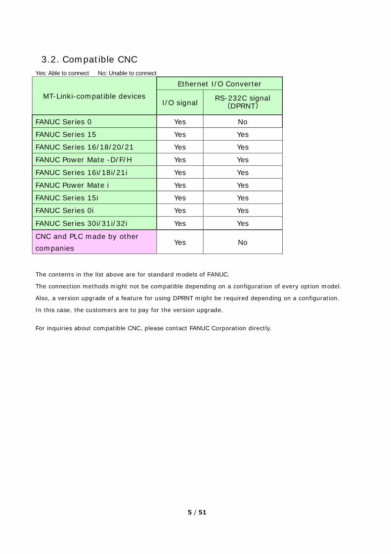
3.2. Compatible CNC Yes: Able to connect No: Unable to connect
MT-Linki-compatible devices
Ethernet I/O Converter
I/O signal RS-232C signal(DPRNT)
FANUC Series 0 Yes No
FANUC Series 15 Yes Yes
FANUC Series 16/18/20/21 Yes Yes
FANUC Power Mate -D/F/H Yes Yes
FANUC Series 16i/18i/21i Yes Yes
FANUC Power Mate i Yes Yes
FANUC Series 15i Yes Yes
FANUC Series 0i Yes Yes
FANUC Series 30i/31i/32i Yes Yes
CNC and PLC made by other companies
Yes No
The contents in the list above are for standard models of FANUC.
The connection methods might not be compatible depending on a configuration of every option model.
Also, a version upgrade of a feature for using DPRNT might be required depending on a configuration.
In this case, the customers are to pay for the version upgrade.
For inquiries about compatible CNC, please contact FANUC Corporation directly.

6 / 51
3.3. Operating Environment 3.3.1. Target Confirmation Tool
Items Definition PC model PC/AT compatible machine Target OS and its version ・Windows 7 32/64 bits (Service Pack 1 or later)
・Windows 8/8.1 32/64 bits ・Windows 10 32/64 bits
Programs required for operation of the product except OS and their versions (for example, FEP)
Required for PC from the beginning
FEP compatible with OS in every country (Global IME)
Need installing .Net Framework 3.0
Other necessary environments None
Target language English only Required disk capacity 50MB or more Required memory capacity (recommended)
Recommended value: 2GB or more
With or without a mouse Necessary Other necessary equipment lists None Restrictions and important notes on the operating environment
None
List of recommended environments CPU: Core2 Duo 2GHz or more Display: SXGA(800×600) or more
256 or more-color display is required.

7 / 51
3.3.2. User Management Tool Items Definition PC model PC/AT compatible machine Target OS and its version ・ Windows 7 32/64 bits (Service Pack 1 or later)
・ Windows 8/8.1 32/64 bits ・ Windows 10 32/64 bits
Programs required for operation of the product except OS and their versions (for example, FEP)
Required for PC from the beginning
FEP compatible with OS in every country (Global IME)
Need installing Microsoft .NET Framework 4.5.2
Other necessary environments ・ None
Target language Japanese / English
Required disk capacity (Max. value, min. value, free space after installation)
・ 50MB or more ・ Free space after installation needs a capacity for binary
data. Required memory capacity (recommended)
・Recommended value: 2GB or more
With or without a mouse ・ Necessary Other necessary equipment lists ・ None Restrictions and important notes on the operating environment
Necessary to install .NET Framework 4.5.2.
List of recommended environments ・ CPU: Core2 Duo 2GHz or more ・ Display: SXGA (800×600) or more
256 or more-color display is required.
3.3.3. Compatible Browser Since the Multi-Converter for FANUC CNC does not have a display, settings cannot be confirmed on the main
unit alone. To confirm the settings, access the Multi-Converter for FANUC CNC from the Web browser and see
the setting status. Items Definition PC model PC/AT compatible machine
Target Browsers and their versions ・ Internet Explorer11 (11.0.***) ・ Google Chrome (55.0.*****)
Other necessary environments ・ None
8 / 51
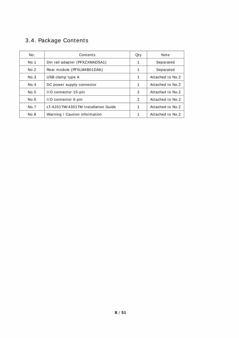
3.4. Package Contents
No. Contents Qty Note
No.1 Din rail adapter (PFXZXMADSA1) 1 Separated
No.2 Rear module (PFXLM4B01DAK) 1 Separated
No.3 USB clamp type A 1 Attached to No.2
No.4 DC power supply connector 1 Attached to No.2
No.5 I/O connector 15-pin 2 Attached to No.2
No.6 I/O connector 6-pin 2 Attached to No.2
No.7 LT-4201TM/4301TM Installation Guide 1 Attached to No.2
No.8 Warning / Caution information 1 Attached to No.2

9 / 51
3.5. External Specifications This shows the external dimensions of the Multi-Converter for FANUC CNC.

10 / 51
3.6. Interface Specifications
Part Name Description
B Rear module
C USB (type A) Interface (USB1) Used for user management or at the time of
data update
D USB (type mini B) Interface Target Confirmation Tool (for the IP Address
confirming tool)
E1 I/O terminal block 1
E2 I/O terminal block 2 Unusable
F DC power supply connecter
G Ethernet Interface
H Serial Link (RS-232C/485)
I CANopen Interface Unusable
J Yellow button lock

11 / 51
3.6.1. Input Connector Pin Assignment
The figure shows the pin assignment of the terminal blocks:
The pins from A1 to A6 and B1 to B6 cannot be used for the Multi-Converter for FANUC CNC.
Pin Arrangement Group Pin SignalName Group Pin Signal
NameA1 V0+ B1 V0-A2 Q1 B2 Q0A3 V1+ B3 V1-A4 Q3 B4 Q2A5 Q5 B5 Q4A6 Q7 B6 Q6
Unusable Unusable

12 / 51
The pins of C8 to C11, D8 to D11, C15, D14, and D15 cannot be used for the Multi-Converter for FANUC CNC.
Pin Arrangement Group Pin Signal Name Group Pin Signal Name
C1 I0 D1 IC0C2 I1 D2 I2C3 I3 D3 IC1C4 I5 D4 I4C5 I7 D5 I6C6 I9 D6 I8C7 I11 D7 I10C8 MS0+ D8 MS0-C9 EX0+ D9 EX0-C10 MS1+ D10 MS1-C11 EX1+ D11 EX1-
C12 IV0 D12 AIC
C13 IV1 D13 IA0
C14 IA1 D14 AOC
Unusable C15 U/I0 D15 U/I1
Standard Input Standard Input
Unusable Unusable
Analog Input
Analog Input
Unusable

13 / 51
3.6.2. Digital Inputs There are 12-point digital inputs. It’s possible to switch between sink inputs and source inputs for connecting
to an external power supply. Refer to the wiring diagram below.
3.6.3. Analog Inputs There are different terminal connection points for different types of analog input signals.
Since current and voltage requires different adjustment values, you need to set the input signals to desired
types:
Analog input signal type
-10...10 Vdc voltage signal (default)
0...10 Vdc voltage signal
0...20 mA current signal
4...20 mA current signal
Connect to pin numbers according to a signal type.
Channel Number
and type
Digital
Resolution
Voltage/Current
2 inputs 13 bits -10...10Vdc (digital value -4096...4095) /0...10Vdc (digital value
0...8191)
0...20mA (digital value 0...8191) /4...20mA (digital value 0...8191)

14 / 51
3.6.4. Serial Communication Settings The table below shows serial communication settings of the Multi-Converter for FANUC CNC.
Items Setting contents Default
Type fixed with RS-232C RS-232C
Baud rate 2400, 4800, 9600, 19200, 38400, 57600, 115200 4800
Data length 7,8 8
Parity NONE,ODD,EVEN NONE
Stop bit 1,2 2
Flow control XON/XOFF XON/XOFF
Timeout 1 to 127 60
Retry 0 to 255 0
Send wait time 0 to 255 0
RI/VCC RI/VCC (fixed with RI) RI
3.7. List of supported features Supported features Contents / Initial Settings
12-point Digital Inputs Able to confirm ON/OFF status of digital inputs.
Cycle: 200ms
2-point Analog Inputs Able to confirm data values of analog inputs.
Cycle: 200ms
Compatible Protocol CNC serial protocol (fixed)
Serial Communication Settings ・ Baud rate: 4800
・ Data length: 8 bits
・ Parity: None
・ Stop bit: 2 bits
・ Flow control: XON/XOFF
・ Timeout: 60 seconds
Upper Communication Feature OPC UA server
・ Port No.: 48010 (default)
・ Protocol: UA TCP,
・ Data format: UA Binary
・ Security: Not supported
・ Certification: Anonymous only
・ Access type
(Read / Write, subscription)
Main Unit Settings Web Configuration Page
15 / 51
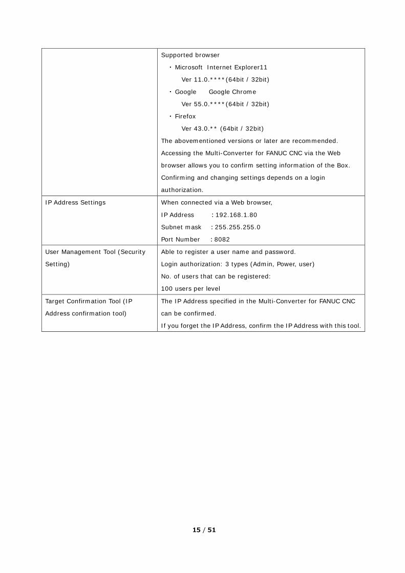
Supported browser
・ Microsoft Internet Explorer11
Ver 11.0.****(64bit / 32bit)
・ Google Google Chrome
Ver 55.0.****(64bit / 32bit)
・ Firefox
Ver 43.0.** (64bit / 32bit)
The abovementioned versions or later are recommended.
Accessing the Multi-Converter for FANUC CNC via the Web
browser allows you to confirm setting information of the Box.
Confirming and changing settings depends on a login
authorization.
IP Address Settings When connected via a Web browser,
IP Address :192.168.1.80
Subnet mask :255.255.255.0
Port Number :8082
User Management Tool (Security
Setting)
Able to register a user name and password.
Login authorization: 3 types (Admin, Power, user)
No. of users that can be registered:
100 users per level
Target Confirmation Tool (IP
Address confirmation tool)
The IP Address specified in the Multi-Converter for FANUC CNC
can be confirmed.
If you forget the IP Address, confirm the IP Address with this tool.
16 / 51
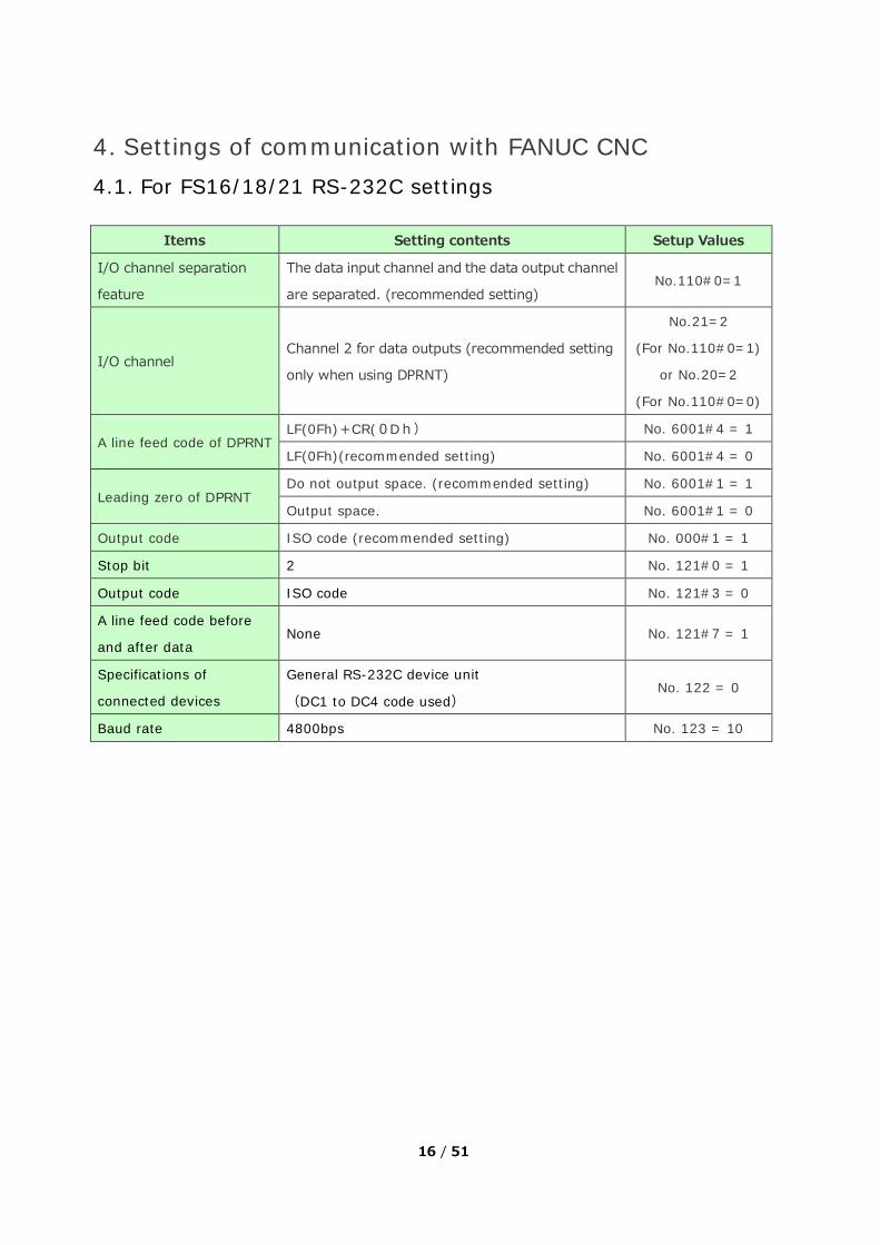
4. Settings of communication with FANUC CNC 4.1. For FS16/18/21 RS-232C settings
Items Setting contents Setup Values
I/O channel separation
feature
The data input channel and the data output channel
are separated. (recommended setting) No.110#0=1
I/O channel Channel 2 for data outputs (recommended setting
only when using DPRNT)
No.21=2
(For No.110#0=1)
or No.20=2
(For No.110#0=0)
A line feed code of DPRNT LF(0Fh)+CR(0Dh) No. 6001#4 = 1
LF(0Fh)(recommended setting) No. 6001#4 = 0
Leading zero of DPRNT Do not output space. (recommended setting) No. 6001#1 = 1
Output space. No. 6001#1 = 0
Output code ISO code (recommended setting) No. 000#1 = 1
Stop bit 2 No. 121#0 = 1
Output code ISO code No. 121#3 = 0
A line feed code before
and after data None No. 121#7 = 1
Specifications of
connected devices
General RS-232C device unit
(DC1 to DC4 code used) No. 122 = 0
Baud rate 4800bps No. 123 = 10

17 / 51
4.2. For FS15 RS-232C settings
Items Setting contents Setup Values
I/O channel Channel 2 for data outputs (recommended setting
only when using DPRNT) No.21=2
A line feed code of DPRNT LF(0Fh)+CR(0Dh)+CR(0Dh) No. 0000#3 = 0
LF(0Fh)(recommended setting) No. 0000#3 = 1
Leading zero of DPRNT Do not output space. (recommended setting) No. 7000#7 = 1
Output space. No. 7000#7 = 0
Output code ISO code & without parity bit (recommended
setting)
No. 0000#2 = 1
No. 0000#4 = 0
Stop bit 2 No. 5161= 2
A line feed code before
and after data None
No setting is
required.
Specifications of
connected devices
General RS-232C device unit
(DC1 to DC4 code used)
No. 5002 = 6
No. 5160 = 3
Baud rate 4800bps No. 5162 = 10
18 / 51
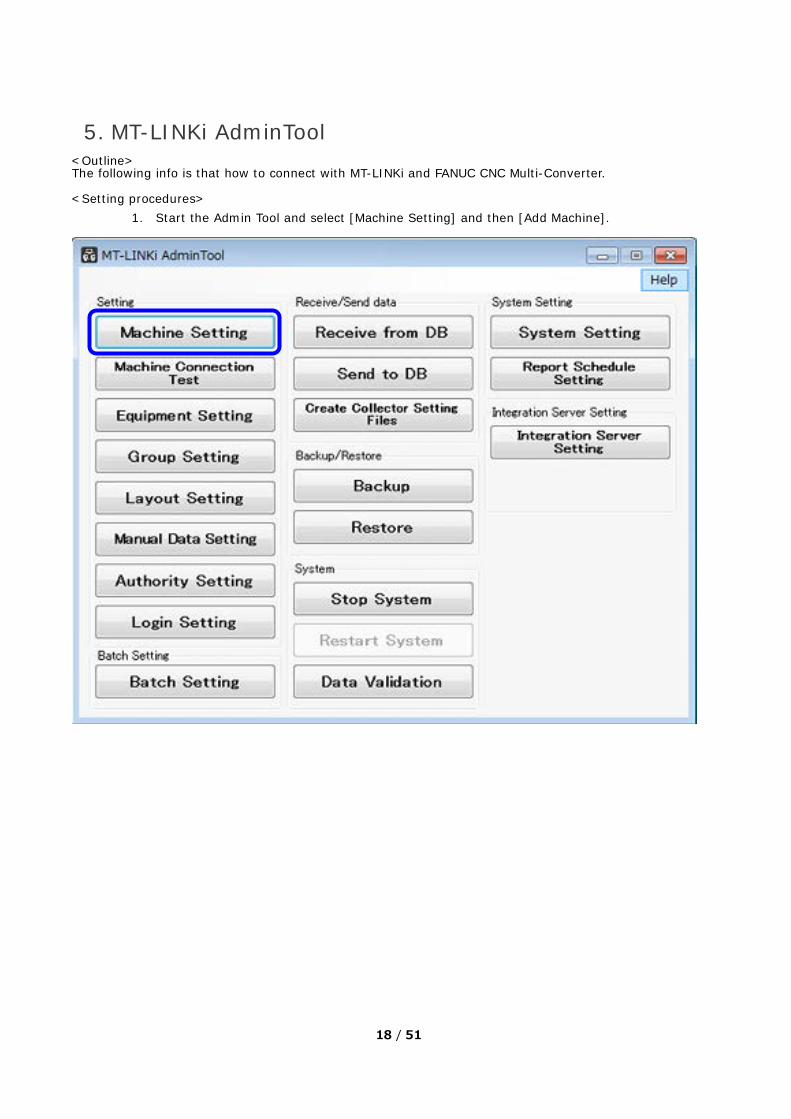
5. MT-LINKi AdminTool <Outline> The following info is that how to connect with MT-LINKi and FANUC CNC Multi-Converter. <Setting procedures>
1. Start the Admin Tool and select [Machine Setting] and then [Add Machine].

19 / 51
2. Select [OPC UA Server] for [Machine Type]. The [Select Machine] dialog box will appear.
20 / 51
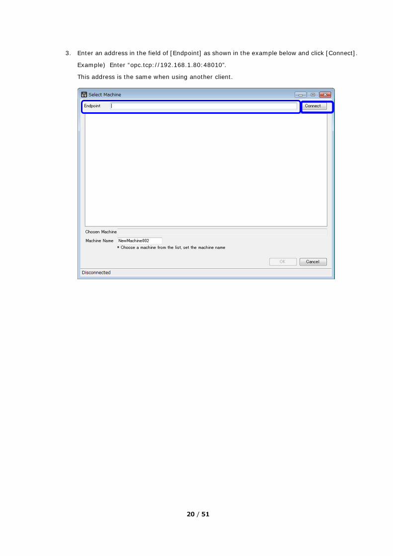
3. Enter an address in the field of [Endpoint] as shown in the example below and click [Connect].
Example) Enter “opc.tcp://192.168.1.80:48010”.
This address is the same when using another client.
21 / 51
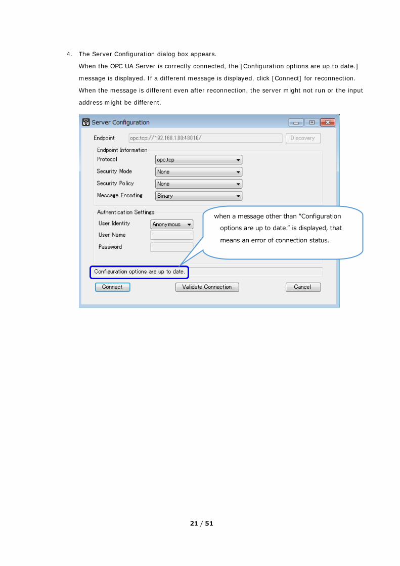
4. The Server Configuration dialog box appears.
When the OPC UA Server is correctly connected, the [Configuration options are up to date.]
message is displayed. If a different message is displayed, click [Connect] for reconnection.
When the message is different even after reconnection, the server might not run or the input
address might be different.
when a message other than “Configuration
options are up to date.” is displayed, that
means an error of connection status.

22 / 51
5. When connection is completed, the node names (variable names) used for the server can
be selected.
Connecting to the OPC UA Server is now completed.

23 / 51
6. Registered variables and node names Digital Inputs
NO, Node name (variable name) Data Type Read / Write
1 DI00 Boolean Read
2 DI01 Boolean Read
3 DI02 Boolean Read
4 DI03 Boolean Read
5 DI04 Boolean Read
6 DI05 Boolean Read
7 DI06 Boolean Read
8 DI07 Boolean Read
9 DI08 Boolean Read
10 DI09 Boolean Read
11 DI10 Boolean Read
12 DI11 Boolean Read Analog Inputs
NO, Node name (variable name) Data Type Read / Write
1 AI00 Int32 Read
2 AI01 Int32 Read DPRNT
NO, Node name (variable name) Data Type Read / Write DPRNT identifier
1 PrintOutput String Read / Write -
2 ProductName String Read / Write PN*
3 ProductResultNumber Int32 Read / Write PC*
4 value01 Double Read / Write VA01*
5 value02 Double Read / Write VA02*
6 value03 Double Read / Write VA03*
7 value04 Double Read / Write VA04*
8 value05 Double Read / Write VA05*
9 value06 Double Read / Write VA06*
10 value07 Double Read / Write VA07*
11 value08 Double Read / Write VA08*
12 value09 Double Read / Write VA09*
13 value10 Double Read / Write VA10*

24 / 51
14 string01 String Read / Write SR01*
15 string02 String Read / Write SR02*
16 string03 String Read / Write SR03*
17 string04 String Read / Write SR04*
18 string05 String Read / Write SR05*
19 string06 String Read / Write SR06*
20 string07 String Read / Write SR07*
21 string08 String Read / Write SR08*
22 string09 String Read / Write SR09*
23 string10 String Read / Write SR10*
25 / 51
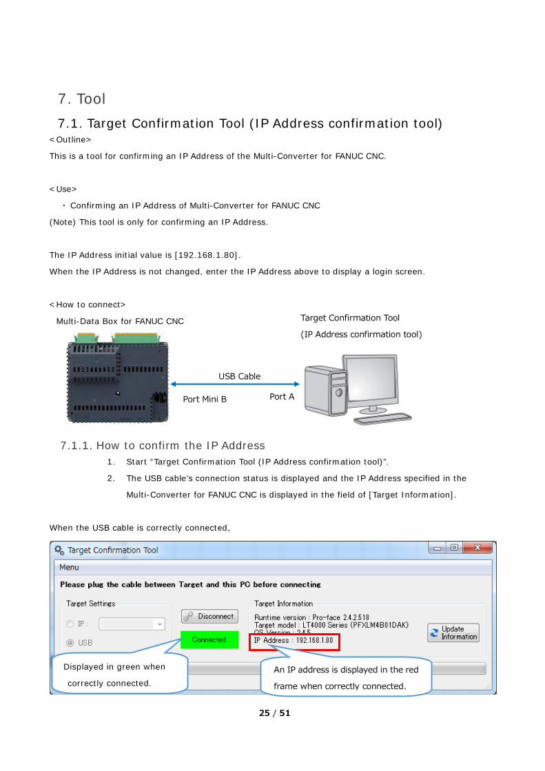
7. Tool 7.1. Target Confirmation Tool (IP Address confirmation tool)
<Outline>
This is a tool for confirming an IP Address of the Multi-Converter for FANUC CNC.
<Use>
・ Confirming an IP Address of Multi-Converter for FANUC CNC
(Note) This tool is only for confirming an IP Address.
The IP Address initial value is [192.168.1.80].
When the IP Address is not changed, enter the IP Address above to display a login screen.
<How to connect>
7.1.1. How to confirm the IP Address 1. Start “Target Confirmation Tool (IP Address confirmation tool)”.
2. The USB cable’s connection status is displayed and the IP Address specified in the
Multi-Converter for FANUC CNC is displayed in the field of [Target Information].
When the USB cable is correctly connected,
USB Cable
Port Mini B Port A
Target Confirmation Tool
(IP Address confirmation tool)
An IP address is displayed in the red
frame when correctly connected.
Displayed in green when
correctly connected.
Multi-Data Box for FANUC CNC

26 / 51
When the USB cable is not correctly connected,
<Menu Screen>
Item Name Description
Target Settings Select how to connect to the Multi-Converter for FANUC CNC.
Disconnect Disconnect communication with the Multi-Converter for FANUC CNC.
Connected Status
Target Information Display device information of the connected Multi-Converter for FANUC CNC.
Update Information Update information at the time of reconnection.
Displayed in red when not
correctly connected.
The IP Address is not displayed in the red
frame when the red color is displayed.

27 / 51
7.2. User Management Tool (Security Setting) <Outline>
This is a tool for registering users who can log in the Multi-Converter for FANUC CNC on a Web browser.
(Note) Microsoft .NET Framework 4.5.2 or later is required for installation.
<Use>
・ Changing a user name
・ Changing a password
・ Changing a security level
<Authorization Feature>
It’s possible to configure authorization settings using 3 levels. Things that can be done differ depending on an
authorization.
1. Admin (administrators)
Able to change all the setting items. Able to change setting contents including the user
management (security).
[Default]
User Name: Admin
Password: Pro-face20
2. Power (power users)
Able to change items other than the user management (security).
[Default] None
3. User (users)
Unable to change settings. Able to monitor I/O status only.
[Default] None

28 / 51
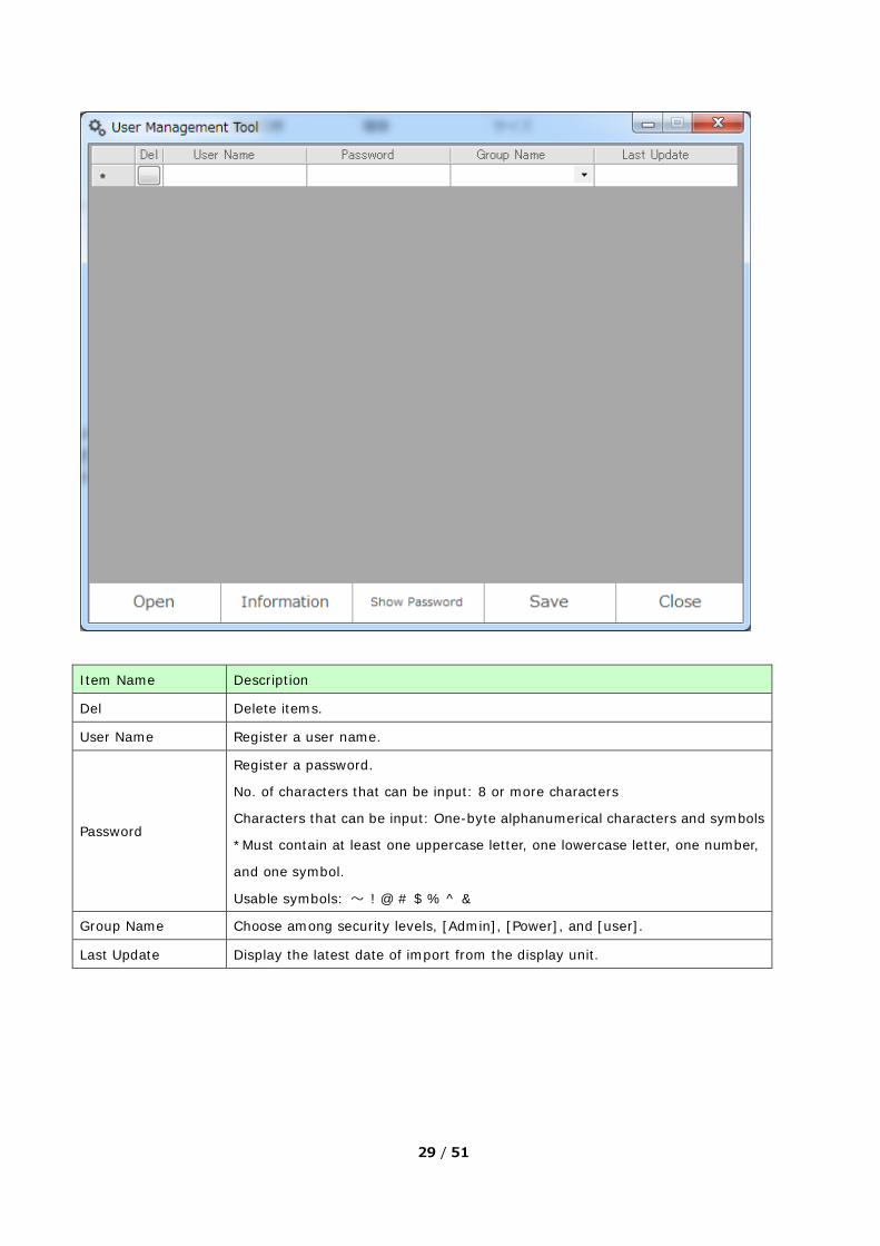
Start ‘UserManagementTool.exe’, and the following tool will start.
<Setting Procedure>
1. Export the setting contents from the Multi-Converter for FANUC CNC on the Web browser. (8.13. User Management (Security Settings))
2. Start this tool and click [Open]. Select the user management data (security data) that has been exported at the step, 1.
3. The Key input window box appears. If you have configured the Key setting at the time of export on the Web browser, enter the specified Key. (8.13. User Management (Security Settings)) When no Key has been specified yet, click [OK].
4. The registered users and passwords appear. 5. Register and change [User Name], [Password], and [Group Name]. 6. Click [Save]. 7. Save the user management data (security data) in a USB storage and insert the USB storage to the USB
port of the Multi-Converter for FANUC CNC. User management data storage: [USB root]¥UserManagement¥data.bin
8. If you update the user management data (security data) via the WEB browser, you can rewrite it to the specified user management data (security data).
(Note)
If user management data (security data) is exported on a display unit, a file can be created.
When adding a user or changing a password, be sure to export the setting contents from the display unit with
using the [User Management] menu on the Web browser and edit them from the exported file using this tool.
29 / 51
Item Name Description
Del Delete items.
User Name Register a user name.
Password
Register a password.
No. of characters that can be input: 8 or more characters
Characters that can be input: One-byte alphanumerical characters and symbols
*Must contain at least one uppercase letter, one lowercase letter, one number,
and one symbol.
Usable symbols: ~ ! @ # $ % ^ &
Group Name Choose among security levels, [Admin], [Power], and [user].
Last Update Display the latest date of import from the display unit.

30 / 51
8. Web Browser <Outline>
Connecting the Multi-Converter for FANUC CNC to a PC on an Ethernet network, you can confirm or change
the settings of the main unit and execute the setting contents on a Web browser.
<Use>
・ Confirm and change setting information.
・ Confirm and change date/time settings.
・ Confirm and change time adjustment and summer time adjustment.
・ Confirm and change Ethernet settings.
・ Confirm and change OPC UA Server settings.
・ Confirm and change RS232C communication settings.
・ Transfer project files.
・ Confirm system error logs.
・ Confirm and change analog inputs.
・ Confirm and change digital inputs.
・ Security settings
<How to open a Web browser>
1. Connect a PC to the Multi-Converter for FANUC CNC on an Ethernet network.
2. Open a Web browser (Internet Explorer or Google Chrome) and enter the specified IP Address and
port number.
Ex. http://192.168.1.80:8082
3. Entering the user name and password registered in the User Management Tool allows you to check
status of the main unit settings of the Multi-Converter for FANUC CNC.

31 / 51
8.1. Login Screen
Item Name Description
Username Enter a user name. (Default=Admin)
Password Enter a password. (Default=Pro-face20)
Login Click for login.
Remember me Get a user name and a password remembered.
8.1.1. User Management There are 3 levels available for login level authorization. The number of levels cannot be increased.
1. Admin (administrators)
Able to change all the settings. Able to change the user management (security).
The default values for a login user name and a password are as follows;
Username: Admin
Password: Pro-face20
Up to 100 users can be registered for Admin only.

32 / 51
2. Power (power users)
Able to change settings other than the user management (security).
The default values for a login user name and a password have not been registered.
Up to 100 users can be registered for Power only.
3. User (users)
Able to only check status. Unable to change any settings.
The default values for a login user name and a password have not been registered.
Up to 100 users can be registered for User only.
8.1.2. Errors at the time of login When the username or the password is different, an error occurs and the user cannot login.
In that case, the following error message appears.

33 / 51
8.2. Initial Screen
To switch setting contents, switch the
items on the menu on the left.
34 / 51
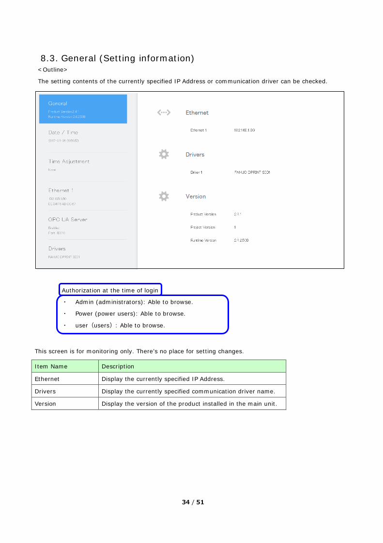
8.3. General (Setting information) <Outline>
The setting contents of the currently specified IP Address or communication driver can be checked.
Authorization at the time of login
・ Admin (administrators): Able to browse.
・ Power (power users): Able to browse.
・ user(users): Able to browse.
This screen is for monitoring only. There’s no place for setting changes.
Item Name Description
Ethernet Display the currently specified IP Address.
Drivers Display the currently specified communication driver name.
Version Display the version of the product installed in the main unit.
35 / 51
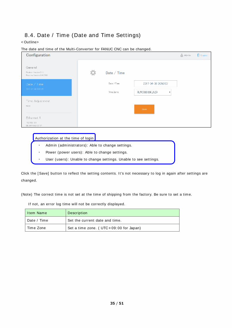
8.4. Date / Time (Date and Time Settings) <Outline>
The date and time of the Multi-Converter for FANUC CNC can be changed.
Authorization at the time of login
・ Admin (administrators): Able to change settings.
・ Power (power users): Able to change settings.
・ User (users): Unable to change settings. Unable to see settings.
Click the [Save] button to reflect the setting contents. It’s not necessary to log in again after settings are
changed.
(Note) The correct time is not set at the time of shipping from the factory. Be sure to set a time.
If not, an error log time will not be correctly displayed.
Item Name Description
Date / Time Set the current date and time.
Time Zone Set a time zone. ( UTC+09:00 for Japan)

36 / 51
8.5. Time Adjustment(Time and Summer Time)
<Outline>
Time (Time and Summer Time) of the Multi-Converter for FANUC CNC can be adjusted.
Authorization at the time of login
・ Admin (administrators): Able to change settings.
・ Power (power users): Able to change settings.
・ User (users): Unable to change settings. Unable to see settings.
Click the [Save] button to reflect the setting contents. It’s not necessary to log in again after settings
are changed.
Item Name Description
Type
Choose among [None], [Rule] and [Date] for a method of configuring a period
of the summer time.
・ None: Selected when the Time Adjustment feature is not used.
・ Rule: Able to adjust the start and end of the summer time choosing among
the 1st to the 5th week, a day of the week, and time as you like.
・ Date: Able to adjust the start and end of the summer time choosing among
a calendar of January to December and time.
Add Date(Rule) Set a day when adding the adjustment time is executed. (On the start day of
the summer time).

37 / 51
Add Time Set a time when adding the adjustment time is executed. (At the start time of
the summer time)
Subtract Date(Rule) Set a day when subtracting the adjustment time is executed. (On the end day
of the summer time)
Subtract Time Set a time when subtracting the adjustment time is executed. (At the end time
of the summer time)
Amount of
Time(Minutes)
Time for addition or subtraction to or from the start/end time of the summer
time. (-120 to 120 minutes)
8.6. Ethernet Settings <Outline>
The Ethernet settings of the Multi-Converter for FANUC CNC can be changed.

38 / 51
Authorization at the time of login
・ Admin (administrators): Able to change settings.
・ Power (power users): Able to change settings.
・ User (users): Unable to change settings. Unable to see settings.
Click the [Save and Reboot] button to reflect the setting contents.
Because of reboot, it’s necessary to log in again after settings are changed.
Item Name Description
DHCP
Select ‘Enable’ or ‘Disable’ of automatic acquisition of the IP Address. (The
default is ‘Disable’.)
Enable: DHCP is enabled.
Disable: DHCP is disabled.
(Note) If DHCP is enabled, the IP Address is never known. In that case,
confirm it with the Target Confirmation Tool (IP Address Confirmation Tool).
Mac Address Mac Address is displayed.
IP Address Specify an IP address. (Default=192.168.1.80)
Subnet Mask Specify a subnet mask. (Default=255.255.255.0)
Default Gateway Specify a default gateway.
DNS Select ‘Enable’ or ‘Disable’ of DNS(Domain Name System).
DNS Server Specify a DNSIP address.
Auto Negotiation Select ‘Enable’ or ‘Disable’ of the Auto Negotiation feature.
Speed Select ‘10M’ or ‘100M’ for communication speed of Ethernet.
Duplex Select ‘Half’ or ‘Full’ for a communication type.
39 / 51
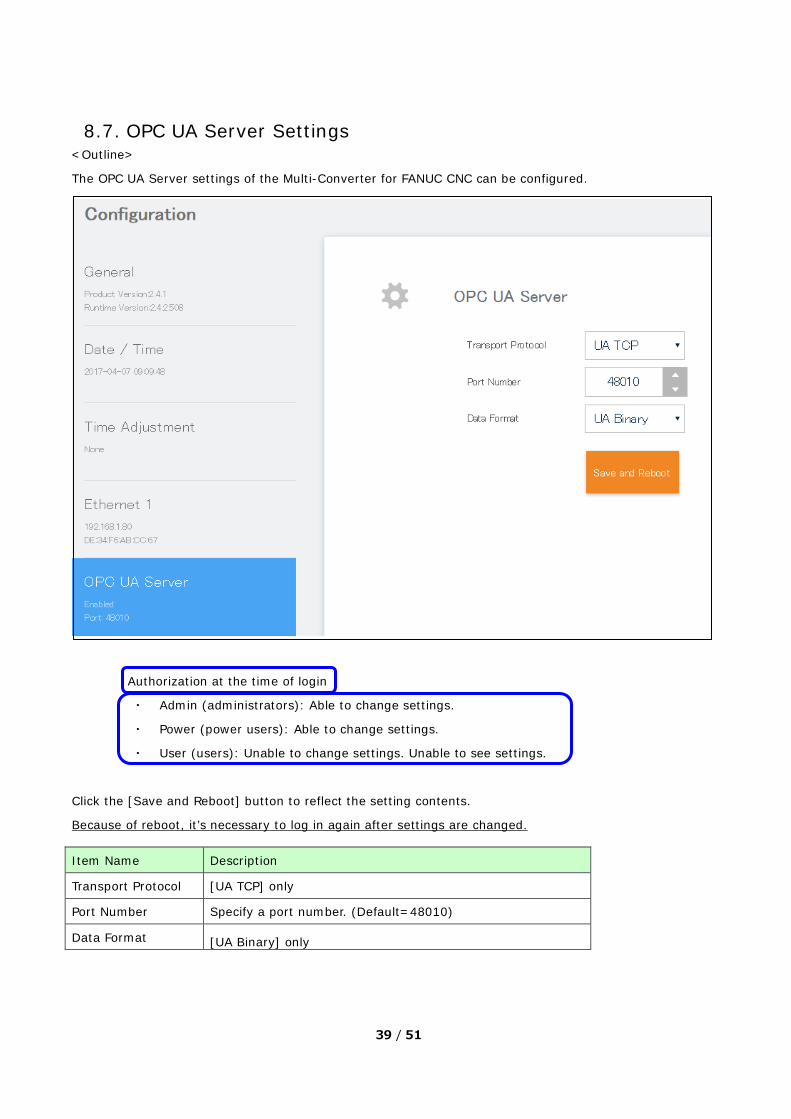
8.7. OPC UA Server Settings <Outline>
The OPC UA Server settings of the Multi-Converter for FANUC CNC can be configured.
Authorization at the time of login
・ Admin (administrators): Able to change settings.
・ Power (power users): Able to change settings.
・ User (users): Unable to change settings. Unable to see settings.
Click the [Save and Reboot] button to reflect the setting contents.
Because of reboot, it’s necessary to log in again after settings are changed.
Item Name Description
Transport Protocol [UA TCP] only
Port Number Specify a port number. (Default=48010)
Data Format [UA Binary] only
40 / 51
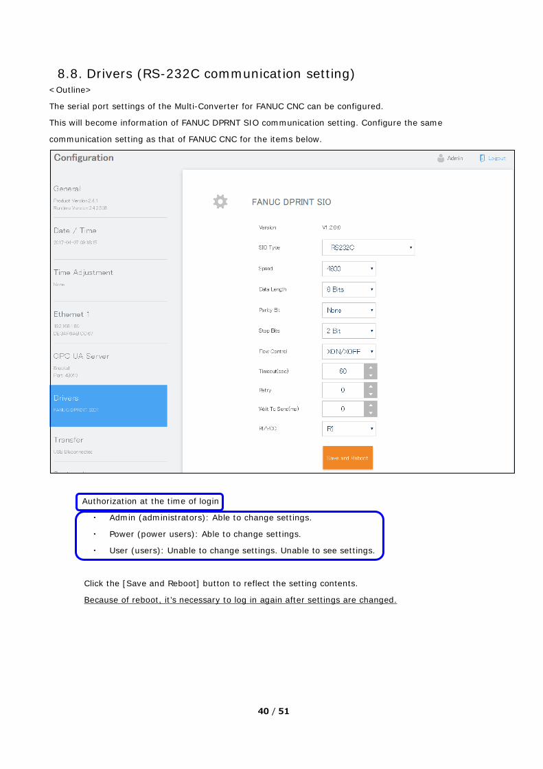
8.8. Drivers (RS-232C communication setting) <Outline>
The serial port settings of the Multi-Converter for FANUC CNC can be configured.
This will become information of FANUC DPRNT SIO communication setting. Configure the same
communication setting as that of FANUC CNC for the items below.
Authorization at the time of login
・ Admin (administrators): Able to change settings.
・ Power (power users): Able to change settings.
・ User (users): Unable to change settings. Unable to see settings.
Click the [Save and Reboot] button to reflect the setting contents.
Because of reboot, it’s necessary to log in again after settings are changed.
41 / 51
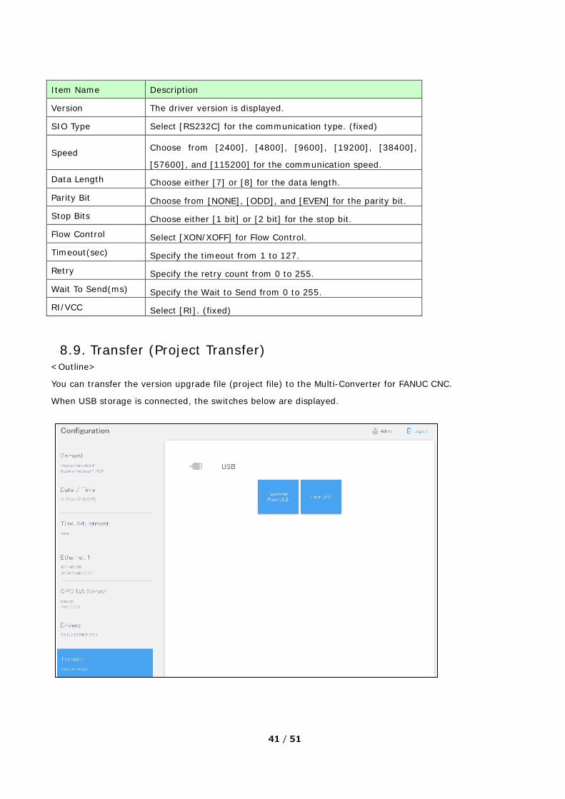
8.9. Transfer (Project Transfer)
<Outline>
You can transfer the version upgrade file (project file) to the Multi-Converter for FANUC CNC.
When USB storage is connected, the switches below are displayed.
Item Name Description
Version The driver version is displayed.
SIO Type Select [RS232C] for the communication type. (fixed)
Speed Choose from [2400], [4800], [9600], [19200], [38400],
[57600], and [115200] for the communication speed. Data Length Choose either [7] or [8] for the data length.
Parity Bit Choose from [NONE], [ODD], and [EVEN] for the parity bit.
Stop Bits Choose either [1 bit] or [2 bit] for the stop bit.
Flow Control Select [XON/XOFF] for Flow Control.
Timeout(sec) Specify the timeout from 1 to 127.
Retry Specify the retry count from 0 to 255.
Wait To Send(ms) Specify the Wait to Send from 0 to 255.
RI/VCC Select [RI]. (fixed)

42 / 51
When a USB storage is not connected, the following message appears.
(Note)
・ Save the version upgrade file (package.BML) to the root directory of USB storage.
・ When transfering the project, User Management data (Security Settings), OPC UA Server Settings, and
Drivers settings are initialized. Back up (Export) the user management data before transferring. (8.13. User Management (Security Settings))
<Update Procedure> 1. Click the Download From USB button.
2. A message is displayed. Confirm the contents and click OK to start transferring.
Once transfer starts, logout from Configuration is done automatically.
3. After transfer is complete, the Multi-Converter for FANUC CNC restarts.
4. Login from the Web browser with the default value (User Name: Admin, Password: Pro-face20).
5. From General (Setting information), confirm the Version has been updated.
6. Import the backed up user management data. (8.13. User Management (Security Settings))
If necessary, set up the OPC UA Server settings and Drivers again.
Item Name Description
Download From USB Transfer the version upgrade file in USB storage to the Multi-Converter for
FANUC CNC. When transfer starts, log out from Configuration.
Eject USB Remove USB storage safely.
43 / 51
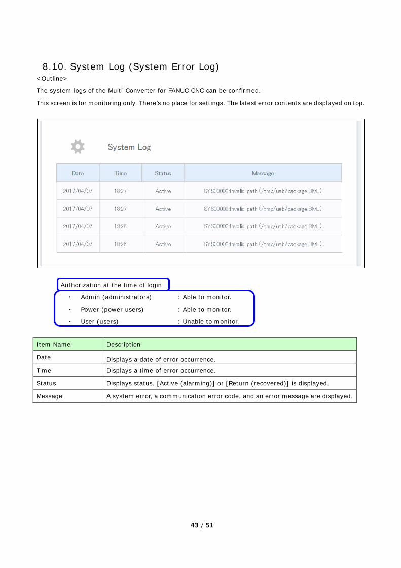
8.10. System Log (System Error Log) <Outline>
The system logs of the Multi-Converter for FANUC CNC can be confirmed.
This screen is for monitoring only. There’s no place for settings. The latest error contents are displayed on top.
Authorization at the time of login
・ Admin (administrators) : Able to monitor.
・ Power (power users) : Able to monitor.
・ User (users) : Unable to monitor.
Item Name Description
Date Displays a date of error occurrence.
Time Displays a time of error occurrence.
Status Displays status. [Active (alarming)] or [Return (recovered)] is displayed.
Message A system error, a communication error code, and an error message are displayed.

44 / 51
8.11. Analog Input <Outline>
This is an analog input screen of the Multi-Converter for FANUC CNC.
Authorization at the time of login
・ Admin (administrators) : Able to change settings and monitor.
・ Power (power users) :Able to change settings and monitor.
・ User (users) : Unable to change settings.
Able to monitor (Another screen is displayed.)
Click the [Save and Reboot] button to reflect the setting contents.
Because of reboot, it’s necessary to log in again after settings are changed.

45 / 51
(Supplementary)
Only when ‘4 to 20mA’ is selected, disconnection of input signals can be detected.
When the analog value is 65535, input signals are disconnected.
When you log in with the User authorization, the following screen appears.
No settings related to analog can be changed.
Item Name Description
Input Data
Displays numerical values of input data. The numerical values change in the
range described below. ・0 to 10V: The data values change in the range of 0 to 8191.
・-10V to 10V: The data values change in the range of -4096 to 4095.
・0 to 20mA: The data values change in the range of 0 to 8191.
・4 to 20mA: The data values change in the range of 0 to 8191.
Data Type Select a data type.
Data Range
Select a data range.
Fixed Value: Fixed setting
User defined: Unable to specify.
Low Pass Filter Choose among [None], [Low], [Standard], and [High] for Low Pass Filter.

46 / 51
8.12. Digital Input <Outline>
Digital inputs of the Multi-Converter for FANUC CNC can be monitored.
ON: Blue, OFF: White
Authorization at the time of login
・ Admin (administrators) : Able to monitor.
・ Power (power users) : Able to monitor.
・ User (users) : Able to monitor.

47 / 51
8.13. User Management (Security Settings)
<Outline>
User management (security) settings of the Multi-Converter for FANUC CNC can be configured.
Authorization at the time of login
・ Admin (administrators) : Able to change settings.
・ Power (power users) : Unable to change settings. Unable to see settings.
・ User (users) : Unable to change settings. Unable to see settings.
(Note) Only the user management data (security data) created on the Multi-Converter for FANUC CNC can
be used.
Item Name Description
Import Transfer user management data (security data) to the Multi-Converter for
FANUC CNC. Enter the key specified at export when transferring the data.
Export
Transfer user management data (security data) from the Multi-Converter for
FANUC CNC to a USB storage.
When exporting the data from the main unit, the key input window appears.
If you have configured the key setting at the time of import, enter the
specified key. If not, just click [OK]. If a key has been entered, it will be
needed at the time of import and using the User Management Tool.
Storage of user management data: [USB root]¥UserManagement¥data.bin

48 / 51
9. Compatibility with the related products ■Version Upgrade File
The file provided at version upgrade is for the Multi-Converter for FANUC CNC only. It cannot be used for other
models.
■User Management Tool (Security Setting)
・ Because user management data (security data) is for the Multi-Converter for FANUC CNC only, it
cannot be used for other models.
・ For user management data (security data), only the file exported from the Multi-Converter for
FANUC CNC unit can be imported.
■USB Storage (storage device)
・ USB1.1 Mass Storage Class compliant
・ The compatible file system is FAT32.
10. Restrictions ・ The day and time is not set at the time of purchase. Be sure to set it.
・ If you transfer data with Transfer (Project Transfer) at the time of version upgrade, the user
management data (security data) will be Initialized. Log in with the default value after transfer is
completed. (User Name: Admin, Password: Pro-face20).
・ Be sure to back up the user management data (security data) before transfer work is done.

49 / 51
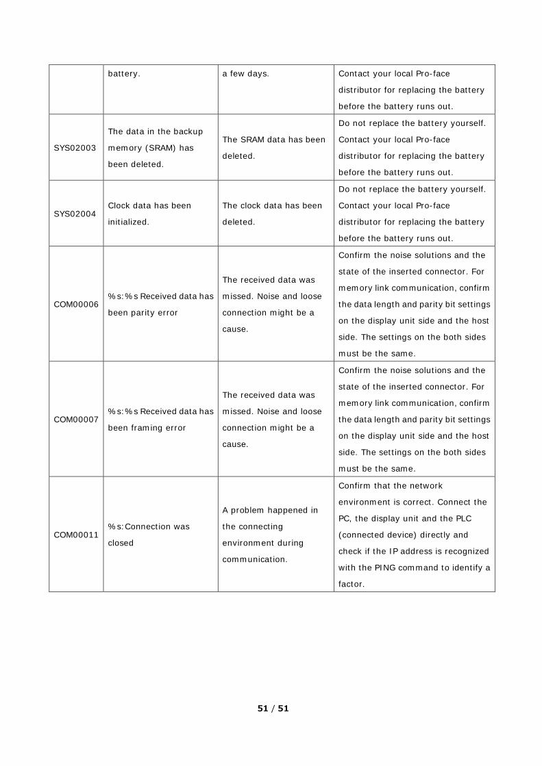
11. Error Code List Error Code Message Cause Solution
APP10507
File open error.
Application cannot open
the file.
There’s no backup file for
Restore.
Perform ‘Restore’ with a backup file
kept.
APP10509 Composition error.
The system configuration
of the connected device is
different from the one at
the time of creating the
backup file.
The system configuration (CPU, Link
I/F, and Communication Type) and
the one of the backup file must be the
same.
APP10511 The equipment is not
connected.
There’s no
communication made
between the display unit
and the connected device.
Turn off the power of the display unit
and then check the cabling and the
connector’s wiring.
APP10512 System configuration is
different.
The model of the
connected device is
different from the one at
the time of creating the
backup file. They must be
the same.
Turn off the power of the display unit
and then check the cabling and the
connector’s wiring.
SYS00001 The volume is write
protected.
The system of the display
unit is in the state of write
inhibit.
1.Cancel the SD card’s lock switch.
2.When using a model in which Write
Filter (write inhibit) can be
configured, cancel the Write Filter.
SYS00002 Invalid path (%s).
The project file saved in
the external storage
cannot be accessed.
Check if the external storage has an
error and then transfer the data
uploaded to the external storage to
the display unit again.
SYS00006
The project designed for
the other product %s
cannot be deployed on
this product %s, during
the %s process.
The model specified in the
project file is different
from the used display
unit.
Change that setting in the project file
to the display unit you are using.

50 / 51
SYS00008
The system version (%s)
is lower than current
system version (%s),
during the %s process.
The runtime version of the
project file in the external
storage is lower than the
one on the display unit.
Follow either one of the instructions
below.
1. Downgrade the runtime version on
the display unit to the same
version as that of the project file.
2. Download the project file with the
same version as the one of the
runtime.
SYS00010
Not enough space (%s)
on this product, during
the %s process. Minimum
space required is %s.
The project file’s data size
is over free space of the
display unit.
Decrease the data size.
SYS00011
Restore of %s from the
backup file failed during
the %s process.
In the process of
transferring the project
file to the display unit
using the external
storage, writing the data
failed.
Restart the display unit and transfer
the data again.
SYS00012
Extraction of %s archive
failed during the %s
process.
In the process of
transferring the project
file to the display unit,
writing the data failed.
Restart the display unit and transfer
the data again.
SYS00014
The upload type (%s) is
not supported in this
version.
Because the runtime
system of the display unit
is old, transfer failed.
Transfer the project file again, and
the runtime will be updated.
SYS00015 %s archive creation failed
during the %s process.
Lack of the free space of
the external storage or
the hard disk. Or it cannot
be accessed.
Confirm that the free space of the
external storage and the hard disk is
enough, the mode is not ‘Read Only’
and you have an access right.
SYS00101
The time variable value is
invalid or has reached the
maximum limit due to the
passage of time. The
variable value is reset
to %s
The clock data of the
display unit has been
initialized.
Check an impact to the features
using the clock data and configure
the clock setting of the display unit
again.
SYS02001 Charge the backup
battery.
The battery will run out in
a few weeks.
Recharge the battery completely for
a few days.
SYS02002 Replace the backup The battery will run out in Do not replace the battery yourself.
51 / 51
battery. a few days. Contact your local Pro-face
distributor for replacing the battery
before the battery runs out.
SYS02003
The data in the backup
memory (SRAM) has
been deleted.
The SRAM data has been
deleted.
Do not replace the battery yourself.
Contact your local Pro-face
distributor for replacing the battery
before the battery runs out.
SYS02004 Clock data has been
initialized.
The clock data has been
deleted.
Do not replace the battery yourself.
Contact your local Pro-face
distributor for replacing the battery
before the battery runs out.
COM00006 %s:%s Received data has
been parity error
The received data was
missed. Noise and loose
connection might be a
cause.
Confirm the noise solutions and the
state of the inserted connector. For
memory link communication, confirm
the data length and parity bit settings
on the display unit side and the host
side. The settings on the both sides
must be the same.
COM00007 %s:%s Received data has
been framing error
The received data was
missed. Noise and loose
connection might be a
cause.
Confirm the noise solutions and the
state of the inserted connector. For
memory link communication, confirm
the data length and parity bit settings
on the display unit side and the host
side. The settings on the both sides
must be the same.
COM00011 %s:Connection was
closed
A problem happened in
the connecting
environment during
communication.
Confirm that the network
environment is correct. Connect the
PC, the display unit and the PLC
(connected device) directly and
check if the IP address is recognized
with the PING command to identify a
factor.


