250
MULTIBLOC 2000 Helical bevel worm geared motors and gear units Technical catalogue Réf. 1023 GB - 2.33 / a - 05.2001
MULTIBLOC 2000Helical bevel worm geared
motors and gear unitsTechnical catalogue
Réf. 1023 GB - 2.33 / a - 05.2001
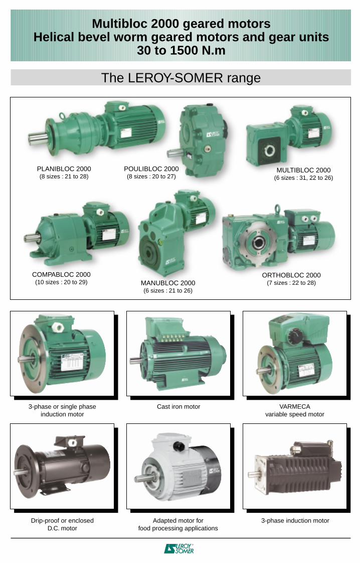
Multibloc 2000 geared motorsHelical bevel worm geared motors and gear units
30 to 1500 N.m
The LEROY-SOMER range
3-phase or single phaseinduction motor
Cast iron motor VARMECAvariable speed motor
Drip-proof or enclosedD.C. motor
3-phase induction motorAdapted motor forfood processing applications
PLANIBLOC 2000(8 sizes : 21 to 28)
COMPABLOC 2000(10 sizes : 20 to 29) MANUBLOC 2000
(6 sizes : 21 to 26)
ORTHOBLOC 2000(7 sizes : 22 to 28)
POULIBLOC 2000(8 sizes : 20 to 27)
MULTIBLOC 2000(6 sizes : 31, 22 to 26)
Multibloc 2000 geared motorsHelical bevel worm geared motors and gear units
30 to 1500 N.m
This document has been translated from the French version (Ref. 1023F) which should be used for reference.LEROY-SOMER reserves the right to modify the design, technical specifications and dimensions of the products shown in this catalogue.
The descriptions cannot in any way be considered contractual.
Pages 101 to 135
Pages 146 to 159
Page 26
Pages 101 to 135
Pages 26 to 32
Pages 26 to 32
Page 214
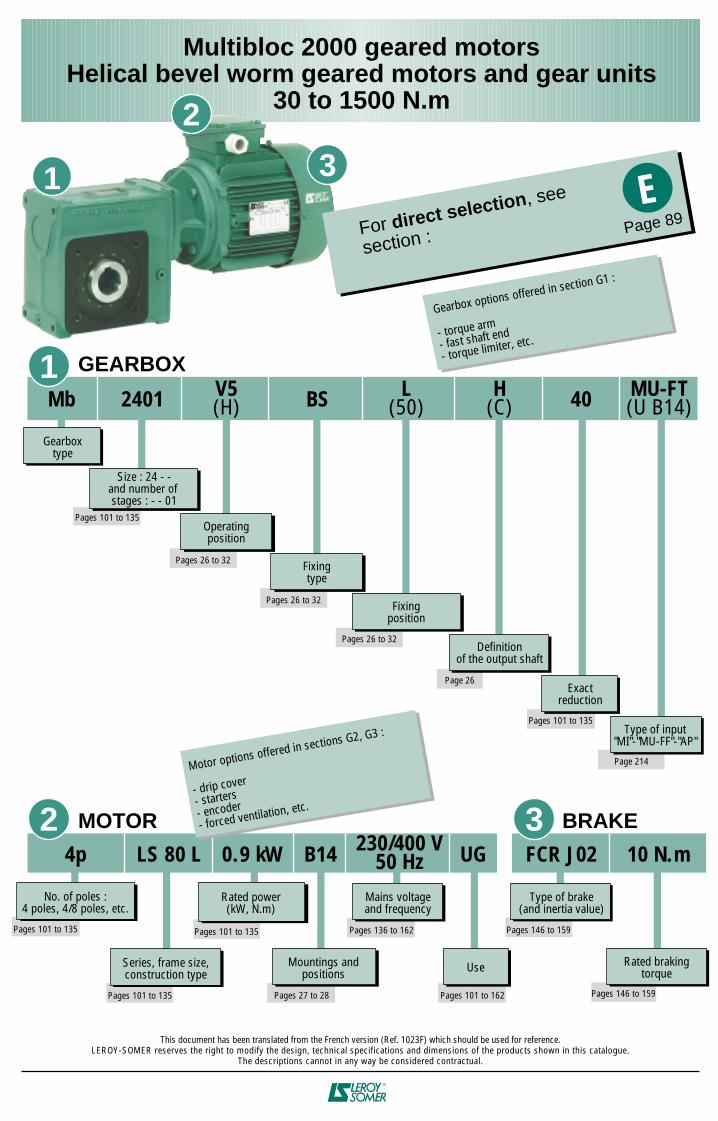
Mb
Gearboxtype
2401 40
Size : 24 - -and number of stages : - - 01
Operatingposition
Pages 26 to 32
Fixingtype
Fixingposition
Definitionof the output shaft
1
Pages 27 to 28
Pages 101 to 135
Pages 146 to 159
Pages 101 to 135
LS 80 L
Series, frame size,construction type
0.9 kW4p B14 UG FCR J02 10 N.m
Rated power(kW, N.m)
No. of poles :4 poles, 4/8 poles, etc.
Mountings andpositions
Pages 101 to 162
Use
Pages 136 to 162
Mains voltageand frequency
Type of brake(and inertia value)
Rated brakingtorque
2 3
GEARBOX
MOTOR BRAKE
Motor options offered in sections G2, G3 :
- drip cover
- starters- encoder
- forced ventilation, etc.
Gearbox options offered in section G1 :
- torque arm
- fast shaft end
- torque limiter, etc.
V5(H) BS
230/400 V50 Hz
L(50)
MU-FT(U B14)
H(C)
Pages 101 to 135
Exactreduction
Type of input"MI"-"MU-FF"-"AP"
For direct selection, see
section :
EPage 89
1
2
3
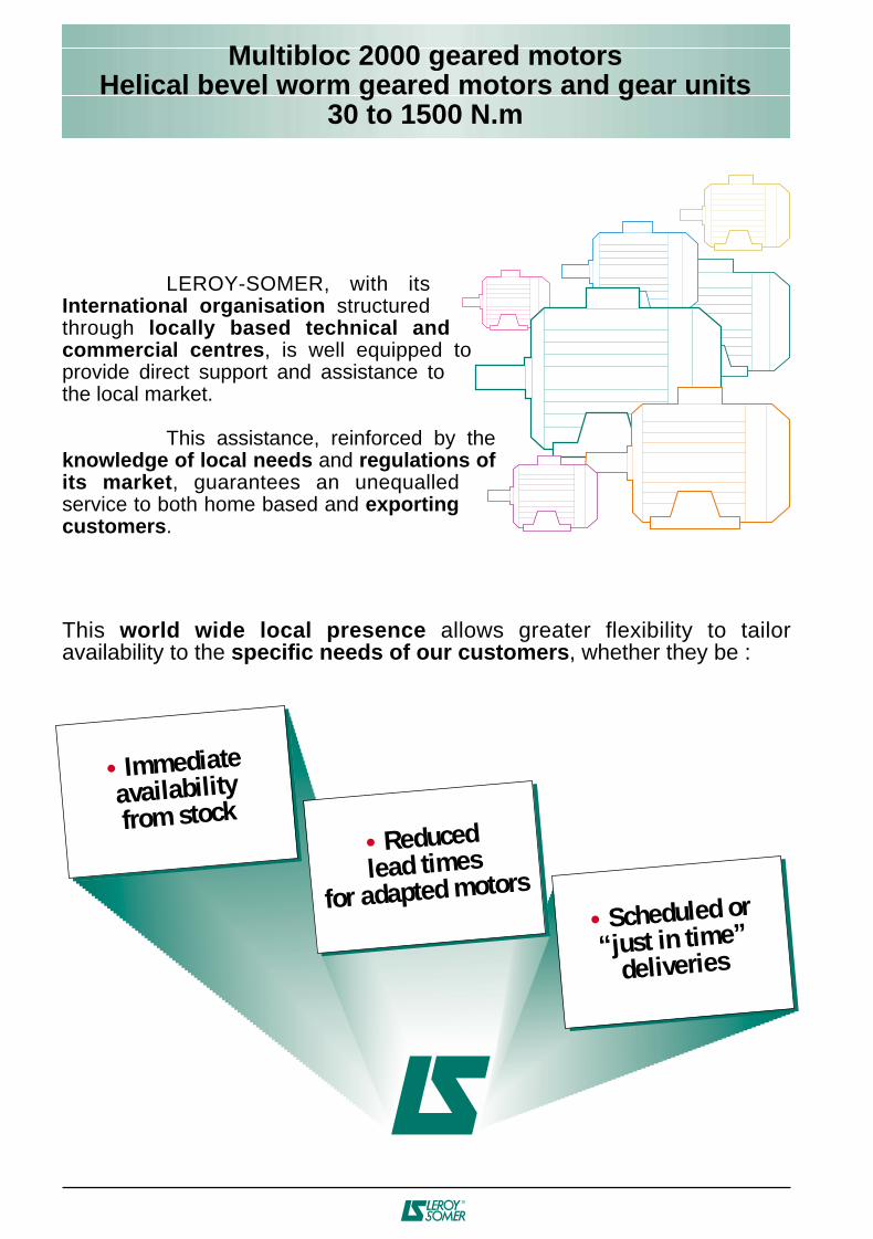
This world wide local presence allows greater flexibility to tailor availability to the specific needs of our customers, whether they be :
LEROY-SOMER, with its International organisation structured through locally based technical and commercial centres, is well equipped to provide direct support and assistance to the local market.
This assistance, reinforced by the knowledge of local needs and regulations of its market, guarantees an unequalled service to both home based and exporting customers.
• Immediateavailabilityfrom stock
• Reducedlead times
for adapted motors• Scheduled or“just in time”
deliveries
Multibloc 2000 geared motorsHelical bevel worm geared motors and gear units
30 to 1500 N.m
Multibloc 2000 geared motorsHelical bevel worm geared motors and gear units
30 to 1500 N.m
ELECTRO-MECHANICALASSEMBLIES
PERPENDI-CULAR
AXIAL
SHAFT
BASEPLATEor
FLANGE
VERYHIGH
WORMGEAR
GEAREDMOTOR(direct)
PARALLELGEARS TAPER
BUSH
100 to4500 N.m
5 to55 N.m
1 to30 N.m
30 to1500 N.m
ORTHOBLOC2000
MULTIBLOC2000
MULTIBLOC2100
MINIBLOC
MANUBLOC2000
BELT ANDPULLEY
PARALLELGEARS
HOLLOW SHAFTTAPERBUSH
100 to13,000 N.m
POULIBLOC2000
200 to10,000 N.m
SOLID SHAFTHOLLOW SHAFT
HELICALBEVEL andPARALLEL
GEARS
ROTATING
GEARBOX
LINEAR
CYLINDER BUILT-INMOTOR VERELEC
TYPEOF
MOVEMENT
REVERSIBILITY
MOUNTING
STRONG PLANETARYGEARS
NORMAL PARALLELGEARS
150 to70,000 N.m
PLANIBLOC2000
SOLID SHAFT60 to16,000 N.m
COMPABLOC2000
SOLID SHAFT15 to65 N.m
COMPABLOC1000
MOMENTARYOVERLOADS
OUTPUT
BASEPLATEor
FLANGE
LOW
SOLID SHAFTHOLLOW SHAFT
SOLID SHAFTHOLLOW SHAFT
SOLID SHAFTHOLLOW SHAFT
SOLID SHAFTHOLLOW SHAFT
SOLID SHAFTHOLLOW SHAFT
DRIVE
TORQUE
TORQUE
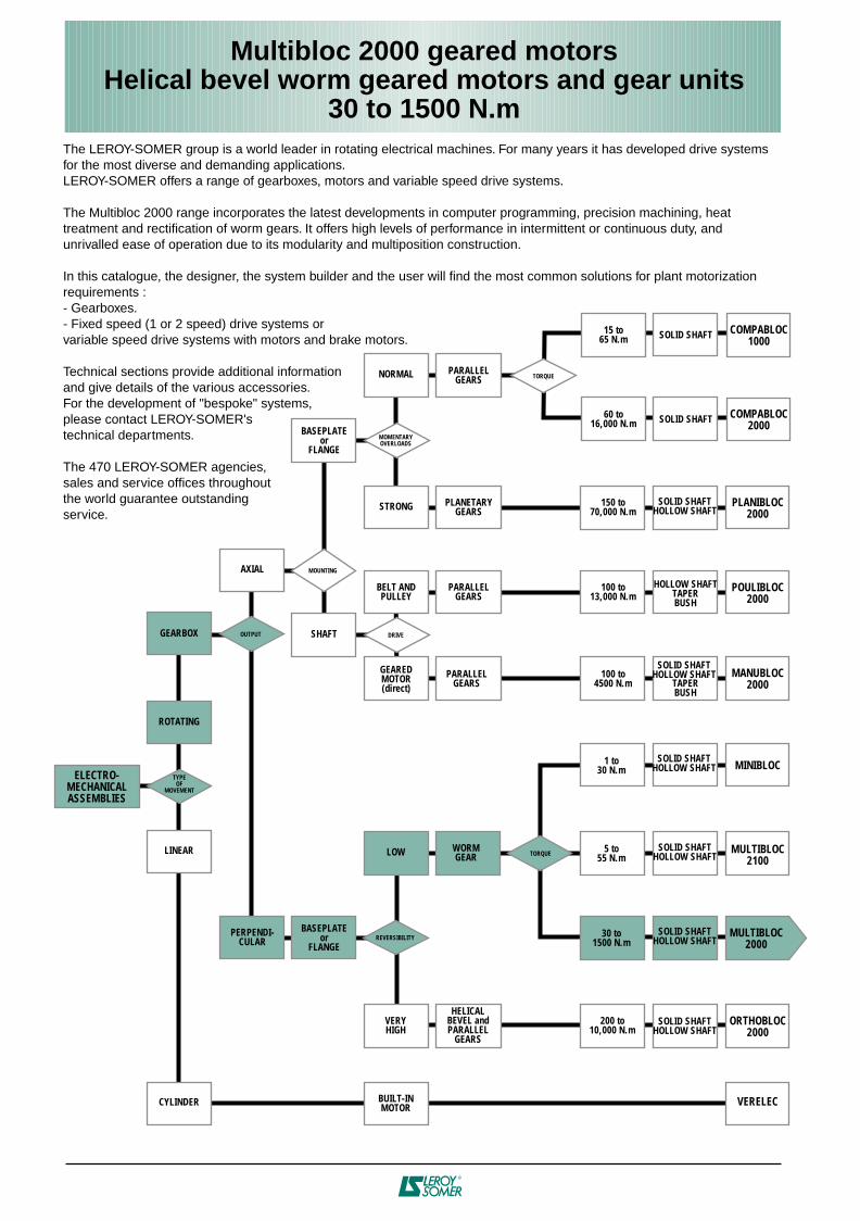
The LEROY-SOMER group is a world leader in rotating electrical machines. For many years it has developed drive systemsfor the most diverse and demanding applications.LEROY-SOMER offers a range of gearboxes, motors and variable speed drive systems.
The Multibloc 2000 range incorporates the latest developments in computer programming, precision machining, heat treatment and rectification of worm gears. It offers high levels of performance in intermittent or continuous duty, andunrivalled ease of operation due to its modularity and multiposition construction.
In this catalogue, the designer, the system builder and the user will find the most common solutions for plant motorizationrequirements :- Gearboxes.- Fixed speed (1 or 2 speed) drive systems orvariable speed drive systems with motors and brake motors.
Technical sections provide additional informationand give details of the various accessories.For the development of "bespoke" systems, please contact LEROY-SOMER'stechnical departments.
The 470 LEROY-SOMER agencies,sales and service offices throughoutthe world guarantee outstandingservice.
PAGES
4
C1.1 - Components, worm gear ............................................. 25
C1.2 - Mounting arrangements .............................................. 26
C1.3 - Operating positions and forms .................................. 27-32
C2 - Applications 33
C2.1 - General ............................................................................ 33
C2.1.1 - Mains connection .......................................... 33
C2.1.2 - Terminal box and cable gland .................... 35
C2.1.3 - Terminal blocks ............................................. 35
C2.1.4 - Earth terminal ................................................ 35
C2.1.5 - Motors wiring diagrams ................................ 35
C2.1.6 - Motor connections ........................................ 36-38
C2.1.7 - Brake motor connection diagrams .............39-47
C2.2 - Fixed speed motors ...................................................... 48
C2.2.1 - Components of non brake motors.............. 48
C2.2.2 - Types of bearings and standard fitting
arrangements.................................................................. 49
C2.2.3 - Brake motor selection guide ....................... 50
C2.2.4 - Components of brake motors ..................... 51-54
C2.2.5 - Types of bearings for brake motors .......... 55
C2.3 - Variable speed motors ................................................. 56
C2.3.1 - Selection guide : motors and speed controllers 56-58
C2.3.2 - Motor components ........................................ 59
C2.3.3 - Brake operation ............................................. 60
D - OPERATION ................................................................... 61
D1 - Gearbox 62
D1.1 - Definition of the duty factor required for the
application ...................................................................... 62
D1.1.1 - Determining duty factor K1 ......................... 62
D1.1.2 - Determining duty factor K2 ......................... 63
D1.2 - Maximum permissible torque ...................................... 63
D1.3 - Thermal power ............................................................... 64
D1.4 - Radial load ...................................................................... 65
D1.4.1 - Radial force on input shaft .......................... 65
D1.4.2 - Radial force on output shaft ........................65-66
D1.4.3 - Radial force on standard left or
right output shaft ............................................ 67
D1.4.4 - Radial force on standard output shaft
with flange ....................................................... 68
D1.5 - Axial load ......................................................................... 69
D1.5.1 - Axial force on output shaft -
Multibloc 3101 - 2201 ................................... 70
D1.5.2 - Axial force on output shaft -
Multibloc 2301 - 2401 ................................... 71
D1.5.3 - Axial force on output shaft -
Multibloc 2501 - 2601 ................................... 72
D1.6 - Efficiency and reversibility ........................................... 73
D1.6.1 - Angular play on the output shaft ................ 73
D1.6.2 - Efficiency ........................................................ 73
D1.6.3 - Reversibility..................................................... 73
D1.6.4 - Running-in the gearbox................................ 73
A - GENERAL INFORMATION ................................ 7
A1 - Quality Assurance 7
A2 - Units of measurement and standard formulae 8
A2.1 - Electricity and electromagnetism ............................... 8
A2.2 - Thermodynamics ........................................................... 9
A2.3 - Noise and vibration ....................................................... 9
A2.4 - Dimensions ..................................................................... 9
A2.5 - Mechanics ....................................................................... 10
A3 - Unit conversions 11
A3.1 - Glossary .......................................................................... 11
A4 - Standard formulae used in electrical engineering 12
A4.1 - Mechanical formulae ..................................................... 12
A4.2 - Electrical formulae ......................................................... 13
A4.3 - Formulae for operating in S4 type duty ..................... 14
B - ENVIRONMENT ........................................................... 15-16
B1 - Definition of indices of protection 17
B2 - Environmental limitations 18
B2.1 - Normal operating conditions ....................................... 18
B2.2 - Correction according to altitude
and ambient temperature ............................................ 18
B2.3 - Relative and absolute humidity ................................... 18
B2.4 - Drain holes ...................................................................... 19
B2.5 - Drip covers ...................................................................... 19
B3 - Impregnation and enhanced protection 20
B3.1 - Normal atmospheric pressure ..................................... 20
B3.2 - Influence of atmospheric pressure ............................. 21
B4 - Heaters 22
B4.1 - Space heaters ................................................................ 22
B4.2 - D.C. injection .................................................................. 22
B4.3 - A.C. injection.................................................................... 22
B5 - External finish 23
B5.1 - Preparation of surfaces ................................................ 23
B5.2 - Definition of atmospheres ............................................ 23
B5.3 - Painting systems ........................................................... 23
B6 - Interference suppression 24
C - CONSTRUCTION ....................................................... 25
C1 - Gearbox 25
PAGES
Multibloc 2000 geared motorsContents
5
PAGES PAGES
G1.1 - Torque arm "R" .............................................................. 210
G1.2 - Output flange BT on Mb 26-- ...................................... 210
G1.3 - Fast shaft end ................................................................ 211
G1.4 - "Customised" solid output shaft ................................. 211
G1.5 - Torque limiter "LC" ........................................................212-213
G1.6 - Motor / gearbox mounting arrangements ................. 214
G2 - Applications - Fixed speed 215
G2.1 - Starters ............................................................................215-216
G2.2 - Drip cover ....................................................................... 217
G2.3 - Brake release systems ................................................. 218
G2.3.1 - Automatic return lever .................................. 218
G2.3.2 - Manual release with automatic return ....... 219
G2.3.3 - Simple release ............................................... 219
G2.4 - Shaft exiting on brake side .......................................... 220
G2.4.1 - Crankshaft socket type ................................ 220
G2.4.2 - Cylindrical keyed shaft type ........................ 221
G2.5 - Compatibility of brake options..................................... 222
G3 - Applications - Variable speed 223
G3.1 - Incremental encoder ..................................................... 223
G3.2 - Forced ventilation........................................................... 224
G3.3 - Parking brake ................................................................. 224
G3.4 - Connection diagrams for the LSMV motor
options ............................................................................ 225
H - MAINTENANCE - INSTALLATION ............ 226
H1 - Storage - Commissioning - Lubrication 226
H1.1 - Storage .......................................................................... 226
H1.2 - Commissioning .............................................................. 226
H1.3 - Lubrication and Maintenance ...................................... 226
H2 - Mounting recommendations 227
H2.1 - Fixing the gearbox ......................................................... 227
H2.2 - Mounting the torque arm .............................................. 227
H2.3 - Installing the geared motor .......................................... 228
H3 - Identification 229
H3.1 - Nameplates .................................................................... 229
H3.1.1 - Gearboxes ...................................................... 229
H3.1.2 - Induction motors ............................................ 230
H3.1.3 - Variable speed motors ................................. 231
H3.1.4 - Brake motors ..................................................232-235
H3.2 - Exploded views - Parts list .......................................... 236
H3.2.1 - Gearbox ...........................................................236-237
H3.2.2 - Induction motors ............................................ 238
H3.2.3 - Brake motors ..................................................239-243
H4 - Weight and dimensions of packaging 244
D2 - Applications 74
D2.1 - Definition of duty types ................................................. 74
D2.1.1 - Motors ..............................................................74-78
D2.1.2 - Brake motors ..................................................79-80
D2.2 - Supply voltage ............................................................... 81
D2.2.1 - Regulations and standards ......................... 81-82
D2.2.2 - Effects on motor performance..................... 83
D2.3 - Insulation class - Temperature rise and
thermal reserve ............................................................. 84
D2.4 - Machine vibration levels .............................................. 85-86
D2.5 - Thermal protection......................................................... 87
E - CHARACTERISTICS ............................................... 89
E1 - Selection of gearbox with "AP" input shaft 89
E1.1 - Method .......................................................................... 90
E1.2 - Example and gearbox description .............................. 91
E1.3 - Selection tables .............................................................. 92
E1.3.1 - Input speed : 2850 min-1 .............................. 92
E1.3.2 - Input speed : 1430 min-1 .............................. 93
E1.3.3 - Input speed : 950 min-1 ................................ 94
E1.3.4 - Input speed : 715 min-1 ................................ 95
E2 - Selection of geared motors 96
E2.1 - Method .......................................................................... 96
E2.2 - Example and geared motor description .................... 97
E2.3 - Quick selection using AGMA ....................................... 98-100
E2.4 - Tables of mechanical characteristics............................. 101-137
E2.5 - Tables of electrical characteristics ..................................138-164
E2.5.1 - Fixed speed no brake ................................... 138-145
E2.5.2 - Fixed speed with brake ................................ 146-162
E2.5.3 - Variable speed no brake .............................. 163
E2.5.4 - Variable speed with brake ........................... 164
F - DIMENSIONS ................................................................. 165
F1 - Gearboxes and geared motors 166
F1.1 - Dimensions of protective cover .................................. 166
F1.2 - Output shaft and details of gearbox form ................ 167
F1.3 - Dimensions and weight of "AP" gearboxes ............. 168-175
F1.4 - Dimensions and weight of geared motors, 1 stage ...... 176-191
F1.5 - Dimensions and weight of geared motors, 2 and 3 stages.... 192-207
F2 - Variable speed applications 208
F2.1 - Dimensions of LSMV motors and options ................ 208-209
G - FEATURES ...................................................................... 210
G1 - Gearbox 210
Multibloc 2000 geared motorsContents
Copyright 2001 : MOTEURS LEROY-SOMER
AFAQ 7Altitude 18Ambient temperature 18Angular play 73"AP" input shaft 90Axial force 69
Balancing 85Bearings 66Brakes 50
Cable glands 34CE 24Characteristics 90-135Combined mounting 32Commissioning 226Connection 33Connection diagrams 35 to 47Construction 25Coupling 36"Customised" solid shaft output 211
Digistart 215Dimensions 9Dimensions and weight - "AP" gearboxes 168Dimensions and weight of geared motors 176Direction of rotation 35Drain holes 19Drip covers 19-217Duty types 79-80
Earth terminals 35Efficiency 73Electrical characteristics 136-164Electrical formulae 13Electricity 8Electromagnetism 8Encoder 223Environment 20Exploded views 236 to 243
FAP2 - FAP 54FAST 53Fast shaft end 211FCO 52FCR 51Features 210-211Fixed speed options 215Fixing 227FMV 57Forms 27 to 29Frequency controller 57
Gearbox 3-25Gearbox options 210Gearbox thermodynamics 9-64Glossary 11
Heating 22, 84Humidity 18Hypersynchronous 216
Identification 229Impregnation 20Induction brake motors 50
Induction motors 48Inertia 62Installation 226, 228Insulation class 84Interference suppression 24ISO 9001 7
K1 duty factor 62K2 duty factor 63
"LC" torque limiter 212Lubrication 223
Maintenance 226Maximum permissible torque 63Mechanical formulae 12Mechanics 10Mounting 228Mounting motors on gearboxes 214Movement 10Multi-speed motors 144-160
Nameplates 229 to 235Noise 9
Oil 226Operating positions 27 to 32Operating forms and positions 28Output shaft 167
Packaging 244Painting 23Parking brake 224Parts list 236Possible forms and shafts 26Protection indices 17
Quality 7
"R" torque arm 210Radial force 65Reinforced protection 20Reversibility 73
Selection tables 101 to 135Shafts 27Single speed motors 136 to 143Starters 215Storage 266Supply voltage 81
Terminal blocks 35Terminal box 33Thermal power 64Thermal protection 87Thermal reserve 84Two-speed motors 144
UMV 57Unistart 215Unit conversions 11Units and standard formulae 8
Variable speed 56Variable speed options 223Vibrations 9-85
6
PAGES PAGES
Multibloc 2000 geared motorsIndex
A
7
A1 - Quality assurance
Multibloc 2000 geared motorsGeneral information
At LEROY-SOMER, we think it vital forour customers to know the importancewe attach to quality.
Industrial concerns are having to copewith an ever more competitiveenvironment. Productivity depends to aconsiderable degree on the rightinvestment at the right time. LEROY-SOMER has the answer,building motors to precise standards ofquality.
When carrying out quality checks on amachine's performance, the first step isto measure the level of customersatisfaction.
Careful study of this information tellsus which points need looking at,improving and monitoring.
From the moment you place your orderwith our administrative staff until themotor is up and running (after designstudies, launch and productionactivities) we keep you informed andinvolved.
Our own procedures are constantlyunder review, using both "hoshin" pro-duction improvement programmes andimproved engineering techniques.All our staff are involved in both opera-tional process analysis and continuoustraining programmes. These initiativeshelp them serve you better, and in-creased skills bring increased motivation.
LEROY-SOMER has entrusted thecertification of its expertise to variousinternational organizations.Certification is granted by indepen-dent professional auditors, and rec-ognises the high standards of thecompany's quality assurance pro-cedures.All activities resulting in the final ver-sion of the machine have thereforereceived official ISO 9001 accre-ditation. Products are alsoapproved by official bo-dies who inspect theirtechnical performancewith regard to the var-ious standards.This is a fundamentalrequirement for a com-pany of internationalstanding.
8
AQuantity Units
Units and expressionsnot recommended
English name French name Symbol Definition SINon SI,but accepted Conversion
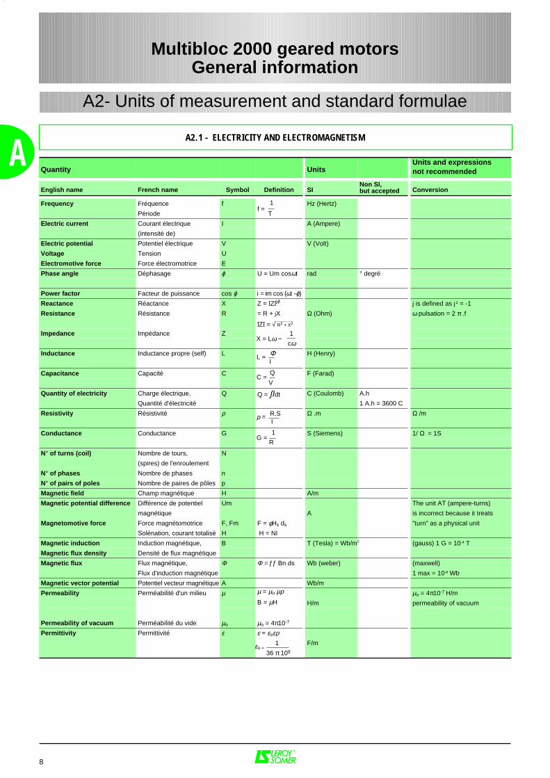
Frequency Fréquence f 1 Hz (Hertz)
Période T
Electric current Courant électrique I A (Ampere)
(intensité de)
Electric potential Potentiel électrique V V (Volt)
Voltage Tension U
Electromotive force Force électromotrice E
Phase angle Déphasage ϕ U = Um cosωt rad ° degré
Power factor Facteur de puissance cos ϕ i = im cos (ωt -ϕ)
Reactance Réactance X Z = IZIjϕ j is defined as j 2 = -1
Resistance Résistance R = R + jX Ω (Ohm) ω pulsation = 2 π .f
IZI = √ R2 + X2
Impedance Impédance Z 1
cωInductance Inductance propre (self) L Φ H (Henry)
Capacitance Capacité C Q F (Farad)
Quantity of electricity Charge électrique, Q Q = ∫Ιdt C (Coulomb) A.h
Quantité d'électricité 1 A.h = 3600 C
Resistivity Résistivité ρ R.S Ω .m Ω /m
Conductance Conductance G 1 S (Siemens) 1/ Ω = 1S
N° of turns (coil) Nombre de tours, N
(spires) de l'enroulement
N° of phases Nombre de phases n
N° of pairs of poles Nombre de paires de pôles p
Magnetic field Champ magnétique H A/m
Magnetic potential difference Différence de potentiel Um The unit AT (ampere-turns)
magnétique A is incorrect because it treats
Magnetomotive force Force magnétomotrice F, Fm F = φHs ds "turn" as a physical unit
Solénation, courant totalisé H H = NI
Magnetic induction Induction magnétique, B T (Tesla) = Wb/m2 (gauss) 1 G = 10-4 T
Magnetic flux density Densité de flux magnétique
Magnetic flux Flux magnétique, Φ Φ = ƒƒ Bn ds Wb (weber) (maxwell)
Flux d'induction magnétique 1 max = 10-8 Wb
Magnetic vector potential Potentiel vecteur magnétique A Wb/m
Permeability Perméabilité d'un milieu µ µ = µo µρ µo = 4π10-7 H/mB = µH H/m permeability of vacuum
Permeability of vacuum Perméabilité du vide µo µo = 4π10-7
Permittivity Permittivité ε ε = εoερ 1 F/m
36 π 109
X = Lω −
L = I
C = V
ρ = I
G = R
f =
εo =
A2.1 - ELECTRICITY AND ELECTROMAGNETISM
Multibloc 2000 geared motorsGeneral information
A2- Units of measurement and standard formulae
Quantity UnitsUnits and expressionsnot recommended
English name French name Symbol Definition SINon SI,but accepted Conversion
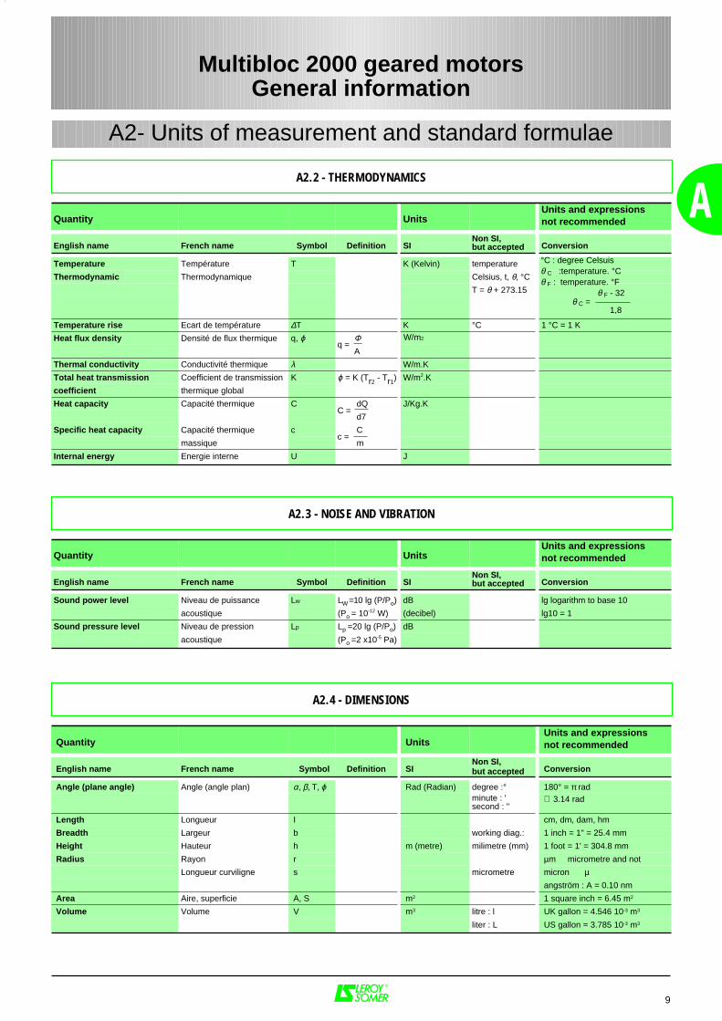
Temperature Température T K (Kelvin) temperature
Thermodynamic Thermodynamique Celsius, t, θ, °CT = θ + 273.15
1,8
Temperature rise Ecart de température ∆T K °C 1 °C = 1 K
Heat flux density Densité de flux thermique q, ϕ Φ A
Thermal conductivity Conductivité thermique λ W/m.K
Total heat transmission Coefficient de transmission K ϕ = K (Tr2 - Tr1
) W/m2.K
coefficient thermique global
Heat capacity Capacité thermique C dQ J/Kg.K
d7
Specific heat capacity Capacité thermique c C
massique m
Internal energy Energie interne U J
9
A
q =W/m2
C =
c =
Quantity UnitsUnits and expressionsnot recommended
English name French name Symbol Definition SINon SI,but accepted Conversion
Sound power level Niveau de puissance Lw LW =10 lg (P/Po) dB lg logarithm to base 10
acoustique (Po = 10-12 W) (decibel) lg10 = 1
Sound pressure level Niveau de pression Lp Lp =20 lg (P/Po) dB
acoustique (Po =2 x10⁻⁵ Pa)
°C : degree Celsuisθ C :temperature. °C θ F : temperature. °F θ F - 32
θ C =
A2.2 - THERMODYNAMICS
A2.3 - NOISE AND VIBRATION
A2.4 - DIMENSIONS
A2- Units of measurement and standard formulae
Multibloc 2000 geared motorsGeneral information
Quantity UnitsUnits and expressionsnot recommended
English name French name Symbol Definition SINon SI,but accepted Conversion
Angle (plane angle) Angle (angle plan) α, β, T, ϕ Rad (Radian) degree :° 180° = π radminute : 'second : "
≅ 3.14 rad
Length Longueur I cm, dm, dam, hm
Breadth Largeur b working diag.: 1 inch = 1" = 25.4 mm
Height Hauteur h m (metre) milimetre (mm) 1 foot = 1' = 304.8 mm
Radius Rayon r µm micrometre and not
Longueur curviligne s micrometre micron µangström : A = 0.10 nm
Area Aire, superficie A, S m2 1 square inch = 6.45 m2
Volume Volume V m3 litre : l UK gallon = 4.546 10-3 m3
liter : L US gallon = 3.785 10-3 m3
A2- Units of measurement and standard formulae
10
A Quantity UnitsUnits and expressionsnot recommended
English name French name Symbol Definition SINon SI,but accepted Conversion
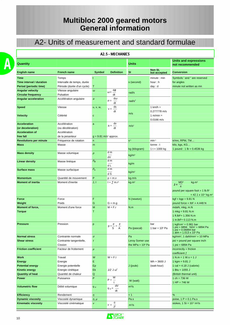
Time Temps t minute : min Symbols ' and " are reserved
Time interval / duration Intervalle de temps, durée s (second) hour : h for angles
Period (periodic time) Période (durée d'un cycle) T day : d minute not written as mn
Angular velocity Vitesse angulaire ω dϕ
Circular frequency Pulsation dt
Angular acceleration Accélération angulaire α dω
dt
Speed Vitesse u, v, w, ds 1 km/h =
dt 0.277778 m/s
Velocity Célérité c 1 m/min =
0.0166 m/s
Acceleration Accélération a dv
(or deceleration) (ou décélération) dt
Acceleration of Accélération
free fall de la pesanteur g = 9.81 m/s2 approx.
Revolutions per minute Fréquence de rotation n s-1 min-1 tr/mn, RPM, TM…
Mass Masse m tonne : t kilo, kgs, KG…
kg (kilogram) 1 t = 1000 kg 1 pound : 1 lb = 0.4536 kg
Mass density Masse volumique ρ d m
dV
Linear density Masse linéique ρe d m
d L
Surface mass Masse surfacique ρA d m
d S
Momentum Quantité de mouvement P p = m.v kg.m/s
Moment of inertia Moment d'inertie J, I I = ∑ m.r2 kg.m2 MD2 kg.m2
4pound per square foot = 1 lb.ft2
= 42.1 x 10⁻³ kg.m2
Force Force F N (newton) kgf = kgp = 9.81 N
Weight Poids G G = m.g pound force = IbF = 4.448 N
Moment of force, Moment d'une force M M = F.r N.m mdaN, mkg, m.N
Torque T 1 mkg = 9.81 N.m
1 ft.lbF= 1.356 N.m
1 in.lbF= 0.113 N.m
Pressure Pression p F F bar
S A Pa (pascal) 1 bar = 105 Pa
Normal stress Contrainte normale σ Pa kg/mm2, 1 daN/mm2 = 10 MPa
Shear stress Contrainte tangentielle, τ Leroy Somer use psi = pound per square inch
Cission the MPa = 106 Pa 1 psi = 6894 Pa
Friction coefficient Facteur de frottement µ incorrectly = friction
coefficient ƒ
Work Travail W W = F.I 1 N.m = 1 W.s = 1 J
Energy Energie E Wh = 3600 J 1 kgm = 9.81 J
Potential energy Energie potentielle Ep J (joule) (watt-hour) 1 cal = 4.18 J (calorie)
Kinetic energy Energie cinétique Ek 1/2 J ω2 1 Btu = 1055 J
Quantity of heat Quantité de chaleur Q (British thermal unit)
Power Puissance P W 1 ch = 736 W
t 1 HP = 746 W
Volumetric flow Débit volumique q v dV m3/s
dt
Efficiency Rendement η < 1 %
Dynamic viscosity Viscosité dynamique η, µ Pa.s poise, 1 P = 0.1 Pa.s
Kinematic viscosity Viscosité cinématique ν η stokes, 1 St = 10-4 m2/s ρ
ω = rad/s
rad/s2α =
m/s
v =
a = m/s2
kg/m3
kg/m
J =
kg/m2
W (watt)P =
q v =
m2/sν =
1 kgf/cm2 = 0.981 bar1 psi = 6894 N/m2 = 6894 Pa1 psi = 0.06894 bar1 atm = 1.013 x 10⁵ Pa
p = =
A2.5 - MECHANICS
Multibloc 2000 geared motorsGeneral information

11
AUnits MKSA (IS International system) AGMA (US system)
Length 1 m = 3.2808 ft 1 mm = 0.03937 in 1 ft = 0.3048 m 1 in = 25.4 mm
Weight 1 kg = 2.2046 lb 1 lb = 0.4536 kg
Torque 1 Nm = 0.7376 lb.ft 1 N.m = 141.6 oz.in 1 lb.ft = 1.356 N.m 1 oz.in = 0.00706 N.m
Force 1 N = 0.2248 lb 1 lb = 4.448 N
Moment of inertia 1 kg.m2 = 23.73 lb.ft2 1 lb.ft2 = 0.04214 kg.m2
Power 1 kW = 1.341 HP 1 HP = 0.746 kW
Pressure 1 kPa = 0.14505 psi 1 psi = 6.894 kPa
Magnetic flux 1 T = 1 Wb / m2 = 6.452104 line / in2 1 line / in2 = 1.55010-5 Wb / m2
Magnetic losses 1 W / kg = 0.4536 W / lb 1 W / lb = 2.204 W / kg
Symbol Definition Symbol Definition
d/h starts per hour M torque transmitted by the geared motorN.m
h/j daily operating timein hours per day MMax
maximum permissible torqueN.m
FJ inertia factor MSoutput selection torque
N.m
FM operating factor expressed as a % MuStorque required for the application during output
N.m
i exact reduction of gearbox MnSrated output torque
N.m
iu reduction available to the application nSrotational speed of gearbox
min-1
JC/Mmoment of inertia of the load
applied to the motor shaft expressed in kg.m2 nuEuseful input rotational speed of gearbox
min-1
JMmoment of inertia of the motor
expressed in kg.m2 nuSuseful output rotational speed of gearbox
min-1
K overall duty factor P standard motor powerkW
K1 duty factordependent upon the inertia Pn
rated powerkW
K2 duty factordependent upon the operating factor PuE
input power required for the applicationkW
KPmaximum possible duty factor
for the geared motor PuSoutput power required for the application
kW
Kθθθθthermal power
correction factor Ptrated thermal power of gearbox
kW
θθθθ ambient temperature°C
Z (d/h) starting frequencyof the application (d/h)
A3.1 - GLOSSARY
A3 - Unit conversions
Multibloc 2000 geared motorsGeneral information
12
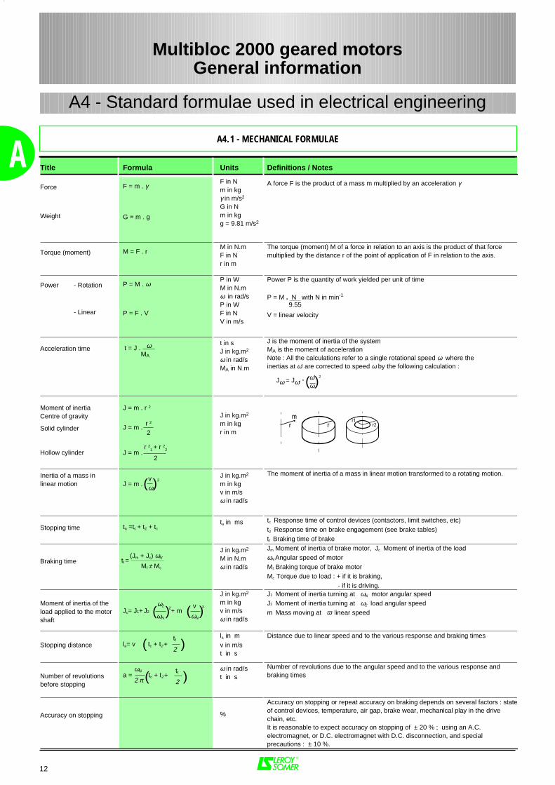
A Title Formula Units Definitions / Notes
Force
Weight
F = m . γ
G = m . g
F in Nm in kgγ in m/s2
G in Nm in kgg = 9.81 m/s2
A force F is the product of a mass m multiplied by an acceleration γ
Torque (moment) M = F . rM in N.mF in Nr in m
The torque (moment) M of a force in relation to an axis is the product of that forcemultiplied by the distance r of the point of application of F in relation to the axis.
Power - Rotation
- Linear
P = M . ω
P = F . V
P in WM in N.mω in rad/sP in WF in NV in m/s
Power P is the quantity of work yielded per unit of time
P = M . N with N in min-1
V = linear velocity
Acceleration time ω MA
t in sJ in kg.m2
ω in rad/sMA in N.m
J is the moment of inertia of the systemMA is the moment of accelerationNote : All the calculations refer to a single rotational speed ω where theinertias at ω' are corrected to speed ω by the following calculation :
Jω = Jω' . ω' 2
ω
Moment of inertiaCentre of gravity
Solid cylinder
Hollow cylinder
J = m . r 2
J = m .
J = m .
J in kg.m2
m in kgr in m
Inertia of a mass inlinear motion J = m .
2J in kg.m2
m in kgv in m/sω in rad/s
The moment of inertia of a mass in linear motion transformed to a rotating motion.
Stopping time ta =tc + t2 + tc
ta in ms tc Response time of control devices (contactors, limit switches, etc)t2 Response time on brake engagement (see brake tables)tf Braking time of brake
Braking time
(Jm + Jc) ωΝ
Mf ± Mc
J in kg.m2
M in N.mω in rad/s
Jm Moment of inertia of brake motor, Jc Moment of inertia of the loadωΝ Angular speed of motorMf Braking torque of brake motor Mc Torque due to load : + if it is braking, - if it is driving.
Moment of inertia of theload applied to the motorshaft
Jc= J1+ J2 2+ m
2
J in kg.m2
m in kgv in m/sω in rad/s
J1 Moment of inertia turning at ωΝ motor angular speedJ2 Moment of inertia turning at ω2 load angular speedm Mass moving at ϖ linear speed
Stopping distance la= v tc + t2 +la in mv in m/st in s
Distance due to linear speed and to the various response and braking times
Number of revolutionsbefore stopping
a = tc + t2 +ω in rad/st in s
Number of revolutions due to the angular speed and to the various response andbraking times
Accuracy on stopping %
Accuracy on stopping or repeat accuracy on braking depends on several factors : stateof control devices, temperature, air gap, brake wear, mechanical play in the drivechain, etc.It is reasonable to expect accuracy on stopping of ± 20 % ; using an A.C.electromagnet, or D.C. electromagnet with D.C. disconnection, and specialprecautions : ± 10 %.
t = J .
( )
r 2
2
r 21
+ r 22
2
r1r2rr
m
( )vω
tf =
( ) ω2
ωΝ( ) v
ωΝ
( )tf
2
( )tf
2
ωΝ
2 π
9.55
A4.1 - MECHANICAL FORMULAE
A4 - Standard formulae used in electrical engineering
Multibloc 2000 geared motorsGeneral information
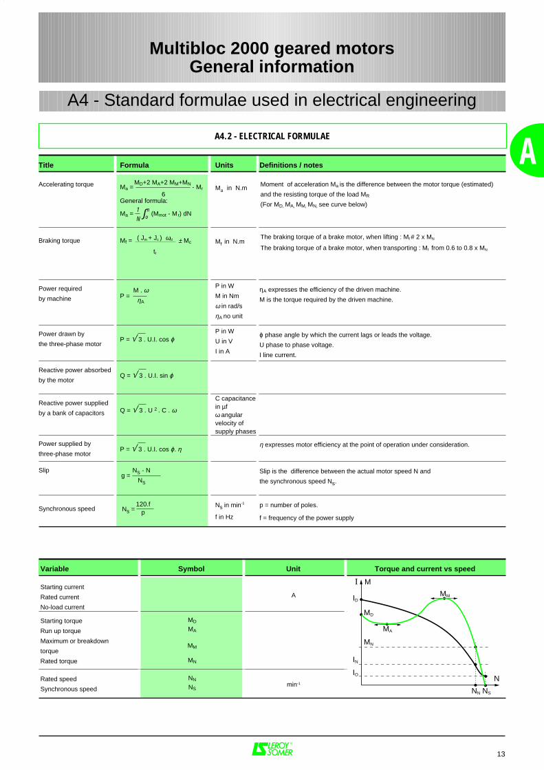
ATitle Formula Units Definitions / notes
Accelerating torque
Ma = - Mr
General formula:
Ma = (Mmot - M r) dN
Ma in N.m Moment of acceleration Ma is the difference between the motor torque (estimated)
and the resisting torque of the load MR
(For MD, MA, MM, MN, see curve below)
Braking torque Mf = ± Mc Mf in N.mThe braking torque of a brake motor, when lifting : Mf # 2 x MN
The braking torque of a brake motor, when transporting : Mf from 0.6 to 0.8 x MN
Power required
by machine P =
P in W
M in Nm
ω in rad/s
ηA no unit
ηA expresses the efficiency of the driven machine.
M is the torque required by the driven machine.
Power drawn by
the three-phase motorP = √ 3 . U.I. cos ϕ
P in W
U in V
I in A
ϕ phase angle by which the current lags or leads the voltage.
U phase to phase voltage.
I line current.
Reactive power absorbed
by the motorQ = √ 3 . U.I. sin ϕ
Reactive power supplied
by a bank of capacitors Q = √ 3 . U 2 . C . ω
C capacitancein µfω angularvelocity ofsupply phases
Power supplied by
three-phase motorP = √ 3 . U.I. cos ϕ. η
η expresses motor efficiency at the point of operation under consideration.
Slip NS - N
NS
Slip is the difference between the actual motor speed N and
the synchronous speed Ns.
Synchronous speed 120.f p
Ns in min-1
f in Hz
p = number of poles.
f = frequency of the power supply
Variable Symbol Unit Torque and current vs speed
Starting current
Rated current
No-load current
A
Starting torque
Run up torque
Maximum or breakdown
torque
Rated torque
MD
MA
MM
MN
Rated speed
Synchronous speed
NN
NSmin-1
g =
Ns =
1N
n
MD+2 MA+2 MM+MN
6
M . ωηA
∫o
( Jm + Jc ) ωN
tf
13
A4.2 - ELECTRICAL FORMULAE
A4 - Standard formulae used in electrical engineering
Multibloc 2000 geared motorsGeneral information
I M
ID
MD
MN
IN
IO
MA
MM
NN NS
N
14
A
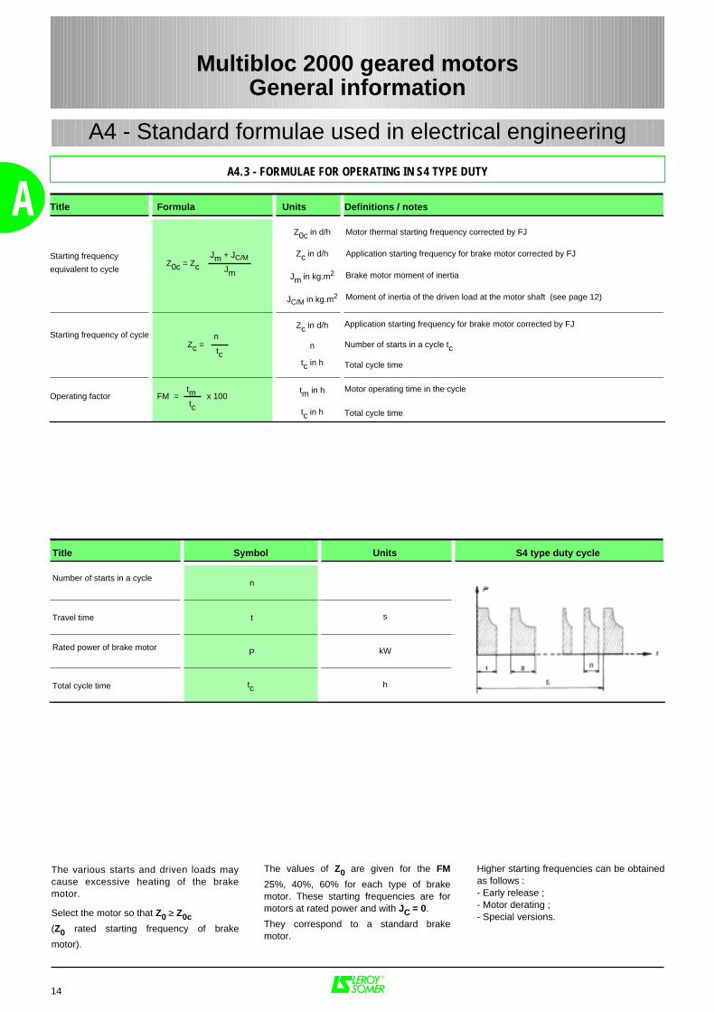
The various starts and driven loads maycause excessive heating of the brakemotor.
Select the motor so that Z0 ≥ Z0c (Z0 rated starting frequency of brake
motor).
The values of Z0 are given for the FM
25%, 40%, 60% for each type of brakemotor. These starting frequencies are formotors at rated power and with JC = 0.
They correspond to a standard brakemotor.
Higher starting frequencies can be obtainedas follows :- Early release ;- Motor derating ;- Special versions.
A4.3 - FORMULAE FOR OPERATING IN S4 TYPE DUTY
Multibloc 2000 geared motorsGeneral information
A4 - Standard formulae used in electrical engineering
Title Formula Units Definitions / notes
Starting frequency
equivalent to cycle Z0c = Zc
Z0c in d/h
Zc in d/h
Jm in kg.m2
JC/M in kg.m2
Motor thermal starting frequency corrected by FJ
Application starting frequency for brake motor corrected by FJ
Brake motor moment of inertia
Moment of inertia of the driven load at the motor shaft (see page 12)
Starting frequency of cycle Zc =
Zc in d/h
n
tc in h
Application starting frequency for brake motor corrected by FJ
Number of starts in a cycle tc
Total cycle time
Operating factor FM = x 100tm in h
tc in h
Motor operating time in the cycle
Total cycle time
Jm + JC/M
Jm
n
tc
tm
tc
Title Symbol Units S4 type duty cycle
Number of starts in a cycle n
Travel time t s
Rated power of brake motor P kW
Total cycle time tc h
15
B
Multibloc 2000 geared motorsEnvironment
B1 - Definition of indices of protection 17
B2 - Environmental limitations 18
B2.1 - Normal operating conditions ................................................................................................... 18
B2.2 - Correction according to altitude and ambient temperature ..................................................... . 18
B2.3 - Relative and absolute humidity ............................................................................................... 18
B2.4 - Drain holes .............................................................................................................................. 19
B2.5 - Drip covers .............................................................................................................................. 19
B3 - Impregnation and enhanced protection 20
B3.1 - Normal atmospheric pressure ................................................................................................. 20
B3.2 - Influence of atmospheric pressure .......................................................................................... 21
B4 - Heaters 22
B4.1 - Space heaters ......................................................................................................................... 22
B4.2 - D.C. injection ........................................................................................................................... 22
B4.3 - A.C. injection ........................................................................................................................... 22
B5 - External finish 23
B5.1 - Preparation of surfaces ........................................................................................................... 23
B5.2 - Definition of atmospheres ....................................................................................................... 23
B5.3 - Painting systems ..................................................................................................................... 23
B6 - Interference suppression 24
PAGES
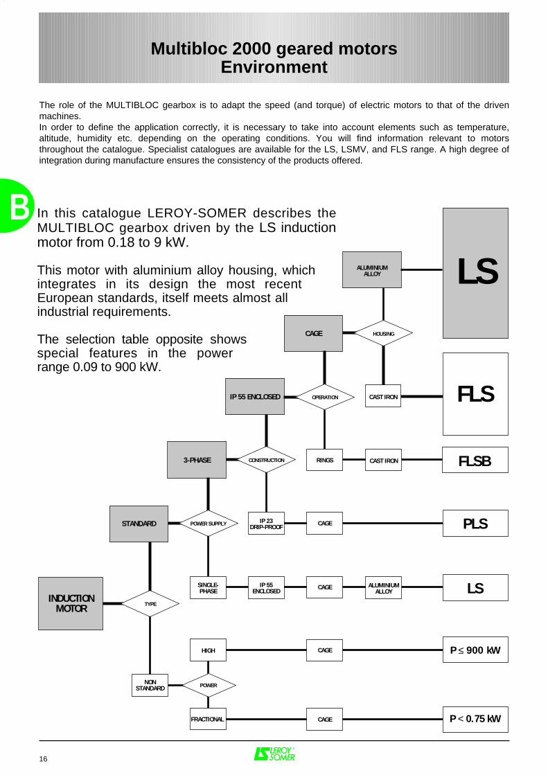
In this catalogue LEROY-SOMER describes the MULTIBLOC gearbox driven by the LS induction motor from 0.18 to 9 kW.
This motor with aluminium alloy housing, which integrates in its design the most recent European standards, itself meets almost all industrial requirements.
The selection table opposite shows special features in the power range 0.09 to 900 kW.
POWER
TYPE
NONSTANDARD
HIGH
FRACTIONAL
POWER SUPPLY
SINGLE-PHASE
CONSTRUCTION
IP 23DRIP-PROOF
OPERATION
RINGS
HOUSING
CAST IRON
CAST IRON
IP 55ENCLOSED
ALUMINIUMALLOY
LS
FLS
FLSB
PLS
LS
P < 0.75 kW
CAGE
CAGE
CAGE
CAGE
3-PHASE
IP 55 ENCLOSED
CAGE
ALUMINIUMALLOY
INDUCTIONMOTOR
STANDARD
P ≤ 900 kW
B
16
Multibloc 2000 geared motorsEnvironment
The role of the MULTIBLOC gearbox is to adapt the speed (and torque) of electric motors to that of the drivenmachines. In order to define the application correctly, it is necessary to take into account elements such as temperature,altitude, humidity etc. depending on the operating conditions. You will find information relevant to motorsthroughout the catalogue. Specialist catalogues are available for the LS, LSMV, and FLS range. A high degree ofintegration during manufacture ensures the consistency of the products offered.
IP0
1
2
3
4
5
Tests Definition IP Tests Definition IK Tests Definition
First number :protection against solid objects mechanical protection
Ø 50 mm
Ø 12 mm
No protection
Protected againstsolid objects ofover 12 mm(eg : finger)
Protected againstsolid objects of over 50 mm(eg : accidentalhand contact)
Protected againstsolid objects ofover 2.5 mm(eg : tools, wire)
Ø 2.5 mm
Protected againstsolid objectsof over 1 mm(eg : small tools, thin wire)
Ø 1 mm
Second number :protection against liquids
0 No protection 00 No protection
1
15°
2
3
4
60°
5
6
7
8
..m
0,
15 m
1 m
Protected againstdust (no depositsof harmful material)
Protected againstthe effects of prolonged immersion underpressure
Protected againstthe effects of immersion to depths of between 0.15 and 1 m
Protected againstjets of watercomparable to heavy seas
Protected againstjets of water fromall directions
Protected againstwater splashesfrom all directions
Protected againstrain falling at up to 60° from the vertical
Protected againstwater drippingup to 15° fromthe vertical
Protected againstvertically drippingwater(condensation)
01 Impact energy :0.15 J
02 Impact energy :0.20 J
03 Impact energy :0.37 J
05 Impact energy :0.70 J
07 Impact energy :2 J
09 Impact energy :10 J
150 g
10 cm
250 g
15 cm
250 g
20 cm
250 g40 cm
0.5 kg40 cm
2.5 kg40 cm
. . m
200 g
10 cm
350 g
20 cm
04
06
081.25 kg
40 cm
10 Impact energy :20 J
5 kg40 cm
Impact energy :5 J
Impact energy :1 J
Impact energy :0.50 J
17
B
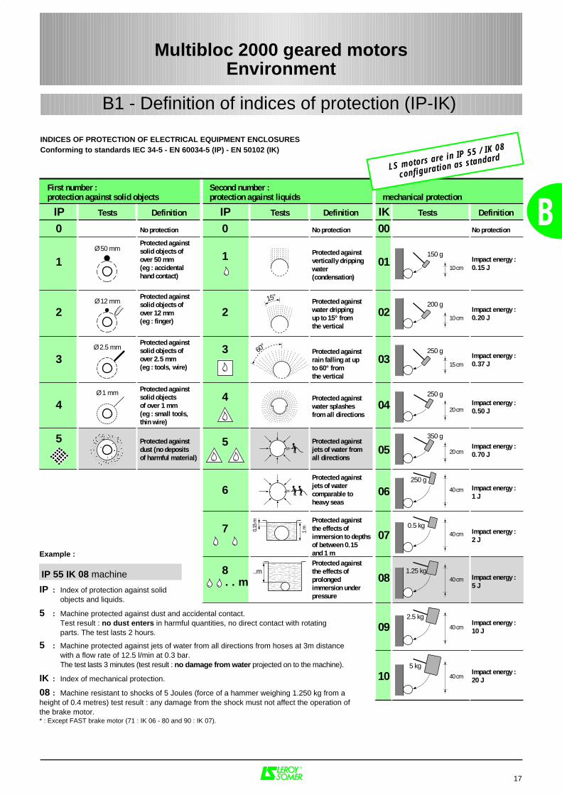
Example :
IP 55 IK 08 machine
IP : Index of protection against solid objects and liquids.
5 : Machine protected against dust and accidental contact.Test result : no dust enters in harmful quantities, no direct contact with rotating parts. The test lasts 2 hours.
5 : Machine protected against jets of water from all directions from hoses at 3m distance with a flow rate of 12.5 l/min at 0.3 bar.The test lasts 3 minutes (test result : no damage from water projected on to the machine).
IK : Index of mechanical protection.
08 : Machine resistant to shocks of 5 Joules (force of a hammer weighing 1.250 kg from aheight of 0.4 metres) test result : any damage from the shock must not affect the operation ofthe brake motor.* : Except FAST brake motor (71 : IK 06 - 80 and 90 : IK 07).
INDICES OF PROTECTION OF ELECTRICAL EQUIPMENT ENCLOSURESConforming to standards IEC 34-5 - EN 60034-5 (IP) - EN 50102 (IK)
Multibloc 2000 geared motorsEnvironment
B1 - Definition of indices of protection (IP-IK)
LS motors are in IP 55 / IK 08
configuration as standard
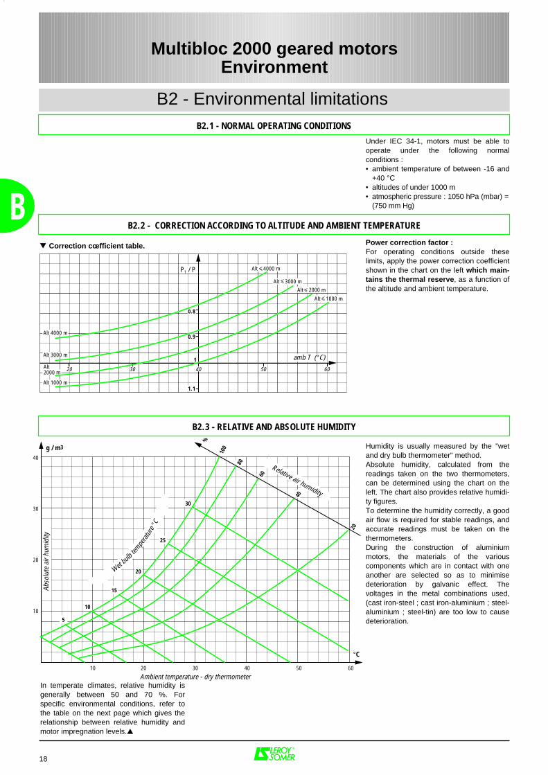
Under IEC 34-1, motors must be able tooperate under the following normalconditions :• ambient temperature of between -16 and
+40 °C• altitudes of under 1000 m• atmospheric pressure : 1050 hPa (mbar) =
(750 mm Hg)
Power correction factor :For operating conditions outside theselimits, apply the power correction coefficientshown in the chart on the left which main-tains the thermal reserve, as a function ofthe altitude and ambient temperature.
Humidity is usually measured by the "wetand dry bulb thermometer" method.Absolute humidity, calculated from thereadings taken on the two thermometers,can be determined using the chart on theleft. The chart also provides relative humidi-ty figures.To determine the humidity correctly, a goodair flow is required for stable readings, andaccurate readings must be taken on thethermometers.During the construction of aluminiummotors, the materials of the variouscomponents which are in contact with oneanother are selected so as to minimisedeterioration by galvanic effect. Thevoltages in the metal combinations used,(cast iron-steel ; cast iron-aluminium ; steel-aluminium ; steel-tin) are too low to causedeterioration.
18
B
B2 - Environmental limitationsB2.1 - NORMAL OPERATING CONDITIONS
Correction cœfficient table.
In temperate climates, relative humidity isgenerally between 50 and 70 %. Forspecific environmental conditions, refer tothe table on the next page which gives therelationship between relative humidity andmotor impregnation levels.
Multibloc 2000 geared motorsEnvironment
B2.2 - CORRECTION ACCORDING TO ALTITUDE AND AMBIENT TEMPERATURE
B2.3 - RELATIVE AND ABSOLUTE HUMIDITY
Alt 1000 m
Alt 2000 mAlt 3000 m
Alt 4000 m
Alt 1000 m
1
P1 / P
20 605030 40
1.1
0.8
0.9Alt 4000 m
Alt 3000 m amb T (°C)Alt2000 m
10
Ambient temperature - dry thermometer
Abso
lute
air
hum
idity
20 30 40 50 60
10
20
30
40
5
10
15
20
25
30
Wet bulbtem
perat
ur
e °C
°C
g / m3
20
40
60
80
100
%
Relative air humidity
B
B2 - Environmental limitations
B2.4 - DRAIN HOLES
Holes are provided at the lowest points ofthe enclosure, depending on their operatingposition (IM, etc), to drain off any moisturethat may have accumulated inside duringcooling of the machine.The holes may be sealed in various ways :- standard : with plastic plugs,- on request : with screws, syphon or plasticventilator.
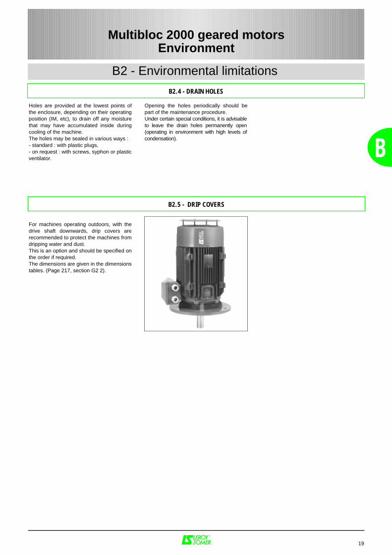
For machines operating outdoors, with thedrive shaft downwards, drip covers arerecommended to protect the machines fromdripping water and dust.This is an option and should be specified onthe order if required.The dimensions are given in the dimensionstables. (Page 217, section G2 2).
Opening the holes periodically should bepart of the maintenance procedure.Under certain special conditions, it is advisableto leave the drain holes permanently open(operating in environment with high levels ofcondensation).
19
Multibloc 2000 geared motorsEnvironment
B2.5 - DRIP COVERS
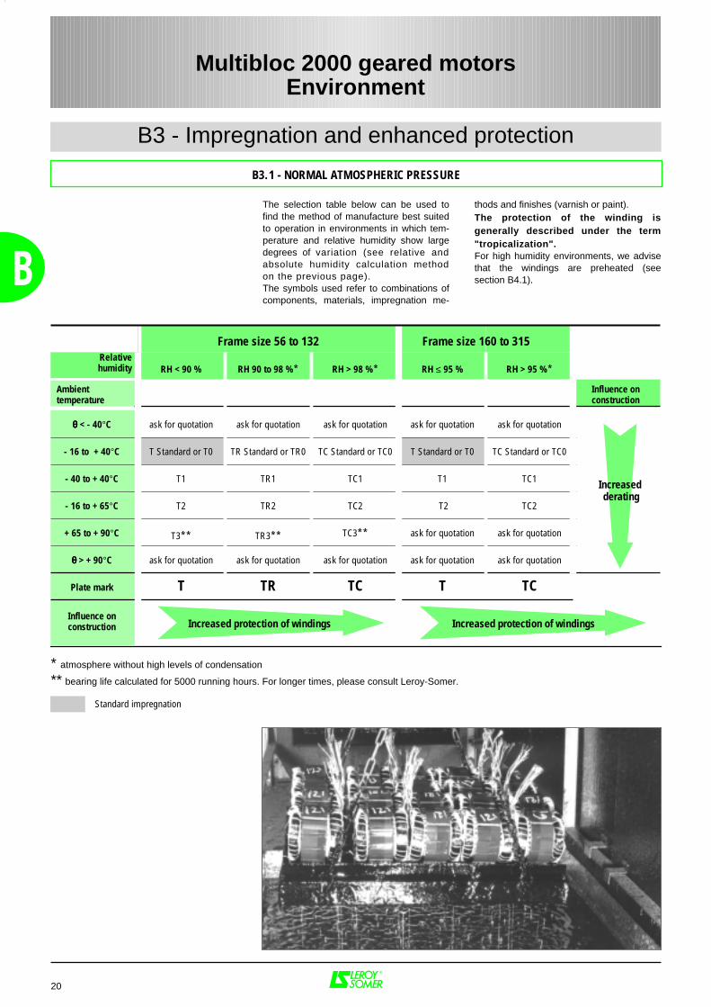
The selection table below can be used tofind the method of manufacture best suitedto operation in environments in which tem-perature and relative humidity show largedegrees of variation (see relative andabsolute humidity calculation methodon the previous page).The symbols used refer to combinations ofcomponents, materials, impregnation me-
thods and finishes (varnish or paint).The protection of the winding isgenerally described under the term"tropicalization".For high humidity environments, we advisethat the windings are preheated (seesection B4.1).
20
B3 - Impregnation and enhanced protection
B
* atmosphere without high levels of condensation
** bearing life calculated for 5000 running hours. For longer times, please consult Leroy-Somer.
Frame size 160 to 315
Standard impregnation
Multibloc 2000 geared motorsEnvironment
Frame size 56 to 132 Frame size 160 to 315Relativehumidity RH < 90 % RH 90 to 98 %* RH > 98 %* RH ≤ 95 % RH > 95 %*
Ambienttemperature
Influence onconstruction
θθθθ < - 40°C ask for quotation ask for quotation ask for quotation ask for quotation ask for quotation
- 16 to + 40°C T Standard or T0 TR Standard or TR0 TC Standard or TC0 T Standard or T0 TC Standard or TC0
- 40 to + 40°C T1 TR1 TC1 T1 TC1
- 16 to + 65°C T2 TR2 TC2 T2 TC2 Declassementcroissant
+ 65 to + 90°C T3** TR3** TC3** ask for quotation ask for quotation
θθθθ > + 90°C ask for quotation ask for quotation ask for quotation ask for quotation ask for quotation
Plate mark T TR TC T TC
Influence onconstruction Increased protection of windings Increased protection of windings
B3.1 - NORMAL ATMOSPHERIC PRESSURE
Increased protection of windings Increased protection of windings
Increased derating
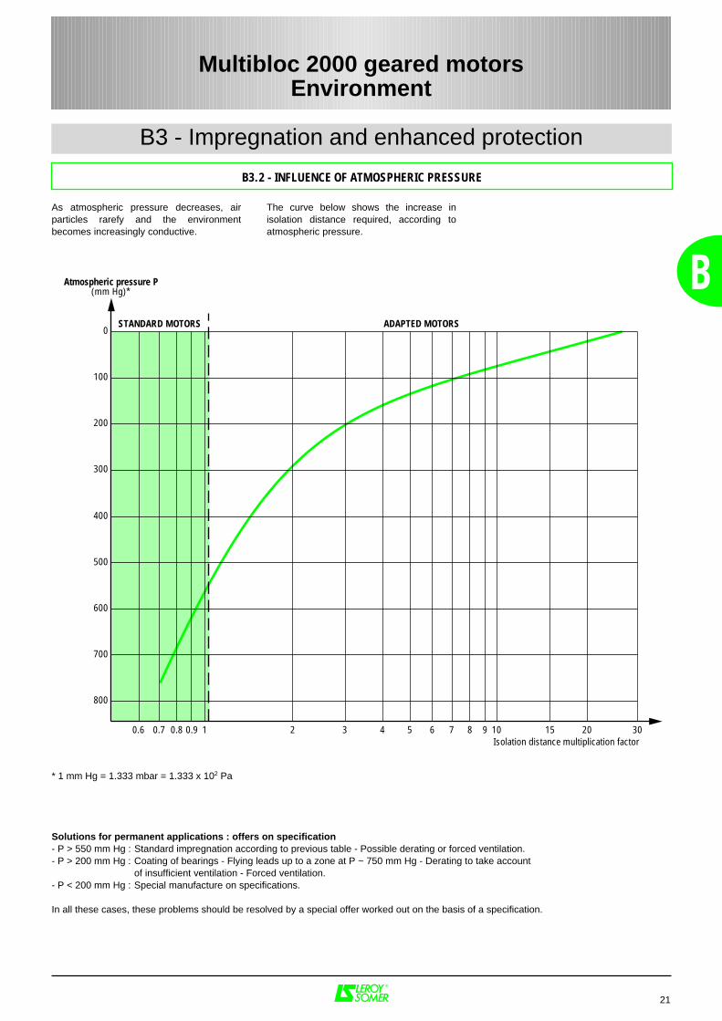
The curve below shows the increase inisolation distance required, according toatmospheric pressure.
As atmospheric pressure decreases, airparticles rarefy and the environmentbecomes increasingly conductive.
21
B
Multibloc 2000 geared motorsEnvironment
B3 - Impregnation and enhanced protection
B3.2 - INFLUENCE OF ATMOSPHERIC PRESSURE
0.6 0.7 0.8 0.9 1 2 3 4 5 6 7 8 9 10 15 20 30
800
700
600
500
400
300
200
100
0
Isolation distance multiplication factor
STANDARD MOTORS ADAPTED MOTORS
Atmospheric pressure P(mm Hg)*
* 1 mm Hg = 1.333 mbar = 1.333 x 10² Pa
Solutions for permanent applications : offers on specification- P > 550 mm Hg : Standard impregnation according to previous table - Possible derating or forced ventilation.- P > 200 mm Hg : Coating of bearings - Flying leads up to a zone at P ~ 750 mm Hg - Derating to take account
of insufficient ventilation - Forced ventilation.- P < 200 mm Hg : Special manufacture on specifications.
In all these cases, these problems should be resolved by a special offer worked out on the basis of a specification.
22
B4 - Heaters
B
Severe climatic conditions, for example T amb < - 40°C, RH > 95 %, etc, may require the useof space heaters (fitted to either or both winding end coils) which serve to maintain theaverage temperature of the motor, provide trouble-free starting and/or eliminate problemscaused by condensation (loss of insulation).The heater supply wires are brought out to a terminal block in the motor terminal box. Theheaters must be switched off while the machine is in operation.
Type of motor No. of poles Power : P(W)
LS 71 2 - 4 - 6 - 8 10
LS 80 2 - 4 - 6 - 8 10
LS 90 to LS 132 2 - 4 - 6 - 8 25
LS 160 to LS 180 2 - 4 - 6 - 8 50
LS 200 to LS 225 2 - 4 - 6 - 8 50
LS 2502
4 - 6 - 8
50
80
LS 280 to LS 3152
4 - 6 - 8
80
100
The space heaters use 200/240V, single-phase, 50 or 60 Hz.
An alternative to the use of space heaters is to inject direct current into two of the phaseswired in series from a D.C. voltage source which can give the total power indicated in thetable above. This method can only be used on motors of less than 10 kW.To calculate the D.C. voltage, use the equation :
U(V) = √ P(w) . R (Ω)
where R is the resistance of the windings in series.
Resistance should be measured with a suitable ohmmeter.
A single-phase A.C. voltage (10 to 15 % of rated voltage) can be used between 2 phasesplaced in series. This method can be used on the whole LS range.
Multibloc 2000 geared motorsEnvironment
B4.1 - SPACE HEATERS
B4.2 - D.C. INJECTION
B4.3 - A.C INJECTION
PRODUCTS ATMOSPHERE SYSTEM APPLICATIONS SHEET
Standard finish Clean, dry (indoors, rural or industrial) System I a 1 coat polyurethane finish 25/30 µm 100
Finish : Optional
Moderately corrosive :humid, outdoors (temperate climate)
System II a 1 base coat epoxy 30/40 µm1 coat polyurethane finish 20/30 µm
101
Chemical attack (accidental splashing)suitable for foodstuffs and heavy industry
System II b 1 base coat epoxy 30/40 µm1 coat epoxy finish 25/35 µm
132
Corrosive : coastal, very humid(tropical climate) System III a
1 base coat epoxy 30 to 40 µ as well as inside end shields1 intermediate coat epoxy 30 to 40 µm
1 coat polyurethane finish 20/30 µm
102
Significant chemical attack : frequent contact withbase materials, acids, alkalines.
Special environment : neutral environment (no chlorinated or sulphurous products)
System III bSANDBLAST GEARED MOTOR BEFORE PAINTING
1 base coat epoxy 30 to 40 µ as well as inside end shields1 intermediate coat epoxy 30 to 40 µm
1 coat epoxy finish 25/35 µm
106
Painting system for special environments,aggressive atmosphere (chlorinated or sulphurous
products. Contact with bases,acids and alkalines)
System V eSANDBLAST GEARED MOTOR BEFORE PAINTING
1 base coat epoxy 30 to 40 µ as well as inside end shields3 intermediate coats epoxy 30 to 40 µm each
1 coat polyurethane finish 25/35 µm
140
B
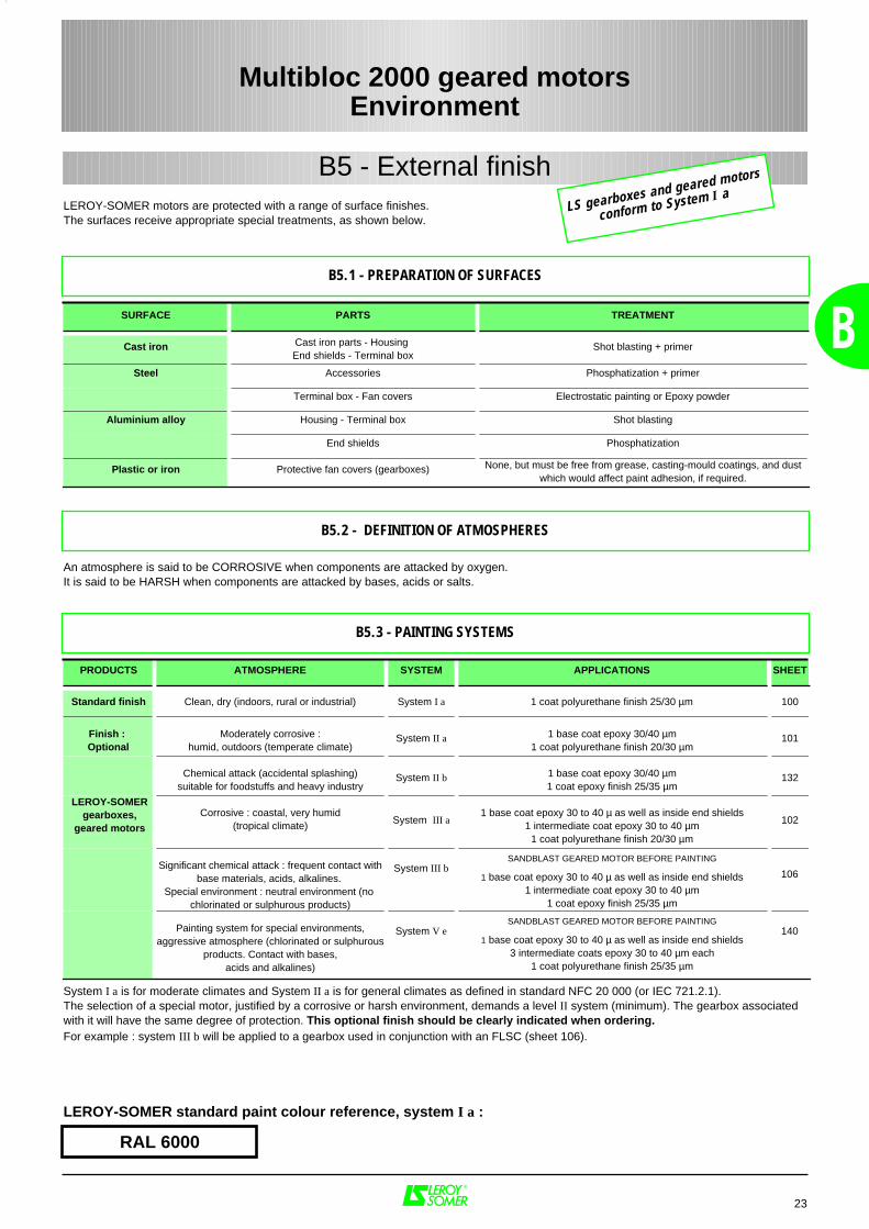
LEROY-SOMER motors are protected with a range of surface finishes.The surfaces receive appropriate special treatments, as shown below.
SURFACE PARTS TREATMENT
Cast iron Cast iron parts - Housing End shields - Terminal box
Shot blasting + primer
Steel Accessories Phosphatization + primer
Terminal box - Fan covers Electrostatic painting or Epoxy powder
Aluminium alloy Housing - Terminal box Shot blasting
End shields Phosphatization
Plastic or iron Protective fan covers (gearboxes) None, but must be free from grease, casting-mould coatings, and dustwhich would affect paint adhesion, if required.
LEROY-SOMER standard paint colour reference, system I a :
System I a is for moderate climates and System II a is for general climates as defined in standard NFC 20 000 (or IEC 721.2.1).The selection of a special motor, justified by a corrosive or harsh environment, demands a level II system (minimum). The gearbox associatedwith it will have the same degree of protection. This optional finish should be clearly indicated when ordering.For example : system III b will be applied to a gearbox used in conjunction with an FLSC (sheet 106).
RAL 6000
23
B5.1 - PREPARATION OF SURFACES
B5.3 - PAINTING SYSTEMS
Multibloc 2000 geared motorsEnvironment
B5 - External finish
B5.2 - DEFINITION OF ATMOSPHERES
An atmosphere is said to be CORROSIVE when components are attacked by oxygen.It is said to be HARSH when components are attacked by bases, acids or salts.
LEROY-SOMERgearboxes,
geared motors
LS gearboxes and geared motors
conform to System I a
Airborne interference
EmissionFor standard motors, the housing acts asan electromagnetic screening, reducingelectromagnetic emissions measured at0.25 metres from the motor toapproximately 5 gauss (5 x 10⁻⁴ T).
However, electromagnetic emissions maybe noticeably reduced by a specialconstruction of aluminium alloy end shieldsand a stainless steel shaft.
ImmunityThe construction of motor housings(especially the finned aluminium alloyhousing) isolates external electromagneticsources to the extent that any fieldpenetrating the casing and magnetic circuitwill be too weak to interfere with theoperation of the motor.
Power supply interferenceThe use of electronic systems for starting,speed control or power supply can createharmonics on the supply lines which mayinterfere with the operation of machines.These phenomena are taken into account indetermining the machine dimensions, whichact as quenching chokes in this respect.Standard IEC 1000, currently inpreparation, will define permissible rejectionand immunity rates. Only then will machinesfor general distribution (especially single-phase and commutator motors) have to befitted with interference suppressionsystems.Three-phase squirrel cage motors do not inthemselves produce interference of thistype. Mains connection equipment(contactors) may, however, needinterference protection.
24
B6 - Interference suppression
B
Application of Directive 89-336 modified byDirectives 92-31 and 93-68 concerningelectromagnetic compatibility (EMC).
a - for motors only :According to amendment 1 of IEC 34-1,induction motors are neither transmittersnor receivers (of carried or airborne signals)and therefore conform inherently to theessential requirements of the EMCdirectives.
b - for motors supplied by inverters (at fixedor variable basic frequency) :In this case, the motor is only a sub-assembly of a device which the systembuilder must ensure conforms to theessential requirements of the EMCdirectives.
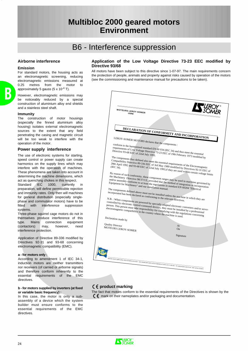
Application of the Low Voltage Directive 73-23 EEC modified byDirective 93/68All motors have been subject to this directive since 1-07-97. The main requirements concernthe protection of people, animals and property against risks caused by operation of the motors(see the commissioning and maintenance manual for precautions to be taken).
product markingThe fact that motors conform to the essential requirements of the Directives is shown by the mark on their nameplates and/or packaging and documentation.
Multibloc 2000 geared motorsEnvironment
LEROY-SOMER MOTORS declares that the components :conform to the harmonized standard EN 60 034 (IEC 34) and thus meet the essential
requirements of Low Voltage Directive 73-23 EEC of 19th February 1973 modified by
Directive 93-68 EEC of 22nd July 1993.The components thus defined also meet the essential requirements of the Electromagnetic
Compatibility Directive 89-336 EEC of 3rd May 1989 modified by Directives 92-31 EEC of
28th April 1992 and 93-68 EEC of 22nd July 1993,if they are used within certain voltage limits
(IEC 34).
By reason of such conformity, these component ranges may be used in machines governed by
the Machinery Directive 98/37/CE, provided that the method of integration or incorporation
and/or assembly conforms to at least the regulations in standard EN 60204 "Electrical
Equipment for Machinery" and our installation manual.The components defined above must not be installed unless the machine in which they are
incorporated has been declared as conforming to the relevant directives.N.B. : When components are powered by specially adapted electronic converters and/or servo-
controlled by electronic control-command devices, they must be installed by a professional
person. This person must take responsibility for complying with the regulations concerning
electromagnetic compatibility in the country where the machine is used.Declaration made by AtOn
Quality DirectorMOTEURS LEROY-SOMER Signature
MOTEURS LEROY-SOMERUSINE
DECLARATION OF CONFORMITY AND INCORPORATION
MOTEURS LEROY-SOMER (SIEGE SOCIAL BD MARCELLIN LEROY - 16015 ANGOULEME CEDEX) SOCIETE ANONYME AU CAPITAL DE 411 800 000 F - RCS ANGOULEME B 338 567 258 - SIRET 338 567 258 00011
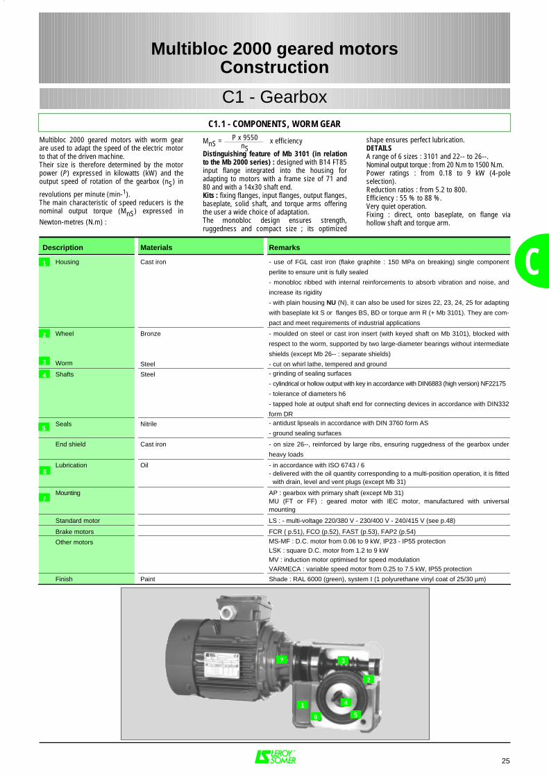
Multibloc 2000 geared motors with worm gearare used to adapt the speed of the electric motorto that of the driven machine.Their size is therefore determined by the motorpower (P) expressed in kilowatts (kW) and theoutput speed of rotation of the gearbox (nS) in
revolutions per minute (min-1).The main characteristic of speed reducers is thenominal output torque (MnS) expressed inNewton-metres (N.m) :
MnS = x efficiency
Distinguishing feature of Mb 3101 (in relationto the Mb 2000 series) : designed with B14 FT85input flange integrated into the housing foradapting to motors with a frame size of 71 and80 and with a 14x30 shaft end.Kits : fixing flanges, input flanges, output flanges,baseplate, solid shaft, and torque arms offeringthe user a wide choice of adaptation.The monobloc design ensures strength,ruggedness and compact size ; its optimized
C
25
Multibloc 2000 geared motorsConstruction
C1 - GearboxC1.1 - COMPONENTS, WORM GEAR
Description Materials Remarks
Housing Cast iron - use of FGL cast iron (flake graphite : 150 MPa on breaking) single component
perlite to ensure unit is fully sealed
- monobloc ribbed with internal reinforcements to absorb vibration and noise, and
increase its rigidity
- with plain housing NU (N), it can also be used for sizes 22, 23, 24, 25 for adapting
with baseplate kit S or flanges BS, BD or torque arm R (+ Mb 3101). They are com-
pact and meet requirements of industrial applications
Wheel
Worm
Bronze
Steel
- moulded on steel or cast iron insert (with keyed shaft on Mb 3101), blocked with
respect to the worm, supported by two large-diameter bearings without intermediate
shields (except Mb 26-- : separate shields)
- cut on whirl lathe, tempered and ground
Shafts Steel - grinding of sealing surfaces
- cylindrical or hollow output with key in accordance with DIN6883 (high version) NF22175
- tolerance of diameters h6
- tapped hole at output shaft end for connecting devices in accordance with DIN332
form DR
Seals Nitrile - antidust lipseals in accordance with DIN 3760 form AS
- ground sealing surfaces
End shield Cast iron - on size 26--, reinforced by large ribs, ensuring ruggedness of the gearbox under
heavy loads
Lubrication Oil - in accordance with ISO 6743 / 6- delivered with the oil quantity corresponding to a multi-position operation, it is fitted
with drain, level and vent plugs (except Mb 31)
Mounting AP : gearbox with primary shaft (except Mb 31)MU (FT or FF) : geared motor with IEC motor, manufactured with universalmounting
Standard motor LS : - multi-voltage 220/380 V - 230/400 V - 240/415 V (see p.48)
Brake motors FCR ( p.51), FCO (p.52), FAST (p.53), FAP2 (p.54)
Other motors MS-MF : D.C. motor from 0.06 to 9 kW, IP23 - IP55 protectionLSK : square D.C. motor from 1.2 to 9 kWMV : induction motor optimised for speed modulationVARMECA : variable speed motor from 0.25 to 7.5 kW, IP55 protection
Finish Paint Shade : RAL 6000 (green), system I (1 polyurethane vinyl coat of 25/30 µm)
1
2
4
5
6
7
3
P x 9550nS
shape ensures perfect lubrication.DETAILSA range of 6 sizes : 3101 and 22-- to 26--.Nominal output torque : from 20 N.m to 1500 N.m.Power ratings : from 0.18 to 9 kW (4-poleselection).Reduction ratios : from 5.2 to 800.Efficiency : 55 % to 88 %.Very quiet operation.Fixing : direct, onto baseplate, on flange viahollow shaft and torque arm.
6
7
2
4
3
5
1
26
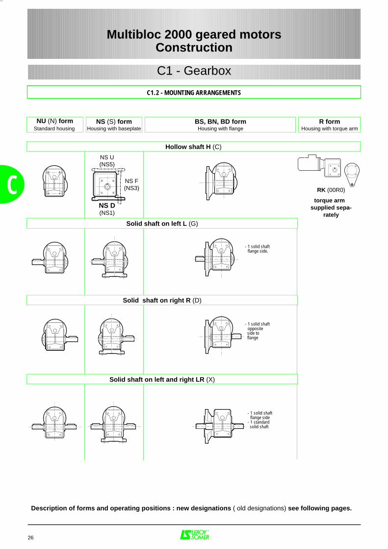
Description of forms and operating positions : new designations ( old designations) see following pages.
NU (N) formStandard housing
NS (S) formHousing with baseplate
BS, BN, BD formHousing with flange
R formHousing with torque arm
NS D(NS1)
NS U(NS5)
NS F(NS3)
- 1 solid shaft- flange side.
- 1 solid shaft- opposite side to flange
Hollow shaft H (C)
Solid shaft on left L (G)
Solid shaft on right R (D)
Solid shaft on left and right LR (X)
- 1 solid shaft- flange side- 1 standard solid shaft
RK (00R0)
torque arm supplied sepa-
rately
Multibloc 2000 geared motorsConstruction
C1 - Gearbox
C
C1.2 - MOUNTING ARRANGEMENTS
NU (N00)
27
Multibloc 2000 geared motorsConstruction
C1 - Gearbox
C
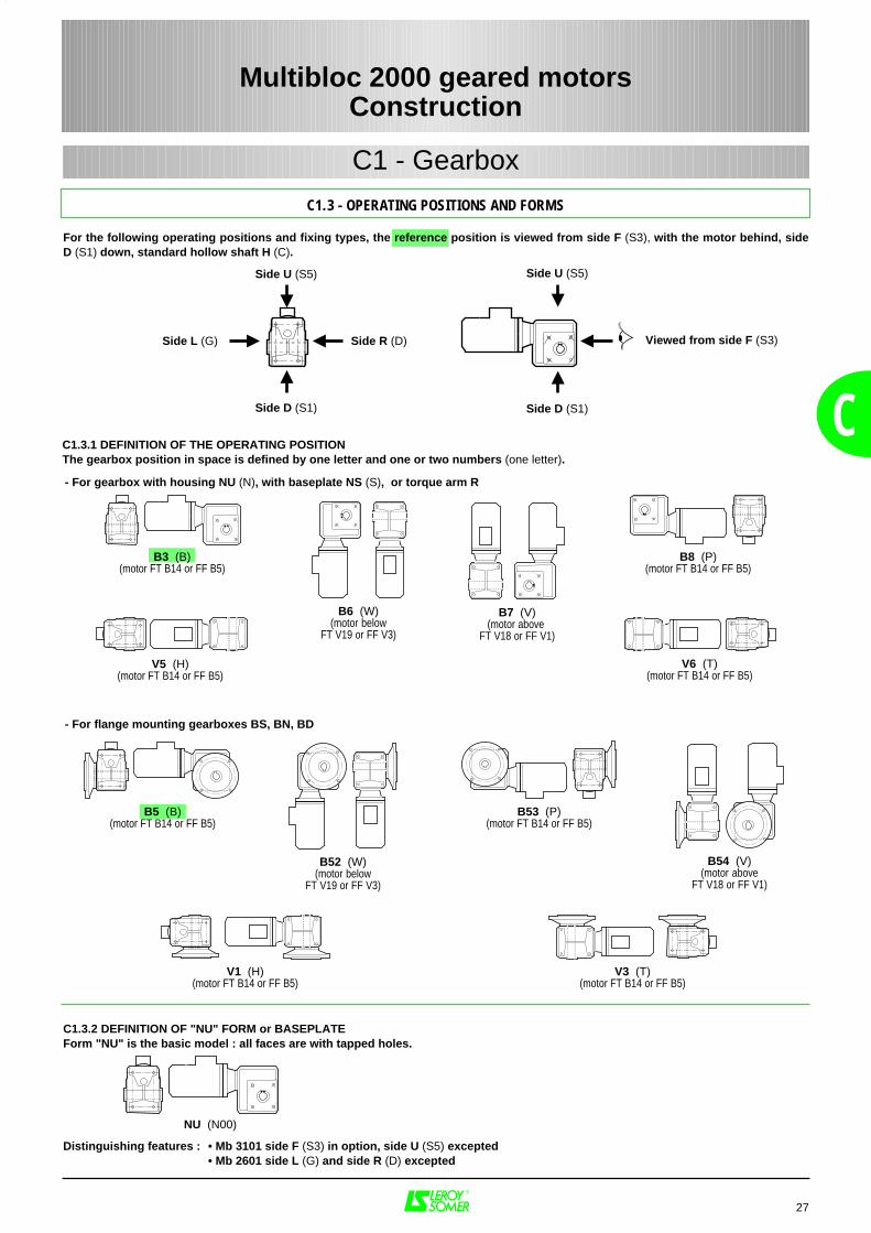
C1.3 - OPERATING POSITIONS AND FORMS
C1.3.1 DEFINITION OF THE OPERATING POSITIONThe gearbox position in space is defined by one letter and one or two numbers (one letter).
For the following operating positions and fixing types, the reference position is viewed from side F (S3), with the motor behind, sideD (S1) down, standard hollow shaft H (C).
- For gearbox with housing NU (N), with baseplate NS (S), or torque arm R
B3 (B)(motor FT B14 or FF B5)
B8 (P)(motor FT B14 or FF B5)
V5 (H)(motor FT B14 or FF B5)
B6 (W)(motor below
FT V19 or FF V3)
B7 (V)(motor above
FT V18 or FF V1)
V6 (T)(motor FT B14 or FF B5)
- For flange mounting gearboxes BS, BN, BD
B5 (B)(motor FT B14 or FF B5)
B52 (W)(motor below
FT V19 or FF V3)
B53 (P)(motor FT B14 or FF B5)
B54 (V)(motor above
FT V18 or FF V1)
V1 (H)(motor FT B14 or FF B5)
V3 (T)(motor FT B14 or FF B5)
Viewed from side F (S3)Side L (G) Side R (D)
Side U (S5)
Side D (S1)
Side U (S5)
Side D (S1)
C1.3.2 DEFINITION OF "NU" FORM or BASEPLATEForm "NU" is the basic model : all faces are with tapped holes.
Distinguishing features : • Mb 3101 side F (S3) in option, side U (S5) excepted• Mb 2601 side L (G) and side R (D) excepted
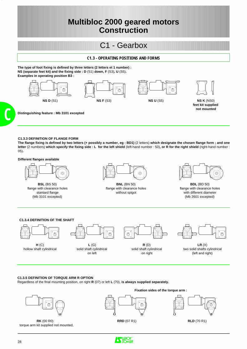
C1.3.4 DEFINITION OF THE SHAFT
H (C) L (G) R (D) LR (X)hollow shaft cylindrical solid shaft cylindrical solid shaft cylindrical two solid shafts cylindrical
on left on right (left and right)
28
Multibloc 2000 geared motorsConstruction
C1 - Gearbox
C1.3 - OPERATING POSITIONS AND FORMS
CC1.3.3 DEFINITION OF FLANGE FORM The flange fixing is defined by two letters (+ possibly a number, eg : BD1) (2 letters) which designate the chosen flange form ; and oneletter (2 numbers) which specify the fixing side : L for the left shield (left-hand number : 50), or R for the right shield (right-hand number :05).
Different flanges available
BSL (BS 50) BNL (BN 50) BDL (BD 50)flange with clearance holes flange with clearance holes flange with clearance holes
stantard flange without spigot with different diameter(Mb 3101 excepted) (Mb 2601 excepted)
C1.3.5 DEFINITION OF TORQUE ARM R OPTIONRegardless of the final mounting position, on right R (07) or left L (70), is always supplied separately.
Fixation sides of the torque arm :
The type of foot fixing is defined by three letters (2 letters et 1 number) :NS (separate feet kit) and the fixing side : D (S1) down, F (S3), U (S5).Examples in operating position B3 :
NS D (S1) NS F (S3) NS U (S5) NS K (NS0)feet kit supplied
not mountedDistinguishing feature : Mb 3101 excepted
RK (00 R0) RRD (07 R1) RLD (70 R1)torque arm kit supplied not mounted,
C1 - Gearbox
29
C
Multibloc 2000 geared motorsConstruction
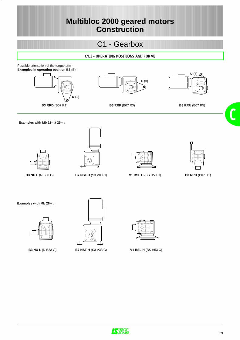
Possible orientation of the torque armExamples in operating position B3 (B) :
C1.3 - OPERATING POSITIONS AND FORMS
Examples with Mb 22-- à 25-- :
B3 NU L (N B00 G) B7 NSF H (S3 V00 C) V1 BSL H (BS H50 C) B8 RRD (P07 R1)
Examples with Mb 26-- :
B3 NU L (N B33 G) B7 NSF H (S3 V33 C) V1 BSL H (BS H53 C)
B3 RRD (B07 R1) B3 RRF (B07 R3) B3 RRU (B07 R5)
D (1)
F (3)
U (5)
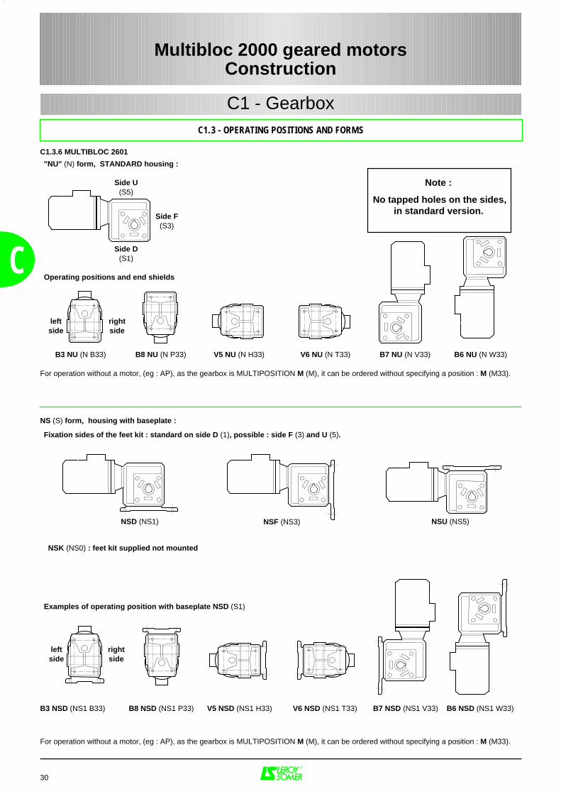
"NU" (N) form, STANDARD housing :
Operating positions and end shields
(Entre parenthèses:
B3 NU (N B33) B8 NU (N P33) V5 NU (N H33) V6 NU (N T33) B7 NU (N V33) B6 NU (N W33)
For operation without a motor, (eg : AP), as the gearbox is MULTIPOSITION M (M), it can be ordered without specifying a position : M (M33).
NS (S) form, housing with baseplate :
Fixation sides of the feet kit : standard on side D (1), possible : side F (3) and U (5).
NSK (NS0) : feet kit supplied not mounted
Examples of operating position with baseplate NSD (S1)
B3 NSD (NS1 B33) B8 NSD (NS1 P33) V5 NSD (NS1 H33) V6 NSD (NS1 T33) B7 NSD (NS1 V33) B6 NSD (NS1 W33)
For operation without a motor, (eg : AP), as the gearbox is MULTIPOSITION M (M), it can be ordered without specifying a position : M (M33).
30
C
Note :
No tapped holes on the sides,in standard version.
C1.3 - OPERATING POSITIONS AND FORMS
Multibloc 2000 geared motorsConstruction
C1.3.6 MULTIBLOC 2601
Side U(S5)
Side F(S3)
Side D(S1)
rightside
leftside
C1 - Gearbox
NSD (NS1) NSF (NS3) NSU (NS5)
rightside
leftside
31
C
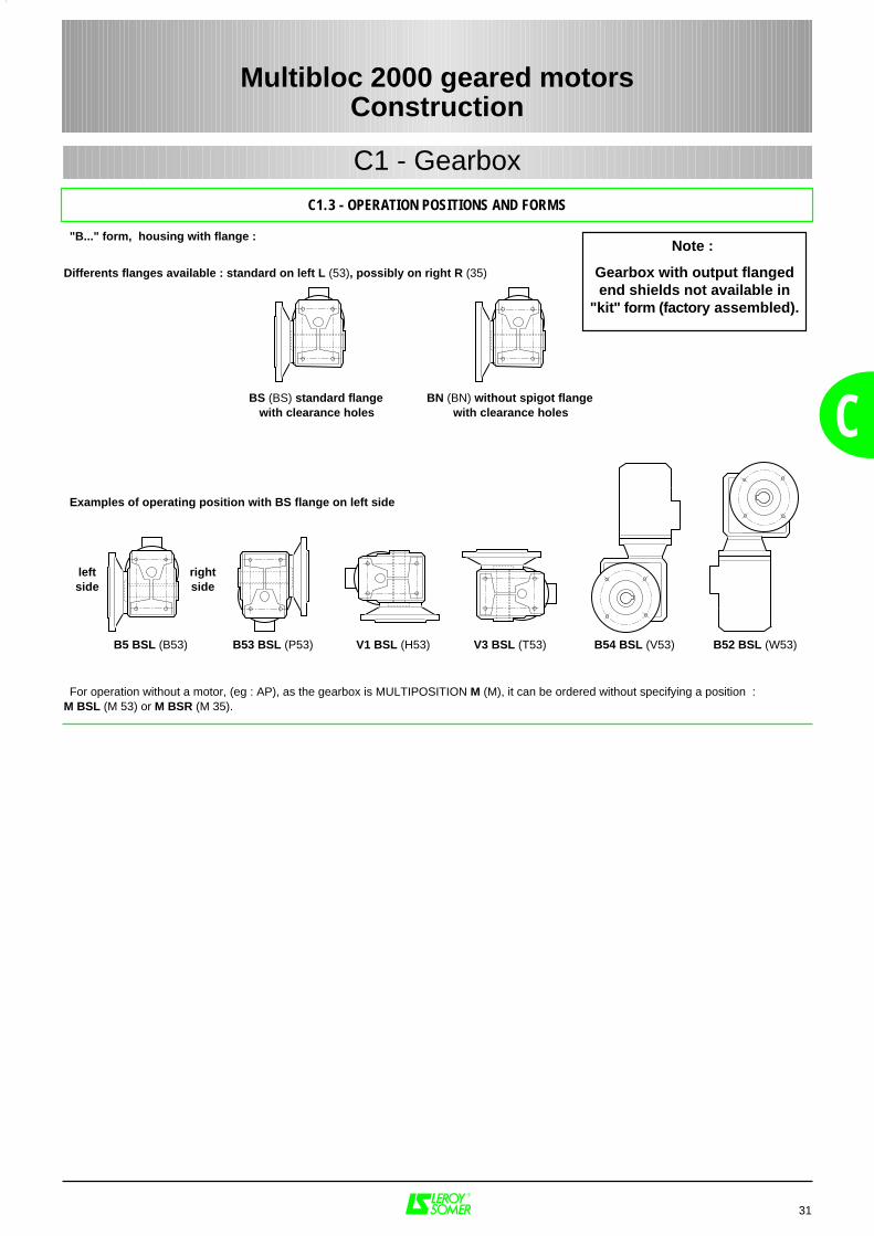
"B..." form, housing with flange :
Differents flanges available : standard on left L (53), possibly on right R (35)
BS (BS) standard flange BN (BN) without spigot flangewith clearance holes with clearance holes
Examples of operating position with BS flange on left side
haut
B5 BSL (B53) B53 BSL (P53) V1 BSL (H53) V3 BSL (T53) B54 BSL (V53) B52 BSL (W53)
For operation without a motor, (eg : AP), as the gearbox is MULTIPOSITION M (M), it can be ordered without specifying a position :M BSL (M 53) or M BSR (M 35).
Multibloc 2000 geared motorsConstruction
C1.3 - OPERATION POSITIONS AND FORMS
C1 - Gearbox
rightside
leftside
Note :
Gearbox with output flangedend shields not available in
"kit" form (factory assembled).
32
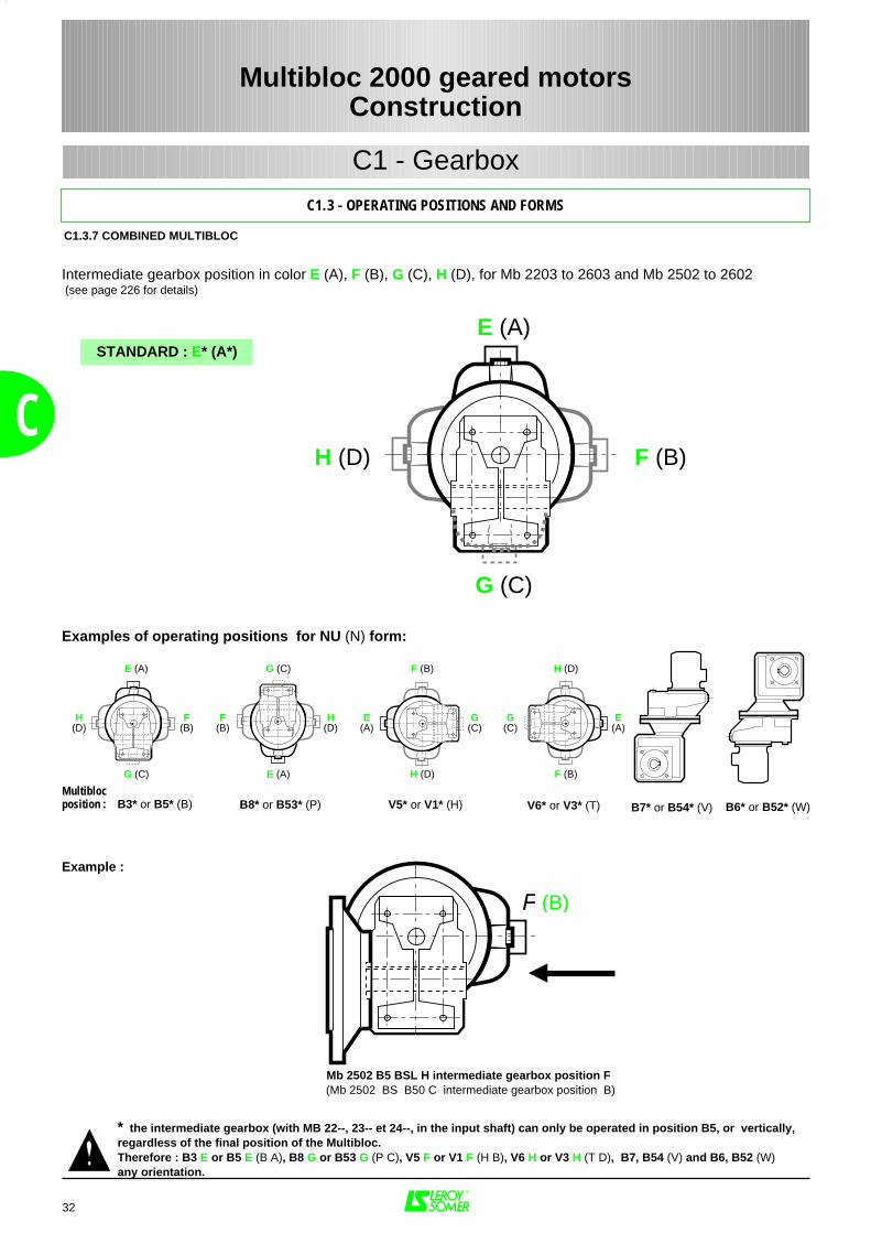
Examples of operating positions for NU (N) form:
Multiblocposition :
Example :
Mb 2502 B5 BSL H intermediate gearbox position F (Mb 2502 BS B50 C intermediate gearbox position B)
* the intermediate gearbox (with MB 22--, 23-- et 24--, in the input shaft) can only be operated in position B5, or vertically,regardless of the final position of the Multibloc.Therefore : B3 E or B5 E (B A), B8 G or B53 G (P C), V5 F or V1 F (H B), V6 H or V3 H (T D), B7, B54 (V) and B6, B52 (W)any orientation.
B3* or B5* (B) B8* or B53* (P) B7* or B54* (V) B6* or B52* (W)
Intermediate gearbox position in color E (A), F (B), G (C), H (D), for Mb 2203 to 2603 and Mb 2502 to 2602 (see page 226 for details)
STANDARD : E* (A*)
F
Multibloc 2000 geared motorsConstruction
C1 - Gearbox
C
C1.3 - OPERATING POSITIONS AND FORMS
C1.3.7 COMBINED MULTIBLOC
(B)
V5* or V1* (H) V6* or V3* (T)
G (C)
E (A)
H (D) F (B)
H(D)
E (A)
G (C)
G (C)
E (A)
F(B)
F(B)
H(D)
F (B)
H (D)
E(A)
G(C)
H (D)
F (B)
G(C)
E(A)

33
C
C2 - Applications
C2.1 - GENERAL
Multibloc 2000 geared motorsConstruction
FLYING LEADSAccording to specification, motors canbe supplied with flying leads or with theleads in multicore cables. Please statecable characteristics (type and supplier,cross-section, length, number of conduc-tors), method of connection (on statorwinding ends, or on a separate panel),and the cable gland position required.
Terminal box for LS 71 motor withoutbrake
Terminal box for brake motors FCR, FCO, FAP2 (up to 132 frame size)
Positions of the cable glandin relation to the drive end
Positions of the terminal boxin relation to the front view of the gearbox
(IM B5 or B14 motor behind)Standard position on delivery : A
13 Standardpositionon delivery
A
B
C
D
C2.1.1 MAINS CONNECTION
MOTOR TERMINAL BOXPlaced as standard on the top of the motor(position A) and at the front, the terminal boxhas IP 55 protection and is fitted with one ortwo cable glands (see table on opposite page).
For motors with flange and on special request,the position of the terminal box can be modified(on the right B, C underneath, or on the left D,viewing gearbox from the front).
The standard position of the cable glandis on the right, seen from the drive end.Any other possibilities must be specifiedon ordering, after acceptance.
Terminal box for LS 80 to 132 motorswithout brake
Terminal box for LS 71 to 90 FAST brakemotor
Cable gland type Min cable Ø (mm) Max cable Ø (mm)
PE 9 5 8
PE 11 7 10
PE 16 10 14
PE 21 12 18
PE 29 16 24
PE 36 22 30
PE 42 27 35
PE 48 31 40
34
CD.O.L. starting Y∆ starting 2 windings 1 winding
56 Plastic PE 11 - 2 x PE 11 PE 11 PE 9
63 Plastic PE 11 - 2 x PE 11 PE 11 PE 9
71 Aluminium alloy PE 11 - 2 x PE 11 PE 11 PE 9
80 Aluminium alloy PE 16 - 2 x PE 16 PE 16 PE 9
90 Aluminium alloy PE 16 - 2 x PE 16 PE 16 PE 9
100 Aluminium alloy PE 16* 2 x PE 16* 2 x PE 16* PE 16* PE 9
112 / 132 S Aluminium alloy PE 16* 2 x PE 16* 2 x PE 16* PE 16* PE 9
132 M Aluminium alloy PE 21 2 x PE 21 2 x PE 21 PE 21* PE 9
160 Aluminium alloy 2 x PE 21 2 x PE 21 2 x PE 21 2 x PE 21 PE 11
180 Aluminium alloy2 - 4p 2 x PE 296 - 8p 2 x PE 21 2 x PE 21 2 x PE 29 2 x PE 29 PE 11
200 Aluminium alloy 2 x PE 292 - 6 - 8p 2 x PE 294 - 6p 2 x PE 21 2 x PE 36 2 x PE 36 PE 11
225 Aluminium alloy2 - 4p 2 x PE 366 - 8p 2 x PE 29 2 x PE 29 2 x PE 36 2 x PE 36 PE 11
250 Aluminium alloy2 - 4 - 6p 2 x PE 36
8p 2 x PE 29 2 x PE 29 2 x PE 42 2 x PE 42 PE 11
280 Aluminium alloy2 - 4p 2 x PE 426 - 8p 2 x PE 36
2 - 4p 2 x PE 366 - 8p 2 x PE 29 2 x PE 42 2 x PE 42 PE 11
315 Aluminium alloy2 - 4p 2 x PE 486 - 8p 2 x PE 36
2 - 4p 2 x PE 486 - 8p 2 x PE 36 2 x PE 48 2 x PE 48 PE 11
C2.1 - GENERAL
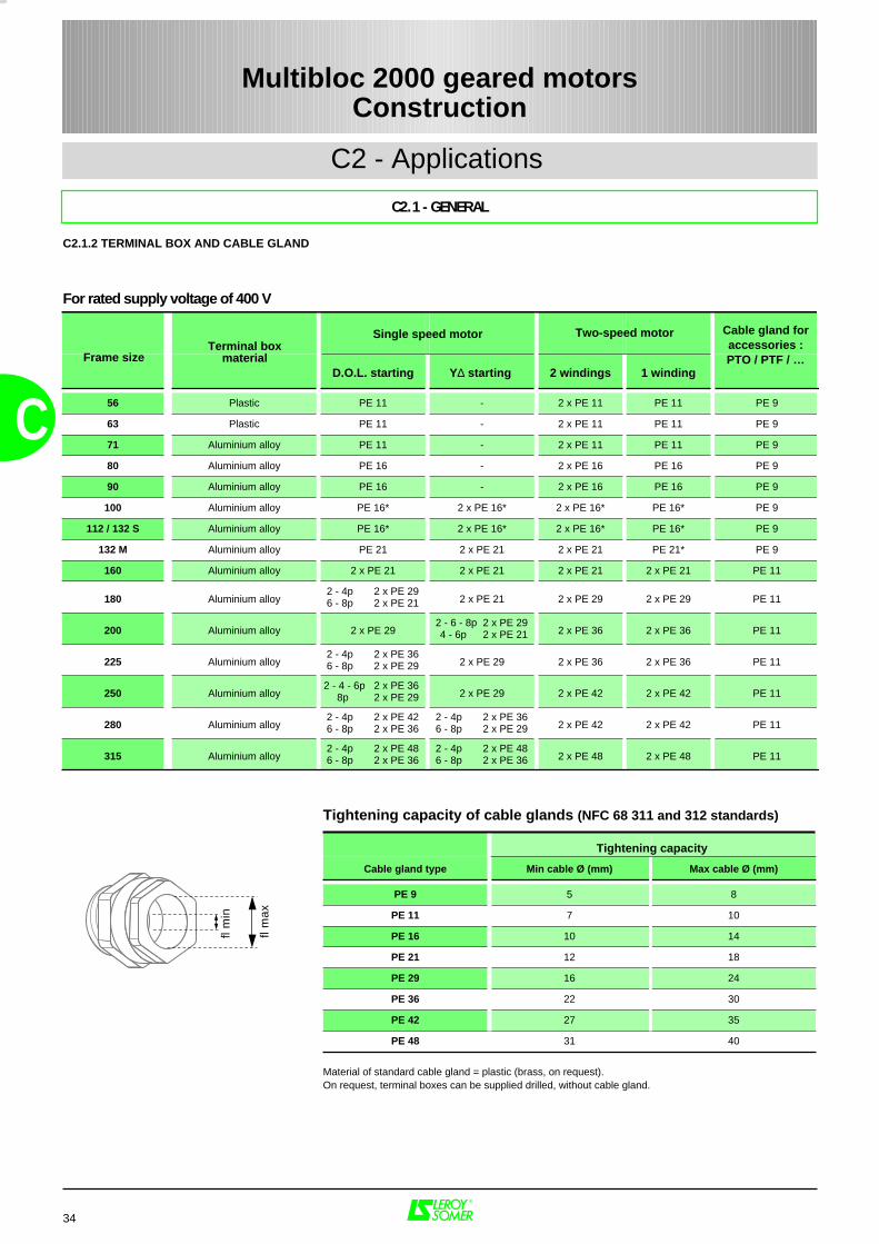
Tightening capacity of cable glands (NFC 68 311 and 312 standards)
fl m
in
fl m
ax
Tightening capacity
Material of standard cable gland = plastic (brass, on request).On request, terminal boxes can be supplied drilled, without cable gland.
C2 - Applications
Multibloc 2000 geared motorsConstruction
C2.1.2 TERMINAL BOX AND CABLE GLAND
For rated supply voltage of 400 V
Two-speed motor Cable gland foraccessories :PTO / PTF / …
Terminal boxmaterialFrame size
Single speed motor
LSMV 3-PHASE MOTOR1 SPEED - 2 VOLTAGES
L1 - L2 - L3
W2
T1 T2 T1 T2
U2 V2
L1 L2 L3
U1 V1 W1
W2 U2 V2
L1 L2 L3
U1 V1 W1
35
C
C2.1 - GENERAL
C2 - Applications
Multibloc 2000 geared motorsConstruction
3-PHASE MOTOR 1 SPEED - 2 VOLTAGES
L1 - L2 - L3 L2 - L1 - L3
W2 U2 V2
L1 L2 L3
U1 V1 W1
W2 U2 V2
L1 L2 L3
U1 V1 W1
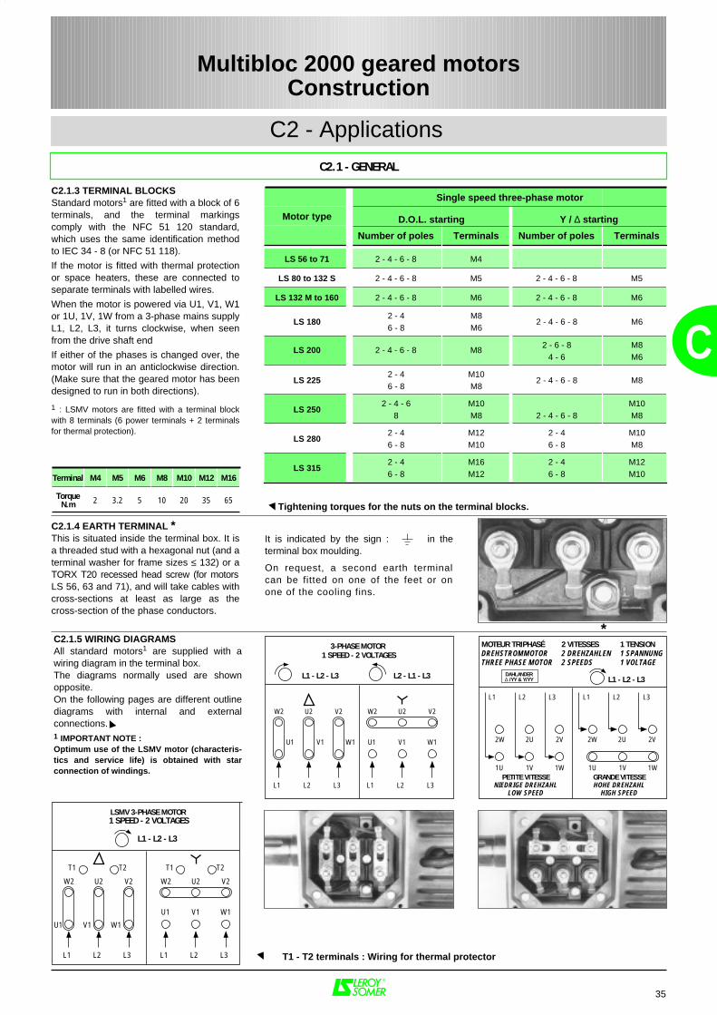
C2.1.5 WIRING DIAGRAMSAll standard motors1 are supplied with awiring diagram in the terminal box.The diagrams normally used are shownopposite.On the following pages are different outlinediagrams with internal and externalconnections.1 IMPORTANT NOTE :Optimum use of the LSMV motor (characteris-tics and service life) is obtained with starconnection of windings.
C2.1.3 TERMINAL BLOCKSStandard motors1 are fitted with a block of 6terminals, and the terminal markingscomply with the NFC 51 120 standard,which uses the same identification methodto IEC 34 - 8 (or NFC 51 118).
If the motor is fitted with thermal protectionor space heaters, these are connected toseparate terminals with labelled wires.
When the motor is powered via U1, V1, W1or 1U, 1V, 1W from a 3-phase mains supplyL1, L2, L3, it turns clockwise, when seenfrom the drive shaft end
If either of the phases is changed over, themotor will run in an anticlockwise direction.(Make sure that the geared motor has beendesigned to run in both directions).
1 : LSMV motors are fitted with a terminal blockwith 8 terminals (6 power terminals + 2 terminalsfor thermal protection).
Motor type
Number of poles Terminals Number of poles Terminals
LS 56 to 71 2 - 4 - 6 - 8 M4
LS 80 to 132 S 2 - 4 - 6 - 8 M5 2 - 4 - 6 - 8 M5
LS 132 M to 160 2 - 4 - 6 - 8 M6 2 - 4 - 6 - 8 M6
LS 1802 - 46 - 8
M8M6
2 - 4 - 6 - 8 M6
LS 200 2 - 4 - 6 - 8 M82 - 6 - 8
4 - 6M8M6
LS 2252 - 46 - 8
M10M8
2 - 4 - 6 - 8 M8
LS 2502 - 4 - 6
8M10M8 2 - 4 - 6 - 8
M10M8
LS 2802 - 46 - 8
M12M10
2 - 46 - 8
M10M8
LS 3152 - 46 - 8
M16M12
2 - 46 - 8
M12M10Terminal M4 M5 M6 M8 M10 M12 M16
TorqueN.m 2 3.2 5 10 20 35 65
C2.1.4 EARTH TERMINAL *This is situated inside the terminal box. It isa threaded stud with a hexagonal nut (and aterminal washer for frame sizes ≤ 132) or aTORX T20 recessed head screw (for motorsLS 56, 63 and 71), and will take cables withcross-sections at least as large as thecross-section of the phase conductors.
It is indicated by the sign : in theterminal box moulding.
On request, a second earth terminalcan be fitted on one of the feet or onone of the cooling fins.
L1 - L2 - L3
MOTEUR TRIPHASÉDREHSTROMMOTORTHREE PHASE MOTOR
2 VITESSES2 DREHZAHLEN2 SPEEDS
1 TENSION1 SPANNUNG1 VOLTAGE
PETITE VITESSENIEDRIGE DREHZAHL
LOW SPEED
2W 2U 2V
L1 L2 L3
1U 1V 1WGRANDE VITESSEHOHE DREHZAHL
HIGH SPEED
DAHLANDER∆ /YY & Y/YY
2W 2U 2V
L1 L2 L3
1U 1V 1W
Tightening torques for the nuts on the terminal blocks.
*
T1 - T2 terminals : Wiring for thermal protector
Single speed three-phase motor
D.O.L. starting Y / ∆ starting
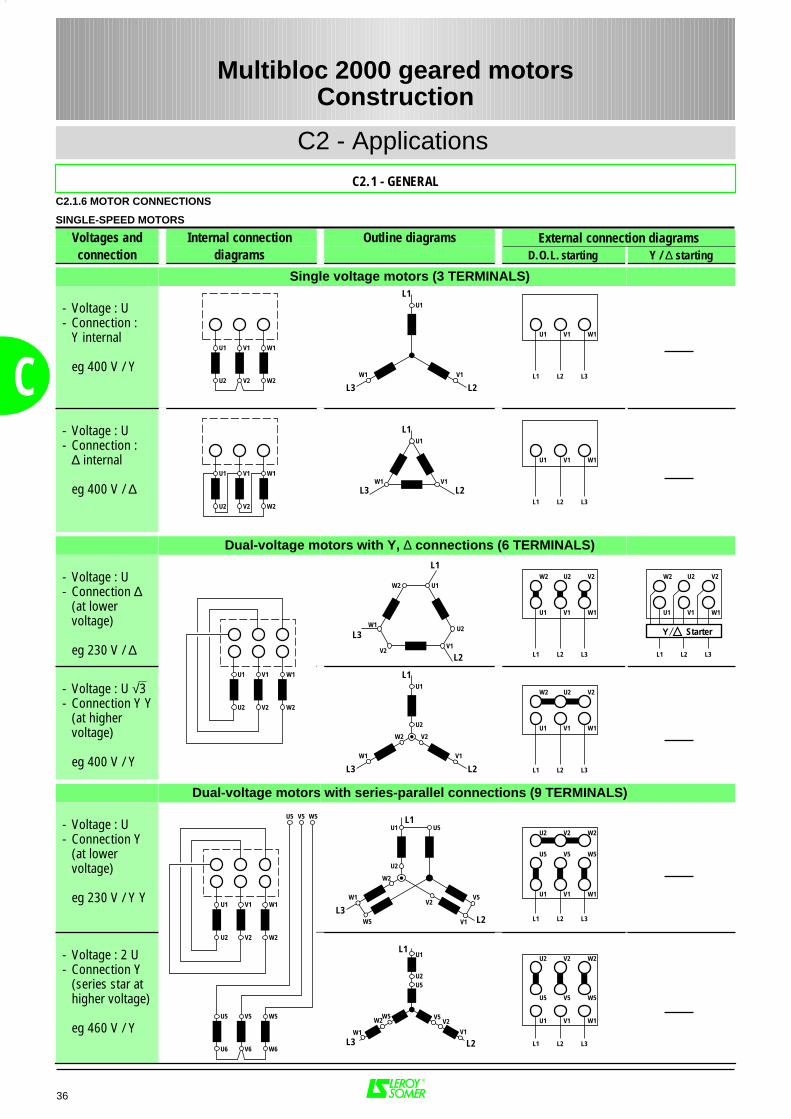
U1 V1
W1U2 V2 W2
U1
V1
L1
L3 L2L3L2L1
W1V1U1
U1 V1W1
U2 V2 W2
U1
V1
L1
L3 L2L3L2L1
W1V1U1
W1
W1
U1 V1
U2 V2 W2
W1
U1 V1
U2 V2 W2
W1
U5 V5
U6 V6 W6
W5
U5 V5 W5
W1
U1
U2
L1
L3
L2 L3L2L1
W1V1U1
L3L2L1
W1V1U1
W1
U1
V2
L1
L3 L2
U2
W2
V1
V2U2W2 V2U2W2
W1
U1
L3
U2
W2
V2
W5
U5
V1
L1
L2
V5
W1
U1
V1
L1
L3 L2
U2U5
W5W2 V2
V5
W2
V2V1
L3L2L1
W1V1U1
W5V5U5
L3L2L1
W1V1U1
V2U2W2
L3L2L1
W1V1U1
W2 V2U2
W5V5U5
W2 V2U2
Y Starter
C2.1.6 MOTOR CONNECTIONS
SINGLE-SPEED MOTORS
Voltages and Internal connection Outline diagramsconnection diagrams D.O.L. starting Y / ∆ starting
Single voltage motors (3 TERMINALS)
- Voltage : U - Connection :
Y internal
eg 400 V / Y
- Voltage : U - Connection :
∆ internal
eg 400 V / ∆
Dual-voltage motors with Y, ∆ connections (6 TERMINALS)
- Voltage : U - Connection ∆
(at lower voltage)
eg 230 V / ∆
- Voltage : U √3 - Connection Y Y
(at highervoltage)
eg 400 V / Y
Dual-voltage motors with series-parallel connections (9 TERMINALS)
- Voltage : U - Connection Y
(at lowervoltage)
eg 230 V / Y Y
- Voltage : 2 U - Connection Y
(series star at higher voltage)
eg 460 V / Y
36
External connection diagrams
C
C2 - Applications
C2.1 - GENERAL
Multibloc 2000 geared motorsConstruction
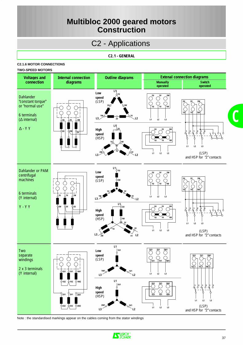
37
C
C2 - Applications
C2.1 - GENERAL
Multibloc 2000 geared motorsConstruction
C2.1.6 MOTOR CONNECTIONS
TWO-SPEED MOTORS
Voltages and Internal connection Outline dIagramsconnection diagrams Manually
operatedSwitch
operated
Dahlander"constant torque" or "normal use"
6 terminals(∆ internal)
∆ - Y Y
Dahlander or PAMcentrifugal machines
6 terminals(Y internal)
Y - Y Y
Twoseparate windings
2 x 3 terminals(Y internal)
Note : the standardised markings appear on the cables coming from the stator windings
L3L2L1
1W1V1U
1W
2U
1V
L1
L3 L21U 1V
2U 2W 2V
1W
1U1 1V1
1U2 1V2 1W2
1W1
2U1 2V1
2U2 2V2 2W2
2W1
1W1
1U1
L1
L3 L21V1
L3
1W
1U
1V
2W
2U
V1
L1
L2
2V
2W
1U
2V
2W2V2U
2W
1W
L3
2U
1V
L1
1U
2VL2
L3L2L1
1W1V1U
2W2V2U
L3L2L1
1W1V1U
2W2V2U
1 2 1 2 1 2
1U 1V
2W 2V
1W
2U
1W
1U
1V
L1
L3 L2
2W
2U 2V
2W1
2U1
L1
L3 L22V1
L3L2L1
1W1V1U
2W2V2U
L3L2L1
1W1V1U
2W2V2U
L3L2L1
1W1V1U
2W2V2U
1 2 1 2 1 2
L3L2L1
1W11V11U1
2W12V12U1
L3L2L1
1W11V11U1
2W12V12U1
L3L2L1
1W 11V 11U 1
2W12V12U1
1 2 1 2 1 2
Lowspeed(LSP)
Highspeed(HSP)
Lowspeed(LSP)
Highspeed(HSP)
Lowspeed(LSP)
Highspeed(HSP)
(LSP)and HSP for "2" contacts
(LSP)and HSP for "2" contacts
(LSP)and HSP for "2" contacts
Extenal connection diagrams
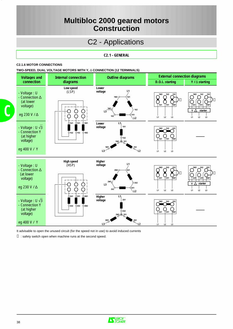
C2.1.6 MOTOR CONNECTIONS
TWO-SPEED, DUAL VOLTAGE MOTORS WITH Y, ∆ CONNECTION (12 TERMINALS)
Voltages and Internal connection Outline diagramsconnection diagrams D.O.L. starting Y / ∆ starting
- Voltage : U - Connection ∆ (at lower voltage)
eg 230 V / ∆
- Voltage : U √3 - Connection Y (at higher voltage)
eg 400 V / Y
- Voltage : U - Connection ∆ (at lower voltage)
eg 230 V / ∆
- Voltage : U √3 - Connection Y (at higher voltage)
eg 400 V / Y
1U1 1V1
1U2 1V2 1W2
1W1
1W1
1U1
1U2
L1
L3
L2 L3L2L1
1W11V11U1
L3L2L1
1W11V11U1
1W1
1U1
1V1
L1
L3 L2
1U2
1W2
1V2
1V21U21W2 1V21U21W21W2
1V21V1
L3L2L1
1W11V11U1
1V21U21W2
2U1 2V1
2U2 2V2 2W2
2W1
2W1
2U1
2U2
L1
L3
L2 L3L2L1
2W12V12U1
L3L2L1
2W12V12U1
2W1
2U1
2V1
L1
L3 L2
2U2
2W2
2V2
2V22U22W2 2V22U22W22W2
2V22V1
L3L2L1
2W12V12U1
2V22U22W2
➊
➊
➊
➊
Y
starter
starter
Y
38
C
It advisable to open the unused circuit (for the speed not in use) to avoid induced currents
➊ : safety switch open when machine runs at the second speed.
External connection diagrams
Multibloc 2000 geared motorsConstruction
C2 - Applications
C2.1 - GENERAL
Highervoltage
Highervoltage
High speed(HSP)
Lower voltage
Lower voltage
Low speed(LSP)
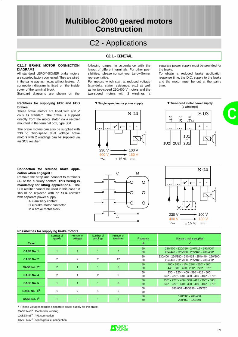
39
C
C2.1 - GENERAL
C2 - Applications
Multibloc 2000 geared motorsConstruction
C2.1.7 BRAKE MOTOR CONNECTIONDIAGRAMSAll standard LEROY-SOMER brake motorsare supplied factory connected. They are wiredin the same way as motors without brakes. Aconnection diagram is fixed on the insidecover of the terminal block.Standard diagrams are shown on the
separate power supply must be provided forthe brake. To obtain a reduced brake applicationresponse time, the D.C. supply to the brakeand the motor must be cut at the sametime.
following pages, in accordance with thelayout of different terminals. For other pos-sibilities, please consult your Leroy-Somerrepresentative.For motors which start at reduced voltage(star-delta, stator resistance, etc.) as wellas for two-speed 230/400 V motors and thetwo-speed motors with 2 windings, a
Possibilities for supplying brake motorsNumber of
speedsNumber ofvoltages
Number ofwindings
Number ofterminals Frequency Standard mains supplies
Case Hz V
CASE No. 1 1 2 1 65060
230/400 - 220/380 - 240/415 - 290/500*254/440 - 220/380 - 265/460 - 280/480*
CASE No. 2 2 2 2 125060
230/400 - 220/380 - 240/415 - 254/440 - 290/500*254/440 - 220/380 - 265/460 - 280/480*
CASE No. 3a 2 1 1 65060
400 - 380 - 415 - 230* - 220* - 500*440 - 380 - 460 - 230* - 220* - 575*
CASE No. 4 2 1 2 65060
230* - 220* - 400 - 380 - 415 - 500*230* - 220* - 440 - 380 - 460 - 480* - 575*
CASE No. 5 1 1 1 35060
230* - 220* - 400 - 380 - 415 - 200* - 500*230* - 220* - 440 - 380 - 460 - 480* - 575*
CASE No. 6b 1 2 1 65060
380/660 - 400/690 - 415/720-
CASE No. 7c 1 2 1 95060
190/380 - 200/400230/460 - 220/440
* : These voltages require a separate power supply for the brake.
CASE No3a : Dahlander winding
CASE No6b : Y/∆ connection
CASE No7c : series/parallel connection
Rectifiers for supplying FCR and FCObrakesThese brake motors are fitted with 400 Vcoils as standard. The brake is supplieddirectly from the motor stator via a rectifiermounted in the terminal box, type S04.
The brake motors can also be supplied with230 V. Two-speed dual voltage brakemotors with 2 windings can be supplied viaan SO3 rectifier.
+ -
230 V 100 V400 V 180 V ± 15 %
S 04
+
+
-
21U
1
2U2
1U2
1U2 2U2 2U1
1U1
S 03
MC
A
Connection for reduced brake appli-cation when engaged :Remove the strap and connect to terminals(A) of the auxiliary contact. This wiring ismandatory for lifting applications. TheS03 rectifier cannot be used in this case : itshould be replaced with an SO4 rectifierwith separate power supply.
A = auxiliary contactC = brake motor contactorM = brake motor block
+ -
(A)
S 04
230 V 100 V400 V 180 V ± 15 %
Single speed motor power supply Two-speed motor power supply(2 windings)
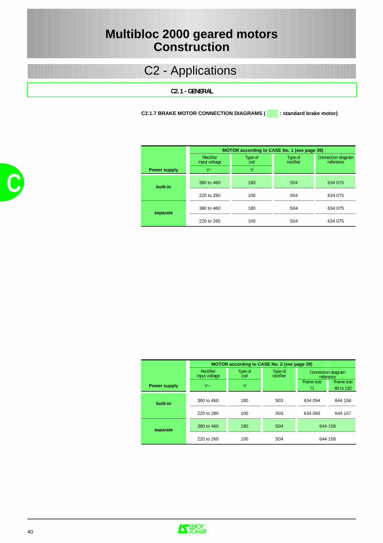
C2 - Applications
40
C
C2.1 - GENERAL
C2.1.7 BRAKE MOTOR CONNECTION DIAGRAMS ( : standard brake motor)
MOTOR according to CASE No. 1 (see page 39)
Rectifierinput voltage
Type ofcoil
Type ofrectifier
Connection diagramreference
Power supply V~ V
380 to 460 180 S04 634 075
220 to 280 100 S04 634 075
380 to 460 180 S04 634 075
220 to 265 100 S04 634 075
built-in
MOTOR according to CASE No. 2 (see page 39)
Rectifierinput voltage
Type ofcoil
Type ofrectifier
Power supply V~ VFrame size
71Frame size80 to 132
380 to 460 180 S03 634 094 644 156
220 to 280 100 S03 634 093 644 157
380 to 460 180 S04 644 158
220 to 265 100 S04 644 158
built-in
Multibloc 2000 geared motorsConstruction
separate
separate
Connection diagramreference
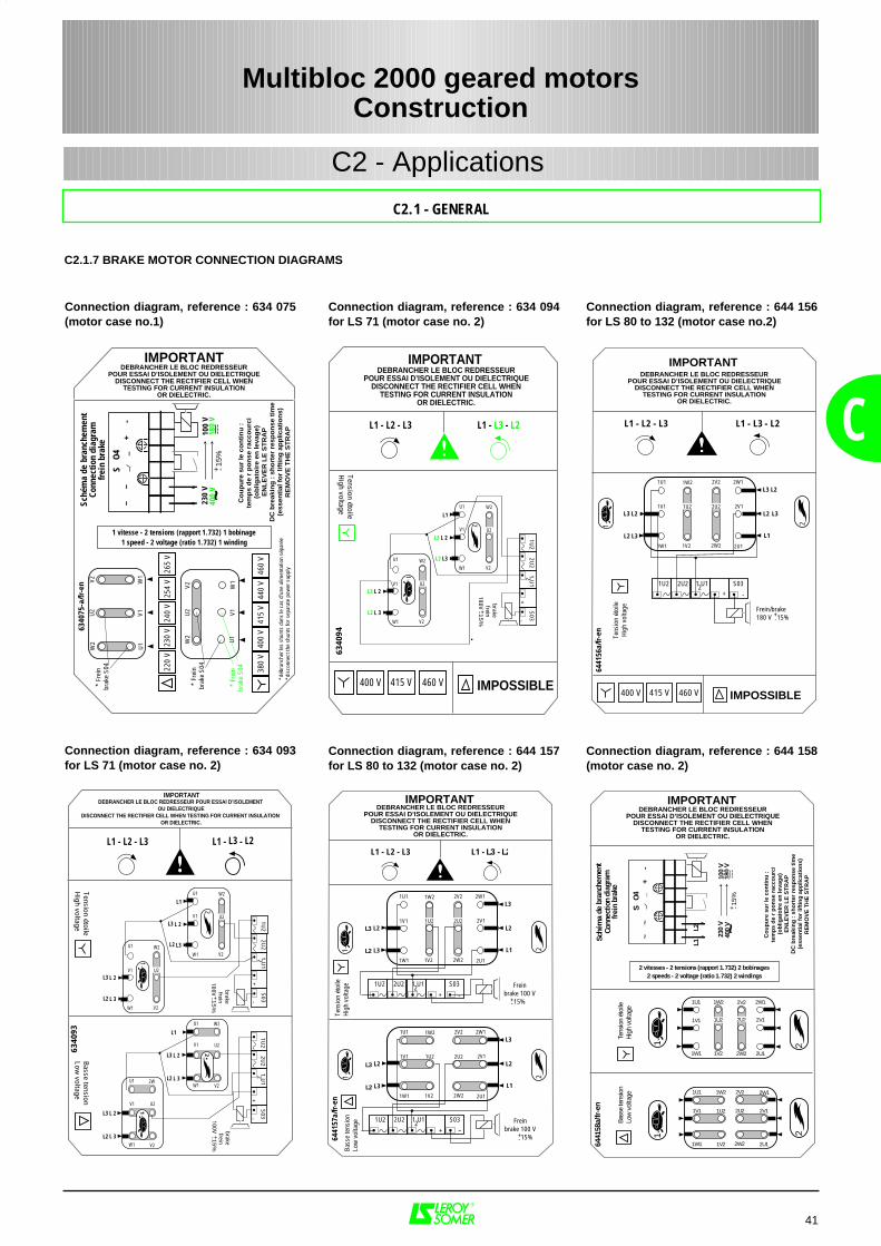
L3
L2
L3
L2
L3
L2
L3
L2
L3 L2
2V2
2W2
1U1
1V1
1W1
2W1
2V1
2U1
1W2
1V2
11 2
2
Sché
ma
de b
ranc
hem
ent
Conn
ectio
n di
agra
mfre
in b
rake
S O
4~
~_
+-
DEBRANCHER LE BLOC REDRESSEURPOUR ESSAI D’ISOLEMENT OU DIELECTRIQUE
DISCONNECT THE RECTIFIER CELL WHENTESTING FOR CURRENT INSULATION
OR DIELECTRIC.
6441
58a/
fr-en
IMPORTANT
2 vitesses - 2 tensions (rapport 1.732) 2 bobinages2 speeds - 2 voltage (ratio 1.732) 2 windings
2W1
2V1
2U1
1W21U1
1U21V1
1V21W1
2V2
2U2
2W2
1U2 2U2
230
V40
0 V ~
100
V18
0 V
Co
up
ure
su
r le
co
nti
nu
:
tem
ps
de
rp
on
se r
acco
urc
i(o
blig
ato
ire
en le
vag
e)E
NL
EV
ER
LE
ST
RA
PD
C b
reak
ing
: s
ho
rter
res
po
nse
tim
e(e
ssen
tial
fo
r lif
tin
g a
pp
licat
ion
s)R
EM
OV
E T
HE
ST
RA
P
+ -15%
Tens
ion
étoi
leHi
gh v
olta
geBa
sse
tens
ion
Low
vol
tage
L1L2
DEBRANCHER LE BLOC REDRESSEURPOUR ESSAI D’ISOLEMENT OU DIELECTRIQUE
DISCONNECT THE RECTIFIER CELL WHENTESTING FOR CURRENT INSULATION
OR DIELECTRIC.
6441
57a/
fr-en
IMPORTANT
11
22
2V2
2W2
1U1
1V1
1W1
2W1
2V1
2U1
1W2
1V2
1U2 2U2
L1
L2
L3
L2
L3
1U2 2U2 1 U1 S03
+ -2 Frein
brake 100 V15%
2V2
2W2
1U1
1V1
1W1
2W1
2V1
2U1
1W2
1V2
1U2 2U2
L1
L2
L3
L2
L3
1U2 2U2 1 U1 S03
+ -2 Frein
brake 100 V 15%
Tens
ion
étoi
leHi
gh v
olta
geBa
sse
tens
ion
Low
vol
tage
L1 - L2 - L3 L1 - -
+-
+-
L3
L3
L2
L2
L3
L2
L2
L3
L3 L2
DEBRANCHER LE BLOC REDRESSEUR POUR ESSAI D’ISOLEMENT OU DIELECTRIQUE
DISCONNECT THE RECTIFIER CELL WHEN TESTING FOR CURRENT INSULATION OR DIELECTRIC.
6340
93
IMPORTANT
1
2
U1
V1
W1
W2
V2
U2
L1
L 2
L1
L 2
L 3
L3
1U2
2U2
1 U1
S03
+-
2
brake frein
U1
V1
W1
W2
V2
U2 L 2
L 3
W1 V2
V1 U2
U1 W2
L 3
L 2
W1 V2
V1
U2
U1
V1
2W
1U2
2U2
1 U1
S03
+-
2
1
2
Tension étoileH
igh voltageB
asse tension Low
voltage
L1 - L2 - L3 L1 - -
+- 15
%
brake frein+- 1
5%
100V100V
L3 L2
L3
L2
L3
L2
DEBRANCHER LE BLOC REDRESSEURPOUR ESSAI D’ISOLEMENT OU DIELECTRIQUE
DISCONNECT THE RECTIFIER CELL WHENTESTING FOR CURRENT INSULATION
OR DIELECTRIC.
6441
56a/
fr-en
IMPORTANT
L1 - L2 - L3 L1 - -
1 2
400 V 415 V 460 V
2V2
2W2
1U1
1V1
1W1
2W1
2V1
2U1
1W2
1V2
1U2 2U2
L1
L2
L3
L2
L3
1U2 2U2 1 U1 S03+ -
2
Frein/brake 180 V
Tens
ion
étoi
leHi
gh v
olta
ge
IMPOSSIBLE
+-15%
230
V ~10
0 V
DEBRANCHER LE BLOC REDRESSEURPOUR ESSAI D’ISOLEMENT OU DIELECTRIQUE
DISCONNECT THE RECTIFIER CELL WHENTESTING FOR CURRENT INSULATION
OR DIELECTRIC.
6340
75-a
/fr-e
n
IMPORTANT
1 vitesse - 2 tensions (rapport 1.732) 1 bobinage1 speed - 2 voltage (ratio 1.732) 1 winding
W2
U2
V2
W2
U1
U2
V1
V2 W1
U1
V1W
1
S O
4~
~_
+-
220
V23
0 V
240
V25
4 V
380
V40
0 V
415
V44
0 V
265
V
460
V
* Fr
ein
bra
ke S
04
* Fr
ein
bra
ke S
04
*déb
ranc
her l
es s
hunt
s da
ns le
cas
d'u
ne a
limen
tatio
n sé
paré
e*d
isco
nnec
t the
shu
nts
for s
epar
ate
pow
er s
uppl
y
Sché
ma
de b
ranc
hem
ent
Conn
ectio
n di
agra
mfr
ein
brak
e
Co
up
ure
su
r le
co
nti
nu
:
tem
ps
de
rp
on
se r
acco
urc
i(o
blig
ato
ire
en le
vag
e)E
NL
EV
ER
LE
ST
RA
PD
C b
reak
ing
: s
ho
rter
res
po
nse
tim
e(e
ssen
tial
fo
r lif
tin
g a
pp
licat
ion
s)R
EM
OV
E T
HE
ST
RA
P
+ -15%
400
V 18
0 V
* Fr
ein
brak
e S0
4
1
2
U1
V1
W1
W2
V2
U2
L1
L 2
L3
1U2
2U2
1 U1
S03
+-
2
brake frein
U1
V1
W1
W2
V2
U2 L 2
L 3
Tension étoileH
igh voltage
L1 - L2 - L3 L1 - -
+- 15
%180V
400 V 415 V 460 V IMPOSSIBLE
6340
94
DEBRANCHER LE BLOC REDRESSEURPOUR ESSAI D’ISOLEMENT OU DIELECTRIQUE
DISCONNECT THE RECTIFIER CELL WHENTESTING FOR CURRENT INSULATION
OR DIELECTRIC.
IMPORTANT
L3
L2
L3
L2
L3 L2
41
C
C2.1 - GENERAL
C2.1.7 BRAKE MOTOR CONNECTION DIAGRAMS
Connection diagram, reference : 634 075(motor case no.1)
Multibloc 2000 geared motorsConstruction
C2 - Applications
Connection diagram, reference : 634 093for LS 71 (motor case no. 2)
Connection diagram, reference : 634 094for LS 71 (motor case no. 2)
Connection diagram, reference : 644 156for LS 80 to 132 (motor case no.2)
Connection diagram, reference : 644 157for LS 80 to 132 (motor case no. 2)
Connection diagram, reference : 644 158(motor case no. 2)
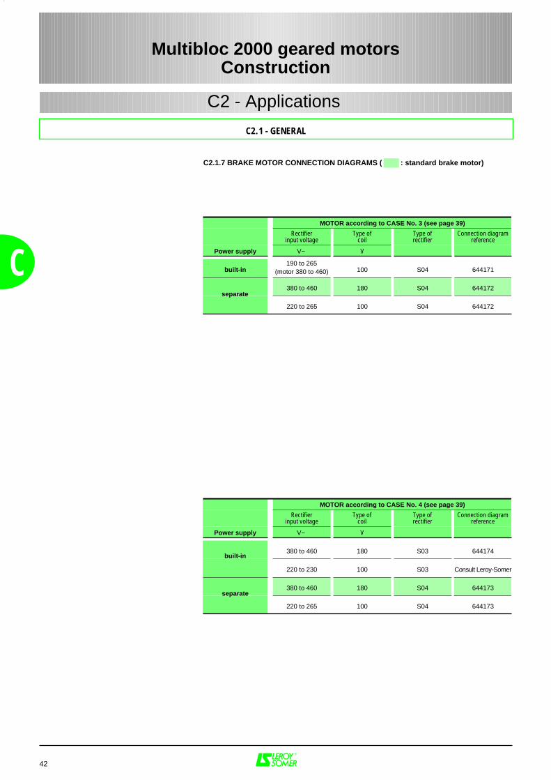
42
C
C2.1 - GENERAL
C2.1.7 BRAKE MOTOR CONNECTION DIAGRAMS ( : standard brake motor)
Multibloc 2000 geared motorsConstruction
C2 - Applications
MOTOR according to CASE No. 3 (see page 39)
Rectifierinput voltage
Type ofcoil
Type ofrectifier
Connection diagramreference
Power supply V~ V
built-in190 to 265
(motor 380 to 460) 100 S04 644171
380 to 460 180 S04 644172
220 to 265 100 S04 644172
MOTOR according to CASE No. 4 (see page 39)
Rectifierinput voltage
Type ofcoil
Type ofrectifier
Connection diagramreference
Power supply V~ V
380 to 460 180 S03 644174
220 to 230 100 S03 Consult Leroy-Somer
380 to 460 180 S04 644173
220 to 265 100 S04 644173
built-in
separate
separate
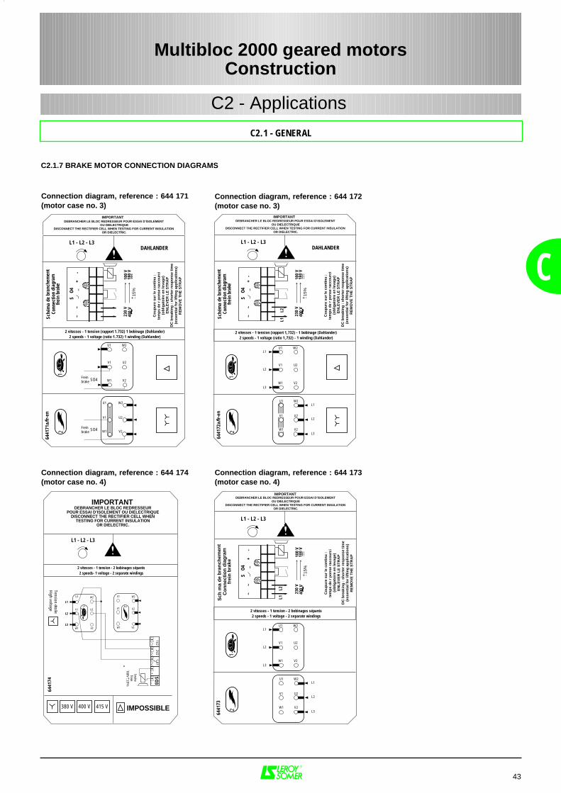
U1
V1
W1
12
Sch
ma
de
bra
nch
emen
tC
on
nec
tio
n d
iag
ram
frei
n b
rake
S O
4~
~_
+-
6441
73
2 vitesses - 1 tension - 2 bobinages séparés2 speeds - 1 voltage - 2 separate windings
230
V40
0 V ~
100
V18
0 V
Co
up
ure
su
r le
co
nti
nu
:
tem
ps
de
rp
on
se r
acco
urc
i(o
blig
ato
ire
en le
vag
e)E
NL
EV
ER
LE
ST
RA
PD
C b
reak
ing
: s
ho
rter
res
po
nse
tim
e(e
ssen
tial
fo
r lif
tin
g a
pp
licat
ion
s)R
EM
OV
E T
HE
ST
RA
P
+ -15%
W2L1
L1
L2
L3
L2
L3
U2
V2
DEBRANCHER LE BLOC REDRESSEUR POUR ESSAI D’ISOLEMENT OU DIELECTRIQUE
DISCONNECT THE RECTIFIER CELL WHEN TESTING FOR CURRENT INSULATION OR DIELECTRIC.
L1 - L2 - L3
W2
U2
V2
U1
W1
V1
IMPORTANT
L1L2
1 2
U1
V1
W2
V2W1
U2
1U2
2U2
1 U1
+-
2
brake frein
U1
V1
W1
W2
V2
U2L2
Tension étoileH
igh voltage
L1 - L2 - L3
L3
L1
+- 15%
180V
380 V 400 V 415 V IMPOSSIBLE
6441
74
2 vitesses - 1 tension - 2 bobinages séparés2 speeds- 1 voltage - 2 separate windings
DEBRANCHER LE BLOC REDRESSEURPOUR ESSAI D’ISOLEMENT OU DIELECTRIQUE
DISCONNECT THE RECTIFIER CELL WHENTESTING FOR CURRENT INSULATION
OR DIELECTRIC.
IMPORTANT
SO3
U1
V1
W1
12
Sché
ma
de b
ranc
hem
ent
Conn
ectio
n di
agra
mfre
in b
rake
S O
4~
~_
+-
6441
72a/
fr-en
2 vitesses - 1 tension (rapport 1,732) - 1 bobinage (Dahlander)2 speeds - 1 voltage (ratio 1,732) - 1 winding (Dahlander)
230
V40
0 V ~
L1L2
100
V18
0 V
Co
up
ure
su
r le
co
nti
nu
:
tem
ps
de
rp
on
se r
acco
urc
i(o
blig
ato
ire
en le
vag
e)E
NL
EV
ER
LE
ST
RA
PD
C b
reak
ing
: s
ho
rter
res
po
nse
tim
e(e
ssen
tial
fo
r lif
tin
g a
pp
licat
ion
s)R
EM
OV
E T
HE
ST
RA
P
+ -15%
W2L1
L1
L2
L3
L2
L3
U2
V2
DEBRANCHER LE BLOC REDRESSEUR POUR ESSAI D’ISOLEMENT OU DIELECTRIQUE
DISCONNECT THE RECTIFIER CELL WHEN TESTING FOR CURRENT INSULATION OR DIELECTRIC.
L1 - L2 - L3DAHLANDER
W2
U2
V2
U1
W1
V1
IMPORTANT
U1
V1
W1
12
Sché
ma
de b
ranc
hem
ent
Conn
ectio
n di
agra
mfre
in b
rake
S O
4
SO4
SO4
~~
_+
-
6441
71a/
fr-en
2 vitesses - 1 tension (rapport 1.732) 1 bobinage (Dahlander)2 speeds - 1 voltage (ratio 1.732) 1 winding (Dahlander)
230
V40
0 V ~
100
V18
0 V
Co
up
ure
su
r le
co
nti
nu
:
tem
ps
de
rp
on
se r
acco
urc
i(o
blig
ato
ire
en le
vag
e)E
NL
EV
ER
LE
ST
RA
PD
C b
reak
ing
: s
ho
rter
res
po
nse
tim
e(e
ssen
tial
fo
r lif
tin
g a
pp
licat
ion
s)R
EM
OV
E T
HE
ST
RA
P
+ -15%
W2
U2
V2
U1
V1
W1
W2
U2
V2
Frein brake
Frein brake
DEBRANCHER LE BLOC REDRESSEUR POUR ESSAI D’ISOLEMENT OU DIELECTRIQUE
DISCONNECT THE RECTIFIER CELL WHEN TESTING FOR CURRENT INSULATION OR DIELECTRIC.
L1 - L2 - L3DAHLANDER
IMPORTANT
43
C
C2.1 - GENERAL
C2.1.7 BRAKE MOTOR CONNECTION DIAGRAMS
Connection diagram, reference : 644 171(motor case no. 3)
Multibloc 2000 geared motorsConstruction
C2 - Applications
Connection diagram, reference : 644 174(motor case no. 4)
Connection diagram, reference : 644 172(motor case no. 3)
Connection diagram, reference : 644 173(motor case no. 4)
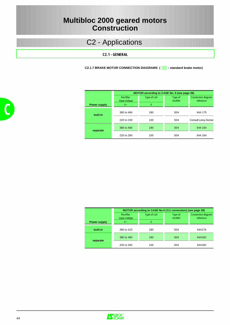
44
C
C2.1 - GENERAL
C2.1.7 BRAKE MOTOR CONNECTION DIAGRAMS ( : standard brake motor)
Multibloc 2000 geared motorsConstruction
C2 - Applications
MOTOR according to CASE No. 5 (see page 39)
Rectifier input voltage
Type of coil Type ofrectifier
Connection diagramreference
Power supply V~ V
380 to 460 180 S04 644 175
220 to 230 100 S04 Consult Leroy-Somer
380 to 460 180 S04 644 164
220 to 265 100 S04 644 164
built-in
separate
MOTOR according to CASE No.6 (Y/∆ connection) (see page 39)
Rectifier input voltage
Type of coil Type ofrectifier
Connection diagramreference
Power supply V~ V
built-in 380 to 415 180 S04 644176
380 to 460 180 S04 644160
220 to 265 100 S04 644160
separate
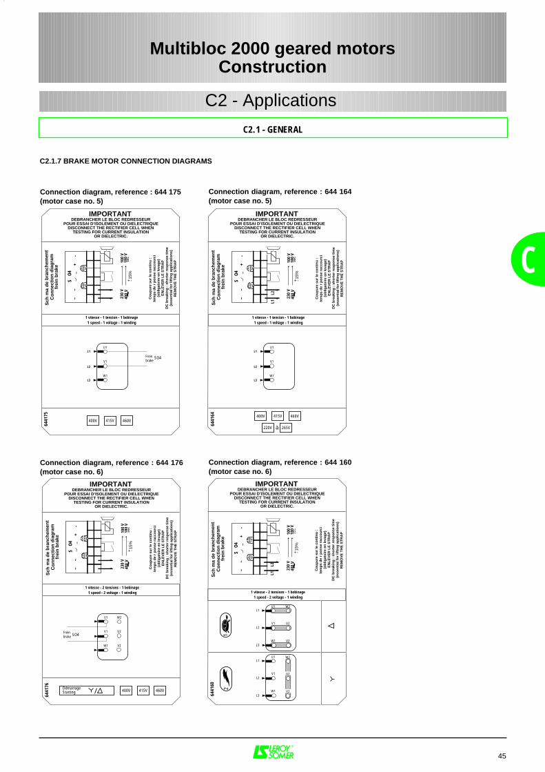
Sch
ma
de
bra
nch
emen
tC
on
nec
tio
n d
iag
ram
frei
n b
rake
S O
4~
~_
+-
DEBRANCHER LE BLOC REDRESSEURPOUR ESSAI D’ISOLEMENT OU DIELECTRIQUE
DISCONNECT THE RECTIFIER CELL WHENTESTING FOR CURRENT INSULATION
OR DIELECTRIC.
6441
60
IMPORTANT
1 vitesse - 2 tensions - 1 bobinage1 speed - 2 voltage - 1 winding
230
V40
0 V ~
100
V18
0 V
Co
up
ure
su
r le
co
nti
nu
:
tem
ps
de
rp
on
se r
acco
urc
i(o
blig
ato
ire
en le
vag
e)E
NL
EV
ER
LE
ST
RA
PD
C b
reak
ing
: s
ho
rter
res
po
nse
tim
e(e
ssen
tial
fo
r lif
tin
g a
pp
licat
ion
s)R
EM
OV
E T
HE
ST
RA
P
+ -15%
U1
V1
W1
12
U1
V1
W1
W2L1
L2
L3
L1
L2
L3
U2
V2
W2
V2
U2
L1L2
Sch
ma
de
bra
nch
emen
tC
on
nec
tio
n d
iag
ram
frei
n b
rake
S O
4~
~_
+-
DEBRANCHER LE BLOC REDRESSEURPOUR ESSAI D’ISOLEMENT OU DIELECTRIQUE
DISCONNECT THE RECTIFIER CELL WHENTESTING FOR CURRENT INSULATION
OR DIELECTRIC.
6441
64IMPORTANT
1 vitesse - 1 tension - 1 bobinage1 speed - 1 voltage - 1 winding
230
V40
0 V ~
100
V18
0 V
Co
up
ure
su
r le
co
nti
nu
:
tem
ps
de
rp
on
se r
acco
urc
i(o
blig
ato
ire
en le
vag
e)E
NL
EV
ER
LE
ST
RA
PD
C b
reak
ing
: s
ho
rter
res
po
nse
tim
e(e
ssen
tial
fo
r lif
tin
g a
pp
licat
ion
s)R
EM
OV
E T
HE
ST
RA
P
+ -15%
U1
V1
W1
400V
220V 265V
415V 460V
L1
L2
L3
L1L2
à
Sch
ma
de
bra
nch
emen
tC
on
nec
tio
n d
iag
ram
frei
n b
rake
S O
4~
~_
+-
DEBRANCHER LE BLOC REDRESSEURPOUR ESSAI D’ISOLEMENT OU DIELECTRIQUE
DISCONNECT THE RECTIFIER CELL WHENTESTING FOR CURRENT INSULATION
OR DIELECTRIC.
6441
75
IMPORTANT
1 vitesse - 1 tension - 1 bobinage1 speed - 1 voltage - 1 winding
230
V40
0 V ~
100
V18
0 V
Co
up
ure
su
r le
co
nti
nu
:
tem
ps
de
rp
on
se r
acco
urc
i(o
blig
ato
ire
en le
vag
e)E
NL
EV
ER
LE
ST
RA
PD
C b
reak
ing
: s
ho
rter
res
po
nse
tim
e(e
ssen
tial
fo
r lif
tin
g a
pp
licat
ion
s)R
EM
OV
E T
HE
ST
RA
P
+ -15%
U1
V1
W1
400V 415V 460V
Frein brake
L1
L2
L3
SO4
45
C
C2.1 - GENERAL
C2.1.7 BRAKE MOTOR CONNECTION DIAGRAMS
Connection diagram, reference : 644 175(motor case no. 5)
Multibloc 2000 geared motorsConstruction
C2 - Applications
Sch
ma
de
bra
nch
emen
tC
on
nec
tio
n d
iag
ram
frei
n b
rake
S O
4~
~_
+-
DEBRANCHER LE BLOC REDRESSEURPOUR ESSAI D’ISOLEMENT OU DIELECTRIQUE
DISCONNECT THE RECTIFIER CELL WHENTESTING FOR CURRENT INSULATION
OR DIELECTRIC.
6441
76
IMPORTANT
1 vitesse - 2 tensions - 1 bobinage1 speed - 2 voltage - 1 winding
230
V40
0 V ~
100
V18
0 V
Co
up
ure
su
r le
co
nti
nu
:
tem
ps
de
rp
on
se r
acco
urc
i(o
blig
ato
ire
en le
vag
e)E
NL
EV
ER
LE
ST
RA
PD
C b
reak
ing
: s
ho
rter
res
po
nse
tim
e(e
ssen
tial
fo
r lif
tin
g a
pp
licat
ion
s)R
EM
OV
E T
HE
ST
RA
P
+ -15%
U1
V1
W1
W2
U2
V2
400V 415V 460V
Frein brake
DémarrageStarting
SO4
Connection diagram, reference : 644 176(motor case no. 6)
Connection diagram, reference : 644 164(motor case no. 5)
Connection diagram, reference : 644 160(motor case no. 6)
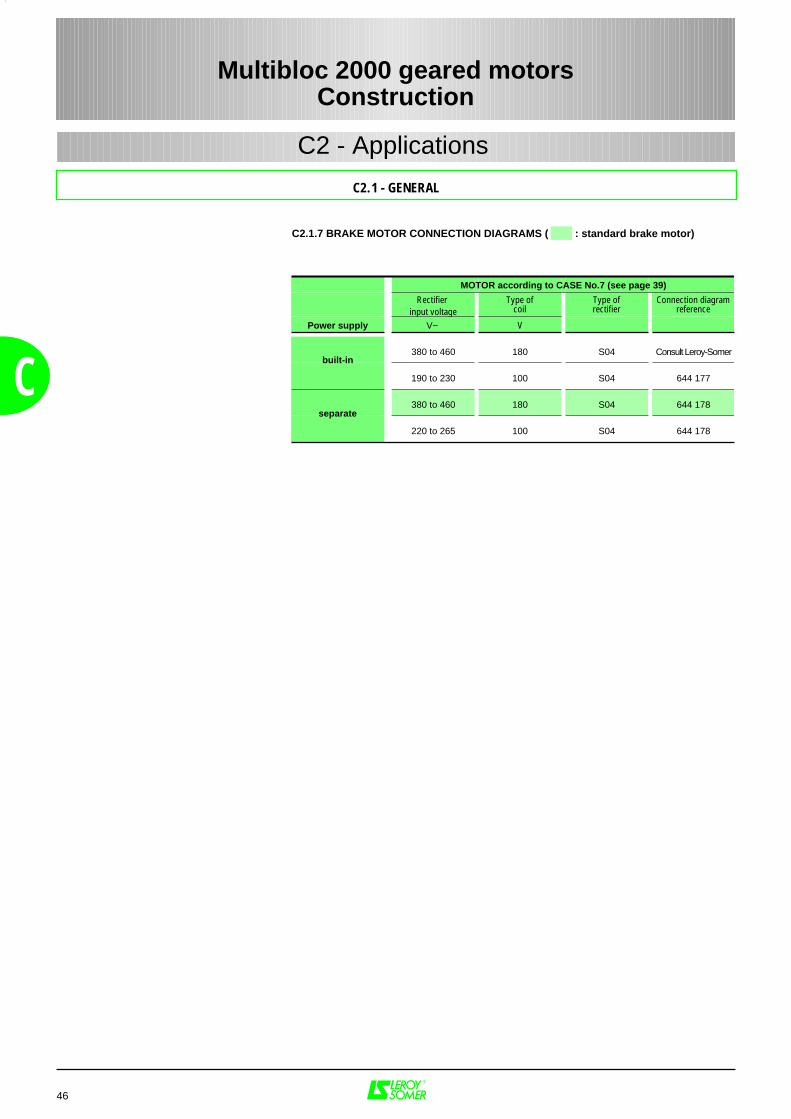
46
C
C2.1 - GENERAL
C2.1.7 BRAKE MOTOR CONNECTION DIAGRAMS ( : standard brake motor)
Multibloc 2000 geared motorsConstruction
C2 - Applications
MOTOR according to CASE No.7 (see page 39)
Rectifier input voltage
Type ofcoil
Type ofrectifier
Connection diagramreference
Power supply V~ V
380 to 460 180 S04 Consult Leroy-Somer
190 to 230 100 S04 644 177
380 to 460 180 S04 644 178
220 to 265 100 S04 644 178
built-in
separate
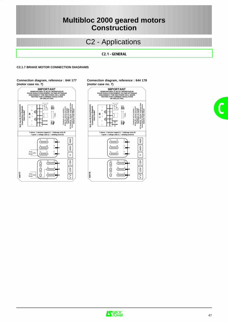
Sch
ma
de
bra
nch
emen
tC
on
nec
tio
n d
iag
ram
frei
n b
rake
S O
4~
~_
+-
DEBRANCHER LE BLOC REDRESSEURPOUR ESSAI D’ISOLEMENT OU DIELECTRIQUE
DISCONNECT THE RECTIFIER CELL WHENTESTING FOR CURRENT INSULATION
OR DIELECTRIC.
6441
77
IMPORTANT
1 vitesse - 2 tensions (rapport 2) - 1 bobinage (série II)1 speed - 2 voltage (ratio 2) - 1 winding (serial II)
230
V40
0 V ~
100
V18
0 V
Co
up
ure
su
r le
co
nti
nu
:
tem
ps
de
rp
on
se r
acco
urc
i(o
blig
ato
ire
en le
vag
e)E
NL
EV
ER
LE
ST
RA
PD
C b
reak
ing
: s
ho
rter
res
po
nse
tim
e(e
ssen
tial
fo
r lif
tin
g a
pp
licat
ion
s)R
EM
OV
E T
HE
ST
RA
P
+ -15%
220V
230V
440V
460V
T2
T3T9T6
T8T5
T7 T1T4FreinBrake
FreinBrake
T5
T6
T4
T8
T9
T7
T2
T3
T1
SO4
SO4
Sch
ma
de
bra
nch
emen
tC
on
nec
tio
n d
iag
ram
frei
n b
rake
S O
4~
~_
+-
DEBRANCHER LE BLOC REDRESSEURPOUR ESSAI D’ISOLEMENT OU DIELECTRIQUE
DISCONNECT THE RECTIFIER CELL WHENTESTING FOR CURRENT INSULATION
OR DIELECTRIC.
6441
78IMPORTANT
1 vitesse - 2 tensions (rapport 2) - 1 bobinage (série II)1 speed - 2 voltage (ratio 2) - 1 winding (serial II)
230
V40
0 V ~
100
V18
0 V
Co
up
ure
su
r le
co
nti
nu
:
tem
ps
de
rp
on
se r
acco
urc
i(o
blig
ato
ire
en le
vag
e)E
NL
EV
ER
LE
ST
RA
PD
C b
reak
ing
: s
ho
rter
res
po
nse
tim
e(e
ssen
tial
fo
r lif
tin
g a
pp
licat
ion
s)R
EM
OV
E T
HE
ST
RA
P
+ -15%
220V
230V
440V
460V
T2
T3T9T6
T8T5
T7 T1T4
T5
T6
T4
T8
T9
T7
T2
T3
T1
L1L2
47
C
C2.1 - GENERAL
C2.1.7 BRAKE MOTOR CONNECTION DIAGRAMS
Connection diagram, reference : 644 177(motor case no. 7)
Multibloc 2000 geared motorsConstruction
C2 - Applications
Connection diagram, reference : 644 178(motor case no. 7)
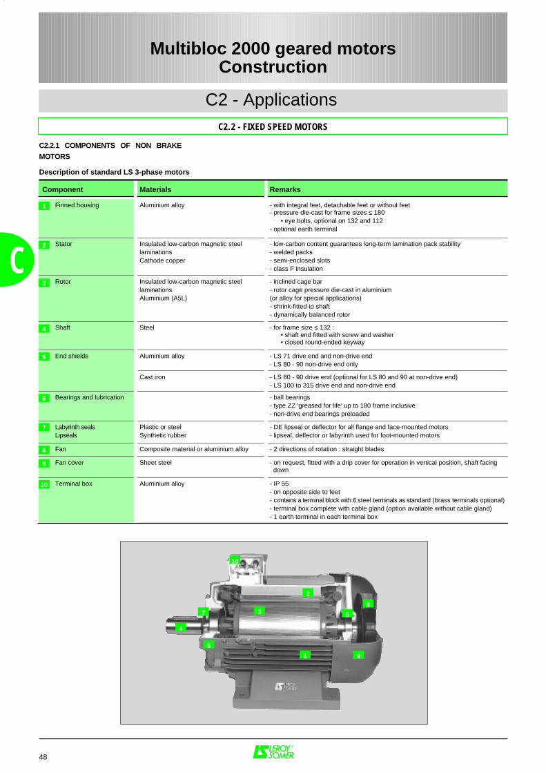
48
C2 - Applications
C2.2.1 COMPONENTS OF NON BRAKE
MOTORS
C
C2.2 - FIXED SPEED MOTORS
Component Materials Remarks
Finned housing Aluminium alloy - with integral feet, detachable feet or without feet- pressure die-cast for frame sizes ≤ 180
• eye bolts, optional on 132 and 112- optional earth terminal
Stator Insulated low-carbon magnetic steellaminationsCathode copper
- low-carbon content guarantees long-term lamination pack stability- welded packs- semi-enclosed slots- class F insulation
Rotor Insulated low-carbon magnetic steellaminationsAluminium (A5L)
- inclined cage bar- rotor cage pressure die-cast in aluminium(or alloy for special applications)- shrink-fitted to shaft- dynamically balanced rotor
Shaft Steel - for frame size ≤ 132 :• shaft end fitted with screw and washer • closed round-ended keyway
End shields Aluminium alloy
Cast iron
- LS 71 drive end and non-drive end- LS 80 - 90 non-drive end only
- LS 80 - 90 drive end (optional for LS 80 and 90 at non-drive end)- LS 100 to 315 drive end and non-drive end
Bearings and lubrication - ball bearings- type ZZ 'greased for life' up to 180 frame inclusive- non-drive end bearings preloaded
Labyrinth sealsLipseals
Plastic or steelSynthetic rubber
- DE lipseal or deflector for all flange and face-mounted motors- lipseal, deflector or labyrinth used for foot-mounted motors
Fan Composite material or aluminium alloy - 2 directions of rotation : straight blades
Fan cover Sheet steel - on request, fitted with a drip cover for operation in vertical position, shaft facing down
Terminal box Aluminium alloy - IP 55- on opposite side to feet- contains a terminal block with 6 steel terminals as standard (brass terminals optional)- terminal box complete with cable gland (option available without cable gland)- 1 earth terminal in each terminal box
1
2
3
4
5
6
7
10
8
9
67
2
4
3
9
10
5
8
Description of standard LS 3-phase motors
1
Multibloc 2000 geared motorsConstruction
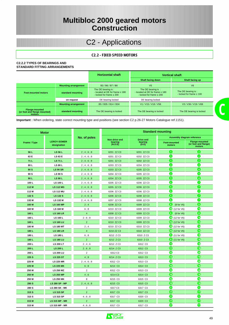
No. of poles
Frame / Type LEROY-SOMER Foot-mounteddesignation motors
56 L LS 56 L 2 ; 4 ; 6 ; 8 6201 ZZ C3 6201 ZZ C3
63 E LS 63 E 2 ; 4 ; 6 ; 8 6201 ZZ C3 6202 ZZ C3
71 L LS 71 L 2 ; 4 ; 6 ; 8 6201 ZZ C3 6202 ZZ C3
80 L LS 80 L 2 ; 4 ; 6 ; 8 6203 ZZ C3 6204 ZZ C3
90 S LS 90 SR 2 ; 4 ; 6 ; 8 6203 ZZ C3 6205 ZZ C3
90 S LS 90 S 2 ; 4 ; 6 ; 8 6204 ZZ C3 6205 ZZ C3
90 L LS 90 L 2 ; 4 ; 6 ; 8 6204 ZZ C3 6205 ZZ C3
100 L LS 100 L 2 ; 4 ; 6 ; 8 6205 ZZ C3 6206 ZZ C3
112 M LS 112 MG 2 ; 4 ; 6 ; 8 6205 ZZ C3 6206 ZZ C3
112 M LS 112 MU 2 ; 4 ; 6 ; 8 6206 ZZ C3 6206 ZZ C3
132 S LS 132 S 2 ; 4 ; 6 ; 8 6206 ZZ C3 6208 ZZ C3
132 M LS 132 M 2 ; 4 ; 6 ; 8 6207 ZZ C3 6308 ZZ C3
160 M LS 160 MP 2 ; 4 6208 ZZ C3 6309 ZZ C3 (8 for V6)
160 M LS 160 M 6 ; 8 6210 ZZ C3 6309 ZZ C3 (12 for V6)
160 L LS 160 LR 4 6308 ZZ C3 6309 ZZ C3 (8 for V6)
160 L LS 160 L 2 ; 6 ; 8 6210 ZZ C3 6309 ZZ C3 (12 for V6)
160 L LS 160 LU 2 6210 ZZ C3 6309 ZZ C3 (12 for V6)
180 M LS 180 MT 2 ; 4 6210 ZZ C3 6310 ZZ C3 (12 for V6)
180 L LS 180 LR 4 6210 ZZ C3 6310 ZZ C3 (12 for V6)
180 L LS 180 L 6 ; 8 6212 Z C3 6310 Z C3 (11 for V6)
180 L LS 180 LU 2 6212 Z C3 6310 Z C3 (11 for V6)
200 L LS 200 LT 2 ; 4 ; 6 6212 Z C3 6312 C3
200 L LS 200 L 2 ; 6 ; 8 6214 Z C3 6312 C3
200 L LS 200 LU 2 6312 C3 6312 C3
225 S LS 225 ST 4 ; 8 6214 Z C3 6313 C3
225 M LS 225 MR 2 ; 4 ; 6 ; 8 6312 C3 6313 C3
225 M LS 225 MK 6 ; 8 6214 C3 6314 C3
250 M LS 250 MZ 2 6312 C3 6313 C3
250 M LS 250 MP 4 ; 6 6214 C3 6314 C3
250 M LS 250 MK 8 6215 C3 6315 C3
280 S LS 280 SP - MP 2 ; 4 ; 6 ; 8 6215 C3 6315 C3
280 S LS 280 SK - MK 2 6317 C3 6317 C3
315 S LS 315 SP 2 6317 C3 6317 C3
315 S LS 315 SP 4 ; 6 ; 8 6317 C3 6320 C3
315 M LS 315 MP - MR 2 6317 C3 6320 C3
315 M LS 315 MP - MR 4 ; 6 ; 8 6317 C3 6317 C3
1 2
1 2
1
3 4
3 4
3 4
3 4
5 7
5 7
5 7
5 7
5 7
6 8
10 14
6 8
10 14
10 14
10 14
10 14
9 18
9 18
11 18
11 18
15 20
13 19
15 20
16 16
15 20
16 16
16 16
16 16
2
17
17 17
17
17 17
17 17
17 17
49
C
C2.2.2 TYPES OF BEARINGS ANDSTANDARD FITTING ARRANGEMENTS
Multibloc 2000 geared motorsConstruction
C2 - Applications
C2.2 - FIXED SPEED MOTORS
Horizontal shaft
Shaft facing down Shaft facing up
Mounting arrangement B3 / B6 / B7 / B8 V5 V6
Foot-mounted motors standard mounting The DE bearing is : - located at DE for frame ≤ 180 - locked for frame ≥ 200
The DE bearing is :- located at DE for frame ≤ 180
- locked for frame ≥ 200
The DE bearing is :- locked for frame ≥ 100
on request DE bearing locked DE bearing locked
Mounting arrangement B5 / B35 / B14 / B34 V1 / V15 / V18 / V58 V3 / V36 / V19 / V69
Flange-mounted(or foot and flange mounted)
motors standard mounting The DE bearing is locked The DE bearing is locked The DE bearing is locked
Vertical shaft
Important : When ordering, state correct mounting type and positions (see section C2 p.26-27 Motors Catalogue ref.1151).
Motor Standard mounting
Assembly diagram referenceNon drive end
bearing(N.D.E)
Drive endbearing
(D.E)Flange-mounted
(or foot and flange)motors
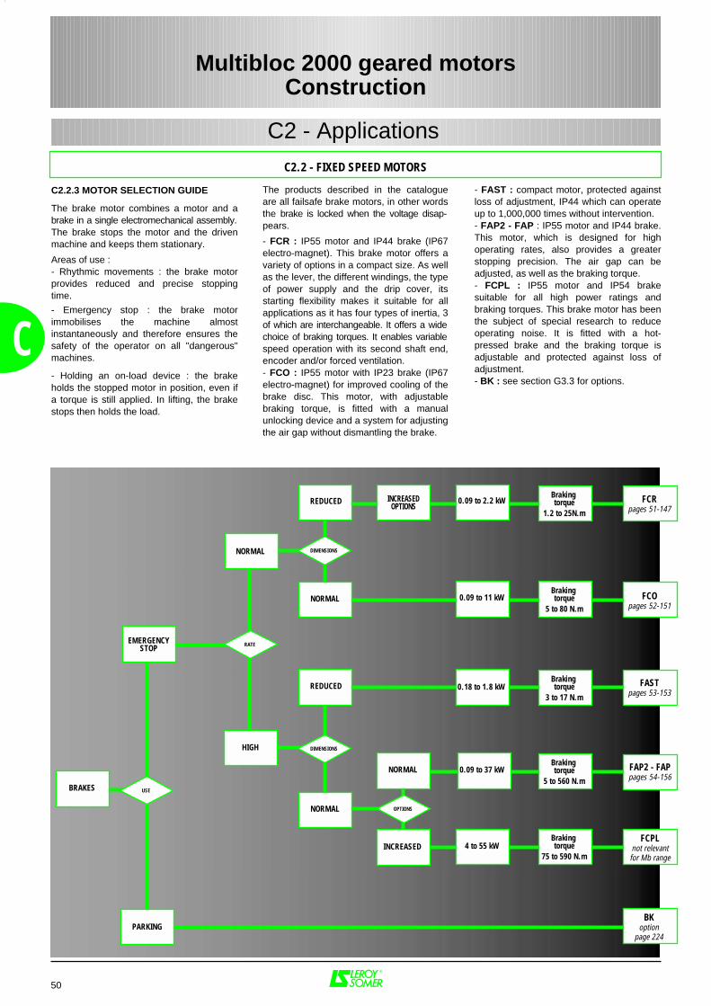
HIGH
0.09 to 11 kWBraking torque
5 to 80 N.m
Braking torque
1.2 to 25N.m
Braking torque
3 to 17 N.m
Braking torque
5 to 560 N.m
Braking torque
75 to 590 N.mINCREASED
FCPLnot relevantfor Mb range
BKoption
page 224
FASTpages 53-153
FCOpages 52-151
0.09 to 2.2 kW FCRpages 51-147
INCREASEDOPTIONS
4 to 55 kW
0.18 to 1.8 kW
BRAKES
REDUCED
DIMENSIONS
NORMAL
NORMAL
REDUCED
DIMENSIONS
NORMAL
OPTIONS
RATE
USE
NORMAL FAP2 - FAPpages 54-156
0.09 to 37 kW
EMERGENCYSTOP
PARKING
50
C
C2.2.3 MOTOR SELECTION GUIDE
The brake motor combines a motor and abrake in a single electromechanical assembly.The brake stops the motor and the drivenmachine and keeps them stationary.
Areas of use :- Rhythmic movements : the brake motorprovides reduced and precise stoppingtime.
- Emergency stop : the brake motorimmobilises the machine almostinstantaneously and therefore ensures thesafety of the operator on all "dangerous"machines.
- Holding an on-load device : the brakeholds the stopped motor in position, even ifa torque is still applied. In lifting, the brakestops then holds the load.
The products described in the catalogueare all failsafe brake motors, in other wordsthe brake is locked when the voltage disap-pears.
- FCR : IP55 motor and IP44 brake (IP67electro-magnet). This brake motor offers avariety of options in a compact size. As wellas the lever, the different windings, the typeof power supply and the drip cover, itsstarting flexibility makes it suitable for allapplications as it has four types of inertia, 3of which are interchangeable. It offers a widechoice of braking torques. It enables variablespeed operation with its second shaft end,encoder and/or forced ventilation.- FCO : IP55 motor with IP23 brake (IP67electro-magnet) for improved cooling of thebrake disc. This motor, with adjustablebraking torque, is fitted with a manualunlocking device and a system for adjustingthe air gap without dismantling the brake.
- FAST : compact motor, protected againstloss of adjustment, IP44 which can operateup to 1,000,000 times without intervention.- FAP2 - FAP : IP55 motor and IP44 brake.This motor, which is designed for highoperating rates, also provides a greaterstopping precision. The air gap can beadjusted, as well as the braking torque.- FCPL : IP55 motor and IP54 brakesuitable for all high power ratings andbraking torques. This brake motor has beenthe subject of special research to reduceoperating noise. It is fitted with a hot-pressed brake and the braking torque isadjustable and protected against loss ofadjustment.- BK : see section G3.3 for options.
Multibloc 2000 geared motorsConstruction
C2 - Applications
C2.2 - FIXED SPEED MOTORS
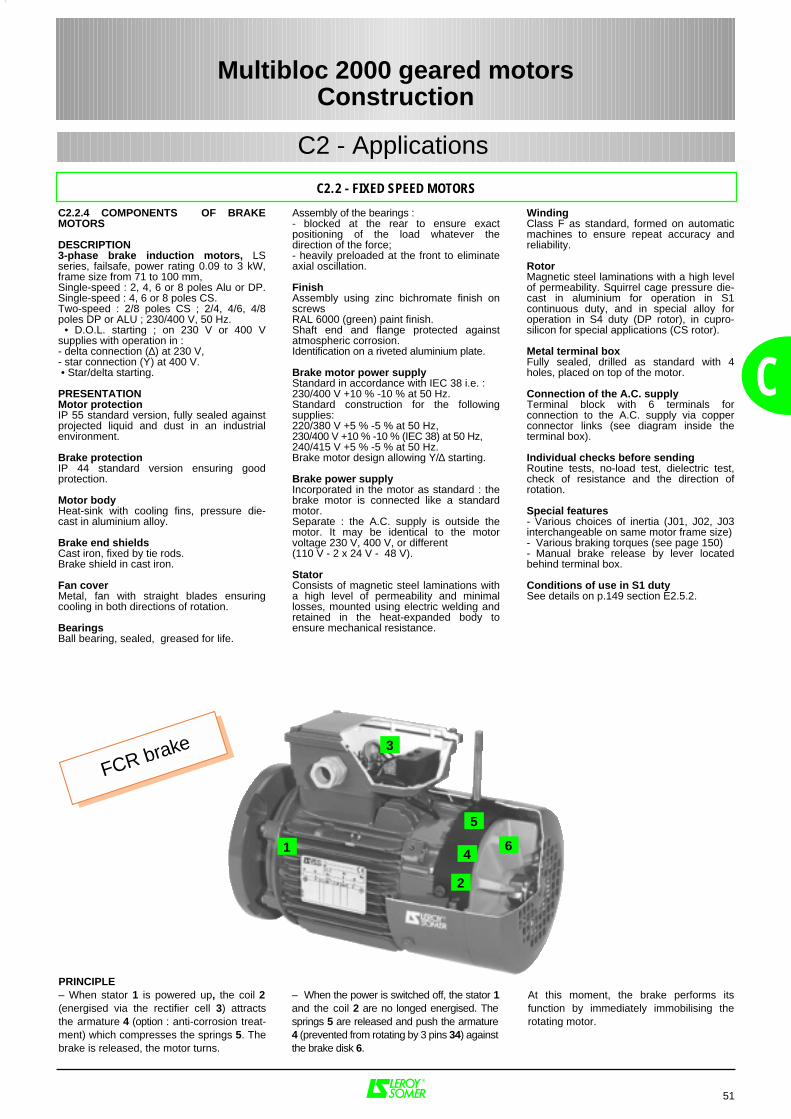
51
C2 - Applications
C
C2.2 - FIXED SPEED MOTORS
C2.2.4 COMPONENTS OF BRAKEMOTORS
DESCRIPTION3-phase brake induction motors, LSseries, failsafe, power rating 0.09 to 3 kW,frame size from 71 to 100 mm,Single-speed : 2, 4, 6 or 8 poles Alu or DP.Single-speed : 4, 6 or 8 poles CS.Two-speed : 2/8 poles CS ; 2/4, 4/6, 4/8poles DP or ALU ; 230/400 V, 50 Hz. • D.O.L. starting ; on 230 V or 400 Vsupplies with operation in :- delta connection (∆) at 230 V,- star connection (Υ) at 400 V. • Star/delta starting.
PRESENTATIONMotor protection IP 55 standard version, fully sealed againstprojected liquid and dust in an industrialenvironment.
Brake protectionIP 44 standard version ensuring goodprotection.
Motor bodyHeat-sink with cooling fins, pressure die-cast in aluminium alloy.
Brake end shields Cast iron, fixed by tie rods.Brake shield in cast iron.
Fan coverMetal, fan with straight blades ensuringcooling in both directions of rotation.
BearingsBall bearing, sealed, greased for life.
PRINCIPLE– When stator 1 is powered up, the coil 2(energised via the rectifier cell 3) attractsthe armature 4 (option : anti-corrosion treat-ment) which compresses the springs 5. Thebrake is released, the motor turns.
– When the power is switched off, the stator 1and the coil 2 are no longed energised. Thesprings 5 are released and push the armature4 (prevented from rotating by 3 pins 34) againstthe brake disk 6.
At this moment, the brake performs itsfunction by immediately immobilising therotating motor.
1
2
3
Multibloc 2000 geared motorsConstruction
4
5
6
Winding Class F as standard, formed on automaticmachines to ensure repeat accuracy andreliability.
Rotor Magnetic steel laminations with a high levelof permeability. Squirrel cage pressure die-cast in aluminium for operation in S1continuous duty, and in special alloy foroperation in S4 duty (DP rotor), in cupro-silicon for special applications (CS rotor). Metal terminal boxFully sealed, drilled as standard with 4holes, placed on top of the motor.
Connection of the A.C. supply Terminal block with 6 terminals forconnection to the A.C. supply via copperconnector links (see diagram inside theterminal box).
Individual checks before sending Routine tests, no-load test, dielectric test,check of resistance and the direction ofrotation.
Special features- Various choices of inertia (J01, J02, J03interchangeable on same motor frame size)- Various braking torques (see page 150)- Manual brake release by lever locatedbehind terminal box.
Conditions of use in S1 dutySee details on p.149 section E2.5.2.
Assembly of the bearings : - blocked at the rear to ensure exactpositioning of the load whatever thedirection of the force;- heavily preloaded at the front to eliminateaxial oscillation.
FinishAssembly using zinc bichromate finish onscrews RAL 6000 (green) paint finish. Shaft end and flange protected againstatmospheric corrosion. Identification on a riveted aluminium plate.
Brake motor power supplyStandard in accordance with IEC 38 i.e. :230/400 V +10 % -10 % at 50 Hz.Standard construction for the followingsupplies:220/380 V +5 % -5 % at 50 Hz,230/400 V +10 % -10 % (IEC 38) at 50 Hz,240/415 V +5 % -5 % at 50 Hz.Brake motor design allowing Υ/∆ starting.
Brake power supplyIncorporated in the motor as standard : thebrake motor is connected like a standardmotor.Separate : the A.C. supply is outside themotor. It may be identical to the motorvoltage 230 V, 400 V, or different (110 V - 2 x 24 V - 48 V).
Stator Consists of magnetic steel laminations witha high level of permeability and minimallosses, mounted using electric welding andretained in the heat-expanded body toensure mechanical resistance.
FCR brake
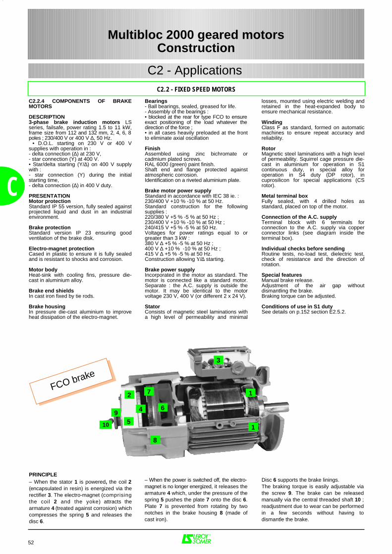
losses, mounted using electric welding andretained in the heat-expanded body toensure mechanical resistance.
Winding Class F as standard, formed on automaticmachines to ensure repeat accuracy andreliability.
Rotor Magnetic steel laminations with a high levelof permeability. Squirrel cage pressure die-cast in aluminium for operation in S1continuous duty, in special alloy foroperation in S4 duty (DP rotor), incuprosilicon for special applications (CSrotor). Metal terminal boxFully sealed, with 4 drilled holes asstandard, placed on top of the motor.
Connection of the A.C. supply Terminal block with 6 terminals forconnection to the A.C. supply via copperconnector links (see diagram inside theterminal box).
Individual checks before sending Routine tests, no-load test, dielectric test,check of resistance and the direction ofrotation.
Special featuresManual brake release.Adjustment of the air gap withoutdismantling the brake.Braking torque can be adjusted.
Conditions of use in S1 dutySee details on p.152 section E2.5.2.
52
C2 - Applications
C
C2.2 - FIXED SPEED MOTORS
PRINCIPLE– When the stator 1 is powered, the coil 2(encapsulated in resin) is energized via therectifier 3. The electro-magnet (comprisingthe coil 2 and the yoke) attracts thearmature 4 (treated against corrosion) whichcompresses the spring 5 and releases thedisc 6.
– When the power is switched off, the electro-magnet is no longer energized, it releases thearmature 4 which, under the pressure of thespring 5 pushes the plate 7 onto the disc 6.Plate 7 is prevented from rotating by twonotches in the brake housing 8 (made ofcast iron).
Disc 6 supports the brake linings.The braking torque is easily adjustable viathe screw 9. The brake can be releasedmanually via the central threaded shaft 10 ;readjustment due to wear can be performedin a few seconds without having todismantle the brake.
1
12
3
4
5
6
7
8
9
10
Multibloc 2000 geared motorsConstruction
C2.2.4 COMPONENTS OF BRAKEMOTORS
DESCRIPTION3-phase brake induction motors LSseries, failsafe, power rating 1.5 to 11 kW,frame size from 112 and 132 mm, 2, 4, 6, 8poles ; 230/400 V or 400 V ∆, 50 Hz. • D.O.L. starting on 230 V or 400 Vsupplies with operation in :- delta connection (∆) at 230 V,- star connection (Υ) at 400 V.• Star/delta starting (Υ/∆) on 400 V supplywith :- star connection (Υ) during the initialstarting time,- delta connection (∆) in 400 V duty.
PRESENTATIONMotor protectionStandard IP 55 version, fully sealed againstprojected liquid and dust in an industrialenvironment.
Brake protectionStandard version IP 23 ensuring goodventilation of the brake disk.
Electro-magnet protectionCased in plastic to ensure it is fully sealedand is resistant to shocks and corrosion.
Motor bodyHeat-sink with cooling fins, pressure die-cast in aluminium alloy.
Brake end shields In cast iron fixed by tie rods.
Brake housingIn pressure die-cast aluminium to improveheat dissipation of the electro-magnet.
Bearings- Ball bearings, sealed, greased for life.- Assembly of the bearings :• blocked at the rear for type FCO to ensureexact positioning of the load whatever thedirection of the force ;• in all cases heavily preloaded at the frontto eliminate axial oscillation
FinishAssembled using zinc bichromate orcadmium plated screws.RAL 6000 (green) paint finish. Shaft end and flange protected againstatmospheric corrosion. Identification on a riveted aluminium plate.
Brake motor power supplyStandard in accordance with IEC 38 ie. :230/400 V +10 % -10 % at 50 Hz.Standard construction for the followingsupplies :220/380 V +5 % -5 % at 50 Hz ;230/400 V +10 % -10 % at 50 Hz ;240/415 V +5 % -5 % at 50 Hz.Voltages for power ratings equal to orgreater than 3 kW :380 V ∆ +5 % -5 % at 50 Hz ;400 V ∆ +10 % -10 % at 50 Hz ;415 V ∆ +5 % -5 % at 50 Hz.Construction allowing Y/∆ starting.
Brake power supplyIncorporated in the motor as standard. Themotor is connected like a standard motor.Separate : the A.C. supply is outside themotor. It may be identical to the motorvoltage 230 V, 400 V (or different 2 x 24 V). Stator Consists of magnetic steel laminations witha high level of permeability and minimal
FCO brake
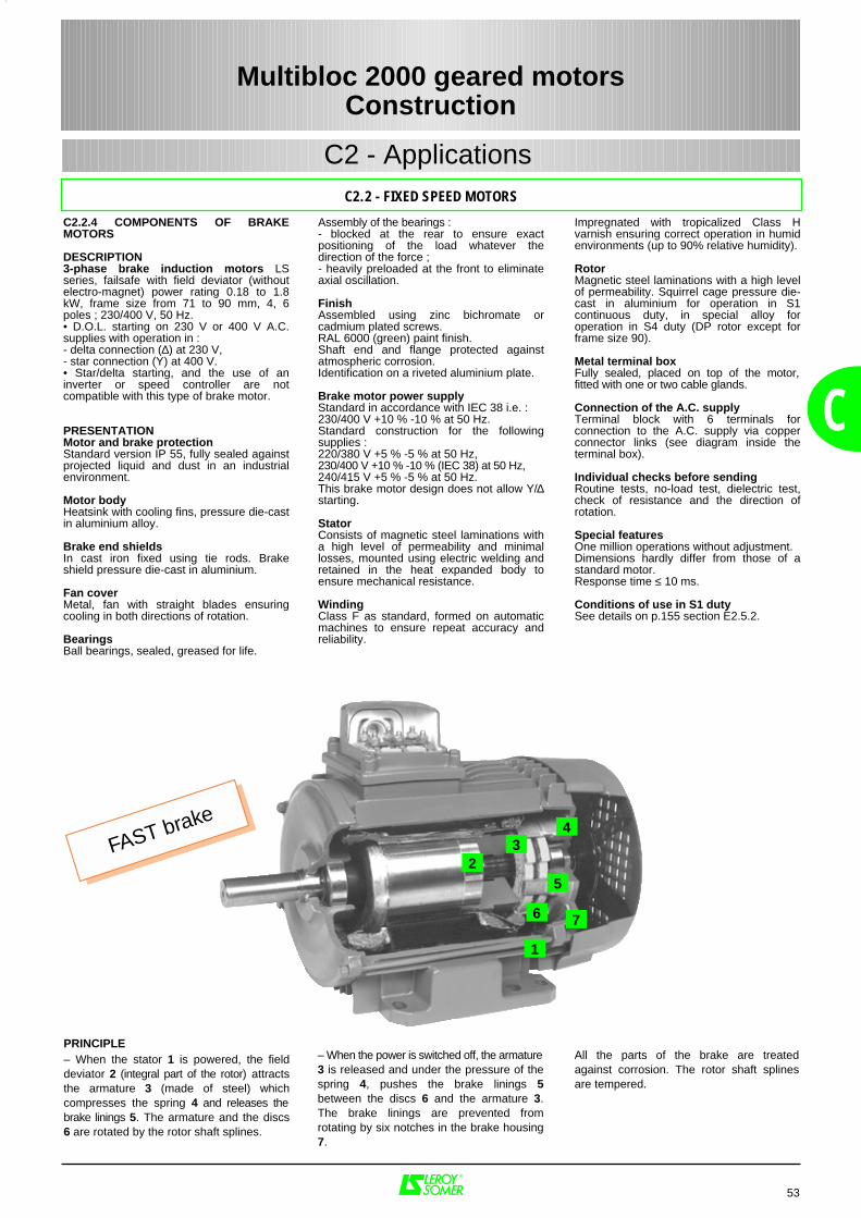
Assembly of the bearings : - blocked at the rear to ensure exactpositioning of the load whatever thedirection of the force ;- heavily preloaded at the front to eliminateaxial oscillation.
FinishAssembled using zinc bichromate orcadmium plated screws. RAL 6000 (green) paint finish. Shaft end and flange protected againstatmospheric corrosion. Identification on a riveted aluminium plate.
Brake motor power supplyStandard in accordance with IEC 38 i.e. :230/400 V +10 % -10 % at 50 Hz.Standard construction for the followingsupplies :220/380 V +5 % -5 % at 50 Hz,230/400 V +10 % -10 % (IEC 38) at 50 Hz,240/415 V +5 % -5 % at 50 Hz.This brake motor design does not allow Υ/∆starting.
Stator Consists of magnetic steel laminations witha high level of permeability and minimallosses, mounted using electric welding andretained in the heat expanded body toensure mechanical resistance.
Winding Class F as standard, formed on automaticmachines to ensure repeat accuracy andreliability.
Impregnated with tropicalized Class Hvarnish ensuring correct operation in humidenvironments (up to 90% relative humidity).
Rotor Magnetic steel laminations with a high levelof permeability. Squirrel cage pressure die-cast in aluminium for operation in S1continuous duty, in special alloy foroperation in S4 duty (DP rotor except forframe size 90). Metal terminal boxFully sealed, placed on top of the motor,fitted with one or two cable glands.
Connection of the A.C. supply Terminal block with 6 terminals forconnection to the A.C. supply via copperconnector links (see diagram inside theterminal box).
Individual checks before sending Routine tests, no-load test, dielectric test,check of resistance and the direction ofrotation.
Special featuresOne million operations without adjustment.Dimensions hardly differ from those of astandard motor.Response time ≤ 10 ms.
Conditions of use in S1 dutySee details on p.155 section E2.5.2.
53
C2 - Applications
C
C2.2 - FIXED SPEED MOTORS
C2.2.4 COMPONENTS OF BRAKEMOTORS
DESCRIPTION3-phase brake induction motors LSseries, failsafe with field deviator (withoutelectro-magnet) power rating 0.18 to 1.8kW, frame size from 71 to 90 mm, 4, 6poles ; 230/400 V, 50 Hz.• D.O.L. starting on 230 V or 400 V A.C.supplies with operation in :- delta connection (∆) at 230 V,- star connection (Υ) at 400 V.• Star/delta starting, and the use of aninverter or speed controller are notcompatible with this type of brake motor.
PRESENTATIONMotor and brake protectionStandard version IP 55, fully sealed againstprojected liquid and dust in an industrialenvironment.
Motor bodyHeatsink with cooling fins, pressure die-castin aluminium alloy.
Brake end shields In cast iron fixed using tie rods. Brakeshield pressure die-cast in aluminium.
Fan coverMetal, fan with straight blades ensuringcooling in both directions of rotation.
BearingsBall bearings, sealed, greased for life.
PRINCIPLE– When the stator 1 is powered, the fielddeviator 2 (integral part of the rotor) attractsthe armature 3 (made of steel) whichcompresses the spring 4 and releases thebrake linings 5. The armature and the discs6 are rotated by the rotor shaft splines.
– When the power is switched off, the armature3 is released and under the pressure of thespring 4, pushes the brake linings 5between the discs 6 and the armature 3.The brake linings are prevented fromrotating by six notches in the brake housing7.
All the parts of the brake are treatedagainst corrosion. The rotor shaft splinesare tempered.
1
23
4
6 7
5
Multibloc 2000 geared motorsConstruction
FAST brake
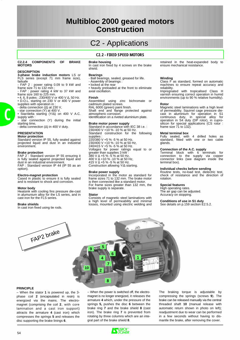
FAP2 brake
Brake housingIn cast iron fixed by 4 screws on the brakeshield.
Bearings- Ball bearings, sealed, greased for life. - Assembly of bearings :• locked at the rear• heavily preloaded at the front to eliminateaxial oscillation.
FinishAssembled using zinc bichromate orcadmium plated screws. RAL 6000 (green) paint finish. Shaft end and flange protected againstatmospheric corrosion. Identification on a riveted aluminium plate.
Brake motor power supplyStandard in accordance with IEC 38 i.e. :230/400 V +10 % -10 % at 50 Hz.Standard construction for the followingsupplies :220/380 V +5 % -5 % at 50 Hz,230/400 V +10 % -10 % at 50 Hz,240/415 V +5 % -5 % at 50 Hz.Voltages for power ratings equal to orgreater than supplies 3 kW :380 V ∆ +5 % -5 % at 50 Hz,400 V ∆ +10 % -10 % at 50 Hz,415 V ∆ +5 % -5 % at 50 Hz.Construction allowing Υ/∆ starting.
Brake power supplyIncorporated in the motor as standard forframe sizes 71 to 132 mm. The brake motoris then connected like a standard motor.For frame sizes greater than 132 mm, thebrake supply is separate.
Stator Consists of magnetic steel laminations witha high level of permeability and minimallosses, mounted using electric welding and
retained in the heat-expanded body toensure mechanical resistance.
Winding Class F as standard, formed on automaticmachines to ensure repeat accuracy andreliability. Impregnated with tropicalised Class Hvarnish ensuring correct operation in humidenvironments (up to 90 % relative humidity).
Rotor Magnetic steel laminations with a high levelof permeability. Squirrel cage pressure die-cast in aluminium for operation in S1continuous duty, in special alloy foroperation in S4 duty (DP rotor), in cupro-silicon for special applications (CS rotor :frame size 71 to 132).
Metal terminal boxFully sealed, with 4 drilled holes asstandard, fitted with one or two cableglands.
Connection of the A.C. supply Terminal block with 6 terminals forconnection to the supply via copperconnector links (see diagram inside theterminal box).
Individual checks before sending Routine tests, no-load test, dielectric test,check of resistance and the direction ofrotation.
Special featuresHigh operating rates.The air gap can be adjusted.Accuracy on stopping.
Conditions of use in S1 dutySee details on p.159 section E2.5.2.
54
C2 - Applications
C
C2.2 - FIXED SPEED MOTORS
C2.2.4 COMPONENTS OF BRAKEMOTORS
DESCRIPTION3-phase brake induction motors LS orFLS series (except 71 mm frame size),failsafe - FAP 2 : power rating 0.09 to 9 kW andframe size 71 to 132 mm ;- FAP : power rating 4 kW to 37 kW andframe size 160 to 225 mm.• 4, 6, 8 poles ; 230/400 V or 400 V ∆, 50 Hz.• D.O.L. starting on 230 V or 400 V powersupplies with operation in :- delta connection (∆) at 230 V,- star connection (Υ) at 400 V.• Star/delta starting (Υ/∆) on 400 V A.C.supply with :- star connection (Υ) during the initialstarting time,- delta connection (∆) in 400 V duty.
PRESENTATIONMotor protectionStandard version IP 55, fully sealed againstprojected liquid and dust in an industrialenvironment.
Brake protectionFAP 2 : Standard version IP 55 ensuring itis fully sealed against projected liquid anddust in an industrial environment.FAP : Standard version IP 44 (IP 55 as anoption).
Electro-magnet protectionCased in plastic to ensure it is fully sealedand is resistant to shock and corrosion. Motor bodyHeatsink with cooling fins pressure die-castin alumunium alloy for the LS series, and incast iron for the FLS series.
Brake shieldsIn cast iron fixed using tie rods.
Multibloc 2000 geared motorsConstruction
– When the power is switched off, the electro-magnet is no longer energized, it releases thearmature 4 which, under the pressure of thesprings 5, pushes the disc 6 between thebrake ring 7 and the brake shield 8 (castiron). The brake ring 7 is prevented fromrotating by three columns which are an inte-gral part of the brake shield 8.
The braking torque is adjustable bycompressing the springs (screws 9). Thebrake can be released manually via the centralthreaded shaft 10 (manual release withautomatic return shown in photo on left);readjustment due to wear can be performedin a few seconds without having to dis-mantle the brake, after removing the cover.
1
2
47
8
10
PRINCIPLE– When the stator 1 is powered up, the 3-phase coil 2 (encapsulated in resin) isenergized via the mains. The electro-magnet (comprising the coil 2, with corelamination and a cast iron support)attracts the armature 4 (cast iron) whichcompresses the springs 5 and releases thedisc supporting the brake linings 6.
6
59

55
C
C2.2.5 TYPES OF BEARINGS FORBRAKE MOTORSThe definition and characteristics of thebearings are detailed on page 49 and insection C3 of the Motors catalogueref.1151. For standard cases, the typesused are listed in the table below :
C2.2 - FIXED SPEED MOTORS
STANDARD MOUNTINGDrive end bearing
(D.E.)1Non Drive End Bearing
(N.D.E.)2
Motortype
Braketype B3 / B14 MU B5 MU B5 MI VA
FAST 6202-2RS 6004-2RS 6004-2RS 6202-2RSLS 71 FCR 6004-2RS 6004-2RS 6004-2RS 6202-2RS
FAP2 6202-2RS 6004-2RS 6004-2RS 6003-2RSFCR / FAP2 6204-2RS 6204-2RS 6204-2RS 6204-2RS
FAST 6204-2RS 6204-2RS 6204-2RS 6203-2RSFCR / FAP2 6205-2RS 6205-2RS 6205-2RS 6205-2RS
FAST 6205-2RS 6205-2RS 6205-2RS 6204-2RSLS 100 FCR / FAP2 6206-2RS 6206-2RS 6206-2RS 6205-2RS / 6206-2RSLS 112 FCO / FAP2 6206-2RS 6206-2RS 6206-2RS 6206-2RSLS 132 FCO / FAP2 6308-2RS 6308-2RS 6308-2RS 6308-2RSLS 160 L FAP / FCPL 6309-2RS/C3 6309-2RS/C3 6310-2RS/C3 6210-2RS / C3LS 180 MT FAP / FCPL 6310-2RS/C3 6310-2RS/C3 6310-2RS/C3 6210-2RS / C3LS 180 L FAP / FCPL 6310-2RS/C3 6310-2RS/C3 6310-2RS/C3 6212-2RS / C3LS 200 LT FAP / FCPL 6312-2RS/C3 6312-2RS/C3 6312-2RS/C3 6212-2RS / C3LS 200 L FAP / FCPL 6312-2RS/C3 6312-2RS/C3 6313-2RS/C3* 6312-2RS / C3LS 225 ST FAP / FCPL 6313-2RS/C3 6313-2RS/C3 6313-2RS/C3 6312-2RS / C3LS 225 M FAP / FCPL 6314 / C3 6314 / C3 6314 / C3 6214 / C3LS 250 MP FAP / FCPL 6314 / C3 6314 / C3 6314 / C3 6214 / C3LS 250 MK FAP / FCPL 6315 / C3 6315 /C3 6315 / C3 6215 / C3
Drive end bearing (D.E.)1 : drive end bearing (Drive End)Non drive end bearing (N.D.E.)2 : non drive end bearing (Non Drive End)
* 6313-2RS/C3 becomes 6312-2RS/C3 with flange FF265
LS 80
LS 90
Multibloc 2000 geared motorsConstruction
C2 - Applications
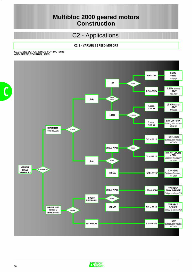
56
C2 - Applications
C
Multibloc 2000 geared motors
Construction
LS MV Open loop
+ UMVnext page
LS MV Closed loop
+ UMVnext page
SMV UM + UMV Catalogue for Industry
ref. 2434
MVPCatalogue for Industry
ref. 2434
VARMECASINGLE-PHASE
Catalogue for Industry ref2434
LSK + DMVCatalogue for Industry
ref. 2434
MFA-MF, LSK, MS+ DMV
Catalogue for Industry ref. 2434
MVE - MVSCatalogue for Industry
ref. 2434
VARMECA3-PHASE
Catalogue for Industry ref2434
LS MV+ FMV
next page
VARIABLE SPEEDMOTORS or
GEARED MOTORS
MOTOR SPEED CONTROLLERS
SUPPLY
SYSTEM
MECHANICAL
D.C.
BUILT-INELECTRONICS
A.C.
POWER
POWER
DYNAMIC
0.07 to 2.2 kW
0.5 to 18.5 kW
0.75 to 4 kW
T. accel.> 100 ms
T. accel.< 100 ms
7.3 to 1 000 kW
0.25 to 7.5 kW
0.25 to 30 kW
0.25 to 0.37 kW
0.75 to 90 kW
SUPPLY
SUPPLY
1:1 000
SINGLE-PHASE
3-PHASE
1:10
SINGLE-PHASE
3-PHASE
SPEEDRANGE
VARIABLESPEED
ASSEMBLIESCONFIGURATION
C2.3.1 SELECTION GUIDE FOR MOTORSAND SPEED CONTROLLERS
C2.3 - VARIABLE SPEED MOTORS
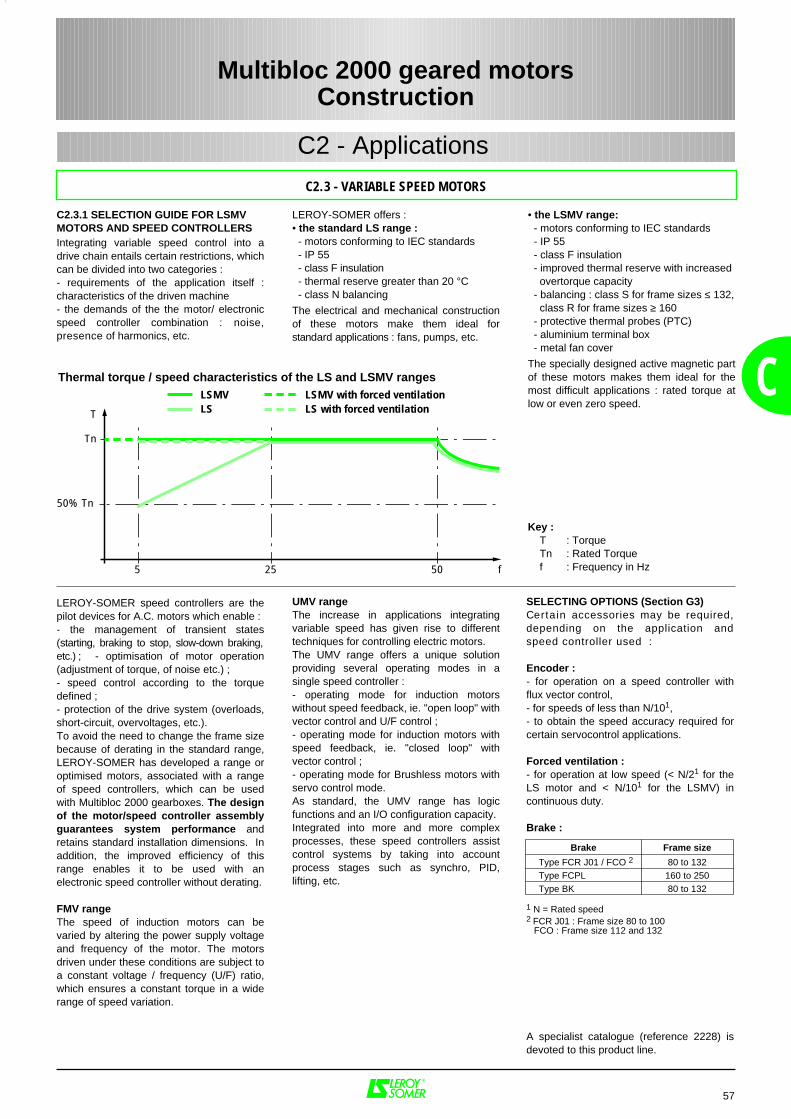
50% Tn
Tn
5 25 50 f
T LSLSMV
LS with forced ventilationLSMV with forced ventilation C
C2.3 - VARIABLE SPEED MOTORS
Multibloc 2000 geared motorsConstruction
C2 - Applications
C2.3.1 SELECTION GUIDE FOR LSMVMOTORS AND SPEED CONTROLLERSIntegrating variable speed control into adrive chain entails certain restrictions, whichcan be divided into two categories :- requirements of the application itself :characteristics of the driven machine- the demands of the the motor/ electronicspeed controller combination : noise,presence of harmonics, etc.
Thermal torque / speed characteristics of the LS and LSMV ranges
LEROY-SOMER offers :• the standard LS range : - motors conforming to IEC standards - IP 55 - class F insulation - thermal reserve greater than 20 °C - class N balancing
The electrical and mechanical constructionof these motors make them ideal forstandard applications : fans, pumps, etc.
• the LSMV range: - motors conforming to IEC standards - IP 55 - class F insulation - improved thermal reserve with increased overtorque capacity - balancing : class S for frame sizes ≤ 132, class R for frame sizes ≥ 160 - protective thermal probes (PTC) - aluminium terminal box - metal fan cover
The specially designed active magnetic partof these motors makes them ideal for themost difficult applications : rated torque atlow or even zero speed.
SELECTING OPTIONS (Section G3)Certain accessories may be required,depending on the application andspeed controller used :
Encoder :- for operation on a speed controller withflux vector control,- for speeds of less than N/101,- to obtain the speed accuracy required forcertain servocontrol applications.
Forced ventilation :- for operation at low speed (< N/21 for theLS motor and < N/101 for the LSMV) incontinuous duty.
Brake :
1 N = Rated speed2 FCR J01 : Frame size 80 to 100 FCO : Frame size 112 and 132
A specialist catalogue (reference 2228) isdevoted to this product line.
Brake Frame size
Type FCR J01 / FCO 2 80 to 132 Type FCPL 160 to 250 Type BK 80 to 132
57
Key : T : Torque Tn : Rated Torque f : Frequency in Hz
LEROY-SOMER speed controllers are thepilot devices for A.C. motors which enable :- the management of transient states(starting, braking to stop, slow-down braking,etc.) ; - optimisation of motor operation(adjustment of torque, of noise etc.) ;- speed control according to the torquedefined ;- protection of the drive system (overloads,short-circuit, overvoltages, etc.).To avoid the need to change the frame sizebecause of derating in the standard range,LEROY-SOMER has developed a range oroptimised motors, associated with a rangeof speed controllers, which can be usedwith Multibloc 2000 gearboxes. The designof the motor/speed controller assemblyguarantees system performance andretains standard installation dimensions. Inaddition, the improved efficiency of thisrange enables it to be used with anelectronic speed controller without derating.
FMV rangeThe speed of induction motors can bevaried by altering the power supply voltageand frequency of the motor. The motorsdriven under these conditions are subject toa constant voltage / frequency (U/F) ratio,which ensures a constant torque in a widerange of speed variation.
UMV rangeThe increase in applications integratingvariable speed has given rise to differenttechniques for controlling electric motors.The UMV range offers a unique solutionproviding several operating modes in asingle speed controller :- operating mode for induction motorswithout speed feedback, ie. "open loop" withvector control and U/F control ;- operating mode for induction motors withspeed feedback, ie. "closed loop" withvector control ;- operating mode for Brushless motors withservo control mode.As standard, the UMV range has logicfunctions and an I/O configuration capacity.Integrated into more and more complexprocesses, these speed controllers assistcontrol systems by taking into accountprocess stages such as synchro, PID,lifting, etc.
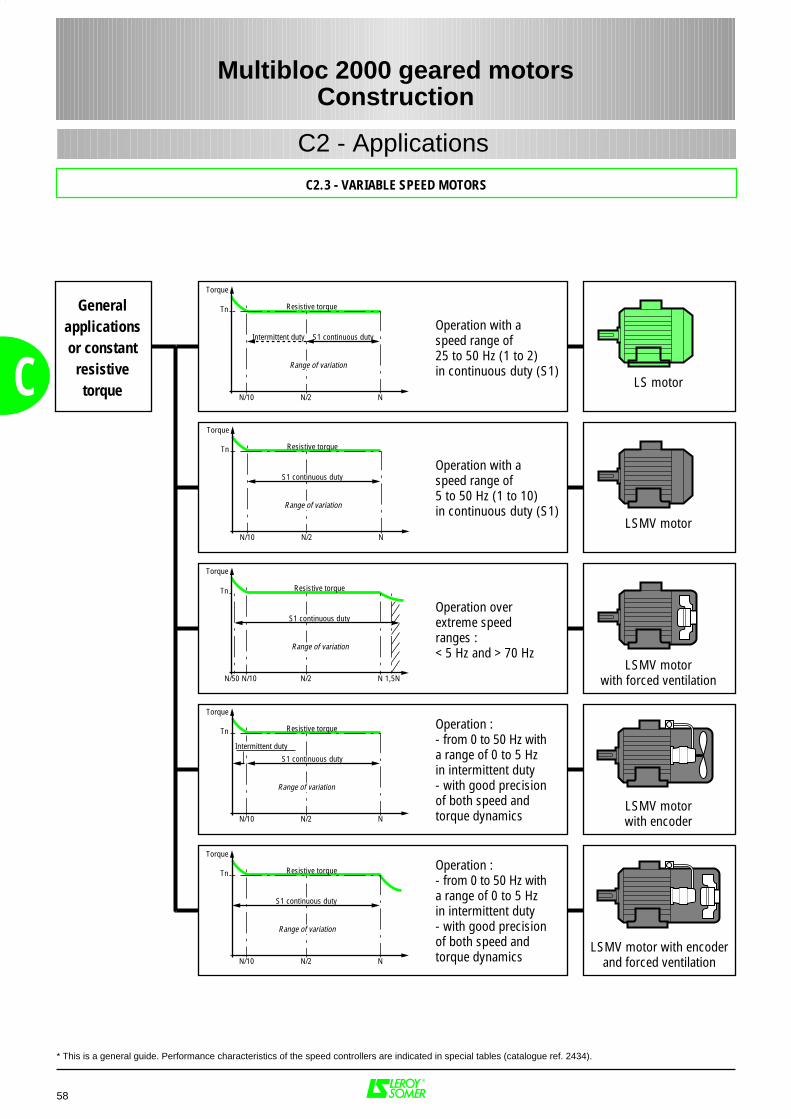
C2.3 - VARIABLE SPEED MOTORS
Generalapplicationsor constant
resistivetorque
Operation :- from 0 to 50 Hz witha range of 0 to 5 Hzin intermittent duty- with good precisionof both speed andtorque dynamics
Operation with a speed range of5 to 50 Hz (1 to 10)in continuous duty (S1)
Operation with aspeed range of25 to 50 Hz (1 to 2)in continuous duty (S1)
LS motor
LSMV motor
LSMV motorwith forced ventilation
LSMV motorwith encoder
LSMV motor with encoderand forced ventilation
Operation overextreme speedranges :< 5 Hz and > 70 Hz
Operation :- from 0 to 50 Hz witha range of 0 to 5 Hzin intermittent duty- with good precisionof both speed andtorque dynamics
Tn
N/10 N/2 N
Torque
S1 continuous duty
Range of variation
Resistive torque
Tn
N/10 N/2 N
Torque
S1 continuous duty
Intermittent duty
Resistive torque
Range of variation
Tn
N/10N/50 N/2 N 1,5N
Torque
S1 continuous duty
Resistive torque
Range of variation
Tn
N/10 N/2 N
Torque
S1 continuous duty
Resistive torque
Range of variation
Tn
N/10 N/2 N
Torque
S1 continuous dutyIntermittent duty
Resistive torque
Range of variation
58
C
Multibloc 2000 geared motorsConstruction
* This is a general guide. Performance characteristics of the speed controllers are indicated in special tables (catalogue ref. 2434).
C2 - Applications

59
C
C2.3.2 MOTOR COMPONENTS
Component Materials Remarks
Finned housing Aluminium alloy - with integral feet, detachable feet or without feet- pressure die-cast for frame sizes ≤ 180- gravity-cast for frame sizes ≥ 200
• 4 or 6 screw holes for foot mounting• lifting rings for frame sizes ≥ 160, optional on 132 and 112
- optional earth terminal
Stator Insulated low-carbon magnetic steellaminations
Electro-plated copper
- low carbon content guarantees long-term lamination pack stability- welded packs- semi-enclosed slots- magnetic circuit which makes use of experience gained in frequency variation- impregnation offers resistance against sudden voltage variations caused by high switching frequencies of IGBT transistor speed controllers in accordance with IEC 34-17- class F insulation- thermal protection provided by 3 PTC probes (1 per phase)
Rotor Insulated low-carbon magnetic steellaminationsAluminium (A5L)
- inclined cage bars- rotor cage pressure die-cast in aluminium (or alloy for special applications)- shrink-fitted to shaft, and keyed for hoisting applications- dynamically balanced rotor, class S or R depending on frame size
Shaft Steel
End shields Cast iron - 80 to 315
Bearings and lubrication - ball bearings C3 play- non-drive end bearings preloaded- greased for life up to and including frame size 180 inclusive- semi-protected or open types from frame size 200 upwards- regreaseable open types from frame size 225 upwards
Labyrinth seals Lipseals
Plastic or steelSynthetic rubber
- lipseal or deflector on DE for all flange motors- lipseal, deflector or labyrinth seal for foot-mounted motors
Fan Composite material - 2 directions of rotation : straight blades
Fan cover Steel - fitted, on request, with a drip cover for operation in vertical position, shaft end facing down.
Terminal box Aluminium alloy - fitted with a terminal block with 8 steel terminals as standard (brass terminal optional)- terminal box supplied with cable gland fitted- 1 earth terminal in each terminal box
1
2
3
4
5
6
7
10
8
9
Multibloc 2000 geared motorsConstruction
C2.3 - VARIABLE SPEED MOTORS
7
2
4
3
9
10
5
8
1
C2 - Applications
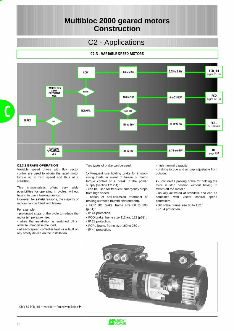
NORMAL
FCOpages 52-164
FCR J01pages 51-164
0.75 to 9 kW
4 to 7.5 kW
0.75 to 3 kW
BRAKE
100 to 132
FRAME SIZE
LOW
160 to 280
80 and 90
80 to 132
INERTIA
USEFCPL
not relevant11 to 90 kW
EMERGENCYSTOP
FREQUENTUSE
PARKINGOCCASIONAL
USEBK
page 224
60
C
Multibloc 2000 geared motorsConstruction
C2.3 - VARIABLE SPEED MOTORS
C2 - Applications
Two types of brake can be used :
1- Frequent use holding brake for immob-ilising loads in event of failure of motortorque control or a break in the powersupply (section C2.2.4) :- can be used for frequent emergency stopsfrom high speed,- option of anti-corrosion treatment ofbraking surfaces (humid environment),• FCR J01 brake, frame size 80 to 100(p.51) :- IP 44 protection.• FCO brake, frame size 112 and 132 (p52) :- IP 23 protection.• FCPL brake, frame size 160 to 280 :- IP 44 protection,
- high thermal capacity,- braking torque and air gap adjustable fromoutside.
2- Low inertia parking brake for holding therotor in stop position without having toswitch off the motor :- usually activated at standstill and can becombined with vector control speedcontrollers. • BK brake, frame size 80 to 132 :- IP 54 protection.
C2.3.3 BRAKE OPERATIONVariable speed drives with flux vectorcontrol are used to obtain the rated motortorque up to zero speed and thus at astandstill.
This characteristic offers very widepossibilities for operating in cycles, withouthaving to use a braking device. However, for safety reasons, the majority ofmotors can be fitted with brakes.
For example :- prolonged stops of the cycle to reduce themotor temperature rise,- while the installation is switched off inorder to immobilise the load,- at each speed controller fault or a fault onany safety device on the installation.
LSMV 80 FCR J01 + encoder + forced ventilation
61
D
Multibloc 2000 geared motorsOperation
D1 - Gearbox 62
D1.1 - Definition of the duty factor required for the application ......................................................... 62
D1.1.1 - Determining duty factor K1 .................................................................................... 62
D1.1.2 - Determining duty factor K2 .................................................................................... 63
D1.2 - Maximum permissible torque .................................................................................................. 63
D1.3 - Thermal power ........................................................................................................................ 64
D1.4 - Radial load............................................................................................................................... 65
D1.4.1 - Radial force on input shaft...................................................................................... 65
D1.4.2 - Radial force on output shaft ................................................................................... 65-66
D1.4.3 - Radial force on standard left or right output shaft .................................................. 67
D1.4.4 - Radial force on standard output shaft with flange................................................... 68
D1.5 - Axial load ................................................................................................................................ 69
D1.5.1 - Axial force on output shaft - Multibloc 3101 - 2201 ................................................ 70
D1.5.2 - Axial force on output shaft - Multibloc 2301 - 2401 ................................................ 71
D1.5.3 - Axial force on output shaft - Multibloc 2501 - 2601 ................................................ 72
D1.6 - Efficiency and reversibility ...................................................................................................... 73
D1.6.1 - Angular play on the output shaft ............................................................................ 73
D1.6.2 - Efficiency ............................................................................................................... 73
D1.6.3 - Reversibility ........................................................................................................... 73
D1.6.4 - Running-in the gearbox ......................................................................................... 73
D2 - Applications 74
D2.1 - Definition of duty types ........................................................................................................................... 74
D2.1.1 - Motors .................................................................................................................................. 74-78
D2.1.2 - Brake motors ........................................................................................................................ 79-80
D2.2 - Supply voltage ........................................................................................................................ 81
D2.2.1 - Regulations and standards .................................................................................... 81-82
D2.2.2 - Effects on motor performance ............................................................................... 83
D2.3 - Insulation class - Temperature rise and thermal reserve ....................................................... 84
D2.4 - Machine vibration level ........................................................................................................... 85-86
D2.5 - Thermal protection .................................................................................................................. 87
PAGES
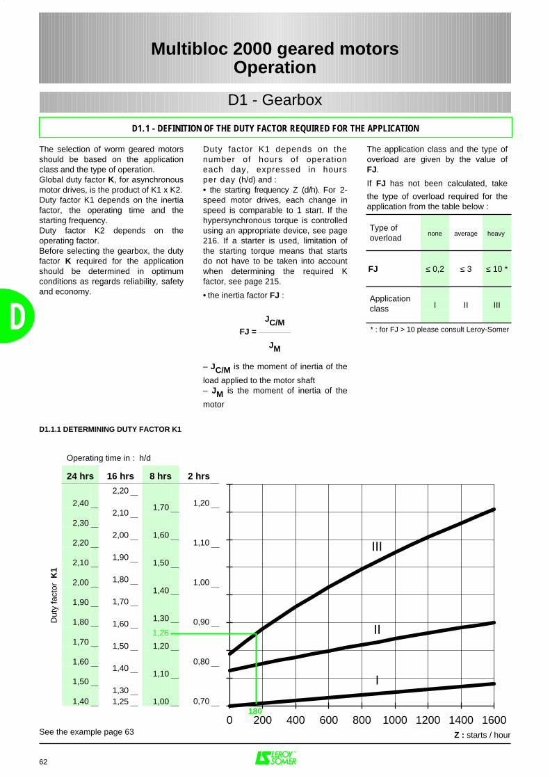
Duty factor K1 depends on thenumber of hours of operationeach day, expressed in hoursper day (h/d) and :• the starting frequency Z (d/h). For 2-speed motor drives, each change inspeed is comparable to 1 start. If thehypersynchronous torque is controlledusing an appropriate device, see page216. If a starter is used, limitation ofthe starting torque means that startsdo not have to be taken into accountwhen determining the required Kfactor, see page 215.
• the inertia factor FJ :
– JC/M is the moment of inertia of the
load applied to the motor shaft– JM is the moment of inertia of the
motor
The selection of worm geared motorsshould be based on the applicationclass and the type of operation.Global duty factor K, for asynchronousmotor drives, is the product of K1 x K2.Duty factor K1 depends on the inertiafactor, the operating time and thestarting frequency.Duty factor K2 depends on theoperating factor.Before selecting the gearbox, the dutyfactor K required for the applicationshould be determined in optimumconditions as regards reliability, safetyand economy.
62
D JC/MFJ =
JM
Dut
y fa
ctor
K1
0 200 400 600 800 1000 1200 1400 16000
1,20
1,10
1,00
0,90
0,80
0,70
1,70
1,60
1,50
1,40
1,30
1,20
1,10
1,00
2,20
2,10
2,00
1,90
1,80
1,70
1,60
1,50
1,40
1,301,25
2,40
2,30
2,20
2,10
2,00
1,90
1,80
1,70
1,60
1,50
1,40
Operating time in : h/d
24 hrs 16 hrs 8 hrs 2 hrs
Z : starts / hour
II
III
I
The application class and the type ofoverload are given by the value ofFJ.
If FJ has not been calculated, take
the type of overload required for theapplication from the table below :
1,26
180
See the example page 63
Multibloc 2000 geared motorsOperation
D1 - Gearbox
D1.1 - DEFINITION OF THE DUTY FACTOR REQUIRED FOR THE APPLICATION
none average heavy
FJ ≤ 0,2 ≤ 3 ≤ 10 *
I II III
* : for FJ > 10 please consult Leroy-Somer
Type ofoverload
Applicationclass
D1.1.1 DETERMINING DUTY FACTOR K1
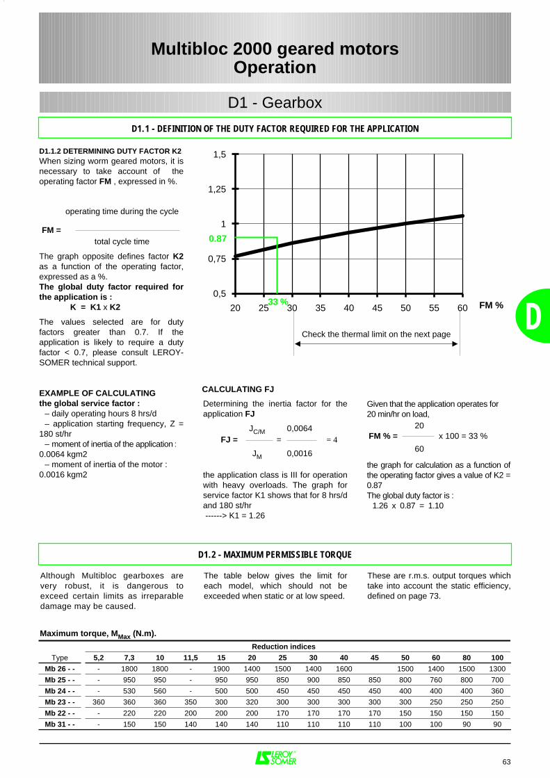
Determining the inertia factor for theapplication FJ
the application class is III for operationwith heavy overloads. The graph forservice factor K1 shows that for 8 hrs/dand 180 st/hr ------> K1 = 1.26
EXAMPLE OF CALCULATINGthe global service factor :
– daily operating hours 8 hrs/d– application starting frequency, Z =
180 st/hr– moment of inertia of the application :
0.0064 kgm2– moment of inertia of the motor :
0.0016 kgm2
Given that the application operates for 20 min/hr on load,
the graph for calculation as a function ofthe operating factor gives a value of K2 =0.87The global duty factor is :
1.26 x 0.87 = 1.10
63
D
JC/M 0,0064FJ = = = 4
JM 0,0016
20FM % = x 100 = 33 %
60
D1.1.2 DETERMINING DUTY FACTOR K2 When sizing worm geared motors, it isnecessary to take account of theoperating factor FM , expressed in %.
The graph opposite defines factor K2as a function of the operating factor,expressed as a %. The global duty factor required forthe application is :
K = K1 x K2
The values selected are for dutyfactors greater than 0.7. If theapplication is likely to require a dutyfactor < 0.7, please consult LEROY-SOMER technical support.
operating time during the cycle
FM =total cycle time
FM %20 25 30 35 40 45 50 55 60
0,5
0,75
1
1,25
1,5
Check the thermal limit on the next page
Maximum torque, MMax (N.m).
Reduction indices
Type 5,2 7,3 10 11,5 15 20 25 30 40 45 50 60 80 100
Mb 26 - - - 1800 1800 - 1900 1400 1500 1400 1600 1500 1400 1500 1300
Mb 25 - - - 950 950 - 950 950 850 900 850 850 800 760 800 700
Mb 24 - - - 530 560 - 500 500 450 450 450 450 400 400 400 360
Mb 23 - - 360 360 360 350 300 320 300 300 300 300 300 250 250 250
Mb 22 - - - 220 220 200 200 200 170 170 170 170 150 150 150 150
Mb 31 - - - 150 150 140 140 140 110 110 110 110 100 100 90 90
Although Multibloc gearboxes arevery robust, it is dangerous toexceed certain limits as irreparabledamage may be caused.
The table below gives the limit foreach model, which should not beexceeded when static or at low speed.
These are r.m.s. output torques whichtake into account the static efficiency,defined on page 73.
CALCULATING FJ
0.87
33 %
D1.1 - DEFINITION OF THE DUTY FACTOR REQUIRED FOR THE APPLICATION
Multibloc 2000 geared motorsOperation
D1 - Gearbox
D1.2 - MAXIMUM PERMISSIBLE TORQUE
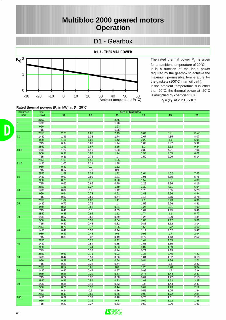
64
D
0 10 20 30 40 50 600-10-20-30
0
1
2
0
Kθθθθ
Size of Multibloc31 22 23 24 25 26
2850 2.755 1430 1.98
950 1.63715 1.35
2850 2.23 1.86 2.43 3.64 6.41 10.457.3 1430 1.46 1.33 1.74 2.67 4.85 8.07
950 1.15 1.08 1.42 2.22 4.1 6.91715 0.94 0.87 1.14 1.83 3.47 5.92
2850 1.99 1.67 2.15 3.2 5.62 9.2410.3 1430 1.22 1.19 1.53 2.33 4.21 7.06
950 0.98 0.97 1.24 1.93 3.55 6.02715 0.81 0.78 1 1.59 2.99 5.14
2850 1.63 1.56 1.9511.5 1430 1.05 1.11 1.38
950 0.80 0.9 1.12715 0.67 0.73 0.9
2850 1.39 1.39 1.72 2.64 4.52 7.6315 1430 0.92 0.99 1.21 1.91 3.35 5.76
950 0.75 0.8 0.98 1.57 2.81 4.89715 0.60 0.65 0.79 1.29 2.36 4.16
2850 1.21 1.27 1.59 2.39 4.11 6.9420 1430 0.82 0.9 1.12 1.73 3.05 5.23
950 0.64 0.73 0.91 1.43 2.56 4.44715 0.52 0.59 0.74 1.18 2.15 3.78
2850 1.07 1.07 1.41 2.1 3.73 6.3925 1430 0.70 0.76 1 1.52 2.76 4.81
950 0.56 0.62 0.81 1.26 2.31 4.09715 0.46 0.5 0.65 1.64 1.95 3.49
2850 0.83 0.92 1.12 1.74 3.1 5.7730 1430 0.57 0.65 0.79 1.25 2.29 4.34
950 0.44 0.53 0.64 1.03 1.92 3.68715 0.37 0.43 0.52 0.85 1.62 3.14
2850 0.70 0.77 1.05 1.55 2.72 4.6240 1430 0.48 0.55 0.74 1.12 2.02 3.47
950 0.39 0.45 0.6 0.93 1.7 2.94715 0.33 0.37 0.49 0.77 1.43 2.52
2850 0.75 0.92 1.44 2.5545 1430 0.54 0.65 1.05 1.89
950 0.44 0.53 0.87 1.59715 0.36 0.44 0.72 1.35
2850 0.63 0.71 0.93 1.38 2.45 4.2250 1430 0.44 0.51 0.66 1.01 1.82 3.18
950 0.38 0.42 0.54 0.84 1.54 2.71715 0.29 0.34 0.44 0.7 1.3 2.32
2850 0.57 0.66 0.8 1.25 2.28 3.8460 1430 0.40 0.47 0.57 0.92 1.7 2.9
950 0.35 0.39 0.47 0.76 1.44 2.47715 0.27 0.32 0.38 0.64 1.22 2.13
2850 0.49 0.59 0.73 1.08 1.92 3.2580 1430 0.35 0.43 0.53 0.8 1.44 2.47
950 0.28 0.36 0.44 0.67 1.23 2.12715 0.24 0.3 0.36 0.56 1.05 1.84
2850 0.43 0.53 0.66 0.98 1.72 2.84100 1430 0.32 0.39 0.48 0.73 1.31 2.18
950 0.26 0.32 0.4 0.62 1.12 1.88715 0.22 0.27 0.33 0.52 0.96 1.63
Rated thermal powers (Pt in kW) at θθθθ = 20°CReduction
indexInputspeed
Multibloc 2000 geared motorsOperation
D1.3 - THERMAL POWER
D1 - Gearbox
Ambient temperature θ (°C)
The rated thermal power Pt is given
for an ambient temperature of 20°C.It is a function of the input powerrequired by the gearbox to achieve themaximum permissible temperature forthe gaskets (100°C in an oil bath).If the ambient temperature θ is otherthan 20°C, the thermal power at 20°Cis multiplied by coefficient Kθ :
Pt = (Pt at 20° C) x Kθ

D1.4.1 RADIAL FORCE ON INPUT SHAFTThe input shaft of gearboxes driven bya motor other than via a semi-flexiblecoupling is subject to a radial force.
D1.4.2 RADIAL FORCE ON OUTPUTSHAFTAll gearboxes and geared motors,connected to the load other than via asemi-flexible coupling, are subject to aradial force F approximately equal to :
F = (MuS / rp ) x δδδδ
where F is expressed in N, MuS is
the torque required by the applicationin N.m and rp the geometrical radius
of the pulley or pinion in m.Factor δ (see table) depends on thetransmission type.
The table below gives the minimumdiameter of the drive to be installed halfway along the input shaft of gearboxEB/2. Only the Mb 31, with a B14 F85input flange integral to the frame, canonly be driven by a motor.
The permissible radial force FR for a
gearbox is calculated using :– the life of the bearings– the mechanical resistance of the shaftand other partsIt always depends on :– the configuration of the output shaft(with or without output flange)– the distance between the shoulder ofthe shaft and the point where the forceis applied
– the speed of rotation of the shaftIt also depends on :
– the direction of rotation of the shaft– the output torque– the direction of the force– the reduction ratio
The tables on pages 67 and 68 give thepermissible radial force FR half way
along the output shaft, with shaftconfigurations G, D, or X, the least favourable. Thus Leroy Somergearboxes will in many casestolerate considerably larger loads.Please consult Leroy Somer technicalsupport for optimised values, giving theactual values mentioned above andusing the diagrams below as areference.
65
D
Drive diameter in millimetresSize of Multibloc
Type 26 25 24 23 22
Ø chain sprocket 200 100 83 67 40Ø toothed belt pulley 133 110 92 73 44Ø gear pinion 147 125 104 83 50Ø V-belt pulley 167 150 125 100 60Ø flat-belt pulley 200 250 208 167 100Ø variable pulley 333 350 292 233 140
Type of drive δ
Chain sprocket 1Toothed belt pulley 1,1Gear pinion 1,25V-belt pulley 1,5Flat-belt pulley 2,5Variable pulley 3,5
Values of δδδδ
Direction of rotation and directionof radial force F :
E
E/2
FR F
90°
270°
0° 180°
+1 -1
90°
270°
0°180°
+1-1 α
Fr
EB
Multibloc 2000 geared motorsOperation
D1.4 - RADIAL LOAD
D1 - Gearbox
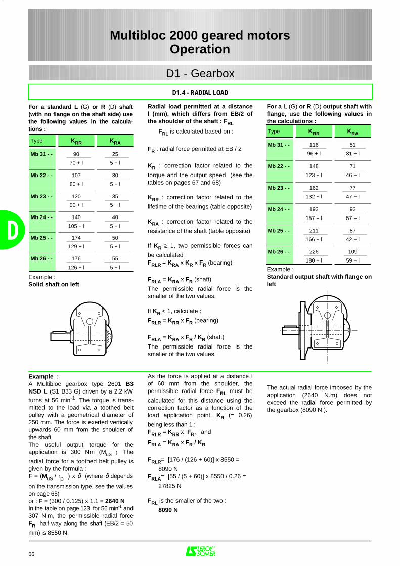
For a standard L (G) or R (D) shaft(with no flange on the shaft side) usethe following values in the calcula-tions :
Example :Solid shaft on left
Example :A Multibloc gearbox type 2601 B3NSD L (S1 B33 G) driven by a 2.2 kWturns at 56 min-1. The torque is trans-mitted to the load via a toothed beltpulley with a geometrical diameter of250 mm. The force is exerted verticallyupwards 60 mm from the shoulder ofthe shaft.The useful output torque for theapplication is 300 Nm (MuS ). The
radial force for a toothed belt pulley isgiven by the formula :F = (MuS / rp ) x δ (where δ depends
on the transmission type, see the valueson page 65)or : F = (300 / 0.125) x 1.1 = 2640 NIn the table on page 123 for 56 min-1 and307 N.m, the permissible radial forceFR half way along the shaft (EB/2 = 50
mm) is 8550 N.
Radial load permitted at a distancel (mm), which differs from EB/2 ofthe shoulder of the shaft : FRL
FRL is calculated based on :
FR : radial force permitted at EB / 2
KR : correction factor related to the
torque and the output speed (see thetables on pages 67 and 68)
KRR : correction factor related to the
lifetime of the bearings (table opposite)
KRA : correction factor related to the
resistance of the shaft (table opposite)
If KR ≥ 1, two permissible forces can
be calculated :FRLR = KRA x KR x FR (bearing)
FRLA = KRA x FR (shaft)
The permissible radial force is thesmaller of the two values.
If KR < 1, calculate :
FRLR = KRR x FR (bearing)
FRLA = KRA x FR / KR (shaft)
The permissible radial force is thesmaller of the two values.
As the force is applied at a distance lof 60 mm from the shoulder, thepermissible radial force FRL must be
calculated for this distance using thecorrection factor as a function of theload application point, KR (= 0.26)
being less than 1 :FRLR = KRR x FR, and
FRLA = KRA x FR / KR
FRLR= [176 / (126 + 60)] x 8550 =
8090 NFRLA= [55 / (5 + 60)] x 8550 / 0.26 =
27825 N
FRL is the smaller of the two :
8090 N
For a L (G) or R (D) output shaft withflange, use the following values inthe calculations :
Example :Standard output shaft with flange onleft
The actual radial force imposed by theapplication (2640 N.m) does notexceed the radial force permitted bythe gearbox (8090 N ).
66
D
Type KRR KRA
Mb 31 - - 90 25
70 + l 5 + l
Mb 22 - - 107 30
80 + l 5 + l
Mb 23 - - 120 35
90 + l 5 + l
Mb 24 - - 140 40
105 + l 5 + l
Mb 25 - - 174 50
129 + l 5 + l
Mb 26 - - 176 55
126 + l 5 + l
Type KRR KRA
Mb 31 - - 116 51
96 + l 31 + l
Mb 22 - - 148 71
123 + l 46 + l
Mb 23 - - 162 77
132 + l 47 + l
Mb 24 - - 192 92
157 + l 57 + l
Mb 25 - - 211 87
166 + l 42 + l
Mb 26 - - 226 109
180 + l 59 + l
Multibloc 2000 geared motorsOperation
D1.4 - RADIAL LOAD
D1 - Gearbox
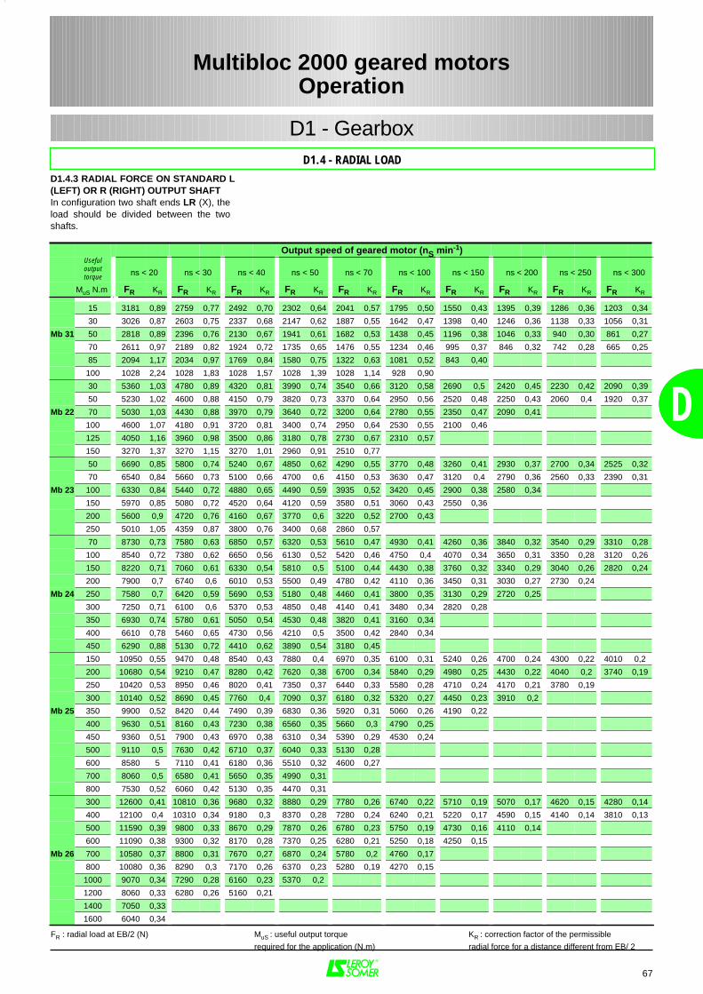
67
D
Output speed of geared motor (nS min-1)Usefuloutputtorque ns < 20 ns < 30 ns < 40 ns < 50 ns < 70 ns < 100 ns < 150 ns < 200 ns < 250 ns < 300
MuS N.m FR KR FR KR FR KR FR KR FR KR FR KR FR KR FR KR FR KR FR KR
15 3181 0,89 2759 0,77 2492 0,70 2302 0,64 2041 0,57 1795 0,50 1550 0,43 1395 0,39 1286 0,36 1203 0,34
30 3026 0,87 2603 0,75 2337 0,68 2147 0,62 1887 0,55 1642 0,47 1398 0,40 1246 0,36 1138 0,33 1056 0,31
Mb 31 50 2818 0,89 2396 0,76 2130 0,67 1941 0,61 1682 0,53 1438 0,45 1196 0,38 1046 0,33 940 0,30 861 0,27
70 2611 0,97 2189 0,82 1924 0,72 1735 0,65 1476 0,55 1234 0,46 995 0,37 846 0,32 742 0,28 665 0,25
85 2094 1,17 2034 0,97 1769 0,84 1580 0,75 1322 0,63 1081 0,52 843 0,40
100 1028 2,24 1028 1,83 1028 1,57 1028 1,39 1028 1,14 928 0,90
30 5360 1,03 4780 0,89 4320 0,81 3990 0,74 3540 0,66 3120 0,58 2690 0,5 2420 0,45 2230 0,42 2090 0,39
50 5230 1,02 4600 0,88 4150 0,79 3820 0,73 3370 0,64 2950 0,56 2520 0,48 2250 0,43 2060 0,4 1920 0,37
Mb 22 70 5030 1,03 4430 0,88 3970 0,79 3640 0,72 3200 0,64 2780 0,55 2350 0,47 2090 0,41
100 4600 1,07 4180 0,91 3720 0,81 3400 0,74 2950 0,64 2530 0,55 2100 0,46
125 4050 1,16 3960 0,98 3500 0,86 3180 0,78 2730 0,67 2310 0,57
150 3270 1,37 3270 1,15 3270 1,01 2960 0,91 2510 0,77
50 6690 0,85 5800 0,74 5240 0,67 4850 0,62 4290 0,55 3770 0,48 3260 0,41 2930 0,37 2700 0,34 2525 0,32
70 6540 0,84 5660 0,73 5100 0,66 4700 0,6 4150 0,53 3630 0,47 3120 0,4 2790 0,36 2560 0,33 2390 0,31
Mb 23 100 6330 0,84 5440 0,72 4880 0,65 4490 0,59 3935 0,52 3420 0,45 2900 0,38 2580 0,34
150 5970 0,85 5080 0,72 4520 0,64 4120 0,59 3580 0,51 3060 0,43 2550 0,36
200 5600 0,9 4720 0,76 4160 0,67 3770 0,6 3220 0,52 2700 0,43
250 5010 1,05 4359 0,87 3800 0,76 3400 0,68 2860 0,57
70 8730 0,73 7580 0,63 6850 0,57 6320 0,53 5610 0,47 4930 0,41 4260 0,36 3840 0,32 3540 0,29 3310 0,28
100 8540 0,72 7380 0,62 6650 0,56 6130 0,52 5420 0,46 4750 0,4 4070 0,34 3650 0,31 3350 0,28 3120 0,26
150 8220 0,71 7060 0,61 6330 0,54 5810 0,5 5100 0,44 4430 0,38 3760 0,32 3340 0,29 3040 0,26 2820 0,24
200 7900 0,7 6740 0,6 6010 0,53 5500 0,49 4780 0,42 4110 0,36 3450 0,31 3030 0,27 2730 0,24
Mb 24 250 7580 0,7 6420 0,59 5690 0,53 5180 0,48 4460 0,41 3800 0,35 3130 0,29 2720 0,25
300 7250 0,71 6100 0,6 5370 0,53 4850 0,48 4140 0,41 3480 0,34 2820 0,28
350 6930 0,74 5780 0,61 5050 0,54 4530 0,48 3820 0,41 3160 0,34
400 6610 0,78 5460 0,65 4730 0,56 4210 0,5 3500 0,42 2840 0,34
450 6290 0,88 5130 0,72 4410 0,62 3890 0,54 3180 0,45
150 10950 0,55 9470 0,48 8540 0,43 7880 0,4 6970 0,35 6100 0,31 5240 0,26 4700 0,24 4300 0,22 4010 0,2
200 10680 0,54 9210 0,47 8280 0,42 7620 0,38 6700 0,34 5840 0,29 4980 0,25 4430 0,22 4040 0,2 3740 0,19
250 10420 0,53 8950 0,46 8020 0,41 7350 0,37 6440 0,33 5580 0,28 4710 0,24 4170 0,21 3780 0,19
300 10140 0,52 8690 0,45 7760 0,4 7090 0,37 6180 0,32 5320 0,27 4450 0,23 3910 0,2
Mb 25 350 9900 0,52 8420 0,44 7490 0,39 6830 0,36 5920 0,31 5060 0,26 4190 0,22
400 9630 0,51 8160 0,43 7230 0,38 6560 0,35 5660 0,3 4790 0,25
450 9360 0,51 7900 0,43 6970 0,38 6310 0,34 5390 0,29 4530 0,24
500 9110 0,5 7630 0,42 6710 0,37 6040 0,33 5130 0,28
600 8580 5 7110 0,41 6180 0,36 5510 0,32 4600 0,27
700 8060 0,5 6580 0,41 5650 0,35 4990 0,31
800 7530 0,52 6060 0,42 5130 0,35 4470 0,31
300 12600 0,41 10810 0,36 9680 0,32 8880 0,29 7780 0,26 6740 0,22 5710 0,19 5070 0,17 4620 0,15 4280 0,14
400 12100 0,4 10310 0,34 9180 0,3 8370 0,28 7280 0,24 6240 0,21 5220 0,17 4590 0,15 4140 0,14 3810 0,13
500 11590 0,39 9800 0,33 8670 0,29 7870 0,26 6780 0,23 5750 0,19 4730 0,16 4110 0,14
600 11090 0,38 9300 0,32 8170 0,28 7370 0,25 6280 0,21 5250 0,18 4250 0,15
Mb 26 700 10580 0,37 8800 0,31 7670 0,27 6870 0,24 5780 0,2 4760 0,17
800 10080 0,36 8290 0,3 7170 0,26 6370 0,23 5280 0,19 4270 0,15
1000 9070 0,34 7290 0,28 6160 0,23 5370 0,2
1200 8060 0,33 6280 0,26 5160 0,21
1400 7050 0,33
1600 6040 0,34
FR : radial load at EB/2 (N) MuS : useful output torque KR : correction factor of the permissible
required for the application (N.m) radial force for a distance different from EB/ 2
D1.4 - RADIAL LOAD
Multibloc 2000 geared motorsOperation
D1 - Gearbox
D
D1.4.3 RADIAL FORCE ON STANDARD L(LEFT) OR R (RIGHT) OUTPUT SHAFTIn configuration two shaft ends LR (X), theload should be divided between the twoshafts.
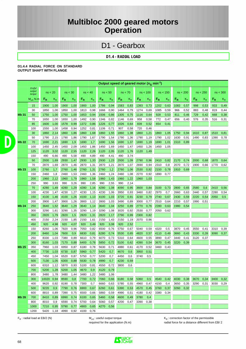
68
D
Output speed of geared motor (nS min-1)Usefuloutputtorque ns < 20 ns < 30 ns < 40 ns < 50 ns < 70 ns < 100 ns < 150 ns < 200 ns < 250 ns < 300
MuS N.m FR KR FR KR FR KR FR KR FR KR FR KR FR KR FR KR FR KR FR KR
15 1900 1,00 1900 1,00 1900 1,00 1786 0,94 1583 0,83 1393 0,73 1202 0,63 1083 0,57 998 0,53 933 0,49
30 1850 1,00 1850 1,00 1813 0,98 1666 0,90 1464 0,79 1274 0,69 1085 0,59 966 0,52 883 0,48 819 0,44
Mb 31 50 1750 1,00 1750 1,00 1653 0,94 1506 0,86 1305 0,75 1116 0,64 928 0,53 811 0,46 729 0,42 668 0,38
70 1650 1,00 1650 1,00 1492 0,90 1346 0,82 1146 0,69 958 0,58 772 0,47 656 0,40 576 0,35 516 0,31
85 1600 1,00 1578 0,99 1372 0,86 1226 0,77 1026 0,64 839 0,52 654 0,41
100 1550 1,00 1458 0,94 1252 0,81 1106 0,71 907 0,58 720 0,46
30 1860 2,14 1860 1,86 1860 1,68 1860 1,55 1860 1,38 1860 1,21 1860 1,05 1750 0,94 1610 0,87 1510 0,81
50 1790 2,15 1790 1,86 1790 1,67 1790 1,54 1790 1,36 1790 1,19 1790 1,02 1630 0,91 1490 0,83 1390 0,78
Mb 22 70 1690 2,21 1690 1,9 1690 1,7 1690 1,56 1690 1,37 1690 1,19 1690 1,01 1510 0,89
100 1450 2,45 1450 2,09 1450 1,86 1450 1,69 1450 1,47 1450 1,26 1450 1,05
125 1120 3,02 1120 2,55 1120 2,26 1120 2,05 1120 1,76 1120 1,49
150 490 6,66 490 5,58 490 4,89 490 4,41 490 3,74
50 2930 1,69 2930 1,47 2930 1,33 2930 1,23 2930 1,09 2790 0,96 2410 0,82 2170 0,74 2000 0,68 1870 0,64
70 2870 1,69 2870 1,46 2870 1,31 2870 1,21 2870 1,07 2690 0,94 2310 0,8 2070 0,72 1900 0,66 1770 0,62
Mb 23 100 2760 1,7 2760 1,46 2760 1,31 2760 1,2 2760 1,06 2530 0,92 2150 0,78 1910 0,69
150 2460 1,8 2460 1,53 2460 1,36 2460 1,24 2460 1,08 2270 0,92 1890 0,77
200 1960 2,12 1960 1,79 1960 1,58 1960 1,43 1960 1,22 1960 1,03
250 990 3,93 990 3,26 990 2,85 990 2,55 990 2,14
70 4280 1,49 4280 1,29 4280 1,16 4280 1,08 4090 0,95 3600 0,84 3100 0,73 2800 0,65 2580 0,6 2410 0,56
100 4230 1,47 4230 1,27 4230 1,15 4230 1,06 3950 0,93 3460 0,82 2970 0,7 2660 0,63 2440 0,57 2280 0,54
150 4100 1,46 4100 1,26 4100 1,13 4100 1,03 3720 0,91 3230 0,79 2740 0,67 2430 0,59 2220 0,54 2050 0,5
200 3900 1,47 3900 1,26 3900 1,12 3900 1,03 3490 0,89 3000 0,77 2510 0,64 2210 0,57 1990 0,51
Mb 24 250 3640 1,52 3640 1,29 3640 1,14 3640 1,04 3250 0,89 2770 0,76 2280 0,63 1980 0,54
300 3290 1,61 3290 1,35 3290 1,19 3290 1,08 3020 0,92 2530 0,77 2050 0,62
350 2820 1,79 2820 1,5 2820 1,31 2820 1,17 2790 0,99 2300 0,82
400 2150 2,24 2150 1,85 2150 1,61 2150 1,43 2150 1,19 2070 0,96
450 920 4,98 920 4,07 920 3,49 920 3,08 920 2,52
150 8260 1,06 7820 0,96 7050 0,82 6500 0,76 5750 0,67 5040 0,59 4320 0,5 3870 0,45 3550 0,41 3310 0,39
200 8460 1,04 7600 0,9 6830 0,81 6280 0,74 5530 0,65 4820 0,57 4110 0,49 3660 0,43 3330 0,39 3090 0,37
250 8330 1,03 7380 0,89 6610 0,79 6070 0,73 5310 0,64 4600 0,55 3890 0,47 3440 0,41 3120 0,37
300 8160 1,03 7170 0,88 6400 0,78 5850 0,72 5100 0,62 4390 0,54 3670 0,45 3220 0,39
Mb 25 350 7960 1,03 6950 0,87 6180 0,78 5630 0,71 4880 0,61 4170 0,52 3460 0,43
400 7730 1,03 6730 0,87 5960 0,77 5420 0,7 4670 0,6 3950 0,51
450 7450 1,04 6520 0,87 5750 0,77 5200 0,7 4450 0,6 3740 0,5
500 7130 1,05 6300 0,88 5530 0,78 4990 0,7 4230 0,59
600 6310 1,12 5870 0,93 5100 0,81 4550 0,72 3800 0,6
700 5200 1,28 5200 1,05 4670 0,9 4120 0,79
800 3480 1,78 3480 1,44 3480 1,22 3480 1,06
300 10020 0,94 8590 0,8 7700 0,72 7060 0,66 6180 0,58 5360 0,5 4540 0,42 4030 0,38 3670 0,34 3400 0,32
400 9620 0,92 8190 0,78 7300 0,7 6660 0,63 5780 0,55 4960 0,47 4150 0,4 3650 0,35 3290 0,31 3030 0,29
500 9220 0,9 7790 0,76 6900 0,67 6260 0,61 5390 0,53 4570 0,45 3760 0,37 3260 0,32
600 8810 0,89 7390 0,75 6500 0,66 5860 0,59 4990 0,51 4180 0,42 3380 0,34
Mb 26 700 8410 0,89 6990 0,74 6100 0,65 5460 0,58 4600 0,49 3780 0,4
800 8010 0,9 6590 0,74 5700 0,64 5060 0,57 4200 0,47 3390 0,38
1000 7210 0,95 5790 0,77 4900 0,65 4270 0,56
1200 5420 1,18 4990 0,92 4100 0,76
FR : radial load at EB/2 (N) MuS : useful output torque KR : correction factor of the permissible
required for the application (N.m) radial force for a distance different from EB/ 2
Multibloc 2000 geared motorsOperation
D1.4 - RADIAL LOAD
D1 - Gearbox
D1.4.4 RADIAL FORCE ON STANDARDOUTPUT SHAFT WITH FLANGE
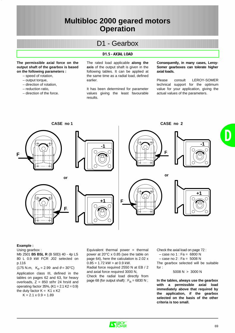
D1 - Gearbox
The permissible axial force on theoutput shaft of the gearbox is basedon the following parameters :
– speed of rotation,– output torque,– direction of rotation,– reduction ratio,– direction of the force.
Example :Using gearbox : Mb 2501 B5 BSL R (B 50D) 40 - 4p LS80 L 0.9 kW FCR J02 selected onp.116(175 N.m, KP = 2.99 and θ = 30°C)
Application class III, defined in thetables on pages 62 and 63, for heavyoverloads, Z = 850 st/hr 24 hrs/d andoperating factor 35%, (K1 = 2.1 K2 = 0.9)the duty factor K = K1 x K2
K = 2.1 x 0.9 = 1.89
The rated load applicable along theaxis of the output shaft is given in thefollowing tables. It can be applied atthe same time as a radial load, definedearlier.
It has been determined for parametervalues giving the least favourableresults.
Equivalent thermal power = thermalpower at 20°C x 0.85 (see the table onpage 64), here the calculation is 2.02 x0.85 = 1.72 kW > at 0.9 kW.Radial force required 2550 N at EB / 2and axial force required 3000 N, Check the radial load directly frompage 68 (for output shaft) : FR = 6830 N ;
Consequently, in many cases, Leroy-Somer gearboxes can tolerate higheraxial loads.
Please consult LEROY-SOMERtechnical support for the optimumvalue for your application, giving theactual values of the parameters.
Check the axial load on page 72 : – case no 1 : Fa = 6800 N– case no 2 : Fa = 5008 N
The gearbox selected will be suitablefor :
5008 N > 3000 N
In the tables, always use the gearboxwith a permissible axial loadimmediately above that required bythe application, if the gearboxselected on the basis of the othercriteria is too small.
69
D
Fa
Fa Fa
Fa
CASE no 1 CASE no 2
oror
-1 -1
+1
+1
Multibloc 2000 geared motorsOperation
D
D1.5 - AXIAL LOAD
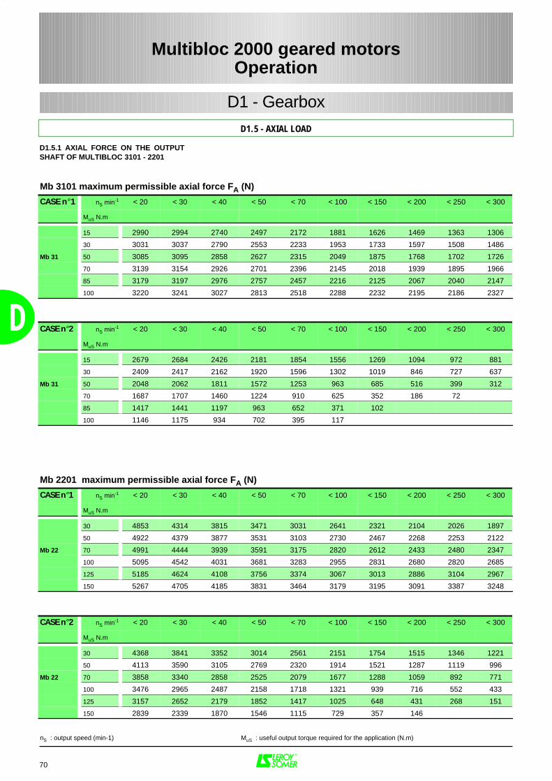
70
D
Mb 3101 maximum permissible axial force FA (N)
CASE n° 1 nS min-1 < 20 < 30 < 40 < 50 < 70 < 100 < 150 < 200 < 250 < 300
MuS N.m
15 2990 2994 2740 2497 2172 1881 1626 1469 1363 1306
30 3031 3037 2790 2553 2233 1953 1733 1597 1508 1486
Mb 31 50 3085 3095 2858 2627 2315 2049 1875 1768 1702 1726
70 3139 3154 2926 2701 2396 2145 2018 1939 1895 1966
85 3179 3197 2976 2757 2457 2216 2125 2067 2040 2147
100 3220 3241 3027 2813 2518 2288 2232 2195 2186 2327
CASE n° 2 nS min-1 < 20 < 30 < 40 < 50 < 70 < 100 < 150 < 200 < 250 < 300
MuS N.m
15 2679 2684 2426 2181 1854 1556 1269 1094 972 881
30 2409 2417 2162 1920 1596 1302 1019 846 727 637
Mb 31 50 2048 2062 1811 1572 1253 963 685 516 399 312
70 1687 1707 1460 1224 910 625 352 186 72
85 1417 1441 1197 963 652 371 102
100 1146 1175 934 702 395 117
Mb 2201 maximum permissible axial force FA (N)
CASE n° 1 nS min-1 < 20 < 30 < 40 < 50 < 70 < 100 < 150 < 200 < 250 < 300
MuS N.m
30 4853 4314 3815 3471 3031 2641 2321 2104 2026 1897
50 4922 4379 3877 3531 3103 2730 2467 2268 2253 2122
Mb 22 70 4991 4444 3939 3591 3175 2820 2612 2433 2480 2347
100 5095 4542 4031 3681 3283 2955 2831 2680 2820 2685
125 5185 4624 4108 3756 3374 3067 3013 2886 3104 2967
150 5267 4705 4185 3831 3464 3179 3195 3091 3387 3248
CASE n° 2 nS min-1 < 20 < 30 < 40 < 50 < 70 < 100 < 150 < 200 < 250 < 300
MuS N.m
30 4368 3841 3352 3014 2561 2151 1754 1515 1346 1221
50 4113 3590 3105 2769 2320 1914 1521 1287 1119 996
Mb 22 70 3858 3340 2858 2525 2079 1677 1288 1059 892 771
100 3476 2965 2487 2158 1718 1321 939 716 552 433
125 3157 2652 2179 1852 1417 1025 648 431 268 151
150 2839 2339 1870 1546 1115 729 357 146
nS : output speed (min-1) MuS : useful output torque required for the application (N.m)
D1.5 - AXIAL LOAD
Multibloc 2000 geared motorsOperation
D1 - Gearbox
D1.5.1 AXIAL FORCE ON THE OUTPUTSHAFT OF MULTIBLOC 3101 - 2201
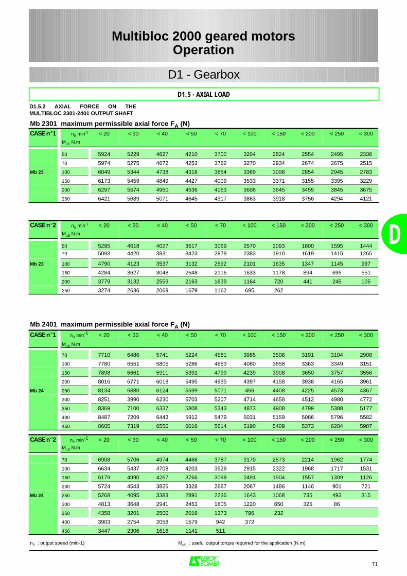
71
D
Mb 2301 maximum permissible axial force FA (N)CASE n° 1 nS min-1 < 20 < 30 < 40 < 50 < 70 < 100 < 150 < 200 < 250 < 300
MuS N.m
50 5924 5229 4627 4210 3700 3204 2824 2554 2495 2336
70 5974 5275 4672 4253 3762 3270 2934 2674 2675 2515
Mb 23 100 6049 5344 4738 4318 3854 3369 3098 2854 2945 2783
150 6173 5459 4849 4427 4009 3533 3371 3155 3395 3229
200 6297 5574 4960 4536 4163 3698 3645 3455 3845 3675
250 6421 5689 5071 4645 4317 3863 3918 3756 4294 4121
CASE n° 2 nS min-1 < 20 < 30 < 40 < 50 < 70 < 100 < 150 < 200 < 250 < 300
MuS N.m
50 5295 4618 4027 3617 3069 2570 2093 1800 1595 144470 5093 4420 3831 3423 2878 2383 1910 1619 1415 1265
Mb 23 100 4790 4123 3537 3132 2592 2101 1635 1347 1145 997
150 4284 3627 3048 2648 2116 1633 1178 894 695 551
200 3779 3132 2559 2163 1639 1164 720 441 245 105
250 3274 2636 2069 1679 1162 695 262
Mb 2401 maximum permissible axial force FA (N)
CASE n° 1 nS min-1 < 20 < 30 < 40 < 50 < 70 < 100 < 150 < 200 < 250 < 300
MuS N.m
70 7710 6486 5741 5224 4581 3985 3508 3191 3104 2908
100 7780 6551 5805 5286 4663 4080 3658 3363 3349 3151
150 7898 6661 5911 5391 4799 4239 3908 3650 3757 3556
200 8016 6771 6018 5495 4935 4397 4158 3938 4165 3961
Mb 24 250 8134 6880 6124 5599 5071 456 4408 4225 4573 4367
300 8251 3990 6230 5703 5207 4714 4658 4512 4980 4772
350 8369 7100 6337 5808 5343 4873 4908 4799 5388 5177
400 8487 7209 6443 5912 5479 5031 5159 5086 5796 5582
450 8605 7319 6550 6016 5614 5190 5409 5373 6204 5987
CASE n° 2 nS min-1 < 20 < 30 < 40 < 50 < 70 < 100 < 150 < 200 < 250 < 300MuS N.m
70 6908 5706 4974 4466 3787 3170 2573 2214 1962 1774
100 6634 5437 4708 4203 3529 2915 2322 1968 1717 1531
150 6179 4990 4267 3766 3098 2491 1904 1557 1309 1126
200 5724 4543 3825 3328 2667 2067 1486 1146 901 721
Mb 24 250 5268 4095 3383 2891 2236 1643 1068 735 493 315
300 4813 3648 2941 2453 1805 1220 650 325 86
350 4358 3201 2500 2016 1373 796 232
400 3903 2754 2058 1579 942 372
450 3447 2306 1616 1141 511
nS : output speed (min-1) MuS : useful output torque required for the application (N.m)
Multibloc 2000 geared motorsOperation
D
D1.5 - AXIAL LOAD
D1 - Gearbox
D1.5.2 AXIAL FORCE ON THEMULTIBLOC 2301-2401 OUTPUT SHAFT
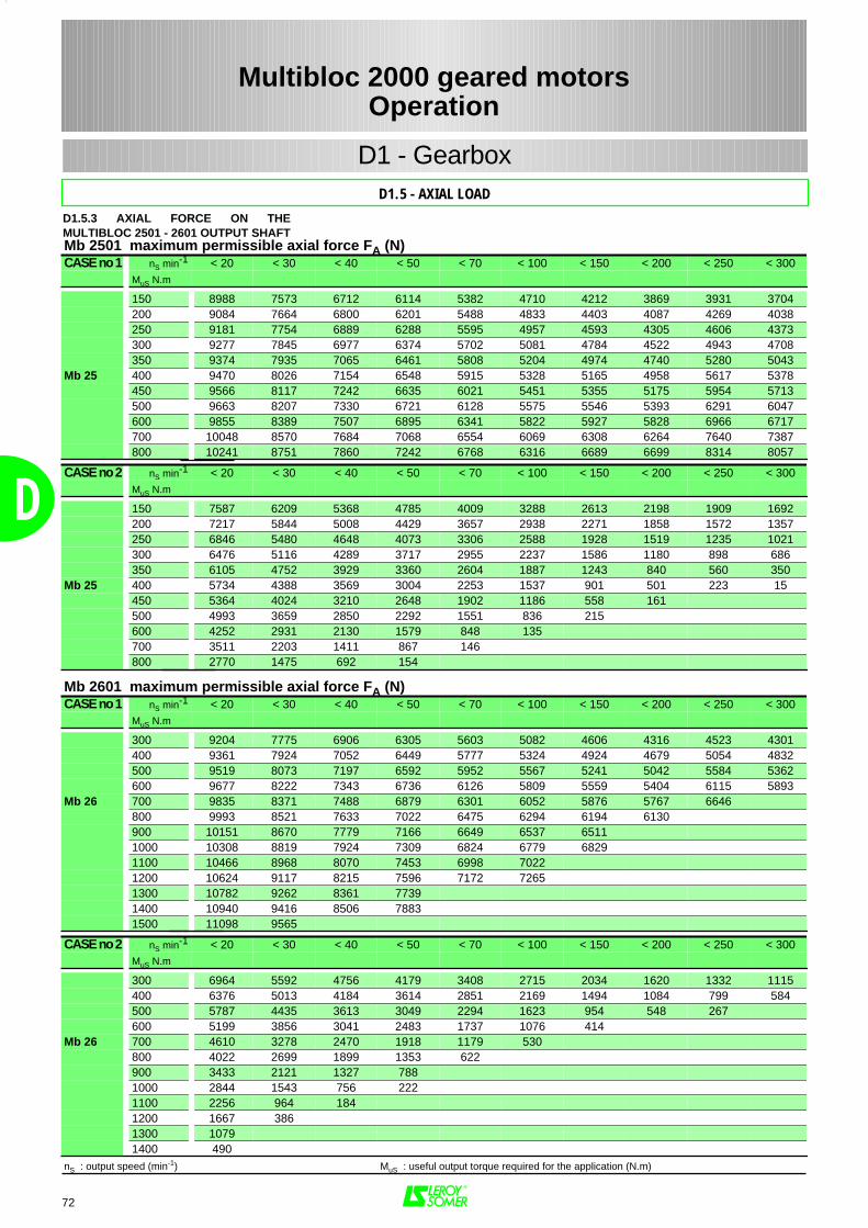
72
D
Mb 2501 maximum permissible axial force FA (N)CASE no 1 nS min-1 < 20 < 30 < 40 < 50 < 70 < 100 < 150 < 200 < 250 < 300
MuS N.m
150 8988 7573 6712 6114 5382 4710 4212 3869 3931 3704200 9084 7664 6800 6201 5488 4833 4403 4087 4269 4038250 9181 7754 6889 6288 5595 4957 4593 4305 4606 4373300 9277 7845 6977 6374 5702 5081 4784 4522 4943 4708350 9374 7935 7065 6461 5808 5204 4974 4740 5280 5043
Mb 25 400 9470 8026 7154 6548 5915 5328 5165 4958 5617 5378450 9566 8117 7242 6635 6021 5451 5355 5175 5954 5713500 9663 8207 7330 6721 6128 5575 5546 5393 6291 6047600 9855 8389 7507 6895 6341 5822 5927 5828 6966 6717700 10048 8570 7684 7068 6554 6069 6308 6264 7640 7387800 10241 8751 7860 7242 6768 6316 6689 6699 8314 8057
CASE no 2 nS min-1 < 20 < 30 < 40 < 50 < 70 < 100 < 150 < 200 < 250 < 300MuS N.m
150 7587 6209 5368 4785 4009 3288 2613 2198 1909 1692200 7217 5844 5008 4429 3657 2938 2271 1858 1572 1357250 6846 5480 4648 4073 3306 2588 1928 1519 1235 1021300 6476 5116 4289 3717 2955 2237 1586 1180 898 686350 6105 4752 3929 3360 2604 1887 1243 840 560 350
Mb 25 400 5734 4388 3569 3004 2253 1537 901 501 223 15450 5364 4024 3210 2648 1902 1186 558 161500 4993 3659 2850 2292 1551 836 215600 4252 2931 2130 1579 848 135700 3511 2203 1411 867 146800 2770 1475 692 154
Mb 2601 maximum permissible axial force FA (N)CASE no 1 nS min-1 < 20 < 30 < 40 < 50 < 70 < 100 < 150 < 200 < 250 < 300
MuS N.m
300 9204 7775 6906 6305 5603 5082 4606 4316 4523 4301400 9361 7924 7052 6449 5777 5324 4924 4679 5054 4832500 9519 8073 7197 6592 5952 5567 5241 5042 5584 5362600 9677 8222 7343 6736 6126 5809 5559 5404 6115 5893
Mb 26 700 9835 8371 7488 6879 6301 6052 5876 5767 6646800 9993 8521 7633 7022 6475 6294 6194 6130900 10151 8670 7779 7166 6649 6537 65111000 10308 8819 7924 7309 6824 6779 68291100 10466 8968 8070 7453 6998 70221200 10624 9117 8215 7596 7172 72651300 10782 9262 8361 77391400 10940 9416 8506 78831500 11098 9565
CASE no 2 nS min-1 < 20 < 30 < 40 < 50 < 70 < 100 < 150 < 200 < 250 < 300MuS N.m
300 6964 5592 4756 4179 3408 2715 2034 1620 1332 1115400 6376 5013 4184 3614 2851 2169 1494 1084 799 584500 5787 4435 3613 3049 2294 1623 954 548 267600 5199 3856 3041 2483 1737 1076 414
Mb 26 700 4610 3278 2470 1918 1179 530800 4022 2699 1899 1353 622900 3433 2121 1327 7881000 2844 1543 756 2221100 2256 964 1841200 1667 3861300 10791400 490
nS : output speed (min-1) MuS : useful output torque required for the application (N.m)
Multibloc 2000 geared motorsOperation
D1.5 - AXIAL LOAD
D1 - Gearbox
D1.5.3 AXIAL FORCE ON THEMULTIBLOC 2501 - 2601 OUTPUT SHAFT

D
(or non-reversibility) is required ormay be harmful, please consultLEROY-SOMER.The three following cases demonstratea simplified approach to thisphenomenon :– a) Reversibility : reductions 5 to 15 ifa torque is applied to the output shaft(of equipment which may or may nothave been run in), the input shaft alsobegins to turn : "backdriving" occurs.– b) Intermittent reversibility :reductions 20, 25, 30, 40. A gearboxwill be reversible or not depending onthe values of the parametersmentioned above. It is highly probablethat it will become reversible, with poorinverse efficiency, after a few hundred
73
D
Size 26 25 24 23 22 31average
play(')
11,5 13,5 21,5 23 27 28
given for information, in minutes ofan angle ('), in the table opposite :
The values of ηηηηs shown below are for
rated operating conditions, i.e. :– equipment completely run in (seebelow, D1.6.4)– appropriate lubricant– stable operating temperature
– load close to rated torque for K = 1
Size of Multibloc26 - - 25 - - 24 - - 23 - - 22 - - 31 - -
5,2 0,727,3 0,69 0,63 0,68 0,910 0,66 0,66 0,65 0,64 0,65 0,87
11,5 0,61 0,63 0,8515 0,6 0,58 0,58 0,56 0,59 0,8320 0,57 0,56 0,56 0,55 0,57 0,825 0,55 0,53 0,52 0,51 0,51 0,7830 0,51 0,44 0,43 0,41 0,44 0,7240 0,42 0,41 0,41 0,4 0,37 0,6845 0,39 0,38 0,34 0,3750 0,4 0,37 0,36 0,35 0,34 0,6460 0,35 0,35 0,33 0,3 0,33 0,6180 0,31 0,3 0,29 0,28 0,3 0,55
100 0,26 0,26 0,26 0,25 0,26 0,5
Reduction index
D1.6.3 REVERSIBILITY
When η s. inv < 0 (or η inv < 0) the
gearbox is said to be statically (ordynamically) non-reversible. Theconcept of reversibility generallyremains purely theoretical since it isbased on too many unknownparameters :– to what degree the gearbox hasbeen run in (the more the gearbox isrun in, the better the reversibility)– lubrication (operating type andtemperature)– inertia of the transmission lines.– amplitude and frequency of vibra-tions to which the gearbox has beensubjected.For all applications where reversibility
hours of operation at rated load (forreductions 20 and 25), or several hun-dred hours (for reductions 30 and 40). – c) Non-reversibility : reductions 50 to100.However much a device has been run in,it will not "backdrive" (from a staticposition) unless the gearbox is subjectedto shocks or vibrations. In this case, assoon as the input shaft starts to turn, thegearbox becomes dynamicallyreversible with very poor inverseefficiency.
D1.6.4 RUNNING-IN THE GEARBOXIn order to increase the lifetime of agearbox, it is advisable to run in themachine (to achieve a perfectalignment of the teeth profiles),especially for applications with factor
K≤ 1. Running-in should be performedat a torque of 0.5 M during a periodof approxiately :– 24 hrs for a gain of η ≈ 3%(reductions 5 to 10)
– 48 hrs for a gain of η ≈ 3 to 7%(reductions 15 to 25)– 48 hrs for a gain of η ≈10 to 15%(reductions 30 to 100)
Multibloc 2000 geared motorsOperation
D1.6 - EFFICIENCY AND REVERSIBILITY
D1 - Gearbox
D1.6.1 ANGULAR PLAY ON THEOUTPUT SHAFTThe standard angular play, measuredon the output shaft (worm locked) is
D1.6.2 EFFICIENCY
The dynamic efficiency ηηηη of the Multi-bloc gearbox is given in the selectiontables.
Static efficiency ηηηηs(starting torque)
Inverse dynamic efficiency ηηηηinv
It is particularly useful to know thisvalue, even approximately, when thewheel acts as a motor : this is generally
the case when braking occurs on theinput shaft.It is calculated approximately using thefollowing formula :
ηηηηinv = 2 - 1 / η
Thus the inverse static efficiency is : ηηηηs. inv = 2 - 1 / ηs
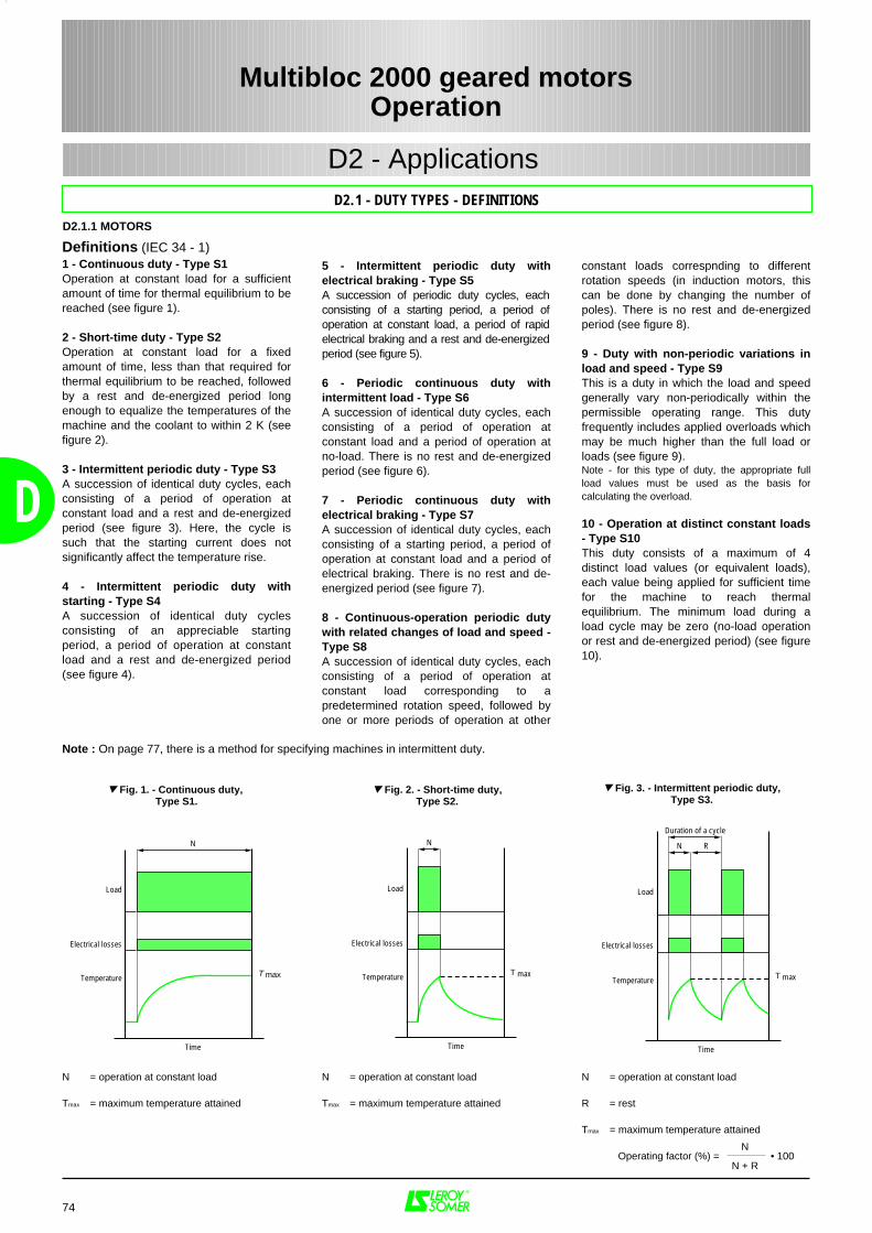
Load
Electrical losses
Temperature
Time
N
T max
R
Duration of a cycle
Load
Electrical losses
Temperature
Time
N
T max
Load
Electrical losses
Temperature
Time
N
T max
74
D
Multibloc 2000 geared motorsOperation
D2.1 - DUTY TYPES - DEFINITIONS
D2 - Applications
D2.1.1 MOTORS
Definitions (IEC 34 - 1)1 - Continuous duty - Type S1Operation at constant load for a sufficientamount of time for thermal equilibrium to bereached (see figure 1).
2 - Short-time duty - Type S2Operation at constant load for a fixedamount of time, less than that required forthermal equilibrium to be reached, followedby a rest and de-energized period longenough to equalize the temperatures of themachine and the coolant to within 2 K (seefigure 2).
3 - Intermittent periodic duty - Type S3A succession of identical duty cycles, eachconsisting of a period of operation atconstant load and a rest and de-energizedperiod (see figure 3). Here, the cycle issuch that the starting current does notsignificantly affect the temperature rise.
4 - Intermittent periodic duty withstarting - Type S4A succession of identical duty cyclesconsisting of an appreciable startingperiod, a period of operation at constantload and a rest and de-energized period(see figure 4).
5 - Intermittent periodic duty withelectrical braking - Type S5 A succession of periodic duty cycles, eachconsisting of a starting period, a period ofoperation at constant load, a period of rapidelectrical braking and a rest and de-energizedperiod (see figure 5).
6 - Periodic continuous duty withintermittent load - Type S6A succession of identical duty cycles, eachconsisting of a period of operation atconstant load and a period of operation atno-load. There is no rest and de-energizedperiod (see figure 6).
7 - Periodic continuous duty withelectrical braking - Type S7A succession of identical duty cycles, eachconsisting of a starting period, a period ofoperation at constant load and a period ofelectrical braking. There is no rest and de-energized period (see figure 7).
8 - Continuous-operation periodic dutywith related changes of load and speed -Type S8A succession of identical duty cycles, eachconsisting of a period of operation atconstant load corresponding to apredetermined rotation speed, followed byone or more periods of operation at other
constant loads correspnding to differentrotation speeds (in induction motors, thiscan be done by changing the number ofpoles). There is no rest and de-energizedperiod (see figure 8).
9 - Duty with non-periodic variations inload and speed - Type S9This is a duty in which the load and speedgenerally vary non-periodically within thepermissible operating range. This dutyfrequently includes applied overloads whichmay be much higher than the full load orloads (see figure 9).Note - for this type of duty, the appropriate fullload values must be used as the basis forcalculating the overload.
10 - Operation at distinct constant loads- Type S10This duty consists of a maximum of 4distinct load values (or equivalent loads),each value being applied for sufficient timefor the machine to reach thermalequilibrium. The minimum load during aload cycle may be zero (no-load operationor rest and de-energized period) (see figure10).
Fig. 1. - Continuous duty, Type S1.
Fig. 2. - Short-time duty, Type S2.
Fig. 3. - Intermittent periodic duty,Type S3.
Note : On page 77, there is a method for specifying machines in intermittent duty.
N = operation at constant load
Tmax = maximum temperature attained
N = operation at constant load
Tmax = maximum temperature attained
N = operation at constant load
R = rest
Tmax = maximum temperature attained
Operating factor (%) = • 100N
N + R
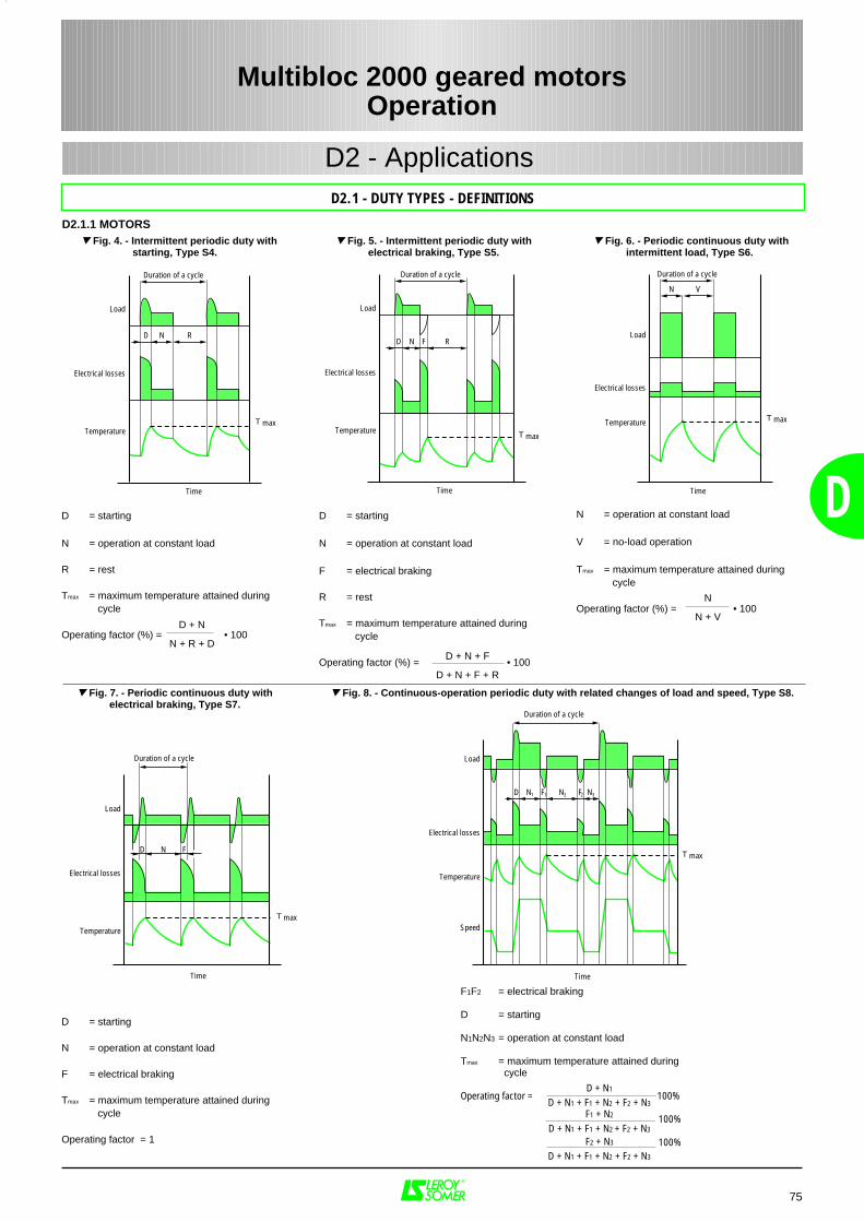
Load
Electrical losses
Temperature
Time
N
T max
F
Duration of a cycle
D
Load
Electrical losses
Temperature
Time
N1
T max
N2
Duration of a cycle
D
Speed
F1 F2 N3
Load
Electrical losses
Temperature
Time
N
T max
R
Duration of a cycle
D F
Load
Electrical losses
Temperature
Time
N
T max
R
Duration of a cycle
D
D = starting
N = operation at constant load
F = electrical braking
R = rest
Tmax = maximum temperature attained during cycle
Operating factor (%) = • 100
D + N1
D + N1 + F1 + N2 + F2 + N3
F1 + N2
D + N1 + F1 + N2 + F2 + N3
F2 + N3
D + N1 + F1 + N2 + F2 + N3
75
Multibloc 2000 geared motorsOperation
D2.1 - DUTY TYPES - DEFINITIONS
D2 - Applications
D2.1.1 MOTORS
D + N + F
D + N + F + R
D = starting
N = operation at constant load
R = rest
Tmax = maximum temperature attained during cycle
Operating factor (%) = • 100
N = operation at constant load
V = no-load operation
Tmax = maximum temperature attained during cycle
Operating factor (%) = • 100
Fig. 4. - Intermittent periodic duty withstarting, Type S4.
Fig. 5. - Intermittent periodic duty with electrical braking, Type S5.
Fig. 6. - Periodic continuous duty withintermittent load, Type S6.
D + N
N + R + D
N
N + V
F1F2 = electrical braking
D = starting
N1N2N3 = operation at constant load
Tmax = maximum temperature attained during cycle
Operating factor = 100%
100%
100%
D = starting
N = operation at constant load
F = electrical braking
Tmax = maximum temperature attained during cycle
Operating factor = 1
Fig. 7. - Periodic continuous duty with electrical braking, Type S7.
Fig. 8. - Continuous-operation periodic duty with related changes of load and speed, Type S8.
Load
Electrical losses
Temperature
Time
N
T max
V
Duration of a cycle
D
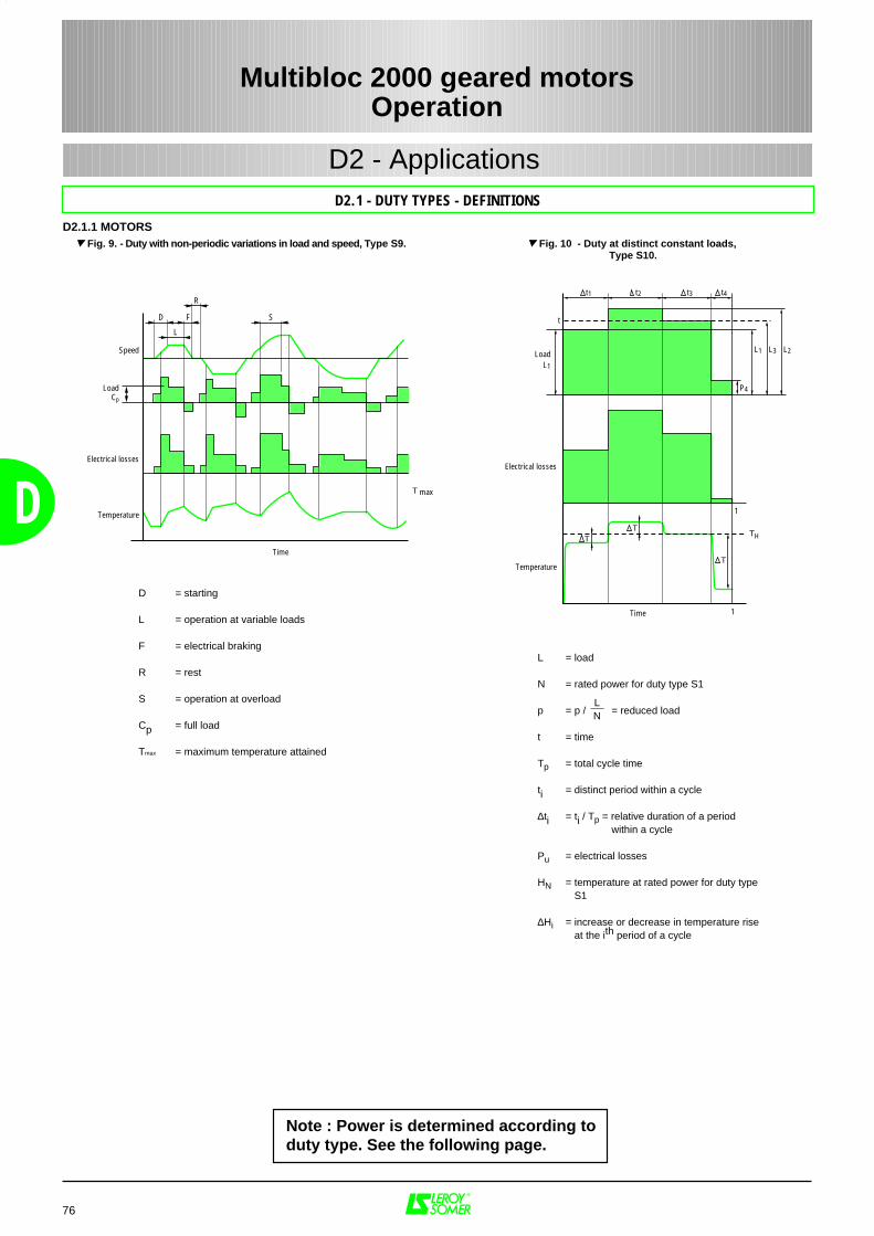
Speed
Electrical losses
Temperature
Time
T max
L
LoadCp
FD
R
S
1
TT
T
TH
Temperature
1
Electrical losses
t1
t
LoadL1
L2L3
t2 t3 t4
P4
Time
L1
76
D
Multibloc 2000 geared motorsOperation
D2.1 - DUTY TYPES - DEFINITIONS
D2 - Applications
D2.1.1 MOTORS
D = starting
L = operation at variable loads F = electrical braking
R = rest
S = operation at overload
Cp = full load
Tmax = maximum temperature attained
Fig. 9. - Duty with non-periodic variations in load and speed, Type S9.
L = load
N = rated power for duty type S1
p = p / = reduced load
t = time
Tp = total cycle time
ti = distinct period within a cycle
∆ti = ti / Tp = relative duration of a period within a cycle
Pu = electrical losses
HN = temperature at rated power for duty type S1
∆Hi = increase or decrease in temperature riseat the ith period of a cycle
LN
Fig. 10 - Duty at distinct constant loads, Type S10.
Note : Power is determined according toduty type. See the following page.
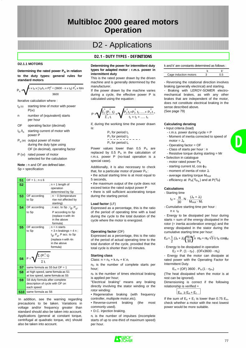
Calculating derating• Input criteria (load)
- r.m.s. power during cycle = P- Moment of inertia corrected to speed of
motor = Je
- Operating factor = OF- Class of starts per hour : n- Resistive torque during starting = Mr
• Selection in catalogue- motor rated power PN
- starting current Id, cos ϕD
- moment of inertia of rotor Jr
- average starting torque Mmot
- efficiency at PN( ) and at P( )
Calculations- Starting time
td = . N .
- Cumulative starting time per hour : n x td
- Energy to be dissipated per hour duringstarts = sum of the energy dissipated in therotor (= inertia acceleration energy) and theenergy dissipated in the stator during thecumulative starting time per hour:
Ed = (Je + Jr) x ntd + ntd √3 U Id cosϕd
- Energy to be dissipated in operationEƒ = P. (1 - ηP) . (OFx3600 - ntd)
- Energy that the motor can dissipate atrated power with the Operating Factor forIntermittent Duty.
Em = (OF) 3600 . PN.(1 - ηPN)
(The heat dissipated when the motor is atrest can be ignored).Dimensioning is correct if the followingrelationship is verified =
Em ≥ Ed + Eƒ
If the sum of Ed + Eƒ is lower than 0.75 Em,check whether a motor with the next lowestpower would be more suitable.
ηPNηP
π30
(Je + Jr)Mmot - Mr
π.N30( )21
2
D
77
Multibloc 2000 geared motorsOperation
D2.1 - DUTY TYPES - DEFINITIONS
D2 - Applications
D2.1.1 MOTORS
P = =
Determining the power for intermittent dutytypes for adapted motor : r.m.s. power inintermittent dutyThis is the rated power drawn by the drivenmachine and is generally determined by themanufacturer.If the power drawn by the machine variesduring a cycle, the effective power P iscalculated using the equation :
Σ1 (Pi . ti) P1.t1+P2. t2 .....+ Pn.t nΣ 1 ti t1 + t2 + ..... tn
if, during the working time the power drawnis:
P1 for period t1P2 for period t2
Pn for period tn
Power values lower than 0.5 PN arereplaced by 0.5 PN in the calculation ofr.m.s. power P (no-load operation is aspecial case).
Additionally, it is also necessary to checkthat, for a particular motor of power PN :• the actual starting time is at most equal to5 seconds,• the maximum output of the cycle does notexceed twice the rated output power P• there is still sufficient accelerating torqueduring the starting period.
Load factor (LF)Expressed as a percentage, this is the ratioof the period of operating time with a loadduring the cycle to the total duration of thecycle where the motor is energized.
Operating factor (OF)Expressed as a percentage, this is the ratioof the period of actual operating time to thetotal duration of the cycle, provided that thetotal cycle is shorter than 10 minutes.
Starting classClass: n = nD + k.nF + k'.ni
nD is the number of complete starts perhour;
nF is the number of times electrical brakingis applied per hour;"Electrical braking" means any brakingdirectly involving the stator winding or therotor winding:• Regenerative braking (with frequencycontroller, multipole motor,etc).• Reverse-current braking (the mostcommonly used).• D.C. injection braking.
ni is the number of impulses (incompletestarts of up to one-third of maximum speed)per hour.
k and k' are constants determined as follows :
- Reversing the rotational direction involvesbraking (generally electrical) and starting.- Braking with LEROY-SOMER electro-mechanical brakes, as with any otherbrakes that are independent of the motor,does not constitute electrical braking in thesense described above.(See page 79)
k k'Cage induction motors 3 0.5
n 2
√2 22
n√
Determining the rated power Pn in relation
to the duty types: general rules forstandard motors
Iterative calculation where :
td (s) starting time of motor with power
P(W)
n number of (equivalent) startsper hour
OF operating factor (decimal)
ID /In starting current of motor withpower P
Pu (W) output power of motorduring the duty type usingOF (in decimal), operating factor
P (W) rated power of motorselected for the calculation
Note : n and OF are defined later.Sp = specification
In addition, see the warning regardingprecautions to be taken. Variations involtage and/or frequency greater thanstandard should also be taken into account.Applications (general at constant torque,centrifugal at quadratic torque, etc) shouldalso be taken into account.
Pn =√n x td x [ ID/In x P]2 + (3600 - n x td) Pu x fdm2
3600
S1 OF = 1 ; n ≤ 6
S2 ; n = 1 length of operation determined by Sp
S3 OF according ; n ~ 0 (temperatureto Sp rise not affected by
starting)
S4 OF according ; n acc. to Sp ; td, Pu,
to Sp P according to Sp (replace n with 4n in the above formula)
S5 OF according ; n = n startsto Sp + 3 n brakings = 4 n ;
td, Pu, P acc. to Sp
(replace n with 4n in the above formula)
S6 P =
S7 same formula as S5 but OF = 1
S8 at high speed, same formula as S1at low speed, same formula as S5
S9 S8 duty formula after complete description of cycle with OF oneach speed
S10 same formula as S6
√Σ (Pi . ti)
Σ ti
2
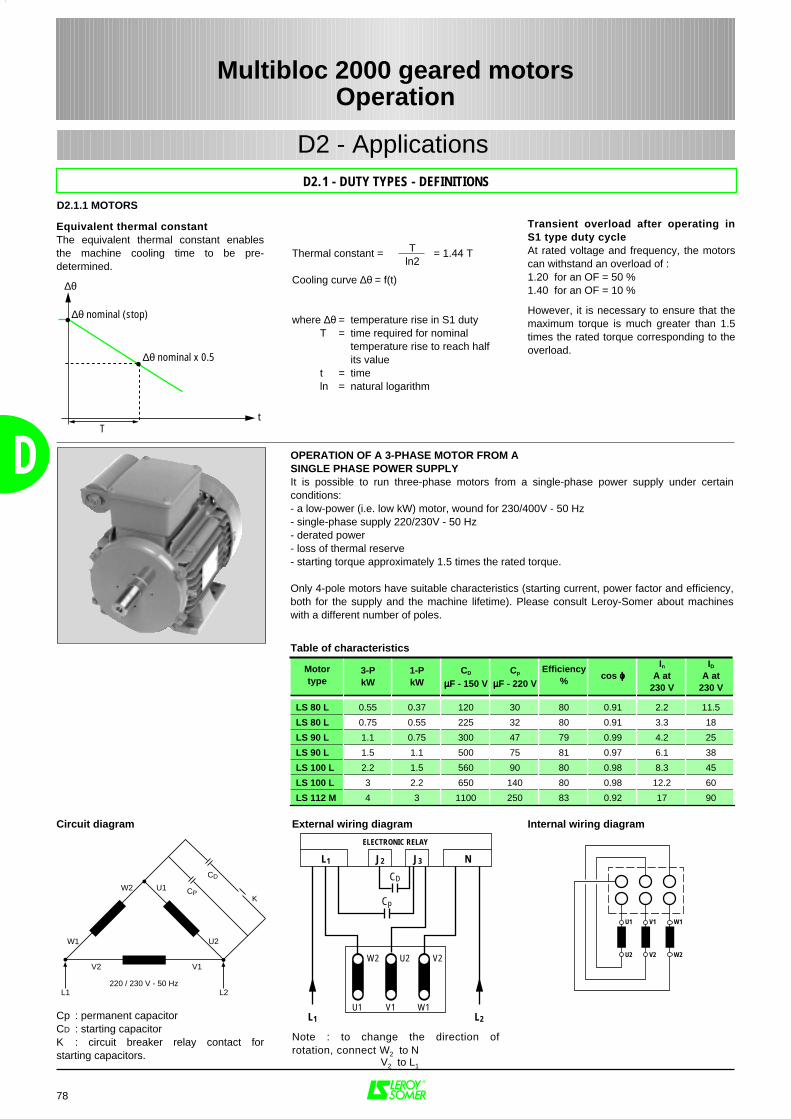
∆θ
∆θ nominal (stop)
∆θ nominal x 0.5
Tt
78
D
Multibloc 2000 geared motorsOperation
D2.1 - DUTY TYPES - DEFINITIONS
D2 - Applications
D2.1.1 MOTORS
Table of characteristics
U1 V1
U2 V2 W2
W1
L1 L2
V2 V1
U2
U1
220 / 230 V - 50 Hz
W1
W2
CD
KCP
Motortype
3-PkW
1-PkW
CD
µµµµF - 150 VCp
µµµµF - 220 V
Efficiency% cos ϕϕϕϕ
In
A at230 V
ID
A at230 V
LS 80 L 0.55 0.37 120 30 80 0.91 2.2 11.5
LS 80 L 0.75 0.55 225 32 80 0.91 3.3 18
LS 90 L 1.1 0.75 300 47 79 0.99 4.2 25
LS 90 L 1.5 1.1 500 75 81 0.97 6.1 38
LS 100 L 2.2 1.5 560 90 80 0.98 8.3 45
LS 100 L 3 2.2 650 140 80 0.98 12.2 60
LS 112 M 4 3 1100 250 83 0.92 17 90
OPERATION OF A 3-PHASE MOTOR FROM A SINGLE PHASE POWER SUPPLYIt is possible to run three-phase motors from a single-phase power supply under certainconditions:- a low-power (i.e. low kW) motor, wound for 230/400V - 50 Hz- single-phase supply 220/230V - 50 Hz- derated power- loss of thermal reserve- starting torque approximately 1.5 times the rated torque.
Only 4-pole motors have suitable characteristics (starting current, power factor and efficiency,both for the supply and the machine lifetime). Please consult Leroy-Somer about machineswith a different number of poles.
Circuit diagram
Cp : permanent capacitorCD : starting capacitorK : circuit breaker relay contact forstarting capacitors.
Internal wiring diagramExternal wiring diagram
Note : to change the direction ofrotation, connect W2 to N V2 to L1
W2 U2 V2
U1 V1 W1
L1 J2 J3 N
ELECTRONIC RELAY
CD
Cp
L1 L2
Equivalent thermal constantThe equivalent thermal constant enablesthe machine cooling time to be pre-determined.
Transient overload after operating inS1 type duty cycleAt rated voltage and frequency, the motorscan withstand an overload of :1.20 for an OF = 50 %1.40 for an OF = 10 %
However, it is necessary to ensure that themaximum torque is much greater than 1.5times the rated torque corresponding to theoverload.
Thermal constant = = 1.44 T
Cooling curve ∆θ = f(t)
where ∆θ = temperature rise in S1 dutyT = time required for nominal
temperature rise to reach half its value
t = timeln = natural logarithm
Tln2
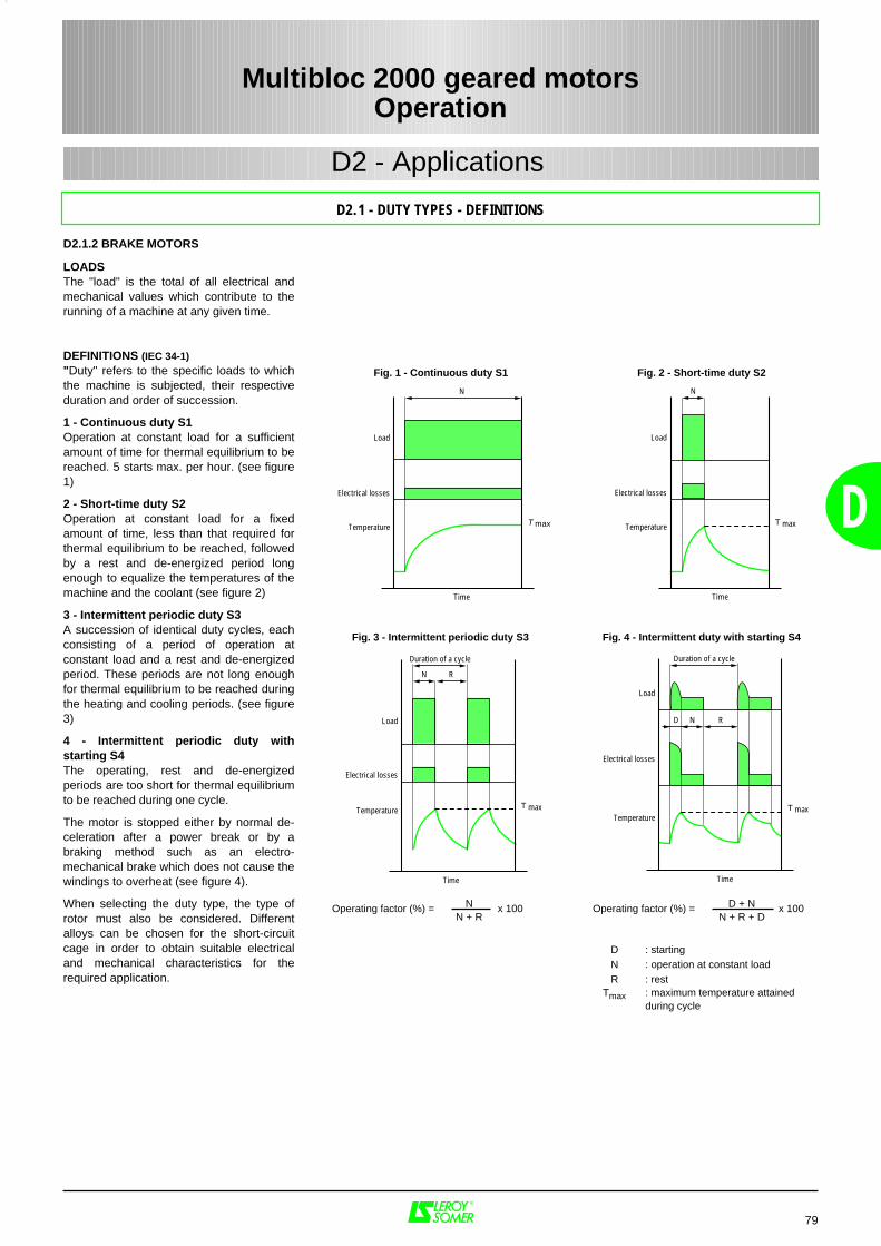
Load
Electrical losses
Temperature
Time
N
T max
R
Duration of a cycle
D
Load
Electrical losses
Temperature
Time
N
T max
79
D
LOADSThe "load" is the total of all electrical andmechanical values which contribute to therunning of a machine at any given time.
DEFINITIONS (IEC 34-1)"Duty" refers to the specific loads to whichthe machine is subjected, their respectiveduration and order of succession.
1 - Continuous duty S1Operation at constant load for a sufficientamount of time for thermal equilibrium to bereached. 5 starts max. per hour. (see figure1)
2 - Short-time duty S2Operation at constant load for a fixedamount of time, less than that required forthermal equilibrium to be reached, followedby a rest and de-energized period longenough to equalize the temperatures of themachine and the coolant (see figure 2)
3 - Intermittent periodic duty S3A succession of identical duty cycles, eachconsisting of a period of operation atconstant load and a rest and de-energizedperiod. These periods are not long enoughfor thermal equilibrium to be reached duringthe heating and cooling periods. (see figure3)
4 - Intermittent periodic duty withstarting S4The operating, rest and de-energizedperiods are too short for thermal equilibriumto be reached during one cycle.
The motor is stopped either by normal de-celeration after a power break or by abraking method such as an electro-mechanical brake which does not cause thewindings to overheat (see figure 4).
When selecting the duty type, the type ofrotor must also be considered. Differentalloys can be chosen for the short-circuitcage in order to obtain suitable electricaland mechanical characteristics for therequired application.
D2.1 - DUTY TYPES - DEFINITIONS
Fig. 1 - Continuous duty S1 Fig. 2 - Short-time duty S2
Fig. 4 - Intermittent duty with starting S4Fig. 3 - Intermittent periodic duty S3
D : startingN : operation at constant loadR : rest
Tmax : maximum temperature attainedduring cycle
Operating factor (%) = x 100NN + R
Operating factor (%) = x 100D + NN + R + D
Multibloc 2000 geared motorsOperation
D2 - Applications
D2.1.2 BRAKE MOTORS
Load
Electrical losses
Temperature
Time
N
T max
Load
Electrical losses
Temperature
Time
N
T max
R
Duration of a cycle
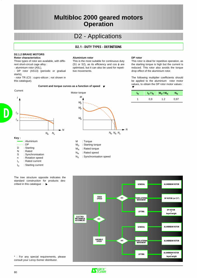
ELECTRO-MECHANICALASSEMBLIES
GENERAL
TRANSLATIONALMOVEMENT
LIFTING
USE
GENERAL
TRANSLATIONALMOVEMENT
LIFTING
ALUMINIUM ROTOR
DP ROTOR (or CS*)
DP ROTOR +
keyed weight
USE
USE
FIXEDSPEED
VARIABLESPEED
ALUMINIUM ROTOR +
keyed weight
ALUMINIUM ROTOR
ALUMINIUM ROTOR
80
D
D2.1 - DUTY TYPES - DEFINITIONS
Multibloc 2000 geared motorsOperation
D2 - Applications
D2.1.2 BRAKE MOTORSRotor characteristicsThree types of rotor are available, with diffe-rent short-circuit cage alloy :- aluminium rotor (A5L),- DP rotor (AS13) (periodic or gradualstarts),- rotor TR (CS : cupro-silicon ; not shown inthis catalogue).
Aluminium rotorThis is the most suitable for continuous duty(S1 or S2), as its efficiency and cos ϕ areoptimised, but it can also be used for repeti-tive movements.
DP rotorThis rotor is ideal for repetitive operation, asthe starting torque is high but the current isreduced. This rotor also avoids the torquedrop effect of the aluminium rotor.
The following multiplier coefficients shouldbe applied to the aluminium rotor motorvalues, to obtain the DP rotor motor values :
IN ID / IN MD / MN NN
1 0,9 1.2 0,97
Current and torque curves as a function of speed
M : Torque MD : Starting torque
MN : Rated torque
NN : Rated speed
NS : Synchronisation speed
The tree structure opposite indicates thestandard construction for products des-cribed in this catalogue :
* : For any special requirements, pleaseconsult your Leroy-Somer distributor.
M
Motor torque
NNN NN
MD
MN
MD
Ns
I
Current
NNN
IN
ID
Ns
Key : : Aluminium - - - - : DP D : Starting N : Rated S : Synchronisation n : Rotation speed In : Rated current
ID : Starting current
81
D
D2.2 - SUPPLY VOLTAGE
Multibloc 2000 geared motorsOperation
D2 - Applications
D2.2.1 REGULATIONS AND STANDARDS
Publication 38
Sixth edition
INTERNATIONAL ELECTROTECHNICAL COMMISSION
IEC STANDARD
230 / 400V
IEC standard voltages
The statement by the electricity consultativecommittee dated 29th May 1986, and the6th edition (1983) of publication No 38 of theInternational Electrotechnical Committee (IEC)have laid down time scales for theharmonisation of standard voltages inEurope.
Within 10 years, voltages at the point ofdelivery will have to be maintained betweenthe following extreme values:
• Single phase current: 207/244V• Three-phase current: 358/423V
The IEC 38 standard gives the Europeanreference voltage as 230/400V three-phase,230V single phase, with a tolerance of +6%to -10% until 2003, and ±10% from then on.
IEC guide 106 also gives tolerances forpower supplies: maximum line drop between customerdelivery point and customer usage point :4% variation in frequency around nominalfrequency :- continuous state: ±1%- transient state: ±2%
Three-phase mains phase-balance error- zero-sequence component and/ornegative phase sequence componentcompared to positive phase sequencecomponent : < 2% Harmonics- relative harmonic content : <10%- individual harmonic voltages : to beestablished Surges and transient power cuts : to beestablished
The motors in this catalogue aredesigned for use on the European powersupply of 230/400V ±10% - 50 Hz.
This means that the same motor canoperate on the following existingsupplies :– 220 / 380 V ±5%– 230 / 400 V ±5% and ±10%– 240 / 415 V ±5%and is therefore suitable for a largenumber of countries worldwide wherefor example it is possible to extend themto some 60 Hz supplies :- 265 / 460 V ±10%.
Regulation relating to change in voltage or supplyShown below are the regulations relating to motors powered by a mains supply : 3-phase 230 / 400 V.
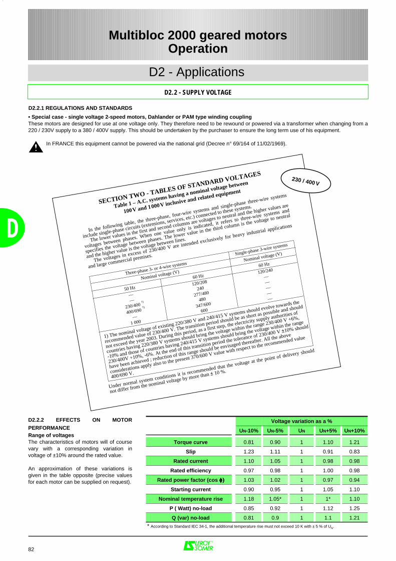
In the following table, the three-phase, four-wire systems and single-phase three-wire systems
include single-phase circuits (extensions, services, etc.) connected to these systems.
The lower values in the first and second columns are voltages to neutral and the higher values are
voltages between phases. When one value only is indicated, it refers to three-wire systems and
specifies the voltage between phases. The lower value in the third column is the voltage to neutral
and the higher value is the voltage between lines.
The voltages in excess of 230/400 V are intended exclusively for heavy industrial applications
and large commercial premises.
SECTION TWO - TABLES OF STANDARD VOLTAGES
Table 1 – A.C. systems having a nominal voltage between
100V and 1000V inclusive and related equipment
Three-phase 3- or 4-wire systems
Nominal voltage (V)
Single-phase 3-wire systems
Nominal voltage (V)
60 Hz
120/240
—————
1) The nominal voltage of existing 220/380 V and 240/415 V systems should evolve towards the
recommended value of 230/400 V. The transition period should be as short as possible and should
not exceed the year 2003. During this period, as a first step, the electricity supply authorities of
countries having 220/380 V systems should bring the voltage within the range 230/400 V +6%,
-10% and those of countries having 240/415 V systems should bring the voltage within the range
230/400V +10%, -6%. At the end of this transition period the tolerance of 230/400 V ±10% should
have been achieved ; reduction of this range should be envisaged thereafter. All the above
considerations apply also to the present 370/600 V value with respect to the recommended value
400/690 V.
230 / 400 V
50 Hz
——
230/400
400/690
—1 000
60 Hz
120/208
240
277/480
480
347/600
600
1)
1)
Under normal system conditions it is recommended that the voltage at the point of delivery should
not differ from the nominal voltage by more than ± 10 %.
82
• Special case - single voltage 2-speed motors, Dahlander or PAM type winding couplingThese motors are designed for use at one voltage only. They therefore need to be rewound or powered via a transformer when changing from a220 / 230V supply to a 380 / 400V supply. This should be undertaken by the purchaser to ensure the long term use of his equipment.
In FRANCE this equipment cannot be powered via the national grid (Decree n° 69/164 of 11/02/1969).
D2.2.2 EFFECTS ON MOTOR
PERFORMANCERange of voltagesThe characteristics of motors will of coursevary with a corresponding variation involtage of ±10% around the rated value.
An approximation of these variations isgiven in the table opposite (precise valuesfor each motor can be supplied on request).
Voltage variation as a %
UN-10% UN-5% UN UN+5% UN+10%
Torque curve 0.81 0.90 1 1.10 1.21
Slip 1.23 1.11 1 0.91 0.83
Rated current 1.10 1.05 1 0.98 0.98
Rated efficiency 0.97 0.98 1 1.00 0.98
Rated power factor (cos ϕϕϕϕ)))) 1.03 1.02 1 0.97 0.94
Starting current 0.90 0.95 1 1.05 1.10
Nominal temperature rise 1.18 1.05* 1 1* 1.10
P ( Watt) no-load 0.85 0.92 1 1.12 1.25
Q (var) no-load 0.81 0.9 1 1.1 1.21
* According to Standard IEC 34-1, the additional temperature rise must not exceed 10 K with ± 5 % of UN.
D
D2 - Applications
D2.2 - SUPPLY VOLTAGE
Multibloc 2000 geared motorsOperation
D2.2.1 REGULATIONS AND STANDARDS
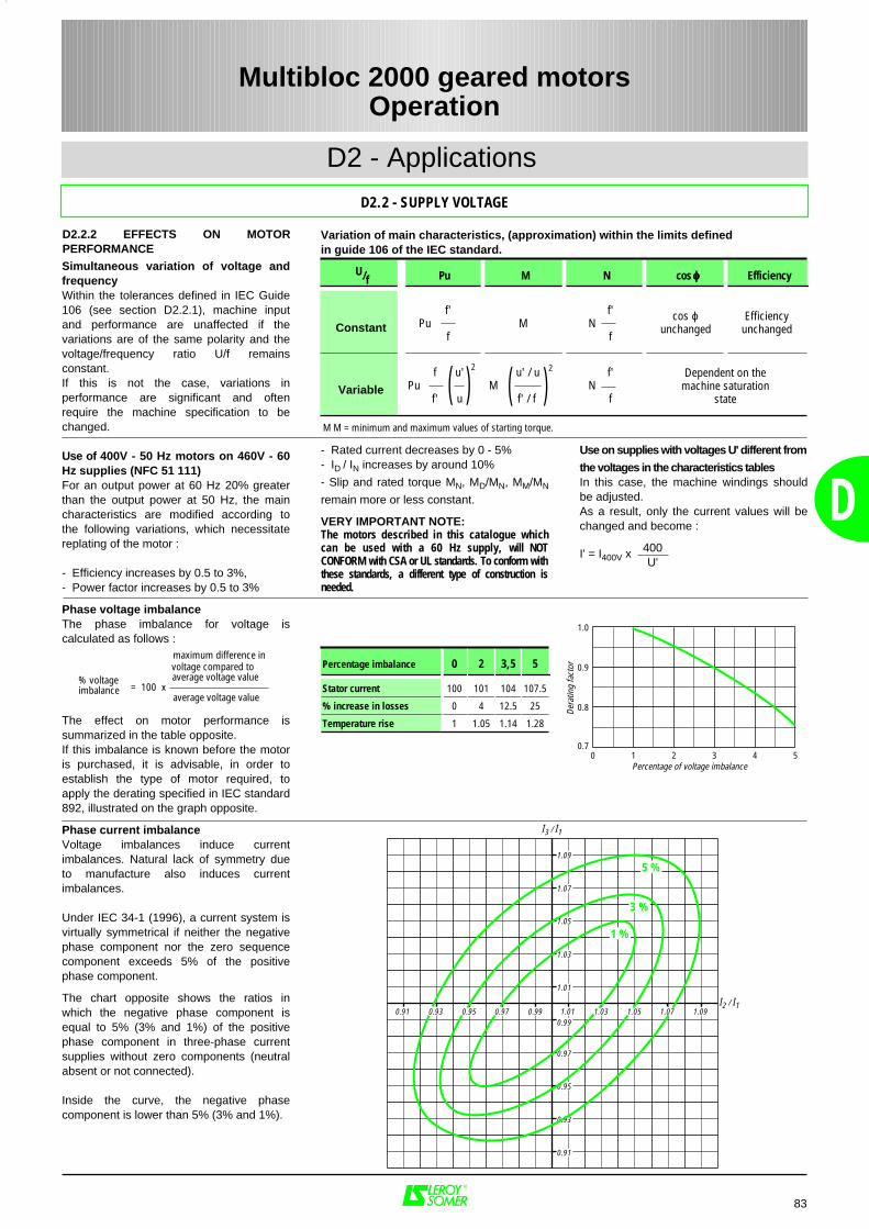
0 1 2 3 4 5
0.8
0.9
1.0
0.7
Percentage of voltage imbalance
Dera
ting
fact
or
0.91
0.93
0.95
0.97
0.99
1.01
1.03
1.05
1.07
1.09
0.990.970.950.930.91 1.091.071.051.031.01I2 / I1
I3 / I1
5 %
3 %
1 %
83
D
D2 - Applications
D2.2 - SUPPLY VOLTAGE
Multibloc 2000 geared motorsOperation
D2.2.2 EFFECTS ON MOTORPERFORMANCESimultaneous variation of voltage andfrequencyWithin the tolerances defined in IEC Guide106 (see section D2.2.1), machine inputand performance are unaffected if thevariations are of the same polarity and thevoltage/frequency ratio U/f remainsconstant.If this is not the case, variations inperformance are significant and oftenrequire the machine specification to bechanged.
Use of 400V - 50 Hz motors on 460V - 60Hz supplies (NFC 51 111)For an output power at 60 Hz 20% greaterthan the output power at 50 Hz, the maincharacteristics are modified according tothe following variations, which necessitatereplating of the motor :
- Efficiency increases by 0.5 to 3%,- Power factor increases by 0.5 to 3%
Phase voltage imbalanceThe phase imbalance for voltage iscalculated as follows :
maximum difference in voltage compared to average voltage value = 100 x
average voltage value
The effect on motor performance issummarized in the table opposite.If this imbalance is known before the motoris purchased, it is advisable, in order toestablish the type of motor required, toapply the derating specified in IEC standard892, illustrated on the graph opposite.
Phase current imbalanceVoltage imbalances induce currentimbalances. Natural lack of symmetry dueto manufacture also induces currentimbalances.
Under IEC 34-1 (1996), a current system isvirtually symmetrical if neither the negativephase component nor the zero sequencecomponent exceeds 5% of the positivephase component.
The chart opposite shows the ratios inwhich the negative phase component isequal to 5% (3% and 1%) of the positivephase component in three-phase currentsupplies without zero components (neutralabsent or not connected).
Inside the curve, the negative phasecomponent is lower than 5% (3% and 1%).
- Rated current decreases by 0 - 5%- ID / IN increases by around 10%
- Slip and rated torque MN, MD/MN, MM/MN
remain more or less constant.
VERY IMPORTANT NOTE:The motors described in this catalogue whichcan be used with a 60 Hz supply, will NOTCONFORM with CSA or UL standards. To conform withthese standards, a different type of construction isneeded.
Use on supplies with voltages U' different from
the voltages in the characteristics tablesIn this case, the machine windings shouldbe adjusted.As a result, only the current values will bechanged and become :
I' = I400V x
U/f Pu M N cos ϕϕϕϕ Efficiency
Constant
f' Pu
fM
f' N
f
cos ϕunchanged
Efficiencyunchanged
Variable
f u' Pu
f' u
u' / u M
f' / f
f' N
f
M M = minimum and maximum values of starting torque.
( )2
( )2 Dependent on the
machine saturationstate
Variation of main characteristics, (approximation) within the limits definedin guide 106 of the IEC standard.
Percentage imbalance 0 2 3,5 5
Stator current 100 101 104 107.5
% increase in losses 0 4 12.5 25
Temperature rise 1 1.05 1.14 1.28
% voltageimbalance
400U'
84
Insulation class
The machines in the LS series have beendesigned with a Class F insulation systemfor the windings.
Class F allows for temperature rises of 105 K(measured by the resistance variationmethod) and maximum temperatures of155°C at the hot spots in the machine (cfIEC 85 and IEC 34-1).Complete impregnation with tropicalizedvarnish of thermal class 180°C givesprotection against attacks from theenvironment, such as 90% relativehumidity, interference, etc.For special constructions, (see table in the"Environment" section) the winding is ofclass H and impregnated with specialvarnishes which enable it to operate inconditions of high temperatures with relativeair humidity of up to 100%.
Temperature rise (∆T*) and maximumtemperatures at hot spots (Tmax) for insu-lation classes (IEC 34 - 1).
* Measured using the winding resistance variationmethod.
The insulation of the windings is monitoredin two ways :
a - Dielectric inspection which involveschecking the leakage current, at an appliedvoltage of (2U + 1000) V, in conditionscomplying with the IEC 34-1 standard(systematic test).
b - Monitoring the insulation resistancebetween the coils and between the coilsand the earth (sampling test) at a D.C.voltage of 500V or 1000V.
∆T* Tmax
Class B 80 K 125°CClass F 105 K 155°C
Class H 125 K 180°C
Temperature rise and thermal reserve
LEROY-SOMER motors are built to have amaximum winding temperature rise of 80 Kunder normal operating conditions (ambienttemperature 40°C, altitude below 1000 m,rated voltage and frequency, rated load).Running at the voltage limits (± 10% of UN)will induce overheating of less than 15 K.
In IEC 34-1 and 34-2, the temperature rise(∆T) is calculated according to the windingresistance variation method using theformula:
∆T = (235 + T1) + (T1 - T2)
R1 : cold resistance measured at
ambient temperature T1
R2 : stabilized hot resistance measured
at ambient temperature T2
235 : coefficient for a copper winding (foran aluminium winding, thecoefficient is 225).
The result is a thermal reserve linkedto the following factors :• a difference of 25 K between the
nominal temperature rise (Un, fn, Pn)and the permissible temperature rise(105 K) for class F insulation.
• a difference of over 20 K at thevoltage limits (Un ± 10%) betweenthe actual temperature rise and thepermissible temperature rise.
R2 - R1
R1D
D2 - Applications
D2.3 - INSULATION CLASS - TEMPERATURE RISE AND THERMAL RESERVE
Multibloc 2000 geared motorsOperation
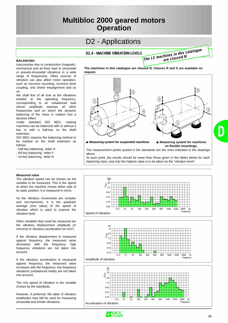
0.10
0.25
0.63
1.6
4.0
10
12.5 25 50 100 200 400 800 1600 3200 6400 HzFrequency
ms2
A rm
s
0.10
0.25
0.63
1.6
4.0
10µm
12.5 25 50 100 200 400 800 1600 3200 6400 HzFrequency
S rm
s
0.04
0.10
0.25
0.63
1.6
40
mms
12.5 25 50 100 200 400 800 1600 3200 6400 HzFrequency
V rm
s
85
D
D2 - Applications
D2.4 - MACHINE VIBRATION LEVELS
Multibloc 2000 geared motorsOperation
BALANCINGInaccuracies due to construction (magnetic,mechanical and air-flow) lead to sinusoidalor pseudo-sinusoidal vibrations in a widerange of frequencies. Other sources ofvibration can also affect motor operation,such as incorrect mounting, incorrect drivecoupling, end shield misalignment and soon.We shall first of all look at the vibrationsemitted at the operating frequency,corresponding to an unbalanced loadwhose amplitude swamps all otherfrequencies and on which the dynamicbalancing of the mass in rotation has adecisive effect.Under standard ISO 8821, rotatingmachines can be balanced with or without akey or with a half-key on the shaftextension.ISO 8821 requires the balancing method tobe marked on the shaft extension asfollows:- half-key balancing : letter H- full key balancing : letter F- no-key balancing : letter N
The measurement points quoted in the standards are the ones indicated in the drawingsabove.At each point, the results should be lower than those given in the tables below for eachbalancing class, and only the highest value is to be taken as the "vibration level".
Measuring system for suspended machines Measuring system for machineson flexible mountings.
1
4
5
2
3
Speed of vibration
Acceleration of vibration
Amplitude of vibration
Measured valueThe vibration speed can be chosen as thevariable to be measured. This is the speedat which the machine moves either side ofits static position. It is measured in mm/s.
As the vibratory movements are complexand non-harmonic, it is the quadraticaverage (rms value) of the speed ofvibration which is used to express thevibration level.
Other variables that could be measured arethe vibratory displacement amplitude (inmicrons) or vibratory acceleration (in m/s2).
If the vibratory displacement is measuredagainst frequency, the measured valuedecreases with the frequency: highfrequency vibrations are not taken intoaccount.
If the vibratory acceleration is measuredagainst frequency, the measured valueincreases with the frequency: low frequencyvibrations (unbalanced loads) are not takeninto account.
The rms speed of vibration is the variablechosen by the standards.
However, if preferred, the table of vibrationamplitudes may still be used for measuringsinusoidal and similar vibrations.
The machines in this catalogue are classed N. Classes R and S are available on request.
1
4
5
2
3
The LS machines in this catalogue
are classed N
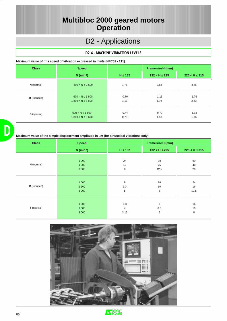
86
D
D2 - Applications
D2.4 - MACHINE VIBRATION LEVELS
Multibloc 2000 geared motorsOperation
Class Speed Frame size H (mm)
N (min-1) H ≤ 132 132 < H ≤ 225 225 < H ≤ 315
N (normal) 600 < N ≤ 3 600 1.76 2.83 4.45
R (reduced)
600 < N ≤ 1 800
1 800 < N ≤ 3 600
0.70
1.13
1.13
1.76
1.76
2.83
S (special) 600 < N ≤ 1 800
1 800 < N ≤ 3 600
0.44
0.70
0.70
1.13
1.13
1.76
Maximum value of rms speed of vibration expressed in mm/s (NFC51 - 111)
Class Speed Frame size H (mm)
N (min-1) H ≤ 132 132 < H ≤ 225 225 < H ≤ 315
N (normal)1 000
1 500
3 000
24
16
8
38
25
12.5
60
40
20
R (reduced)1 000
1 500
3 000
9
6.3
5
16
10
8
24
16
12.5
S (special)1 000
1 500
3 000
6.3
4
3.15
9
6.3
5
16
10
8
Maximum value of the simple displacement amplitude in µm (for sinusoidal vibrations only)
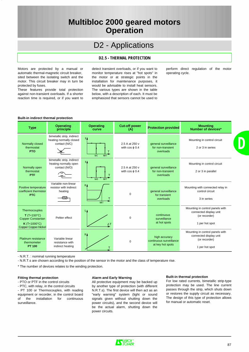
87
D
D2 - Applications
D2.5 - THERMAL PROTECTION
Multibloc 2000 geared motorsOperation
Built-in indirect thermal protection
Motors are protected by a manual orautomatic thermal-magnetic circuit breaker,sited between the isolating switch and themotor. This circuit breaker may in turn beprotected by fuses.These features provide total protectionagainst non-transient overloads. If a shorterreaction time is required, or if you want to
perform direct regulation of the motoroperating cycle.
detect transient overloads, or if you want tomonitor temperature rises at "hot spots" inthe motor or at strategic points in theinstallation for maintenance purposes, itwould be advisable to install heat sensors.The various types are shown in the tablebelow, with a description of each. It must beemphasized that sensors cannot be used to
Type Operating principle
Operating curve
Cut-off power (A) Protection provided Mounting
Number of devices*
Normally closedthermostat
PTO
bimetallic strip, indirectheating normally closed
contact (N/C) 2.5 A at 250 vwith cos ϕ 0.4
general surveillancefor non-transient
overloads
Mounting in control circuit
2 or 3 in series
Normally openthermostat
PTF
bimetallic strip, indirectheating normally open
contact (N/O) 2.5 A at 250 vwith cos ϕ 0.4
general surveillancefor non-transient
overloads
Mounting in control circuit
2 or 3 in parallel
Positive temperaturecoefficient thermistor
PTC
Variable non-linear resistor with indirect
heating0
general surveillancefor transient
overloads
Mounting with connected relay incontrol circuit
3 in series
Thermocouples
T (T<150°C)Copper Constantan
K (T<1000°C)Copper Copper-Nickel
Peltier effect 0continuous surveillanceat hot spots
Mounting in control panels withconnected display unit
(or recorder)
1 per hot spot
Platinum resistancethermometer
PT 100
Variable linear resistance withindirect heating
0
high accuracycontinuous surveillance
at key hot spots
Mounting in control panels withconnected display unit
(or recorder)
1 per hot spot
- N.R.T. : nominal running temperature- N.R.T.s are chosen according to the position of the sensor in the motor and the class of temperature rise.
* The number of devices relates to the winding protection.
Built-in thermal protectionFor low rated currents, bimetallic strip-typeprotection may be used. The line currentpasses through the strip, which shuts downor restores the supply circuit as necessary.The design of this type of protection allowsfor manual or automatic reset.
Fitting thermal protection- PTO or PTF in the control circuits- PTC, with relay, in the control circuits- PT 100 or Thermocouples, with readingequipment or recorder, in the control boardof the installation for continuoussurveillance.
Alarm and Early WarningAll protective equipment may be backed upby another type of protection (with differentN.R.T.s). The first device will then act as an"early warning" system (light or soundsignals given without shutting down thepower circuits), and the second device willbe the actual alarm, shutting down thepower circuits.
I
N/C NRT
T
I
N/O NRT
T
R
NRT
T
S
T
R
T
88
Multibloc 2000 geared motorsCharacteristics
Machining
3-dimensional inspection
E
E1 - Selection of gearbox with "AP" input shaft 90
E1.1 - Method ............................................................................................................... 90
E1.2 - Example and "AP" gearbox description .............................................................. 91
E1.3 - Selection tables .................................................................................................. 92
E1.3.1 - Input speed 2850 min-1 .................................................................... 92
E1.3.2 - Input speed 1430 min-1 .................................................................... 93
E1.3.3 - Input speed 950 min-1 .................................................................... 94
E1.3.4 - Input speed 715 min-1 .................................................................... 95
E2 - Selection of geared motors 96
E2.1 - Method ............................................................................................................... 96
E2.2 - Example and geared motor description ............................................................. 97
E2.3 - Quick selection using AGMA ............................................................................. 98
• AGMA I ............................................................................................ 98
• AGMA II ........................................................................................... 99
• AGMA III .......................................................................................... 100
E2.4 - Tables of mechanical characteristics .................................................................. 101
• 4 poles, 8 poles and 4/8 poles ......................................................... 101 to 128
• 2/8 poles .......................................................................................... 130 to 137
E2.5 - Tables of electrical characteristics ...................................................................... 138
• 1 fixed speed no brake .....................................................................138 to 145
• 2 fixed speeds no brake .................................................................. 146
• 1 fixed speed FCR brake ................................................................. 147 to 150
• 1 fixed speed FCO brake .................................................................151 to 152
• 1 fixed speed FAST brake ............................................................... 153 to 155
• 1 fixed speed FAP2-FAP brake ....................................................... 156 to 159
• 2 fixed speeds with brakes ..............................................................160 to 162
• 1 variable speed no brake ................................................................ 163
• 1 variable speed with brakes ........................................................... 164
89
E
PAGES
Multibloc 2000 geared motorsCharacteristics
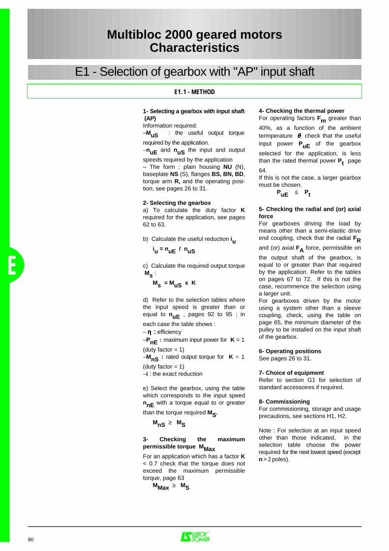
E
4- Checking the thermal power For operating factors Fm greater than
40%, as a function of the ambienttermperature θθθθ check that the usefulinput power PuE of the gearbox
selected for the application, is lessthan the rated thermal power Pt page
64.If this is not the case, a larger gearboxmust be chosen.
PuE ≤ Pt
5- Checking the radial and (or) axialforceFor gearboxes driving the load bymeans other than a semi-elastic driveend coupling, check that the radial FRand (or) axial FA force, permissible on
the output shaft of the gearbox, isequal to or greater than that requiredby the application. Refer to the tableson pages 67 to 72. If this is not thecase, recommence the selection usinga larger unit.For gearboxes driven by the motorusing a system other than a sleevecoupling, check, using the table onpage 65, the minimum diameter of thepulley to be installed on the input shaftof the gearbox.
6- Operating positionsSee pages 26 to 31.
7- Choice of equipmentRefer to section G1 for selection ofstandard accessoires if required.
8- Commissioning For commissioning, storage and usageprecautions, see sections H1, H2.
Note : For selection at an input speedother than those indicated, in theselection table choose the powerrequired for the next lowest speed (exceptn > 2 poles).
1- Selecting a gearbox with input shaft (AP)Information required:–MuS : the useful output torque
required by the application.–nuE and nuS the input and output
speeds required by the application– The form : plain housing NU (N),baseplate NS (S), flanges BS, BN, BD,torque arm R, and the operating posi-tion, see pages 26 to 31.
2- Selecting the gearboxa) To calculate the duty factor Krequired for the application, see pages62 to 63.
b) Calculate the useful reduction iuiu = nuE / nuS
c) Calculate the required output torque Ms :
Ms = MuS x K
d) Refer to the selection tables wherethe input speed is greater than orequal to nuE , pages 92 to 95 ; in
each case the table shows : – ηηηη :::: efficiency–PnE : maximum input power for K = 1
(duty factor = 1)–MnS : rated output torque for K = 1
(duty factor = 1)–i : the exact reduction
e) Select the gearbox, using the tablewhich corresponds to the input speednnE with a torque equal to or greater
than the torque required MS.
MnS ≥ MS
3- Checking the maximumpermissible torque MMaxFor an application which has a factor K< 0.7 check that the torque does notexceed the maximum permissibletorque, page 63
MMax ≥ MS
90
Multibloc 2000 geared motorsCharacteristics
E1 - Selection of gearbox with "AP" input shaft
E1.1 - METHOD
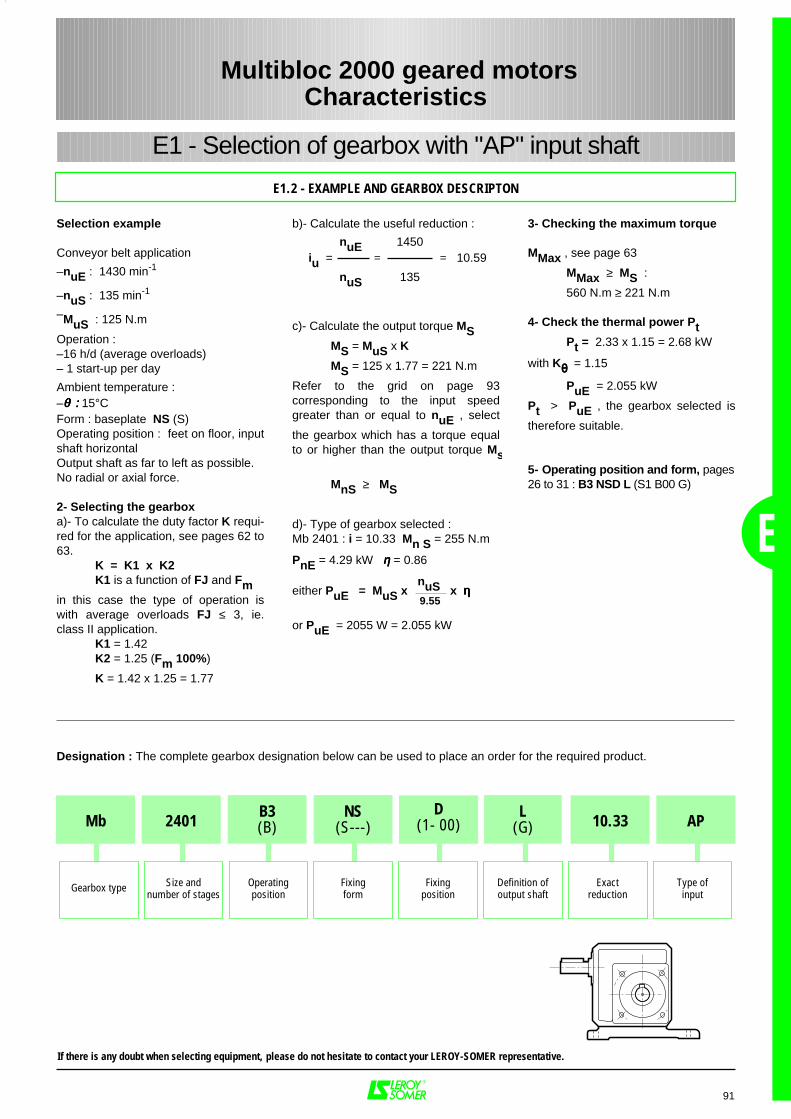
E
91
E1.2 - EXAMPLE AND GEARBOX DESCRIPTON
Multibloc 2000 geared motorsCharacteristics
E1 - Selection of gearbox with "AP" input shaft
Selection example
Conveyor belt application
–nuE : 1430 min-1
–nuS : 135 min-1
–MuS : 125 N.m
Operation : –16 h/d (average overloads)– 1 start-up per day
Ambient temperature :–θθθθ :::: 15°CForm : baseplate NS (S)Operating position : feet on floor, inputshaft horizontalOutput shaft as far to left as possible.No radial or axial force.
2- Selecting the gearboxa)- To calculate the duty factor K requi-red for the application, see pages 62 to63.
K = K1 x K2K1 is a function of FJ and Fm
in this case the type of operation iswith average overloads FJ ≤ 3, ie.class II application.
K1 = 1.42 K2 = 1.25 (Fm 100%)
K = 1.42 x 1.25 = 1.77
3- Checking the maximum torque
MMax , see page 63
MMax ≥ MS :
560 N.m ≥ 221 N.m
4- Check the thermal power PtPt = 2.33 x 1.15 = 2.68 kW
with Kθθθθ = 1.15
PuE = 2.055 kW
Pt > PuE , the gearbox selected is
therefore suitable.
5- Operating position and form, pages26 to 31 : B3 NSD L (S1 B00 G)
b)- Calculate the useful reduction :
c)- Calculate the output torque MSMS = MuS x K
MS = 125 x 1.77 = 221 N.m
Refer to the grid on page 93corresponding to the input speedgreater than or equal to nuE , select
the gearbox which has a torque equalto or higher than the output torque Ms
MnS ≥ MS
d)- Type of gearbox selected : Mb 2401 : i = 10.33 Mn S = 255 N.m
PnE = 4.29 kW ηηηη = 0.86
either PuE = MuS x nuS x ηηηη
or PuE = 2055 W = 2.055 kW
nuE 1450iu = = = 10.59
nuS 135
9.55
Designation : The complete gearbox designation below can be used to place an order for the required product.
If there is any doubt when selecting equipment, please do not hesitate to contact your LEROY-SOMER representative.
Mb AP2401D
(1- 00) 10.33
Gearbox type Type ofinput
Size andnumber of stages
Operatingposition
Fixingform
Fixingposition
Definition ofoutput shaft
Exactreduction
B3(B)
NS(S---)
L(G)
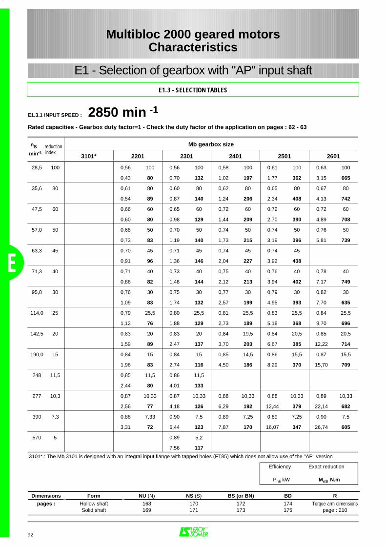
E
92
E1.3.1 INPUT SPEED : 2850 min -1
28,5 100 0,56 100 0,56 100 0,58 100 0,61 100 0,63 100
0,43 80 0,70 132 1,02 197 1,77 362 3,15 665
35,6 80 0,61 80 0,60 80 0,62 80 0,65 80 0,67 80
0,54 89 0,87 140 1,24 206 2,34 408 4,13 742
47,5 60 0,66 60 0,65 60 0,72 60 0,72 60 0,72 60
0,60 80 0,98 129 1,44 209 2,70 390 4,89 708
57,0 50 0,68 50 0,70 50 0,74 50 0,74 50 0,76 50
0,73 83 1,19 140 1,73 215 3,19 396 5,81 739
63,3 45 0,70 45 0,71 45 0,74 45 0,74 45
0,91 96 1,36 146 2,04 227 3,92 438
71,3 40 0,71 40 0,73 40 0,75 40 0,76 40 0,78 40
0,86 82 1,48 144 2,12 213 3,94 402 7,17 749
95,0 30 0,76 30 0,75 30 0,77 30 0,79 30 0,82 30
1,09 83 1,74 132 2,57 199 4,95 393 7,70 635
114,0 25 0,79 25,5 0,80 25,5 0,81 25,5 0,83 25,5 0,84 25,5
1,12 76 1,88 129 2,73 189 5,18 368 9,70 696
142,5 20 0,83 20 0,83 20 0,84 19,5 0,84 20,5 0,85 20,5
1,59 89 2,47 137 3,70 203 6,67 385 12,22 714
190,0 15 0,84 15 0,84 15 0,85 14,5 0,86 15,5 0,87 15,5
1,96 83 2,74 116 4,50 186 8,29 370 15,70 709
248 11,5 0,85 11,5 0,86 11,5
2,44 80 4,01 133
277 10,3 0,87 10,33 0,87 10,33 0,88 10,33 0,88 10,33 0,89 10,33
2,56 77 4,18 126 6,29 192 12,44 379 22,14 682
390 7,3 0,88 7,33 0,90 7,5 0,89 7,25 0,89 7,25 0,90 7,5
3,31 72 5,44 123 7,87 170 16,07 347 26,74 605
570 5 0,89 5,2
7,56 117
3101* : The Mb 3101 is designed with an integral input flange with tapped holes (FT85) which does not allow use of the "AP" version
nS reduction Mb gearbox size
min-1
index3101* 2201 2301 2401 2501 2601
Efficiency Exact reduction
PnE kW MnS N.m
Dimensions Form NU (N) NS (S) BS (or BN) BD R
pages : Hollow shaft 168 170 172 174 Torque arm dimensionsSolid shaft 169 171 173 175 page : 210
Rated capacities - Gearbox duty factor=1 - Check the duty factor of the application on pages : 62 - 63
Multibloc 2000 geared motorsCharacteristics
E1.3 - SELECTION TABLES
E1 - Selection of gearbox with "AP" input shaft
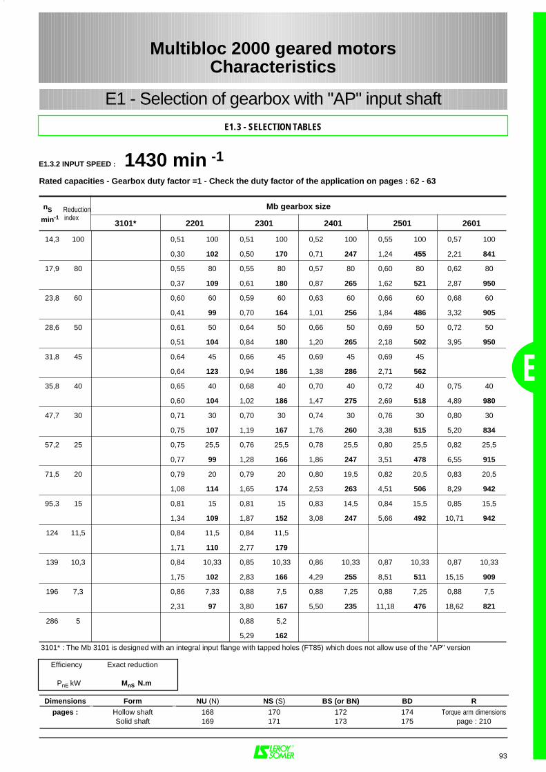
E
93
14,3 100 0,51 100 0,51 100 0,52 100 0,55 100 0,57 100
0,30 102 0,50 170 0,71 247 1,24 455 2,21 841
17,9 80 0,55 80 0,55 80 0,57 80 0,60 80 0,62 80
0,37 109 0,61 180 0,87 265 1,62 521 2,87 950
23,8 60 0,60 60 0,59 60 0,63 60 0,66 60 0,68 60
0,41 99 0,70 164 1,01 256 1,84 486 3,32 905
28,6 50 0,61 50 0,64 50 0,66 50 0,69 50 0,72 50
0,51 104 0,84 180 1,20 265 2,18 502 3,95 950
31,8 45 0,64 45 0,66 45 0,69 45 0,69 45
0,64 123 0,94 186 1,38 286 2,71 562
35,8 40 0,65 40 0,68 40 0,70 40 0,72 40 0,75 40
0,60 104 1,02 186 1,47 275 2,69 518 4,89 980
47,7 30 0,71 30 0,70 30 0,74 30 0,76 30 0,80 30
0,75 107 1,19 167 1,76 260 3,38 515 5,20 834
57,2 25 0,75 25,5 0,76 25,5 0,78 25,5 0,80 25,5 0,82 25,5
0,77 99 1,28 166 1,86 247 3,51 478 6,55 915
71,5 20 0,79 20 0,79 20 0,80 19,5 0,82 20,5 0,83 20,5
1,08 114 1,65 174 2,53 263 4,51 506 8,29 942
95,3 15 0,81 15 0,81 15 0,83 14,5 0,84 15,5 0,85 15,5
1,34 109 1,87 152 3,08 247 5,66 492 10,71 942
124 11,5 0,84 11,5 0,84 11,5
1,71 110 2,77 179
139 10,3 0,84 10,33 0,85 10,33 0,86 10,33 0,87 10,33 0,87 10,33
1,75 102 2,83 166 4,29 255 8,51 511 15,15 909
196 7,3 0,86 7,33 0,88 7,5 0,88 7,25 0,88 7,25 0,88 7,5
2,31 97 3,80 167 5,50 235 11,18 476 18,62 821
286 5 0,88 5,2
5,29 162
3101* : The Mb 3101 is designed with an integral input flange with tapped holes (FT85) which does not allow use of the "AP" version
nS Reduction Mb gearbox size
min-1
index3101* 2201 2301 2401 2501 2601
Dimensions Form NU (N) NS (S) BS (or BN) BD R
pages : Hollow shaft 168 170 172 174 Torque arm dimensionsSolid shaft 169 171 173 175 page : 210
Efficiency Exact reduction
PnE kW MnS N.m
E1.3.2 INPUT SPEED : 1430 min -1Rated capacities - Gearbox duty factor =1 - Check the duty factor of the application on pages : 62 - 63
Multibloc 2000 geared motorsCharacteristics
E1.3 - SELECTION TABLES
E1 - Selection of gearbox with "AP" input shaft
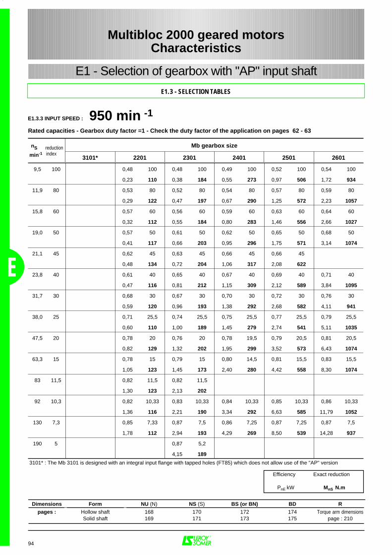
E
94
9,5 100 0,48 100 0,48 100 0,49 100 0,52 100 0,54 100
0,23 110 0,38 184 0,55 273 0,97 506 1,72 934
11,9 80 0,53 80 0,52 80 0,54 80 0,57 80 0,59 80
0,29 122 0,47 197 0,67 290 1,25 572 2,23 1057
15,8 60 0,57 60 0,56 60 0,59 60 0,63 60 0,64 60
0,32 112 0,55 184 0,80 283 1,46 556 2,66 1027
19,0 50 0,57 50 0,61 50 0,62 50 0,65 50 0,68 50
0,41 117 0,66 203 0,95 296 1,75 571 3,14 1074
21,1 45 0,62 45 0,63 45 0,66 45 0,66 45
0,48 134 0,72 204 1,06 317 2,08 622
23,8 40 0,61 40 0,65 40 0,67 40 0,69 40 0,71 40
0,47 116 0,81 212 1,15 309 2,12 589 3,84 1095
31,7 30 0,68 30 0,67 30 0,70 30 0,72 30 0,76 30
0,59 120 0,96 193 1,38 292 2,68 582 4,11 941
38,0 25 0,71 25,5 0,74 25,5 0,75 25,5 0,77 25,5 0,79 25,5
0,60 110 1,00 189 1,45 279 2,74 541 5,11 1035
47,5 20 0,78 20 0,76 20 0,78 19,5 0,79 20,5 0,81 20,5
0,82 129 1,32 202 1,95 299 3,52 573 6,43 1074
63,3 15 0,78 15 0,79 15 0,80 14,5 0,81 15,5 0,83 15,5
1,05 123 1,45 173 2,40 280 4,42 558 8,30 1074
83 11,5 0,82 11,5 0,82 11,5
1,30 123 2,13 202
92 10,3 0,82 10,33 0,83 10,33 0,84 10,33 0,85 10,33 0,86 10,33
1,36 116 2,21 190 3,34 292 6,63 585 11,79 1052
130 7,3 0,85 7,33 0,87 7,5 0,86 7,25 0,87 7,25 0,87 7,5
1,78 112 2,94 193 4,29 269 8,50 539 14,28 937
190 5 0,87 5,2
4,15 189
3101* : The Mb 3101 is designed with an integral input flange with tapped holes (FT85) which does not allow use of the "AP" version
nS reduction Mb gearbox size
min-1
index3101* 2201 2301 2401 2501 2601
Dimensions Form NU (N) NS (S) BS (or BN) BD R
pages : Hollow shaft 168 170 172 174 Torque arm dimensionsSolid shaft 169 171 173 175 page : 210
Efficiency Exact reduction
PnE kW MnS N.m
E1.3.3 INPUT SPEED : 950 min -1Rated capacities - Gearbox duty factor =1 - Check the duty factor of the application on pages 62 - 63
Multibloc 2000 geared motorsCharacteristics
E1 - Selection of gearbox with "AP" input shaft
E1.3 - SELECTION TABLES

E
95
28,5 100 0,45 100 0,45 100 0,47 100 0,49 100 0,51 100
0,20 120 0,33 197 0,47 296 0,83 543 1,47 1004
8,9 80 0,50 80 0,49 80 0,51 80 0,54 80 0,57 80
0,24 130 0,40 210 0,57 312 1,07 619 1,89 1154
11,9 60 0,54 60 0,53 60 0,57 60 0,60 60 0,61 60
0,27 117 0,47 200 0,67 307 1,23 591 2,22 1084
14,3 50 0,56 50 0,59 50 0,60 50 0,63 50 0,66 50
0,33 123 0,56 220 0,79 315 1,46 613 2,62 1154
15,9 45 0,59 45 0,59 45 0,63 45 0,64 45
0,41 144 0,61 217 0,90 339 1,76 676
17,9 40 0,60 40 0,63 40 0,64 40 0,66 40 0,69 40
0,39 124 0,67 226 0,96 327 1,79 631 3,20 1181
23,8 30 0,66 30 0,65 30 0,68 30 0,70 30 0,75 30
0,49 129 0,80 209 1,16 316 2,22 622 3,37 1014
28,6 25 0,71 25,5 0,72 25,5 0,73 25,5 0,75 25,5 0,77 25,5
0,48 117 0,83 203 1,20 299 2,27 581 4,23 1110
35,8 20 0,75 20 0,75 20 0,77 19,5 0,78 20,5 0,79 20,5
0,69 137 1,06 212 1,62 325 2,91 621 5,35 1157
47,7 15 0,77 15 0,77 15 0,79 14,5 0,80 15,5 0,81 15,5
0,86 133 1,21 187 1,99 305 3,66 606 6,92 1161
62 11,5 0,79 11,5 0,79 11,5
1,10 133 1,83 222
69 10,3 0,81 10,33 0,82 10,33 0,83 10,33 0,84 10,33 0,84 10,33
1,11 124 1,83 207 2,77 317 5,48 635 9,80 1135
98 7,3 0,82 7,33 0,84 7,5 0,83 7,25 0,85 7,25 0,86 7,5
1,51 122 2,50 210 3,65 293 7,23 595 12,07 1040
143 5 0,85 5,2
3,63 215
3101* : The Mb 3101 is designed with an integral input flange with tapped holes (FT85) which does not allow use of the "AP" version
nS reduction Mb gearbox size
min-1
index3101* 2201 2301 2401 2501 2601
Efficiency Exact reduction
PnE kW MnS N.m
Dimensions Form NU (N) NS (S) BS (or BN) BD R
pages : Hollow shaft 168 170 172 174 Torque arm dimensionsSolid shaft 169 171 173 175 page : 210
E1.3.4 INPUT SPEED : 715 min -1Rated capacities - Gearbox duty factor =1 - Check the duty factor of the application on pages 62 - 63
E1.3 - SELECTION TABLES
Multibloc 2000 geared motorsCharacteristics
E1 - Selection of gearbox with "AP" input shaft
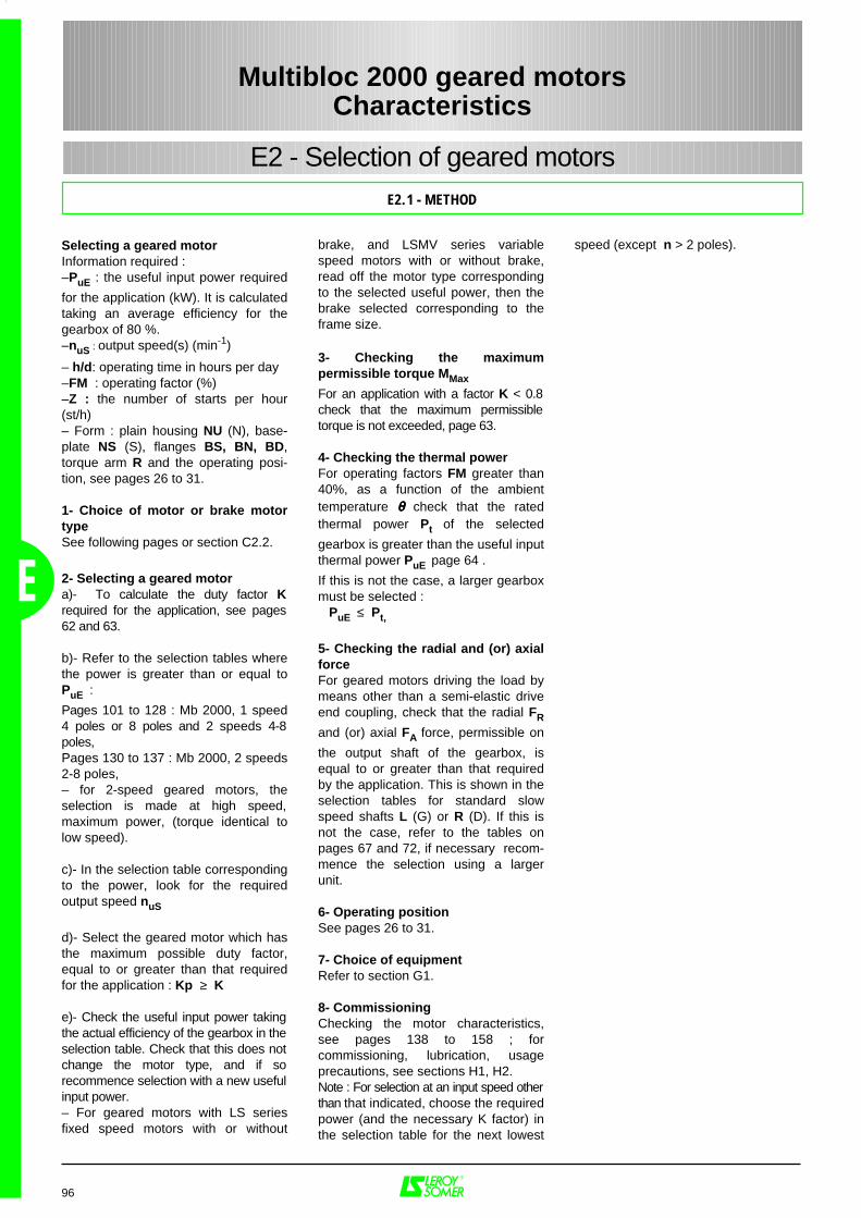
E
speed (except n > 2 poles).
96
Selecting a geared motorInformation required :–PuE : the useful input power required
for the application (kW). It is calculatedtaking an average efficiency for thegearbox of 80 %.–nuS : output speed(s) (min-1)
– h/d: operating time in hours per day–FM : operating factor (%)–Z : the number of starts per hour(st/h)– Form : plain housing NU (N), base-plate NS (S), flanges BS, BN, BD,torque arm R and the operating posi-tion, see pages 26 to 31.
1- Choice of motor or brake motortypeSee following pages or section C2.2.
2- Selecting a geared motora)- To calculate the duty factor Krequired for the application, see pages62 and 63.
b)- Refer to the selection tables wherethe power is greater than or equal toPuE :
Pages 101 to 128 : Mb 2000, 1 speed4 poles or 8 poles and 2 speeds 4-8poles,Pages 130 to 137 : Mb 2000, 2 speeds2-8 poles,– for 2-speed geared motors, theselection is made at high speed,maximum power, (torque identical tolow speed).
c)- In the selection table correspondingto the power, look for the requiredoutput speed nuS
d)- Select the geared motor which hasthe maximum possible duty factor,equal to or greater than that requiredfor the application : Kp ≥ K
e)- Check the useful input power takingthe actual efficiency of the gearbox in theselection table. Check that this does notchange the motor type, and if sorecommence selection with a new usefulinput power.– For geared motors with LS seriesfixed speed motors with or without
brake, and LSMV series variablespeed motors with or without brake,read off the motor type correspondingto the selected useful power, then thebrake selected corresponding to theframe size.
3- Checking the maximumpermissible torque MMax
For an application with a factor K < 0.8check that the maximum permissibletorque is not exceeded, page 63.
4- Checking the thermal powerFor operating factors FM greater than40%, as a function of the ambienttemperature θθθθ check that the ratedthermal power Pt of the selected
gearbox is greater than the useful inputthermal power PuE page 64 .
If this is not the case, a larger gearboxmust be selected : PuE ≤ Pt,
5- Checking the radial and (or) axialforceFor geared motors driving the load bymeans other than a semi-elastic driveend coupling, check that the radial FR
and (or) axial FA force, permissible on
the output shaft of the gearbox, isequal to or greater than that requiredby the application. This is shown in theselection tables for standard slowspeed shafts L (G) or R (D). If this isnot the case, refer to the tables onpages 67 and 72, if necessary recom-mence the selection using a largerunit.
6- Operating position See pages 26 to 31.
7- Choice of equipmentRefer to section G1.
8- CommissioningChecking the motor characteristics,see pages 138 to 158 ; forcommissioning, lubrication, usageprecautions, see sections H1, H2.Note : For selection at an input speed otherthan that indicated, choose the requiredpower (and the necessary K factor) inthe selection table for the next lowest
E2.1 - METHOD
Multibloc 2000 geared motorsCharacteristics
E2 - Selection of geared motors
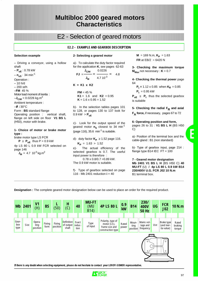
E
97
E2.2 - EXAMPLE AND GEARBOX DESCRIPTION
Multibloc 2000 geared motorsCharacteristics
E2 - Selection of geared motors
Designation : The complete geared motor designation below can be used to place an order for the required product.
If there is any doubt when selecting equipment, please do not hesitate to contact your LEROY-SOMER representative.
Selection example
– Driving a conveyor, using a hollowshaft– PuE : 0.78 kW
– nuS : 34 min-1
Operation : – 10 h/d – 200 st/h–FM 45 %Motor load moment of inertia : –JC/M = 0.0226 kg.m2
Ambient temperature :–θθθθ :::: 30°CForm : BS standard flangeOperating position : vertical shaft,flange on left side on floor V1 BS L(H50), motor with brake.
1- Choice of motor or brake motortype : brake motor type LS FCR
P ≥ PuE thus P = 0.9 kW
4p LS 80 L 0.9 kW FCR selected onpage 146
JM = 4.7 10-3 kg.m2
M = 169 N.m, KP = 1.63
FR at EB/2 = 6420 N
3- Checking the maximum torqueMMax not necessary : K > 0.7
4- Checking the thermal power page64
Pt = 1.12 x 0.85 when Kθθθθ = 0.85
Pt = 0.95 kW
PuE ≤ Pt thus the selected gearbox
is suitable
5- Checking the radial FR and axial
FA force, if necessary, pages 67 to 72
6- Operating position and form, pages 26 to 31 : V1 BS L H (BS H50C)
a)- Position of the terminal box and thecable-gland : B1 (non standard)
b)- Type of gearbox input, page 214 :flange type B14 IEC FT = 100
7 - Geared motor designationMb 2401 V1 BS L H (BS H50 C) 40MU-FT (U) / 4p LS 80 L 0.9 kW B14230/400V U.G. FCR J02 10 N.mB1 terminal box.
2- Selecting a geared motor
a)- To calculate the duty factor requiredfor the application K, see pages 62-63
K = K1 x K2
FM = 45 %K1 = 1.6 and K2 = 0.95K = 1.6 x 0.95 = 1.52
b)- In the selection tables pages 101to 128, or pages 130 to 137 look for0.9 kW > PuE
c)- Look for the output speed of thegeared motor nS closest to 34 min-1
(page 116), 35.6 min-1 is suitable.
d)- duty factor KP ≥ 1.52 page 116.
KP = 1.63 > 1.52
e)- The actual efficiency of theselected gearbox is 0.7. The usefulinput power is therefore :
0.78 x 0.8/0.7 =0.89 kW.The 0.9 kW motor is suitable.
f)- Type of gearbox selected on page116 - Mb 2401 reduction i = 40
JC/M 0.0226FJ = = = 4.8
JM 4.7 10-3
Mb 10 N.m2401 L(50)
H(C) 40
Gear-boxtype
Ratedbrakingtorque
SizeOpera-
tingposition
Fixingposition
Definitionof output
shaft
Exactreduc-
tion
MU-FT(MUB14)
Typeof input
4P LS 80 L
Polarity, type ofmotor (LS),
frame size andconstruction type
0.9kW
Ratedpower
FCRJ02
Brake type(and iner-tia value)
BS
Fixingform
V1(H)
230/400V50 Hz
Mains vol-tage and
frequency
B14
Moun-ting
position
UG
Use
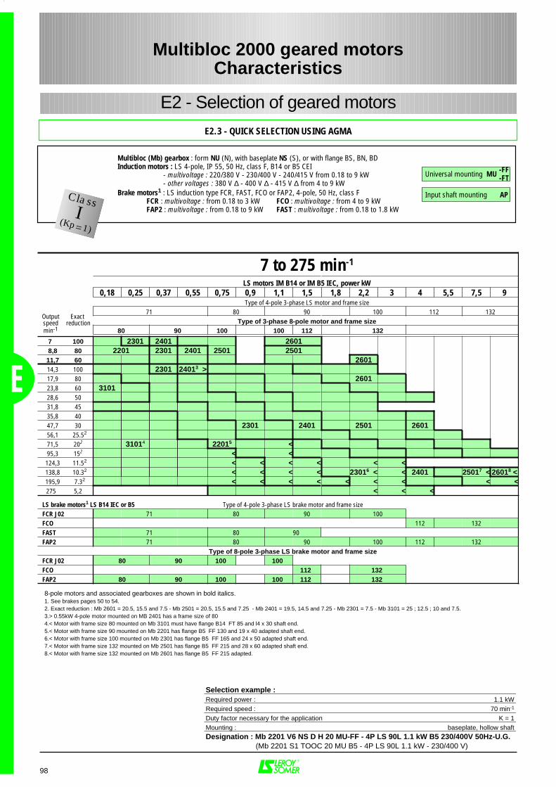
E
98
Multibloc 2000 geared motorsCharacteristics
E2 - Selection of geared motors
E2.3 - QUICK SELECTION USING AGMA
7 to 275 min-1
LS motors IM B14 or IM B5 IEC, power kW0,18 0,25 0,37 0,55 0,75 0,9 1,1 1,5 1,8 2,2 3 4 5,5 7,5 9
Type of 4-pole 3-phase LS motor and frame size 71 80 90 100 112 132
Type of 3-phase 8-pole motor and frame size80 90 100 100 112 132
7 100 2301 2401 26018,8 80 2201 2301 2401 2501 2501
11,7 60 260114,3 100 2301 24013 >17,9 80 260123,8 60 310128,6 5031,8 4535,8 4047,7 30 2301 2401 2501 260156,1 25.52
71,5 202 31014 22015 <95,3 152 < <124,3 11.52 < < < < < <138,8 10.32 < < < < 23016 < < 2401 25017 < 26018 <195,9 7.32 < < < < < < < < <275 5,2 < < <
LS brake motors1 LS B14 IEC or B5 Type of 4-pole 3-phase LS brake motor and frame sizeFCR J02 71 80 90 100FCO 112 132FAST 71 80 90FAP2 71 80 90 100 112 132
Type of 8-pole 3-phase LS brake motor and frame sizeFCR J02 80 90 100 100FCO 112 132FAP2 80 90 100 100 112 132
Outputspeedmin-1
Exact reduction
Selection example :Required power : 1.1 kWRequired speed : 70 min-1
Duty factor necessary for the application K = 1Mounting : baseplate, hollow shaftDesignation : Mb 2201 V6 NS D H 20 MU-FF - 4P LS 90L 1.1 kW B5 230/400V 50Hz-U.G. (Mb 2201 S1 TOOC 20 MU B5 - 4P LS 90L 1.1 kW - 230/400 V)
Multibloc (Mb) gearbox : form NU (N), with baseplate NS (S), or with flange BS, BN, BD Induction motors : LS 4-pole, IP 55, 50 Hz, class F, B14 or B5 CEI
- multivoltage : 220/380 V - 230/400 V - 240/415 V from 0.18 to 9 kW- other voltages : 380 V ∆ - 400 V ∆ - 415 V ∆ from 4 to 9 kW
Brake motors1 : LS induction type FCR, FAST, FCO or FAP2, 4-pole, 50 Hz, class F FCR : multivoltage : from 0.18 to 3 kW FCO : multivoltage : from 4 to 9 kWFAP2 : multivoltage : from 0.18 to 9 kW FAST : multivoltage : from 0.18 to 1.8 kW
Universal mounting MU
Input shaft mounting AP
8-pole motors and associated gearboxes are shown in bold italics.1. See brakes pages 50 to 54.2. Exact reduction : Mb 2601 = 20.5, 15.5 and 7.5 - Mb 2501 = 20.5, 15.5 and 7.25 - Mb 2401 = 19.5, 14.5 and 7.25 - Mb 2301 = 7.5 - Mb 3101 = 25 ; 12.5 ; 10 and 7.5.3.> 0.55kW 4-pole motor mounted on MB 2401 has a frame size of 804.< Motor with frame size 80 mounted on Mb 3101 must have flange B14 FT 85 and l4 x 30 shaft end.5.< Motor with frame size 90 mounted on Mb 2201 has flange B5 FF 130 and 19 x 40 adapted shaft end.6.< Motor with frame size 100 mounted on Mb 2301 has flange B5 FF 165 and 24 x 50 adapted shaft end.7.< Motor with frame size 132 mounted on Mb 2501 has flange B5 FF 215 and 28 x 60 adapted shaft end.8.< Motor with frame size 132 mounted on Mb 2601 has flange B5 FF 215 adapted.
ClassI(Kp=1)
-FF-FT
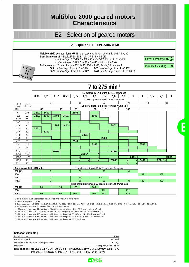
Multibloc (Mb) gearbox : form NU (N), with baseplate NS (S), or with flange BS, BN, BD Induction motors : LS 4-pole, IP 55, 50 Hz, class F, B14 or B5 CEI
- multivoltage : 220/380 V - 230/400 V - 240/415 V from 0.18 to 9 kW- other voltages : 380 V ∆ - 400 V ∆ - 415 V ∆ from 4 to 9 kW
Brake motors1 : LS induction type FCR, FAST, FCO or FAP2, 4-pole, 50 Hz, class F FCR : multivoltage : from 0.18 to 3 kW FCO : multivoltage : from 4 to 9 kWFAP2 : multivoltage : from 0.18 to 9 kW FAST : multivoltage : from 0.18 to 1.8 kW
E
99
E2.3 - QUICK SELECTION USING AGMA
Multibloc 2000 geared motors Characteristics
E2 - Selection of geared motors
7 to 275 min-1
LS motors IM B14 or IM B5 IEC, power kW0,18 0,25 0,37 0,55 0,75 0,9 1,1 1,5 1,8 2,2 3 4 5,5 7,5 9
Type of 3-phase 4-pole motor and frame size 71 80 90 100 112 132
Type of 3-phase 8-pole motor and frame size80 90 100 100 112 132
7 100 2301 2401 26018,8 80 2201 2301 2401 2501 2601
11,7 6014,3 100 >17,9 80 2301 24013 > 260123,8 60 3101 >28,6 50 220131,8 45 240135,8 40 250147,7 30 230156,1 25.52 2401 260171,5 202
95,3 152 31014 2401124,3 11.52 22015 <138,8 10.32 < < 2401 26018 <195,9 7.32 < < < < 23016 < < 2401 25017 < <275 5,2 < <
Brake motors1 LS B14 IEC or B5 Type of 4-pole 3-phase LS brake motor and frame sizeFCR J02 71 80 90 100FCO 112 132FAST 71 80 90FAP2 71 80 90 100 112 132
Type of 8-pole 3-phase LS brake motor and frame sizeFCR J02 80 90 100 100FCO 112 132FAP2 80 90 100 100 112 132
Selection example :Required power : 1.1 kWRequired speed : 70 min-1
Duty factor necessary for the application K = 1,4Mounting : baseplate, hollow shaftDesignation : Mb 2301 B3 NS D H 20 MU-FT - 4P LS 90L 1.1kW B14 230/400V 50Hz - U.G. (Mb 2301 S1 BOOC 20 MU B14 - 4P LS 90L 1.1 kW - 230/400 V)
8-pole motors and associated gearboxes are shown in bold italics.1. See brakes pages 50 to 54.2. Exact reduction : Mb 2601 = 20.5, 15.5 and 7.5 - Mb 2501 = 20.5, 15.5 and 7.25 - Mb 2401 = 19.5, 14.5 and 7.25 - Mb 2301 = 7.5 - Mb 3101 = 25 ; 12.5 ; 10 and 7.5.3.> 0.55kW 4-pole motor mounted on MB 2401 is frame size 804.< Motor with frame size 80 mounted on Mb 3101 must have flange B14 FT 85 and l4 x 30 shaft end5.< Motor with frame size 90 mounted on Mb 2201 has flange B5 FF 130 and 19 x 40 adapted shaft end.6.< Motor with frame size 100 mounted on Mb 2301 has flange B5 FF 165 and 24 x 50 adapted shaft end.7.< Motor with frame size 132 mounted on Mb 2501 has flange B5 FF 215 and 28 x 60 adapted shaft end.8.< Motor with frame size 132 mounted on Mb 2601 has flange B5 FF 215 adapted.
Outputspeedmin-1
Exact reduction
ClassII(Kp=1.4)
Universal mounting MU
Input shaft mounting AP
-FF-FT
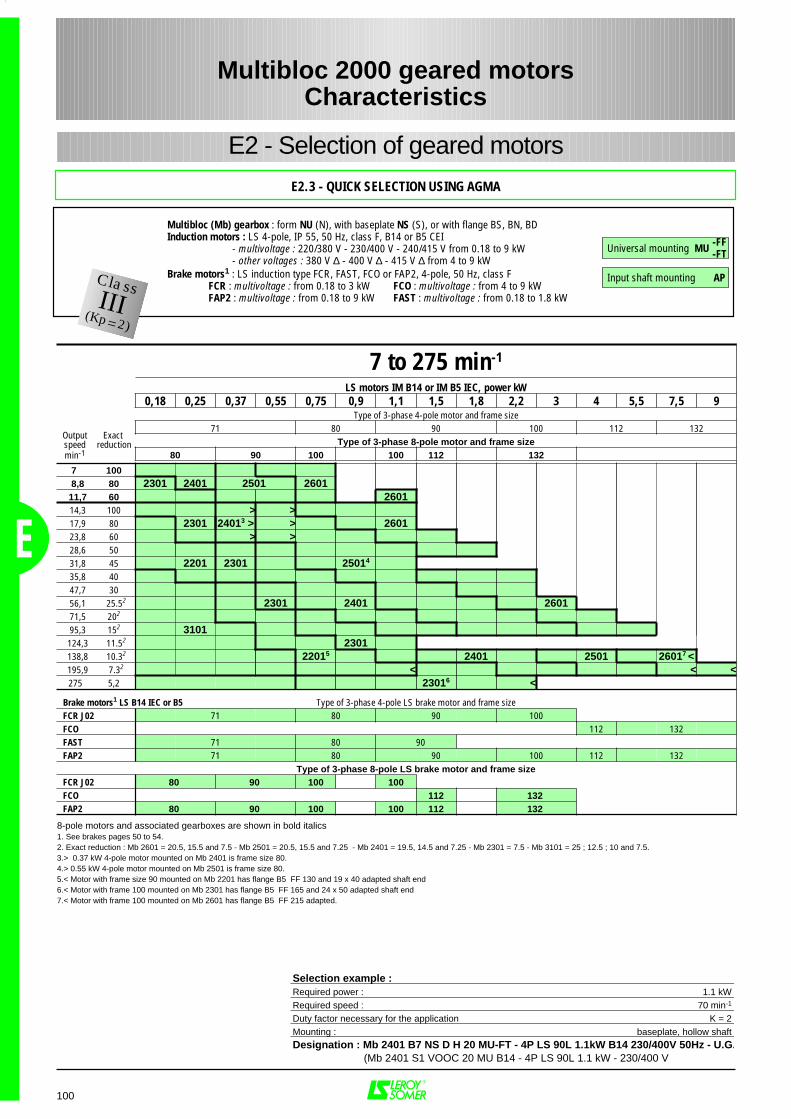
Multibloc (Mb) gearbox : form NU (N), with baseplate NS (S), or with flange BS, BN, BD Induction motors : LS 4-pole, IP 55, 50 Hz, class F, B14 or B5 CEI
- multivoltage : 220/380 V - 230/400 V - 240/415 V from 0.18 to 9 kW- other voltages : 380 V ∆ - 400 V ∆ - 415 V ∆ from 4 to 9 kW
Brake motors1 : LS induction type FCR, FAST, FCO or FAP2, 4-pole, 50 Hz, class F FCR : multivoltage : from 0.18 to 3 kW FCO : multivoltage : from 4 to 9 kWFAP2 : multivoltage : from 0.18 to 9 kW FAST : multivoltage : from 0.18 to 1.8 kW
E
100
Multibloc 2000 geared motorsCharacteristics
E2 - Selection of geared motors
E2.3 - QUICK SELECTION USING AGMA
7 to 275 min-1
LS motors IM B14 or IM B5 IEC, power kW0,18 0,25 0,37 0,55 0,75 0,9 1,1 1,5 1,8 2,2 3 4 5,5 7,5 9
Type of 3-phase 4-pole motor and frame size 71 80 90 100 112 132
Type of 3-phase 8-pole motor and frame size80 90 100 100 112 132
7 1008,8 80 2301 2401 2501 2601
11,7 60 260114,3 100 > >17,9 80 2301 24013 > > 260123,8 60 > >28,6 5031,8 45 2201 2301 25014
35,8 4047,7 3056,1 25.52 2301 2401 260171,5 202
95,3 152 3101124,3 11.52 2301138,8 10.32 22015 2401 2501 26017 <195,9 7.32 < < <275 5,2 23016 <
Brake motors1 LS B14 IEC or B5 Type of 3-phase 4-pole LS brake motor and frame sizeFCR J02 71 80 90 100FCO 112 132FAST 71 80 90FAP2 71 80 90 100 112 132
Type of 3-phase 8-pole LS brake motor and frame sizeFCR J02 80 90 100 100FCO 112 132FAP2 80 90 100 100 112 132
Selection example :Required power : 1.1 kWRequired speed : 70 min-1
Duty factor necessary for the application K = 2Mounting : baseplate, hollow shaftDesignation : Mb 2401 B7 NS D H 20 MU-FT - 4P LS 90L 1.1kW B14 230/400V 50Hz - U.G. (Mb 2401 S1 VOOC 20 MU B14 - 4P LS 90L 1.1 kW - 230/400 V
8-pole motors and associated gearboxes are shown in bold italics 1. See brakes pages 50 to 54.2. Exact reduction : Mb 2601 = 20.5, 15.5 and 7.5 - Mb 2501 = 20.5, 15.5 and 7.25 - Mb 2401 = 19.5, 14.5 and 7.25 - Mb 2301 = 7.5 - Mb 3101 = 25 ; 12.5 ; 10 and 7.5.3.> 0.37 kW 4-pole motor mounted on Mb 2401 is frame size 80.4.> 0.55 kW 4-pole motor mounted on Mb 2501 is frame size 80.5.< Motor with frame size 90 mounted on Mb 2201 has flange B5 FF 130 and 19 x 40 adapted shaft end6.< Motor with frame 100 mounted on Mb 2301 has flange B5 FF 165 and 24 x 50 adapted shaft end7.< Motor with frame 100 mounted on Mb 2601 has flange B5 FF 215 adapted.
Outputspeedmin-1
Exact reduction
ClassIII(Kp=2)
Universal mounting MU
Input shaft mounting AP
-FF-FT
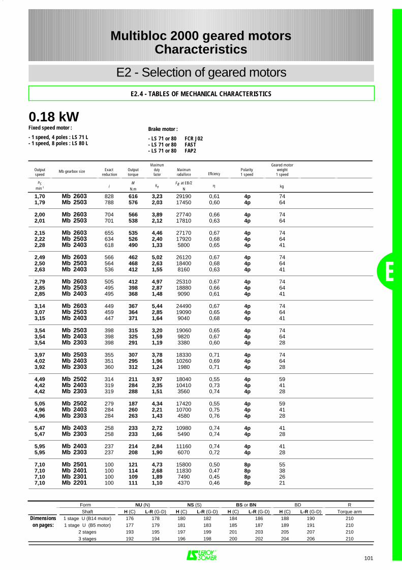
Fixed speed motor :
- 1 speed, 4 poles : LS 71 L- 1 speed, 8 poles : LS 80 L
Brake motor :
- LS 71 or 80 FCR J02- LS 71 or 80 FAST- LS 71 or 80 FAP2
E
101
1,70 Mb 2603 828 616 3,23 29190 0,61 4p 741,79 Mb 2503 788 576 2,03 17450 0,60 4p 64
2,00 Mb 2603 704 566 3,89 27740 0,66 4p 742,01 Mb 2503 701 538 2,12 17810 0,63 4p 64
2,15 Mb 2603 655 535 4,46 27170 0,67 4p 742,22 Mb 2503 634 526 2,40 17920 0,68 4p 642,28 Mb 2403 618 490 1,33 5800 0,65 4p 41
2,49 Mb 2603 566 462 5,02 26120 0,67 4p 742,50 Mb 2503 564 468 2,63 18400 0,68 4p 642,63 Mb 2403 536 412 1,55 8160 0,63 4p 41
2,79 Mb 2603 505 412 4,97 25310 0,67 4p 742,85 Mb 2503 495 398 2,87 18880 0,66 4p 642,85 Mb 2403 495 368 1,48 9090 0,61 4p 41
3,14 Mb 2603 449 367 5,44 24490 0,67 4p 743,07 Mb 2503 459 364 2,85 19090 0,65 4p 643,15 Mb 2403 447 371 1,64 9040 0,68 4p 41
3,54 Mb 2503 398 315 3,20 19060 0,65 4p 743,54 Mb 2403 398 325 1,59 9820 0,67 4p 643,54 Mb 2303 398 291 1,19 3380 0,60 4p 28
3,97 Mb 2503 355 307 3,78 18330 0,71 4p 744,02 Mb 2403 351 295 1,96 10260 0,69 4p 643,92 Mb 2303 360 312 1,24 1980 0,71 4p 28
4,49 Mb 2502 314 211 3,97 18040 0,55 4p 594,42 Mb 2403 319 284 2,35 10410 0,73 4p 414,42 Mb 2303 319 288 1,51 3560 0,74 4p 28
5,05 Mb 2502 279 187 4,34 17420 0,55 4p 594,96 Mb 2403 284 260 2,21 10700 0,75 4p 414,96 Mb 2303 284 263 1,43 4580 0,76 4p 28
5,47 Mb 2403 258 233 2,72 10980 0,74 4p 415,47 Mb 2303 258 233 1,66 5490 0,74 4p 28
5,95 Mb 2403 237 214 2,84 11160 0,74 4p 415,95 Mb 2303 237 208 1,90 6070 0,72 4p 28
7,10 Mb 2501 100 121 4,73 15800 0,50 8p 557,10 Mb 2401 100 114 2,68 11830 0,47 8p 387,10 Mb 2301 100 109 1,89 7490 0,45 8p 267,10 Mb 2201 100 111 1,10 4370 0,46 8p 21
0.18 kW
Outputspeed
Exact reduction
Outputtorque
Maximumduty factor
Maximumradial force Efficiency
Polarity1 speed
Geared motorweight1 speed
nSmin-1 i
MN.m
KPFR at EB/2
Nη kg
Form NU (N) NS (S) BS or BN BD RShaft H (C) L-R (G-D) H (C) L-R (G-D) H (C) L-R (G-D) H (C) L-R (G-D) Torque arm
Dimensions 1 stage U (B14 motor) 176 178 180 182 184 186 188 190 210on pages: 1 stage U (B5 motor) 177 179 181 183 185 187 189 191 210
2 stages 193 195 197 199 201 203 205 207 2103 stages 192 194 196 198 200 202 204 206 210
Multibloc 2000 geared motorsCharacteristics
E2 - Selection of geared motors
E2.4 - TABLES OF MECHANICAL CHARACTERISTICS
Mb gearbox size
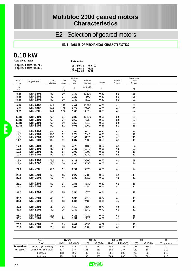
0.18 kW
Form NU (N) NS (S) BS or BN BD RShaft H (C) L-R (G-D) H (C) L-R (G-D) H (C) L-R (G-D) H (C) L-R (G-D) Torque arm
Dimensions 1 stage U (B14 motor) 176 178 180 182 184 186 188 190 210on pages: 1 stage U (B5 motor) 177 179 181 183 185 187 189 191 210
2 stages 193 195 197 199 201 203 205 207 2103 stages 192 194 196 198 200 202 204 206 210
102
8,88 Mb 2401 80 99 3,32 11290 0,51 8p 388,88 Mb 2301 80 97 2,29 7590 0,50 8p 268,88 Mb 2201 80 99 1,42 4610 0,51 8p 21
9,79 Mb 2403 144 133 4,09 10680 0,76 4p 419,79 Mb 2303 144 132 2,74 7260 0,75 4p 289,79 Mb 2203 144 132 1,65 3870 0,75 4p 24
11,83 Mb 2401 60 84 3,80 10290 0,58 8p 3811,83 Mb 2301 60 77 2,67 7730 0,53 8p 2611,83 Mb 2201 60 80 1,58 4910 0,55 8p 2111,83 Mb 3101 60 81 0,93 2260 0,56 8p 15
14,1 Mb 2401 100 63 3,92 9810 0,52 4p 3414,1 Mb 2301 100 62 2,74 7440 0,51 4p 2214,1 Mb 2201 100 62 1,66 5120 0,51 4p 1814,1 Mb 3101 100 61 0,87 2930 0,50 4p 11
17,6 Mb 2401 80 56 4,78 9130 0,57 4p 3417,6 Mb 2301 80 54 3,36 6940 0,55 4p 2217,6 Mb 2201 80 54 2,03 5200 0,55 4p 18 17,6 Mb 3101 80 54 1,09 2930 0,55 4p 11
19,4 Mb 2303 72,5 68 4,33 6600 0,77 4p 2819,4 Mb 2203 72,5 68 2,65 5050 0,77 4p 24
22,0 Mb 2203 64,1 61 2,91 5070 0,78 4p 24
23,5 Mb 2201 60 45 2,27 5080 0,62 4p 1823,5 Mb 3101 60 45 1,38 2710 0,61 4p 11
28,2 Mb 2201 50 37 2,81 4830 0,61 4p 1828,2 Mb 3101 50 39 1,69 2580 0,64 4p 11
31,3 Mb 2201 45 35 3,54 4670 0,64 4p 18
35,3 Mb 2201 40 31 3,30 4510 0,64 4p 1835,3 Mb 3101 40 33 2,33 2430 0,68 4p 11
47,0 Mb 2201 30 26 4,13 4120 0,70 4p 1847,0 Mb 3101 30 26 2,82 2240 0,72 4p 11
55,3 Mb 2201 25,5 23 4,23 3920 0,74 4p 1856,4 Mb 3101 25 24 2,59 2120 0,78 4p 11
70,5 Mb 2201 20 19 6,09 3630 0,79 4p 1870,5 Mb 3101 20 20 3,45 2000 0,80 4p 11
Multibloc 2000 geared motorsCharacteristics
E
E2 - Selection of geared motors
E2.4 - TABLES OF MECHANICAL CHARACTERISTICS
Fixed speed motor :
- 1 speed, 4 poles : LS 71 L- 1 speed, 8 poles : LS 80 L
Brake motor :
- LS 71 or 80 FCR J02- LS 71 or 80 FAST- LS 71 or 80 FAP2
Outputspeed
Exact reduction
Outputtorque
Maximumduty factor
Maximumradial force Efficiency
Polarity1 speed
Geared motorweight1 speed
nSmin-1 i
MN.m
KPFR at EB/2
Nη kg
Mb gearbox size
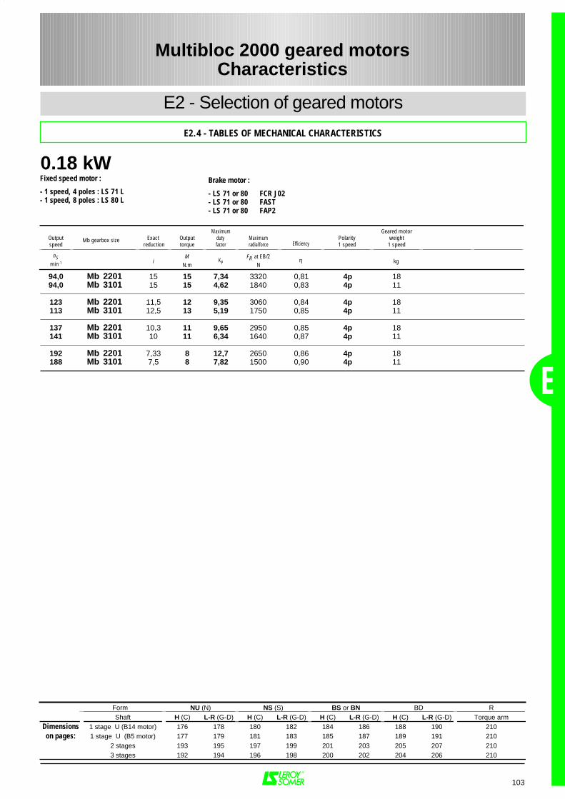
0.18 kW
Form NU (N) NS (S) BS or BN BD RShaft H (C) L-R (G-D) H (C) L-R (G-D) H (C) L-R (G-D) H (C) L-R (G-D) Torque arm
Dimensions 1 stage U (B14 motor) 176 178 180 182 184 186 188 190 210on pages: 1 stage U (B5 motor) 177 179 181 183 185 187 189 191 210
2 stages 193 195 197 199 201 203 205 207 2103 stages 192 194 196 198 200 202 204 206 210
E
103
94,0 Mb 2201 15 15 7,34 3320 0,81 4p 1894,0 Mb 3101 15 15 4,62 1840 0,83 4p 11
123 Mb 2201 11,5 12 9,35 3060 0,84 4p 18113 Mb 3101 12,5 13 5,19 1750 0,85 4p 11
137 Mb 2201 10,3 11 9,65 2950 0,85 4p 18141 Mb 3101 10 11 6,34 1640 0,87 4p 11
192 Mb 2201 7,33 8 12,7 2650 0,86 4p 18188 Mb 3101 7,5 8 7,82 1500 0,90 4p 11
Multibloc 2000 geared motorsCharacteristics
E2 - Selection of geared motors
E2.4 - TABLES OF MECHANICAL CHARACTERISTICS
Fixed speed motor :
- 1 speed, 4 poles : LS 71 L- 1 speed, 8 poles : LS 80 L
Brake motor :
- LS 71 or 80 FCR J02- LS 71 or 80 FAST- LS 71 or 80 FAP2
Outputspeed
Exact reduction
Outputtorque
Maximumduty factor
Maximumradial force Efficiency
Polarity1 speed
Geared motorweight1 speed
nSmin-1 i
MN.m
KPFR at EB/2
Nη kg
Mb gearbox size

0.25 kW
E
104
1,73 Mb 2603 828 840 2,36 27780 0,61 4p 74 4/8p 751,82 Mb 2503 788 787 1,49 14780 0,60 4p 64 4/8p 65
2,04 Mb 2603 704 773 2,85 26510 0,66 4p 74 4/8p 752,05 Mb 2503 701 735 1,55 15560 0,63 4p 64 4/8p 65
2,19 Mb 2603 655 730 3,27 26010 0,67 4p 74 4/8p 752,26 Mb 2503 634 717 1,76 15810 0,68 4p 64 4/8p 65
2,54 Mb 2603 566 631 3,68 25100 0,67 4p 74 4/8p 752,54 Mb 2503 564 638 1,93 16790 0,68 4p 64 4/8p 65
2,84 Mb 2603 505 563 3,64 24390 0,67 4p 74 4/8p 752,90 Mb 2503 495 544 2,10 17760 0,66 4p 64 4/8p 65
3,20 Mb 2603 449 501 3,99 23660 0,67 4p 74 4/8p 753,13 Mb 2503 459 496 2,09 18170 0,65 4p 64 4/8p 653,21 Mb 2403 447 506 1,20 5120 0,68 4p 41 4/8p 42
3,56 Mb 2603 403 456 4,26 22960 0,68 4p 74 4/8p 753,61 Mb 2503 398 430 2,34 18330 0,65 4p 64 4/8p 653,61 Mb 2403 398 444 1,17 7340 0,67 4p 41 4/8p 42
4,14 Mb 2603 347 410 5,50 21970 0,71 4p 74 4/8p 754,04 Mb 2503 355 419 2,77 17620 0,71 4p 64 4/8p 654,09 Mb 2403 351 403 1,43 8360 0,69 4p 41 4/8p 42
4,57 Mb 2502 314 287 2,91 17520 0,55 4p 59 4/8p 604,50 Mb 2403 319 387 1,72 8700 0,73 4p 41 4/8p 42
5,14 Mb 2502 279 255 3,18 16960 0,55 4p 59 4/8p 605,05 Mb 2403 284 354 1,83 9340 0,75 4p 41 4/8p 42
5,72 Mb 2502 251 246 3,54 16370 0,59 4p 59 4/8p 605,56 Mb 2403 258 318 1,99 9940 0,74 4p 41 4/8p 425,56 Mb 2303 258 318 1,29 1260 0,74 4p 28 4/8p 29
6,43 Mb 2502 223 223 3,79 15810 0,60 4p 59 4/8p 606,05 Mb 2403 237 292 2,08 10300 0,74 4p 41 4/8p 426,05 Mb 2303 237 284 1,40 3740 0,72 4p 28 4/8p 29
7,00 Mb 2501 100 160 3,58 15670 0,47 8p 567,00 Mb 2401 100 153 1,98 11620 0,45 8p 397,00 Mb 2301 100 157 1,31 6950 0,46 8p 27
8,75 Mb 2501 80 147 4,37 14550 0,54 8p 568,75 Mb 2401 80 139 2,35 11080 0,51 8p 398,75 Mb 2301 80 136 1,62 7210 0,50 8p 278,75 Mb 2201 80 139 1,01 3640 0,51 8p 23
Form NU (N) NS (S) BS or BN BD RShaft H (C) L-R (G-D) H (C) L-R (G-D) H (C) L-R (G-D) H (C) L-R (G-D) Torque arm
Dimensions 1 stage U (B14 motor) 176 178 180 182 184 186 188 190 210on pages: 1 stage U (B5 motor) 177 179 181 183 185 187 189 191 210
2 stages 193 195 197 199 201 203 205 207 2103 stages 192 194 196 198 200 202 204 206 210
Multibloc 2000 geared motorsCharacteristics
E2 - Selection of geared motors
E2.4 - TABLES OF MECHANICAL CHARACTERISTICS
Fixed speed motor :
- 1 speed, 4 poles : LS 71 L- 1 speed, 8 poles : LS 80 L- 2 speeds, 4/8 poles : LS 71 L
Brake motor :
- LS 71 or 80 FCR J02- LS 71 or 80 FAST- LS 71 or 80 FAP2
Outputspeed
Exactreduction
Outputtorque
Maximum duty factor
Maximum radial force Efficiency
Polarity1 speed
Geared motorweight1 speed
Polarity2 speedsDahlander
Geared motor weight
2 speeds
nSmin-1 i
MN.m
KPFR at EB/2
Nη kg kg
Mb gearbox size
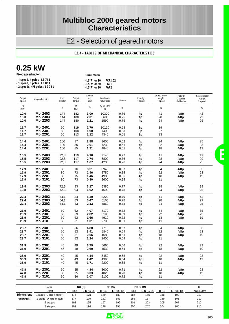
0.25 kW
E
105
10,0 Mb 2403 144 182 3,00 10300 0,76 4p 41 4/8p 4210,0 Mb 2303 144 180 2,01 6600 0,75 4p 28 4/8p 2910,0 Mb 2203 144 180 1,21 1590 0,75 4p 24 4/8p 25
11,7 Mb 2401 60 119 2,70 10120 0,58 8p 3911,7 Mb 2301 60 108 1,90 7490 0,53 8p 2711,7 Mb 2201 60 113 1,12 4340 0,55 8p 23
14,4 Mb 2401 100 87 2,88 9600 0,52 4p 34 4/8p 3514,4 Mb 2301 100 85 2,01 7230 0,51 4p 22 4/8p 2314,4 Mb 2201 100 85 1,21 4840 0,51 4p 18 4/8p 19
15,5 Mb 2403 92,8 119 4,16 9140 0,77 4p 41 4/8p 4215,5 Mb 2303 92,8 117 2,74 6800 0,76 4p 28 4/8p 2915,5 Mb 2203 92,8 117 1,67 4230 0,76 4p 24 4/8p 25
17,9 Mb 2401 80 76 3,51 8940 0,57 4p 34 4/8p 3517,9 Mb 2301 80 73 2,46 6750 0,55 4p 22 4/8p 2317,9 Mb 2201 80 75 1,46 4980 0,56 4p 18 4/8p 1917,9 Mb 3101 80 73 0,80 2600 0,55 4p 11
19,8 Mb 2303 72,5 93 3,17 6380 0,77 4p 28 4/8p 2919,8 Mb 2203 72,5 94 1,92 4690 0,78 4p 24 4/8p 25
22,4 Mb 2403 64,1 84 5,30 8220 0,79 4p 41 4/8p 4222,4 Mb 2303 64,1 83 3,47 6160 0,78 4p 28 4/8p 2922,4 Mb 2203 64,1 83 2,13 4850 0,78 4p 24 4/8p 25
23,9 Mb 2401 60 62 4,07 8170 0,62 4p 34 4/8p 3523,9 Mb 2301 60 59 2,82 6190 0,59 4p 22 4/8p 2323,9 Mb 2201 60 62 1,66 4910 0,62 4p 18 4/8p 1923,9 Mb 3101 60 61 1,01 2700 0,61 4p 11
28,7 Mb 2401 50 56 4,80 7710 0,67 4p 34 4/8p 3528,7 Mb 2301 50 53 3,41 5840 0,64 4p 22 4/8p 2328,7 Mb 2201 50 51 2,06 4680 0,61 4p 18 4/8p 1928,7 Mb 3101 50 53 1,24 2400 0,64 4p 11
31,9 Mb 2301 45 49 3,79 5660 0,66 4p 22 4/8p 2331,9 Mb 2201 45 48 2,60 4530 0,64 4p 18 4/8p 19
35,9 Mb 2301 40 45 4,14 5450 0,68 4p 22 4/8p 2335,9 Mb 2201 40 43 2,42 4390 0,64 4p 18 4/8p 1935,9 Mb 3101 40 45 1,71 2200 0,68 4p 11
47,8 Mb 2301 30 35 4,84 5000 0,71 4p 22 4/8p 2347,8 Mb 2201 30 35 3,03 4020 0,70 4p 18 4/8p 1947,8 Mb 3101 30 36 2,07 2100 0,72 4p 11
Multibloc 2000 geared motorsCharacteristics
E2 - Selection of geared motors
E2.4 - TABLES OF MECHANICAL CHARACTERISTICS
Fixed speed motor :
- 1 speed, 4 poles : LS 71 L- 1 speed, 8 poles : LS 80 L- 2 speeds, 4/8 poles : LS 71 L
Brake motor :
- LS 71 or 80 FCR J02- LS 71 or 80 FAST- LS 71 or 80 FAP2
Outputspeed
Exact reduction
Output torque
Maximum dutyfactor
Maximumradial force Efficiency
Polarity1 speed
Geared motorweight1 speed
Polarity2 speedsDahlander
Geared motorweight
2 speeds
nSmin-1 i
MN.m
KPFR at EB/2
Nη kg kg
Mb gearbox size
Form NU (N) NS (S) BS or BN BD RShaft H (C) L-R (G-D) H (C) L-R (G-D) H (C) L-R (G-D) H (C) L-R (G-D) Torque arm
Dimensions 1 stage U (B14 motor) 176 178 180 182 184 186 188 190 210on pages: 1 stage U (B5 motor) 177 179 181 183 185 187 189 191 210
2 stages 193 195 197 199 201 203 205 207 2103 stages 192 194 196 198 200 202 204 206 210
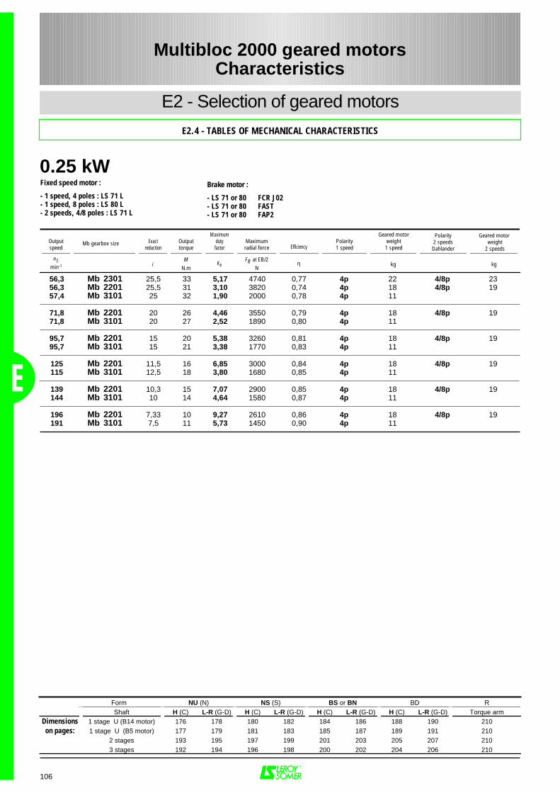
0.25 kW
E
106
56,3 Mb 2301 25,5 33 5,17 4740 0,77 4p 22 4/8p 2356,3 Mb 2201 25,5 31 3,10 3820 0,74 4p 18 4/8p 1957,4 Mb 3101 25 32 1,90 2000 0,78 4p 11
71,8 Mb 2201 20 26 4,46 3550 0,79 4p 18 4/8p 1971,8 Mb 3101 20 27 2,52 1890 0,80 4p 11
95,7 Mb 2201 15 20 5,38 3260 0,81 4p 18 4/8p 1995,7 Mb 3101 15 21 3,38 1770 0,83 4p 11
125 Mb 2201 11,5 16 6,85 3000 0,84 4p 18 4/8p 19115 Mb 3101 12,5 18 3,80 1680 0,85 4p 11
139 Mb 2201 10,3 15 7,07 2900 0,85 4p 18 4/8p 19144 Mb 3101 10 14 4,64 1580 0,87 4p 11
196 Mb 2201 7,33 10 9,27 2610 0,86 4p 18 4/8p 19191 Mb 3101 7,5 11 5,73 1450 0,90 4p 11
Multibloc 2000 geared motorsCharacteristics
E2 - Selection of geared motors
E2.4 - TABLES OF MECHANICAL CHARACTERISTICS
Fixed speed motor :
- 1 speed, 4 poles : LS 71 L- 1 speed, 8 poles : LS 80 L- 2 speeds, 4/8 poles : LS 71 L
Brake motor :
- LS 71 or 80 FCR J02- LS 71 or 80 FAST- LS 71 or 80 FAP2
Outputspeed
Exactreduction
Outputtorque
Maximumdutyfactor
Maximumradial force Efficiency
Polarity1 speed
Geared motorweight1 speed
Polarity2 speedsDahlander
Geared motor weight
2 speeds
nSmin-1 i
MN.m
KPFR at EB/2
Nη kg kg
Mb gearbox size
Form NU (N) NS (S) BS or BN BD RShaft H (C) L-R (G-D) H (C) L-R (G-D) H (C) L-R (G-D) H (C) L-R (G-D) Torque arm
Dimensions 1 stage U (B14 motor) 176 178 180 182 184 186 188 190 210on pages: 1 stage U (B5 motor) 177 179 181 183 185 187 189 191 210
2 stages 193 195 197 199 201 203 205 207 2103 stages 192 194 196 198 200 202 204 206 210
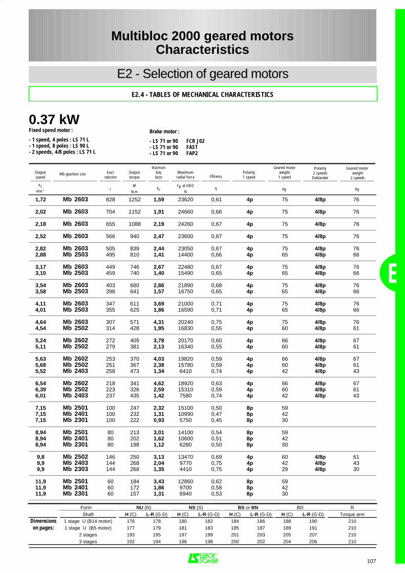
0.37 kW
E
107
1,72 Mb 2603 828 1252 1,59 23620 0,61 4p 75 4/8p 76
2,02 Mb 2603 704 1152 1,91 24660 0,66 4p 75 4/8p 76
2,18 Mb 2603 655 1088 2,19 24260 0,67 4p 75 4/8p 76
2,52 Mb 2603 566 940 2,47 23600 0,67 4p 75 4/8p 76
2,82 Mb 2603 505 839 2,44 23050 0,67 4p 75 4/8p 762,88 Mb 2503 495 810 1,41 14400 0,66 4p 65 4/8p 66
3,17 Mb 2603 449 746 2,67 22480 0,67 4p 75 4/8p 763,10 Mb 2503 459 740 1,40 15490 0,65 4p 65 4/8p 66
3,54 Mb 2603 403 680 2,86 21890 0,68 4p 75 4/8p 763,58 Mb 2503 398 641 1,57 16750 0,65 4p 65 4/8p 66
4,11 Mb 2603 347 611 3,69 21000 0,71 4p 75 4/8p 764,01 Mb 2503 355 625 1,86 16590 0,71 4p 65 4/8p 66
4,64 Mb 2603 307 571 4,31 20240 0,75 4p 75 4/8p 764,54 Mb 2502 314 428 1,95 16830 0,55 4p 60 4/8p 61
5,24 Mb 2602 272 405 3,78 20170 0,60 4p 66 4/8p 675,11 Mb 2502 279 381 2,13 16340 0,55 4p 60 4/8p 61
5,63 Mb 2602 253 370 4,03 19820 0,59 4p 66 4/8p 675,68 Mb 2502 251 367 2,38 15780 0,59 4p 60 4/8p 615,52 Mb 2403 258 473 1,34 6410 0,74 4p 42 4/8p 43
6,54 Mb 2602 218 341 4,62 18920 0,63 4p 66 4/8p 676,39 Mb 2502 223 326 2,59 15310 0,59 4p 60 4/8p 616,01 Mb 2403 237 435 1,42 7580 0,74 4p 42 4/8p 43
7,15 Mb 2501 100 247 2,32 15100 0,50 8p 597,15 Mb 2401 100 232 1,31 10990 0,47 8p 427,15 Mb 2301 100 222 0,93 5750 0,45 8p 30
8,94 Mb 2501 80 213 3,01 14100 0,54 8p 598,94 Mb 2401 80 202 1,62 10600 0,51 8p 428,94 Mb 2301 80 198 1,12 6280 0,50 8p 30
9,8 Mb 2502 146 250 3,13 13470 0,69 4p 60 4/8p 619,9 Mb 2403 144 268 2,04 9770 0,75 4p 42 4/8p 439,9 Mb 2303 144 268 1,35 4410 0,75 4p 29 4/8p 30
11,9 Mb 2501 60 184 3,43 12860 0,62 8p 5911,9 Mb 2401 60 172 1,86 9700 0,58 8p 4211,9 Mb 2301 60 157 1,31 6940 0,53 8p 30
Form NU (N) NS (S) BS or BN BD RShaft H (C) L-R (G-D) H (C) L-R (G-D) H (C) L-R (G-D) H (C) L-R (G-D) Torque arm
Dimensions 1 stage U (B14 motor) 176 178 180 182 184 186 188 190 210on pages: 1 stage U (B5 motor) 177 179 181 183 185 187 189 191 210
2 stages 193 195 197 199 201 203 205 207 2103 stages 192 194 196 198 200 202 204 206 210
Multibloc 2000 geared motorsCharacteristics
E2 - Selection of geared motors
E2.4 - TABLES OF MECHANICAL CHARACTERISTICS
Fixed speed motor :
- 1 speed, 4 poles : LS 71 L- 1 speed, 8 poles : LS 90 L- 2 speeds, 4/8 poles : LS 71 L
Brake motor :
- LS 71 or 90 FCR J02- LS 71 or 90 FAST- LS 71 or 90 FAP2
Outputspeed
Exact reduction
Outputtorque
Maximumdutyfactor
Maximumradial force Efficiency
Polarity1 speed
Geared motorweight1 speed
Polarity2 speedsDahlander
Geared motor weight
2 speeds
nSmin-1 i
MN.m
KPFR at EB/2
Nη kg kg
Mb gearbox size
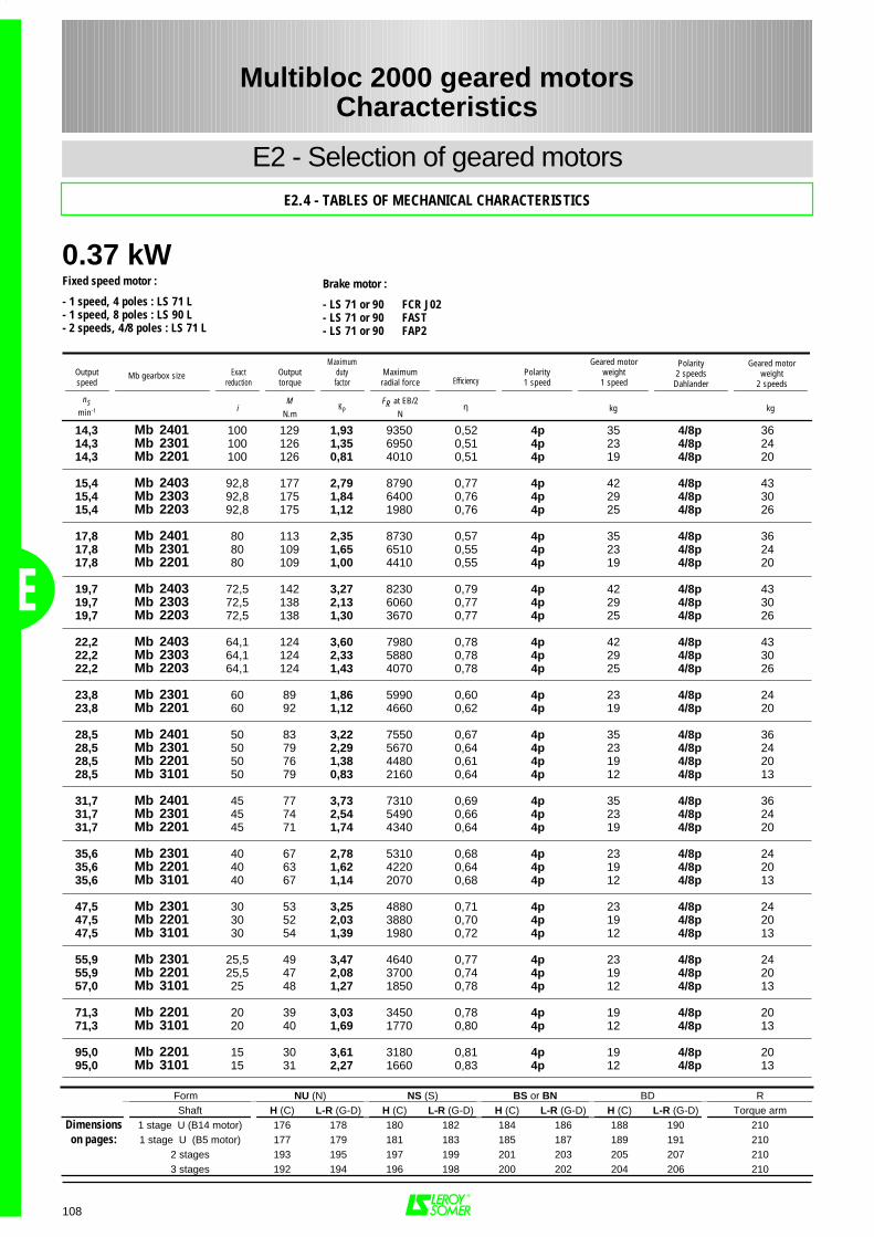
0.37 kW
E
108
14,3 Mb 2401 100 129 1,93 9350 0,52 4p 35 4/8p 3614,3 Mb 2301 100 126 1,35 6950 0,51 4p 23 4/8p 2414,3 Mb 2201 100 126 0,81 4010 0,51 4p 19 4/8p 20
15,4 Mb 2403 92,8 177 2,79 8790 0,77 4p 42 4/8p 4315,4 Mb 2303 92,8 175 1,84 6400 0,76 4p 29 4/8p 3015,4 Mb 2203 92,8 175 1,12 1980 0,76 4p 25 4/8p 26
17,8 Mb 2401 80 113 2,35 8730 0,57 4p 35 4/8p 3617,8 Mb 2301 80 109 1,65 6510 0,55 4p 23 4/8p 2417,8 Mb 2201 80 109 1,00 4410 0,55 4p 19 4/8p 20
19,7 Mb 2403 72,5 142 3,27 8230 0,79 4p 42 4/8p 4319,7 Mb 2303 72,5 138 2,13 6060 0,77 4p 29 4/8p 3019,7 Mb 2203 72,5 138 1,30 3670 0,77 4p 25 4/8p 26
22,2 Mb 2403 64,1 124 3,60 7980 0,78 4p 42 4/8p 4322,2 Mb 2303 64,1 124 2,33 5880 0,78 4p 29 4/8p 3022,2 Mb 2203 64,1 124 1,43 4070 0,78 4p 25 4/8p 26
23,8 Mb 2301 60 89 1,86 5990 0,60 4p 23 4/8p 2423,8 Mb 2201 60 92 1,12 4660 0,62 4p 19 4/8p 20
28,5 Mb 2401 50 83 3,22 7550 0,67 4p 35 4/8p 3628,5 Mb 2301 50 79 2,29 5670 0,64 4p 23 4/8p 2428,5 Mb 2201 50 76 1,38 4480 0,61 4p 19 4/8p 2028,5 Mb 3101 50 79 0,83 2160 0,64 4p 12 4/8p 13
31,7 Mb 2401 45 77 3,73 7310 0,69 4p 35 4/8p 3631,7 Mb 2301 45 74 2,54 5490 0,66 4p 23 4/8p 2431,7 Mb 2201 45 71 1,74 4340 0,64 4p 19 4/8p 20
35,6 Mb 2301 40 67 2,78 5310 0,68 4p 23 4/8p 2435,6 Mb 2201 40 63 1,62 4220 0,64 4p 19 4/8p 2035,6 Mb 3101 40 67 1,14 2070 0,68 4p 12 4/8p 13
47,5 Mb 2301 30 53 3,25 4880 0,71 4p 23 4/8p 2447,5 Mb 2201 30 52 2,03 3880 0,70 4p 19 4/8p 2047,5 Mb 3101 30 54 1,39 1980 0,72 4p 12 4/8p 13
55,9 Mb 2301 25,5 49 3,47 4640 0,77 4p 23 4/8p 2455,9 Mb 2201 25,5 47 2,08 3700 0,74 4p 19 4/8p 2057,0 Mb 3101 25 48 1,27 1850 0,78 4p 12 4/8p 13
71,3 Mb 2201 20 39 3,03 3450 0,78 4p 19 4/8p 2071,3 Mb 3101 20 40 1,69 1770 0,80 4p 12 4/8p 13
95,0 Mb 2201 15 30 3,61 3180 0,81 4p 19 4/8p 2095,0 Mb 3101 15 31 2,27 1660 0,83 4p 12 4/8p 13
Form NU (N) NS (S) BS or BN BD RShaft H (C) L-R (G-D) H (C) L-R (G-D) H (C) L-R (G-D) H (C) L-R (G-D) Torque arm
Dimensions 1 stage U (B14 motor) 176 178 180 182 184 186 188 190 210on pages: 1 stage U (B5 motor) 177 179 181 183 185 187 189 191 210
2 stages 193 195 197 199 201 203 205 207 2103 stages 192 194 196 198 200 202 204 206 210
Multibloc 2000 geared motorsCharacteristics
E2 - Selection of geared motorsE2.4 - TABLES OF MECHANICAL CHARACTERISTICS
Fixed speed motor :
- 1 speed, 4 poles : LS 71 L- 1 speed, 8 poles : LS 90 L- 2 speeds, 4/8 poles : LS 71 L
Brake motor :
- LS 71 or 90 FCR J02- LS 71 or 90 FAST- LS 71 or 90 FAP2
Outputspeed
Exactreduction
Outputtorque
Maximumdutyfactor
Maximumradial force Efficiency
Polarity1 speed
Geared motorweight1 speed
Polarity2 speedsDahlander
Geared motorweight
2 speeds
nSmin-1 i
MN.m
KPFR at EB/2
Nη kg kg
Mb gearbox size
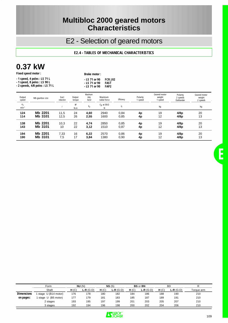
0.37 kW
E
109
124 Mb 2201 11,5 24 4,60 2940 0,84 4p 19 4/8p 20114 Mb 3101 12,5 26 2,55 1600 0,85 4p 12 4/8p 13
138 Mb 2201 10,3 22 4,74 2850 0,85 4p 19 4/8p 20143 Mb 3101 10 22 3,12 1510 0,87 4p 12 4/8p 13
194 Mb 2201 7,33 16 6,22 2570 0,86 4p 19 4/8p 20190 Mb 3101 7,5 17 3,84 1380 0,90 4p 12 4/8p 13
Form NU (N) NS (S) BS or BN BD RShaft H (C) L-R (G-D) H (C) L-R (G-D) H (C) L-R (G-D) H (C) L-R (G-D) Torque arm
Dimensions 1 stage U (B14 motor) 176 178 180 182 184 186 188 190 210on pages: 1 stage U (B5 motor) 177 179 181 183 185 187 189 191 210
2 stages 193 195 197 199 201 203 205 207 2103 stages 192 194 196 198 200 202 204 206 210
Multibloc 2000 geared motorsCharacteristics
E2 - Selection of geared motors
E2.4 - TABLES OF MECHANICAL CHARACTERISTICS
Fixed speed motor :
- 1 speed, 4 poles : LS 71 L- 1 speed, 8 poles : LS 90 L- 2 speeds, 4/8 poles : LS 71 L
Brake motor :
- LS 71 or 90 FCR J02- LS 71 or 90 FAST- LS 71 or 90 FAP2
Outputspeed
Exact reduction
Output torque
Maximum duty factor
Maximum radial force Efficiency
Polarity1 speed
Geared motorweight1 speed
Polarity2 speedsDahlander
Geared motor weight
2 speeds
nSmin-1 i
MN.m
KPFR at EB/2
Nη kg kg
Mb gearbox size
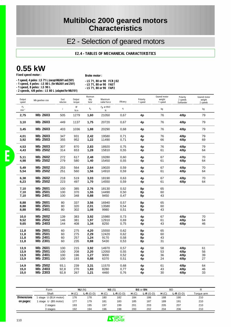
0.55 kW
2,75 Mb 2603 505 1279 1,60 21050 0,67 4p 76 4/8p 79
3,10 Mb 2603 449 1137 1,75 20720 0,67 4p 76 4/8p 79
3,45 Mb 2603 403 1036 1,88 20290 0,68 4p 76 4/8p 79
4,01 Mb 2603 347 931 2,42 19580 0,71 4p 76 4/8p 793,92 Mb 2503 355 952 1,22 11490 0,71 4p 66 4/8p 69
4,53 Mb 2603 307 870 2,83 18920 0,75 4p 76 4/8p 794,43 Mb 2502 314 653 1,28 15810 0,55 4p 61 4/8p 64
5,11 Mb 2602 272 617 2,48 19280 0,60 4p 67 4/8p 704,98 Mb 2502 279 580 1,40 15450 0,55 4p 61 4/8p 64
5,49 Mb 2602 253 564 2,64 19020 0,59 4p 67 4/8p 705,54 Mb 2502 251 560 1,56 14910 0,59 4p 61 4/8p 64
6,38 Mb 2602 218 519 3,03 18190 0,63 4p 67 4/8p 706,23 Mb 2502 223 497 1,70 14550 0,59 4p 61 4/8p 64
7,10 Mb 2601 100 385 2,76 18130 0,52 8p 657,10 Mb 2501 100 370 1,55 14490 0,50 8p 607,10 Mb 2401 100 348 0,88 9450 0,47 8p 43
8,88 Mb 2601 80 337 3,56 16940 0,57 8p 658,88 Mb 2501 80 320 2,01 13580 0,54 8p 608,88 Mb 2401 80 302 1,08 9980 0,51 8p 43
10,0 Mb 2602 139 383 3,92 15980 0,73 4p 67 4/8p 709,52 Mb 2502 146 381 1,97 12910 0,69 4p 61 4/8p 649,65 Mb 2403 144 408 1,34 8250 0,75 4p 43 4/8p 46
11,8 Mb 2601 60 275 4,20 15550 0,62 8p 6511,8 Mb 2501 60 275 2,29 12420 0,62 8p 6011,8 Mb 2401 60 257 1,24 9170 0,58 8p 4311,8 Mb 2301 60 235 0,88 5430 0,53 8p 31
13,9 Mb 2601 100 215 3,92 14970 0,57 4p 58 4/8p 6113,9 Mb 2501 100 208 2,20 12050 0,55 4p 53 4/8p 5613,9 Mb 2401 100 196 1,27 9000 0,52 4p 36 4/8p 3913,9 Mb 2301 100 193 0,88 6370 0,51 4p 24 4/8p 27
14,9 Mb 2502 93,1 239 3,31 11570 0,68 4p 61 4/8p 6415,0 Mb 2403 92,8 270 1,83 8280 0,77 4p 43 4/8p 4615,0 Mb 2303 92,8 267 1,21 4460 0,76 4p 30 4/8p 33
E
110
Form NU (N) NS (S) BS or BN BD RShaft H (C) L-R (G-D) H (C) L-R (G-D) H (C) L-R (G-D) H (C) L-R (G-D) Torque arm
Dimensions 1 stage U (B14 motor) 176 178 180 182 184 186 188 190 210on pages: 1 stage U (B5 motor) 177 179 181 183 185 187 189 191 210
2 stages 193 195 197 199 201 203 205 207 2103 stages 192 194 196 198 200 202 204 206 210
Multibloc 2000 geared motorsCharacteristics
E2 - Selection of geared motors
E2.4 - TABLES OF MECHANICAL CHARACTERISTICS
Fixed speed motor :
- 1 speed, 4 poles : LS 71 L (except Mb2601 and 2501)- 1 speed, 4 poles : LS 80 L (for Mb2601 and 2501)- 1 speed, 8 poles : LS 90 L- 2 speeds, 4/8 poles : LS 80 L (adapted for Mb3101)
Brake motor :
- LS 71, 80 or 90 FCR J02- LS 71, 80 or 90 FAST- LS 71, 80 or 90 FAP2
Outputspeed
Exactreduction
Output torque
Maximumdutyfactor
Maximum radial force Efficiency
Polarity1 speed
Geared motorweight1 speed
Polarity2 speedsDahlander
Geared motorweight
2 speeds
nSmin-1 i
MN.m
KPFR at EB/2
Nη kg kg
Mb gearbox size
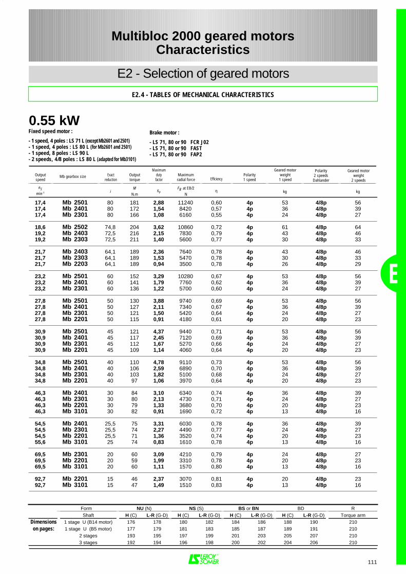
0.55 kW
E
111
17,4 Mb 2501 80 181 2,88 11240 0,60 4p 53 4/8p 5617,4 Mb 2401 80 172 1,54 8420 0,57 4p 36 4/8p 3917,4 Mb 2301 80 166 1,08 6160 0,55 4p 24 4/8p 27
18,6 Mb 2502 74,8 204 3,62 10860 0,72 4p 61 4/8p 6419,2 Mb 2403 72,5 216 2,15 7830 0,79 4p 43 4/8p 4619,2 Mb 2303 72,5 211 1,40 5600 0,77 4p 30 4/8p 33
21,7 Mb 2403 64,1 189 2,36 7640 0,78 4p 43 4/8p 4621,7 Mb 2303 64,1 189 1,53 5470 0,78 4p 30 4/8p 3321,7 Mb 2203 64,1 189 0,94 3500 0,78 4p 26 4/8p 29
23,2 Mb 2501 60 152 3,29 10280 0,67 4p 53 4/8p 5623,2 Mb 2401 60 141 1,79 7760 0,62 4p 36 4/8p 3923,2 Mb 2301 60 136 1,22 5700 0,60 4p 24 4/8p 27
27,8 Mb 2501 50 130 3,88 9740 0,69 4p 53 4/8p 5627,8 Mb 2401 50 127 2,11 7340 0,67 4p 36 4/8p 3927,8 Mb 2301 50 121 1,50 5420 0,64 4p 24 4/8p 2727,8 Mb 2201 50 115 0,91 4180 0,61 4p 20 4/8p 23
30,9 Mb 2501 45 121 4,37 9440 0,71 4p 53 4/8p 5630,9 Mb 2401 45 117 2,45 7120 0,69 4p 36 4/8p 3930,9 Mb 2301 45 112 1,67 5270 0,66 4p 24 4/8p 2730,9 Mb 2201 45 109 1,14 4060 0,64 4p 20 4/8p 23
34,8 Mb 2501 40 110 4,78 9110 0,73 4p 53 4/8p 5634,8 Mb 2401 40 106 2,59 6890 0,70 4p 36 4/8p 3934,8 Mb 2301 40 103 1,82 5100 0,68 4p 24 4/8p 2734,8 Mb 2201 40 97 1,06 3970 0,64 4p 20 4/8p 23
46,3 Mb 2401 30 84 3,10 6340 0,74 4p 36 4/8p 3946,3 Mb 2301 30 80 2,13 4730 0,71 4p 24 4/8p 2746,3 Mb 2201 30 79 1,33 3680 0,70 4p 20 4/8p 2346,3 Mb 3101 30 82 0,91 1690 0,72 4p 13 4/8p 16
54,5 Mb 2401 25,5 75 3,31 6030 0,78 4p 36 4/8p 3954,5 Mb 2301 25,5 74 2,27 4490 0,77 4p 24 4/8p 2754,5 Mb 2201 25,5 71 1,36 3520 0,74 4p 20 4/8p 2355,6 Mb 3101 25 74 0,83 1610 0,78 4p 13 4/8p 16
69,5 Mb 2301 20 60 3,09 4210 0,79 4p 24 4/8p 2769,5 Mb 2201 20 59 1,99 3310 0,78 4p 20 4/8p 2369,5 Mb 3101 20 60 1,11 1570 0,80 4p 13 4/8p 16
92,7 Mb 2201 15 46 2,37 3070 0,81 4p 20 4/8p 2392,7 Mb 3101 15 47 1,49 1510 0,83 4p 13 4/8p 16
Form NU (N) NS (S) BS or BN BD RShaft H (C) L-R (G-D) H (C) L-R (G-D) H (C) L-R (G-D) H (C) L-R (G-D) Torque arm
Dimensions 1 stage U (B14 motor) 176 178 180 182 184 186 188 190 210on pages: 1 stage U (B5 motor) 177 179 181 183 185 187 189 191 210
2 stages 193 195 197 199 201 203 205 207 2103 stages 192 194 196 198 200 202 204 206 210
Multibloc 2000 geared motorsCharacteristics
E2 - Selection of geared motors
E2.4 - TABLES OF MECHANICAL CHARACTERISTICS
Fixed speed motor :
- 1 speed, 4 poles : LS 71 L (except Mb2601 and 2501)- 1 speed, 4 poles : LS 80 L (for Mb2601 and 2501)- 1 speed, 8 poles : LS 90 L- 2 speeds, 4/8 poles : LS 80 L (adapted for Mb3101)
Brake motor :
- LS 71, 80 or 90 FCR J02- LS 71, 80 or 90 FAST- LS 71, 80 or 90 FAP2
Outputspeed
Exactreduction
Outputtorque
Maximumdutyfactor
Maximumradial force Efficiency
Polarity1 speed
Geared motorweight1 speed
Polarity2 speedsDahlander
Geared motorweight
2 speeds
nSmin-1 i
MN.m
KPFR at EB/2
Nη kg kg
Mb gearbox size
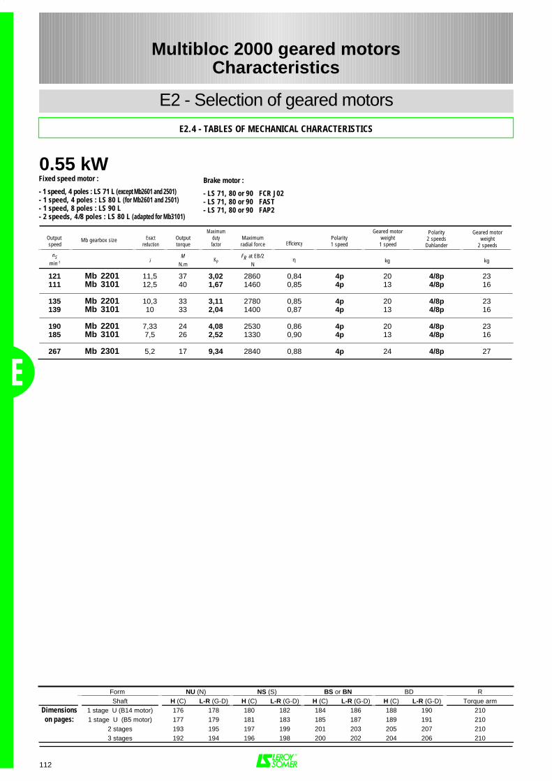
0.55 kW
E
112
121 Mb 2201 11,5 37 3,02 2860 0,84 4p 20 4/8p 23111 Mb 3101 12,5 40 1,67 1460 0,85 4p 13 4/8p 16
135 Mb 2201 10,3 33 3,11 2780 0,85 4p 20 4/8p 23139 Mb 3101 10 33 2,04 1400 0,87 4p 13 4/8p 16
190 Mb 2201 7,33 24 4,08 2530 0,86 4p 20 4/8p 23185 Mb 3101 7,5 26 2,52 1330 0,90 4p 13 4/8p 16
267 Mb 2301 5,2 17 9,34 2840 0,88 4p 24 4/8p 27
Form NU (N) NS (S) BS or BN BD RShaft H (C) L-R (G-D) H (C) L-R (G-D) H (C) L-R (G-D) H (C) L-R (G-D) Torque arm
Dimensions 1 stage U (B14 motor) 176 178 180 182 184 186 188 190 210on pages: 1 stage U (B5 motor) 177 179 181 183 185 187 189 191 210
2 stages 193 195 197 199 201 203 205 207 2103 stages 192 194 196 198 200 202 204 206 210
Multibloc 2000 geared motorsCharacteristics
E2 - Selection of geared motors
E2.4 - TABLES OF MECHANICAL CHARACTERISTICS
Fixed speed motor :
- 1 speed, 4 poles : LS 71 L (except Mb2601 and 2501)- 1 speed, 4 poles : LS 80 L (for Mb2601 and 2501)- 1 speed, 8 poles : LS 90 L- 2 speeds, 4/8 poles : LS 80 L (adapted for Mb3101)
Brake motor :
- LS 71, 80 or 90 FCR J02- LS 71, 80 or 90 FAST- LS 71, 80 or 90 FAP2
Output speed
Exactreduction
Outputtorque
Maximumdutyfactor
Maximumradial force Efficiency
Polarity1 speed
Geared motorweight1 speed
Polarity2 speedsDahlander
Geared motorweight
2 speeds
nSmin-1 i
MN.m
KPFR at EB/2
Nη kg kg
Mb gearbox size
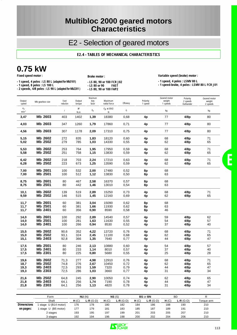
0.75 kW
E
113
3,47 Mb 2603 403 1402 1,39 18380 0,68 4p 77 4/8p 80
4,03 Mb 2603 347 1260 1,79 17860 0,71 4p 77 4/8p 80
4,56 Mb 2603 307 1178 2,09 17310 0,75 4p 77 4/8p 80
5,15 Mb 2602 272 835 1,83 18120 0,60 4p 68 4/8p 715,02 Mb 2502 279 785 1,03 14330 0,55 4p 62 4/8p 65
5,53 Mb 2602 253 764 1,95 17950 0,59 4p 68 4/8p 715,58 Mb 2502 251 758 1,15 13830 0,59 4p 62 4/8p 65
6,42 Mb 2602 218 703 2,24 17210 0,63 4p 68 4/8p 716,28 Mb 2502 223 673 1,25 13590 0,59 4p 62 4/8p 65
7,00 Mb 2601 100 532 2,00 17480 0,52 8p 687,00 Mb 2501 100 512 1,12 13830 0,50 8p 63
8,75 Mb 2601 80 467 2,58 16370 0,57 8p 688,75 Mb 2501 80 442 1,46 13010 0,54 8p 63
10,1 Mb 2602 139 519 2,89 15250 0,73 4p 68 4/8p 719,59 Mb 2502 146 515 1,45 12160 0,69 4p 62 4/8p 65
11,7 Mb 2601 60 381 3,04 15090 0,62 8p 6811,7 Mb 2501 60 381 1,66 11930 0,62 8p 6311,7 Mb 2401 60 356 0,90 8590 0,58 8p 46
14,0 Mb 2601 100 292 2,89 14540 0,57 4p 59 4/8p 6214,0 Mb 2501 100 281 1,63 11630 0,55 4p 54 4/8p 5714,0 Mb 2401 100 266 0,94 8530 0,52 4p 37 4/8p 40
15,5 Mb 2602 90,6 352 4,22 13720 0,76 4p 68 4/8p 7115,0 Mb 2502 93,1 324 2,45 11100 0,68 4p 62 4/8p 6515,1 Mb 2403 92,8 366 1,35 7640 0,77 4p 44 4/8p 47
17,5 Mb 2501 80 246 2,13 10880 0,60 4p 54 4/8p 5717,5 Mb 2401 80 233 1,14 8010 0,57 4p 37 4/8p 4017,5 Mb 2301 80 225 0,80 5680 0,55 4p 25 4/8p 28
19,6 Mb 2602 71,3 277 4,98 12910 0,76 4p 68 4/8p 7118,7 Mb 2502 74,8 276 2,67 10450 0,72 4p 62 4/8p 6519,3 Mb 2403 72,5 293 1,59 7320 0,79 4p 44 4/8p 4719,3 Mb 2303 72,5 286 1,03 3660 0,77 4p 31 4/8p 34
21,6 Mb 2502 64,8 245 2,90 10050 0,74 4p 62 4/8p 6521,8 Mb 2403 64,1 256 1,74 7190 0,78 4p 44 4/8p 4721,8 Mb 2303 64,1 256 1,13 4820 0,78 4p 31 4/8p 34
Form NU (N) NS (S) BS or BN BD RShaft H (C) L-R (G-D) H (C) L-R (G-D) H (C) L-R (G-D) H (C) L-R (G-D) Torque arm
Dimensions 1 stage U (B14 motor) 176 178 180 182 184 186 188 190 210on pages: 1 stage U (B5 motor) 177 179 181 183 185 187 189 191 210
2 stages 193 195 197 199 201 203 205 207 2103 stages 192 194 196 198 200 202 204 206 210
Multibloc 2000 geared motorsCharacteristics
E2 - Selection of geared motorsE2.4 - TABLES OF MECHANICAL CHARACTERISTICS
Fixed speed motor :
- 1 speed, 4 poles : LS 80 L (adapted for Mb3101)- 1 speed, 8 poles : LS 100 L- 2 speeds, 4/8 poles : LS 90 L (adapted for Mb2201 )
Variable speed (brake) motor :
- 1 speed, 4 poles : LSMV 80 L- 1 speed-brake, 4 poles : LSMV 80 L FCR J01
Brake motor :
- LS 80, 90 or 100 FCR J02- LS 80 or 90 FAST- LS 80, 90 or 100 FAP2
Output speed
Exactreduction
Outputtorque
Maximumdutyfactor
Maximumradial force Efficiency
Polarity1 speed
Geared motorweight
1 speeds
Polarity2 speedsDahlander
Geared motorweight
2 speeds
nSmin-1 i
MN.m
KPFR at EB/2
Nη kg kg
Mb gearbox size
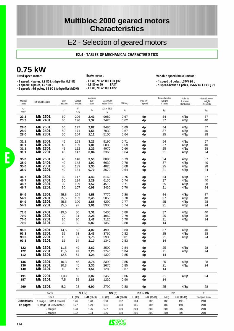
0.75 kW
E
114
23,3 Mb 2501 60 206 2,43 9980 0,67 4p 54 4/8p 5723,3 Mb 2401 60 190 1,32 7420 0,62 4p 37 4/8p 40
28,0 Mb 2501 50 177 2,87 9480 0,69 4p 54 4/8p 5728,0 Mb 2401 50 171 1,56 7030 0,67 4p 37 4/8p 4028,0 Mb 2301 50 164 1,11 5100 0,64 4p 25 4/8p 28
31,1 Mb 2501 45 163 3,23 9190 0,71 4p 54 4/8p 5731,1 Mb 2401 45 159 1,81 6830 0,69 4p 37 4/8p 4031,1 Mb 2301 45 152 1,23 4970 0,66 4p 25 4/8p 2831,1 Mb 2201 45 147 0,84 3360 0,64 4p 21 4/8p 24
35,0 Mb 2501 40 148 3,53 8880 0,73 4p 54 4/8p 5735,0 Mb 2401 40 143 1,92 6630 0,70 4p 37 4/8p 4035,0 Mb 2301 40 139 1,35 4820 0,68 4p 25 4/8p 2835,0 Mb 2201 40 131 0,79 3670 0,64 4p 21 4/8p 24
46,7 Mb 2501 30 117 4,43 8160 0,76 4p 54 4/8p 5746,7 Mb 2401 30 114 2,29 6130 0,74 4p 37 4/8p 4046,7 Mb 2301 30 109 1,57 4510 0,71 4p 25 4/8p 2846,7 Mb 2201 30 107 0,98 3430 0,70 4p 21 4/8p 24
54,9 Mb 2501 25,5 104 4,58 7770 0,80 4p 54 4/8p 5754,9 Mb 2401 25,5 102 2,45 5850 0,78 4p 37 4/8p 4054,9 Mb 2301 25,5 100 1,68 4290 0,77 4p 25 4/8p 2854,9 Mb 2201 25,5 97 1,01 3300 0,74 4p 21 4/8p 24
71,8 Mb 2401 19,5 80 3,31 5430 0,80 4p 37 4/8p 4070,0 Mb 2301 20 81 2,28 4050 0,79 4p 25 4/8p 2870,0 Mb 2201 20 80 1,47 3120 0,78 4p 21 4/8p 2470,0 Mb 3101 20 82 0,82 1350 0,80 4p 14
96,6 Mb 2401 14,5 62 4,02 4990 0,83 4p 37 4/8p 4093,3 Mb 2301 15 63 2,43 3750 0,82 4p 25 4/8p 2893,3 Mb 2201 15 62 1,75 2930 0,81 4p 21 4/8p 2493,3 Mb 3101 15 64 1,10 1340 0,83 4p 14
122 Mb 2301 11,5 49 3,62 3500 0,84 4p 25 4/8p 28122 Mb 2201 11,5 49 2,23 2740 0,84 4p 21 4/8p 24112 Mb 3101 12,5 54 1,24 1320 0,85 4p 14
136 Mb 2301 10,3 45 3,74 3390 0,85 4p 25 4/8p 28136 Mb 2201 10,3 45 2,30 2670 0,85 4p 21 4/8p 24140 Mb 3101 10 45 1,51 1280 0,87 4p 14
191 Mb 2201 7,33 32 3,02 2450 0,86 4p 21 4/8p 24187 Mb 3101 7,5 35 1,86 1230 0,90 4p 14
269 Mb 2301 5,2 23 6,90 2790 0,88 4p 25 4/8p 28
Form NU (N) NS (S) BS or BN BD RShaft H (C) L-R (G-D) H (C) L-R (G-D) H (C) L-R (G-D) H (C) L-R (G-D) Torque arm
Dimensions 1 stage U (B14 motor) 176 178 180 182 184 186 188 190 210on pages: 1 stage U (B5 motor) 177 179 181 183 185 187 189 191 210
2 stages 193 195 197 199 201 203 205 207 2103 stages 192 194 196 198 200 202 204 206 210
Multibloc 2000 geared motorsCharacteristics
E2 - Selection of geared motors
E2.4 - TABLES OF MECHANICAL CHARACTERISTICS
Fixed speed motor :
- 1 speed : 4 poles, LS 80 L (adapted for Mb3101)- 1 speed : 8 poles, LS 100 L- 2 speeds : 4/8 poles, LS 90 L (adapted for Mb2201)
Variable speed (brake) motor :
- 1 speed : 4 poles, LSMV 80 L- 1 speed-brake : 4 poles, LSMV 80 L FCR J01
Brake motor :
- LS 80, 90 or 100 FCR J02- LS 80 or 90 FAST- LS 80, 90 or 100 FAP2
Outputspeed
Exactreduction
Outputtorque
Maximumdutyfactor
Maximumradial force Efficiency
Polarity1 speed
Geared motorweight1 speed
Polarity2 speedsDahlander
Geared motorweight
2 speeds
nSmin-1 i
MN.m
KPFR at EB/2
Nη kg kg
Mb gearbox size
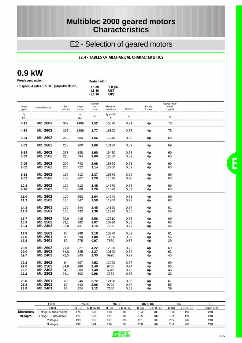
0.9 kW
E
115
4,11 Mb 2603 347 1486 1,52 16570 0,71 4p 78
4,64 Mb 2603 307 1389 1,77 16100 0,75 4p 78
5,24 Mb 2602 272 984 1,56 17240 0,60 4p 69
5,63 Mb 2602 253 900 1,66 17130 0,59 4p 69
6,54 Mb 2602 218 828 1,90 16450 0,63 4p 696,39 Mb 2502 223 794 1,06 12850 0,59 4p 63
7,05 Mb 2602 202 743 2,06 16360 0,61 4p 697,02 Mb 2502 203 722 1,14 12700 0,59 4p 63
9,13 Mb 2602 156 612 2,37 15370 0,65 4p 699,02 Mb 2502 158 667 1,20 11670 0,70 4p 63
10,3 Mb 2602 139 612 2,45 14670 0,73 4p 699,76 Mb 2502 146 608 1,29 11590 0,69 4p 63
11,0 Mb 2602 129 552 2,64 14540 0,71 4p 6911,3 Mb 2502 126 547 1,58 11200 0,72 4p 63
14,3 Mb 2601 100 344 2,45 14190 0,57 4p 6114,3 Mb 2501 100 332 1,38 11290 0,55 4p 56
15,7 Mb 2602 90,6 415 3,58 13310 0,76 4p 6915,3 Mb 2502 93,1 382 2,07 10720 0,68 4p 6315,4 Mb 2403 92,8 431 1,15 7160 0,77 4p 45
17,8 Mb 2601 80 299 3,18 13270 0,62 4p 6117,8 Mb 2501 80 290 1,80 10580 0,60 4p 5617,8 Mb 2401 80 275 0,97 7680 0,57 4p 39
20,0 Mb 2602 71,3 327 4,22 12580 0,76 4p 6919,0 Mb 2502 74,8 325 2,27 10120 0,72 4p 6319,7 Mb 2403 72,5 345 1,35 6920 0,79 4p 45
22,3 Mb 2602 64 297 4,52 12220 0,77 4p 6922,0 Mb 2502 64,8 289 2,46 9760 0,74 4p 6322,2 Mb 2403 64,1 302 1,48 6840 0,78 4p 4522,2 Mb 2303 64,1 302 0,96 2770 0,78 4p 33
23,8 Mb 2601 60 246 3,72 12190 0,68 4p 6123,8 Mb 2501 60 242 2,06 9720 0,67 4p 5623,8 Mb 2401 60 224 1,12 7150 0,62 4p 39
Form NU (N) NS (S) BS or BN BD RShaft H (C) L-R (G-D) H (C) L-R (G-D) H (C) L-R (G-D) H (C) L-R (G-D) Torque arm
Dimensions 1 stage U (B14 motor) 176 178 180 182 184 186 188 190 210on pages: 1 stage U (B5 motor) 177 179 181 183 185 187 189 191 210
2 stages 193 195 197 199 201 203 205 207 2103 stages 192 194 196 198 200 202 204 206 210
Multibloc 2000 geared motorsCharacteristics
E2 - Selection of geared motors
E2.4 - TABLES OF MECHANICAL CHARACTERISTICS
Fixed speed motor :
- 1 speed, 4 poles : LS 80 L (adapted for Mb3101)Brake motor :
- LS 80 FCR J02- LS 80 FAST- LS 80 FAP2
Outputspeed
Exactreduction
Outputtorque
Maximumdutyfactor
Maximumradial force Efficiency
Polarity1 speed
Geared motorweight1 speed
nSmin-1 i
MN.m
KPFR at EB/2
Nη kg
Mb gearbox size
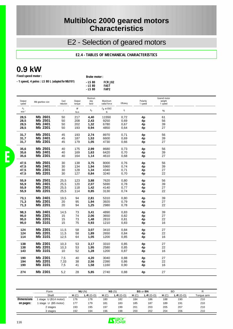
Form NU (N) NS (S) BS or BN BD RShaft H (C) L-R (G-D) H (C) L-R (G-D) H (C) L-R (G-D) H (C) L-R (G-D) Torque arm
Dimensions 1 stage U (B14 motor) 176 178 180 182 184 186 188 190 210on pages: 1 stage U (B5 motor) 177 179 181 183 185 187 189 191 210
2 stages 193 195 197 199 201 203 205 207 2103 stages 192 194 196 198 200 202 204 206 210
0.9 kW
E
116
28,5 Mb 2601 50 217 4,40 11550 0,72 4p 6128,5 Mb 2501 50 208 2,43 9250 0,69 4p 5628,5 Mb 2401 50 202 1,32 6780 0,67 4p 3928,5 Mb 2301 50 193 0,94 4850 0,64 4p 27
31,7 Mb 2501 45 193 2,74 8970 0,71 4p 5631,7 Mb 2401 45 187 1,53 6600 0,69 4p 3931,7 Mb 2301 45 179 1,05 4730 0,66 4p 27
35,6 Mb 2501 40 175 2,99 8680 0,73 4p 5635,6 Mb 2401 40 169 1,63 6420 0,70 4p 3935,6 Mb 2301 40 164 1,14 4610 0,68 4p 27
47,5 Mb 2501 30 138 3,75 8000 0,76 4p 5647,5 Mb 2401 30 134 1,94 5960 0,74 4p 3947,5 Mb 2301 30 128 1,34 4340 0,71 4p 2747,5 Mb 2201 30 127 0,84 3240 0,70 4p 22
55,9 Mb 2501 25,5 123 3,88 7620 0,80 4p 5655,9 Mb 2401 25,5 120 2,07 5690 0,78 4p 3955,9 Mb 2301 25,5 118 1,42 4140 0,77 4p 2755,9 Mb 2201 25,5 114 0,85 3130 0,74 4p 22
73,1 Mb 2401 19,5 94 2,81 5310 0,80 4p 3971,3 Mb 2301 20 95 1,94 3920 0,79 4p 2771,3 Mb 2201 20 94 1,25 2980 0,78 4p 22
98,3 Mb 2401 14,5 73 3,41 4890 0,83 4p 3995,0 Mb 2301 15 74 2,06 3650 0,82 4p 2795,0 Mb 2201 15 73 1,48 2810 0,81 4p 2295,0 Mb 3101 15 75 0,93 1210 0,83 4p 16
124 Mb 2301 11,5 58 3,07 3410 0,84 4p 27124 Mb 2201 11,5 58 1,89 2650 0,84 4p 22114 Mb 3101 12,5 64 1,05 1200 0,85 4p 16
138 Mb 2301 10,3 53 3,17 3310 0,85 4p 27138 Mb 2201 10,3 53 1,95 2580 0,85 4p 22143 Mb 3101 10 52 1,28 1200 0,87 4p 16
190 Mb 2301 7,5 40 4,20 3040 0,88 4p 27194 Mb 2201 7,33 38 2,56 2390 0,86 4p 22190 Mb 3101 7,5 41 1,58 1160 0,90 4p 16
274 Mb 2301 5,2 28 5,85 2740 0,88 4p 27
Multibloc 2000 geared motorsCharacteristics
E2 - Selection of geared motors
E2.4 - TABLES OF MECHANICAL CHARACTERISTICS
Fixed speed motor :
- 1 speed, 4 poles : LS 80 L (adapted for Mb3101)Brake motor :
- LS 80 FCR J02- LS 80 FAST- LS 80 FAP2
Outputspeed
Exactreduction
Outputtorque
Maximumdutyfactor
Maximumradial force Efficiency
Polarity1 speed
Geared motorweight1 speed
nSmin-1 i
MN.m
KPFR at EB/2
Nη kg
Mb gearbox size
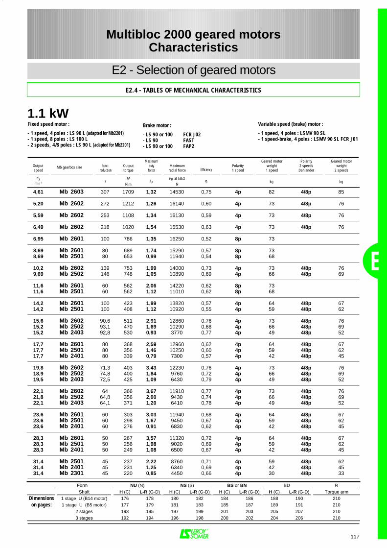
1.1 kW
E
117
4,61 Mb 2603 307 1709 1,32 14530 0,75 4p 82 4/8p 85
5,20 Mb 2602 272 1212 1,26 16140 0,60 4p 73 4/8p 76
5,59 Mb 2602 253 1108 1,34 16130 0,59 4p 73 4/8p 76
6,49 Mb 2602 218 1020 1,54 15530 0,63 4p 73 4/8p 76
6,95 Mb 2601 100 786 1,35 16250 0,52 8p 73
8,69 Mb 2601 80 689 1,74 15290 0,57 8p 738,69 Mb 2501 80 653 0,99 11940 0,54 8p 68
10,2 Mb 2602 139 753 1,99 14000 0,73 4p 73 4/8p 769,69 Mb 2502 146 748 1,05 10890 0,69 4p 66 4/8p 69
11,6 Mb 2601 60 562 2,06 14220 0,62 8p 7311,6 Mb 2501 60 562 1,12 11010 0,62 8p 68
14,2 Mb 2601 100 423 1,99 13820 0,57 4p 64 4/8p 6714,2 Mb 2501 100 408 1,12 10920 0,55 4p 59 4/8p 62
15,6 Mb 2602 90,6 511 2,91 12860 0,76 4p 73 4/8p 7615,2 Mb 2502 93,1 470 1,69 10290 0,68 4p 66 4/8p 6915,2 Mb 2403 92,8 530 0,93 3770 0,77 4p 49 4/8p 52
17,7 Mb 2601 80 368 2,59 12960 0,62 4p 64 4/8p 6717,7 Mb 2501 80 356 1,46 10250 0,60 4p 59 4/8p 6217,7 Mb 2401 80 339 0,79 7300 0,57 4p 42 4/8p 45
19,8 Mb 2602 71,3 403 3,43 12230 0,76 4p 73 4/8p 7618,9 Mb 2502 74,8 400 1,84 9760 0,72 4p 66 4/8p 6919,5 Mb 2403 72,5 425 1,09 6430 0,79 4p 49 4/8p 52
22,1 Mb 2602 64 366 3,67 11910 0,77 4p 73 4/8p 7621,8 Mb 2502 64,8 356 2,00 9430 0,74 4p 66 4/8p 6922,1 Mb 2403 64,1 371 1,20 6410 0,78 4p 49 4/8p 52
23,6 Mb 2601 60 303 3,03 11940 0,68 4p 64 4/8p 6723,6 Mb 2501 60 298 1,67 9450 0,67 4p 59 4/8p 6223,6 Mb 2401 60 276 0,91 6830 0,62 4p 42 4/8p 45
28,3 Mb 2601 50 267 3,57 11320 0,72 4p 64 4/8p 6728,3 Mb 2501 50 256 1,98 9020 0,69 4p 59 4/8p 6228,3 Mb 2401 50 249 1,08 6500 0,67 4p 42 4/8p 45
31,4 Mb 2501 45 237 2,22 8760 0,71 4p 59 4/8p 6231,4 Mb 2401 45 231 1,25 6340 0,69 4p 42 4/8p 4531,4 Mb 2301 45 220 0,85 4450 0,66 4p 30 4/8p 33
Form NU (N) NS (S) BS or BN BD RShaft H (C) L-R (G-D) H (C) L-R (G-D) H (C) L-R (G-D) H (C) L-R (G-D) Torque arm
Dimensions 1 stage U (B14 motor) 176 178 180 182 184 186 188 190 210on pages: 1 stage U (B5 motor) 177 179 181 183 185 187 189 191 210
2 stages 193 195 197 199 201 203 205 207 2103 stages 192 194 196 198 200 202 204 206 210
Multibloc 2000 geared motorsCharacteristics
E2 - Selection of geared motors
E2.4 - TABLES OF MECHANICAL CHARACTERISTICS
Fixed speed motor :
- 1 speed, 4 poles : LS 90 L (adapted for Mb2201)- 1 speed, 8 poles : LS 100 L- 2 speeds, 4/8 poles : LS 90 L (adapted for Mb2201)
Variable speed (brake) motor :
- 1 speed, 4 poles : LSMV 90 SL- 1 speed-brake, 4 poles : LSMV 90 SL FCR J01
Brake motor :
- LS 90 or 100 FCR J02- LS 90 FAST- LS 90 or 100 FAP2
Output speed
Exact reduction
Outputtorque
Maximumdutyfactor
Maximumradial force Efficiency
Polarity1 speed
Geared motorweight1 speed
Polarity2 speedsDahlander
Geared motorweight
2 speeds
nSmin-1 i
MN.m
KPFR at EB/2
Nη kg kg
Mb gearbox size
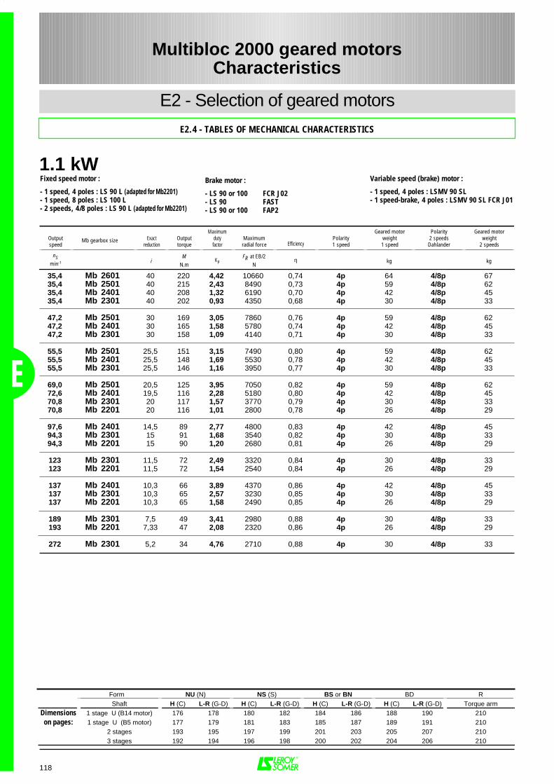
1.1 kW
E
118
35,4 Mb 2601 40 220 4,42 10660 0,74 4p 64 4/8p 6735,4 Mb 2501 40 215 2,43 8490 0,73 4p 59 4/8p 6235,4 Mb 2401 40 208 1,32 6190 0,70 4p 42 4/8p 4535,4 Mb 2301 40 202 0,93 4350 0,68 4p 30 4/8p 33
47,2 Mb 2501 30 169 3,05 7860 0,76 4p 59 4/8p 6247,2 Mb 2401 30 165 1,58 5780 0,74 4p 42 4/8p 4547,2 Mb 2301 30 158 1,09 4140 0,71 4p 30 4/8p 33
55,5 Mb 2501 25,5 151 3,15 7490 0,80 4p 59 4/8p 6255,5 Mb 2401 25,5 148 1,69 5530 0,78 4p 42 4/8p 4555,5 Mb 2301 25,5 146 1,16 3950 0,77 4p 30 4/8p 33
69,0 Mb 2501 20,5 125 3,95 7050 0,82 4p 59 4/8p 6272,6 Mb 2401 19,5 116 2,28 5180 0,80 4p 42 4/8p 4570,8 Mb 2301 20 117 1,57 3770 0,79 4p 30 4/8p 3370,8 Mb 2201 20 116 1,01 2800 0,78 4p 26 4/8p 29
97,6 Mb 2401 14,5 89 2,77 4800 0,83 4p 42 4/8p 4594,3 Mb 2301 15 91 1,68 3540 0,82 4p 30 4/8p 3394,3 Mb 2201 15 90 1,20 2680 0,81 4p 26 4/8p 29
123 Mb 2301 11,5 72 2,49 3320 0,84 4p 30 4/8p 33123 Mb 2201 11,5 72 1,54 2540 0,84 4p 26 4/8p 29
137 Mb 2401 10,3 66 3,89 4370 0,86 4p 42 4/8p 45137 Mb 2301 10,3 65 2,57 3230 0,85 4p 30 4/8p 33137 Mb 2201 10,3 65 1,58 2490 0,85 4p 26 4/8p 29
189 Mb 2301 7,5 49 3,41 2980 0,88 4p 30 4/8p 33193 Mb 2201 7,33 47 2,08 2320 0,86 4p 26 4/8p 29
272 Mb 2301 5,2 34 4,76 2710 0,88 4p 30 4/8p 33
Multibloc 2000 geared motorsCharacteristics
E2 - Selection of geared motors
E2.4 - TABLES OF MECHANICAL CHARACTERISTICS
Fixed speed motor :
- 1 speed, 4 poles : LS 90 L (adapted for Mb2201)- 1 speed, 8 poles : LS 100 L- 2 speeds, 4/8 poles : LS 90 L (adapted for Mb2201)
Variable speed (brake) motor :
- 1 speed, 4 poles : LSMV 90 SL- 1 speed-brake, 4 poles : LSMV 90 SL FCR J01
Brake motor :
- LS 90 or 100 FCR J02- LS 90 FAST- LS 90 or 100 FAP2
Outputspeed
Exactreduction
Outputtorque
Maximumdutyfactor
Maximumradial force Efficiency
Polarity1 speed
Geared motorweight1 speed
Polarity2 speedsDahlander
Geared motorweight
2 speeds
nSmin-1 i
MN.m
KPFR at EB/2
Nη kg kg
Mb gearbox size
Form NU (N) NS (S) BS or BN BD RShaft H (C) L-R (G-D) H (C) L-R (G-D) H (C) L-R (G-D) H (C) L-R (G-D) Torque arm
Dimensions 1 stage U (B14 motor) 176 178 180 182 184 186 188 190 210on pages: 1 stage U (B5 motor) 177 179 181 183 185 187 189 191 210
2 stages 193 195 197 199 201 203 205 207 2103 stages 192 194 196 198 200 202 204 206 210
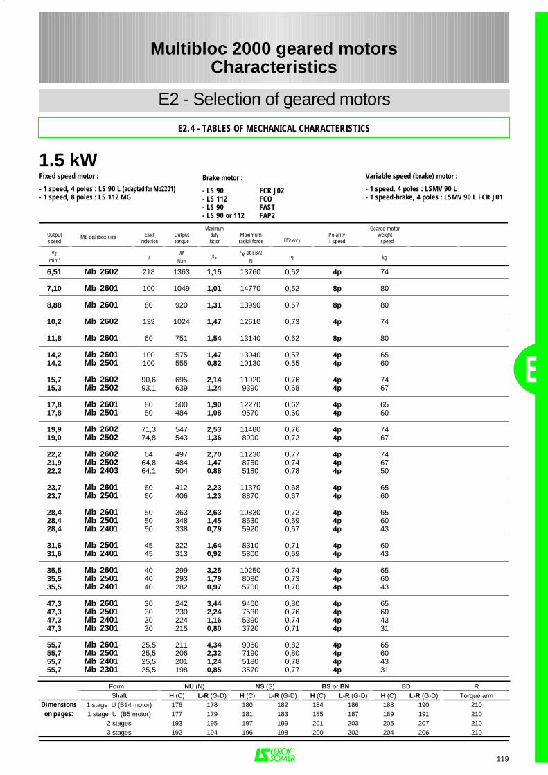
1.5 kW
E
119
6,51 Mb 2602 218 1363 1,15 13760 0,62 4p 74
7,10 Mb 2601 100 1049 1,01 14770 0,52 8p 80
8,88 Mb 2601 80 920 1,31 13990 0,57 8p 80
10,2 Mb 2602 139 1024 1,47 12610 0,73 4p 74
11,8 Mb 2601 60 751 1,54 13140 0,62 8p 80
14,2 Mb 2601 100 575 1,47 13040 0,57 4p 6514,2 Mb 2501 100 555 0,82 10130 0,55 4p 60
15,7 Mb 2602 90,6 695 2,14 11920 0,76 4p 7415,3 Mb 2502 93,1 639 1,24 9390 0,68 4p 67
17,8 Mb 2601 80 500 1,90 12270 0,62 4p 6517,8 Mb 2501 80 484 1,08 9570 0,60 4p 60
19,9 Mb 2602 71,3 547 2,53 11480 0,76 4p 7419,0 Mb 2502 74,8 543 1,36 8990 0,72 4p 67
22,2 Mb 2602 64 497 2,70 11230 0,77 4p 7421,9 Mb 2502 64,8 484 1,47 8750 0,74 4p 6722,2 Mb 2403 64,1 504 0,88 5180 0,78 4p 50
23,7 Mb 2601 60 412 2,23 11370 0,68 4p 6523,7 Mb 2501 60 406 1,23 8870 0,67 4p 60
28,4 Mb 2601 50 363 2,63 10830 0,72 4p 6528,4 Mb 2501 50 348 1,45 8530 0,69 4p 6028,4 Mb 2401 50 338 0,79 5920 0,67 4p 43
31,6 Mb 2501 45 322 1,64 8310 0,71 4p 6031,6 Mb 2401 45 313 0,92 5800 0,69 4p 43
35,5 Mb 2601 40 299 3,25 10250 0,74 4p 6535,5 Mb 2501 40 293 1,79 8080 0,73 4p 6035,5 Mb 2401 40 282 0,97 5700 0,70 4p 43
47,3 Mb 2601 30 242 3,44 9460 0,80 4p 6547,3 Mb 2501 30 230 2,24 7530 0,76 4p 6047,3 Mb 2401 30 224 1,16 5390 0,74 4p 4347,3 Mb 2301 30 215 0,80 3720 0,71 4p 31
55,7 Mb 2601 25,5 211 4,34 9060 0,82 4p 6555,7 Mb 2501 25,5 206 2,32 7190 0,80 4p 6055,7 Mb 2401 25,5 201 1,24 5180 0,78 4p 4355,7 Mb 2301 25,5 198 0,85 3570 0,77 4p 31
Form NU (N) NS (S) BS or BN BD RShaft H (C) L-R (G-D) H (C) L-R (G-D) H (C) L-R (G-D) H (C) L-R (G-D) Torque arm
Dimensions 1 stage U (B14 motor) 176 178 180 182 184 186 188 190 210on pages: 1 stage U (B5 motor) 177 179 181 183 185 187 189 191 210
2 stages 193 195 197 199 201 203 205 207 2103 stages 192 194 196 198 200 202 204 206 210
Multibloc 2000 geared motorsCharacteristics
E2 - Selection of geared motors
E2.4 - TABLES OF MECHANICAL CHARACTERISTICS
Fixed speed motor :
- 1 speed, 4 poles : LS 90 L (adapted for Mb2201)- 1 speed, 8 poles : LS 112 MG
Variable speed (brake) motor :
- 1 speed, 4 poles : LSMV 90 L- 1 speed-brake, 4 poles : LSMV 90 L FCR J01
Brake motor :
- LS 90 FCR J02- LS 112 FCO- LS 90 FAST- LS 90 or 112 FAP2
Outputspeed
Exactreduction
Outputtorque
Maximumdutyfactor
Maximumradial force Efficiency
Polarity1 speed
Geared motorweight1 speed
nSmin-1 i
MN.m
KPFR at EB/2
Nη kg
Mb gearbox size
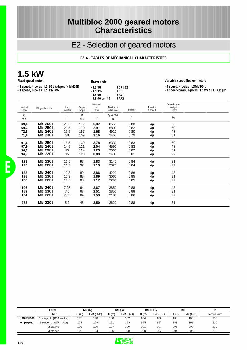
1.5 kW
E
120
69,3 Mb 2601 20,5 172 5,37 8550 0,83 4p 6569,3 Mb 2501 20,5 170 2,91 6800 0,82 4p 6072,8 Mb 2401 19,5 157 1,68 4910 0,80 4p 4371,0 Mb 2301 20 159 1,16 3460 0,79 4p 31
91,6 Mb 2501 15,5 130 3,78 6330 0,83 4p 6097,9 Mb 2401 14,5 121 2,04 4590 0,83 4p 4394,7 Mb 2301 15 124 1,23 3300 0,82 4p 3194,7 Mb 2201 15 123 0,89 2400 0,81 4p 27
123 Mb 2301 11,5 97 1,83 3140 0,84 4p 31123 Mb 2201 11,5 97 1,13 2320 0,84 4p 27
138 Mb 2401 10,3 89 2,86 4220 0,86 4p 43138 Mb 2301 10,3 88 1,89 3060 0,85 4p 31138 Mb 2201 10,3 88 1,17 2290 0,85 4p 27
196 Mb 2401 7,25 64 3,67 3850 0,88 4p 43189 Mb 2301 7,5 67 2,51 2850 0,88 4p 31194 Mb 2201 7,33 64 1,53 2180 0,86 4p 27
273 Mb 2301 5,2 46 3,50 2620 0,88 4p 31
Form NU (N) NS (S) BS or BN BD RShaft H (C) L-R (G-D) H (C) L-R (G-D) H (C) L-R (G-D) H (C) L-R (G-D) Torque arm
Dimensions 1 stage U (B14 motor) 176 178 180 182 184 186 188 190 210on pages: 1 stage U (B5 motor) 177 179 181 183 185 187 189 191 210
2 stages 193 195 197 199 201 203 205 207 2103 stages 192 194 196 198 200 202 204 206 210
Multibloc 2000 geared motorsCharacteristics
E2 - Selection of geared motors
E2.4 - TABLES OF MECHANICAL CHARACTERISTICS
Fixed speed motor :
- 1 speed, 4 poles : LS 90 L (adapted for Mb2201)- 1 speed, 8 poles : LS 112 MG
Variable speed (brake) motor :
- 1 speed, 4 poles : LSMV 90 L- 1 speed-brake, 4 poles : LSMV 90 L FCR J01
Brake motor :
- LS 90 FCR J02- LS 112 FCO- LS 90 FAST- LS 90 or 112 FAP2
Outputspeed
Exactreduction
Outputtorque
Maximumdutyfactor
Maximumradial force Efficiency
Polarity1 speed
Geared motorweight1 speed
nSmin-1 i
MN.m
KPFR at EB/2
Nη kg
Mb gearbox size
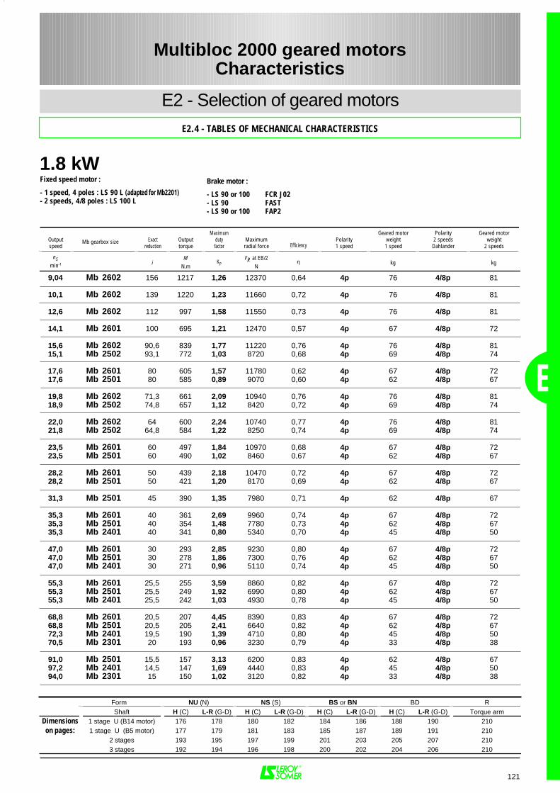
1.8 kW
E
121
9,04 Mb 2602 156 1217 1,26 12370 0,64 4p 76 4/8p 81
10,1 Mb 2602 139 1220 1,23 11660 0,72 4p 76 4/8p 81
12,6 Mb 2602 112 997 1,58 11550 0,73 4p 76 4/8p 81
14,1 Mb 2601 100 695 1,21 12470 0,57 4p 67 4/8p 72
15,6 Mb 2602 90,6 839 1,77 11220 0,76 4p 76 4/8p 8115,1 Mb 2502 93,1 772 1,03 8720 0,68 4p 69 4/8p 74
17,6 Mb 2601 80 605 1,57 11780 0,62 4p 67 4/8p 7217,6 Mb 2501 80 585 0,89 9070 0,60 4p 62 4/8p 67
19,8 Mb 2602 71,3 661 2,09 10940 0,76 4p 76 4/8p 8118,9 Mb 2502 74,8 657 1,12 8420 0,72 4p 69 4/8p 74
22,0 Mb 2602 64 600 2,24 10740 0,77 4p 76 4/8p 8121,8 Mb 2502 64,8 584 1,22 8250 0,74 4p 69 4/8p 74
23,5 Mb 2601 60 497 1,84 10970 0,68 4p 67 4/8p 7223,5 Mb 2501 60 490 1,02 8460 0,67 4p 62 4/8p 67
28,2 Mb 2601 50 439 2,18 10470 0,72 4p 67 4/8p 7228,2 Mb 2501 50 421 1,20 8170 0,69 4p 62 4/8p 67
31,3 Mb 2501 45 390 1,35 7980 0,71 4p 62 4/8p 67
35,3 Mb 2601 40 361 2,69 9960 0,74 4p 67 4/8p 7235,3 Mb 2501 40 354 1,48 7780 0,73 4p 62 4/8p 6735,3 Mb 2401 40 341 0,80 5340 0,70 4p 45 4/8p 50
47,0 Mb 2601 30 293 2,85 9230 0,80 4p 67 4/8p 7247,0 Mb 2501 30 278 1,86 7300 0,76 4p 62 4/8p 6747,0 Mb 2401 30 271 0,96 5110 0,74 4p 45 4/8p 50
55,3 Mb 2601 25,5 255 3,59 8860 0,82 4p 67 4/8p 7255,3 Mb 2501 25,5 249 1,92 6990 0,80 4p 62 4/8p 6755,3 Mb 2401 25,5 242 1,03 4930 0,78 4p 45 4/8p 50
68,8 Mb 2601 20,5 207 4,45 8390 0,83 4p 67 4/8p 7268,8 Mb 2501 20,5 205 2,41 6640 0,82 4p 62 4/8p 6772,3 Mb 2401 19,5 190 1,39 4710 0,80 4p 45 4/8p 5070,5 Mb 2301 20 193 0,96 3230 0,79 4p 33 4/8p 38
91,0 Mb 2501 15,5 157 3,13 6200 0,83 4p 62 4/8p 6797,2 Mb 2401 14,5 147 1,69 4440 0,83 4p 45 4/8p 5094,0 Mb 2301 15 150 1,02 3120 0,82 4p 33 4/8p 38
Form NU (N) NS (S) BS or BN BD RShaft H (C) L-R (G-D) H (C) L-R (G-D) H (C) L-R (G-D) H (C) L-R (G-D) Torque arm
Dimensions 1 stage U (B14 motor) 176 178 180 182 184 186 188 190 210on pages: 1 stage U (B5 motor) 177 179 181 183 185 187 189 191 210
2 stages 193 195 197 199 201 203 205 207 2103 stages 192 194 196 198 200 202 204 206 210
Multibloc 2000 geared motorsCharacteristics
E2 - Selection of geared motors
E2.4 - TABLES OF MECHANICAL CHARACTERISTICS
Fixed speed motor :
- 1 speed, 4 poles : LS 90 L (adapted for Mb2201)- 2 speeds, 4/8 poles : LS 100 L
Brake motor :
- LS 90 or 100 FCR J02- LS 90 FAST- LS 90 or 100 FAP2
Outputspeed
Exactreduction
Outputtorque
Maximumdutyfactor
Maximumradial force Efficiency
Polarity1 speed
Geared motorweight1 speed
Polarity2 speedsDahlander
Geared motorweight
2 speeds
nSmin-1 i
MN.m
KPFR at EB/2
Nη kg kg
Mb gearbox size
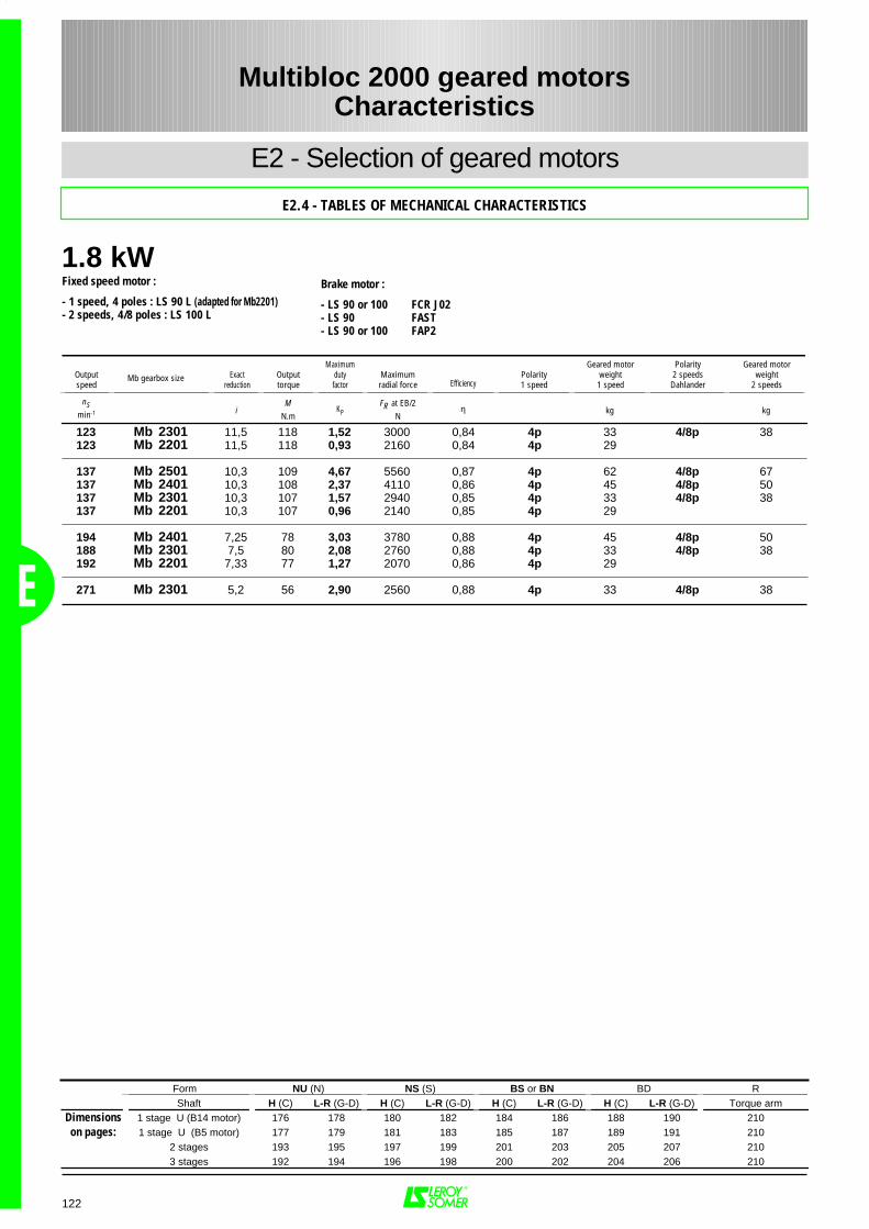
1.8 kW
E
122
123 Mb 2301 11,5 118 1,52 3000 0,84 4p 33 4/8p 38123 Mb 2201 11,5 118 0,93 2160 0,84 4p 29
137 Mb 2501 10,3 109 4,67 5560 0,87 4p 62 4/8p 67137 Mb 2401 10,3 108 2,37 4110 0,86 4p 45 4/8p 50137 Mb 2301 10,3 107 1,57 2940 0,85 4p 33 4/8p 38137 Mb 2201 10,3 107 0,96 2140 0,85 4p 29
194 Mb 2401 7,25 78 3,03 3780 0,88 4p 45 4/8p 50188 Mb 2301 7,5 80 2,08 2760 0,88 4p 33 4/8p 38192 Mb 2201 7,33 77 1,27 2070 0,86 4p 29
271 Mb 2301 5,2 56 2,90 2560 0,88 4p 33 4/8p 38
Form NU (N) NS (S) BS or BN BD RShaft H (C) L-R (G-D) H (C) L-R (G-D) H (C) L-R (G-D) H (C) L-R (G-D) Torque arm
Dimensions 1 stage U (B14 motor) 176 178 180 182 184 186 188 190 210on pages: 1 stage U (B5 motor) 177 179 181 183 185 187 189 191 210
2 stages 193 195 197 199 201 203 205 207 2103 stages 192 194 196 198 200 202 204 206 210
Multibloc 2000 geared motorsCharacteristics
E2 - Selection of geared motors
E2.4 - TABLES OF MECHANICAL CHARACTERISTICS
Fixed speed motor :
- 1 speed, 4 poles : LS 90 L (adapted for Mb2201)- 2 speeds, 4/8 poles : LS 100 L
Brake motor :
- LS 90 or 100 FCR J02- LS 90 FAST- LS 90 or 100 FAP2
Outputspeed
Exactreduction
Outputtorque
Maximumdutyfactor
Maximumradial force Efficiency
Polarity1 speed
Geared motorweight1 speed
Polarity2 speedsDahlander
Geared motorweight
2 speeds
nSmin-1 i
MN.m
KPFR at EB/2
Nη kg kg
Mb gearbox size
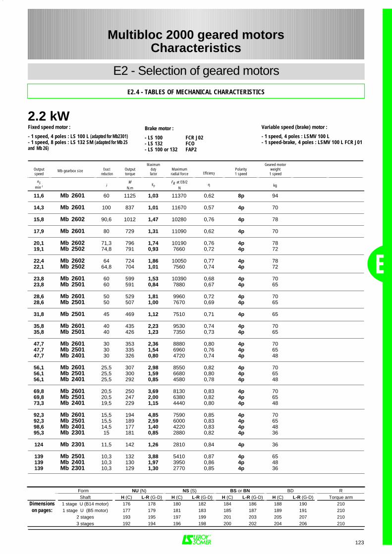
2.2 kW
E
123
11,6 Mb 2601 60 1125 1,03 11370 0,62 8p 94
14,3 Mb 2601 100 837 1,01 11670 0,57 4p 70
15,8 Mb 2602 90,6 1012 1,47 10280 0,76 4p 78
17,9 Mb 2601 80 729 1,31 11090 0,62 4p 70
20,1 Mb 2602 71,3 796 1,74 10190 0,76 4p 7819,1 Mb 2502 74,8 791 0,93 7660 0,72 4p 72
22,4 Mb 2602 64 724 1,86 10050 0,77 4p 7822,1 Mb 2502 64,8 704 1,01 7560 0,74 4p 72
23,8 Mb 2601 60 599 1,53 10390 0,68 4p 7023,8 Mb 2501 60 591 0,84 7880 0,67 4p 65
28,6 Mb 2601 50 529 1,81 9960 0,72 4p 7028,6 Mb 2501 50 507 1,00 7670 0,69 4p 65
31,8 Mb 2501 45 469 1,12 7510 0,71 4p 65
35,8 Mb 2601 40 435 2,23 9530 0,74 4p 7035,8 Mb 2501 40 426 1,23 7350 0,73 4p 65
47,7 Mb 2601 30 353 2,36 8880 0,80 4p 7047,7 Mb 2501 30 335 1,54 6960 0,76 4p 6547,7 Mb 2401 30 326 0,80 4720 0,74 4p 48
56,1 Mb 2601 25,5 307 2,98 8550 0,82 4p 7056,1 Mb 2501 25,5 300 1,59 6680 0,80 4p 6556,1 Mb 2401 25,5 292 0,85 4580 0,78 4p 48
69,8 Mb 2601 20,5 250 3,69 8130 0,83 4p 7069,8 Mb 2501 20,5 247 2,00 6380 0,82 4p 6573,3 Mb 2401 19,5 229 1,15 4440 0,80 4p 48
92,3 Mb 2601 15,5 194 4,85 7590 0,85 4p 7092,3 Mb 2501 15,5 189 2,59 6000 0,83 4p 6598,6 Mb 2401 14,5 177 1,40 4220 0,83 4p 4895,3 Mb 2301 15 181 0,85 2880 0,82 4p 36
124 Mb 2301 11,5 142 1,26 2810 0,84 4p 36
139 Mb 2501 10,3 132 3,88 5410 0,87 4p 65139 Mb 2401 10,3 130 1,97 3950 0,86 4p 48139 Mb 2301 10,3 129 1,30 2770 0,85 4p 36
Form NU (N) NS (S) BS or BN BD RShaft H (C) L-R (G-D) H (C) L-R (G-D) H (C) L-R (G-D) H (C) L-R (G-D) Torque arm
Dimensions 1 stage U (B14 motor) 176 178 180 182 184 186 188 190 210on pages: 1 stage U (B5 motor) 177 179 181 183 185 187 189 191 210
2 stages 193 195 197 199 201 203 205 207 2103 stages 192 194 196 198 200 202 204 206 210
Multibloc 2000 geared motorsCharacteristics
E2 - Selection of geared motors
E2.4 - TABLES OF MECHANICAL CHARACTERISTICS
Fixed speed motor :
- 1 speed, 4 poles : LS 100 L (adapted for Mb2301)- 1 speed, 8 poles : LS 132 SM (adapted for Mb 25and Mb 26)
Variable speed (brake) motor :
- 1 speed, 4 poles : LSMV 100 L- 1 speed-brake, 4 poles : LSMV 100 L FCR J01
Brake motor :
- LS 100 FCR J02- LS 132 FCO- LS 100 or 132 FAP2
Outputspeed
Exact reduction
Outputtorque
Maximumdutyfactor
Maximumradial force Efficiency
Polarity1 speed
Geared motorweight1 speed
nSmin-1 i
MN.m
KPFR at EB/2
Nη kg
Mb gearbox size
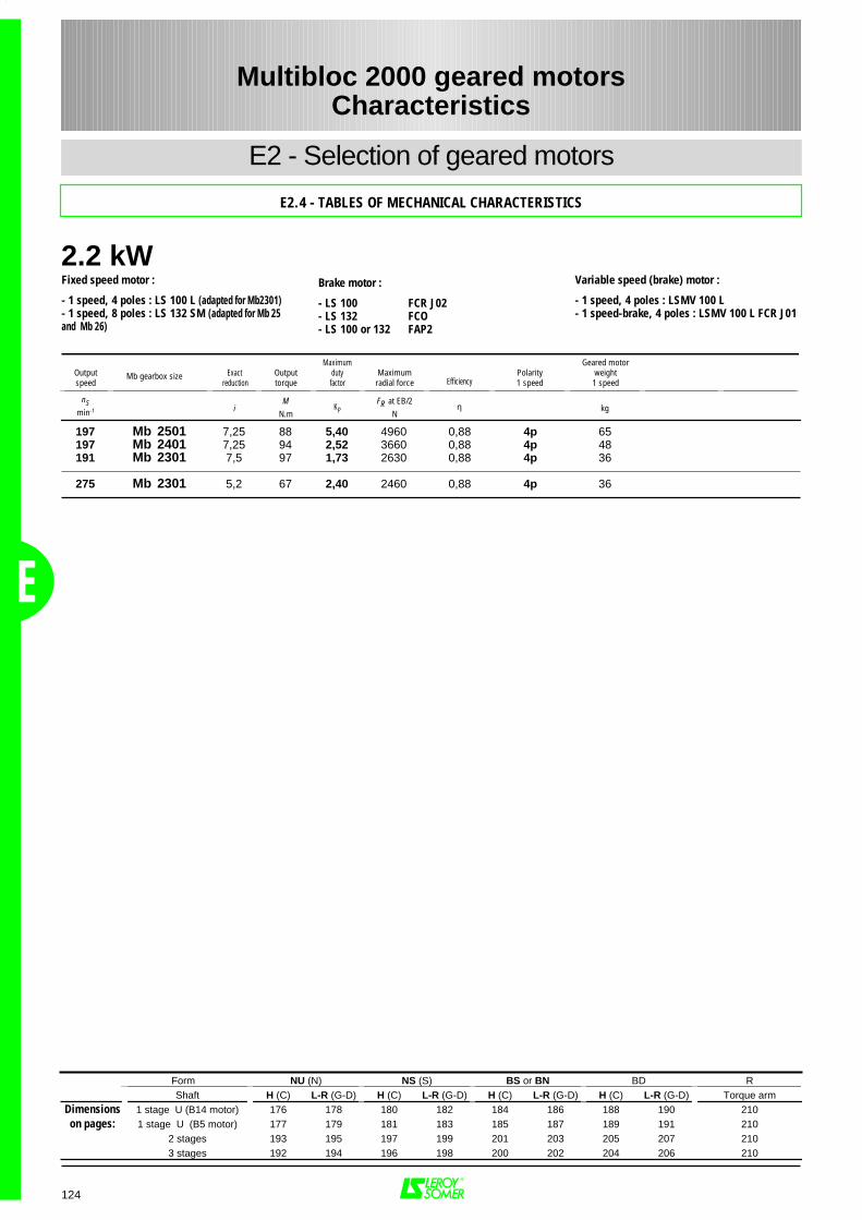
2.2 kW
E
124
197 Mb 2501 7,25 88 5,40 4960 0,88 4p 65197 Mb 2401 7,25 94 2,52 3660 0,88 4p 48191 Mb 2301 7,5 97 1,73 2630 0,88 4p 36
275 Mb 2301 5,2 67 2,40 2460 0,88 4p 36
Form NU (N) NS (S) BS or BN BD RShaft H (C) L-R (G-D) H (C) L-R (G-D) H (C) L-R (G-D) H (C) L-R (G-D) Torque arm
Dimensions 1 stage U (B14 motor) 176 178 180 182 184 186 188 190 210on pages: 1 stage U (B5 motor) 177 179 181 183 185 187 189 191 210
2 stages 193 195 197 199 201 203 205 207 2103 stages 192 194 196 198 200 202 204 206 210
Multibloc 2000 geared motorsCharacteristics
E2 - Selection of geared motors
E2.4 - TABLES OF MECHANICAL CHARACTERISTICS
Fixed speed motor :
- 1 speed, 4 poles : LS 100 L (adapted for Mb2301)- 1 speed, 8 poles : LS 132 SM (adapted for Mb 25and Mb 26)
Variable speed (brake) motor :
- 1 speed, 4 poles : LSMV 100 L- 1 speed-brake, 4 poles : LSMV 100 L FCR J01
Brake motor :
- LS 100 FCR J02- LS 132 FCO- LS 100 or 132 FAP2
Outputspeed
Exact reduction
Outputtorque
Maximumdutyfactor
Maximumradial force Efficiency
Polarity1 speed
Geared motorweight1 speed
nSmin-1 i
MN.m
KPFR at EB/2
Nη kg
Mb gearbox size
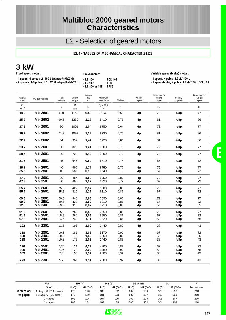
3 kW
E
125
14,2 Mb 2601 100 1150 0,80 10130 0,59 4p 72 4/8p 77
15,7 Mb 2602 90,6 1389 1,17 8410 0,76 4p 81 4/8p 86
17,8 Mb 2601 80 1001 1,04 9750 0,64 4p 72 4/8p 77
19,9 Mb 2602 71,3 1093 1,38 8730 0,77 4p 81 4/8p 86
22,2 Mb 2602 64 994 1,47 8720 0,80 4p 81 4/8p 86
23,7 Mb 2601 60 823 1,21 9300 0,71 4p 72 4/8p 77
28,4 Mb 2601 50 726 1,43 9000 0,75 4p 72 4/8p 77
31,6 Mb 2501 45 645 0,89 6610 0,74 4p 67 4/8p 72
35,5 Mb 2601 40 597 1,77 8750 0,77 4p 72 4/8p 7735,5 Mb 2501 40 585 0,98 6540 0,75 4p 67 4/8p 72
47,3 Mb 2601 30 484 1,88 8250 0,83 4p 72 4/8p 7747,3 Mb 2501 30 460 1,22 6320 0,79 4p 67 4/8p 72
55,7 Mb 2601 25,5 422 2,37 8000 0,85 4p 72 4/8p 7755,7 Mb 2501 25,5 412 1,27 6110 0,83 4p 67 4/8p 72
69,3 Mb 2601 20,5 343 2,93 7690 0,86 4p 72 4/8p 7769,3 Mb 2501 20,5 339 1,59 5910 0,85 4p 67 4/8p 7272,8 Mb 2401 19,5 315 0,92 3910 0,83 4p 50 4/8p 55
91,6 Mb 2601 15,5 266 3,86 7250 0,88 4p 72 4/8p 7791,6 Mb 2501 15,5 260 2,06 5650 0,86 4p 67 4/8p 7297,9 Mb 2401 14,5 243 1,11 3820 0,86 4p 50 4/8p 55
123 Mb 2301 11,5 195 1,00 2440 0,87 4p 38 4/8p 43
138 Mb 2501 10,3 181 3,08 5170 0,90 4p 67 4/8p 72138 Mb 2401 10,3 179 1,56 3650 0,89 4p 50 4/8p 55138 Mb 2301 10,3 177 1,03 2440 0,88 4p 38 4/8p 43
196 Mb 2501 7,25 121 4,29 4800 0,88 4p 67 4/8p 72196 Mb 2401 7,25 129 2,00 3450 0,92 4p 50 4/8p 55189 Mb 2301 7,5 133 1,37 2380 0,92 4p 38 4/8p 43
273 Mb 2301 5,2 92 1,91 2300 0,92 4p 38 4/8p 43
Form NU (N) NS (S) BS or BN BD RShaft H (C) L-R (G-D) H (C) L-R (G-D) H (C) L-R (G-D) H (C) L-R (G-D) Torque arm
Dimensions 1 stage U (B14 motor) 176 178 180 182 184 186 188 190 210on pages: 1 stage U (B5 motor) 177 179 181 183 185 187 189 191 210
2 stages 193 195 197 199 201 203 205 207 2103 stages 192 194 196 198 200 202 204 206 210
Multibloc 2000 geared motorsCharacteristics
E2 - Selection of geared motors
E2.4 - TABLES OF MECHANICAL CHARACTERISTICS
Fixed speed motor :
- 1 speed, 4 poles : LS 100 L (adapted for Mb2301)- 2 speeds, 4/8 poles : LS 112 M (adapted for Mb2301)
Variable speed (brake) motor :
- 1 speed, 4 poles : LSMV 100 L- 1 speed-brake, 4 poles : LSMV 100 L FCR J01
Brake motor :
- LS 100 FCR J02- LS 112 FCO- LS 100 or 112 FAP2
Outputspeed
Exact reduction
Outputtorque
Maximumdutyfactor
Maximumradial force Efficiency
Polarity1 speed
Geared motorweight1 speed
Polarity2 speeds
Geared motorweight
2 speeds
nSmin-1 i
MN.m
KPFR at EB/2
Nη kg kg
Mb gearbox size
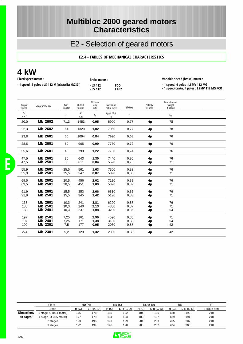
4 kW
E
126
20,0 Mb 2602 71,3 1453 0,95 6900 0,77 4p 78
22,3 Mb 2602 64 1320 1,02 7060 0,77 4p 78
23,8 Mb 2601 60 1094 0,84 7920 0,68 4p 76
28,5 Mb 2601 50 965 0,99 7780 0,72 4p 76
35,6 Mb 2601 40 793 1,22 7750 0,74 4p 76
47,5 Mb 2601 30 643 1,30 7440 0,80 4p 7647,5 Mb 2501 30 611 0,84 5520 0,76 4p 71
55,9 Mb 2601 25,5 561 1,63 7300 0,82 4p 7655,9 Mb 2501 25,5 547 0,87 5390 0,80 4p 71
69,5 Mb 2601 20,5 456 2,02 7120 0,83 4p 7669,5 Mb 2501 20,5 451 1,09 5320 0,82 4p 71
91,9 Mb 2601 15,5 353 2,66 6810 0,85 4p 7691,9 Mb 2501 15,5 345 1,42 5190 0,83 4p 71
138 Mb 2601 10,3 241 3,81 6290 0,87 4p 76138 Mb 2501 10,3 240 2,13 4850 0,87 4p 71138 Mb 2401 10,3 237 1,08 3280 0,86 4p 54
197 Mb 2501 7,25 161 2,96 4590 0,88 4p 71197 Mb 2401 7,25 171 1,38 3180 0,88 4p 54190 Mb 2301 7,5 177 0,95 2070 0,88 4p 42
274 Mb 2301 5,2 123 1,32 2080 0,88 4p 42
Form NU (N) NS (S) BS or BN BD RShaft H (C) L-R (G-D) H (C) L-R (G-D) H (C) L-R (G-D) H (C) L-R (G-D) Torque arm
Dimensions 1 stage U (B14 motor) 176 178 180 182 184 186 188 190 210on pages: 1 stage U (B5 motor) 177 179 181 183 185 187 189 191 210
2 stages 193 195 197 199 201 203 205 207 2103 stages 192 194 196 198 200 202 204 206 210
Multibloc 2000 geared motorsCharacteristics
E2 - Selection of geared motors
E2.4 - TABLES OF MECHANICAL CHARACTERISTICS
Fixed speed motor :
- 1 speed, 4 poles : LS 112 M (adapted for Mb2301)
Variable speed (brake) motor :
- 1 speed, 4 poles : LSMV 112 MG- 1 speed-brake, 4 poles : LSMV 112 MG FCO
Brake motor :
- LS 112 FCO- LS 112 FAP2
Outputspeed
Exact reduction
Outputtorque
Maximumdutyfactor
Maximumradial force Efficiency
Polarity1 speed
Geared motorweight1 speed
nSmin-1 i
MN.m
KPFR at EB/2
Nη kg
Mb gearbox size
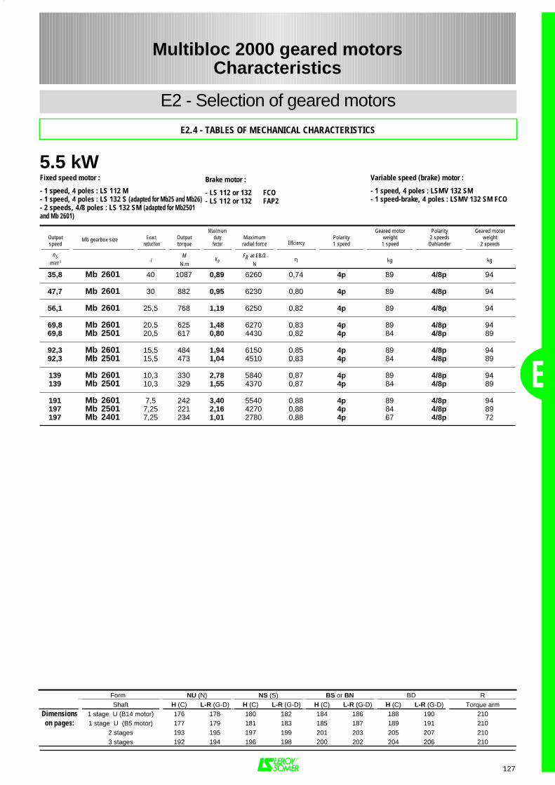
5.5 kW
E
127
35,8 Mb 2601 40 1087 0,89 6260 0,74 4p 89 4/8p 94
47,7 Mb 2601 30 882 0,95 6230 0,80 4p 89 4/8p 94
56,1 Mb 2601 25,5 768 1,19 6250 0,82 4p 89 4/8p 94
69,8 Mb 2601 20,5 625 1,48 6270 0,83 4p 89 4/8p 9469,8 Mb 2501 20,5 617 0,80 4430 0,82 4p 84 4/8p 89
92,3 Mb 2601 15,5 484 1,94 6150 0,85 4p 89 4/8p 9492,3 Mb 2501 15,5 473 1,04 4510 0,83 4p 84 4/8p 89
139 Mb 2601 10,3 330 2,78 5840 0,87 4p 89 4/8p 94139 Mb 2501 10,3 329 1,55 4370 0,87 4p 84 4/8p 89
191 Mb 2601 7,5 242 3,40 5540 0,88 4p 89 4/8p 94197 Mb 2501 7,25 221 2,16 4270 0,88 4p 84 4/8p 89197 Mb 2401 7,25 234 1,01 2780 0,88 4p 67 4/8p 72
Form NU (N) NS (S) BS or BN BD RShaft H (C) L-R (G-D) H (C) L-R (G-D) H (C) L-R (G-D) H (C) L-R (G-D) Torque arm
Dimensions 1 stage U (B14 motor) 176 178 180 182 184 186 188 190 210on pages: 1 stage U (B5 motor) 177 179 181 183 185 187 189 191 210
2 stages 193 195 197 199 201 203 205 207 2103 stages 192 194 196 198 200 202 204 206 210
Multibloc 2000 geared motorsCharacteristics
E2 - Selection of geared motors
E2.4 - TABLES OF MECHANICAL CHARACTERISTICS
Fixed speed motor :
- 1 speed, 4 poles : LS 112 M- 1 speed, 4 poles : LS 132 S (adapted for Mb25 and Mb26)- 2 speeds, 4/8 poles : LS 132 SM (adapted for Mb2501and Mb 2601)
Variable speed (brake) motor :
- 1 speed, 4 poles : LSMV 132 SM- 1 speed-brake, 4 poles : LSMV 132 SM FCO
Brake motor :
- LS 112 or 132 FCO- LS 112 or 132 FAP2
Outputspeed
Exact reduction
Outputtorque
Maximumdutyfactor
Maximumradial force Efficiency
Polarity1 speed
Geared motorweight1 speed
Polarity2 speedsDahlander
Geared motorweight
2 speeds
nSmin-1 i
MN.m
KPFR at EB/2
Nη kg kg
Mb gearbox size
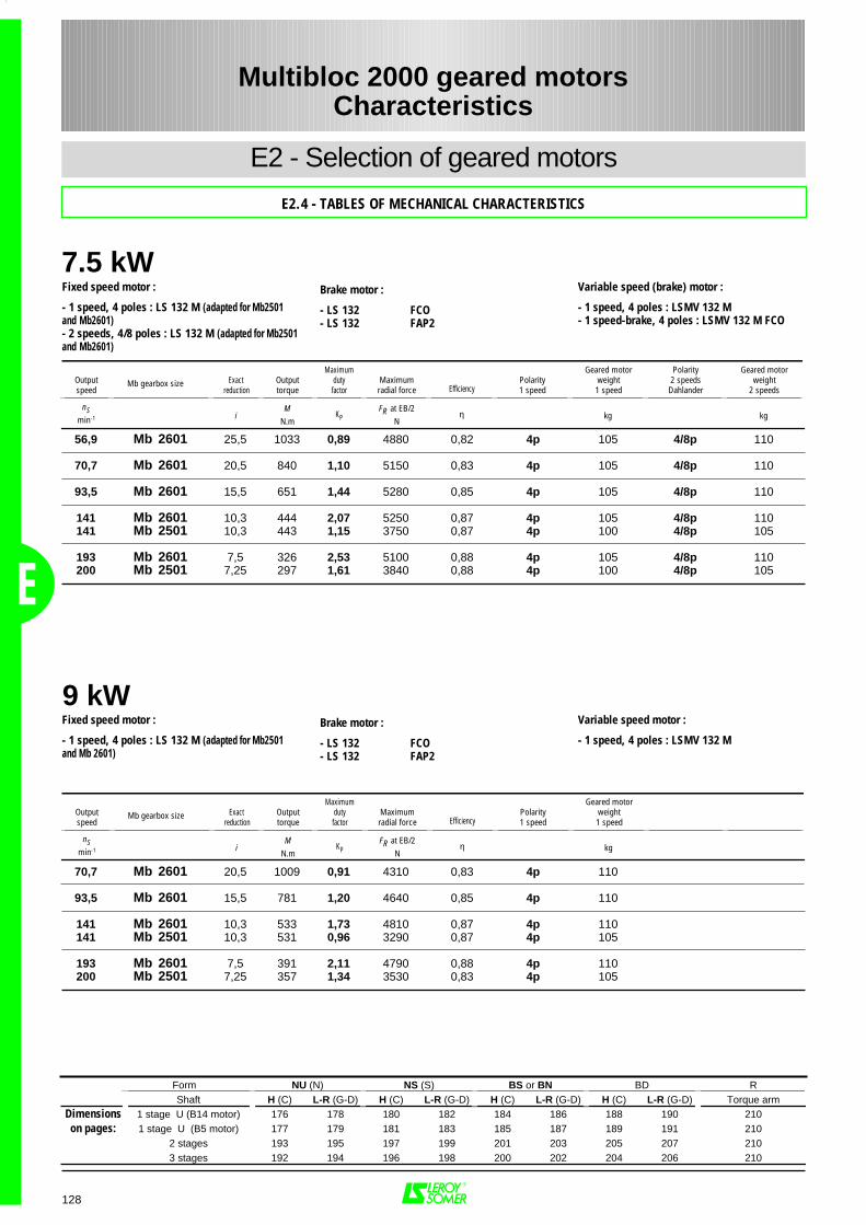
7.5 kW
E
128
56,9 Mb 2601 25,5 1033 0,89 4880 0,82 4p 105 4/8p 110
70,7 Mb 2601 20,5 840 1,10 5150 0,83 4p 105 4/8p 110
93,5 Mb 2601 15,5 651 1,44 5280 0,85 4p 105 4/8p 110
141 Mb 2601 10,3 444 2,07 5250 0,87 4p 105 4/8p 110141 Mb 2501 10,3 443 1,15 3750 0,87 4p 100 4/8p 105
193 Mb 2601 7,5 326 2,53 5100 0,88 4p 105 4/8p 110200 Mb 2501 7,25 297 1,61 3840 0,88 4p 100 4/8p 105
70,7 Mb 2601 20,5 1009 0,91 4310 0,83 4p 110
93,5 Mb 2601 15,5 781 1,20 4640 0,85 4p 110
141 Mb 2601 10,3 533 1,73 4810 0,87 4p 110141 Mb 2501 10,3 531 0,96 3290 0,87 4p 105
193 Mb 2601 7,5 391 2,11 4790 0,88 4p 110200 Mb 2501 7,25 357 1,34 3530 0,83 4p 105
Form NU (N) NS (S) BS or BN BD RShaft H (C) L-R (G-D) H (C) L-R (G-D) H (C) L-R (G-D) H (C) L-R (G-D) Torque arm
Dimensions 1 stage U (B14 motor) 176 178 180 182 184 186 188 190 210on pages: 1 stage U (B5 motor) 177 179 181 183 185 187 189 191 210
2 stages 193 195 197 199 201 203 205 207 2103 stages 192 194 196 198 200 202 204 206 210
Multibloc 2000 geared motorsCharacteristics
E2 - Selection of geared motors
E2.4 - TABLES OF MECHANICAL CHARACTERISTICS
9 kW
Fixed speed motor :
- 1 speed, 4 poles : LS 132 M (adapted for Mb2501and Mb2601)- 2 speeds, 4/8 poles : LS 132 M (adapted for Mb2501and Mb2601)
Variable speed (brake) motor :
- 1 speed, 4 poles : LSMV 132 M- 1 speed-brake, 4 poles : LSMV 132 M FCO
Brake motor :
- LS 132 FCO- LS 132 FAP2
Outputspeed
Exact reduction
Outputtorque
Maximumdutyfactor
Maximumradial force Efficiency
Polarity1 speed
Geared motorweight1 speed
Polarity2 speedsDahlander
Geared motorweight
2 speeds
nSmin-1 i
MN.m
KPFR at EB/2
Nη kg kg
Mb gearbox size
Fixed speed motor :
- 1 speed, 4 poles : LS 132 M (adapted for Mb2501and Mb 2601)
Variable speed motor :
- 1 speed, 4 poles : LSMV 132 MBrake motor :
- LS 132 FCO- LS 132 FAP2
Outputspeed
Exact reduction
Outputtorque
Maximumdutyfactor
Maximumradial force Efficiency
Polarity1 speed
Geared motorweight1 speed
nSmin-1 i
MN.m
KPFR at EB/2
Nη kg
Mb gearbox size
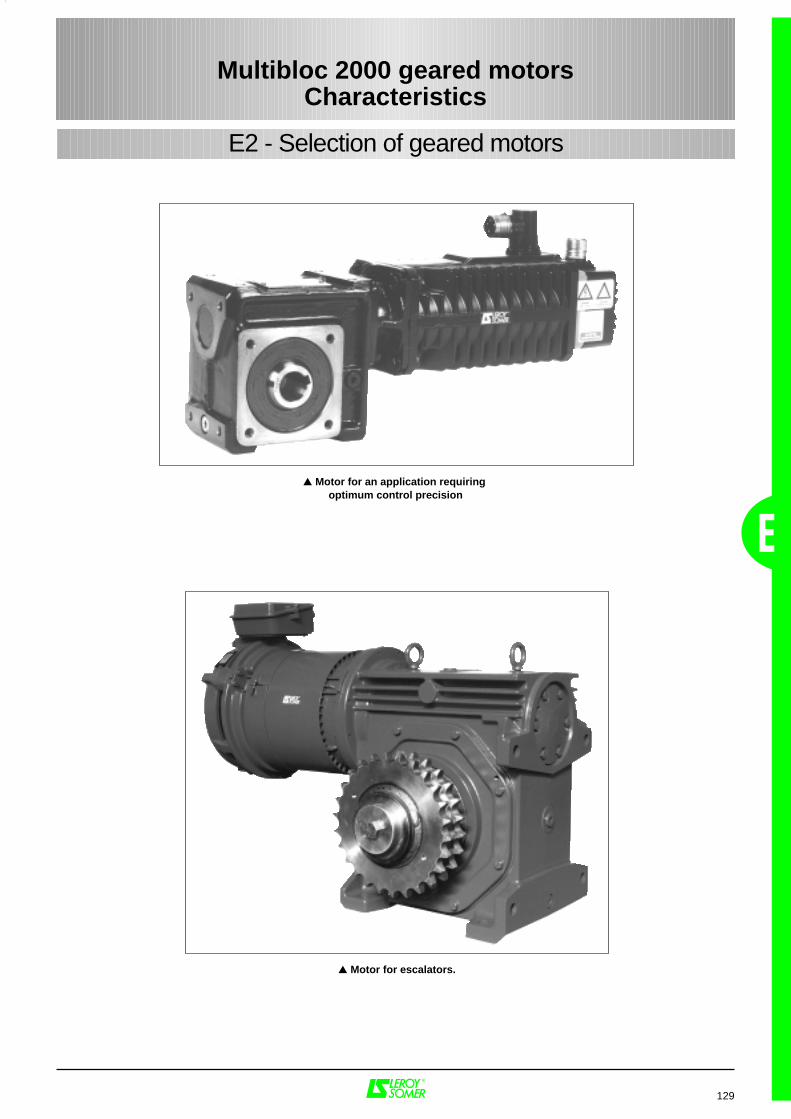
129
E
E2 - Selection of geared motors
Multibloc 2000 geared motorsCharacteristics
Motor for an application requiring optimum control precision
Motor for escalators.
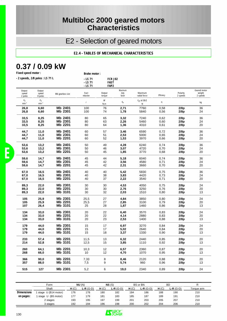
0.37 / 0.09 kW
E
130
26,8 6,60 Mb 2401 100 76 2,71 7760 0,58 2/8p 3626,8 6,60 Mb 2301 100 74 1,78 5840 0,56 2/8p 24
33,5 8,25 Mb 2401 80 65 3,32 7240 0,62 2/8p 3633,5 8,25 Mb 2301 80 63 2,26 5460 0,60 2/8p 2433,5 8,25 Mb 2201 80 64 1,36 4310 0,61 2/8p 20
44,7 11,0 Mb 2401 60 57 3,46 6590 0,72 2/8p 3644,7 11,0 Mb 2301 60 51 2,53 5000 0,65 2/8p 2444,7 11,0 Mb 2201 60 52 1,53 3970 0,66 2/8p 20
53,6 13,2 Mb 2401 50 49 4,28 6240 0,74 2/8p 3653,6 13,2 Mb 2301 50 46 3,07 4720 0,70 2/8p 2453,6 13,2 Mb 2201 50 45 1,85 3770 0,68 2/8p 20
59,6 14,7 Mb 2401 45 44 5,18 6040 0,74 2/8p 3659,6 14,7 Mb 2301 45 42 3,56 4580 0,71 2/8p 2459,6 14,7 Mb 2201 45 42 2,31 3660 0,70 2/8p 20
67,0 16,5 Mb 2401 40 40 5,42 5830 0,75 2/8p 3667,0 16,5 Mb 2301 40 38 3,83 4420 0,73 2/8p 2467,0 16,5 Mb 2201 40 37 2,22 3540 0,71 2/8p 20
89,3 22,0 Mb 2301 30 30 4,53 4050 0,75 2/8p 2489,3 22,0 Mb 2201 30 30 2,76 3250 0,76 2/8p 2089,3 22,0 Mb 3101 30 32 2,03 1510 0,80 2/8p 13
105 25,9 Mb 2301 25,5 27 4,84 3850 0,80 2/8p 24105 25,9 Mb 2201 25,5 27 2,85 3100 0,79 2/8p 20107 26,4 Mb 3101 25 28 1,87 1460 0,86 2/8p 13
134 33,0 Mb 2301 20 22 6,40 3570 0,83 2/8p 24134 33,0 Mb 2201 20 22 4,14 2880 0,83 2/8p 20134 33,0 Mb 3101 20 23 2,53 1400 0,88 2/8p 13
179 44,0 Mb 2301 15 17 6,97 3270 0,84 2/8p 24179 44,0 Mb 2201 15 17 5,02 2640 0,84 2/8p 20179 44,0 Mb 3101 15 18 3,37 1330 0,90 2/8p 13
233 57,4 Mb 2201 11,5 13 6,32 2440 0,85 2/8p 20214 52,8 Mb 3101 12,5 15 3,85 1110 0,92 2/8p 13
260 64,1 Mb 2201 10,3 12 6,57 2360 0,87 2/8p 20268 66,0 Mb 3101 10 12 4,70 1070 0,95 2/8p 13
366 90,0 Mb 2201 7,33 8 8,46 2120 0,88 2/8p 20357 88,0 Mb 3101 7,5 9 5,74 960 0,96 2/8p 13
515 127 Mb 2301 5,2 6 19,0 2340 0,89 2/8p 24
Form NU (N) NS (S) BS or BN BD RShaft H (C) L-R (G-D) H (C) L-R (G-D) H (C) L-R (G-D) H (C) L-R (G-D) Torque arm
Dimensions 1 stage U (B14 motor) 176 178 180 182 184 186 188 190 210on pages: 1 stage U (B5 motor) 177 179 181 183 185 187 189 191 210
2 stages 193 195 197 199 201 203 205 207 2103 stages 192 194 196 198 200 202 204 206 210
Multibloc 2000 geared motorsCharacteristics
E2 - Selection of geared motors
E2.4 - TABLES OF MECHANICAL CHARACTERISTICS
Fixed speed motor :
- 2 speeds, 2/8 poles : LS 71 LBrake motor :
- LS 71 FCR J02- LS 71 FAST- LS 71 FAP2
Output speed
2 poles
Output speed
8 polesExact
reductionOutputtorque
Maximumdutyfactor
Maximumradial force Efficiency
Polarity2 speeds
Geared motorweight
2 speeds
nSmin-1
nSmin-1 i
MN.m
KPFR at EB/2
Nη kg
Mb gearbox size
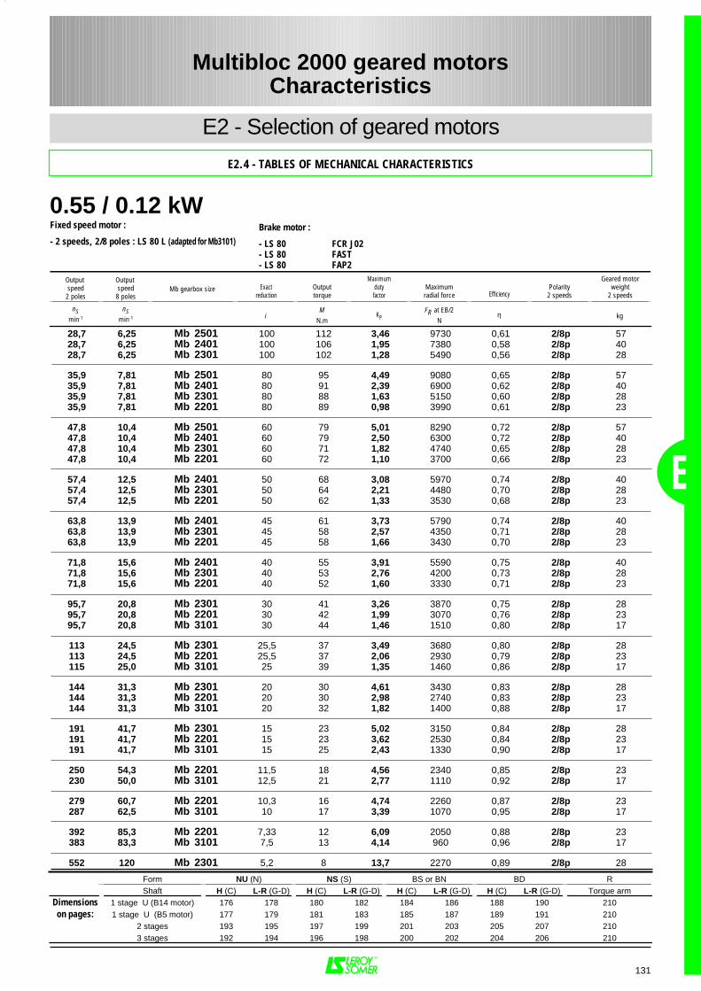
0.55 / 0.12 kW
E
131
28,7 6,25 Mb 2501 100 112 3,46 9730 0,61 2/8p 5728,7 6,25 Mb 2401 100 106 1,95 7380 0,58 2/8p 4028,7 6,25 Mb 2301 100 102 1,28 5490 0,56 2/8p 28
35,9 7,81 Mb 2501 80 95 4,49 9080 0,65 2/8p 5735,9 7,81 Mb 2401 80 91 2,39 6900 0,62 2/8p 4035,9 7,81 Mb 2301 80 88 1,63 5150 0,60 2/8p 2835,9 7,81 Mb 2201 80 89 0,98 3990 0,61 2/8p 23
47,8 10,4 Mb 2501 60 79 5,01 8290 0,72 2/8p 5747,8 10,4 Mb 2401 60 79 2,50 6300 0,72 2/8p 4047,8 10,4 Mb 2301 60 71 1,82 4740 0,65 2/8p 2847,8 10,4 Mb 2201 60 72 1,10 3700 0,66 2/8p 23
57,4 12,5 Mb 2401 50 68 3,08 5970 0,74 2/8p 4057,4 12,5 Mb 2301 50 64 2,21 4480 0,70 2/8p 2857,4 12,5 Mb 2201 50 62 1,33 3530 0,68 2/8p 23
63,8 13,9 Mb 2401 45 61 3,73 5790 0,74 2/8p 4063,8 13,9 Mb 2301 45 58 2,57 4350 0,71 2/8p 2863,8 13,9 Mb 2201 45 58 1,66 3430 0,70 2/8p 23
71,8 15,6 Mb 2401 40 55 3,91 5590 0,75 2/8p 4071,8 15,6 Mb 2301 40 53 2,76 4200 0,73 2/8p 2871,8 15,6 Mb 2201 40 52 1,60 3330 0,71 2/8p 23
95,7 20,8 Mb 2301 30 41 3,26 3870 0,75 2/8p 2895,7 20,8 Mb 2201 30 42 1,99 3070 0,76 2/8p 2395,7 20,8 Mb 3101 30 44 1,46 1510 0,80 2/8p 17
113 24,5 Mb 2301 25,5 37 3,49 3680 0,80 2/8p 28113 24,5 Mb 2201 25,5 37 2,06 2930 0,79 2/8p 23115 25,0 Mb 3101 25 39 1,35 1460 0,86 2/8p 17
144 31,3 Mb 2301 20 30 4,61 3430 0,83 2/8p 28144 31,3 Mb 2201 20 30 2,98 2740 0,83 2/8p 23144 31,3 Mb 3101 20 32 1,82 1400 0,88 2/8p 17
191 41,7 Mb 2301 15 23 5,02 3150 0,84 2/8p 28191 41,7 Mb 2201 15 23 3,62 2530 0,84 2/8p 23191 41,7 Mb 3101 15 25 2,43 1330 0,90 2/8p 17
250 54,3 Mb 2201 11,5 18 4,56 2340 0,85 2/8p 23230 50,0 Mb 3101 12,5 21 2,77 1110 0,92 2/8p 17
279 60,7 Mb 2201 10,3 16 4,74 2260 0,87 2/8p 23287 62,5 Mb 3101 10 17 3,39 1070 0,95 2/8p 17
392 85,3 Mb 2201 7,33 12 6,09 2050 0,88 2/8p 23383 83,3 Mb 3101 7,5 13 4,14 960 0,96 2/8p 17
552 120 Mb 2301 5,2 8 13,7 2270 0,89 2/8p 28
Form NU (N) NS (S) BS or BN BD RShaft H (C) L-R (G-D) H (C) L-R (G-D) H (C) L-R (G-D) H (C) L-R (G-D) Torque arm
Dimensions 1 stage U (B14 motor) 176 178 180 182 184 186 188 190 210on pages: 1 stage U (B5 motor) 177 179 181 183 185 187 189 191 210
2 stages 193 195 197 199 201 203 205 207 2103 stages 192 194 196 198 200 202 204 206 210
Multibloc 2000 geared motorsCharacteristics
E2 - Selection of geared motors
E2.4 - TABLES OF MECHANICAL CHARACTERISTICS
Fixed speed motor :
- 2 speeds, 2/8 poles : LS 80 L (adapted for Mb3101)Brake motor :
- LS 80 FCR J02- LS 80 FAST- LS 80 FAP2
Output speed
2 poles
Output speed
8 polesExact
reductionOutputtorque
Maximumdutyfactor
Maximumradial force Efficiency
Polarity2 speeds
Geared motorweight
2 speeds
nSmin-1
nSmin-1 i
MN.m
KPFR at EB/2
Nη kg
Mb gearbox size
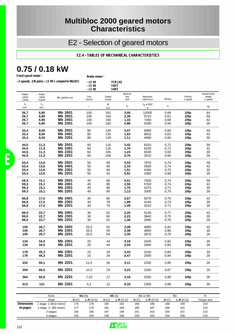
0.75 / 0.18 kW
E
132
26,7 6,80 Mb 2601 100 181 3,95 12000 0,68 2/8p 6426,7 6,80 Mb 2501 100 164 2,36 9710 0,61 2/8p 5926,7 6,80 Mb 2401 100 156 1,33 7260 0,58 2/8p 4226,7 6,80 Mb 2301 100 150 0,88 5290 0,56 2/8p 30
33,4 8,50 Mb 2501 80 139 3,07 9080 0,65 2/8p 5933,4 8,50 Mb 2401 80 133 1,63 6810 0,62 2/8p 4233,4 8,50 Mb 2301 80 129 1,11 4990 0,60 2/8p 30
44,5 11,3 Mb 2501 60 116 3,42 8310 0,72 2/8p 5944,5 11,3 Mb 2401 60 116 1,70 6230 0,72 2/8p 4244,5 11,3 Mb 2301 60 105 1,24 4630 0,65 2/8p 3044,5 11,3 Mb 2201 60 106 0,75 3510 0,66 2/8p 26
53,4 13,6 Mb 2501 50 99 4,03 7870 0,74 2/8p 5953,4 13,6 Mb 2401 50 99 2,10 5920 0,74 2/8p 4253,4 13,6 Mb 2301 50 94 1,51 4390 0,70 2/8p 3053,4 13,6 Mb 2201 50 91 0,91 3380 0,68 2/8p 26
59,3 15,1 Mb 2501 45 89 4,51 7630 0,74 2/8p 5959,3 15,1 Mb 2401 45 89 2,55 5760 0,74 2/8p 4259,3 15,1 Mb 2301 45 86 1,75 4270 0,71 2/8p 3059,3 15,1 Mb 2201 45 85 1,13 3300 0,70 2/8p 26
66,8 17,0 Mb 2401 40 80 2,67 5570 0,75 2/8p 4266,8 17,0 Mb 2301 40 78 1,88 4140 0,73 2/8p 3066,8 17,0 Mb 2201 40 76 1,09 3210 0,71 2/8p 26
89,0 22,7 Mb 2401 30 62 3,25 5140 0,77 2/8p 4289,0 22,7 Mb 2301 30 60 2,23 3840 0,75 2/8p 3089,0 22,7 Mb 2201 30 61 1,36 2990 0,76 2/8p 26
105 26,7 Mb 2401 25,5 55 3,48 4890 0,81 2/8p 42105 26,7 Mb 2301 25,5 55 2,38 3650 0,80 2/8p 30105 26,7 Mb 2201 25,5 54 1,40 2870 0,79 2/8p 26
134 34,0 Mb 2301 20 44 3,19 3420 0,82 2/8p 30134 34,0 Mb 2201 20 44 2,04 2690 0,83 2/8p 26
178 45,3 Mb 2301 15 34 3,43 3150 0,84 2/8p 30178 45,3 Mb 2201 15 34 2,47 2500 0,84 2/8p 26
232 59,1 Mb 2201 11,5 26 3,11 2330 0,85 2/8p 26
259 66,0 Mb 2201 10,3 24 3,23 2260 0,87 2/8p 26
364 92,8 Mb 2201 7,33 17 4,16 2050 0,88 2/8p 26
513 131 Mb 2301 5,2 12 9,33 2300 0,89 2/8p 30
Form NU (N) NS (S) BS or BN BD RShaft H (C) L-R (G-D) H (C) L-R (G-D) H (C) L-R (G-D) H (C) L-R (G-D) Torque arm
Dimensions 1 stage U (B14 motor) 176 178 180 182 184 186 188 190 210on pages: 1 stage U (B5 motor) 177 179 181 183 185 187 189 191 210
2 stages 193 195 197 199 201 203 205 207 2103 stages 192 194 196 198 200 202 204 206 210
Multibloc 2000 geared motorsCharacteristics
E2 - Selection of geared motors
E2.4 - TABLES OF MECHANICAL CHARACTERISTICS
Fixed speed motor :
- 2 speeds, 2/8 poles : LS 90 L (adapted for Mb2201)Brake motor :
- LS 90 FCR J02- LS 90 FAST- LS 90 FAP2
Output speed
2 poles
Output speed
8 polesExact
reductionOutputtorque
Maximumdutyfactor
Maximumradial force Efficiency
Polarity2 speeds
Geared motorweight
2 speeds
nSmin-1
nSmin-1 i
MN.m
KPFR at EB/2
Nη kg
Mb gearbox size
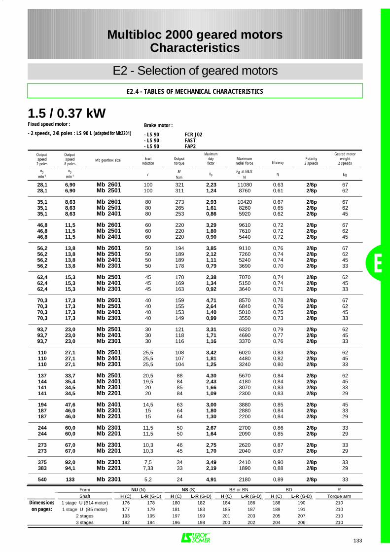
1.5 / 0.37 kW
E
133
28,1 6,90 Mb 2601 100 321 2,23 11080 0,63 2/8p 6728,1 6,90 Mb 2501 100 311 1,24 8760 0,61 2/8p 62
35,1 8,63 Mb 2601 80 273 2,93 10420 0,67 2/8p 6735,1 8,63 Mb 2501 80 265 1,61 8260 0,65 2/8p 6235,1 8,63 Mb 2401 80 253 0,86 5920 0,62 2/8p 45
46,8 11,5 Mb 2601 60 220 3,29 9610 0,72 2/8p 6746,8 11,5 Mb 2501 60 220 1,80 7610 0,72 2/8p 6246,8 11,5 Mb 2401 60 220 0,90 5440 0,72 2/8p 45
56,2 13,8 Mb 2601 50 194 3,85 9110 0,76 2/8p 6756,2 13,8 Mb 2501 50 189 2,12 7260 0,74 2/8p 6256,2 13,8 Mb 2401 50 189 1,11 5240 0,74 2/8p 4556,2 13,8 Mb 2301 50 178 0,79 3690 0,70 2/8p 33
62,4 15,3 Mb 2501 45 170 2,38 7070 0,74 2/8p 6262,4 15,3 Mb 2401 45 169 1,34 5150 0,74 2/8p 4562,4 15,3 Mb 2301 45 163 0,92 3640 0,71 2/8p 33
70,3 17,3 Mb 2601 40 159 4,71 8570 0,78 2/8p 6770,3 17,3 Mb 2501 40 155 2,64 6840 0,76 2/8p 6270,3 17,3 Mb 2401 40 153 1,40 5010 0,75 2/8p 4570,3 17,3 Mb 2301 40 149 0,99 3550 0,73 2/8p 33
93,7 23,0 Mb 2501 30 121 3,31 6320 0,79 2/8p 6293,7 23,0 Mb 2401 30 118 1,71 4690 0,77 2/8p 4593,7 23,0 Mb 2301 30 116 1,16 3370 0,76 2/8p 33
110 27,1 Mb 2501 25,5 108 3,42 6020 0,83 2/8p 62110 27,1 Mb 2401 25,5 107 1,81 4480 0,82 2/8p 45110 27,1 Mb 2301 25,5 104 1,25 3240 0,80 2/8p 33
137 33,7 Mb 2501 20,5 88 4,30 5670 0,84 2/8p 62144 35,4 Mb 2401 19,5 84 2,43 4180 0,84 2/8p 45141 34,5 Mb 2301 20 85 1,66 3070 0,83 2/8p 33141 34,5 Mb 2201 20 84 1,09 2300 0,83 2/8p 29
194 47,6 Mb 2401 14,5 63 3,00 3880 0,85 2/8p 45187 46,0 Mb 2301 15 64 1,80 2880 0,84 2/8p 33187 46,0 Mb 2201 15 64 1,30 2200 0,84 2/8p 29
244 60,0 Mb 2301 11,5 50 2,67 2700 0,86 2/8p 33244 60,0 Mb 2201 11,5 50 1,64 2090 0,85 2/8p 29
273 67,0 Mb 2301 10,3 46 2,75 2620 0,87 2/8p 33273 67,0 Mb 2201 10,3 45 1,70 2040 0,87 2/8p 29
375 92,0 Mb 2301 7,5 34 3,49 2410 0,90 2/8p 33383 94,1 Mb 2201 7,33 33 2,19 1890 0,88 2/8p 29
540 133 Mb 2301 5,2 24 4,91 2180 0,89 2/8p 33
Form NU (N) NS (S) BS or BN BD RShaft H (C) L-R (G-D) H (C) L-R (G-D) H (C) L-R (G-D) H (C) L-R (G-D) Torque arm
Dimensions 1 stage U (B14 motor) 176 178 180 182 184 186 188 190 210on pages: 1 stage U (B5 motor) 177 179 181 183 185 187 189 191 210
2 stages 193 195 197 199 201 203 205 207 2103 stages 192 194 196 198 200 202 204 206 210
Multibloc 2000 geared motorsCharacteristics
E2 - Selection of geared motors
E2.4 - TABLES OF MECHANICAL CHARACTERISTICS
Fixed speed motor :
- 2 speeds, 2/8 poles : LS 90 L (adapted for Mb2201)Brake motor :
- LS 90 FCR J02- LS 90 FAST- LS 90 FAP2
Output speed
2 poles
Output speed
8 polesExact
reductionOutputtorque
Maximumdutyfactor
Maximumradial force Efficiency
Polarity2 speeds
Geared motorweight
2 speeds
nSmin-1
nSmin-1 i
MN.m
KPFR at EB/2
Nη kg
Mb gearbox size
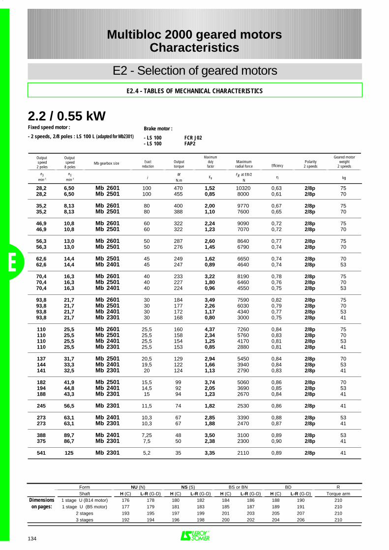
2.2 / 0.55 kW
E
134
28,2 6,50 Mb 2601 100 470 1,52 10320 0,63 2/8p 7528,2 6,50 Mb 2501 100 455 0,85 8000 0,61 2/8p 70
35,2 8,13 Mb 2601 80 400 2,00 9770 0,67 2/8p 7535,2 8,13 Mb 2501 80 388 1,10 7600 0,65 2/8p 70
46,9 10,8 Mb 2601 60 322 2,24 9090 0,72 2/8p 7546,9 10,8 Mb 2501 60 322 1,23 7070 0,72 2/8p 70
56,3 13,0 Mb 2601 50 287 2,60 8640 0,77 2/8p 7556,3 13,0 Mb 2501 50 276 1,45 6790 0,74 2/8p 70
62,6 14,4 Mb 2501 45 249 1,62 6650 0,74 2/8p 7062,6 14,4 Mb 2401 45 247 0,89 4640 0,74 2/8p 53
70,4 16,3 Mb 2601 40 233 3,22 8190 0,78 2/8p 7570,4 16,3 Mb 2501 40 227 1,80 6460 0,76 2/8p 7070,4 16,3 Mb 2401 40 224 0,96 4550 0,75 2/8p 53
93,8 21,7 Mb 2601 30 184 3,49 7590 0,82 2/8p 7593,8 21,7 Mb 2501 30 177 2,26 6030 0,79 2/8p 7093,8 21,7 Mb 2401 30 172 1,17 4340 0,77 2/8p 5393,8 21,7 Mb 2301 30 168 0,80 3000 0,75 2/8p 41
110 25,5 Mb 2601 25,5 160 4,37 7260 0,84 2/8p 75110 25,5 Mb 2501 25,5 158 2,34 5760 0,83 2/8p 70110 25,5 Mb 2401 25,5 154 1,25 4170 0,81 2/8p 53110 25,5 Mb 2301 25,5 153 0,85 2880 0,81 2/8p 41
137 31,7 Mb 2501 20,5 129 2,94 5450 0,84 2/8p 70144 33,3 Mb 2401 19,5 122 1,66 3940 0,84 2/8p 53141 32,5 Mb 2301 20 124 1,13 2790 0,83 2/8p 41
182 41,9 Mb 2501 15,5 99 3,74 5060 0,86 2/8p 70194 44,8 Mb 2401 14,5 92 2,05 3690 0,85 2/8p 53188 43,3 Mb 2301 15 94 1,23 2670 0,84 2/8p 41
245 56,5 Mb 2301 11,5 74 1,82 2530 0,86 2/8p 41
273 63,1 Mb 2401 10,3 67 2,85 3390 0,88 2/8p 53273 63,1 Mb 2301 10,3 67 1,88 2470 0,87 2/8p 41
388 89,7 Mb 2401 7,25 48 3,50 3100 0,89 2/8p 53375 86,7 Mb 2301 7,5 50 2,38 2300 0,90 2/8p 41
541 125 Mb 2301 5,2 35 3,35 2110 0,89 2/8p 41
Form NU (N) NS (S) BS or BN BD RShaft H (C) L-R (G-D) H (C) L-R (G-D) H (C) L-R (G-D) H (C) L-R (G-D) Torque arm
Dimensions 1 stage U (B14 motor) 176 178 180 182 184 186 188 190 210on pages: 1 stage U (B5 motor) 177 179 181 183 185 187 189 191 210
2 stages 193 195 197 199 201 203 205 207 2103 stages 192 194 196 198 200 202 204 206 210
Multibloc 2000 geared motorsCharacteristics
E2 - Selection of geared motors
E2.4 - TABLES OF MECHANICAL CHARACTERISTICS
Fixed speed motor :
- 2 speeds, 2/8 poles : LS 100 L (adapted for Mb2301)Brake motor :
- LS 100 FCR J02- LS 100 FAP2
Output speed
2 poles
Output speed
8 polesExact
reductionOutputtorque
Maximumdutyfactor
Maximumradial force Efficiency
Polarity2 speeds
Geared motorweight
2 speeds
nSmin-1
nSmin-1 i
MN.m
KPFR at EB/2
Nη kg
Mb gearbox size
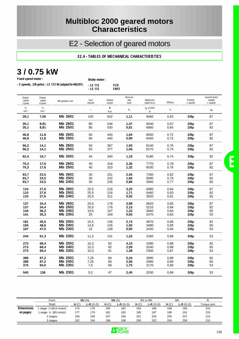
3 / 0.75 kW
E
28,1 7,05 Mb 2601 100 642 1,11 9460 0,63 2/8p 87
35,1 8,81 Mb 2601 80 546 1,47 9040 0,67 2/8p 8735,1 8,81 Mb 2501 80 530 0,81 6860 0,65 2/8p 82
46,8 11,8 Mb 2601 60 440 1,64 8500 0,72 2/8p 8746,8 11,8 Mb 2501 60 440 0,90 6450 0,72 2/8p 82
56,2 14,1 Mb 2601 50 387 1,93 8140 0,76 2/8p 8756,2 14,1 Mb 2501 50 377 1,06 6270 0,74 2/8p 82
62,4 15,7 Mb 2501 45 340 1,19 6180 0,74 2/8p 82
70,3 17,6 Mb 2601 40 318 2,36 7770 0,78 2/8p 8770,3 17,6 Mb 2501 40 310 1,32 6030 0,76 2/8p 82
93,7 23,5 Mb 2601 30 251 2,55 7260 0,82 2/8p 8793,7 23,5 Mb 2501 30 242 1,66 5690 0,79 2/8p 8293,7 23,5 Mb 2401 30 236 0,86 3940 0,77 2/8p 65
110 27,6 Mb 2601 25,5 218 3,20 6980 0,84 2/8p 87110 27,6 Mb 2501 25,5 216 1,71 5460 0,83 2/8p 82110 27,6 Mb 2401 25,5 211 0,92 3820 0,81 2/8p 65
137 34,4 Mb 2601 20,5 178 3,98 6620 0,85 2/8p 87137 34,4 Mb 2501 20,5 176 2,15 5210 0,84 2/8p 82144 36,2 Mb 2401 19,5 167 1,22 3660 0,84 2/8p 65141 35,3 Mb 2301 20 169 0,83 2470 0,83 2/8p 53
181 45,5 Mb 2501 15,5 136 2,74 4870 0,86 2/8p 82194 48,6 Mb 2401 14,5 126 1,50 3480 0,85 2/8p 65187 47,0 Mb 2301 15 128 0,90 2430 0,84 2/8p 53
244 61,3 Mb 2301 11,5 101 1,33 2350 0,86 2/8p 53
273 68,4 Mb 2501 10,3 92 4,10 4390 0,88 2/8p 82273 68,4 Mb 2401 10,3 92 2,09 3240 0,88 2/8p 65273 68,4 Mb 2301 10,3 91 1,38 2300 0,87 2/8p 53
388 97,2 Mb 2501 7,25 66 5,24 3990 0,89 2/8p 82388 97,2 Mb 2401 7,25 66 2,56 2990 0,89 2/8p 65375 94,0 Mb 2301 7,5 69 1,75 2170 0,90 2/8p 53
540 136 Mb 2301 5,2 47 2,45 2030 0,89 2/8p 53
Form NU (N) NS (S) BS or BN BD RShaft H (C) L-R (G-D) H (C) L-R (G-D) H (C) L-R (G-D) H (C) L-R (G-D) Torque arm
Dimensions 1 stage U (B14 motor) 176 178 180 182 184 186 188 190 210on pages: 1 stage U (B5 motor) 177 179 181 183 185 187 189 191 210
2 stages 193 195 197 199 201 203 205 207 2103 stages 192 194 196 198 200 202 204 206 210
Multibloc 2000 geared motorsCharacteristics
135
E2 - Selection of geared motors
E2.4 - TABLES OF MECHANICAL CHARACTERISTICS
Fixed speed motor :
- 2 speeds, 2/8 poles : LS 112 M (adapted for Mb2301)Brake motor :
- LS 112 FCO- LS 112 FAP2
Output speed
2 poles
Output speed
8 polesExact
reductionOutputtorque
Maximumdutyfactor
Maximumradial force Efficiency
Polarity2 speeds
Geared motorweight
2 speeds
nSmin-1
nSmin-1 i
MN.m
KPFR at EB/2
Nη kg
Mb gearbox size
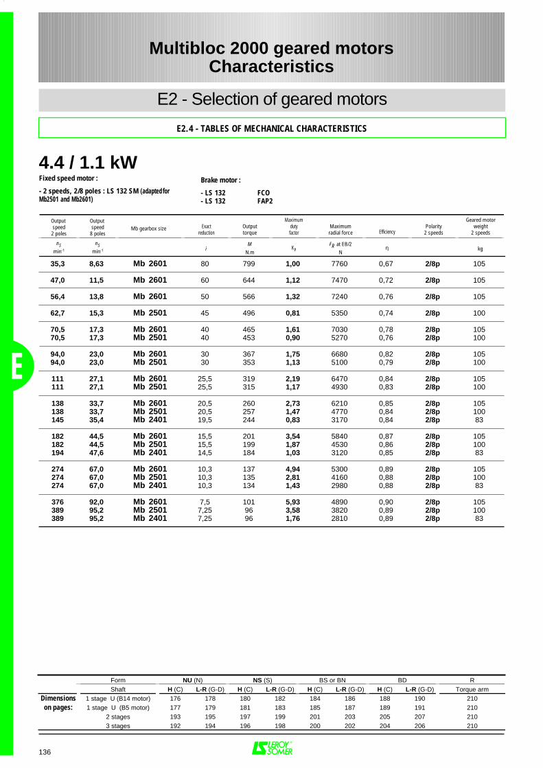
4.4 / 1.1 kW
E
35,3 8,63 Mb 2601 80 799 1,00 7760 0,67 2/8p 105
47,0 11,5 Mb 2601 60 644 1,12 7470 0,72 2/8p 105
56,4 13,8 Mb 2601 50 566 1,32 7240 0,76 2/8p 105
62,7 15,3 Mb 2501 45 496 0,81 5350 0,74 2/8p 100
70,5 17,3 Mb 2601 40 465 1,61 7030 0,78 2/8p 10570,5 17,3 Mb 2501 40 453 0,90 5270 0,76 2/8p 100
94,0 23,0 Mb 2601 30 367 1,75 6680 0,82 2/8p 10594,0 23,0 Mb 2501 30 353 1,13 5100 0,79 2/8p 100
111 27,1 Mb 2601 25,5 319 2,19 6470 0,84 2/8p 105111 27,1 Mb 2501 25,5 315 1,17 4930 0,83 2/8p 100
138 33,7 Mb 2601 20,5 260 2,73 6210 0,85 2/8p 105138 33,7 Mb 2501 20,5 257 1,47 4770 0,84 2/8p 100145 35,4 Mb 2401 19,5 244 0,83 3170 0,84 2/8p 83
182 44,5 Mb 2601 15,5 201 3,54 5840 0,87 2/8p 105182 44,5 Mb 2501 15,5 199 1,87 4530 0,86 2/8p 100194 47,6 Mb 2401 14,5 184 1,03 3120 0,85 2/8p 83
274 67,0 Mb 2601 10,3 137 4,94 5300 0,89 2/8p 105274 67,0 Mb 2501 10,3 135 2,81 4160 0,88 2/8p 100274 67,0 Mb 2401 10,3 134 1,43 2980 0,88 2/8p 83
376 92,0 Mb 2601 7,5 101 5,93 4890 0,90 2/8p 105389 95,2 Mb 2501 7,25 96 3,58 3820 0,89 2/8p 100389 95,2 Mb 2401 7,25 96 1,76 2810 0,89 2/8p 83
Form NU (N) NS (S) BS or BN BD RShaft H (C) L-R (G-D) H (C) L-R (G-D) H (C) L-R (G-D) H (C) L-R (G-D) Torque arm
Dimensions 1 stage U (B14 motor) 176 178 180 182 184 186 188 190 210on pages: 1 stage U (B5 motor) 177 179 181 183 185 187 189 191 210
2 stages 193 195 197 199 201 203 205 207 2103 stages 192 194 196 198 200 202 204 206 210
Multibloc 2000 geared motorsCharacteristics
136
E2 - Selection of geared motors
E2.4 - TABLES OF MECHANICAL CHARACTERISTICS
Fixed speed motor :
- 2 speeds, 2/8 poles : LS 132 SM (adapted forMb2501 and Mb2601)
Brake motor :
- LS 132 FCO- LS 132 FAP2
Output speed
2 poles
Output speed
8 polesExact
reductionOutputtorque
Maximumdutyfactor
Maximumradial force Efficiency
Polarity2 speeds
Geared motorweight
2 speeds
nSmin-1
nSmin-1 i
MN.m
KPFR at EB/2
Nη kg
Mb gearbox size

6.5 / 1.6 kW
E
58,0 14,2 Mb 2601 50 813 0,92 5910 0,76 2/8p 110
72,5 17,8 Mb 2601 40 668 1,12 5930 0,78 2/8p 110
96,7 23,7 Mb 2601 30 527 1,22 5810 0,82 2/8p 11096,7 23,7 Mb 2501 30 507 0,79 4220 0,79 2/8p 105
114 27,8 Mb 2601 25,5 458 1,53 5710 0,84 2/8p 110114 27,8 Mb 2501 25,5 453 0,81 4140 0,83 2/8p 105
141 34,6 Mb 2601 20,5 373 1,90 5590 0,85 2/8p 110141 34,6 Mb 2501 20,5 369 1,02 4130 0,84 2/8p 105
187 45,8 Mb 2601 15,5 289 2,47 5360 0,87 2/8p 110187 45,8 Mb 2501 15,5 285 1,30 4030 0,86 2/8p 105
282 68,9 Mb 2601 10,3 196 3,44 4970 0,89 2/8p 110282 68,9 Mb 2501 10,3 194 1,95 3800 0,88 2/8p 105282 68,9 Mb 2401 10,3 193 0,99 2580 0,88 2/8p 88
387 94,7 Mb 2601 7,5 144 4,13 4640 0,90 2/8p 110400 97,9 Mb 2501 7,25 138 2,50 3560 0,89 2/8p 105400 97,9 Mb 2401 7,25 138 1,22 2520 0,89 2/8p 88
Form NU (N) NS (S) BS or BN BD RShaft H (C) L-R (G-D) H (C) L-R (G-D) H (C) L-R (G-D) H (C) L-R (G-D) Torque arm
Dimensions 1 stage U (B14 motor) 176 178 180 182 184 186 188 190 210on pages: 1 stage U (B5 motor) 177 179 181 183 185 187 189 191 210
2 stages 193 195 197 199 201 203 205 207 2103 stages 192 194 196 198 200 202 204 206 210
Multibloc 2000 geared motorsCharacteristics
137
E2 - Selection of geared motors
E2.4 - TABLES OF MECHANICAL CHARACTERISTICS
Fixed speed motor :
- 2 speeds, 2/8 poles : LS 132 M (adapted for Mb2501and Mb2601)
Brake motor :
- LS 132 FCO- LS 132 FAP2
Output speed
2 poles
Output speed
8 polesExact
reductionOutputtorque
Maximumdutyfactor
Maximumradial force Efficiency
Polarity2 speeds
Geared motorweight
2 speeds
nSmin-1
nSmin-1 i
MN.m
KPFR at EB/2
Nη kg
Mb gearbox size
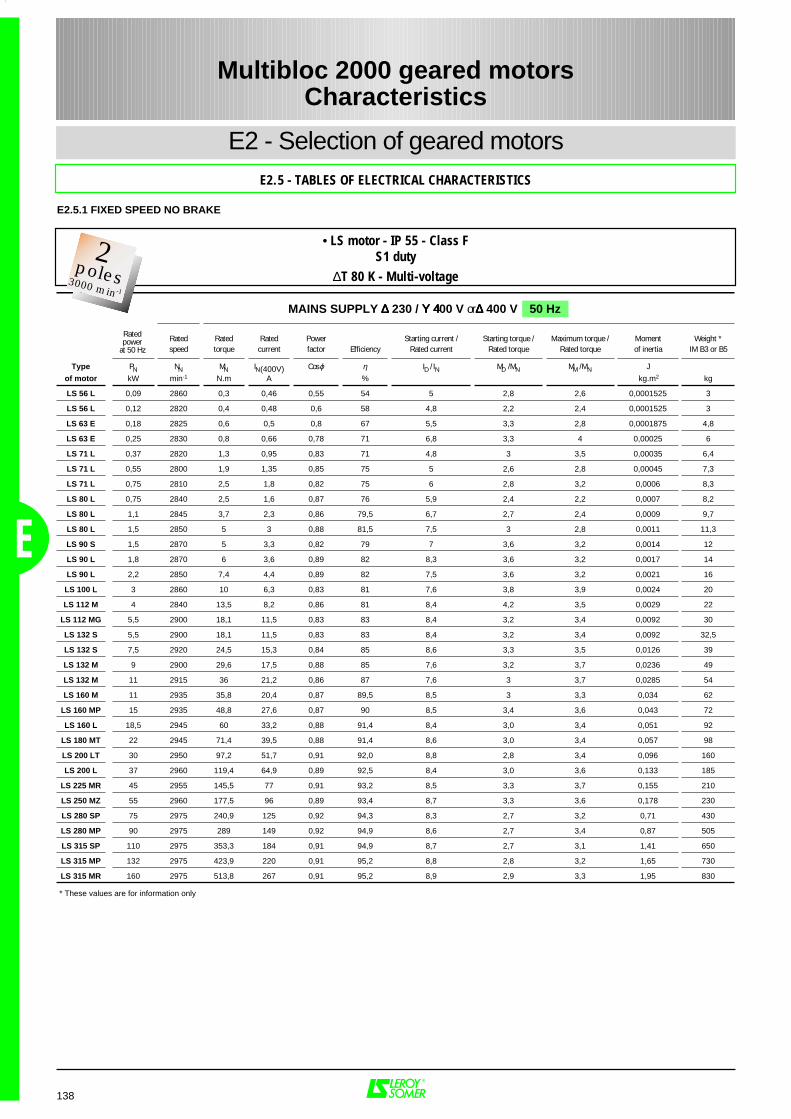
138
E2 - Selection of geared motorsE2.5 - TABLES OF ELECTRICAL CHARACTERISTICS
Multibloc 2000 geared motorsCharacteristics
E
E2.5.1 FIXED SPEED NO BRAKE
Rated Rated Rated Power Starting current / Starting torque / Maximum torque / Moment Weight *speed torque current factor Efficiency Rated current Rated torque Rated torque of inertia IM B3 or B5
Type PN NN MN IN(400V) Cos ϕ η ID / IN MD / MN MM / MN J
of motor kW min-1 N.m A % kg.m2 kg
LS 56 L 0,09 2860 0,3 0,46 0,55 54 5 2,8 2,6 0,0001525 3
LS 56 L 0,12 2820 0,4 0,48 0,6 58 4,8 2,2 2,4 0,0001525 3
LS 63 E 0,18 2825 0,6 0,5 0,8 67 5,5 3,3 2,8 0,0001875 4,8
LS 63 E 0,25 2830 0,8 0,66 0,78 71 6,8 3,3 4 0,00025 6
LS 71 L 0,37 2820 1,3 0,95 0,83 71 4,8 3 3,5 0,00035 6,4
LS 71 L 0,55 2800 1,9 1,35 0,85 75 5 2,6 2,8 0,00045 7,3
LS 71 L 0,75 2810 2,5 1,8 0,82 75 6 2,8 3,2 0,0006 8,3
LS 80 L 0,75 2840 2,5 1,6 0,87 76 5,9 2,4 2,2 0,0007 8,2
LS 80 L 1,1 2845 3,7 2,3 0,86 79,5 6,7 2,7 2,4 0,0009 9,7
LS 80 L 1,5 2850 5 3 0,88 81,5 7,5 3 2,8 0,0011 11,3
LS 90 S 1,5 2870 5 3,3 0,82 79 7 3,6 3,2 0,0014 12
LS 90 L 1,8 2870 6 3,6 0,89 82 8,3 3,6 3,2 0,0017 14
LS 90 L 2,2 2850 7,4 4,4 0,89 82 7,5 3,6 3,2 0,0021 16
LS 100 L 3 2860 10 6,3 0,83 81 7,6 3,8 3,9 0,0024 20
LS 112 M 4 2840 13,5 8,2 0,86 81 8,4 4,2 3,5 0,0029 22
LS 112 MG 5,5 2900 18,1 11,5 0,83 83 8,4 3,2 3,4 0,0092 30
LS 132 S 5,5 2900 18,1 11,5 0,83 83 8,4 3,2 3,4 0,0092 32,5
LS 132 S 7,5 2920 24,5 15,3 0,84 85 8,6 3,3 3,5 0,0126 39
LS 132 M 9 2900 29,6 17,5 0,88 85 7,6 3,2 3,7 0,0236 49
LS 132 M 11 2915 36 21,2 0,86 87 7,6 3 3,7 0,0285 54
LS 160 M 11 2935 35,8 20,4 0,87 89,5 8,5 3 3,3 0,034 62
LS 160 MP 15 2935 48,8 27,6 0,87 90 8,5 3,4 3,6 0,043 72
LS 160 L 18,5 2945 60 33,2 0,88 91,4 8,4 3,0 3,4 0,051 92
LS 180 MT 22 2945 71,4 39,5 0,88 91,4 8,6 3,0 3,4 0,057 98
LS 200 LT 30 2950 97,2 51,7 0,91 92,0 8,8 2,8 3,4 0,096 160
LS 200 L 37 2960 119,4 64,9 0,89 92,5 8,4 3,0 3,6 0,133 185
LS 225 MR 45 2955 145,5 77 0,91 93,2 8,5 3,3 3,7 0,155 210
LS 250 MZ 55 2960 177,5 96 0,89 93,4 8,7 3,3 3,6 0,178 230
LS 280 SP 75 2975 240,9 125 0,92 94,3 8,3 2,7 3,2 0,71 430
LS 280 MP 90 2975 289 149 0,92 94,9 8,6 2,7 3,4 0,87 505
LS 315 SP 110 2975 353,3 184 0,91 94,9 8,7 2,7 3,1 1,41 650
LS 315 MP 132 2975 423,9 220 0,91 95,2 8,8 2,8 3,2 1,65 730
LS 315 MR 160 2975 513,8 267 0,91 95,2 8,9 2,9 3,3 1,95 830
* These values are for information only
Ratedpower
at 50 Hz
MAINS SUPPLY ∆∆∆∆ 230 / ΥΥΥΥ 444400 V or ∆∆∆∆ 400 V 50 Hz
• LS motor - IP 55 - Class FS1 duty
∆T 80 K - Multi-voltage2
Pôles3000 min-1
2poles3000 min-1
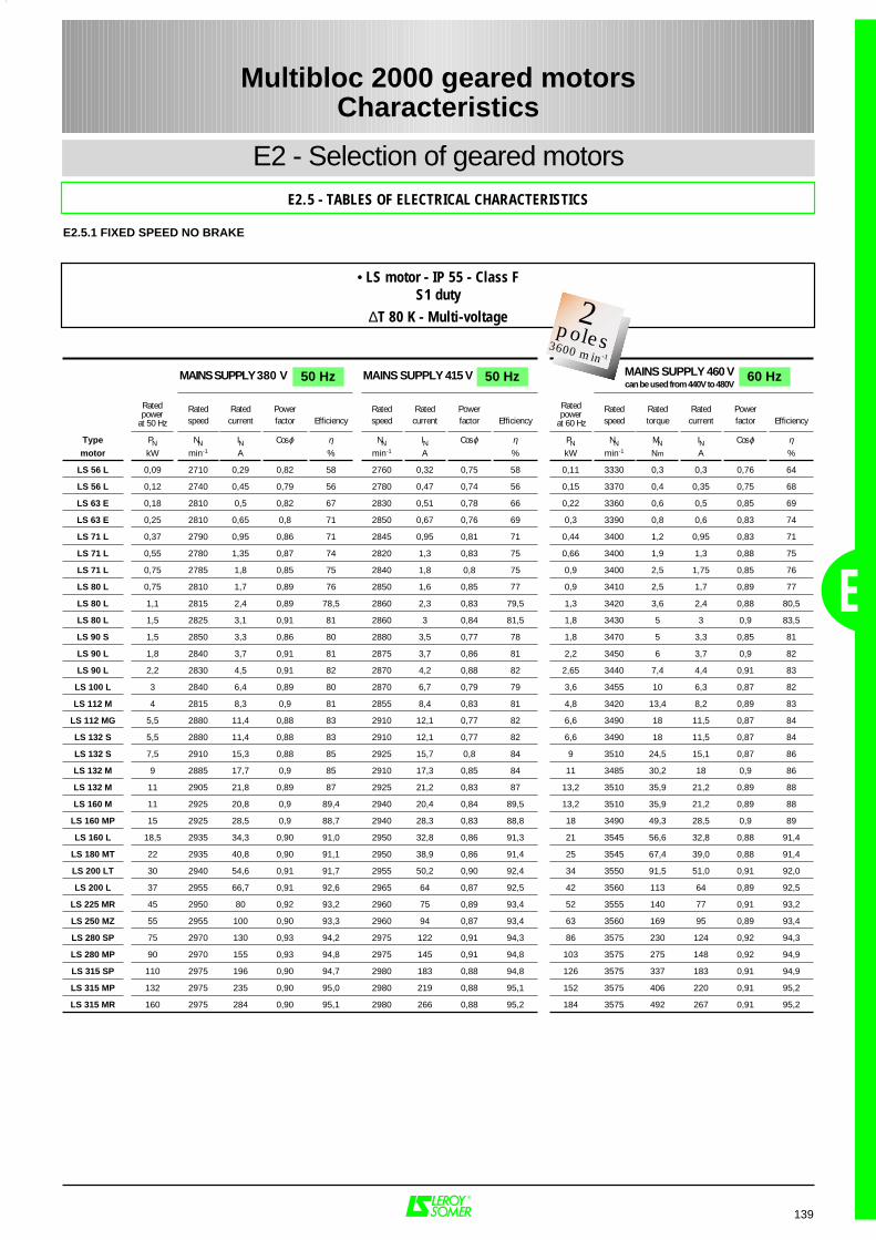
139
E
E2 - Selection of geared motorsE2.5 - TABLES OF ELECTRICAL CHARACTERISTICS
Multibloc 2000 geared motorsCharacteristics
E2.5.1 FIXED SPEED NO BRAKE
Rated Rated Power Rated Rated Power Rated Rated Rated Powerspeed current factor Efficiency speed current factor Efficiency speed torque current factor Efficiency
Type PN NN IN Cos ϕ η NN IN Cos ϕ η PN NN MN IN Cos ϕ ηmotor kW min-1 A % min-1 A % kW min-1 Nm A %
LS 56 L 0,09 2710 0,29 0,82 58 2760 0,32 0,75 58 0,11 3330 0,3 0,3 0,76 64
LS 56 L 0,12 2740 0,45 0,79 56 2780 0,47 0,74 56 0,15 3370 0,4 0,35 0,75 68
LS 63 E 0,18 2810 0,5 0,82 67 2830 0,51 0,78 66 0,22 3360 0,6 0,5 0,85 69
LS 63 E 0,25 2810 0,65 0,8 71 2850 0,67 0,76 69 0,3 3390 0,8 0,6 0,83 74
LS 71 L 0,37 2790 0,95 0,86 71 2845 0,95 0,81 71 0,44 3400 1,2 0,95 0,83 71
LS 71 L 0,55 2780 1,35 0,87 74 2820 1,3 0,83 75 0,66 3400 1,9 1,3 0,88 75
LS 71 L 0,75 2785 1,8 0,85 75 2840 1,8 0,8 75 0,9 3400 2,5 1,75 0,85 76
LS 80 L 0,75 2810 1,7 0,89 76 2850 1,6 0,85 77 0,9 3410 2,5 1,7 0,89 77
LS 80 L 1,1 2815 2,4 0,89 78,5 2860 2,3 0,83 79,5 1,3 3420 3,6 2,4 0,88 80,5
LS 80 L 1,5 2825 3,1 0,91 81 2860 3 0,84 81,5 1,8 3430 5 3 0,9 83,5
LS 90 S 1,5 2850 3,3 0,86 80 2880 3,5 0,77 78 1,8 3470 5 3,3 0,85 81
LS 90 L 1,8 2840 3,7 0,91 81 2875 3,7 0,86 81 2,2 3450 6 3,7 0,9 82
LS 90 L 2,2 2830 4,5 0,91 82 2870 4,2 0,88 82 2,65 3440 7,4 4,4 0,91 83
LS 100 L 3 2840 6,4 0,89 80 2870 6,7 0,79 79 3,6 3455 10 6,3 0,87 82
LS 112 M 4 2815 8,3 0,9 81 2855 8,4 0,83 81 4,8 3420 13,4 8,2 0,89 83
LS 112 MG 5,5 2880 11,4 0,88 83 2910 12,1 0,77 82 6,6 3490 18 11,5 0,87 84
LS 132 S 5,5 2880 11,4 0,88 83 2910 12,1 0,77 82 6,6 3490 18 11,5 0,87 84
LS 132 S 7,5 2910 15,3 0,88 85 2925 15,7 0,8 84 9 3510 24,5 15,1 0,87 86
LS 132 M 9 2885 17,7 0,9 85 2910 17,3 0,85 84 11 3485 30,2 18 0,9 86
LS 132 M 11 2905 21,8 0,89 87 2925 21,2 0,83 87 13,2 3510 35,9 21,2 0,89 88
LS 160 M 11 2925 20,8 0,9 89,4 2940 20,4 0,84 89,5 13,2 3510 35,9 21,2 0,89 88
LS 160 MP 15 2925 28,5 0,9 88,7 2940 28,3 0,83 88,8 18 3490 49,3 28,5 0,9 89
LS 160 L 18,5 2935 34,3 0,90 91,0 2950 32,8 0,86 91,3 21 3545 56,6 32,8 0,88 91,4
LS 180 MT 22 2935 40,8 0,90 91,1 2950 38,9 0,86 91,4 25 3545 67,4 39,0 0,88 91,4
LS 200 LT 30 2940 54,6 0,91 91,7 2955 50,2 0,90 92,4 34 3550 91,5 51,0 0,91 92,0
LS 200 L 37 2955 66,7 0,91 92,6 2965 64 0,87 92,5 42 3560 113 64 0,89 92,5
LS 225 MR 45 2950 80 0,92 93,2 2960 75 0,89 93,4 52 3555 140 77 0,91 93,2
LS 250 MZ 55 2955 100 0,90 93,3 2960 94 0,87 93,4 63 3560 169 95 0,89 93,4
LS 280 SP 75 2970 130 0,93 94,2 2975 122 0,91 94,3 86 3575 230 124 0,92 94,3
LS 280 MP 90 2970 155 0,93 94,8 2975 145 0,91 94,8 103 3575 275 148 0,92 94,9
LS 315 SP 110 2975 196 0,90 94,7 2980 183 0,88 94,8 126 3575 337 183 0,91 94,9
LS 315 MP 132 2975 235 0,90 95,0 2980 219 0,88 95,1 152 3575 406 220 0,91 95,2
LS 315 MR 160 2975 284 0,90 95,1 2980 266 0,88 95,2 184 3575 492 267 0,91 95,2
MAINS SUPPLY 380 V 50 Hz MAINS SUPPLY 460 Vcan be used from 440V to 480V
60 HzMAINS SUPPLY 415 V 50 Hz
Ratedpower
at 50 Hz
Ratedpower
at 60 Hz
• LS motor - IP 55 - Class FS1 duty
∆T 80 K - Multi-voltage 2Pôles3000 min-1
2poles3600 min-1
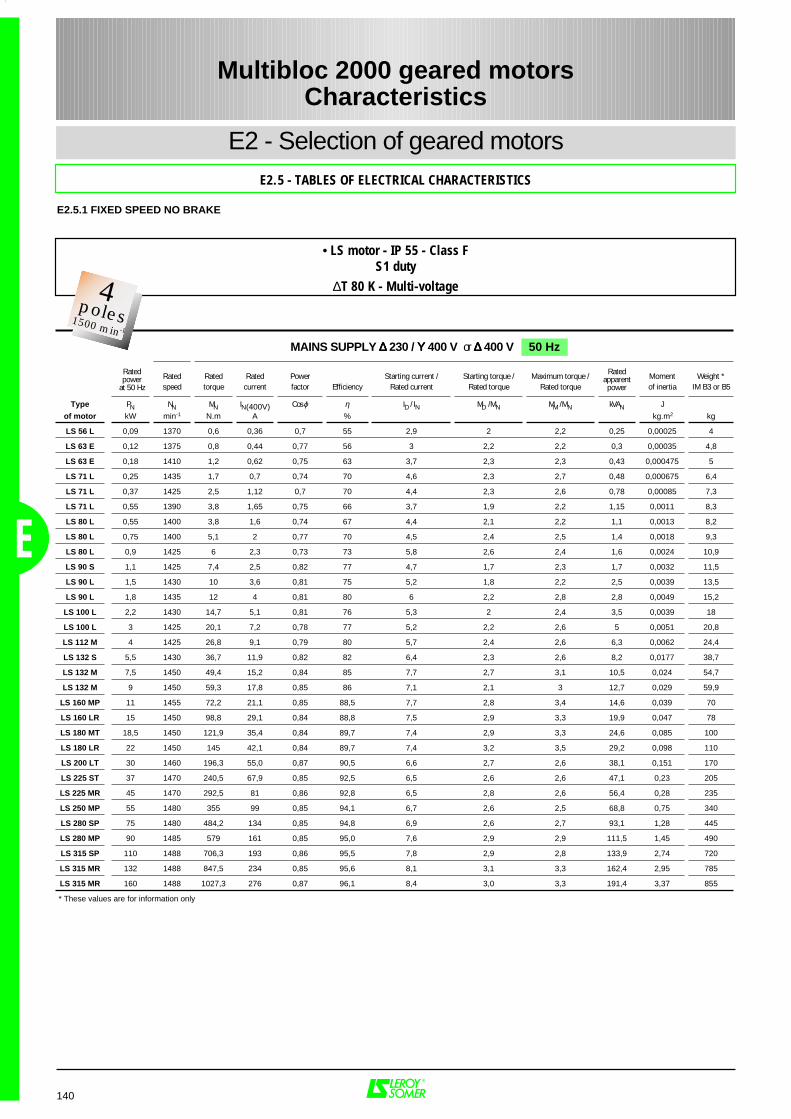
140
E2 - Selection of geared motorsE2.5 - TABLES OF ELECTRICAL CHARACTERISTICS
Multibloc 2000 geared motorsCharacteristics
E
E2.5.1 FIXED SPEED NO BRAKE
Rated Rated Rated Power Starting current / Starting torque / Maximum torque / Moment Weight *speed torque current factor Efficiency Rated current Rated torque Rated torque of inertia IM B3 or B5
Type PN NN MN IN(400V) Cos ϕ η ID / IN MD / MN MM / MN kVAN J
of motor kW min-1 N.m A % kg.m2 kg
LS 56 L 0,09 1370 0,6 0,36 0,7 55 2,9 2 2,2 0,25 0,00025 4
LS 63 E 0,12 1375 0,8 0,44 0,77 56 3 2,2 2,2 0,3 0,00035 4,8
LS 63 E 0,18 1410 1,2 0,62 0,75 63 3,7 2,3 2,3 0,43 0,000475 5
LS 71 L 0,25 1435 1,7 0,7 0,74 70 4,6 2,3 2,7 0,48 0,000675 6,4
LS 71 L 0,37 1425 2,5 1,12 0,7 70 4,4 2,3 2,6 0,78 0,00085 7,3
LS 71 L 0,55 1390 3,8 1,65 0,75 66 3,7 1,9 2,2 1,15 0,0011 8,3
LS 80 L 0,55 1400 3,8 1,6 0,74 67 4,4 2,1 2,2 1,1 0,0013 8,2
LS 80 L 0,75 1400 5,1 2 0,77 70 4,5 2,4 2,5 1,4 0,0018 9,3
LS 80 L 0,9 1425 6 2,3 0,73 73 5,8 2,6 2,4 1,6 0,0024 10,9
LS 90 S 1,1 1425 7,4 2,5 0,82 77 4,7 1,7 2,3 1,7 0,0032 11,5
LS 90 L 1,5 1430 10 3,6 0,81 75 5,2 1,8 2,2 2,5 0,0039 13,5
LS 90 L 1,8 1435 12 4 0,81 80 6 2,2 2,8 2,8 0,0049 15,2
LS 100 L 2,2 1430 14,7 5,1 0,81 76 5,3 2 2,4 3,5 0,0039 18
LS 100 L 3 1425 20,1 7,2 0,78 77 5,2 2,2 2,6 5 0,0051 20,8
LS 112 M 4 1425 26,8 9,1 0,79 80 5,7 2,4 2,6 6,3 0,0062 24,4
LS 132 S 5,5 1430 36,7 11,9 0,82 82 6,4 2,3 2,6 8,2 0,0177 38,7
LS 132 M 7,5 1450 49,4 15,2 0,84 85 7,7 2,7 3,1 10,5 0,024 54,7
LS 132 M 9 1450 59,3 17,8 0,85 86 7,1 2,1 3 12,7 0,029 59,9
LS 160 MP 11 1455 72,2 21,1 0,85 88,5 7,7 2,8 3,4 14,6 0,039 70
LS 160 LR 15 1450 98,8 29,1 0,84 88,8 7,5 2,9 3,3 19,9 0,047 78
LS 180 MT 18,5 1450 121,9 35,4 0,84 89,7 7,4 2,9 3,3 24,6 0,085 100
LS 180 LR 22 1450 145 42,1 0,84 89,7 7,4 3,2 3,5 29,2 0,098 110
LS 200 LT 30 1460 196,3 55,0 0,87 90,5 6,6 2,7 2,6 38,1 0,151 170
LS 225 ST 37 1470 240,5 67,9 0,85 92,5 6,5 2,6 2,6 47,1 0,23 205
LS 225 MR 45 1470 292,5 81 0,86 92,8 6,5 2,8 2,6 56,4 0,28 235
LS 250 MP 55 1480 355 99 0,85 94,1 6,7 2,6 2,5 68,8 0,75 340
LS 280 SP 75 1480 484,2 134 0,85 94,8 6,9 2,6 2,7 93,1 1,28 445
LS 280 MP 90 1485 579 161 0,85 95,0 7,6 2,9 2,9 111,5 1,45 490
LS 315 SP 110 1488 706,3 193 0,86 95,5 7,8 2,9 2,8 133,9 2,74 720
LS 315 MR 132 1488 847,5 234 0,85 95,6 8,1 3,1 3,3 162,4 2,95 785
LS 315 MR 160 1488 1027,3 276 0,87 96,1 8,4 3,0 3,3 191,4 3,37 855
* These values are for information only
Ratedpower
at 50 Hz
MAINS SUPPLY ∆∆∆∆ 230 / ΥΥΥΥ 400 V or ∆∆∆∆ 400 V 50 Hz
Ratedapparentpower
• LS motor - IP 55 - Class FS1 duty
∆T 80 K - Multi-voltage2Pôles3000 min-1
4poles1500 min-1

141
E
E2 - Selection of geared motorsE2.5 - TABLES OF ELECTRICAL CHARACTERISTICS
Multibloc 2000 geared motorsCharacteristics
E2.5.1 FIXED SPEED NO BRAKE
Rated Rated Power Rated Rated Power Rated Rated Rated Powerspeed current factor Efficiency speed current factor Efficiency speed torque current factor Efficiency
Type PN NN IN Cos ϕ η NN IN Cos ϕ η PN NN MN IN Cos ϕ ηof motor kW min-1 A % min-1 A % kW min-1 Nm A %
LS 56 L 0,09 1355 0,36 0,7 54 1390 0,38 0,68 54 0,11 1680 0,6 0,35 0,68 59
LS 63 E 0,12 1350 0,43 0,8 55 1390 0,45 0,75 56 0,15 1660 0,9 0,4 0,76 59
LS 63 E 0,18 1390 0,6 0,78 63 1420 0,63 0,73 62 0,22 1680 1,3 0,6 0,74 62
LS 71 L 0,25 1420 0,7 0,76 70 1440 0,72 0,7 69 0,3 1725 1,7 0,72 0,73 72
LS 71 L 0,37 1420 1,1 0,74 70 1430 1,13 0,68 69 0,44 1720 2,5 1,1 0,71 71
LS 71 L 0,55 1370 1,65 0,78 66 1410 1,68 0,72 65 0,66 1700 3,7 1,5 0,8 72
LS 80 L 0,55 1385 1,7 0,76 66 1410 1,7 0,7 66 0,66 1700 3,7 1,6 0,73 70
LS 80 L 0,75 1380 2 0,8 69 1410 2 0,74 70 0,9 1700 5 2 0,77 73
LS 80 L 0,9 1415 2,4 0,77 73 1435 2,4 0,7 72 1,1 1710 6,1 2,4 0,77 75
LS 90 S 1,1 1410 2,6 0,85 75 1430 2,5 0,8 77 1,3 1715 7,2 2,5 0,84 78
LS 90 L 1,5 1420 3,7 0,83 74 1435 3,6 0,79 74 1,8 1720 10 3,5 0,83 78
LS 90 L 1,8 1420 4,1 0,83 80 1440 4,1 0,77 79 2,2 1730 12,1 4,2 0,83 79
LS 100 L 2,2 1410 5,2 0,85 76 1440 5,2 0,78 76 2,65 1715 14,8 5,1 0,83 79
LS 100 L 3 1415 7,1 0,83 78 1430 7,3 0,74 77 3,6 1725 20 7,1 0,8 81
LS 112 M 4 1415 9,2 0,83 80 1435 9,3 0,76 80 4,8 1730 26,5 9 0,82 83
LS 132 S 5,5 1420 12 0,85 81 1435 11,7 0,8 82 6,6 1730 36,4 11,9 0,84 83
LS 132 M 7,5 1445 15,8 0,85 85 1455 15 0,82 85 9 1750 49,1 15,4 0,85 86
LS 132 M 9 1445 18,3 0,87 86 1455 18,6 0,79 86 11 1745 60 18,2 0,87 87
LS 160 MP 11 1450 21,5 0,88 89 1460 20,9 0,83 89 13,2 1745 68 21,3 0,88 88,5
LS 160 LR 15 1444 29,6 0,87 88,5 1455 29,2 0,81 89,2 18 1740 92,5 29,1 0,86 90,2
LS 180 MT 18,5 1445 36,2 0,87 89,3 1455 34,9 0,82 89,9 21 1750 114,6 35,0 0,84 89,7
LS 180 LR 22 1445 43,5 0,86 89,3 1455 42,1 0,81 89,8 25 1750 136,5 40,9 0,85 90,3
LS 200 LT 30 1450 56,8 0,89 90,1 1465 54,1 0,85 90,7 34 1760 184,6 54,2 0,87 90,5
LS 225 ST 37 1465 70 0,87 92,0 1470 67,0 0,83 92,6 42 1770 226,7 67,0 0,85 92,5
LS 225 MR 45 1465 84 0,88 92,5 1475 79 0,85 92,9 52 1770 280,7 82 0,86 92,8
LS 250 MP 55 1475 102 0,87 93,9 1480 97 0,84 94,3 63 1780 338 99 0,85 94,1
LS 280 SP 75 1480 140 0,86 94,8 1485 132 0,83 95,0 86 1780 462 134 0,85 94,8
LS 280 MP 90 1485 169 0,85 95,0 1488 158 0,83 95,2 103 1785 551 160 0,85 95,0
LS 315 SP 110 1485 204 0,86 95,3 1488 191 0,84 95,5 126 1788 673 193 0,86 95,5
LS 315 MR 132 1485 244 0,86 95,5 1488 229 0,84 95,5 152 1788 812 235 0,85 95,6
LS 315 MR 160 1485 285 0,89 95,8 1488 269 0,86 96,1 184 1788 983 276 0,87 96,1
MAINS SUPPLY 380 V 50 Hz MAINS SUPPLY 460 Vcan be used from 440V to 480V
60 HzMAINS SUPPLY 415 V 50 Hz
Ratedpower
at 50 Hz
Ratedpower
at 60 Hz
• LS motor - IP 55 - Class FS1 duty
∆T 80 K - Multi-voltage 2Pôles3000 min-1
4poles1800 min-1
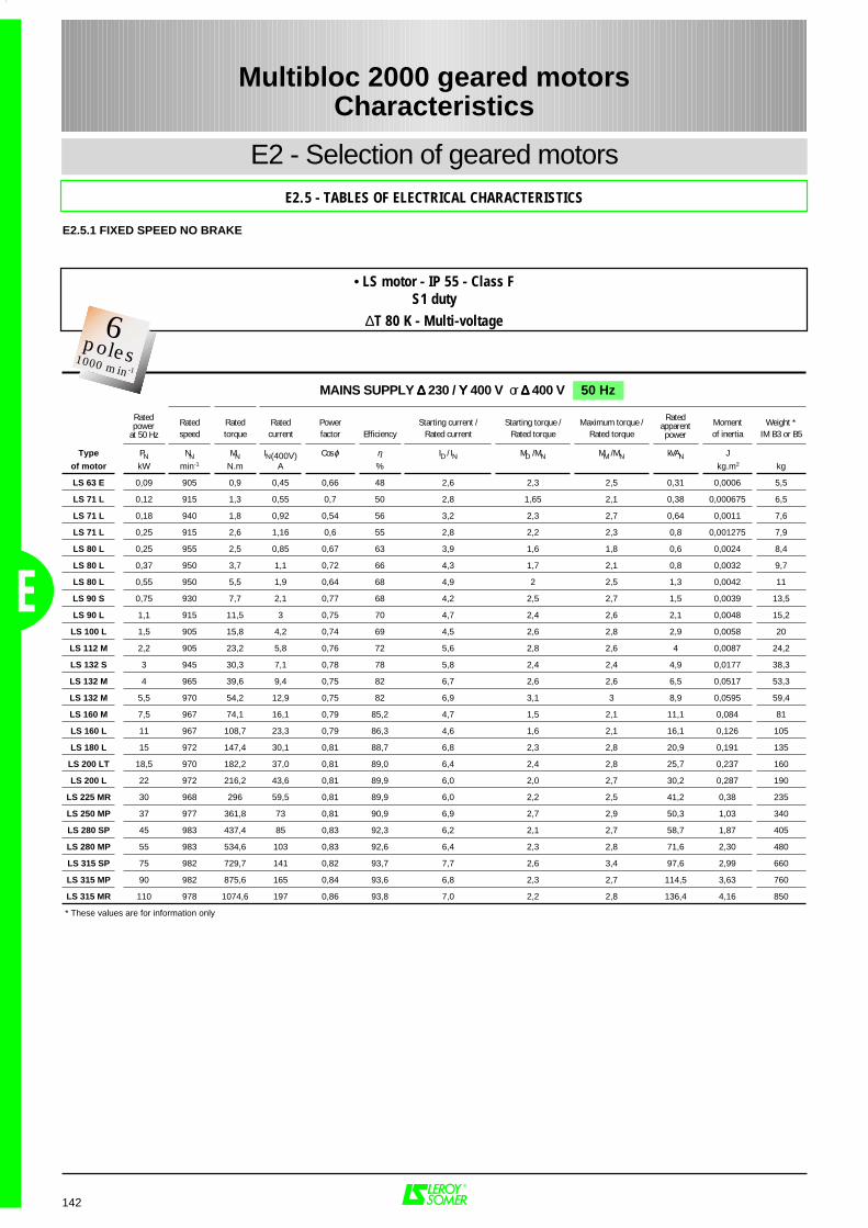
142
E2 - Selection of geared motorsE2.5 - TABLES OF ELECTRICAL CHARACTERISTICS
Multibloc 2000 geared motorsCharacteristics
E
E2.5.1 FIXED SPEED NO BRAKE
Rated Rated Rated Power Starting current / Starting torque / Maximum torque / Moment Weight *speed torque current factor Efficiency Rated current Rated torque Rated torque of inertia IM B3 or B5
Type PN NN MN IN(400V) Cos ϕ η ID / IN MD / MN MM / MN kVAN J
of motor kW min-1 N.m A % kg.m2 kg
LS 63 E 0,09 905 0,9 0,45 0,66 48 2,6 2,3 2,5 0,31 0,0006 5,5
LS 71 L 0,12 915 1,3 0,55 0,7 50 2,8 1,65 2,1 0,38 0,000675 6,5
LS 71 L 0,18 940 1,8 0,92 0,54 56 3,2 2,3 2,7 0,64 0,0011 7,6
LS 71 L 0,25 915 2,6 1,16 0,6 55 2,8 2,2 2,3 0,8 0,001275 7,9
LS 80 L 0,25 955 2,5 0,85 0,67 63 3,9 1,6 1,8 0,6 0,0024 8,4
LS 80 L 0,37 950 3,7 1,1 0,72 66 4,3 1,7 2,1 0,8 0,0032 9,7
LS 80 L 0,55 950 5,5 1,9 0,64 68 4,9 2 2,5 1,3 0,0042 11
LS 90 S 0,75 930 7,7 2,1 0,77 68 4,2 2,5 2,7 1,5 0,0039 13,5
LS 90 L 1,1 915 11,5 3 0,75 70 4,7 2,4 2,6 2,1 0,0048 15,2
LS 100 L 1,5 905 15,8 4,2 0,74 69 4,5 2,6 2,8 2,9 0,0058 20
LS 112 M 2,2 905 23,2 5,8 0,76 72 5,6 2,8 2,6 4 0,0087 24,2
LS 132 S 3 945 30,3 7,1 0,78 78 5,8 2,4 2,4 4,9 0,0177 38,3
LS 132 M 4 965 39,6 9,4 0,75 82 6,7 2,6 2,6 6,5 0,0517 53,3
LS 132 M 5,5 970 54,2 12,9 0,75 82 6,9 3,1 3 8,9 0,0595 59,4
LS 160 M 7,5 967 74,1 16,1 0,79 85,2 4,7 1,5 2,1 11,1 0,084 81
LS 160 L 11 967 108,7 23,3 0,79 86,3 4,6 1,6 2,1 16,1 0,126 105
LS 180 L 15 972 147,4 30,1 0,81 88,7 6,8 2,3 2,8 20,9 0,191 135
LS 200 LT 18,5 970 182,2 37,0 0,81 89,0 6,4 2,4 2,8 25,7 0,237 160
LS 200 L 22 972 216,2 43,6 0,81 89,9 6,0 2,0 2,7 30,2 0,287 190
LS 225 MR 30 968 296 59,5 0,81 89,9 6,0 2,2 2,5 41,2 0,38 235
LS 250 MP 37 977 361,8 73 0,81 90,9 6,9 2,7 2,9 50,3 1,03 340
LS 280 SP 45 983 437,4 85 0,83 92,3 6,2 2,1 2,7 58,7 1,87 405
LS 280 MP 55 983 534,6 103 0,83 92,6 6,4 2,3 2,8 71,6 2,30 480
LS 315 SP 75 982 729,7 141 0,82 93,7 7,7 2,6 3,4 97,6 2,99 660
LS 315 MP 90 982 875,6 165 0,84 93,6 6,8 2,3 2,7 114,5 3,63 760
LS 315 MR 110 978 1074,6 197 0,86 93,8 7,0 2,2 2,8 136,4 4,16 850
* These values are for information only
Ratedpower
at 50 Hz
MAINS SUPPLY ∆∆∆∆ 230 / ΥΥΥΥ 400 V or ∆∆∆∆ 400 V 50 Hz
Ratedapparentpower
• LS motor - IP 55 - Class FS1 duty
∆T 80 K - Multi-voltage2Pôles3000 min-1
6poles1000 min-1
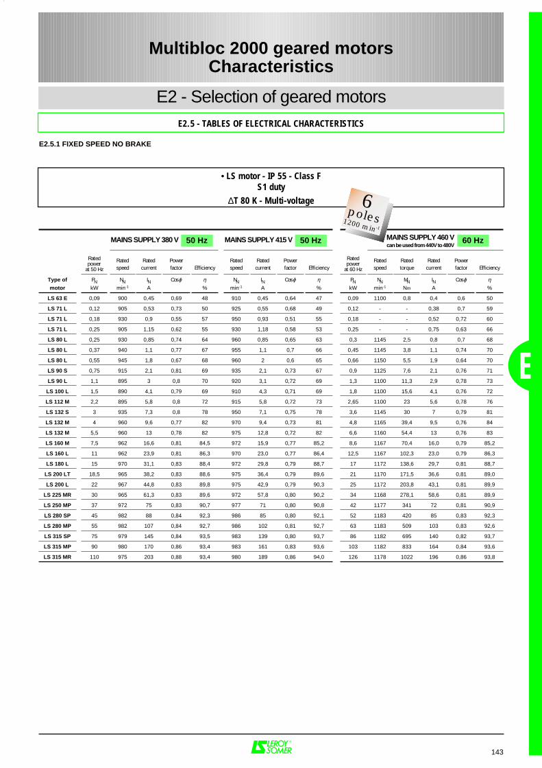
143
E
E2 - Selection of geared motorsE2.5 - TABLES OF ELECTRICAL CHARACTERISTICS
Multibloc 2000 geared motorsCharacteristics
E2.5.1 FIXED SPEED NO BRAKE
Rated Rated Power Rated Rated Power Rated Rated Rated Powerspeed current factor Efficiency speed current factor Efficiency speed torque current factor Efficiency
Type of PN NN IN Cos ϕ η NN IN Cos ϕ η PN NN MN IN Cos ϕ ηmotor kW min-1 A % min-1 A % kW min-1 Nm A %
LS 63 E 0,09 900 0,45 0,69 48 910 0,45 0,64 47 0,09 1100 0,8 0,4 0,6 50
LS 71 L 0,12 905 0,53 0,73 50 925 0,55 0,68 49 0,12 - - 0,38 0,7 59
LS 71 L 0,18 930 0,9 0,55 57 950 0,93 0,51 55 0,18 - - 0,52 0,72 60
LS 71 L 0,25 905 1,15 0,62 55 930 1,18 0,58 53 0,25 - - 0,75 0,63 66
LS 80 L 0,25 930 0,85 0,74 64 960 0,85 0,65 63 0,3 1145 2,5 0,8 0,7 68
LS 80 L 0,37 940 1,1 0,77 67 955 1,1 0,7 66 0,45 1145 3,8 1,1 0,74 70
LS 80 L 0,55 945 1,8 0,67 68 960 2 0,6 65 0,66 1150 5,5 1,9 0,64 70
LS 90 S 0,75 915 2,1 0,81 69 935 2,1 0,73 67 0,9 1125 7,6 2,1 0,76 71
LS 90 L 1,1 895 3 0,8 70 920 3,1 0,72 69 1,3 1100 11,3 2,9 0,78 73
LS 100 L 1,5 890 4,1 0,79 69 910 4,3 0,71 69 1,8 1100 15,6 4,1 0,76 72
LS 112 M 2,2 895 5,8 0,8 72 915 5,8 0,72 73 2,65 1100 23 5,6 0,78 76
LS 132 S 3 935 7,3 0,8 78 950 7,1 0,75 78 3,6 1145 30 7 0,79 81
LS 132 M 4 960 9,6 0,77 82 970 9,4 0,73 81 4,8 1165 39,4 9,5 0,76 84
LS 132 M 5,5 960 13 0,78 82 975 12,8 0,72 82 6,6 1160 54,4 13 0,76 83
LS 160 M 7,5 962 16,6 0,81 84,5 972 15,9 0,77 85,2 8,6 1167 70,4 16,0 0,79 85,2
LS 160 L 11 962 23,9 0,81 86,3 970 23,0 0,77 86,4 12,5 1167 102,3 23,0 0,79 86,3
LS 180 L 15 970 31,1 0,83 88,4 972 29,8 0,79 88,7 17 1172 138,6 29,7 0,81 88,7
LS 200 LT 18,5 965 38,2 0,83 88,6 975 36,4 0,79 89,6 21 1170 171,5 36,6 0,81 89,0
LS 200 L 22 967 44,8 0,83 89,8 975 42,9 0,79 90,3 25 1172 203,8 43,1 0,81 89,9
LS 225 MR 30 965 61,3 0,83 89,6 972 57,8 0,80 90,2 34 1168 278,1 58,6 0,81 89,9
LS 250 MP 37 972 75 0,83 90,7 977 71 0,80 90,8 42 1177 341 72 0,81 90,9
LS 280 SP 45 982 88 0,84 92,3 986 85 0,80 92,1 52 1183 420 85 0,83 92,3
LS 280 MP 55 982 107 0,84 92,7 986 102 0,81 92,7 63 1183 509 103 0,83 92,6
LS 315 SP 75 979 145 0,84 93,5 983 139 0,80 93,7 86 1182 695 140 0,82 93,7
LS 315 MP 90 980 170 0,86 93,4 983 161 0,83 93,6 103 1182 833 164 0,84 93,6
LS 315 MR 110 975 203 0,88 93,4 980 189 0,86 94,0 126 1178 1022 196 0,86 93,8
MAINS SUPPLY 380 V 50 Hz MAINS SUPPLY 460 Vcan be used from 440V to 480V
60 HzMAINS SUPPLY 415 V 50 Hz
Ratedpower
at 50 Hz
Ratedpower
at 60 Hz
• LS motor - IP 55 - Class FS1 duty
∆T 80 K - Multi-voltage 2Pôles3000 min-1
6poles1200 min-1
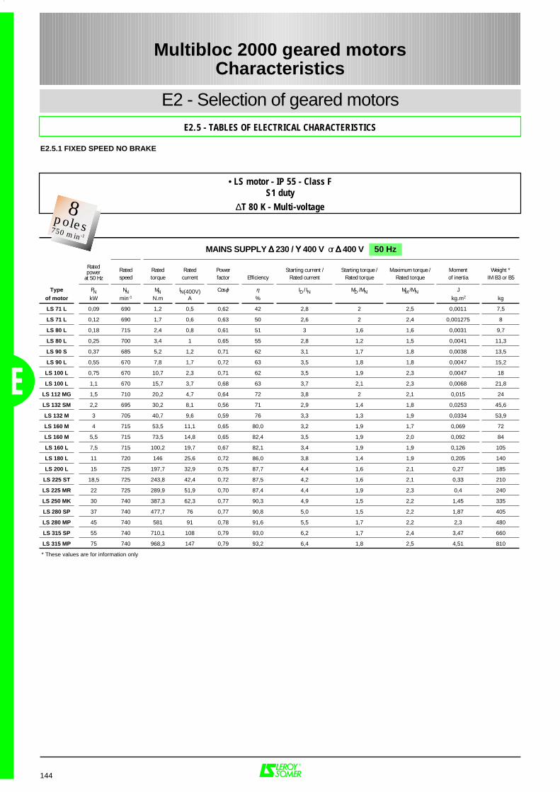
144
E2 - Selection of geared motorsE2.5 - TABLES OF ELECTRICAL CHARACTERISTICS
Multibloc 2000 geared motorsCharacteristics
E
E2.5.1 FIXED SPEED NO BRAKE
Rated Rated Rated Power Starting current / Starting torque / Maximum torque / Moment Weight *speed torque current factor Efficiency Rated current Rated torque Rated torque of inertia IM B3 or B5
Type PN NN MN IN(400V) Cos ϕ η ID / IN MD / MN MM / MN J
of motor kW min-1 N.m A % kg.m2 kg
LS 71 L 0,09 690 1,2 0,5 0,62 42 2,8 2 2,5 0,0011 7,5
LS 71 L 0,12 690 1,7 0,6 0,63 50 2,6 2 2,4 0,001275 8
LS 80 L 0,18 715 2,4 0,8 0,61 51 3 1,6 1,6 0,0031 9,7
LS 80 L 0,25 700 3,4 1 0,65 55 2,8 1,2 1,5 0,0041 11,3
LS 90 S 0,37 685 5,2 1,2 0,71 62 3,1 1,7 1,8 0,0038 13,5
LS 90 L 0,55 670 7,8 1,7 0,72 63 3,5 1,8 1,8 0,0047 15,2
LS 100 L 0,75 670 10,7 2,3 0,71 62 3,5 1,9 2,3 0,0047 18
LS 100 L 1,1 670 15,7 3,7 0,68 63 3,7 2,1 2,3 0,0068 21,8
LS 112 MG 1,5 710 20,2 4,7 0,64 72 3,8 2 2,1 0,015 24
LS 132 SM 2,2 695 30,2 8,1 0,56 71 2,9 1,4 1,8 0,0253 45,6
LS 132 M 3 705 40,7 9,6 0,59 76 3,3 1,3 1,9 0,0334 53,9
LS 160 M 4 715 53,5 11,1 0,65 80,0 3,2 1,9 1,7 0,069 72
LS 160 M 5,5 715 73,5 14,8 0,65 82,4 3,5 1,9 2,0 0,092 84
LS 160 L 7,5 715 100,2 19,7 0,67 82,1 3,4 1,9 1,9 0,126 105
LS 180 L 11 720 146 25,6 0,72 86,0 3,8 1,4 1,9 0,205 140
LS 200 L 15 725 197,7 32,9 0,75 87,7 4,4 1,6 2,1 0,27 185
LS 225 ST 18,5 725 243,8 42,4 0,72 87,5 4,2 1,6 2,1 0,33 210
LS 225 MR 22 725 289,9 51,9 0,70 87,4 4,4 1,9 2,3 0,4 240
LS 250 MK 30 740 387,3 62,3 0,77 90,3 4,9 1,5 2,2 1,45 335
LS 280 SP 37 740 477,7 76 0,77 90,8 5,0 1,5 2,2 1,87 405
LS 280 MP 45 740 581 91 0,78 91,6 5,5 1,7 2,2 2,3 480
LS 315 SP 55 740 710,1 108 0,79 93,0 6,2 1,7 2,4 3,47 660
LS 315 MP 75 740 968,3 147 0,79 93,2 6,4 1,8 2,5 4,51 810
* These values are for information only
Ratedpower
at 50 Hz
MAINS SUPPLY ∆∆∆∆ 230 / ΥΥΥΥ 400 V or ∆∆∆∆ 400 V 50 Hz
• LS motor - IP 55 - Class FS1 duty
∆T 80 K - Multi-voltage2Pôles3000 min-1
8poles750 min-1

145
E
E2 - Selection of geared motorsE2.5 - TABLES OF ELECTRICAL CHARACTERISTICS
Multibloc 2000 geared motorsCharacteristics
E2.5.1 FIXED SPEED NO BRAKE
Rated Rated Power Rated Rated Power Rated Rated Rated Powerspeed current factor Efficiency speed current factor Efficiency speed torque current factor Efficiency
Type PN NN IN Cos ϕ η NN IN Cos ϕ η PN NN MN IN Cos ϕ ηof motor kW min-1 A % min-1 A % kW min-1 Nm A %
LS 71 L 0,09 680 0,5 0,63 40 700 0,5 0,6 40 0,09 850 1 0,42 0,6 45
LS 71 L 0,12 685 0,6 0,65 50 700 0,6 0,6 49 0,12 850 1,3 0,5 0,6 52
LS 80 L 0,18 700 0,74 0,66 53 710 0,8 0,6 52 0,22 855 2,5 0,78 0,62 57
LS 80 L 0,25 700 0,96 0,69 57 710 1 0,62 55 0,3 850 3,4 0,95 0,66 60
LS 90 S 0,37 670 1,2 0,75 62 690 1,2 0,69 62 0,45 835 5,1 1,2 0,71 67
LS 90 L 0,55 655 1,8 0,74 62 680 1,8 0,67 64 0,66 810 7,8 1,8 0,71 67
LS 100 L 0,75 660 2,4 0,76 62 675 2,4 0,69 61 0,9 820 10,5 2,3 0,72 68
LS 100 L 1,1 655 3,6 0,73 63 675 3,9 0,64 62 1,3 820 15,1 3,6 0,73 63
LS 112 MG 1,5 705 4,7 0,68 71 720 4,9 0,61 72 1,8 860 20 4,6 0,66 76
LS 132 SM 2,2 690 7,8 0,59 72 705 8,3 0,52 71 2,6 855 29 7,5 0,59 75
LS 132 M 3 695 9,5 0,64 75 710 9,8 0,57 75 3,6 845 40,7 9,5 0,62 77
LS 160 M 4 710 11,4 0,67 79,8 720 11,0 0,63 80,5 4,6 865 50,8 11,1 0,65 80,0
LS 160 M 5,5 715 14,6 0,69 82,7 725 14,9 0,62 82,7 6,3 865 69,6 14,8 0,65 82,4
LS 160 L 7,5 705 20,0 0,70 81,5 720 19,8 0,64 82,2 8,6 865 95,0 19,6 0,67 82,1
LS 180 L 11 715 26,0 0,75 85,6 725 25,3 0,70 86,3 12,5 870 137,0 25,3 0,72 86,0
LS 200 L 15 720 34,1 0,77 86,8 725 33,2 0,72 87,2 17 875 185,6 32,4 0,75 87,7
LS 225 ST 18,5 720 43,1 0,75 87,0 725 42,1 0,70 87,4 21 875 229,3 41,8 0,72 87,5
LS 225 MR 22 720 52,4 0,73 87,4 730 53,4 0,66 86,8 25 875 273,0 51,3 0,70 87,4
LS 250 MK 30 740 64,0 0,79 90,2 740 61,7 0,75 90,2 34 890 365,0 61,4 0,77 90,3
LS 280 SP 37 740 77 0,80 90,8 740 75 0,76 90,8 42 890 451 75 0,77 90,8
LS 280 MP 45 740 93 0,80 91,7 740 90 0,76 91,6 52 890 558 91 0,78 91,6
LS 315 SP 55 740 113 0,80 92,8 740 107 0,77 93,2 63 740 813 108 0,79 93,0
LS 315 MP 75 740 153 0,80 93,2 740 145 0,77 93,4 86 740 1110 147 0,79 93,2
380 V SUPPLY 50 Hz MAINS SUPPLY 460 Vcan be used from 440V to 480V
60 Hz415 V SUPPLY 50 Hz
Ratedpower
at 50 Hz
Ratedpower
at 60 Hz
• LS motor - IP 55 - Class FS1 duty
∆T 80 K - Multi-voltage 2Pôles3000 min-1
8poles900 min-1
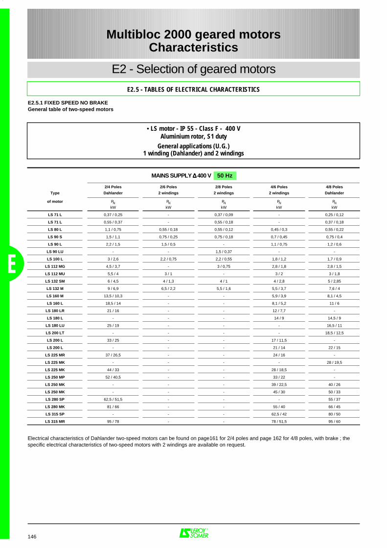
146
E2 - Selection of geared motors
E2.5 - TABLES OF ELECTRICAL CHARACTERISTICS
Multibloc 2000 geared motorsCharacteristics
E
2/4 Poles 2/6 Poles 2/8 Poles 4/6 Poles 4/8 Poles
Type Dahlander 2 windings 2 windings 2 windings Dahlander
of motor PN PN PN PN PNkW kW kW kW kW
LS 71 L 0,37 / 0,25 - 0,37 / 0,09 - 0,25 / 0,12
LS 71 L 0,55 / 0,37 - 0,55 / 0,18 - 0,37 / 0,18
LS 80 L 1,1 / 0,75 0,55 / 0,18 0,55 / 0,12 0,45 / 0,3 0,55 / 0,22
LS 90 S 1,5 / 1,1 0,75 / 0,25 0,75 / 0,18 0,7 / 0,45 0,75 / 0,4
LS 90 L 2,2 / 1,5 1,5 / 0,5 - 1,1 / 0,75 1,2 / 0,6
LS 90 LU - - 1,5 / 0,37 - -
LS 100 L 3 / 2,6 2,2 / 0,75 2,2 / 0,55 1,8 / 1,2 1,7 / 0,9
LS 112 MG 4,5 / 3,7 - 3 / 0,75 2,8 / 1,8 2,8 / 1,5
LS 112 MU 5,5 / 4 3 / 1 - 3 / 2 3 / 1,8
LS 132 SM 6 / 4,5 4 / 1,3 4 / 1 4 / 2,8 5 / 2,85
LS 132 M 9 / 6,9 6,5 / 2,2 5,5 / 1,6 5,5 / 3,7 7,6 / 4
LS 160 M 13,5 / 10,3 - - 5,9 / 3,9 8,1 / 4,5
LS 160 L 18,5 / 14 - - 8,1 / 5,2 11 / 6
LS 180 LR 21 / 16 - - 12 / 7,7 -
LS 180 L - - - 14 / 9 14,5 / 9
LS 180 LU 25 / 19 - - - 16,5 / 11
LS 200 LT - - - - 18,5 / 12,5
LS 200 L 33 / 25 - - 17 / 11,5 -
LS 200 L - - - 21 / 14 22 / 15
LS 225 MR 37 / 26,5 - - 24 / 16 -
LS 225 MK - - - - 28 / 19,5
LS 225 MK 44 / 33 - - 28 / 18,5 -
LS 250 MP 52 / 40,5 - - 33 / 22 -
LS 250 MK - - - 39 / 22,5 40 / 26
LS 250 MK - - - 45 / 30 50 / 33
LS 280 SP 62,5 / 51,5 - - - 55 / 37
LS 280 MK 81 / 66 - - 55 / 40 66 / 45
LS 315 SP - - - 62,5 / 42 80 / 50
LS 315 MR 95 / 78 - - 78 / 51,5 95 / 60
MAINS SUPPLY ∆∆∆∆ 400 V 50 Hz
Electrical characteristics of Dahlander two-speed motors can be found on page161 for 2/4 poles and page 162 for 4/8 poles, with brake ; thespecific electrical characteristics of two-speed motors with 2 windings are available on request.
E2.5.1 FIXED SPEED NO BRAKEGeneral table of two-speed motors
• LS motor - IP 55 - Class F - 400 VAluminium rotor, S1 duty
General applications (U.G.)1 winding (Dahlander) and 2 windings
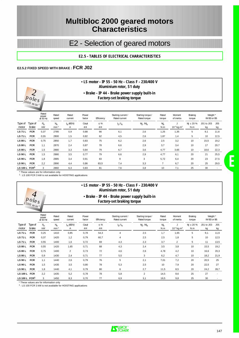
147
Rated Rated Power Starting current / Starting torque / Rated Moment Braking Weight *speed current factor Efficiency Rated current Rated torque torque of inertia torque IM B3 or B5
Type of Type of PN NN IN (400 V) Cos ϕ η % ID / IN MD / MN MN J Mf ± 20 % J01 to J03 J05
motor brake kW min-1 A 4/4 4/4 N.m 10-3 kg.m2 N.m kg kg
LS 71 L FCR 0,37 2785 0,9 0,88 66 6,1 2,6 1,25 1,35 5 9,1 11,6
LS 71 L FCR 0,55 2800 1,5 0,82 62 4,5 2,6 1,87 1,4 5 10 12,5
LS 80 L FCR 0,75 2850 1,7 0,83 75 6,2 2,6 2,5 3,2 10 15,5 19,2
LS 80 L FCR 1,1 2870 2,4 0,87 78 6,6 2,9 3,7 3,4 10 17 20,7
LS 80 L FCR 1,5 2880 3,3 0,84 79 6,7 3,6 4,77 3,65 10 18,6 22,3
LS 90 L FCR 1,5 2880 3,5 0,77 79 6,6 2,9 4,77 6,1 20 21 25,5
LS 90 L FCR 1,8 2885 3,4 0,91 83 9 3 5,72 6,4 20 23 27,5
LS 90 L FCR 2,2 2890 4,4 0,86 83,5 7,4 3,3 7 6,7 20 25 29,5
LS 100 L FCR1 3 2860 6,3 0,83 81 7,6 3,8 10 7,1 25 30 -
Ratedpower
at 50 Hz
E
E2 - Selection of geared motors
E2.5 - TABLES OF ELECTRICAL CHARACTERISTICS
Rated Rated Power Starting current / Starting torque / Rated Moment Braking Weight *speed current factor Efficiency Rated current Rated torque torque of inertia torque IM B3 or B5
Type of Type of PN NN IN (400 V) Cos ϕ η % ID / IN MD / MN MN J Mf ± 20 % J01 to J03 J05
motor brake kW min-1 A 4/4 4/4 N.m 10-3 kg.m2 N.m kg kg
LS 71 L FCR 0,25 1410 0,85 0,78 54,3 4 2,5 1,7 1,65 5 9,1 11,6
LS 71 L FCR 0,37 1420 1,2 0,79 60,7 4 2,5 2,5 1,8 5 10 12,5
LS 71 L FCR 0,55 1400 1,6 0,72 69 4,3 2,3 3,7 2 5 11 13,5
LS 80 L FCR 0,55 1420 1,65 0,71 68 4,3 2,4 3,5 3,8 10 15,5 19,2
LS 80 L FCR 0,75 1400 2 0,73 72 4,6 2,6 4,78 4,2 10 16,6 20,3
LS 80 L FCR 0,9 1430 2,4 0,71 77 5,5 3 6,2 4,7 10 18,2 21,9
LS 90 L FCR 1,1 1440 2,6 0,79 76 5 2,1 7,01 7,2 20 20,5 25
LS 90 L FCR 1,5 1435 3,5 0,80 78 5,3 2,5 10 7,9 20 22,5 27
LS 90 L FCR 1,8 1440 4,1 0,79 80 6 2,7 11,5 8,5 20 24,2 28,7
LS 100 L FCR 2,2 1435 5,2 0,78 78 5,8 2 14,5 8,6 25 27 -
LS 100 L FCR1 3 1450 8,3 0,70 77 6,9 3,1 19,5 9,8 25 30 -
• LS motor - IP 55 - 50 Hz - Class F - 230/400 VAluminium rotor, S1 duty
• Brake - IP 44 - Brake power supply built-inFactory-set braking torque
Ratedpower
at 50 Hz
Multibloc 2000 geared motorsCharacteristics
E2.5.2 FIXED SPEED WITH BRAKE : FCR J02
* These values are for information only1 : LS 100 FCR 3 kW is not available for HOISTING applications
• LS motor - IP 55 - 50 Hz - Class F - 230/400 VAluminium rotor, S1 duty
• Brake - IP 44 - Brake power supply built-inFactory-set braking torque
2Pôles3000 min-1
2poles3000 min-1
2Pôles3000 min-1
4poles1500 min-1
* These values are for information only 1 : LS 100 FCR 3 kW is not available for HOISTING applications
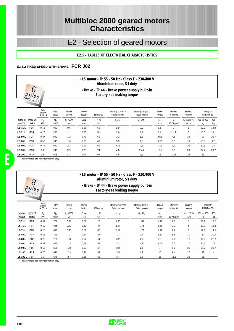
148
E2 - Selection of geared motors
E2.5 - TABLES OF ELECTRICAL CHARACTERISTICS
• LS motor - IP 55 - 50 Hz - Class F - 230/400 VAluminium rotor, S1 duty
• Brake - IP 44 - Brake power supply built-inFactory-set braking torque
Rated Rated Power Starting current / Starting torque / Rated Moment Braking Weight *speed current factor Efficiency Rated current Rated torque torque of inertia torque IM B3 or B5
Type of Type of PN NN IN (400 V) Cos ϕ η % ID / IN MD / MN MN J Mf ± 20 % J01 to J03 J05
motor brake kW min-1 A 4/4 4/4 N.m 10-3 kg.m2 N.m kg kg
LS 71 L FCR 0,18 930 0,6 0,58 55 2,9 2,3 1,8 2 5 10,3 12,8
LS 71 L FCR 0,25 930 1,1 0,65 51 2,8 1,9 2,6 2,15 5 10,6 13,1
LS 80 L FCR 0,37 940 1,2 0,73 61 3,2 1,8 3,53 4,8 10 17 20,7
LS 80 L FCR 0,55 945 1,6 0,73 66 3,5 1,8 5,23 5,5 10 18,3 22
LS 90 L FCR 0,75 940 2,3 0,69 69 4,75 2,5 7,16 7,7 20 22,5 27
LS 90 L FCR 1,1 945 2,9 0,73 74 4,8 2,45 10,5 8,3 20 24,2 28,7
LS 100 L FCR 1,5 905 4,2 0,74 69 4,5 2,6 15 10,5 25 29 -
Ratedpower
at 50 Hz
Rated Rated Power Starting current / Starting torque / Rated Moment Braking Weight *speed current factor Efficiency Rated current Rated torque torque of inertia torque IM B3 or B5
Type of Type of PN NN IN (400 V) Cos ϕ η % ID / IN MD / MN MN J Mf ± 20 % J01 to J03 J05
motor brake kW min-1 A 4/4 4/4 N.m 10-3 kg.m2 N.m kg kg
LS 71 L FCR 0,09 700 0,76 0,61 28 1,95 1,52 1,31 2,1 5 10,2 12,7
LS 71 L FCR 0,12 655 0,72 0,62 44 1,97 1,43 1,53 2,2 5 10,7 13,2
LS 71 L FCR 0,15 675 0,75 0,60 48 2,17 1,73 1,91 2,2 5 12,1 14,6
LS 80 L FCR 0,18 720 1 0,54 47 3 2,4 2,29 5,5 10 17 20,7
LS 80 L FCR 0,25 725 1,3 0,52 54 3,2 2,8 3,18 6,3 10 18,6 22,3
LS 90 L FCR 0,37 685 1,3 0,69 63 3,2 1,9 4,71 7,7 20 22,5 27
LS 90 L FCR 0,55 690 1,8 0,67 67 3,3 2,1 7 8,3 20 24,2 28,7
LS 100 L FCR 0,75 670 2,3 0,71 62 3,5 1,9 10 9,4 25 27 -
LS 100 L FCR 1,1 670 3,7 0,68 63 3,7 2,1 15 11,5 25 31 -
Ratedpower
at 50 Hz
Multibloc 2000 geared motorsCharacteristics
E
E2.5.2 FIXED SPEED WITH BRAKE : FCR J02
* These values are for information only
• LS motor - IP 55 - 50 Hz - Class F - 230/400 VAluminium rotor, S1 duty
• Brake - IP 44 - Brake power supply built-inFactory-set braking torque
2Pôles3000 min-1
6poles1000 min-1
2Pôles3000 min-1
8poles750 min-1
* These values are for information only
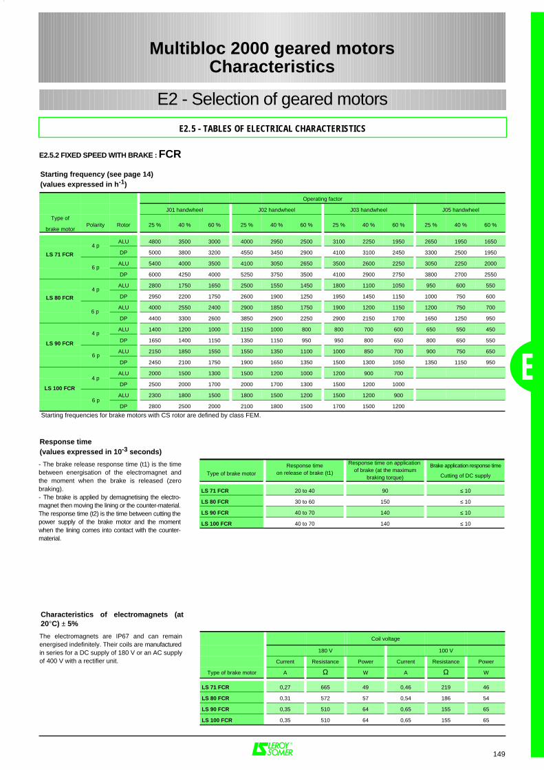
149
Operating factor
J01 handwheel J02 handwheel J03 handwheel J05 handwheel
Type of
brake motorPolarity Rotor 25 % 40 % 60 % 25 % 40 % 60 % 25 % 40 % 60 % 25 % 40 % 60 %
ALU 4800 3500 3000 4000 2950 2500 3100 2250 1950 2650 1950 1650
DP 5000 3800 3200 4550 3450 2900 4100 3100 2450 3300 2500 1950
ALU 5400 4000 3500 4100 3050 2650 3500 2600 2250 3050 2250 2000
DP 6000 4250 4000 5250 3750 3500 4100 2900 2750 3800 2700 2550
ALU 2800 1750 1650 2500 1550 1450 1800 1100 1050 950 600 550
DP 2950 2200 1750 2600 1900 1250 1950 1450 1150 1000 750 600
ALU 4000 2550 2400 2900 1850 1750 1900 1200 1150 1200 750 700
DP 4400 3300 2600 3850 2900 2250 2900 2150 1700 1650 1250 950
ALU 1400 1200 1000 1150 1000 800 800 700 600 650 550 450
DP 1650 1400 1150 1350 1150 950 950 800 650 800 650 550
ALU 2150 1850 1550 1550 1350 1100 1000 850 700 900 750 650
DP 2450 2100 1750 1900 1650 1350 1500 1300 1050 1350 1150 950
ALU 2000 1500 1300 1500 1200 1000 1200 900 700
DP 2500 2000 1700 2000 1700 1300 1500 1200 1000
ALU 2300 1800 1500 1800 1500 1200 1500 1200 900
DP 2800 2500 2000 2100 1800 1500 1700 1500 1200
Starting frequencies for brake motors with CS rotor are defined by class FEM.
LS 71 FCR
LS 80 FCR
LS 90 FCR
4 p
4 p
4 p
6 p
6 p
6 p E
E2 - Selection of geared motors
E2.5 - TABLES OF ELECTRICAL CHARACTERISTICS
Starting frequency (see page 14)(values expressed in h-1)
Response time(values expressed in 10-3 seconds)
Type of brake motor
Response timeon release of brake (t1)
Response time on applicationof brake (at the maximum
braking torque)
Brake application response time
Cutting of DC supply
LS 71 FCR 20 to 40 90 ≤ 10
LS 80 FCR 30 to 60 150 ≤ 10
LS 90 FCR 40 to 70 140 ≤ 10
LS 100 FCR 40 to 70 140 ≤ 10
Multibloc 2000 geared motorsCharacteristics
E2.5.2 FIXED SPEED WITH BRAKE : FCR
Coil voltage
180 V 100 V
Current Resistance Power Current Resistance Power
Type of brake motor A Ω W A Ω W
LS 71 FCR 0,27 665 49 0,46 219 46
LS 80 FCR 0,31 572 57 0,54 186 54
LS 90 FCR 0,35 510 64 0,65 155 65
LS 100 FCR 0,35 510 64 0,65 155 65
Characteristics of electromagnets (at20°C) ± 5%
- The brake release response time (t1) is the timebetween energisation of the electromagnet andthe moment when the brake is released (zerobraking).- The brake is applied by demagnetising the electro-magnet then moving the lining or the counter-material.The response time (t2) is the time between cutting thepower supply of the brake motor and the momentwhen the lining comes into contact with the counter-material.
The electromagnets are IP67 and can remainenergised indefinitely. Their coils are manufacturedin series for a DC supply of 180 V or an AC supplyof 400 V with a rectifier unit.
LS 100 FCR
4 p
6 p
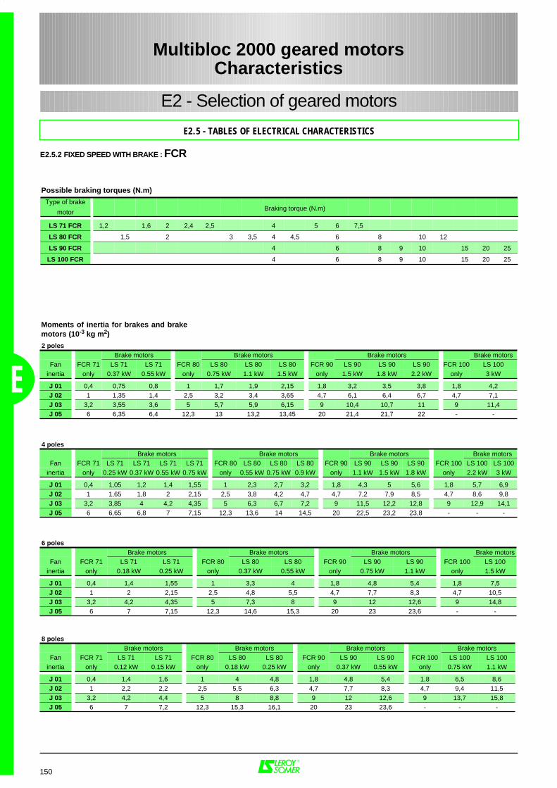
150
E2 - Selection of geared motors
E2.5 - TABLES OF ELECTRICAL CHARACTERISTICS
Possible braking torques (N.m)
Moments of inertia for brakes and brakemotors (10-3 kg m2)
Multibloc 2000 geared motorsCharacteristics
E
E2.5.2 FIXED SPEED WITH BRAKE : FCR
Type of brake
motorBraking torque (N.m)
LS 71 FCR 1,2 1,6 2 2,4 2,5 4 5 6 7,5
LS 80 FCR 1,5 2 3 3,5 4 4,5 6 8 10 12
LS 90 FCR 4 6 8 9 10 15 20 25
LS 100 FCR 4 6 8 9 10 15 20 25
2 poles Brake motors Brake motors Brake motors Brake motors
Fan FCR 71 LS 71 LS 71 FCR 80 LS 80 LS 80 LS 80 FCR 90 LS 90 LS 90 LS 90 FCR 100 LS 100inertia only 0.37 kW 0.55 kW only 0.75 kW 1.1 kW 1.5 kW only 1.5 kW 1.8 kW 2.2 kW only 3 kW
J 01 0,4 0,75 0,8 1 1,7 1,9 2,15 1,8 3,2 3,5 3,8 1,8 4,2J 02 1 1,35 1,4 2,5 3,2 3,4 3,65 4,7 6,1 6,4 6,7 4,7 7,1J 03 3,2 3,55 3,6 5 5,7 5,9 6,15 9 10,4 10,7 11 9 11,4J 05 6 6,35 6,4 12,3 13 13,2 13,45 20 21,4 21,7 22 - -
4 poles Brake motors Brake motors Brake motors Brake motors
Fan FCR 71 LS 71 LS 71 LS 71 LS 71 FCR 80 LS 80 LS 80 LS 80 FCR 90 LS 90 LS 90 LS 90 FCR 100 LS 100 LS 100inertia only 0.25 kW 0.37 kW 0.55 kW 0.75 kW only 0.55 kW 0.75 kW 0.9 kW only 1.1 kW 1.5 kW 1.8 kW only 2.2 kW 3 kW
J 01 0,4 1,05 1,2 1,4 1,55 1 2,3 2,7 3,2 1,8 4,3 5 5,6 1,8 5,7 6,9J 02 1 1,65 1,8 2 2,15 2,5 3,8 4,2 4,7 4,7 7,2 7,9 8,5 4,7 8,6 9,8J 03 3,2 3,85 4 4,2 4,35 5 6,3 6,7 7,2 9 11,5 12,2 12,8 9 12,9 14,1J 05 6 6,65 6,8 7 7,15 12,3 13,6 14 14,5 20 22,5 23,2 23,8 - - -
6 poles Brake motors Brake motors Brake motors Brake motors
Fan FCR 71 LS 71 LS 71 FCR 80 LS 80 LS 80 FCR 90 LS 90 LS 90 FCR 100 LS 100inertia only 0.18 kW 0.25 kW only 0.37 kW 0.55 kW only 0.75 kW 1.1 kW only 1.5 kW
J 01 0,4 1,4 1,55 1 3,3 4 1,8 4,8 5,4 1,8 7,5J 02 1 2 2,15 2,5 4,8 5,5 4,7 7,7 8,3 4,7 10,5J 03 3,2 4,2 4,35 5 7,3 8 9 12 12,6 9 14,8J 05 6 7 7,15 12,3 14,6 15,3 20 23 23,6 - -
8 poles Brake motors Brake motors Brake motors Brake motors
Fan FCR 71 LS 71 LS 71 FCR 80 LS 80 LS 80 FCR 90 LS 90 LS 90 FCR 100 LS 100 LS 100inertia only 0.12 kW 0.15 kW only 0.18 kW 0.25 kW only 0.37 kW 0.55 kW only 0.75 kW 1.1 kW
J 01 0,4 1,4 1,6 1 4 4,8 1,8 4,8 5,4 1,8 6,5 8,6J 02 1 2,2 2,2 2,5 5,5 6,3 4,7 7,7 8,3 4,7 9,4 11,5J 03 3,2 4,2 4,4 5 8 8,8 9 12 12,6 9 13,7 15,8J 05 6 7 7,2 12,3 15,3 16,1 20 23 23,6 - - -
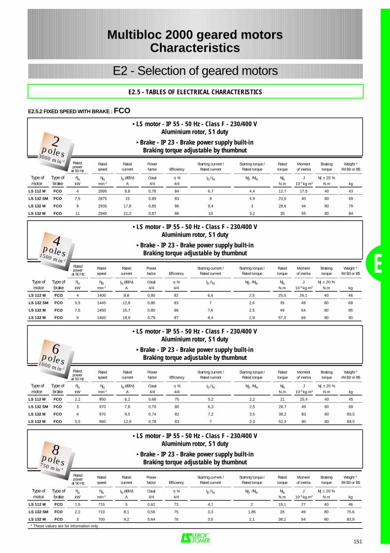
151
Rated Rated Power Starting current / Starting torque / Rated Moment Braking Weight *speed current factor Efficiency Rated current Rated torque torque of inertia torque IM B3 or B5
Type of Type of PN NN IN (400 V) Cos ϕ η % ID / IN MD / MN MN J Mf ± 20 % motor brake kW min-1 A 4/4 4/4 N.m 10-3 kg.m2 N.m kg
LS 112 M FCO 4 2895 8,8 0,78 84 6,7 4,4 12,7 17,5 40 43
LS 132 SM FCO 7,5 2875 15 0,89 83 8 4,9 23,9 40 80 69
LS 132 M FCO 9 2935 17,8 0,85 86 8,4 3 28,6 44 80 79
LS 132 M FCO 11 2940 21,2 0,87 86 10 3,2 35 55 80 84
Ratedpower
at 50 Hz
E
E2 - Selection of geared motors
E2.5 - TABLES OF ELECTRICAL CHARACTERISTICS
Rated Rated Power Starting current / Starting torque / Rated Moment Braking Weight *speed current factor Efficiency Rated current Rated torque torque of inertia torque IM B3 or B5
Type of Type of PN NN IN (400 V) Cos ϕ η % ID / IN MD / MN MN J Mf ± 20 % motor brake kW min-1 A 4/4 4/4 N.m 10-3 kg.m2 N.m kg
LS 112 M FCO 4 1400 8,8 0,80 82 6,6 2,5 25,5 26,1 40 46
LS 132 SM FCO 5,5 1445 12,8 0,80 83 7 2,6 35 49 80 69
LS 132 M FCO 7,5 1450 15,7 0,80 86 7,6 2,5 49 64 80 85
LS 132 M FCO 9 1460 18,9 0,79 87 8,4 2,9 57,3 69 80 90
• LS motor - IP 55 - 50 Hz - Class F - 230/400 VAluminium rotor, S1 duty
• Brake - IP 23 - Brake power supply built-inBraking torque adjustable by thumbnut
Ratedpower
at 50 Hz
Multibloc 2000 geared motorsCharacteristics
E2.5.2 FIXED SPEED WITH BRAKE : FCO
* These values are for information only
• LS motor - IP 55 - 50 Hz - Class F - 230/400 VAluminium rotor, S1 duty
• Brake - IP 23 - Brake power supply built-inBraking torque adjustable by thumbnut
2Pôles3000 min-1
2poles3000 min-1
2Pôles3000 min-1
4poles1500 min-1
Rated Rated Power Starting current / Starting torque / Rated Moment Braking Weight *speed current factor Efficiency Rated current Rated torque torque of inertia torque IM B3 or B5
Type of Type of PN NN IN (400 V) Cos ϕ η % ID / IN MD / MN MN J Mf ± 20 % motor brake kW min-1 A 4/4 4/4 N.m 10-3 kg.m2 N.m kg
LS 112 M FCO 2,2 950 6,2 0,68 75 5,2 2,2 21 25,4 40 45
LS 132 SM FCO 3 970 7,8 0,70 80 6,3 2,5 28,7 49 80 69
LS 132 M FCO 4 970 9,5 0,74 82 7,2 3,5 38,2 83 80 83,5
LS 132 M FCO 5,5 960 12,9 0,78 83 7 2,3 52,3 90 80 89,5
Ratedpower
at 50 Hz
• LS motor - IP 55 - 50 Hz - Class F - 230/400 VAluminium rotor, S1 duty
• Brake - IP 23 - Brake power supply built-inBraking torque adjustable by thumbnut
2Pôles3000 min-1
6poles1000 min-1
Rated Rated Power Starting current / Starting torque / Rated Moment Braking Weight *speed current factor Efficiency Rated current Rated torque torque of inertia torque IM B3 or B5
Type of Type of PN NN IN (400 V) Cos ϕ η % ID / IN MD / MN MN J Mf ± 20 % motor brake kW min-1 A 4/4 4/4 N.m 10-3 kg.m2 N.m kg
LS 112 M FCO 1,5 715 5 0,62 73 4,1 2 19,1 27 40 46
LS 132 SM FCO 2,2 710 8,1 0,55 75 3,3 1,85 28 49 80 75,6
LS 132 M FCO 3 700 9,2 0,64 76 3,5 2,1 38,2 64 80 83,9
• LS motor - IP 55 - 50 Hz - Class F - 230/400 VAluminium rotor, S1 duty
• Brake - IP 23 - Brake power supply built-inBraking torque adjustable by thumbnut
Ratedpower
at 50 Hz
2Pôles3000 min-1
8poles750 min-1
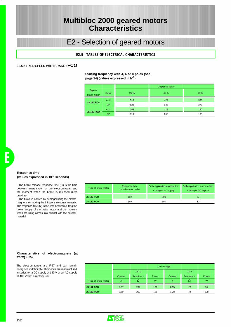
152
E2 - Selection of geared motors
E2.5 - TABLES OF ELECTRICAL CHARACTERISTICS
Starting frequency with 4, 6 or 8 poles (seepage 14) (values expressed in h-1)
Response time(values expressed in 10-3 seconds)
Multibloc 2000 geared motorsCharacteristics
E
E2.5.2 FIXED SPEED WITH BRAKE : FCO
Characteristics of electromagnets (at20°C) ± 5%
- The brake release response time (t1) is the timebetween energisation of the electromagnet andthe moment when the brake is released (zerobraking).- The brake is applied by demagnetising the electro-magnet then moving the lining or the counter-material.The response time (t2) is the time between cutting thepower supply of the brake motor and the momentwhen the lining comes into contact with the counter-material.
The electromagnets are IP67 and can remainenergised indefinitely. Their coils are manufacturedin series for a DC supply of 180 V or an AC supplyof 400 V with a rectifier unit.
Operating factor
Type of
brake motorRotor 25 % 40 % 60 %
ALU 510 429 300
DP 638 536 375
ALU 255 215 150
DP 319 268 188
LS 112 FCO
LS 132 FCO
Type of brake motorResponse time
on release of brakeBrake application response time
Cutting of AC supply
Brake application response time
Cutting of DC supply
LS 112 FCO 180 380 23
LS 132 FCO 260 590 30
Coil voltage
180 V 100 V
Current Resistance Power Current Resistance Power
Type of brake motor A Ω W A Ω W
LS 112 FCO 0,67 269 120 0,55 183 55
LS 132 FCO 0,69 260 125 1,28 78 128
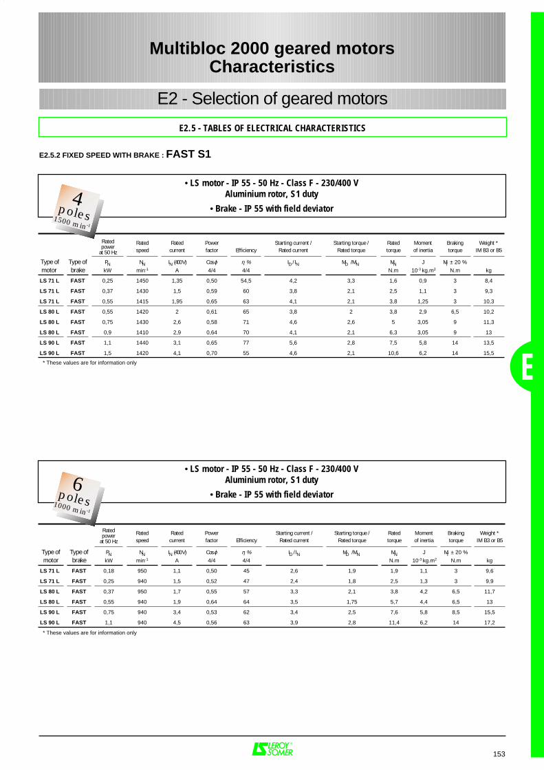
153
Rated Rated Power Starting current / Starting torque / Rated Moment Braking Weight *speed current factor Efficiency Rated current Rated torque torque of inertia torque IM B3 or B5
Type of Type of PN NN IN (400 V) Cos ϕ η % ID / IN MD / MN MN J Mf ± 20 % motor brake kW min-1 A 4/4 4/4 N.m 10-3 kg.m2 N.m kg
LS 71 L FAST 0,25 1450 1,35 0,50 54,5 4,2 3,3 1,6 0,9 3 8,4
LS 71 L FAST 0,37 1430 1,5 0,59 60 3,8 2,1 2,5 1,1 3 9,3
LS 71 L FAST 0,55 1415 1,95 0,65 63 4,1 2,1 3,8 1,25 3 10,3
LS 80 L FAST 0,55 1420 2 0,61 65 3,8 2 3,8 2,9 6,5 10,2
LS 80 L FAST 0,75 1430 2,6 0,58 71 4,6 2,6 5 3,05 9 11,3
LS 80 L FAST 0,9 1410 2,9 0,64 70 4,1 2,1 6,3 3,05 9 13
LS 90 L FAST 1,1 1440 3,1 0,65 77 5,6 2,8 7,5 5,8 14 13,5
LS 90 L FAST 1,5 1420 4,1 0,70 55 4,6 2,1 10,6 6,2 14 15,5
Ratedpower
at 50 Hz
E
E2 - Selection of geared motors
E2.5 - TABLES OF ELECTRICAL CHARACTERISTICS
Rated Rated Power Starting current / Starting torque / Rated Moment Braking Weight *speed current factor Efficiency Rated current Rated torque torque of inertia torque IM B3 or B5
Type of Type of PN NN IN (400 V) Cos ϕ η % ID / IN MD / MN MN J Mf ± 20 % motor brake kW min-1 A 4/4 4/4 N.m 10-3 kg.m2 N.m kg
LS 71 L FAST 0,18 950 1,1 0,50 45 2,6 1,9 1,9 1,1 3 9,6
LS 71 L FAST 0,25 940 1,5 0,52 47 2,4 1,8 2,5 1,3 3 9,9
LS 80 L FAST 0,37 950 1,7 0,55 57 3,3 2,1 3,8 4,2 6,5 11,7
LS 80 L FAST 0,55 940 1,9 0,64 64 3,5 1,75 5,7 4,4 6,5 13
LS 90 L FAST 0,75 940 3,4 0,53 62 3,4 2,5 7,6 5,8 8,5 15,5
LS 90 L FAST 1,1 940 4,5 0,56 63 3,9 2,8 11,4 6,2 14 17,2
Ratedpower
at 50 Hz
Multibloc 2000 geared motorsCharacteristics
E2.5.2 FIXED SPEED WITH BRAKE : FAST S1
* These values are for information only
• LS motor - IP 55 - 50 Hz - Class F - 230/400 VAluminium rotor, S1 duty
• Brake - IP 55 with field deviator2
Pôles3000 min-1
4poles1500 min-1
* These values are for information only
• LS motor - IP 55 - 50 Hz - Class F - 230/400 VAluminium rotor, S1 duty
• Brake - IP 55 with field deviator2
Pôles3000 min-1
6poles1000 min-1
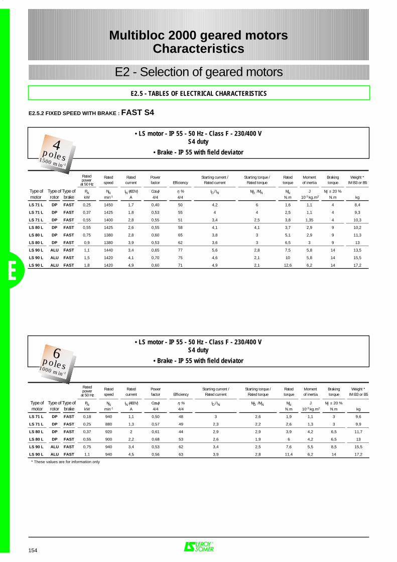
154
Rated Rated Power Starting current / Starting torque / Rated Moment Braking Weight *speed current factor Efficiency Rated current Rated torque torque of inertia torque IM B3 or B5
Type of Type of Type of PN NN IN (400 V) Cos ϕ η % ID / IN MD / MN MN J Mf ± 20 % motor rotor brake kW min-1 A 4/4 4/4 N.m 10-3 kg.m2 N.m kg
LS 71 L DP FAST 0,25 1450 1,7 0,40 50 4,2 6 1,6 1,1 4 8,4
LS 71 L DP FAST 0,37 1425 1,8 0,53 55 4 4 2,5 1,1 4 9,3
LS 71 L DP FAST 0,55 1400 2,8 0,55 51 3,4 2,5 3,8 1,35 4 10,3
LS 80 L DP FAST 0,55 1425 2,6 0,55 58 4,1 4,1 3,7 2,9 9 10,2
LS 80 L DP FAST 0,75 1380 2,8 0,60 65 3,8 3 5,1 2,9 9 11,3
LS 80 L DP FAST 0,9 1380 3,9 0,53 62 3,6 3 6,5 3 9 13
LS 90 L ALU FAST 1,1 1440 3,4 0,65 77 5,6 2,8 7,5 5,8 14 13,5
LS 90 L ALU FAST 1,5 1420 4,1 0,70 75 4,6 2,1 10 5,8 14 15,5
LS 90 L ALU FAST 1,8 1420 4,9 0,60 71 4,9 2,1 12,6 6,2 14 17,2
Ratedpower
at 50 Hz
E2 - Selection of geared motors
E2.5 - TABLES OF ELECTRICAL CHARACTERISTICS
Rated Rated Power Starting current / Starting torque / Rated Moment Braking Weight *speed current factor Efficiency Rated current Rated torque torque of inertia torque IM B3 or B5
Type of Type of Type of PN NN IN (400 V) Cos ϕ η % ID / IN MD / MN MN J Mf ± 20 % motor rotor brake kW min-1 A 4/4 4/4 N.m 10-3 kg.m2 N.m kg
LS 71 L DP FAST 0,18 940 1,1 0,50 48 3 2,6 1,9 1,1 3 9,6
LS 71 L DP FAST 0,25 880 1,3 0,57 49 2,3 2,2 2,6 1,3 3 9,9
LS 80 L DP FAST 0,37 920 2 0,61 44 2,9 2,9 3,9 4,2 6,5 11,7
LS 80 L DP FAST 0,55 900 2,2 0,68 53 2,6 1,9 6 4,2 6,5 13
LS 90 L ALU FAST 0,75 940 3,4 0,53 62 3,4 2,5 7,6 5,5 8,5 15,5
LS 90 L ALU FAST 1,1 940 4,5 0,56 63 3,9 2,8 11,4 6,2 14 17,2
Ratedpower
at 50 Hz
Multibloc 2000 geared motorsCharacteristics
E
E2.5.2 FIXED SPEED WITH BRAKE : FAST S4
* These values are for information only
• LS motor - IP 55 - 50 Hz - Class F - 230/400 VS4 duty
• Brake - IP 55 with field deviator2
Pôles3000 min-1
4poles1500 min-1
• LS motor - IP 55 - 50 Hz - Class F - 230/400 VS4 duty
• Brake - IP 55 with field deviator2
Pôles3000 min-1
6poles1000 min-1
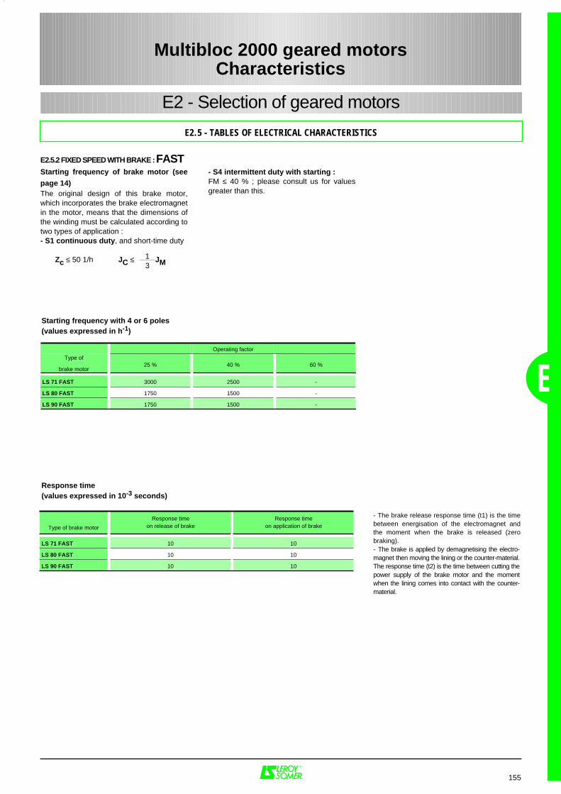
155
Operating factor
Type of
brake motor25 % 40 % 60 %
LS 71 FAST 3000 2500 -
LS 80 FAST 1750 1500 -
LS 90 FAST 1750 1500 -
E
E2 - Selection of geared motors
E2.5 - TABLES OF ELECTRICAL CHARACTERISTICS
Starting frequency with 4 or 6 poles(values expressed in h-1)
Response time(values expressed in 10-3 seconds)
Type of brake motor
Response timeon release of brake
Response timeon application of brake
LS 71 FAST 10 10
LS 80 FAST 10 10
LS 90 FAST 10 10
Multibloc 2000 geared motorsCharacteristics
E2.5.2 FIXED SPEED WITH BRAKE : FASTStarting frequency of brake motor (see
page 14)The original design of this brake motor,which incorporates the brake electromagnetin the motor, means that the dimensions ofthe winding must be calculated according totwo types of application :- S1 continuous duty, and short-time duty
Zc ≤ 50 1/h JC ≤ JM13
- S4 intermittent duty with starting :FM ≤ 40 % ; please consult us for valuesgreater than this.
- The brake release response time (t1) is the timebetween energisation of the electromagnet andthe moment when the brake is released (zerobraking).- The brake is applied by demagnetising the electro-magnet then moving the lining or the counter-material.The response time (t2) is the time between cutting thepower supply of the brake motor and the momentwhen the lining comes into contact with the counter-material.
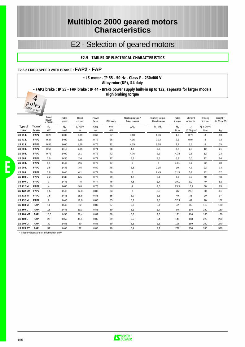
156
Rated Rated Power Starting current / Starting torque / Rated Moment Braking Weight *speed current factor Efficiency Rated current Rated torque torque of inertia torque IM B3 or B5
Type of Type of PN NN IN (400 V) Cos ϕ η % ID / IN MD / MN MN J Mf ± 20 % motor brake kW min-1 A 4/4 4/4 N.m 10-3 kg.m2 N.m kg
LS 71 L FAP2 0,25 1430 0,79 0,63 57 3,98 1,76 1,7 0,75 8 13
LS 71 L FAP2 0,37 1400 1,16 0,72 66 4,05 2,12 2,5 0,94 8 13
LS 71 L FAP2 0,55 1400 1,56 0,75 72 4,15 2,28 3,7 1,2 8 15
LS 80 L FAP2 0,55 1410 1,65 0,71 68 4,3 2,5 3,5 2,4 12 21
LS 80 L FAP2 0,75 1400 2,1 0,75 72 4,76 2,6 4,78 2,8 12 23
LS 80 L FAP2 0,9 1430 2,4 0,71 77 5,5 3,6 6,2 3,3 12 24
LS 90 L FAP2 1,1 1440 2,6 0,79 77 5 2 7,01 4,2 22 30
LS 90 L FAP2 1,5 1435 3,5 0,80 78 5,3 2,15 10 4,9 22 33
LS 90 L FAP2 1,8 1440 4,1 0,79 80 6 2,45 11,5 5,9 22 37
LS 100 L FAP2 2,2 1435 5,5 0,73 79 4,2 2,1 14 7,7 40 48
LS 100 L FAP2 3 1435 7,5 0,74 75 4,3 2,4 19,1 9,2 40 52
LS 112 M FAP2 4 1400 9,6 0,78 80 4 2,5 25,5 15,2 60 63
LS 132 SM FAP2 5,5 1445 12,8 0,80 83 7 2,6 35 23,6 90 81
LS 132 M FAP2 7,5 1445 15,8 0,85 85 6,9 2,6 49 36 90 97
LS 132 M FAP2 9 1445 18,6 0,86 85 8,2 2,8 57,3 41 90 102
LS 160 M FAP 11 1440 22 0,87 87 5,3 2,1 72 82 110 130
LS 160 L FAP 15 1445 29,3 0,86 89 6,2 2,7 98 104 150 150
LS 180 MT FAP 18,5 1450 36,4 0,87 88 5,8 2,5 121 116 180 150
LS 180 L FAP 22 1455 44,1 0,85 89 5,5 2,4 144 158 220 200
LS 200 LT FAP 30 1455 60 0,85 89 6,3 2,5 196 189 290 240
LS 225 ST FAP 37 1460 72 0,86 90 6,4 2,7 239 330 390 320
Ratedpower
at 50 Hz
E2 - Selection of geared motors
E2.5 - TABLES OF ELECTRICAL CHARACTERISTICS
Multibloc 2000 geared motorsCharacteristics
E
E2.5.2 FIXED SPEED WITH BRAKE : FAP2 - FAP
* These values are for information only
• LS motor - IP 55 - 50 Hz - Class F - 230/400 VAlloy rotor (DP), S4 duty
• FAP2 brake : IP 55 - FAP brake : IP 44 - Brake power supply built-in up to 132, separate for larger modelsHigh braking torque2
Pôles3000 min-1
4poles1500 min-1
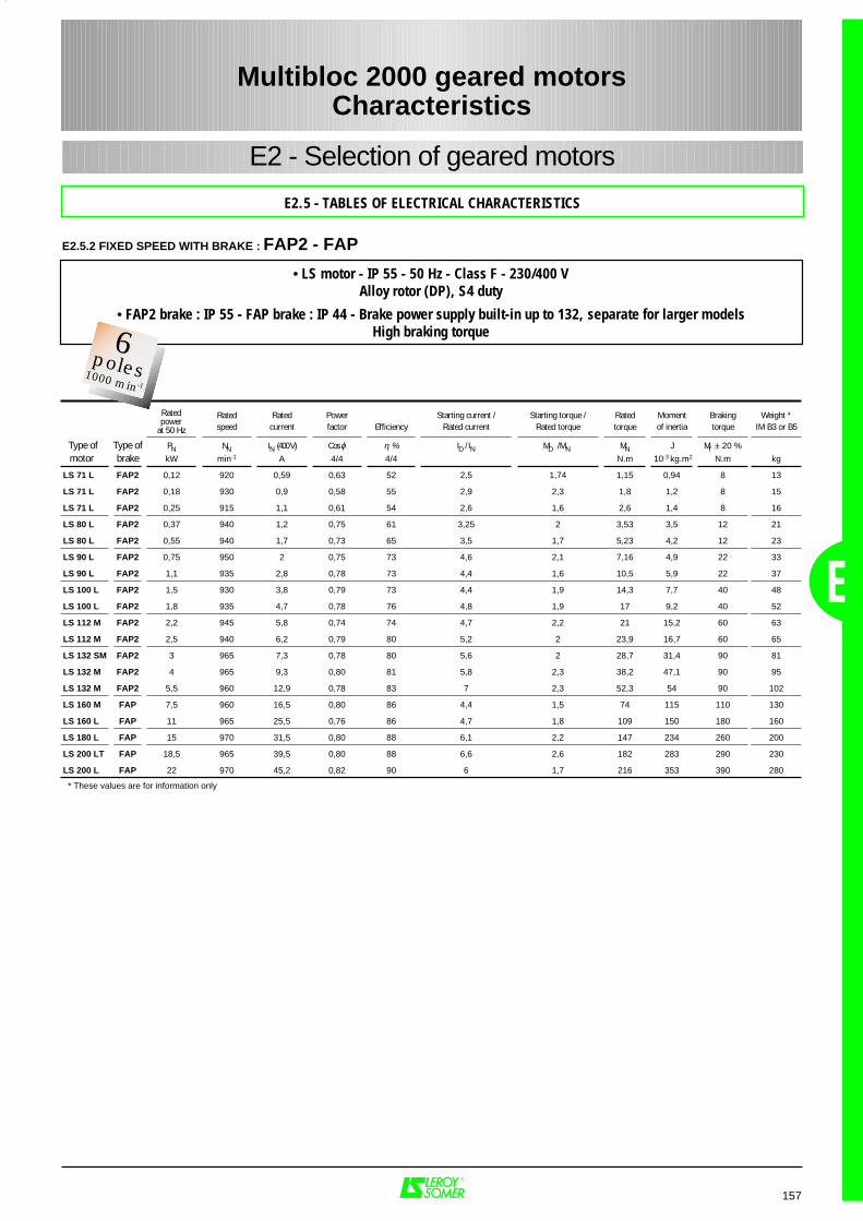
157
Rated Rated Power Starting current / Starting torque / Rated Moment Braking Weight *speed current factor Efficiency Rated current Rated torque torque of inertia torque IM B3 or B5
Type of Type of PN NN IN (400 V) Cos ϕ η % ID / IN MD / MN MN J Mf ± 20 % motor brake kW min-1 A 4/4 4/4 N.m 10-3 kg.m2 N.m kg
LS 71 L FAP2 0,12 920 0,59 0,63 52 2,5 1,74 1,15 0,94 8 13
LS 71 L FAP2 0,18 930 0,9 0,58 55 2,9 2,3 1,8 1,2 8 15
LS 71 L FAP2 0,25 915 1,1 0,61 54 2,6 1,6 2,6 1,4 8 16
LS 80 L FAP2 0,37 940 1,2 0,75 61 3,25 2 3,53 3,5 12 21
LS 80 L FAP2 0,55 940 1,7 0,73 65 3,5 1,7 5,23 4,2 12 23
LS 90 L FAP2 0,75 950 2 0,75 73 4,6 2,1 7,16 4,9 22 33
LS 90 L FAP2 1,1 935 2,8 0,78 73 4,4 1,6 10,5 5,9 22 37
LS 100 L FAP2 1,5 930 3,8 0,79 73 4,4 1,9 14,3 7,7 40 48
LS 100 L FAP2 1,8 935 4,7 0,78 76 4,8 1,9 17 9,2 40 52
LS 112 M FAP2 2,2 945 5,8 0,74 74 4,7 2,2 21 15,2 60 63
LS 112 M FAP2 2,5 940 6,2 0,79 80 5,2 2 23,9 16,7 60 65
LS 132 SM FAP2 3 965 7,3 0,78 80 5,6 2 28,7 31,4 90 81
LS 132 M FAP2 4 965 9,3 0,80 81 5,8 2,3 38,2 47,1 90 95
LS 132 M FAP2 5,5 960 12,9 0,78 83 7 2,3 52,3 54 90 102
LS 160 M FAP 7,5 960 16,5 0,80 86 4,4 1,5 74 115 110 130
LS 160 L FAP 11 965 25,5 0,76 86 4,7 1,8 109 150 180 160
LS 180 L FAP 15 970 31,5 0,80 88 6,1 2,2 147 234 260 200
LS 200 LT FAP 18,5 965 39,5 0,80 88 6,6 2,6 182 283 290 230
LS 200 L FAP 22 970 45,2 0,82 90 6 1,7 216 353 390 280
Ratedpower
at 50 Hz
E
E2 - Selection of geared motors
E2.5 - TABLES OF ELECTRICAL CHARACTERISTICS
Multibloc 2000 geared motorsCharacteristics
E2.5.2 FIXED SPEED WITH BRAKE : FAP2 - FAP
* These values are for information only
• LS motor - IP 55 - 50 Hz - Class F - 230/400 VAlloy rotor (DP), S4 duty
• FAP2 brake : IP 55 - FAP brake : IP 44 - Brake power supply built-in up to 132, separate for larger modelsHigh braking torque2
Pôles3000 min-1
6poles1000 min-1
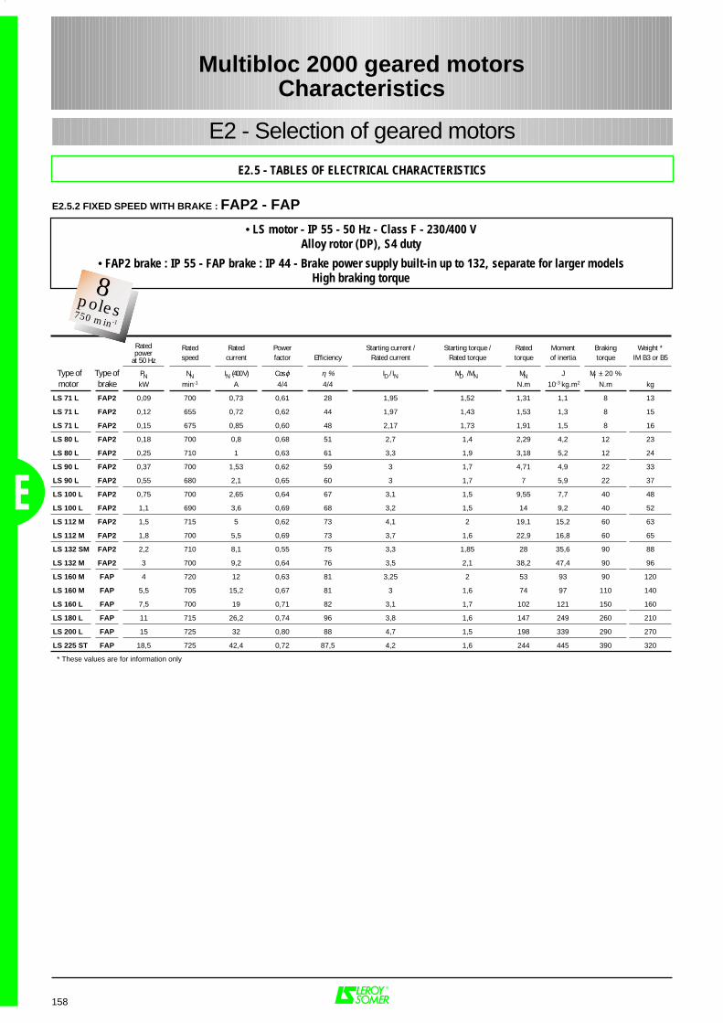
158
Rated Rated Power Starting current / Starting torque / Rated Moment Braking Weight *speed current factor Efficiency Rated current Rated torque torque of inertia torque IM B3 or B5
Type of Type of PN NN IN (400 V) Cos ϕ η % ID / IN MD / MN MN J Mf ± 20 % motor brake kW min-1 A 4/4 4/4 N.m 10-3 kg.m2 N.m kg
LS 71 L FAP2 0,09 700 0,73 0,61 28 1,95 1,52 1,31 1,1 8 13
LS 71 L FAP2 0,12 655 0,72 0,62 44 1,97 1,43 1,53 1,3 8 15
LS 71 L FAP2 0,15 675 0,85 0,60 48 2,17 1,73 1,91 1,5 8 16
LS 80 L FAP2 0,18 700 0,8 0,68 51 2,7 1,4 2,29 4,2 12 23
LS 80 L FAP2 0,25 710 1 0,63 61 3,3 1,9 3,18 5,2 12 24
LS 90 L FAP2 0,37 700 1,53 0,62 59 3 1,7 4,71 4,9 22 33
LS 90 L FAP2 0,55 680 2,1 0,65 60 3 1,7 7 5,9 22 37
LS 100 L FAP2 0,75 700 2,65 0,64 67 3,1 1,5 9,55 7,7 40 48
LS 100 L FAP2 1,1 690 3,6 0,69 68 3,2 1,5 14 9,2 40 52
LS 112 M FAP2 1,5 715 5 0,62 73 4,1 2 19,1 15,2 60 63
LS 112 M FAP2 1,8 700 5,5 0,69 73 3,7 1,6 22,9 16,8 60 65
LS 132 SM FAP2 2,2 710 8,1 0,55 75 3,3 1,85 28 35,6 90 88
LS 132 M FAP2 3 700 9,2 0,64 76 3,5 2,1 38,2 47,4 90 96
LS 160 M FAP 4 720 12 0,63 81 3,25 2 53 93 90 120
LS 160 M FAP 5,5 705 15,2 0,67 81 3 1,6 74 97 110 140
LS 160 L FAP 7,5 700 19 0,71 82 3,1 1,7 102 121 150 160
LS 180 L FAP 11 715 26,2 0,74 96 3,8 1,6 147 249 260 210
LS 200 L FAP 15 725 32 0,80 88 4,7 1,5 198 339 290 270
LS 225 ST FAP 18,5 725 42,4 0,72 87,5 4,2 1,6 244 445 390 320
Ratedpower
at 50 Hz
E2 - Selection of geared motors
E2.5 - TABLES OF ELECTRICAL CHARACTERISTICS
Multibloc 2000 geared motorsCharacteristics
E
E2.5.2 FIXED SPEED WITH BRAKE : FAP2 - FAP
* These values are for information only
• LS motor - IP 55 - 50 Hz - Class F - 230/400 VAlloy rotor (DP), S4 duty
• FAP2 brake : IP 55 - FAP brake : IP 44 - Brake power supply built-in up to 132, separate for larger modelsHigh braking torque2
Pôles3000 min-1
8poles750 min-1
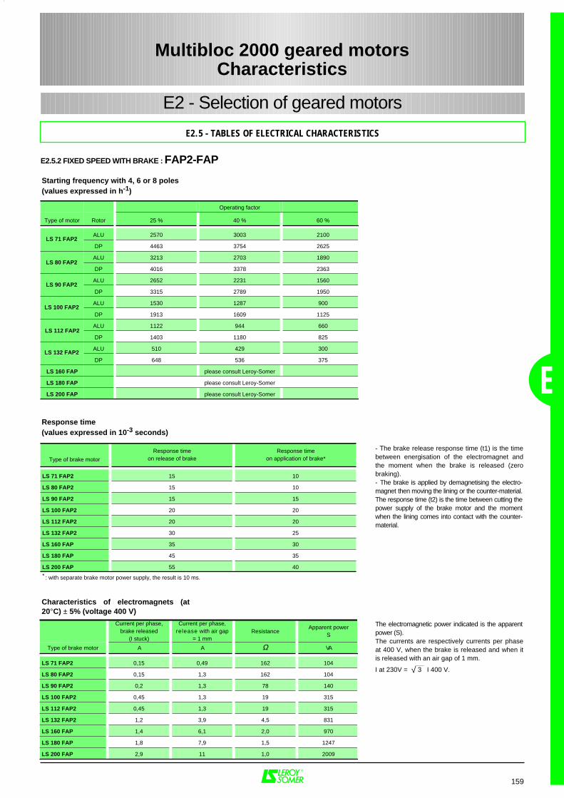
159
E
E2 - Selection of geared motors
E2.5 - TABLES OF ELECTRICAL CHARACTERISTICS
Starting frequency with 4, 6 or 8 poles(values expressed in h-1)
Response time(values expressed in 10-3 seconds)
Type of brake motor
Response timeon release of brake
Response timeon application of brake*
LS 71 FAP2 15 10
LS 80 FAP2 15 10
LS 90 FAP2 15 15
LS 100 FAP2 20 20
LS 112 FAP2 20 20
LS 132 FAP2 30 25
LS 160 FAP 35 30
LS 180 FAP 45 35
LS 200 FAP 55 40
* : with separate brake motor power supply, the result is 10 ms.
Multibloc 2000 geared motorsCharacteristics
E2.5.2 FIXED SPEED WITH BRAKE : FAP2-FAP
Current per phase,brake released
(I stuck)
Current per phase,release with air gap
= 1 mmResistance
Apparent powerS
Type of brake motor A A Ω VA
LS 71 FAP2 0,15 0,49 162 104
LS 80 FAP2 0,15 1,3 162 104
LS 90 FAP2 0,2 1,3 78 140
LS 100 FAP2 0,45 1,3 19 315
LS 112 FAP2 0,45 1,3 19 315
LS 132 FAP2 1,2 3,9 4,5 831
LS 160 FAP 1,4 6,1 2,0 970
LS 180 FAP 1,8 7,9 1,5 1247
LS 200 FAP 2,9 11 1,0 2009
Characteristics of electromagnets (at20°C) ± 5% (voltage 400 V)
- The brake release response time (t1) is the timebetween energisation of the electromagnet andthe moment when the brake is released (zerobraking).- The brake is applied by demagnetising the electro-magnet then moving the lining or the counter-material.The response time (t2) is the time between cutting thepower supply of the brake motor and the momentwhen the lining comes into contact with the counter-material.
The electromagnetic power indicated is the apparentpower (S).The currents are respectively currents per phaseat 400 V, when the brake is released and when itis released with an air gap of 1 mm.
I at 230V = √ 3 I 400 V.
Operating factor
Type of motor Rotor 25 % 40 % 60 %
ALU 2570 3003 2100
DP 4463 3754 2625
ALU 3213 2703 1890
DP 4016 3378 2363
ALU 2652 2231 1560
DP 3315 2789 1950
ALU 1530 1287 900
DP 1913 1609 1125
ALU 1122 944 660
DP 1403 1180 825
ALU 510 429 300
DP 648 536 375
LS 160 FAP please consult Leroy-Somer
LS 180 FAP please consult Leroy-Somer
LS 200 FAP please consult Leroy-Somer
LS 71 FAP2
LS 80 FAP2
LS 90 FAP2
LS 100 FAP2
LS 112 FAP2
LS 132 FAP2

160
The specific electrical characteristics of thesemotors are available on request.
In general applications, the motors are fittedwith aluminium rotors for S1 duty.In lifting applications, the motors are fitted withDP rotors and a keyed weight (optional) for S3or S4 duty (p.79).
In displacement applications, the motorsare fitted with DP rotors (p.80) for S4 dutyand the power ratings are given as anexample for replacement .
E2 - Selection of geared motors
E2.5 - TABLES OF ELECTRICAL CHARACTERISTICS
• LS motor - IP 55 - Class F
General applications (U.G.) ; Lifting applications (L.V.) ; Displacement applications (T.R.)
1 Dahlander winding (1 voltage) 2 windings (1 or 2 voltages)
2/4 poles 4/8 poles 2/4 poles 2/6 poles 2/8 poles 2/12 poles 2/16 poles 4/6 poles 4/8 poles 4/12 poles 4/16 poles
Type of Appli- PN PN PN PN PN PN PN PN PN PN PNmotor cation kW kW kW kW kW kW kW kW kW kW kW
LS 71 L UGCharacteristics
page 161 - - - - - - - - - -
UGCharacteristics
page 161 - - - - - - - - - -
UGCharacteristics
page 161 - - - - - - - - - -
UG -Characteristics
page 162 - - - - - - - - -
UG -Characteristics
page 162 - - - - - - - - -
LS 80 L UGCharacteristics
page 161Characteristics
page 162 - - - - - - - - -
LV 0.55 / 0.37 0.25 / 0.12 - - - - - - - - -
TR 0.37 / 0.25 - - - - - - - - - -
UGCharacteristics
page 161Characteristics
page 162 0.55 / 0.25 0.55 / 0.18 0.55 / 0.12 - - 0.5 / 0.33 - - -
LV 1.1 / 0.75 0.55 / 0.28 0.55 / 0.25 0.55 / 0.18 0.55 / 0.12 - - - - - -
TR 0.75 / 0.55 0.18 / 0.12 0.25 / 0.12 0.25 / 0.08 0.25 / 0.06 - - - - - -
LS 90 L UGCharacteristics
page 161Characteristics
page 162 0.75 / 0.37 0.75 / 0.24 0.75 / 0.18 0.75 / 0.12 - 0.7 / 0.45 0.65 / 0.3 0.37 / 0.12 -
LV 1.5 / 1.1 0.8 / 0.4 0.75 / 0.37 0.75 / 0.24 0.75 / 0.18 0.25 / 0.04 - 0.55 / 0.37 0.37 / 0.18 0.37 / 0.12 -
TR 1.1 / 0.75 0.25 / 0.18 0.55 / 0.27 0.55 / 0.18 0.55 / 0.14 - - 0.25 / 0.16 - - -
UGCharacteristics
page 161Characteristics
page 162 1.5 / 0.75 1.5 / 0.5 1.5 / 0.37 1.1 / 0.18 0.55 / 0.06 1.2 / 0.8 1 / 0.5 0.55 / 0.12 -
LV 2.2 / 1.5 1.2 / 0.6 1.5 / 0.75 1.1 / 0.37 1.1 / 0.33 0.55 / 0.09 0.55 / 0.06 0.9 / 0.66 0.75 / 0.37 0.55 / 0.12 -
TR 1.5 / 1.1 0.55 / 0.37 0.75 / 0.37 0.75 / 0.25 0.75 / 0.18 0.25 / 0.04 0.25 / 0.03 0.55 / 0.37 0.44 / 0.22 0.37 / 0.12 -
LS 100 L UGCharacteristics
page 161Characteristics
page 162 2.2 / 1.1 2.2 / 0.75 2.2 / 0.55 1.5 / 0.24 0.9 / 0.12 1.8 / 1.2 1.6 / 0.8 0.9 / 0.3 0.75 / 0.18
LV 3.4 / 2.7 1.8 / 1 2.2 / 1.1 2.2 / 0.75 2.2 / 0.55 1.1 / 0.18 0.9 / 0.12 1.1 / 0.75 1.1 / 0.55 0.9 / 0.3 0.75 / 0.18
TR 2.2 / 1.5 0.75 / 0.55 1.5 / 0.75 1.5 / 0.48 1.5 / 0.37 0.55 / 0.09 0.55 / 0.07 0.75 / 0.48 0.55 / 0.27 0.55 / 0.18 0.37 / 0.09
LS 112 M UGCharacteristics
page 161Characteristics
page 162 3.3 / 1.7 3 / 1 3 / 0.75 2.2 / 0.37 1.1 / 0.15 2.2 / 1.5 1.8 / 0.9 1.1 / 0.37 1.1 / 0.27
LV 5 / 3.7 3 / 1.5 3.3 / 1.7 2.5 / 0.85 3 / 0.75 1.8 / 0.3 1.1 / 0.15 2.2 / 1.5 1.5 / 0.75 1.1 / 0.37 1.1 / 0.27
TR 3.5 / 2.5 1.5 / 1.1 2.2 / 1.1 2.2 / 0.75 2.2 / 0.55 1.1 / 0.25 0.75 / 0.09 1.8 / 1.1 1.3 / 0.6 1.1 / 0.37 0.75 / 0.18
LS 132 SM UGCharacteristics
page 161 5.5 / 2.75 4 / 2 4.4 / 1.5 4.4 / 1.1 4 / 0.6 - 3.6 / 2.4 3.8 / 1.9 2.6 / 0.9 1.8 / 0.44
LV 6 / 4.8 5.5 / 2.75 4 / 2 4 / 1.3 4 / 1 3.3 / 0.5 - 2.6 / 2.2 3 / 1.45 2.6 / 0.9 1.8 / 0.44
TR 4.4 / 3 3 / 1.9 - 3 / 1 3 / 0.75 2.6 / 0.4 - 2.2 / 1.5 2.2 / 1.1 1.8 / 0.65 1.5 / 0.37
LS 132 M UGCharacteristics
page 161Characteristics
page 162 6 / 3 6.5 / 2.2 6.5 / 1.6 6 / 0.9 3 / 0.37 5.5 / 3.7 5.5 / 2.75 3.7 / 1.3 3 / 0.75
LV 8.5 / 6.5 8 / 4 6 / 3 6 / 2 6 / 1.5 5 / 0.8 3 / 0.37 4 / 2.8 4.4 / 2.2 3.7 / 1.3 3 / 0.75
TR 5 / 3.3 5 / 3.3 2.6 / 1.3 4.4 / 1.5 4.4 / 1.1 4 / 0.66 3 / 0.37 3 / 2.2 3 / 1.5 2.5 / 0.85 2.2 / 0.55
MAINS SUPPLY 400 V 50 Hz
Multibloc 2000 geared motorsCharacteristics
E
E2.5.2 FIXED SPEED WITH BRAKEGeneral table of two-speed brake motors
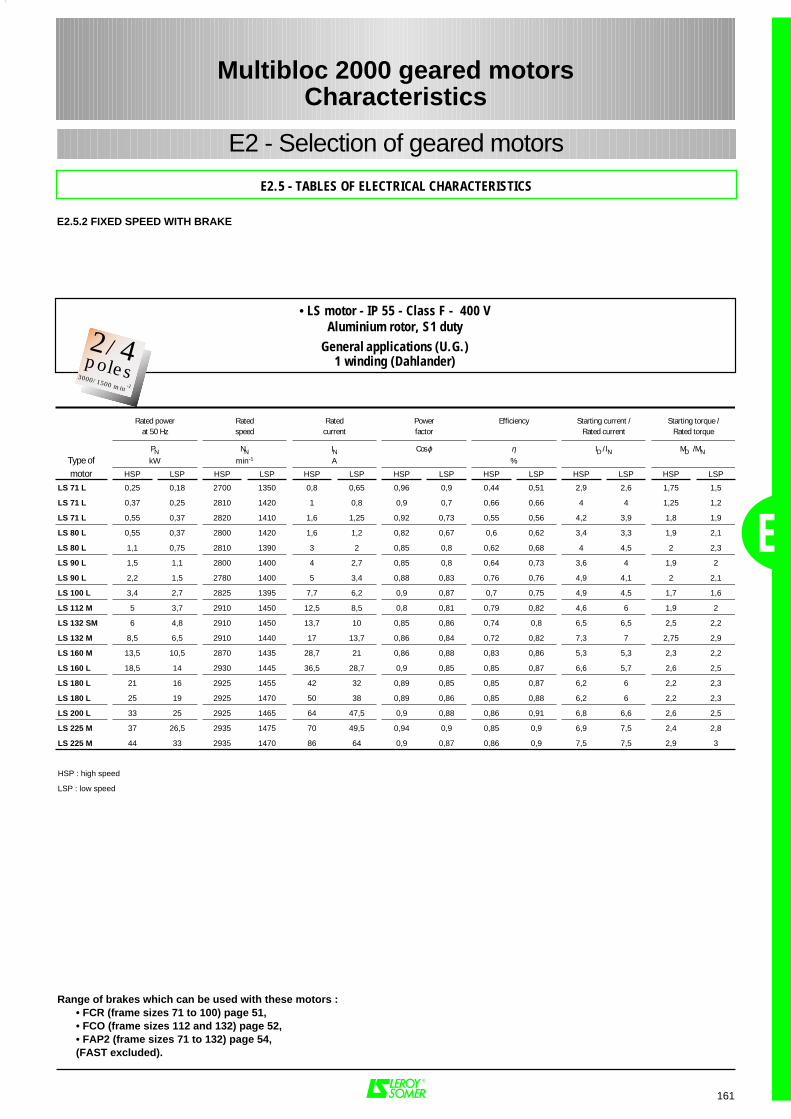
161
Rated power Rated Rated Power Efficiency Starting current / Starting torque /at 50 Hz speed current factor Rated current Rated torque
PN NN IN Cos ϕ η ID / IN MD / MN Type of kW min-1 A %
motor HSP LSP HSP LSP HSP LSP HSP LSP HSP LSP HSP LSP HSP LSP
LS 71 L 0,25 0,18 2700 1350 0,8 0,65 0,96 0,9 0,44 0,51 2,9 2,6 1,75 1,5
LS 71 L 0,37 0,25 2810 1420 1 0,8 0,9 0,7 0,66 0,66 4 4 1,25 1,2
LS 71 L 0,55 0,37 2820 1410 1,6 1,25 0,92 0,73 0,55 0,56 4,2 3,9 1,8 1,9
LS 80 L 0,55 0,37 2800 1420 1,6 1,2 0,82 0,67 0,6 0,62 3,4 3,3 1,9 2,1
LS 80 L 1,1 0,75 2810 1390 3 2 0,85 0,8 0,62 0,68 4 4,5 2 2,3
LS 90 L 1,5 1,1 2800 1400 4 2,7 0,85 0,8 0,64 0,73 3,6 4 1,9 2
LS 90 L 2,2 1,5 2780 1400 5 3,4 0,88 0,83 0,76 0,76 4,9 4,1 2 2,1
LS 100 L 3,4 2,7 2825 1395 7,7 6,2 0,9 0,87 0,7 0,75 4,9 4,5 1,7 1,6
LS 112 M 5 3,7 2910 1450 12,5 8,5 0,8 0,81 0,79 0,82 4,6 6 1,9 2
LS 132 SM 6 4,8 2910 1450 13,7 10 0,85 0,86 0,74 0,8 6,5 6,5 2,5 2,2
LS 132 M 8,5 6,5 2910 1440 17 13,7 0,86 0,84 0,72 0,82 7,3 7 2,75 2,9
LS 160 M 13,5 10,5 2870 1435 28,7 21 0,86 0,88 0,83 0,86 5,3 5,3 2,3 2,2
LS 160 L 18,5 14 2930 1445 36,5 28,7 0,9 0,85 0,85 0,87 6,6 5,7 2,6 2,5
LS 180 L 21 16 2925 1455 42 32 0,89 0,85 0,85 0,87 6,2 6 2,2 2,3
LS 180 L 25 19 2925 1470 50 38 0,89 0,86 0,85 0,88 6,2 6 2,2 2,3
LS 200 L 33 25 2925 1465 64 47,5 0,9 0,88 0,86 0,91 6,8 6,6 2,6 2,5
LS 225 M 37 26,5 2935 1475 70 49,5 0,94 0,9 0,85 0,9 6,9 7,5 2,4 2,8
LS 225 M 44 33 2935 1470 86 64 0,9 0,87 0,86 0,9 7,5 7,5 2,9 3
HSP : high speed
LSP : low speed
E
E2 - Selection of geared motors
E2.5 - TABLES OF ELECTRICAL CHARACTERISTICS
Multibloc 2000 geared motorsCharacteristics
E2.5.2 FIXED SPEED WITH BRAKE
• LS motor - IP 55 - Class F - 400 VAluminium rotor, S1 duty
General applications (U.G.)1 winding (Dahlander)
2Pôles3000 min-1
2/4poles3000/1500 min -1
Range of brakes which can be used with these motors :• FCR (frame sizes 71 to 100) page 51,• FCO (frame sizes 112 and 132) page 52,• FAP2 (frame sizes 71 to 132) page 54,(FAST excluded).
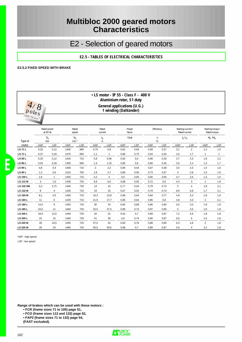
Range of brakes which can be used with these motors :• FCR (frame sizes 71 to 100) page 51,• FCO (frame sizes 112 and 132) page 52,• FAP2 (frame sizes 71 to 132) page 54,(FAST excluded).
162
E2 - Selection of geared motors
E2.5 - TABLES OF ELECTRICAL CHARACTERISTICS
Multibloc 2000 geared motorsCharacteristics
E
E2.5.2 FIXED SPEED WITH BRAKE
Rated power Rated Rated Power Efficiency Starting current / Starting torque /at 50 Hz speed current factor Rated current Rated torque
PN NN IN Cos ϕ η ID / IN MD / MN Type of kW min-1 A %
motor HSP LSP HSP LSP HSP LSP HSP LSP HSP LSP HSP LSP HSP LSP
LS 71 L 0,25 0,12 1400 685 0,75 0,8 0,81 0,63 0,58 0,37 3,1 2 1,3 1,5
LS 71 L 0,37 0,18 1370 650 1,1 1 0,86 0,75 0,54 0,34 2,5 1,7 1 1
LS 80 L 0,25 0,12 1420 710 0,8 0,96 0,92 0,6 0,56 0,33 3,7 2,3 1,9 2,2
LS 80 L 0,55 0,28 1400 690 1,3 1,25 0,85 0,6 0,66 0,46 3,5 2,4 1,4 1,7
LS 90 L 0,8 0,4 1400 710 2 2,2 0,85 0,54 0,67 0,48 3,5 2,3 1,5 1,6
LS 90 L 1,2 0,6 1410 700 2,8 2,7 0,86 0,56 0,73 0,57 4 2,8 1,5 1,9
LS 100 L 1,8 1 1400 710 4,2 4 0,9 0,65 0,66 0,56 3,7 2,6 1,3 1,5
LS 112 M 3 1,5 1430 720 6,8 6,5 0,88 0,55 0,72 0,6 4,4 3 1 1,8
LS 132 SM 5,5 2,75 1440 720 13 10 0,77 0,54 0,79 0,73 5 4 1,8 2,1
LS 132 M 8 4 1430 710 19 15 0,67 0,52 0,79 0,74 8,9 6,8 1,7 2,1
LS 160 M 8,1 4,5 1450 715 16,4 13,8 0,89 0,64 0,84 0,77 4,9 3,4 1,8 1,9
LS 160 L 11 6 1445 715 21,9 17,7 0,89 0,64 0,85 0,8 4,8 3,3 2 2,1
LS 180 L 14,5 9 1455 720 30 24 0,85 0,68 0,86 0,84 4,5 3,5 1,8 1,9
LS 180 L 16,5 11 1460 720 32,5 27,5 0,88 0,72 0,87 0,85 5 3,5 1,9 1,8
LS 200 L 18,5 12,5 1460 725 34 31 0,91 0,7 0,89 0,87 7,2 4,9 1,8 1,8
LS 200 L 22 15 1460 725 41 35 0,9 0,74 0,90 0,87 6,5 5 1,6 1,6
LS 225 M 28 19,5 1455 725 57,5 44 0,83 0,76 0,88 0,89 6,3 4,8 2 1,8
LS 225 M 34 24 1460 720 65,5 59,5 0,88 0,7 0,89 0,87 5,6 4 2,2 1,8
HSP : high speed
LSP : low speed
• LS motor - IP 55 - Class F - 400 VAluminium rotor, S1 duty
General applications (U.G.)1 winding (Dahlander)
2Pôles3000 min-1
4/8poles1500/750 min -1
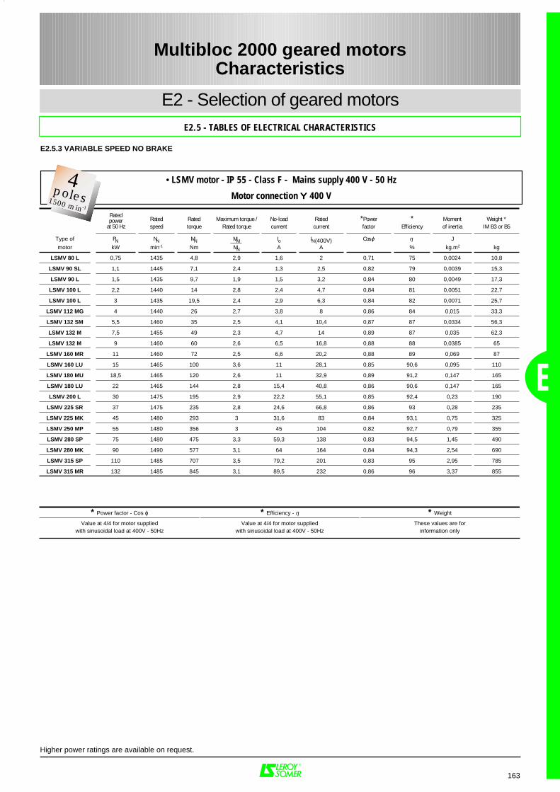
* Power factor - Cos ϕ * Efficiency - η * Weight
Value at 4/4 for motor suppliedwith sinusoidal load at 400V - 50Hz
Value at 4/4 for motor suppliedwith sinusoidal load at 400V - 50Hz
These values are forinformation only
163
E
Multibloc 2000 geared motorsCharacteristics
Rated Rated Maximum torque / No-load Rated *Power * Moment Weight *speed torque Rated torque current current factor Efficiency of inertia IM B3 or B5
Type of PN NN MN MM Io IN(400V) Cos ϕ η J
motor kW min-1 Nm MN A A % kg.m2 kg
LSMV 80 L 0,75 1435 4,8 2,9 1,6 2 0,71 75 0,0024 10,8
LSMV 90 SL 1,1 1445 7,1 2,4 1,3 2,5 0,82 79 0,0039 15,3
LSMV 90 L 1,5 1435 9,7 1,9 1,5 3,2 0,84 80 0,0049 17,3
LSMV 100 L 2,2 1440 14 2,8 2,4 4,7 0,84 81 0,0051 22,7
LSMV 100 L 3 1435 19,5 2,4 2,9 6,3 0,84 82 0,0071 25,7
LSMV 112 MG 4 1440 26 2,7 3,8 8 0,86 84 0,015 33,3
LSMV 132 SM 5,5 1460 35 2,5 4,1 10,4 0,87 87 0,0334 56,3
LSMV 132 M 7,5 1455 49 2,3 4,7 14 0,89 87 0,035 62,3
LSMV 132 M 9 1460 60 2,6 6,5 16,8 0,88 88 0,0385 65
LSMV 160 MR 11 1460 72 2,5 6,6 20,2 0,88 89 0,069 87
LSMV 160 LU 15 1465 100 3,6 11 28,1 0,85 90,6 0,095 110
LSMV 180 MU 18,5 1465 120 2,6 11 32,9 0,89 91,2 0,147 165
LSMV 180 LU 22 1465 144 2,8 15,4 40,8 0,86 90,6 0,147 165
LSMV 200 L 30 1475 195 2,9 22,2 55,1 0,85 92,4 0,23 190
LSMV 225 SR 37 1475 235 2,8 24,6 66,8 0,86 93 0,28 235
LSMV 225 MK 45 1480 293 3 31,6 83 0,84 93,1 0,75 325
LSMV 250 MP 55 1480 356 3 45 104 0,82 92,7 0,79 355
LSMV 280 SP 75 1480 475 3,3 59,3 138 0,83 94,5 1,45 490
LSMV 280 MK 90 1490 577 3,1 64 164 0,84 94,3 2,54 690
LSMV 315 SP 110 1485 707 3,5 79,2 201 0,83 95 2,95 785
LSMV 315 MR 132 1485 845 3,1 89,5 232 0,86 96 3,37 855
Ratedpower
at 50 Hz
Higher power ratings are available on request.
E2 - Selection of geared motorsE2.5 - TABLES OF ELECTRICAL CHARACTERISTICS
E2.5.3 VARIABLE SPEED NO BRAKE
• LSMV motor - IP 55 - Class F - Mains supply 400 V - 50 Hz
Motor connection ΥΥΥΥ 400 V2
Pôles3000 min-1
4poles1500 min-1
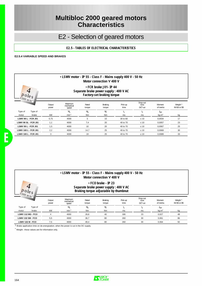
164
Multibloc 2000 geared motorsCharacteristics
E
E2 - Selection of geared motors
E2.5 - TABLES OF ELECTRICAL CHARACTERISTICS
E2.5.4 VARIABLE SPEED AND BRAKES
Output Rated Braking Pick-up Moment Weight *power torque torque time of inertia IM B3 or B5
Type of Type of MS MN MF t1 t2 JMF
motor brake kW min-1 Nm Nm ms ms kg.m2 kg
LSMV 80 L - FCR J01 0,75 4000 5 10 30 to 60 ≤ 10 0,0034 17
LSMV 90 SL - FCR J01 1,1 4000 7,4 20 40 to 70 ≤ 10 0,0057 23
LSMV 90 L - FCR J01 1,5 4000 10 20 40 to 70 ≤ 10 0,0067 25
LSMV 100 L - FCR J01 2,2 4000 14,7 25 40 to 70 ≤ 10 0,0069 30
LSMV 100 L - FCR J01 3 4000 19 25 40 to 70 ≤ 10 0,0089 33
Drop-outtime
DC1 cut
Maximummechanical
speed
Output Rated Braking Pick-up Moment Weight *power torque torque time of inertia IM B3 or B5
Type of Type of MS MN MF t1 t2 JMF
motor brake kW min-1 Nm Nm ms ms kg.m2 kg
LSMV 112 MG - FCO 4 4000 26,8 40 180 23 0,027 48
LSMV 132 SM - FCO 5,5 4000 36,7 80 260 30 0,061 86
LSMV 132 M - FCO 7,5 4000 49,4 80 260 30 0,064 92
1 Brake application time on de-energisation, when the power is cut in the DC supply.
* Weight : these values are for information only.
Maximummechanical
speed
• LSMV motor - IP 55 - Class F - Mains supply 400 V - 50 HzMotor connection ΥΥΥΥ 400 V
• FCR brake J01- IP 44Separate brake power supply : 400 V AC
Factory-set braking torque
• LSMV motor - IP 55 - Class F - Mains supply 400 V - 50 HzMotor connection ΥΥΥΥ 400 V
• FCO brake - IP 23Separate brake power supply : 400 V ACBraking torque adjustable by thumbnut
Drop-outtime
DC1 cut
2Pôles3000 min-1
4poles1500 min-1
2Pôles3000 min-1
4poles1500 min-1
F1 - Gearboxes and geared motors 166
F1.1 - Dimensions of protective cover ......................................................................... 166
F1.2 - Output shaft and details of gearbox form........................................................... 167
F1.3 - Dimensions and weight of "AP" gearboxes .......................................................168 to 175
F1.4 - Dimensions and weight of geared motors, 1 train .............................................176 to 191
F1.5 - Dimensions and weight of geared motors, 2 and 3 trains.................................. 192 to 207
F2 - Applications - Variable speed 208
F2.1 - Dimensions of LSMV variable speed drive motors
and options ........................................................................................................208 to 209
165
F
PAGES
Multibloc 2000 geared motorsDimensions
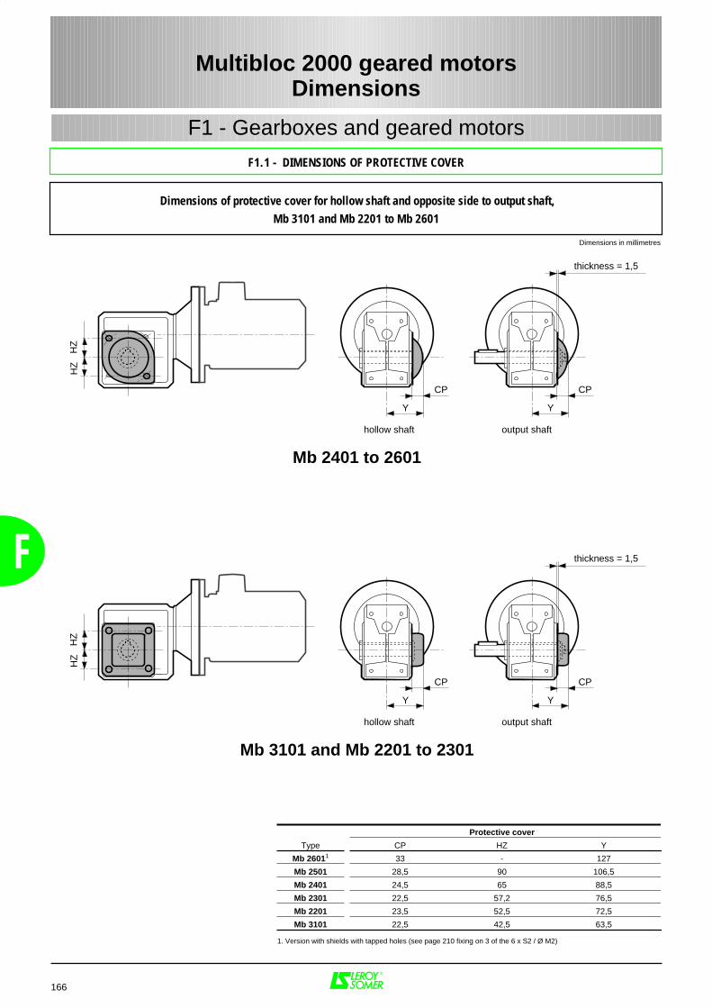
Multibloc 2000 geared motorsDimensions
Dimensions of protective cover for hollow shaft and opposite side to output shaft,Mb 3101 and Mb 2201 to Mb 2601
Dimensions in millimetres
CP
Y
CP
thickness = 1,5
Y
HZ
HZ
hollow shaft output shaft
Protective cover
Type CP HZ Y
Mb 26011 33 - 127
Mb 2501 28,5 90 106,5
Mb 2401 24,5 65 88,5
Mb 2301 22,5 57,2 76,5
Mb 2201 23,5 52,5 72,5
Mb 3101 22,5 42,5 63,5
166
F
F1 - Gearboxes and geared motors
F1.1 - DIMENSIONS OF PROTECTIVE COVER
1. Version with shields with tapped holes (see page 210 fixing on 3 of the 6 x S2 / Ø M2)
Mb 2401 to 2601
CP
Y
CP
thickness = 1,5
Y
HZ
HZ
hollow shaft output shaft
Mb 3101 and Mb 2201 to 2301
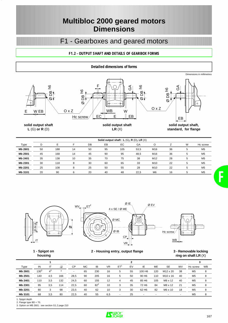
F
F1 - Gearboxes and geared motors
167
Solid output shaft : L (G), R (D), LR (X)
Type D E F DB EB EC GA O Z W Hc screw
Mb 2601 50 188 14 50 95 105 53,5 M16 36 5 M5
Mb 2501 45 168 14 45 90 95 48,5 M16 36 5 M5
Mb 2401 35 138 10 35 70 75 38 M12 28 5 M5
Mb 2301 30 118 8 30 60 65 33 M10 22 5 M5
Mb 2201 25 108 8 25 50 55 28 M10 22 5 M5
Mb 3101 20 90 6 20 40 48 22,5 M6 16 5 M5
WB
Hc screw EC EB
Ø D
Bh6
F
GA
Ø D
Bh6
O x Z
GA
EBWE
Ø D
Bh6
Ø D
Bh6
E EBWO x Z
1 2 3
Type IN IT CP MC IB VR ET1 EV IE ME SE WV Hc screw WB
Mb 2601 1303 43 3 - 65 230 16 5 55 100 H6 120 M12 x 20 38 M5 8
Mb 2501 140 4,5 166 28,5 90 205 16 5 50 90 H6 110 M10 x 16 40 M5 8
Mb 2401 110 3,5 132 24,5 60 155 12 4 45 85 H6 105 M8 x 12 40 M5 8
Mb 2301 95 3,5 114 22,5 60 822 10 3 35 72 H6 84 M8 x 12 21 M5 8
Mb 2201 80 3 98 23,5 40 62 10 3 30 62 H6 82 M6 x 10 18 M5 8
Mb 3101 68 3,5 80 22,5 40 55 6,5 - 25 - - - - M5 8
Ø MC
Ø IB
IT
Ø IN
j6
VR
CPWB
Hc screw
WV4 x SE / Ø ME
Ø IE Ø EVET1
solid output shaftL (G) or R (D)
solid output shaftLR (X)
solid output shaft,standard, for flange
1 - Spigot on housing
Dimensions in millimetres
3 - Removable lockingring on shaft LR (X)
2 - Housing entry, output flange
1. Spigot depth2. Flange type BD = 70.3. Option on MB 2601 : see section G1.2 page 210
Multibloc 2000 geared motorsDimensions
F1.2 - OUTPUT SHAFT AND DETAILS OF GEARBOX FORMS
Detailed dimensions of forms
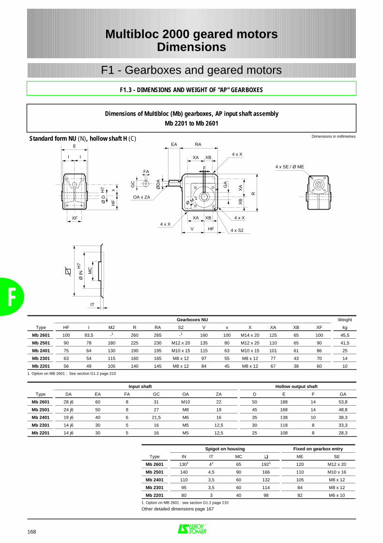
F
168
RA
XB4 x X
F
4 x X4 x X
4 x S2
R
XA
XB
GA
XA XB
V
XAI I
E
Ø D
H7 x
HF
XF
FA
ØD
A
GC
OA x ZA
EA
Ø M 2
HF
IT
Ø IN
H7
MC
4 x SE / Ø ME
Gearboxes NU Weight
Type HF I M2 R RA S2 V x X XA XB XF kg
Mb 2601 100 93,5 -1 260 265 -1 160 100 M14 x 20 125 65 100 45,5
Mb 2501 90 78 180 225 230 M12 x 20 135 80 M12 x 20 110 65 90 41,5
Mb 2401 75 64 130 190 195 M10 x 15 115 63 M10 x 15 101 61 86 25
Mb 2301 63 54 115 160 165 M8 x 12 97 55 M8 x 12 77 43 70 14
Mb 2201 56 49 105 140 145 M8 x 12 84 45 M8 x 12 67 38 60 10
1. Option on MB 2601 : See section G1.2 page 210
Input shaft Hollow output shaft
Type DA EA FA GC OA ZA D E F GA
Mb 2601 28 j6 60 8 31 M10 22 50 188 14 53,8
Mb 2501 24 j6 50 8 27 M8 19 45 168 14 48,8
Mb 2401 19 j6 40 6 21,5 M6 16 35 138 10 38,3
Mb 2301 14 j6 30 5 16 M5 12,5 30 118 8 33,3
Mb 2201 14 j6 30 5 16 M5 12,5 25 108 8 28,3
Spigot on housing Fixed on gearbox entry
Type IN IT MC ME SE
Mb 2601 1301 41 65 1921 120 M12 x 20
Mb 2501 140 4,5 90 166 110 M10 x 16
Mb 2401 110 3,5 60 132 105 M8 x 12
Mb 2301 95 3,5 60 114 84 M8 x 12
Mb 2201 80 3 40 98 82 M6 x 10
1. Option on MB 2601 : see section G1.2 page 210
Other detailed dimensions page 167
F1 - Gearboxes and geared motors
Dimensions in millimetresStandard form NU (N), hollow shaft H (C)
Multibloc 2000 geared motorsDimensions
F1.3 - DIMENSIONS AND WEIGHT OF "AP" GEARBOXES
Dimensions of Multibloc (Mb) gearboxes, AP input shaft assemblyMb 2201 to Mb 2601
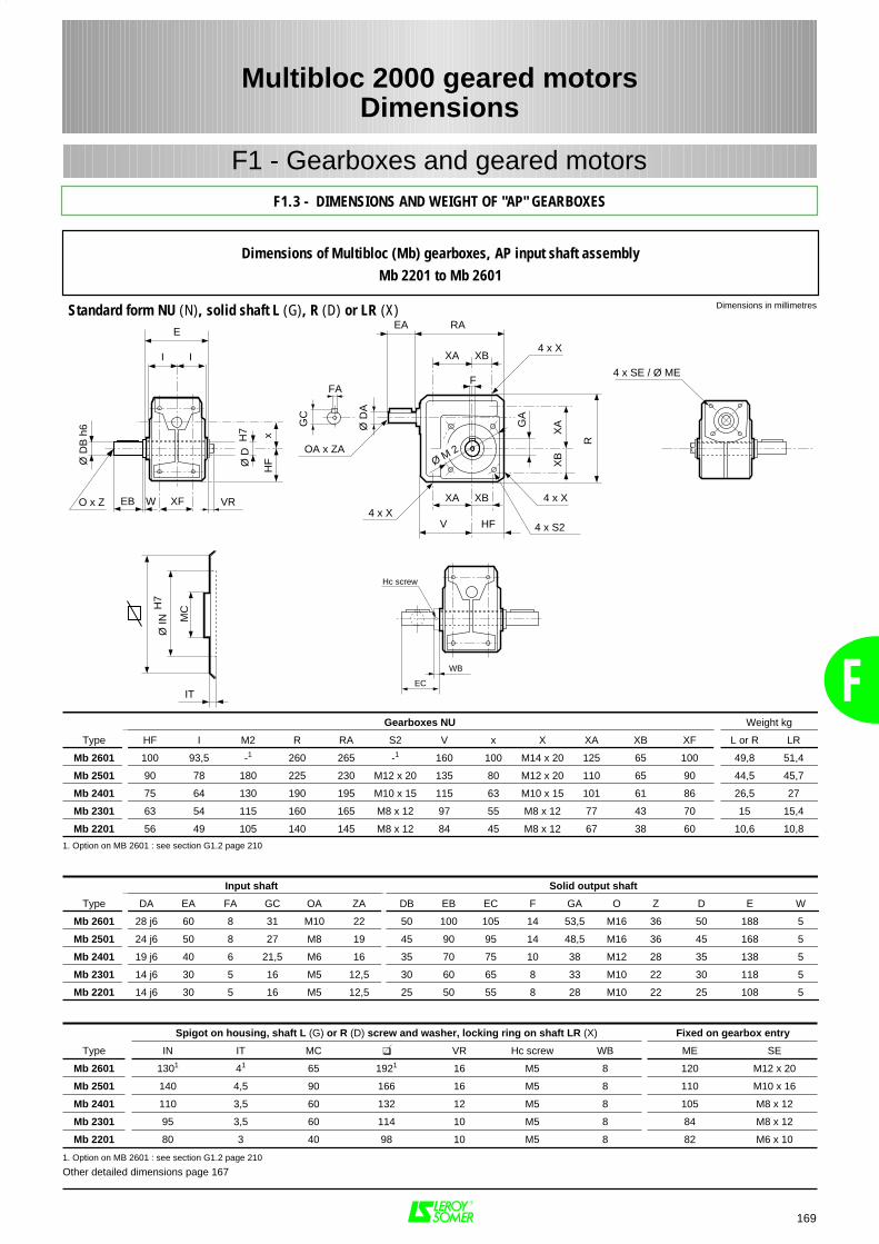
F
169
F1 - Gearboxes and geared motors
Spigot on housing, shaft L (G) or R (D) screw and washer, locking ring on shaft LR (X) Fixed on gearbox entry
Type IN IT MC VR Hc screw WB ME SE
Mb 2601 1301 41 65 1921 16 M5 8 120 M12 x 20
Mb 2501 140 4,5 90 166 16 M5 8 110 M10 x 16
Mb 2401 110 3,5 60 132 12 M5 8 105 M8 x 12
Mb 2301 95 3,5 60 114 10 M5 8 84 M8 x 12
Mb 2201 80 3 40 98 10 M5 8 82 M6 x 10
1. Option on MB 2601 : see section G1.2 page 210
Other detailed dimensions page 167
RA
XB4 x X
F
4 x X4 x X
4 x S2
R
XA
XB
GA
XA XB
V
XAI I
E
Ø D
H7 x
HF
XF
FA
Ø D
A
GC
OA x ZA
EA
Ø M 2
HF
EB W
Ø D
B h
6
O x Z VR
IT
Ø IN
H7
MC
WB
Hc screw
4 x SE / Ø ME
EC
Gearboxes NU Weight kg
Type HF I M2 R RA S2 V x X XA XB XF L or R LR
Mb 2601 100 93,5 -1 260 265 -1 160 100 M14 x 20 125 65 100 49,8 51,4
Mb 2501 90 78 180 225 230 M12 x 20 135 80 M12 x 20 110 65 90 44,5 45,7
Mb 2401 75 64 130 190 195 M10 x 15 115 63 M10 x 15 101 61 86 26,5 27
Mb 2301 63 54 115 160 165 M8 x 12 97 55 M8 x 12 77 43 70 15 15,4
Mb 2201 56 49 105 140 145 M8 x 12 84 45 M8 x 12 67 38 60 10,6 10,8
1. Option on MB 2601 : see section G1.2 page 210
Input shaft Solid output shaft
Type DA EA FA GC OA ZA DB EB EC F GA O Z D E W
Mb 2601 28 j6 60 8 31 M10 22 50 100 105 14 53,5 M16 36 50 188 5
Mb 2501 24 j6 50 8 27 M8 19 45 90 95 14 48,5 M16 36 45 168 5
Mb 2401 19 j6 40 6 21,5 M6 16 35 70 75 10 38 M12 28 35 138 5
Mb 2301 14 j6 30 5 16 M5 12,5 30 60 65 8 33 M10 22 30 118 5
Mb 2201 14 j6 30 5 16 M5 12,5 25 50 55 8 28 M10 22 25 108 5
Multibloc 2000 geared motorsDimensions
F1.3 - DIMENSIONS AND WEIGHT OF "AP" GEARBOXES
Dimensions in millimetresStandard form NU (N), solid shaft L (G), R (D) or LR (X)
Dimensions of Multibloc (Mb) gearboxes, AP input shaft assemblyMb 2201 to Mb 2601
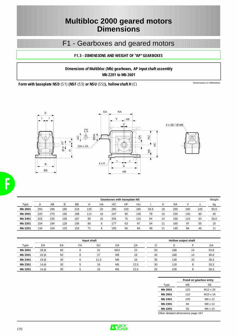
F
170
F1 - Gearboxes and geared motors
RA
V
F
4 x K
HC
GA
==
A
AB
HU
HA
I I
E
B
BB
Ø D
H7 x
H
FA
ØD
A
GC
OA x ZA
EA
HF
4 x SE / Ø ME
Input shaft Hollow output shaft
Type DA EA FA GC OA ZA D E F GA
Mb 2601 28 j6 60 8 31 M10 22 50 188 14 53,8
Mb 2501 24 j6 50 8 27 M8 19 45 168 14 48,8
Mb 2401 19 j6 40 6 21,5 M6 16 35 138 10 38,3
Mb 2301 14 j6 30 5 16 M5 12,5 30 118 8 33,3
Mb 2201 14 j6 30 5 16 M5 12,5 25 108 8 28,3
Gearboxes with baseplate NS Weight
Type A AB B BB H HA HC HF HU I K RA V x kg
Mb 2601 250 296 180 216 125 20 285 100 160 93,5 18 265 160 100 50,5
Mb 2501 220 270 156 188 112 16 247 90 135 78 16 230 135 80 45
Mb 2401 202 235 156 187 90 15 205 75 115 64 14 195 115 63 26,5
Mb 2301 154 184 128 156 80 6 177 63 97 54 11 165 97 55 15
Mb 2201 134 164 125 153 71 6 155 56 84 49 11 145 84 45 11
Fixed on gearbox entry
Type ME SE
Mb 2601 120 M12 x 20
Mb 2501 110 M10 x 16
Mb 2401 105 M8 x 12
Mb 2301 84 M8 x 12
Mb 2201 82 M6 x 10
Other detailed dimensions page 167
Multibloc 2000 geared motorsDimensions
F1.3 - DIMENSIONS AND WEIGHT OF "AP" GEARBOXES
Dimensions in millimetresForm with baseplate NSD (S1) (NSF (S3) or NSU (S5)), hollow shaft H (C)
Dimensions of Multibloc (Mb) gearboxes, AP input shaft assemblyMb 2201 to Mb 2601
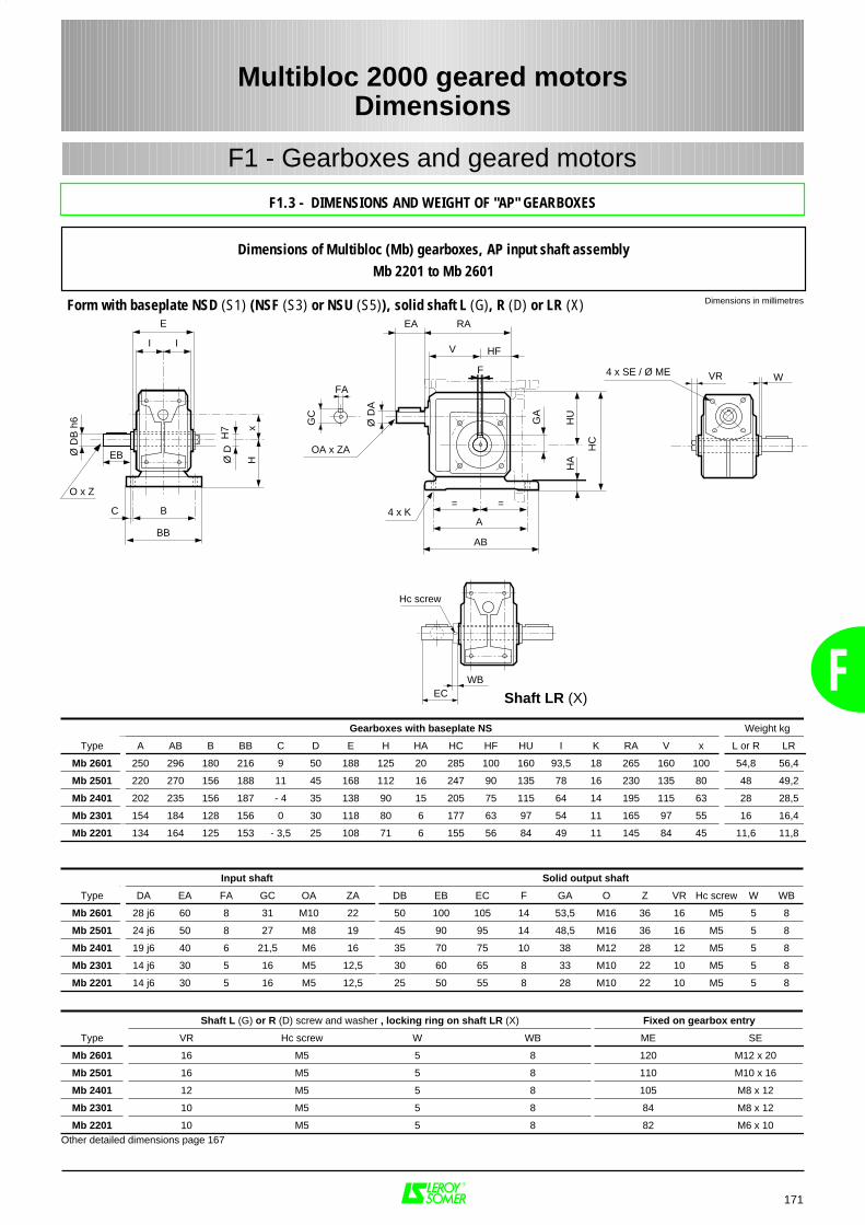
F
171
Multibloc 2000 geared motorsDimensions
F1 - Gearboxes and geared motors
F1.3 - DIMENSIONS AND WEIGHT OF "AP" GEARBOXES
RA
V
F
4 x K
HC
GA
==
A
AB
HU
HA
I I
E
B
BB
Ø D
H7 x
H
FA
Ø D
A
GC
OA x ZA
EA
HF
EB
C
Ø D
B h
6
O x Z
4 x SE / Ø ME VR W
WB
Hc screw
EC
Dimensions in millimetresForm with baseplate NSD (S1) (NSF (S3) or NSU (S5)), solid shaft L (G), R (D) or LR (X)
Dimensions of Multibloc (Mb) gearboxes, AP input shaft assemblyMb 2201 to Mb 2601
Shaft L (G) or R (D) screw and washer , locking ring on shaft LR (X) Fixed on gearbox entry
Type VR Hc screw W WB ME SE
Mb 2601 16 M5 5 8 120 M12 x 20
Mb 2501 16 M5 5 8 110 M10 x 16
Mb 2401 12 M5 5 8 105 M8 x 12
Mb 2301 10 M5 5 8 84 M8 x 12
Mb 2201 10 M5 5 8 82 M6 x 10Other detailed dimensions page 167
Gearboxes with baseplate NS Weight kg
Type A AB B BB C D E H HA HC HF HU I K RA V x L or R LR
Mb 2601 250 296 180 216 9 50 188 125 20 285 100 160 93,5 18 265 160 100 54,8 56,4
Mb 2501 220 270 156 188 11 45 168 112 16 247 90 135 78 16 230 135 80 48 49,2
Mb 2401 202 235 156 187 - 4 35 138 90 15 205 75 115 64 14 195 115 63 28 28,5
Mb 2301 154 184 128 156 0 30 118 80 6 177 63 97 54 11 165 97 55 16 16,4
Mb 2201 134 164 125 153 - 3,5 25 108 71 6 155 56 84 49 11 145 84 45 11,6 11,8
Input shaft Solid output shaft
Type DA EA FA GC OA ZA DB EB EC F GA O Z VR Hc screw W WB
Mb 2601 28 j6 60 8 31 M10 22 50 100 105 14 53,5 M16 36 16 M5 5 8
Mb 2501 24 j6 50 8 27 M8 19 45 90 95 14 48,5 M16 36 16 M5 5 8
Mb 2401 19 j6 40 6 21,5 M6 16 35 70 75 10 38 M12 28 12 M5 5 8
Mb 2301 14 j6 30 5 16 M5 12,5 30 60 65 8 33 M10 22 10 M5 5 8
Mb 2201 14 j6 30 5 16 M5 12,5 25 50 55 8 28 M10 22 10 M5 5 8
Shaft LR (X)
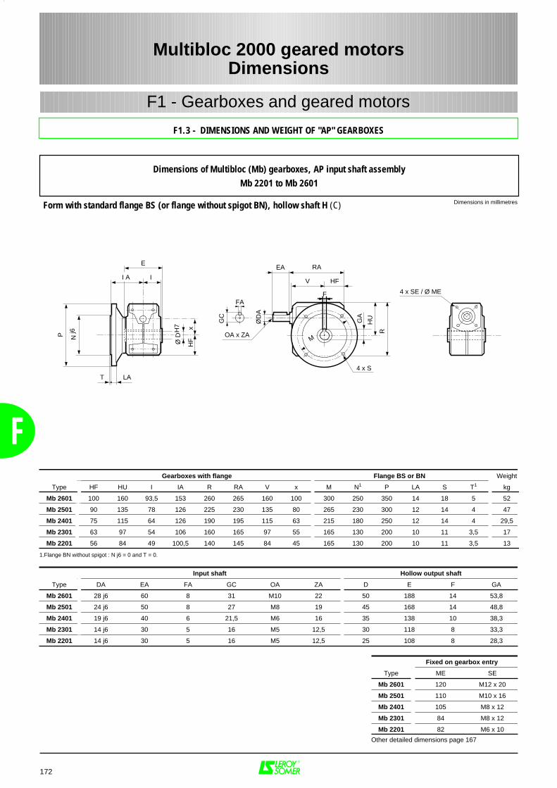
F
172
RA
4 x S
R
GA
F
V
HU
I A I
E
Ø D
H7 x
HF
T LA
P Nj6
M
FA
ØD
A
GC
OA x ZA
EA
HF
4 x SE / Ø ME
Multibloc 2000 geared motorsDimensions
F1 - Gearboxes and geared motors
F1.3 - DIMENSIONS AND WEIGHT OF "AP" GEARBOXES
Dimensions in millimetresForm with standard flange BS (or flange without spigot BN), hollow shaft H (C)
Dimensions of Multibloc (Mb) gearboxes, AP input shaft assemblyMb 2201 to Mb 2601
Input shaft Hollow output shaft
Type DA EA FA GC OA ZA D E F GA
Mb 2601 28 j6 60 8 31 M10 22 50 188 14 53,8
Mb 2501 24 j6 50 8 27 M8 19 45 168 14 48,8
Mb 2401 19 j6 40 6 21,5 M6 16 35 138 10 38,3
Mb 2301 14 j6 30 5 16 M5 12,5 30 118 8 33,3
Mb 2201 14 j6 30 5 16 M5 12,5 25 108 8 28,3
Gearboxes with flange Flange BS or BN Weight
Type HF HU I IA R RA V x M N1 P LA S T1 kg
Mb 2601 100 160 93,5 153 260 265 160 100 300 250 350 14 18 5 52
Mb 2501 90 135 78 126 225 230 135 80 265 230 300 12 14 4 47
Mb 2401 75 115 64 126 190 195 115 63 215 180 250 12 14 4 29,5
Mb 2301 63 97 54 106 160 165 97 55 165 130 200 10 11 3,5 17
Mb 2201 56 84 49 100,5 140 145 84 45 165 130 200 10 11 3,5 13
1.Flange BN without spigot : N j6 = 0 and T = 0.
Fixed on gearbox entry
Type ME SE
Mb 2601 120 M12 x 20
Mb 2501 110 M10 x 16
Mb 2401 105 M8 x 12
Mb 2301 84 M8 x 12
Mb 2201 82 M6 x 10
Other detailed dimensions page 167
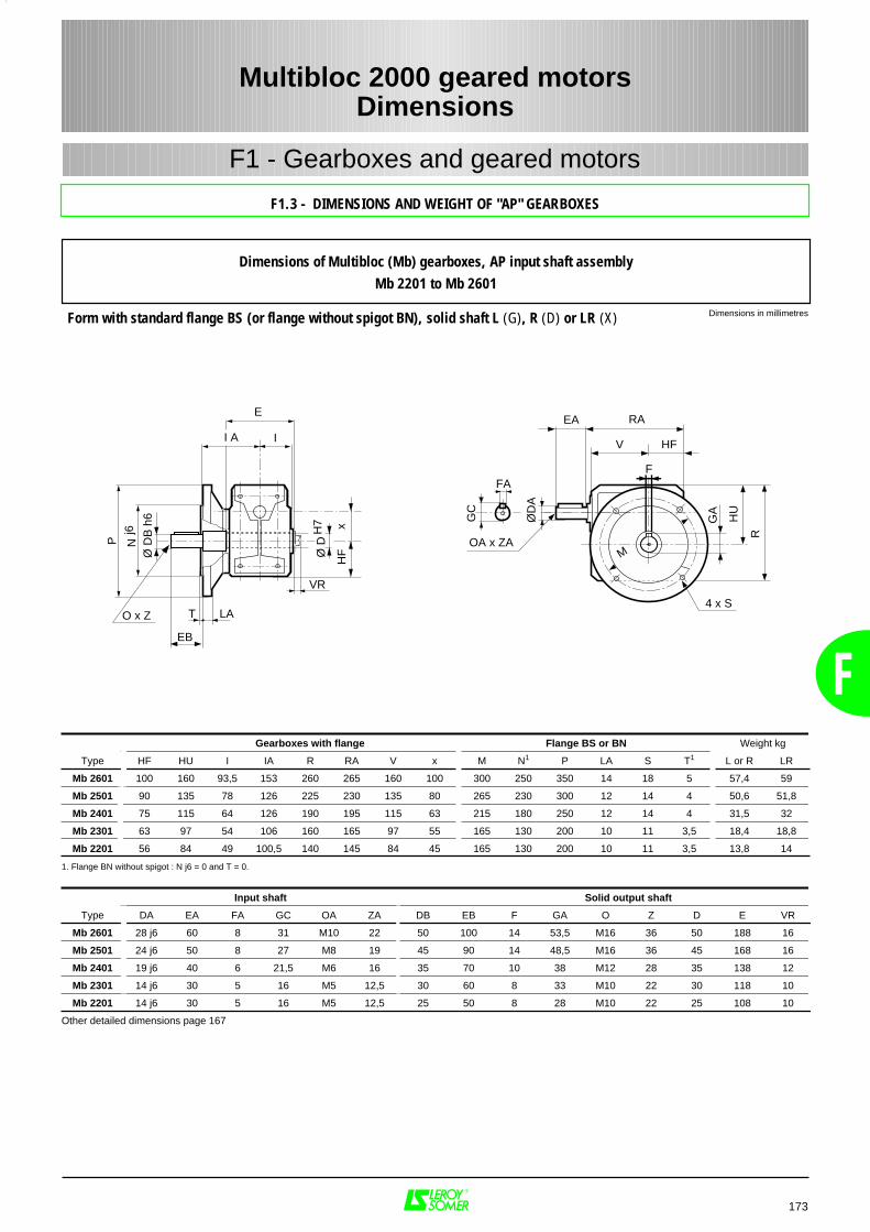
F
173
RA
4 x S
R
GA
F
V
HU
M
FA
ØD
A
GC
OA x ZA
EA
HF
T LA
EB
P Nj6
Ø D
B h
6
O x Z
I A I
E
VR
Ø D
H7 x
HF
Multibloc 2000 geared motorsDimensions
F1 - Gearboxes and geared motors
F1.3 - DIMENSIONS AND WEIGHT OF "AP" GEARBOXES
Dimensions in millimetresForm with standard flange BS (or flange without spigot BN), solid shaft L (G), R (D) or LR (X)
Dimensions of Multibloc (Mb) gearboxes, AP input shaft assemblyMb 2201 to Mb 2601
Input shaft Solid output shaft
Type DA EA FA GC OA ZA DB EB F GA O Z D E VR
Mb 2601 28 j6 60 8 31 M10 22 50 100 14 53,5 M16 36 50 188 16
Mb 2501 24 j6 50 8 27 M8 19 45 90 14 48,5 M16 36 45 168 16
Mb 2401 19 j6 40 6 21,5 M6 16 35 70 10 38 M12 28 35 138 12
Mb 2301 14 j6 30 5 16 M5 12,5 30 60 8 33 M10 22 30 118 10
Mb 2201 14 j6 30 5 16 M5 12,5 25 50 8 28 M10 22 25 108 10
Other detailed dimensions page 167
Gearboxes with flange Flange BS or BN Weight kg
Type HF HU I IA R RA V x M N1 P LA S T1 L or R LR
Mb 2601 100 160 93,5 153 260 265 160 100 300 250 350 14 18 5 57,4 59
Mb 2501 90 135 78 126 225 230 135 80 265 230 300 12 14 4 50,6 51,8
Mb 2401 75 115 64 126 190 195 115 63 215 180 250 12 14 4 31,5 32
Mb 2301 63 97 54 106 160 165 97 55 165 130 200 10 11 3,5 18,4 18,8
Mb 2201 56 84 49 100,5 140 145 84 45 165 130 200 10 11 3,5 13,8 14
1. Flange BN without spigot : N j6 = 0 and T = 0.
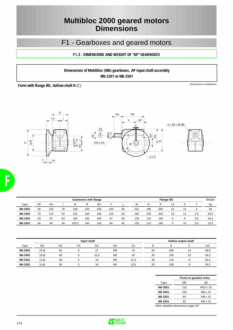
F
174
RA
4 x SR
GA
F
V
HU
I A I
E
Ø D
H7 x
HF
T LA
P Nj6
M
FA
ØD
A
GC
OA x ZA
EA
HF
4 x SE / Ø ME
Multibloc 2000 geared motorsDimensions
F1 - Gearboxes and geared motors
F1.3 - DIMENSIONS AND WEIGHT OF "AP" GEARBOXES
Dimensions in millimetresForm with flange BD, hollow shaft H (C)
Dimensions of Multibloc (Mb) gearboxes, AP input shaft assemblyMb 2201 to Mb 2501
Input shaft Hollow output shaft
Type DA EA FA GC OA ZA D E F GA
Mb 2501 24 j6 50 8 27 M8 19 45 168 14 48,8
Mb 2401 19 j6 40 6 21,5 M6 16 35 138 10 38,3
Mb 2301 14 j6 30 5 16 M5 12,5 30 118 8 33,3
Mb 2201 14 j6 30 5 16 M5 12,5 25 108 8 28,3
Gearboxes with flange Flange BD Weight
Type HF HU I IA R RA V x M N P LA S T kg
Mb 2501 90 135 78 138 225 230 135 80 215 180 250 12 14 4 46
Mb 2401 75 115 64 126 190 195 115 63 165 130 200 10 11 3,5 28,5
Mb 2301 63 97 54 106 160 165 97 55 130 110 160 9 9 3,5 16,5
Mb 2201 56 84 49 100,5 140 145 84 45 130 110 160 9 10 3,5 12,5
Fixed on gearbox entry
Type ME SE
Mb 2501 110 M10 x 16
Mb 2401 105 M8 x 12
Mb 2301 84 M8 x 12
Mb 2201 82 M6 x 10
Other detailed dimensions page 167

F
175
RA
4 x S
R
GA
F
V
HU
M
FA
ØD
A
GC
OA x ZA
EA
HF
T LA
EB
P Nj6
Ø D
B h
6
O x Z
I A I
E
VR
Ø D
H7 x
HF
Multibloc 2000 geared motorsDimensions
F1 - Gearboxes and geared motors
F1.3 - DIMENSIONS AND WEIGHT OF "AP" GEARBOXES
Dimensions in millimetresForm with flange BD, solid shaft L (G), R (D) or LR (X)
Dimensions of Multibloc (Mb) gearboxes, AP input shaft assemblyMb 2201 to Mb 2501
Input shaft Solid output shaft
Type DA EA FA GC OA ZA DB EB F GA O Z D E VR
Mb 2501 24 j6 50 8 27 M8 19 45 90 14 48,5 M16 36 45 168 16
Mb 2401 19 j6 40 6 21,5 M6 16 35 70 10 38 M12 28 35 138 12
Mb 2301 14 j6 30 5 16 M5 12,5 30 60 8 33 M10 22 30 118 10
Mb 2201 14 j6 30 5 16 M5 12,5 25 50 8 28 M10 22 25 108 10
Other detailed dimensions page 167
Gearboxes with flange Flange BD Weight kg
Type HF HU I IA R RA V x M N P LA S T L or R LR
Mb 25011 90 135 78 138 225 230 135 80 215 180 250 12 14 4 51,4 53
Mb 2401 75 115 64 126 190 195 115 63 165 130 200 10 11 3,5 30,5 31
Mb 2301 63 97 54 106 160 165 97 55 130 110 160 9 9 3,5 17,9 18,3
Mb 2201 56 84 49 100,5 140 145 84 45 130 110 160 9 10 3,5 13,3 13,5
1. Caution, the shoulder of the shaft is set back 12 mm from the flange.
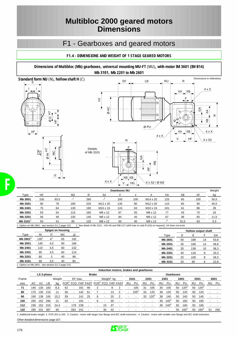
F
176
F1 - Gearboxes and geared motors
Multibloc 2000 geared motorsDimensions
Spigot on housing
Type IN IT MC
Mb 26011 1301 41 65 192
Mb 2501 140 4,5 90 166
Mb 2401 110 3,5 60 132
Mb 2301 95 3,5 60 114
Mb 2201 80 3 40 98
Mb 3101 68 3,5 40 801. Option on Mb 2601 : see section G1.2 page 210.
R
XB4 x X
F
4 x X4 x X
4 x S2
R
XA
XB
GA
XA XB
V
XAI I
E
Ø D
H7 x
HF
XF
LBEF
HJ
Ø A
C
Ø PU
RU
Ø M 2
HF
IT
Ø IN
H7
MC
Gearboxes NU Weight
Type HF I M2 R S2 V x X XA XB XF kg
Mb 2601 100 93,5 -1 260 -1 160 100 M14 x 20 125 65 100 50,5
Mb 2501 90 78 180 225 M12 x 20 135 80 M12 x 20 110 65 90 45,5
Mb 2401 75 64 130 190 M10 x 15 115 63 M10 x 15 101 61 86 28
Mb 2301 63 54 115 160 M8 x 12 97 55 M8 x 12 77 43 70 16
Mb 2201 56 49 105 140 M8 x 12 84 45 M8 x 12 67 38 60 11,5
Mb 31012 50 41 85 120 M8 x 12 50 40 M8 x 12 -2 31,5 63 5,31. Option on Mb 2601 : see section G1.2 page 210. 2. See detail of Mb 3101 : HG=45 and RB=127 (drill hole on side F (S3) on request), XA does not exist.
Induction motors, brakes and gearboxes
LS 3-phase Brake Gearboxes
Frame Weight EF max. Weight1 kg 3101 2201 2301 2401 2501 2601
size AC HJ LB kg FCR2 FCO FAP FAST FCR2 FCO FAP FAST RU PU RU PU RU PU RU PU RU PU RU PU
71 140 130 183 8,3 62 - 181 46 3 - 8 2 - 105 31 105 35 105 50 1203 50 1203 - -
80 170 130 215 11 50 - 142 51 7 - 13 2 - 1054 33 120 36 120 50 120 50 120 - -
90 190 138 245 15,2 59 - 141 25 9 - 20 2 - - 33 1204 38 140 50 140 50 140 - -
100 200 152 290 21 62 - 191 - 9 - 30 - - - - - 35 1404 50 160 50 160 - -
112 235 152 315 24,4 - 179 228 - - 15 37 - - - - - 35 1404 50 160 50 160 - -
132 280 201 387 60 - 283 241 - - 30 42 - - - - - - - 50 1604 50 1604 51 250
1. Additional brake weight. 2. FCR J01 to J03. 3. Caution : motor with larger size flange and IEC shaft extension. 4. Caution : motor with smaller size flange and IEC shaft extension.
Hollow output shaft
Type D E F GA
Mb 2601 50 188 14 53,8
Mb 2501 45 168 14 48,8
Mb 2401 35 138 10 38,3
Mb 2301 30 118 8 33,3
Mb 2201 25 108 8 28,3
Mb 3101 20 90 6 22,8
Other detailed dimensions page 167.
R
F
4 x X 4 x S2 / Ø M2
Detailsof Mb 3101
RB
GA
HF
XBXB
V HG
Dimensions in millimetresStandard form NU (N), hollow shaft H (C)
F1.4 - DIMENSIONS AND WEIGHT OF 1 STAGE GEARED MOTORS
Dimensions of Multibloc (Mb) gearboxes, universal mounting MU-FT (MU), with motor IM 3601 (IM B14)Mb 3101, Mb 2201 to Mb 2601
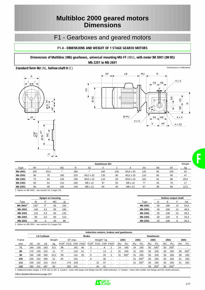
177
F1 - Gearboxes and geared motors
Dimensions in millimetresStandard form NU (N), hollow shaft H (C)
Multibloc 2000 geared motorsDimensions
F1.4 - DIMENSIONS AND WEIGHT OF 1 STAGE GEARED MOTORS
Dimensions of Multibloc (Mb) gearboxes, universal mounting MU-FF (MU), with motor IM 3001 (IM B5)Mb 2201 to Mb 2601
R
XB4 x X
F
4 x X4 x X
4 x S2
R
XA
XB
GA
XA XB
V
XAI I
E
Ø D
H7 x
HF
XF
LBEF
HJ
Ø A
C
Ø PU
RU
Ø M 2
HF
IT
Ø IN
H7
MC
Induction motors, brakes and gearboxes
LS 3-phase Brake Gearboxes
Frame Weight EF max. Weight1 kg 2201 2301 2401 2501 2601
size AC HJ LB kg FCR2 FCO FAP FAST FCR2 FCO FAP FAST RU PU RU PU RU PU RU PU RU PU
71 140 130 183 8,3 88 - 181 46 3 - 8 2 24 160 24 160 50 2003 50 2003 - -
80 170 130 215 11 77 - 142 51 7 - 13 2 31 200 31 200 50 200 50 200 59 2003
90 190 138 265 15,2 59 - 141 25 9 - 20 2 31 2004 31 200 50 200 50 200 59 200
100 200 152 290 21 82 - 191 - 9 - 30 - - - 31 2004 50 250 50 250 51 250
112 235 152 315 24,4 - 179 228 - - 15 37 - - - 31 2004 50 250 50 250 51 250
132 280 201 387 60 - 283 241 - - 30 42 - - - - - 50 2504 50 2504 - -
Gearboxes NU Weight
Type HF I M2 R S2 V x X XA XB XF kg
Mb 2601 100 93,5 -1 260 -1 160 100 M14 x 20 125 65 100 52
Mb 2501 90 78 180 225 M12 x 20 135 80 M12 x 20 110 65 90 47
Mb 2401 75 64 130 190 M10 x 15 115 63 M10 x 15 101 61 86 29,5
Mb 2301 63 54 115 160 M8 x 12 97 55 M8 x 12 77 43 70 17
Mb 2201 56 49 105 140 M8 x 12 84 45 M8 x 12 67 38 60 12,51. Option on Mb 2601 : see section G1.2 page 210.
Spigot on housing
Type IN IT MC
Mb 26011 1301 41 65 192
Mb 2501 140 4,5 90 166
Mb 2401 110 3,5 60 132
Mb 2301 95 3,5 60 114
Mb 2201 80 3 40 981. Option on Mb 2601 : see section G1.2 page 210.
1. Additional brake weight. 2. FCR J01 to J03. 3. Caution : motor with larger size flange and IEC shaft extension. 4. Caution : motor with smaller size flange and IEC shaft extension.
Hollow output shaft
Type D E F GA
Mb 2601 50 188 14 53,8
Mb 2501 45 168 14 48,8
Mb 2401 35 138 10 38,3
Mb 2301 30 118 8 33,3
Mb 2201 25 108 8 28,3
Other detailed dimensions page 167.
F
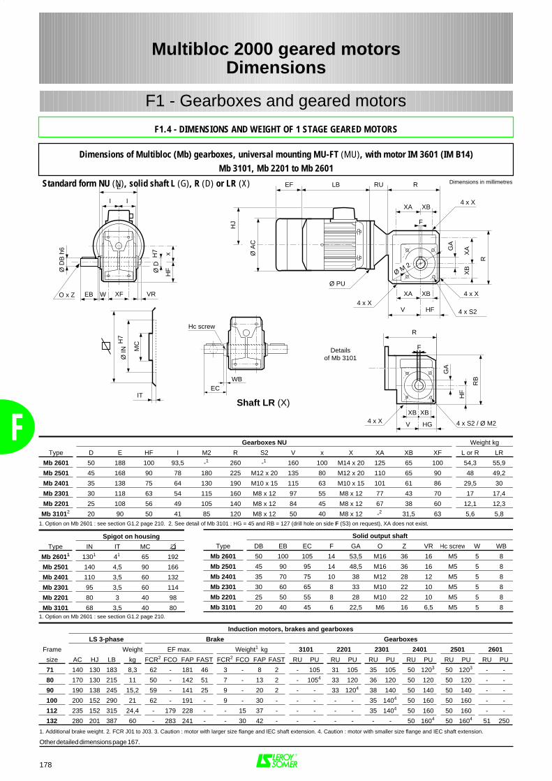
F
178
F1 - Gearboxes and geared motors
Dimensions in millimetres
Multibloc 2000 geared motorsDimensions
F1.4 - DIMENSIONS AND WEIGHT OF 1 STAGE GEARED MOTORS
Dimensions of Multibloc (Mb) gearboxes, universal mounting MU-FT (MU), with motor IM 3601 (IM B14)Mb 3101, Mb 2201 to Mb 2601
R
XB4 x X
F
4 x X4 x X
4 x S2
R
XA
XB
GA
XA XB
V
XAI I
E
Ø D
H7 x
HF
XF
LBEF
HJ
Ø A
C
Ø PU
RU
Ø M 2
HF
EB W
Ø D
B h
6
O x Z VR
IT
Ø IN
H7
MC
WB
Hc screw
EC
Gearboxes NU Weight kg
Type D E HF I M2 R S2 V x X XA XB XF L or R LR
Mb 2601 50 188 100 93,5 -1 260 -1 160 100 M14 x 20 125 65 100 54,3 55,9
Mb 2501 45 168 90 78 180 225 M12 x 20 135 80 M12 x 20 110 65 90 48 49,2
Mb 2401 35 138 75 64 130 190 M10 x 15 115 63 M10 x 15 101 61 86 29,5 30
Mb 2301 30 118 63 54 115 160 M8 x 12 97 55 M8 x 12 77 43 70 17 17,4
Mb 2201 25 108 56 49 105 140 M8 x 12 84 45 M8 x 12 67 38 60 12,1 12,3
Mb 31012 20 90 50 41 85 120 M8 x 12 50 40 M8 x 12 -2 31,5 63 5,6 5,81. Option on Mb 2601 : see section G1.2 page 210. 2. See detail of Mb 3101 : HG = 45 and RB = 127 (drill hole on side F (S3) on request), XA does not exist.
Spigot on housing
Type IN IT MC
Mb 26011 1301 41 65 192
Mb 2501 140 4,5 90 166
Mb 2401 110 3,5 60 132
Mb 2301 95 3,5 60 114
Mb 2201 80 3 40 98
Mb 3101 68 3,5 40 801. Option on Mb 2601 : see section G1.2 page 210.
Solid output shaft
Type DB EB EC F GA O Z VR Hc screw W WB
Mb 2601 50 100 105 14 53,5 M16 36 16 M5 5 8
Mb 2501 45 90 95 14 48,5 M16 36 16 M5 5 8
Mb 2401 35 70 75 10 38 M12 28 12 M5 5 8
Mb 2301 30 60 65 8 33 M10 22 10 M5 5 8
Mb 2201 25 50 55 8 28 M10 22 10 M5 5 8
Mb 3101 20 40 45 6 22,5 M6 16 6,5 M5 5 8
Induction motors, brakes and gearboxes
LS 3-phase Brake Gearboxes
Frame Weight EF max. Weight1 kg 3101 2201 2301 2401 2501 2601
size AC HJ LB kg FCR2 FCO FAP FAST FCR2 FCO FAP FAST RU PU RU PU RU PU RU PU RU PU RU PU
71 140 130 183 8,3 62 - 181 46 3 - 8 2 - 105 31 105 35 105 50 1203 50 1203 - -
80 170 130 215 11 50 - 142 51 7 - 13 2 - 1054 33 120 36 120 50 120 50 120 - -
90 190 138 245 15,2 59 - 141 25 9 - 20 2 - - 33 1204 38 140 50 140 50 140 - -
100 200 152 290 21 62 - 191 - 9 - 30 - - - - - 35 1404 50 160 50 160 - -
112 235 152 315 24,4 - 179 228 - - 15 37 - - - - - 35 1404 50 160 50 160 - -
132 280 201 387 60 - 283 241 - - 30 42 - - - - - - - 50 1604 50 1604 51 250
1. Additional brake weight. 2. FCR J01 to J03. 3. Caution : motor with larger size flange and IEC shaft extension. 4. Caution : motor with smaller size flange and IEC shaft extension.
Other detailed dimensions page 167.
R
F
4 x X 4 x S2 / Ø M2
Detailsof Mb 3101
RB
GA
HF
XBXB
V HG
Shaft LR (X)
Standard form NU (N), solid shaft L (G), R (D) or LR (X)
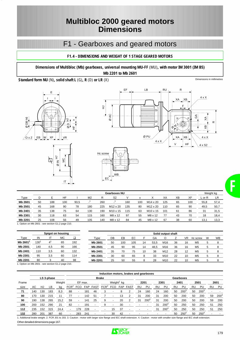
179
F1 - Gearboxes and geared motors
Dimensions in millimetresStandard form NU (N), solid shaft L (G), R (D) or LR (X)
Multibloc 2000 geared motorsDimensions
F
F1.4 - DIMENSIONS AND WEIGHT OF 1 STAGE GEARED MOTORS
Dimensions of Multibloc (Mb) gearboxes, universal mounting MU-FF (MU), with motor IM 3001 (IM B5)Mb 2201 to Mb 2601
R
XB4 x X
F
4 x X4 x X
4 x S2
R
XA
XB
GA
XA XB
V
XAI I
E
Ø D
H7 x
HF
XF
LBEF
HJ
Ø A
C
Ø PU
RU
Ø M 2
HF
EB W
Ø D
B h
6
O x Z VR
IT
Ø IN
H7
MC
WB
Hc screw
EC
Gearboxes NU Weight kg
Type D E HF I M2 R S2 V x X XA XB XF L or R LR
Mb 2601 50 188 100 93,5 -1 260 -1 160 100 M14 x 20 125 65 100 55,8 57,4
Mb 2501 45 168 90 78 180 225 M12 x 20 135 80 M12 x 20 110 65 90 49,5 50,7
Mb 2401 35 138 75 64 130 190 M10 x 15 115 63 M10 x 15 101 61 86 31 31,5
Mb 2301 30 118 63 54 115 160 M8 x 12 97 55 M8 x 12 77 43 70 18 18,4
Mb 2201 25 108 56 49 105 140 M8 x 12 84 45 M8 x 12 67 38 60 13,1 13,31. Option on Mb 2601 : see section G1.2 page 210.
Spigot on housing
Type IN IT MC
Mb 26011 1301 41 65 192
Mb 2501 140 4,5 90 166
Mb 2401 110 3,5 60 132
Mb 2301 95 3,5 60 114
Mb 2201 80 3 40 981. Option on Mb 2601 : see section G1.2 page 210.
Solid output shaft
Type DB EB EC F GA O Z VR Hc screw W WB
Mb 2601 50 100 105 14 53,5 M16 36 16 M5 5 8
Mb 2501 45 90 95 14 48,5 M16 36 16 M5 5 8
Mb 2401 35 70 75 10 38 M12 28 12 M5 5 8
Mb 2301 30 60 65 8 33 M10 22 10 M5 5 8
Mb 2201 25 50 55 8 28 M10 22 10 M5 5 8
Induction motors, brakes and gearboxes
LS 3-phase Brake Gearboxes
Frame Weight EF max. Weight1 kg 2201 2301 2401 2501 2601
size AC HJ LB kg FCR2 FCO FAP FAST FCR2 FCO FAP FAST RU PU RU PU RU PU RU PU RU PU
71 140 130 183 8,3 88 - 181 46 3 - 8 2 24 160 24 160 50 2003 50 2003 - -
80 170 130 215 11 77 - 142 51 7 - 13 2 31 200 31 200 50 200 50 200 59 2003
90 190 138 265 15,2 59 - 141 25 9 - 20 2 31 2004 31 200 50 200 50 200 59 200
100 200 152 290 21 82 - 191 - 9 - 30 - - - 31 2004 50 250 50 250 51 250
112 235 152 315 24,4 - 179 228 - - 15 37 - - - 31 2004 50 250 50 250 51 250
132 280 201 387 60 - 283 241 - - 30 42 - - - - - 50 2504 50 2504 - -1. Additional brake weight. 2. FCR J01 to J03. 3. Caution : motor with larger size flange and IEC shaft extension. 4. Caution : motor with smaller size flange and IEC shaft extension.
Other detailed dimensions page 167.
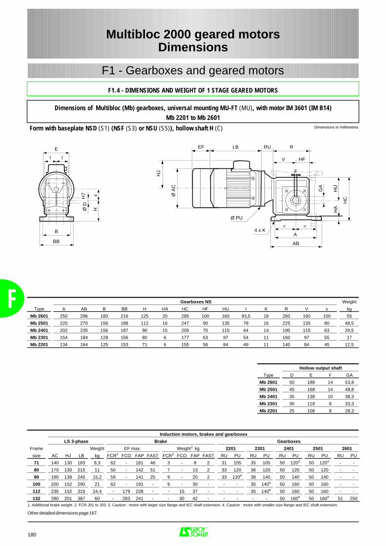
F
180
F1 - Gearboxes and geared motors
Dimensions in millimetresForm with baseplate NSD (S1) (NSF (S3) or NSU (S5)), hollow shaft H (C)
Multibloc 2000 geared motorsDimensions
F1.4 - DIMENSIONS AND WEIGHT OF 1 STAGE GEARED MOTORS
Dimensions of Multibloc (Mb) gearboxes, universal mounting MU-FT (MU), with motor IM 3601 (IM B14)Mb 2201 to Mb 2601
RU R
V
F
4 x K
HC
GA
==
A
AB
HU
HA
I I
E
B
BB
Ø D
H7 x
H
LBEF
HJ
Ø A
C
Ø PU
HF
Gearboxes NS Weight
Type A AB B BB H HA HC HF HU I K R V x kg
Mb 2601 250 296 180 216 125 20 285 100 160 93,5 18 260 160 100 55
Mb 2501 220 270 156 188 112 16 247 90 135 78 16 225 135 80 48,5
Mb 2401 202 235 156 187 90 15 205 75 115 64 14 190 115 63 29,5
Mb 2301 154 184 128 156 80 6 177 63 97 54 11 160 97 55 17
Mb 2201 134 164 125 153 71 6 155 56 84 49 11 140 84 45 12,5
Hollow output shaft
Type D E F GA
Mb 2601 50 188 14 53,8
Mb 2501 45 168 14 48,8
Mb 2401 35 138 10 38,3
Mb 2301 30 118 8 33,3
Mb 2201 25 108 8 28,3
Induction motors, brakes and gearboxes
LS 3-phase Brake Gearboxes
Frame Weight EF max. Weight1 kg 2201 2301 2401 2501 2601
size AC HJ LB kg FCR2 FCO FAP FAST FCR2 FCO FAP FAST RU PU RU PU RU PU RU PU RU PU
71 140 130 183 8,3 62 - 181 46 3 - 8 2 31 105 35 105 50 1203 50 1203 - -
80 170 130 215 11 50 - 142 51 7 - 13 2 33 120 36 120 50 120 50 120 - -
90 190 138 245 15,2 59 - 141 25 9 - 20 2 33 1204 38 140 50 140 50 140 - -
100 200 152 290 21 62 - 191 - 9 - 30 - - - 35 1404 50 160 50 160 - -
112 235 152 315 24,4 - 179 228 - - 15 37 - - - 35 1404 50 160 50 160 - -
132 280 201 387 60 - 283 241 - - 30 42 - - - - - 50 1604 50 1604 51 2501. Additional brake weight. 2. FCR J01 to J03. 3. Caution : motor with larger size flange and IEC shaft extension. 4. Caution : motor with smaller size flange and IEC shaft extension.
Other detailed dimensions page 167.
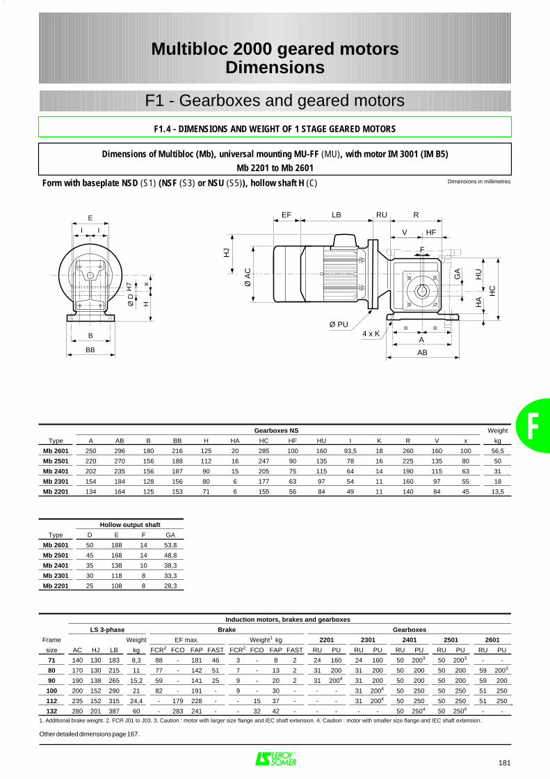
181
F1 - Gearboxes and geared motors
Dimensions in millimetresForm with baseplate NSD (S1) (NSF (S3) or NSU (S5)), hollow shaft H (C)
Multibloc 2000 geared motorsDimensions
F
F1.4 - DIMENSIONS AND WEIGHT OF 1 STAGE GEARED MOTORS
Dimensions of Multibloc (Mb), universal mounting MU-FF (MU), with motor IM 3001 (IM B5)Mb 2201 to Mb 2601
Gearboxes NS Weight
Type A AB B BB H HA HC HF HU I K R V x kg
Mb 2601 250 296 180 216 125 20 285 100 160 93,5 18 260 160 100 56,5
Mb 2501 220 270 156 188 112 16 247 90 135 78 16 225 135 80 50
Mb 2401 202 235 156 187 90 15 205 75 115 64 14 190 115 63 31
Mb 2301 154 184 128 156 80 6 177 63 97 54 11 160 97 55 18
Mb 2201 134 164 125 153 71 6 155 56 84 49 11 140 84 45 13,5
RU R
V
F
4 x K
HC
GA
==
A
AB
HU
HA
I I
E
B
BB
Ø D
H7 x
H
LBEF
HJ
Ø A
C
Ø PU
HF
Hollow output shaft
Type D E F GA
Mb 2601 50 188 14 53,8
Mb 2501 45 168 14 48,8
Mb 2401 35 138 10 38,3
Mb 2301 30 118 8 33,3
Mb 2201 25 108 8 28,3
Induction motors, brakes and gearboxes
LS 3-phase Brake Gearboxes
Frame Weight EF max. Weight1 kg 2201 2301 2401 2501 2601
size AC HJ LB kg FCR2 FCO FAP FAST FCR2 FCO FAP FAST RU PU RU PU RU PU RU PU RU PU
71 140 130 183 8,3 88 - 181 46 3 - 8 2 24 160 24 160 50 2003 50 2003 - -
80 170 130 215 11 77 - 142 51 7 - 13 2 31 200 31 200 50 200 50 200 59 2003
90 190 138 265 15,2 59 - 141 25 9 - 20 2 31 2004 31 200 50 200 50 200 59 200
100 200 152 290 21 82 - 191 - 9 - 30 - - - 31 2004 50 250 50 250 51 250
112 235 152 315 24,4 - 179 228 - - 15 37 - - - 31 2004 50 250 50 250 51 250
132 280 201 387 60 - 283 241 - - 32 42 - - - - - 50 2504 50 2504 - -1. Additional brake weight. 2. FCR J01 to J03. 3. Caution : motor with larger size flange and IEC shaft extension. 4. Caution : motor with smaller size flange and IEC shaft extension.
Other detailed dimensions page 167.
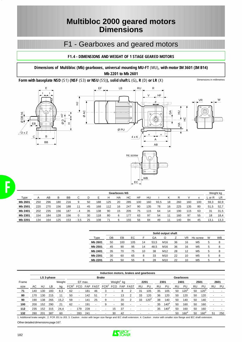
F
182
F1 - Gearboxes and geared motors
Dimensions in millimetresForm with baseplate NSD (S1) (NSF (S3) or NSU (S5)), solid shaft L (G), R (D) or LR (X)
Multibloc 2000 geared motorsDimensions
F1.4 - DIMENSIONS AND WEIGHT OF 1 STAGE GEARED MOTORS
Dimensions of Multibloc (Mb) gearboxes, universal mounting MU-FT (MU), with motor IM 3601 (IM B14)Mb 2201 to Mb 2601
RU R
V
F
4 x K
HC
GA
==
A
AB
HU
HA
I I
E
B
BB
Ø D
H7 x
H
LBEF
HJ
Ø A
C
Ø PU
HF
EB
C
Ø D
B h
6
O x Z
WB
Hc screw
EC
VR W
Gearboxes NS Weight kg
Type A AB B BB C D E H HA HC HF HU I K R V x L or R LR
Mb 2601 250 296 180 216 9 50 188 125 20 285 100 160 93,5 18 260 160 100 59,3 60,9
Mb 2501 220 270 156 188 11 45 168 112 16 247 90 135 78 16 225 135 80 51,5 52,7
Mb 2401 202 235 156 187 - 4 35 138 90 15 205 75 115 64 14 190 115 63 31 31,5
Mb 2301 154 184 128 156 0 30 118 80 6 177 63 97 54 11 160 97 55 18 18,4
Mb 2201 134 164 125 153 - 3,5 25 108 71 6 155 56 84 49 11 140 84 45 13,1 13,3
Solid output shaft
Type DB EB EC F GA O Z VR Hc screw W WB
Mb 2601 50 100 105 14 53,5 M16 36 16 M5 5 8
Mb 2501 45 90 95 14 48,5 M16 36 16 M5 5 8
Mb 2401 35 70 75 10 38 M12 28 12 M5 5 8
Mb 2301 30 60 65 8 33 M10 22 10 M5 5 8
Mb 2201 25 50 55 8 28 M10 22 10 M5 5 8
Induction motors, brakes and gearboxes
LS 3-phase Brake Gearboxes
Frame Weight EF max. Weight1 kg 2201 2301 2401 2501 2601
size AC HJ LB kg FCR2 FCO FAP FAST FCR2 FCO FAP FAST RU PU RU PU RU PU RU PU RU PU
71 140 130 183 8,3 62 - 181 46 3 - 8 2 31 105 35 105 50 1203 50 1203 - -
80 170 130 215 11 50 - 142 51 7 - 13 2 33 120 36 120 50 120 50 120 - -
90 190 138 265 15,2 59 - 141 25 9 - 20 2 33 1204 38 140 50 140 50 140 - -
100 200 152 290 21 62 - 191 - 9 - 30 - - - 35 1404 50 160 50 160 - -
112 235 152 315 24,4 - 179 228 - - 15 37 - - - 35 1404 50 160 50 160 - -
132 280 201 387 60 - 283 241 - - 30 42 - - - - - 50 1604 50 1604 51 2501. Additional brake weight.. 2. FCR J01 to J03. 3. Caution : motor with larger size flange and IEC shaft extension. 4. Caution : motor with smaller size flange and IEC shaft extension.
Other detailed dimensions page 167.
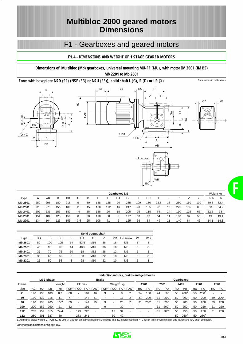
183
F1 - Gearboxes and geared motors
Dimensions in millimetresForm with baseplate NSD (S1) (NSF (S3) or NSU (S5)), solid shaft L (G), R (D) or LR (X)
Multibloc 2000 geared motorsDimensions
F
F1.4 - DIMENSIONS AND WEIGHT OF 1 STAGE GEARED MOTORS
Dimensions of Multibloc (Mb) gearboxes, universal mounting MU-FF (MU), with motor IM 3001 (IM B5)Mb 2201 to Mb 2601
RU R
V
F
4 x K
HC
GA
==
A
AB
HU
HA
I I
E
B
BB
fl D
H7 x
H
LBEF
HJ
fl A
C
fl PU
HF
EB
C
fl D
B h
6
O x Z
VR
WB
Hc screw
EC
W
Gearboxes NS Weight kg
Type A AB B BB C D E H HA HC HF HU I K R V x L or R LR
Mb 2601 250 296 180 216 9 50 188 125 20 285 100 160 93,5 18 260 160 100 60,8 62,4
Mb 2501 220 270 156 188 11 45 168 112 16 247 90 135 78 16 225 135 80 53 54,2
Mb 2401 202 235 156 187 - 4 35 138 90 15 205 75 115 64 14 190 115 63 32,5 33
Mb 2301 154 184 128 156 0 30 118 80 6 177 63 97 54 11 160 97 55 19 19,4
Mb 2201 134 164 125 153 - 3,5 25 108 71 6 155 56 84 49 11 140 84 45 14,1 14,3
Solid output shaft
Type DB EB EC F GA O Z VR Hc screw W WB
Mb 2601 50 100 105 14 53,5 M16 36 16 M5 5 8
Mb 2501 45 90 95 14 48,5 M16 36 16 M5 5 8
Mb 2401 35 70 75 10 38 M12 28 12 M5 5 8
Mb 2301 30 60 65 8 33 M10 22 10 M5 5 8
Mb 2201 25 50 55 8 28 M10 22 10 M5 5 8
Induction motors, brakes and gearboxes
LS 3-phase Brake Gearboxes
Frame Weight EF max. Weight1 kg 2201 2301 2401 2501 2601
size AC HJ LB kg FCR2 FCO FAP FAST FCR2 FCO FAP FAST RU PU RU PU RU PU RU PU RU PU
71 140 130 183 8,3 88 - 181 46 3 - 8 2 24 160 24 160 50 2003 50 2003 - -
80 170 130 215 11 77 - 142 51 7 - 13 2 31 200 31 200 50 200 50 200 59 2003
90 190 138 265 15,2 59 - 141 25 9 - 20 2 31 2004 31 200 50 200 50 200 59 200
100 200 152 290 21 82 - 191 - 9 - 30 - - - 31 2004 50 250 50 250 51 250
112 235 152 315 24,4 - 179 228 - - 15 37 - - - 31 2004 50 250 50 250 51 250
132 280 201 387 60 - 283 241 - - 30 42 - - - - - 50 2504 50 2504 - -1. Additional brake weight. 2. FCR J01 to J03. 3. Caution : motor with larger size flange and IEC shaft extension. 4. Caution : motor with smaller size flange and IEC shaft extension.
Other detailed dimensions page 167.
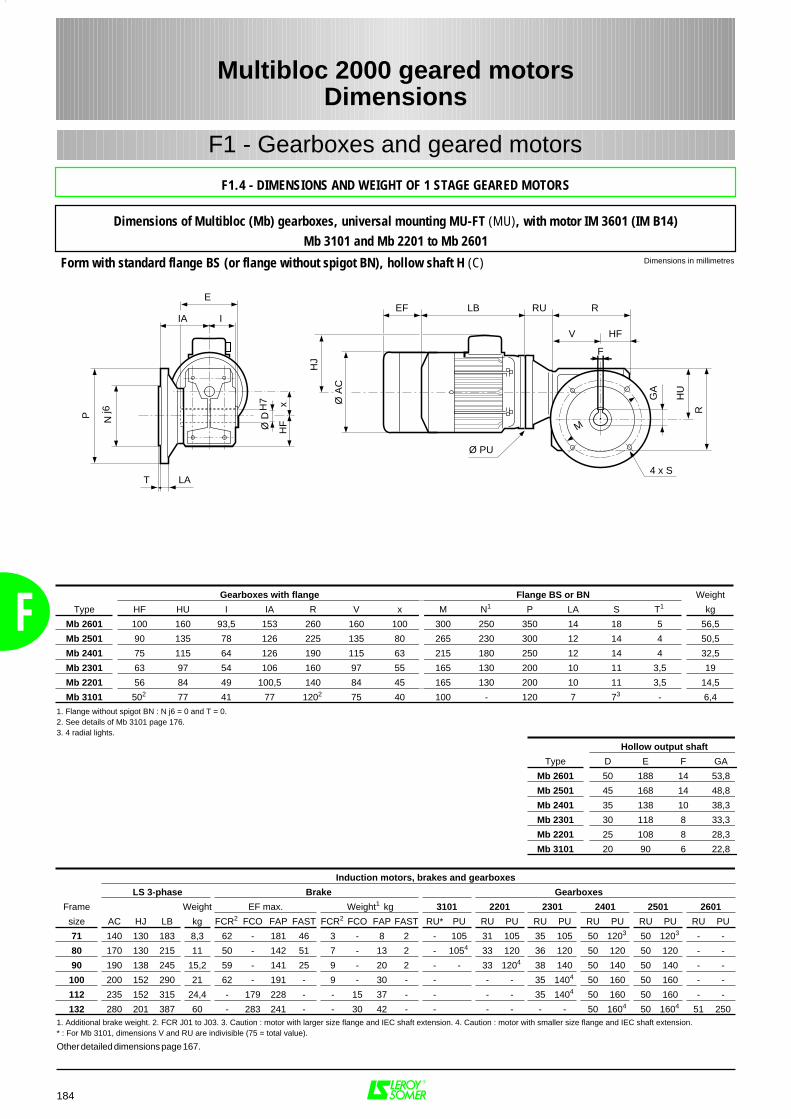
F
184
F1 - Gearboxes and geared motors
Dimensions in millimetresForm with standard flange BS (or flange without spigot BN), hollow shaft H (C)
Multibloc 2000 geared motorsDimensions
F1.4 - DIMENSIONS AND WEIGHT OF 1 STAGE GEARED MOTORS
Dimensions of Multibloc (Mb) gearboxes, universal mounting MU-FT (MU), with motor IM 3601 (IM B14)Mb 3101 and Mb 2201 to Mb 2601
RU R
4 x S
R
GA
LBEFH
J
Ø A
CF
V
Ø PU
HU
IA I
E
Ø D
H7 x
HF
T LA
P Nj6
M
HF
Gearboxes with flange Flange BS or BN Weight
Type HF HU I IA R V x M N1 P LA S T1 kg
Mb 2601 100 160 93,5 153 260 160 100 300 250 350 14 18 5 56,5
Mb 2501 90 135 78 126 225 135 80 265 230 300 12 14 4 50,5
Mb 2401 75 115 64 126 190 115 63 215 180 250 12 14 4 32,5
Mb 2301 63 97 54 106 160 97 55 165 130 200 10 11 3,5 19
Mb 2201 56 84 49 100,5 140 84 45 165 130 200 10 11 3,5 14,5
Mb 3101 502 77 41 77 1202 75 40 100 - 120 7 73 - 6,4
Induction motors, brakes and gearboxes
LS 3-phase Brake Gearboxes
Frame Weight EF max. Weight1 kg 3101 2201 2301 2401 2501 2601
size AC HJ LB kg FCR2 FCO FAP FAST FCR2 FCO FAP FAST RU* PU RU PU RU PU RU PU RU PU RU PU
71 140 130 183 8,3 62 - 181 46 3 - 8 2 - 105 31 105 35 105 50 1203 50 1203 - -
80 170 130 215 11 50 - 142 51 7 - 13 2 - 1054 33 120 36 120 50 120 50 120 - -
90 190 138 245 15,2 59 - 141 25 9 - 20 2 - - 33 1204 38 140 50 140 50 140 - -
100 200 152 290 21 62 - 191 - 9 - 30 - - - - 35 1404 50 160 50 160 - -
112 235 152 315 24,4 - 179 228 - - 15 37 - - - - 35 1404 50 160 50 160 - -
132 280 201 387 60 - 283 241 - - 30 42 - - - - - - 50 1604 50 1604 51 2501. Additional brake weight. 2. FCR J01 to J03. 3. Caution : motor with larger size flange and IEC shaft extension. 4. Caution : motor with smaller size flange and IEC shaft extension.* : For Mb 3101, dimensions V and RU are indivisible (75 = total value).
Other detailed dimensions page 167.
1. Flange without spigot BN : N j6 = 0 and T = 0.2. See details of Mb 3101 page 176.3. 4 radial lights.
Hollow output shaft
Type D E F GA
Mb 2601 50 188 14 53,8
Mb 2501 45 168 14 48,8
Mb 2401 35 138 10 38,3
Mb 2301 30 118 8 33,3
Mb 2201 25 108 8 28,3
Mb 3101 20 90 6 22,8

185
F1 - Gearboxes and geared motors
Dimensions in millimetresForm with standard flange BS (ou flange without spigot BN), hollow shaft H (C)
Multibloc 2000 geared motorsDimensions
F
F1.4 - DIMENSIONS AND WEIGHT OF 1 STAGE GEARED MOTORS
Dimensions of Multibloc (Mb) gearboxes, universal mounting MU-FF (MU), with motor IM 3001 (IM B5)Mb 2201 to Mb 2601
LB
Ø D
H7
I A I
E
xH
F
T LA
P Nj6
HJ
Ø A
C
4 x S
R
GA
Ø PU
HU
M
RU REF
F
V HF
Induction motors, brakes and gearboxes
LS 3-phase Brake Gearboxes
Frame Weight EF max. Weight1 kg 2201 2301 2401 2501 2601
size AC HJ LB kg FCR2 FCO FAP FAST FCR2 FCO FAP FAST RU PU RU PU RU PU RU PU RU PU
71 140 130 183 8,3 88 - 181 46 3 - 8 2 24 160 24 160 50 2003 50 2003 - -
80 170 130 215 11 77 - 142 51 7 - 13 2 31 200 31 200 50 200 50 200 59 2003
90 190 138 265 15,2 59 - 141 25 9 - 20 2 31 2004 31 200 50 200 50 200 59 200
100 200 152 290 21 82 - 191 - 9 - 30 - - - 31 2004 50 250 50 250 51 250
112 235 152 315 24,4 - 179 228 - - 15 37 - - - 31 2004 50 250 50 250 51 250
132 280 201 387 60 - 283 241 - - 30 42 - - - - - 50 2504 50 2504 - -
Gearboxes with flange Flange BS or BN WeightType HF HU I IA R V x M N1 P LA S T1 kg
Mb 2601 100 160 93,5 153 260 160 100 300 250 350 14 18 5 58
Mb 2501 90 135 78 126 225 135 80 265 230 300 12 14 4 52
Mb 2401 75 115 64 126 190 115 63 215 180 250 12 14 4 34
Mb 2301 63 97 54 106 160 97 55 165 130 200 10 11 3,5 20
Mb 2201 56 84 49 100,5 140 84 45 165 130 200 10 11 3,5 15,5
1. Additional brake weight. 2. FCR J01 to J03. 3. Caution : motor with larger size flange and IEC shaft extension. 4. Caution : motor with smaller size flange and IEC shaft extension.
Hollow output shaftType D E F GA
Mb 2601 50 188 14 53,8
Mb 2501 45 168 14 48,8
Mb 2401 35 138 10 38,3
Mb 2301 30 118 8 33,3
Mb 2201 25 108 8 28,3
Other detailed dimensions page 167.
1. Flange without spigot BN : N j6 = 0 and T = 0.
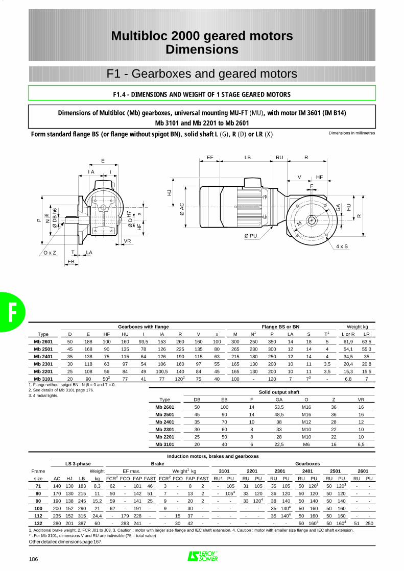
F
186
F1 - Gearboxes and geared motors
Dimensions in millimetresForm standard flange BS (or flange without spigot BN), solid shaft L (G), R (D) or LR (X)
Multibloc 2000 geared motorsDimensions
F1.4 - DIMENSIONS AND WEIGHT OF 1 STAGE GEARED MOTORS
Dimensions of Multibloc (Mb) gearboxes, universal mounting MU-FT (MU), with motor IM 3601 (IM B14)Mb 3101 and Mb 2201 to Mb 2601
RU R
4 x S
R
GA
LBEF
HJ
Ø A
CF
V
Ø PU
HU
M
HF
P Nj6
Ø D
B h
6
O x Z T LA
EB
I A I
E
VR
Ø D
H7 x
HF
Induction motors, brakes and gearboxes
LS 3-phase Brake Gearboxes
Frame Weight EF max. Weight1 kg 3101 2201 2301 2401 2501 2601
size AC HJ LB kg FCR2 FCO FAP FAST FCR2 FCO FAP FAST RU* PU RU PU RU PU RU PU RU PU RU PU
71 140 130 183 8,3 62 - 181 46 3 - 8 2 - 105 31 105 35 105 50 1203 50 1203 - -
80 170 130 215 11 50 - 142 51 7 - 13 2 - 1054 33 120 36 120 50 120 50 120 - -
90 190 138 245 15,2 59 - 141 25 9 - 20 2 - - 33 1204 38 140 50 140 50 140 - -
100 200 152 290 21 62 - 191 - 9 - 30 - - - - - 35 1404 50 160 50 160 - -
112 235 152 315 24,4 - 179 228 - - 15 37 - - - - - 35 1404 50 160 50 160 - -
132 280 201 387 60 - 283 241 - - 30 42 - - - - - - - 50 1604 50 1604 51 250
-1. Additional brake weight. 2. FCR J01 to J03. 3. Caution : motor with larger size flange and IEC shaft extension. 4. Caution : motor with smaller size flange and IEC shaft extension.* : For Mb 3101, dimensions V and RU are indivisible (75 = total value)
Other detailed dimensions page 167.
Gearboxes with flange Flange BS or BN Weight kg
Type D E HF HU I IA R V x M N1 P LA S T1 L or R LR
Mb 2601 50 188 100 160 93,5 153 260 160 100 300 250 350 14 18 5 61,9 63,5
Mb 2501 45 168 90 135 78 126 225 135 80 265 230 300 12 14 4 54,1 55,3
Mb 2401 35 138 75 115 64 126 190 115 63 215 180 250 12 14 4 34,5 35
Mb 2301 30 118 63 97 54 106 160 97 55 165 130 200 10 11 3,5 20,4 20,8
Mb 2201 25 108 56 84 49 100,5 140 84 45 165 130 200 10 11 3,5 15,3 15,5
Mb 3101 20 90 502 77 41 77 1202 75 40 100 - 120 7 73 - 6,8 71. Flange without spigot BN : N j6 = 0 and T = 0.2. See details of Mb 3101 page 176.3. 4 radial lights.
Solid output shaft
Type DB EB F GA O Z VR
Mb 2601 50 100 14 53,5 M16 36 16
Mb 2501 45 90 14 48,5 M16 36 16
Mb 2401 35 70 10 38 M12 28 12
Mb 2301 30 60 8 33 M10 22 10
Mb 2201 25 50 8 28 M10 22 10
Mb 3101 20 40 6 22,5 M6 16 6,5
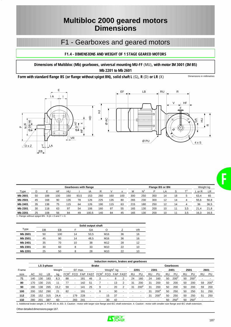
187
F1 - Gearboxes and geared motors
Dimensions in millimetresForm with standard flange BS (or flange without spigot BN), solid shaft L (G), R (D) or LR (X)
Multibloc 2000 geared motorsDimensions
F
F1.4 - DIMENSIONS AND WEIGHT OF 1 STAGE GEARED MOTORS
Dimensions of Multibloc (Mb) gearboxes, universal mounting MU-FF (MU), with motor IM 3001 (IM B5)Mb 2201 to Mb 2601
HD
I A I
E
P Nj6
Ø D
B h
6
O x Z T LA
EB
VR
Ø D
H7 x
HF
RU R
4 x S
R
GA
LBEF
HJ
Ø A
CF
V
Ø PU
HU
M
HF
Solid output shaftType DB EB F GA O Z VR
Mb 2601 50 100 14 53,5 M16 36 16
Mb 2501 45 90 14 48,5 M16 36 16
Mb 2401 35 70 10 38 M12 28 12
Mb 2301 30 60 8 33 M10 22 10
Mb 2201 25 50 8 28 M10 22 10
Induction motors, brakes and gearboxes
LS 3-phase Brake Gearboxes
Frame Weight EF max. Weight1 kg 2201 2301 2401 2501 2601
size AC HJ LB kg FCR2 FCO FAP FAST FCR2 FCO FAP FAST RU PU RU PU RU PU RU PU RU PU
71 140 130 183 8,3 88 - 181 46 3 - 8 2 24 160 24 160 50 2003 50 2003 - -
80 170 130 215 11 77 - 142 51 7 - 13 2 31 200 31 200 50 200 50 200 59 2003
90 190 138 265 15,2 59 - 141 25 9 - 20 2 31 2004 31 200 50 200 50 200 59 200
100 200 152 290 21 82 - 191 - 9 - 30 - - - 31 2004 50 250 50 250 51 250
112 235 152 315 24,4 - 179 228 - - 15 37 - - - 31 2004 50 250 50 250 51 250
132 280 201 387 60 - 283 241 - - 30 42 - - - - - 50 2504 50 2504 - -
Gearboxes with flange Flange BS or BN Weight kg
Type D E HF HU I IA R V x M N1 P LA S T1 L or R LR
Mb 2601 50 188 100 160 93,5 153 260 160 100 300 250 350 14 18 5 63,4 65
Mb 2501 45 168 90 135 78 126 225 135 80 265 230 300 12 14 4 55,6 56,8
Mb 2401 35 138 75 115 64 126 190 115 63 215 180 250 12 14 4 36 36,5
Mb 2301 30 118 63 97 54 106 160 97 55 165 130 200 10 11 3,5 21,4 21,8
Mb 2201 25 108 56 84 49 100,5 140 84 45 165 130 200 10 11 3,5 16,3 16,51. Flange without spigot BN : N j6 = 0 and T = 0.
1. Additional brake weight. 2. FCR J01 to J03. 3. Caution : motor with larger size flange and IEC shaft extension. 4. Caution : motor with smaller size flange and IEC shaft extension.
Other detailed dimensions page 167.
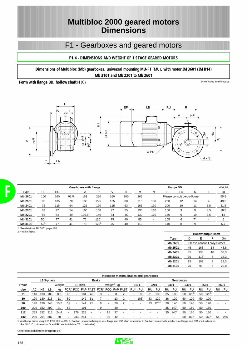
F
188
F1 - Gearboxes and geared motors
Dimensions in millimetresForm with flange BD, hollow shaft H (C)
Multibloc 2000 geared motorsDimensions
F1.4 - DIMENSIONS AND WEIGHT OF 1 STAGE GEARED MOTORS
Dimensions of Multibloc (Mb) gearboxes, universal mounting MU-FT (MU), with motor IM 3601 (IM B14)Mb 3101 and Mb 2201 to Mb 2601
RU R
4 x S
R
GA
LBEF
HJ
Ø A
C
F
V
Ø PU
HU
IA I
E
Ø D
H7 x
HF
T LA
P Nj6
M
HF
Gearboxes with flange Flange BD Weight
Type HF HU I IA R V x M N P LA S T kg
Mb 2601 100 160 93,5 153 260 160 100 265 Please consult Leroy-Somer 55,5
Mb 2501 90 135 78 138 225 135 80 215 180 250 12 14 4 49,5
Mb 2401 75 115 64 126 190 115 63 165 130 200 10 11 3,5 31,5
Mb 2301 63 97 54 106 160 97 55 130 110 160 9 9 3,5 18,5
Mb 2201 56 84 49 100,5 140 84 45 130 110 160 9 10 3,5 14
Mb 3101 501 77 41 76 1201 75 40 85 - 105 6 72 - 6
Mb 3101 501 77 41 79 1201 75 40 115 - 140 8 9 - 6,7
Induction motors, brakes and gearboxes
LS 3-phase Brake Gearboxes
Frame Weight EF max. Weight1 kg 3101 2201 2301 2401 2501 2601
size AC HJ LB kg FCR2 FCO FAP FAST FCR2 FCO FAP FAST RU* PU RU PU RU PU RU PU RU PU RU PU
71 140 130 183 8,3 62 - 181 46 3 - 8 2 - 105 31 105 35 105 50 1203 50 1203 - -
80 170 130 215 11 50 - 142 51 7 - 13 2 - 1054 33 120 36 120 50 120 50 120 - -
90 190 138 245 15,2 59 - 141 25 9 - 20 2 - - 33 1204 38 140 50 140 50 140 - -
100 200 152 290 21 62 - 191 - 9 - 30 - - - - - 35 1404 50 160 50 160 - -
112 235 152 315 24,4 - 179 228 - - 15 37 - - - - - 35 1404 50 160 50 160 - -
132 280 201 387 60 - 283 241 - - 30 42 - - - - - - - 50 1604 50 1604 51 2501. Additional brake weight. 2. FCR J01 to J03. 3. Caution : motor with larger size flange and IEC shaft extension. 4. Caution : motor with smaller size flange and IEC shaft extension.* : For Mb 3101, dimensions V and RU are indivisible (75 = total value)
Hollow output shaft
Type D E F GA
Mb 2601 Please consult Leroy-Somer
Mb 2501 45 168 14 48,8
Mb 2401 35 138 10 38,3
Mb 2301 30 118 8 33,3
Mb 2201 25 108 8 28,3
Mb 3101 20 90 6 22,8
Other detailed dimensions page 167.
1. See details of Mb 3101 page 176.2. 4 radial lights.
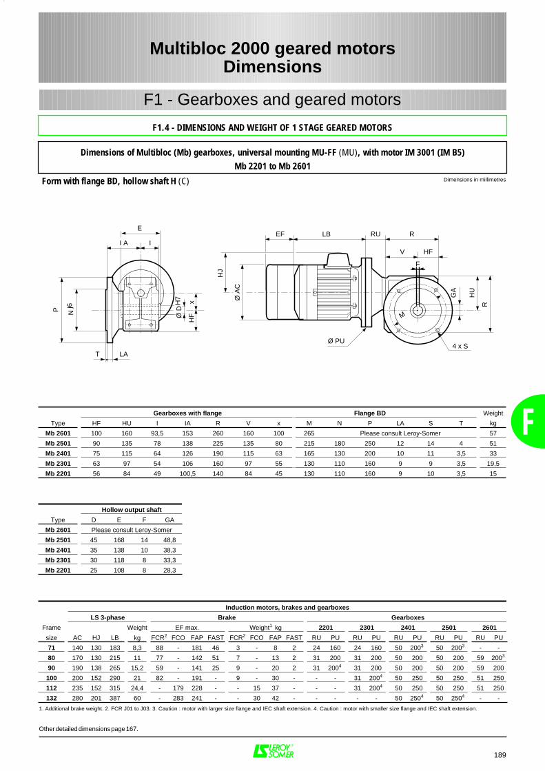
189
F1 - Gearboxes and geared motors
Dimensions in millimetresForm with flange BD, hollow shaft H (C)
Multibloc 2000 geared motorsDimensions
F
F1.4 - DIMENSIONS AND WEIGHT OF 1 STAGE GEARED MOTORS
Dimensions of Multibloc (Mb) gearboxes, universal mounting MU-FF (MU), with motor IM 3001 (IM B5)Mb 2201 to Mb 2601
LB
Ø D
H7
I A I
E
xH
F
T LA
P Nj6
HJ
Ø A
C
4 x S
R
GA
Ø PU
HU
M
RU REF
F
V HF
Induction motors, brakes and gearboxes
LS 3-phase Brake Gearboxes
Frame Weight EF max. Weight1 kg 2201 2301 2401 2501 2601
size AC HJ LB kg FCR2 FCO FAP FAST FCR2 FCO FAP FAST RU PU RU PU RU PU RU PU RU PU
71 140 130 183 8,3 88 - 181 46 3 - 8 2 24 160 24 160 50 2003 50 2003 - -
80 170 130 215 11 77 - 142 51 7 - 13 2 31 200 31 200 50 200 50 200 59 2003
90 190 138 265 15,2 59 - 141 25 9 - 20 2 31 2004 31 200 50 200 50 200 59 200
100 200 152 290 21 82 - 191 - 9 - 30 - - - 31 2004 50 250 50 250 51 250
112 235 152 315 24,4 - 179 228 - - 15 37 - - - 31 2004 50 250 50 250 51 250
132 280 201 387 60 - 283 241 - - 30 42 - - - - - 50 2504 50 2504 - -
Gearboxes with flange Flange BD Weight
Type HF HU I IA R V x M N P LA S T kg
Mb 2601 100 160 93,5 153 260 160 100 265 Please consult Leroy-Somer 57
Mb 2501 90 135 78 138 225 135 80 215 180 250 12 14 4 51
Mb 2401 75 115 64 126 190 115 63 165 130 200 10 11 3,5 33
Mb 2301 63 97 54 106 160 97 55 130 110 160 9 9 3,5 19,5
Mb 2201 56 84 49 100,5 140 84 45 130 110 160 9 10 3,5 15
1. Additional brake weight. 2. FCR J01 to J03. 3. Caution : motor with larger size flange and IEC shaft extension. 4. Caution : motor with smaller size flange and IEC shaft extension.
Hollow output shaft
Type D E F GA
Mb 2601 Please consult Leroy-Somer
Mb 2501 45 168 14 48,8
Mb 2401 35 138 10 38,3
Mb 2301 30 118 8 33,3
Mb 2201 25 108 8 28,3
Other detailed dimensions page 167.
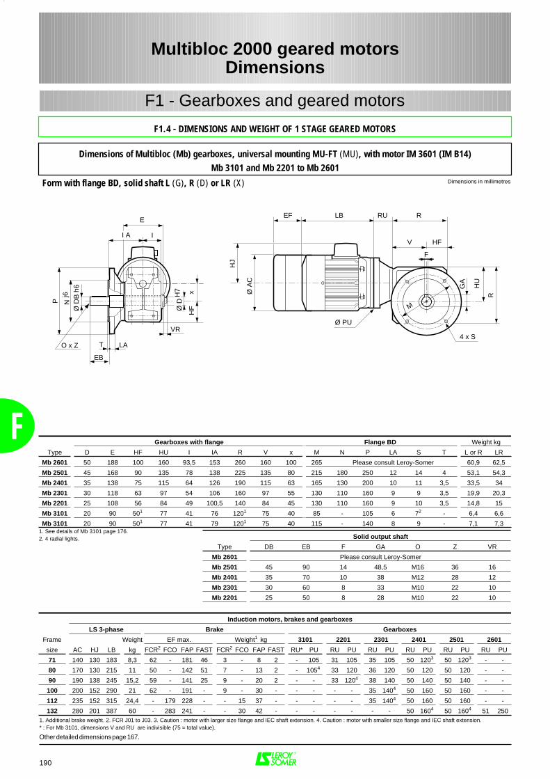
F
190
F1 - Gearboxes and geared motors
Dimensions in millimetresForm with flange BD, solid shaft L (G), R (D) or LR (X)
Multibloc 2000 geared motorsDimensions
F1.4 - DIMENSIONS AND WEIGHT OF 1 STAGE GEARED MOTORS
Dimensions of Multibloc (Mb) gearboxes, universal mounting MU-FT (MU), with motor IM 3601 (IM B14)Mb 3101 and Mb 2201 to Mb 2601
RU R
4 x S
R
GA
LBEF
HJ
Ø A
CF
V
Ø PU
HU
M
HF
P Nj6
Ø D
B h
6
O x Z T LA
EB
I A I
E
VR
Ø D
H7 x
HF
Solid output shaft
Type DB EB F GA O Z VR
Mb 2601 Please consult Leroy-Somer
Mb 2501 45 90 14 48,5 M16 36 16
Mb 2401 35 70 10 38 M12 28 12
Mb 2301 30 60 8 33 M10 22 10
Mb 2201 25 50 8 28 M10 22 10
Induction motors, brakes and gearboxes
LS 3-phase Brake Gearboxes
Frame Weight EF max. Weight1 kg 3101 2201 2301 2401 2501 2601
size AC HJ LB kg FCR2 FCO FAP FAST FCR2 FCO FAP FAST RU* PU RU PU RU PU RU PU RU PU RU PU
71 140 130 183 8,3 62 - 181 46 3 - 8 2 - 105 31 105 35 105 50 1203 50 1203 - -
80 170 130 215 11 50 - 142 51 7 - 13 2 - 1054 33 120 36 120 50 120 50 120 - -
90 190 138 245 15,2 59 - 141 25 9 - 20 2 - - 33 1204 38 140 50 140 50 140 - -
100 200 152 290 21 62 - 191 - 9 - 30 - - - - - 35 1404 50 160 50 160 - -
112 235 152 315 24,4 - 179 228 - - 15 37 - - - - - 35 1404 50 160 50 160 - -
132 280 201 387 60 - 283 241 - - 30 42 - - - - - - - 50 1604 50 1604 51 250
Gearboxes with flange Flange BD Weight kg
Type D E HF HU I IA R V x M N P LA S T L or R LR
Mb 2601 50 188 100 160 93,5 153 260 160 100 265 Please consult Leroy-Somer 60,9 62,5
Mb 2501 45 168 90 135 78 138 225 135 80 215 180 250 12 14 4 53,1 54,3
Mb 2401 35 138 75 115 64 126 190 115 63 165 130 200 10 11 3,5 33,5 34
Mb 2301 30 118 63 97 54 106 160 97 55 130 110 160 9 9 3,5 19,9 20,3
Mb 2201 25 108 56 84 49 100,5 140 84 45 130 110 160 9 10 3,5 14,8 15
Mb 3101 20 90 501 77 41 76 1201 75 40 85 - 105 6 72 - 6,4 6,6
Mb 3101 20 90 501 77 41 79 1201 75 40 115 - 140 8 9 - 7,1 7,31. See details of Mb 3101 page 176.2. 4 radial lights.
1. Additional brake weight. 2. FCR J01 to J03. 3. Caution : motor with larger size flange and IEC shaft extension. 4. Caution : motor with smaller size flange and IEC shaft extension.* : For Mb 3101, dimensions V and RU are indivisible (75 = total value).
Other detailed dimensions page 167.
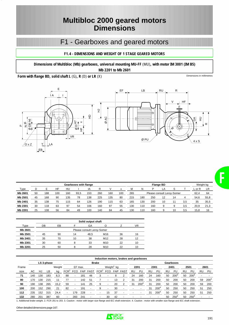
191
F1 - Gearboxes and geared motors
Dimensions in millimetresForm with flange BD, solid shaft L (G), R (D) or LR (X)
Multibloc 2000 geared motorsDimensions
F
F1.4 - DIMENSIONS AND WEIGHT OF 1 STAGE GEARED MOTORS
Dimensions of Multibloc (Mb) gearboxes, universal mounting MU-FF (MU), with motor IM 3001 (IM B5)Mb 2201 to Mb 2601
HD
I A I
E
P Nj6
Ø D
B h
6
O x Z T LA
EB
VR
Ø D
H7 x
HF
RU R
4 x S
R
GA
LBEF
HJ
Ø A
CF
V
Ø PU
HU
M
HF
Solid output shaft
Type DB EB F GA O Z VR
Mb 2601 Please consult Leroy-Somer
Mb 2501 45 90 14 48,5 M16 36 16
Mb 2401 35 70 10 38 M12 28 12
Mb 2301 30 60 8 33 M10 22 10
Mb 2201 25 50 8 28 M10 22 10
Induction motors, brakes and gearboxes
LS 3-phase Brake Gearboxes
Frame Weight EF max. Weight1 kg 2201 2301 2401 2501 2601
size AC HJ LB kg FCR2 FCO FAP FAST FCR2 FCO FAP FAST RU PU RU PU RU PU RU PU RU PU
71 140 130 183 8,3 88 - 181 46 3 - 8 2 24 160 24 160 50 2003 50 2003 - -
80 170 130 215 11 77 - 142 51 7 - 13 2 31 200 31 200 50 200 50 200 59 2003
90 190 138 265 15,2 59 - 141 25 9 - 20 2 31 2004 31 200 50 200 50 200 59 200
100 200 152 290 21 82 - 191 - 9 - 30 - - - 31 2004 50 250 50 250 51 250
112 235 152 315 24,4 - 179 228 - - 15 37 - - - 31 2004 50 250 50 250 51 250
132 280 201 387 60 - 283 241 - - 30 42 - - - - - 50 2504 50 2504 - -
Gearboxes with flange Flange BD Weight kg
Type D E HF HU I IA R V x M N P LA S T L or R LR
Mb 2601 50 188 100 160 93,5 153 260 160 100 265 Please consult Leroy-Somer 62,4 64
Mb 2501 45 168 90 135 78 138 225 135 80 215 180 250 12 14 4 54,6 55,8
Mb 2401 35 138 75 115 64 126 190 115 63 165 130 200 10 11 3,5 35 35,5
Mb 2301 30 118 63 97 54 106 160 97 55 130 110 160 9 9 3,5 20,9 21,3
Mb 2201 25 108 56 84 49 100 140 84 45 130 110 160 9 10 3,5 15,8 16
1. Additional brake weight. 2. FCR J01 to J03. 3. Caution : motor with larger size flange and IEC shaft extension. 4. Caution : motor with smaller size flange and IEC shaft extension.
Other detailed dimensions page 167.
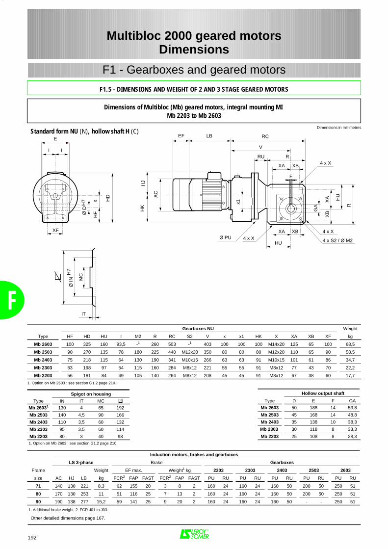
RC
V
XB 4 x X
F
4 x X4 x X
4 x S2 / Ø M2
R
XA
XBG
A
XA XB
XA
Ø PU
I I
E
xH
F
XF
LBEF
AC
HJ
HD
x1
HU
HU
RU R
HK
IT
Ø IN
H7
MC
Ø D
H7
Spigot on housing
Type IN IT MC
Mb 26031 130 4 65 192
Mb 2503 140 4,5 90 166
Mb 2403 110 3,5 60 132
Mb 2303 95 3,5 60 114
Mb 2203 80 3 40 981. Option on Mb 2603 : see section G1.2 page 210.
Gearboxes NU Weight
Type HF HD HU I M2 R RC S2 V x x1 HK X XA XB XF kg
Mb 2603 100 325 160 93,5 -1 260 503 -1 403 100 100 100 M14x20 125 65 100 68,5
Mb 2503 90 270 135 78 180 225 440 M12x20 350 80 80 80 M12x20 110 65 90 58,5
Mb 2403 75 218 115 64 130 190 341 M10x15 266 63 63 91 M10x15 101 61 86 34,7
Mb 2303 63 198 97 54 115 160 284 M8x12 221 55 55 91 M8x12 77 43 70 22,2
Mb 2203 56 181 84 49 105 140 264 M8x12 208 45 45 91 M8x12 67 38 60 17,7
1. Option on Mb 2603 : see section G1.2 page 210.
Induction motors, brakes and gearboxes
LS 3-phase Brake Gearboxes
Frame Weight EF max. Weight1 kg 2203 2303 2403 2503 2603
size AC HJ LB kg FCR2 FAP FAST FCR2 FAP FAST PU RU PU RU PU RU PU RU PU RU
71 140 130 221 8,3 62 155 20 3 8 2 160 24 160 24 160 50 200 50 250 51
80 170 130 253 11 51 116 25 7 13 2 160 24 160 24 160 50 200 50 250 51
90 190 138 277 15,2 59 141 25 9 20 2 160 24 160 24 160 50 - - 250 51
1. Additional brake weight. 2. FCR J01 to J03.
Hollow output shaft
Type D E F GA
Mb 2603 50 188 14 53,8
Mb 2503 45 168 14 48,8
Mb 2403 35 138 10 38,3
Mb 2303 30 118 8 33,3
Mb 2203 25 108 8 28,3
F
Other detailed dimensions page 167.
Multibloc 2000 geared motorsDimensions
F1 - Gearboxes and geared motors
Dimensions of Multibloc (Mb) geared motors, integral mounting MI Mb 2203 to Mb 2603
Dimensions in millimetres
192
F1.5 - DIMENSIONS AND WEIGHT OF 2 AND 3 STAGE GEARED MOTORS
Standard form NU (N), hollow shaft H (C)
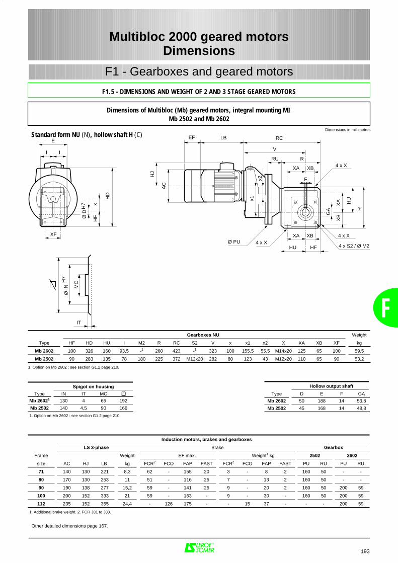
F
RC
V
XB 4 x X
F
4 x X4 x X
R
XA
XBG
A
XA XB
XA
Ø PU
I I
E
xH
F
XF
LBEF
AC
HJ
HD
x1
HU
HU
RU R
x2
HF
IT
Ø IN
H7
MC
4 x S2 / Ø M2
Ø D
H7
Spigot on housing
Type IN IT MC
Mb 26021 130 4 65 192
Mb 2502 140 4,5 90 166
1. Option on Mb 2602 : see section G1.2 page 210.
Gearboxes NU Weight
Type HF HD HU I M2 R RC S2 V x x1 x2 X XA XB XF kg
Mb 2602 100 326 160 93,5 -1 260 423 -1 323 100 155,5 55,5 M14x20 125 65 100 59,5
Mb 2502 90 283 135 78 180 225 372 M12x20 282 80 123 43 M12x20 110 65 90 53,2
1. Option on Mb 2602 : see section G1.2 page 210.
Induction motors, brakes and gearboxes
LS 3-phase Brake Gearbox
Frame Weight EF max. Weight1 kg 2502 2602
size AC HJ LB kg FCR2 FCO FAP FAST FCR2 FCO FAP FAST PU RU PU RU
71 140 130 221 8,3 62 - 155 20 3 - 8 2 160 50 - -
80 170 130 253 11 51 - 116 25 7 - 13 2 160 50 - -
90 190 138 277 15,2 59 - 141 25 9 - 20 2 160 50 200 59
100 200 152 333 21 59 - 163 - 9 - 30 - 160 50 200 59
112 235 152 355 24,4 - 126 175 - - 15 37 - - - 200 59
1. Additional brake weight. 2. FCR J01 to J03.
Hollow output shaft
Type D E F GA
Mb 2602 50 188 14 53,8
Mb 2502 45 168 14 48,8
Other detailed dimensions page 167.
Multibloc 2000 geared motorsDimensions
193
F1 - Gearboxes and geared motors
Dimensions of Multibloc (Mb) geared motors, integral mounting MI Mb 2502 and Mb 2602
Dimensions in millimetres
F1.5 - DIMENSIONS AND WEIGHT OF 2 AND 3 STAGE GEARED MOTORS
Standard form NU (N), hollow shaft H (C)
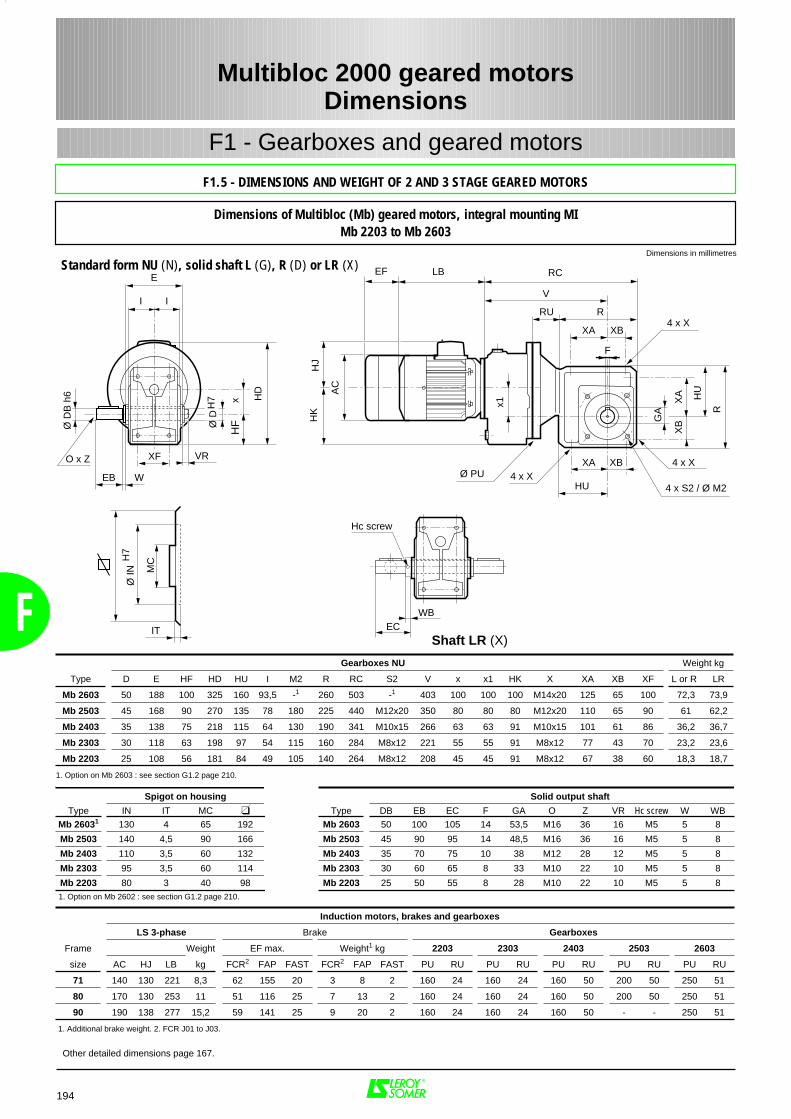
F
RC
V
XB4 x X
F
4 x X4 x X
4 x S2 / Ø M2
R
XA
XBG
A
XA XB
XA
Ø PU
I I
E
xH
F
XF
LBEF
AC
HJ
HD
x1
HU
HU
RU RH
K
EB W
Ø D
B h
6
O x Z VR
IT
Ø IN
H7
MC
WB
Hc screw
EC
Ø D
H7
Spigot on housing
Type IN IT MC
Mb 26031 130 4 65 192
Mb 2503 140 4,5 90 166
Mb 2403 110 3,5 60 132
Mb 2303 95 3,5 60 114
Mb 2203 80 3 40 981. Option on Mb 2602 : see section G1.2 page 210.
Gearboxes NU Weight kg
Type D E HF HD HU I M2 R RC S2 V x x1 HK X XA XB XF L or R LR
Mb 2603 50 188 100 325 160 93,5 -1 260 503 -1 403 100 100 100 M14x20 125 65 100 72,3 73,9
Mb 2503 45 168 90 270 135 78 180 225 440 M12x20 350 80 80 80 M12x20 110 65 90 61 62,2
Mb 2403 35 138 75 218 115 64 130 190 341 M10x15 266 63 63 91 M10x15 101 61 86 36,2 36,7
Mb 2303 30 118 63 198 97 54 115 160 284 M8x12 221 55 55 91 M8x12 77 43 70 23,2 23,6
Mb 2203 25 108 56 181 84 49 105 140 264 M8x12 208 45 45 91 M8x12 67 38 60 18,3 18,7
1. Option on Mb 2603 : see section G1.2 page 210.
Induction motors, brakes and gearboxes
LS 3-phase Brake Gearboxes
Frame Weight EF max. Weight1 kg 2203 2303 2403 2503 2603
size AC HJ LB kg FCR2 FAP FAST FCR2 FAP FAST PU RU PU RU PU RU PU RU PU RU
71 140 130 221 8,3 62 155 20 3 8 2 160 24 160 24 160 50 200 50 250 51
80 170 130 253 11 51 116 25 7 13 2 160 24 160 24 160 50 200 50 250 51
90 190 138 277 15,2 59 141 25 9 20 2 160 24 160 24 160 50 - - 250 51
1. Additional brake weight. 2. FCR J01 to J03.
Solid output shaft
Type DB EB EC F GA O Z VR Hc screw W WB
Mb 2603 50 100 105 14 53,5 M16 36 16 M5 5 8
Mb 2503 45 90 95 14 48,5 M16 36 16 M5 5 8
Mb 2403 35 70 75 10 38 M12 28 12 M5 5 8
Mb 2303 30 60 65 8 33 M10 22 10 M5 5 8
Mb 2203 25 50 55 8 28 M10 22 10 M5 5 8
Other detailed dimensions page 167.
Multibloc 2000 geared motorsDimensions
194
F1 - Gearboxes and geared motors
Dimensions of Multibloc (Mb) geared motors, integral mounting MIMb 2203 to Mb 2603
Dimensions in millimetres
F1.5 - DIMENSIONS AND WEIGHT OF 2 AND 3 STAGE GEARED MOTORS
Standard form NU (N), solid shaft L (G), R (D) or LR (X)
Shaft LR (X)
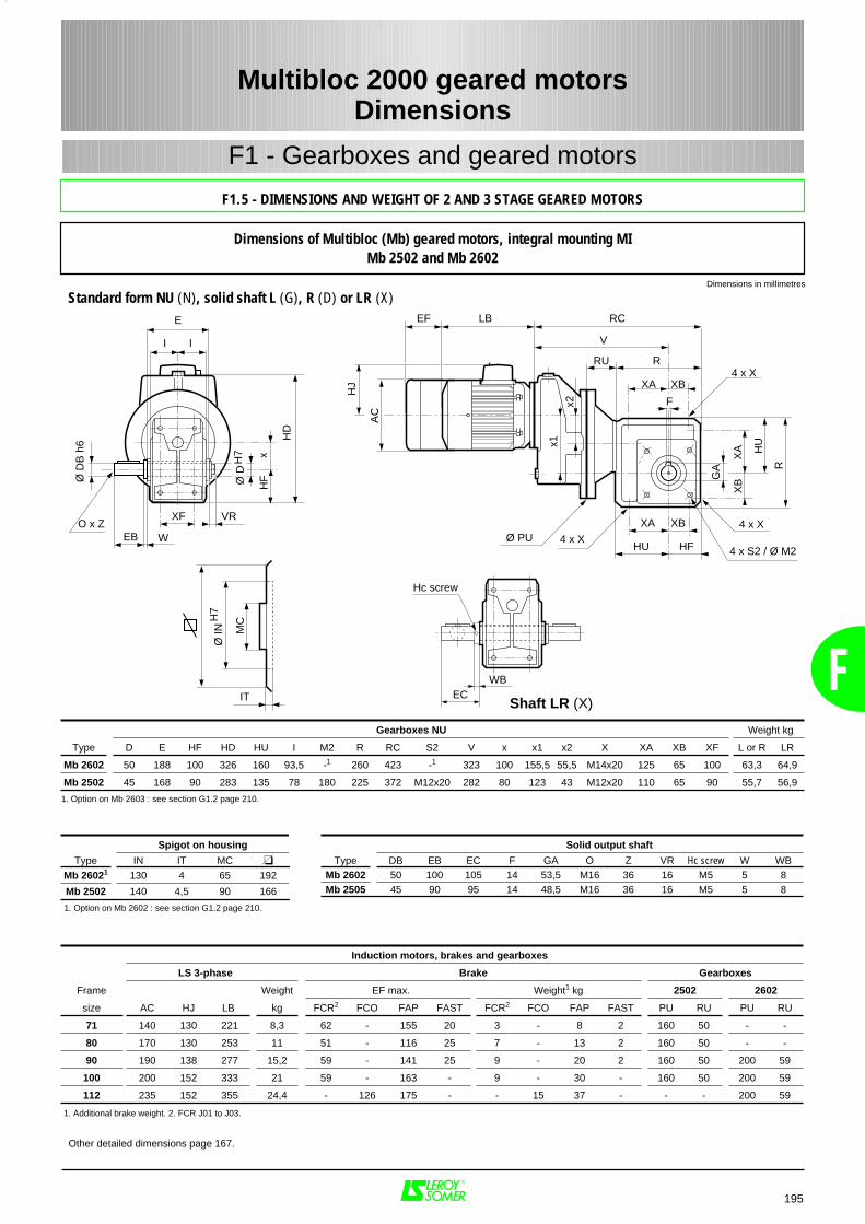
F
RC
V
XB4 x X
F
4 x X4 x X
R
XA
XBG
A
XA XB
XA
Ø PU
I I
E
xH
F
XF
LBEF
AC
HJ
HD
x1
HU
HU
RU R
x2
HFEB W
Ø D
B h
6
O x ZVR
IT
Ø IN
H7
MC
WBEC
Ø D
H7
Hc screw
4 x S2 / Ø M2
Spigot on housing
Type IN IT MC
Mb 26021 130 4 65 192
Mb 2502 140 4,5 90 166
1. Option on Mb 2602 : see section G1.2 page 210.
Gearboxes NU Weight kg
Type D E HF HD HU I M2 R RC S2 V x x1 x2 X XA XB XF L or R LR
Mb 2602 50 188 100 326 160 93,5 -1 260 423 -1 323 100 155,5 55,5 M14x20 125 65 100 63,3 64,9
Mb 2502 45 168 90 283 135 78 180 225 372 M12x20 282 80 123 43 M12x20 110 65 90 55,7 56,9
1. Option on Mb 2603 : see section G1.2 page 210.
Induction motors, brakes and gearboxes
LS 3-phase Brake Gearboxes
Frame Weight EF max. Weight1 kg 2502 2602
size AC HJ LB kg FCR2 FCO FAP FAST FCR2 FCO FAP FAST PU RU PU RU
71 140 130 221 8,3 62 - 155 20 3 - 8 2 160 50 - -
80 170 130 253 11 51 - 116 25 7 - 13 2 160 50 - -
90 190 138 277 15,2 59 - 141 25 9 - 20 2 160 50 200 59
100 200 152 333 21 59 - 163 - 9 - 30 - 160 50 200 59
112 235 152 355 24,4 - 126 175 - - 15 37 - - - 200 59
1. Additional brake weight. 2. FCR J01 to J03.
Solid output shaft
Type DB EB EC F GA O Z VR Hc screw W WBMb 2602 50 100 105 14 53,5 M16 36 16 M5 5 8Mb 2505 45 90 95 14 48,5 M16 36 16 M5 5 8
Other detailed dimensions page 167.
Multibloc 2000 geared motorsDimensions
195
F1 - Gearboxes and geared motors
Dimensions of Multibloc (Mb) geared motors, integral mounting MIMb 2502 and Mb 2602
Dimensions in millimetres
F1.5 - DIMENSIONS AND WEIGHT OF 2 AND 3 STAGE GEARED MOTORS
Standard form NU (N), solid shaft L (G), R (D) or LR (X)
Shaft LR (X)
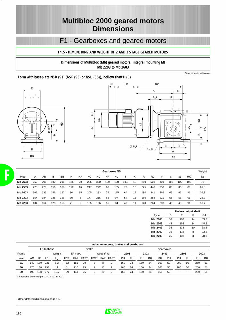
Induction motors, brakes and gearboxes
LS 3-phase Brake Gearboxes
Frame Weight EF max. Weight1 kg 2203 2303 2403 2503 2603
size AC HJ LB kg FCR2 FAP FAST FCR2 FAP FAST PU RU PU RU PU RU PU RU PU RU
71 140 130 221 8,3 62 155 20 3 8 2 160 24 160 24 160 50 200 50 250 51
80 170 130 253 11 51 116 25 7 13 2 160 24 160 24 160 50 200 50 250 51
90 190 138 277 15,2 59 141 25 9 20 2 160 24 160 24 160 50 - - 250 51
1. Additional brake weight. 2. FCR J01 to J03.
Gearboxes NS Weight
Type A AB B BB H HA HC HD HF HU I K R RC V x x1 HK kg
Mb 2603 250 296 180 216 125 20 285 350 100 160 93,5 18 260 503 403 100 100 100 73
Mb 2503 220 270 156 188 112 16 247 292 90 135 78 16 225 440 350 80 80 80 61,5
Mb 2403 202 235 156 187 90 15 205 233 75 115 64 14 190 341 266 63 63 91 36,2
Mb 2303 154 184 128 156 80 6 177 215 63 97 54 11 160 284 221 55 55 91 23,2
Mb 2203 134 164 125 153 71 6 155 196 56 84 49 11 140 264 208 45 45 91 18,7
Hollow output shaft
Type D E F GA
Mb 2603 50 188 14 53,8
Mb 2503 45 168 14 48,8
Mb 2403 35 138 10 38,3
Mb 2303 30 118 8 33,3
Mb 2203 25 108 8 28,3
Multibloc 2000 geared motorsDimensions
196
F
F1 - Gearboxes and geared motors
Dimensions of Multibloc (Mb) geared motors, integral mounting MIMb 2203 to Mb 2603
Other detailed dimensions page 167.
Dimensions in millimetres
V
F
4 x K
HC
GA
==
A
AB
HU
HA
I I
E
B
BB
xH
RC
Ø PU
LBEF
AC
HJ
HD
x1
RRU
HFH
K
Ø D
H7
F1.5 - DIMENSIONS AND WEIGHT OF 2 AND 3 STAGE GEARED MOTORS
Form with baseplate NSD (S1) (NSF (S3) or NSU (S5)), hollow shaft H (C)
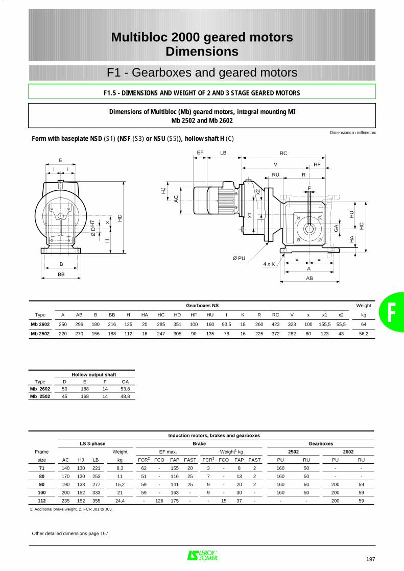
F
V
F
4 x K
HC
GA
==
A
AB
HU
HA
RC
Ø PU
LBEF
RRU
HF
AC
HJ
x1
x2
I I
E
B
BB
xH
HD
Ø D
H7
Induction motors, brakes and gearboxes
LS 3-phase Brake Gearboxes
Frame Weight EF max. Weight1 kg 2502 2602
size AC HJ LB kg FCR2 FCO FAP FAST FCR2 FCO FAP FAST PU RU PU RU
71 140 130 221 8,3 62 - 155 20 3 - 8 2 160 50 - -
80 170 130 253 11 51 - 116 25 7 - 13 2 160 50 - -
90 190 138 277 15,2 59 - 141 25 9 - 20 2 160 50 200 59
100 200 152 333 21 59 - 163 - 9 - 30 - 160 50 200 59
112 235 152 355 24,4 - 126 175 - - 15 37 - - - 200 59
1. Additional brake weight. 2. FCR J01 to J03.
Gearboxes NS Weight
Type A AB B BB H HA HC HD HF HU I K R RC V x x1 x2 kg
Mb 2602 250 296 180 216 125 20 285 351 100 160 93,5 18 260 423 323 100 155,5 55,5 64
Mb 2502 220 270 156 188 112 16 247 305 90 135 78 16 225 372 282 80 123 43 56,2
Hollow output shaft
Type D E F GA
Mb 2602 50 188 14 53,8
Mb 2502 45 168 14 48,8
197
Multibloc 2000 geared motorsDimensions
F1 - Gearboxes and geared motors
Dimensions of Multibloc (Mb) geared motors, integral mounting MIMb 2502 and Mb 2602
Other detailed dimensions page 167.
Dimensions in millimetres
F1.5 - DIMENSIONS AND WEIGHT OF 2 AND 3 STAGE GEARED MOTORS
Form with baseplate NSD (S1) (NSF (S3) or NSU (S5)), hollow shaft H (C)
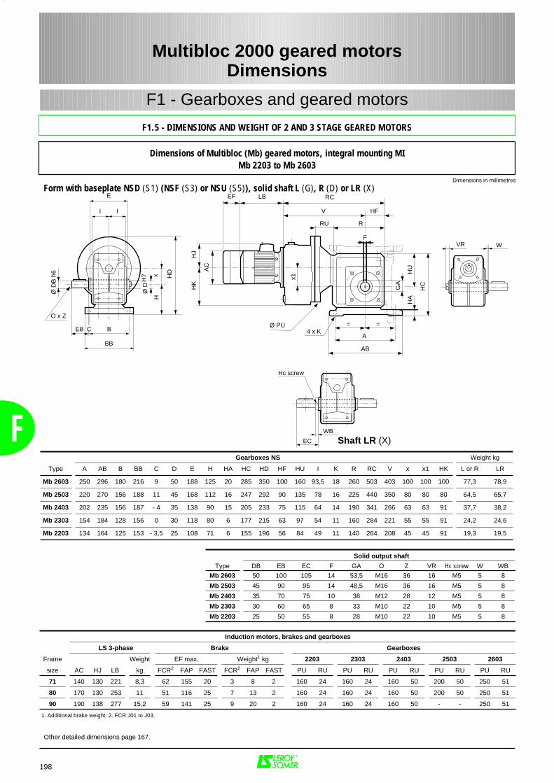
F
V
F
4 x K
HC
GA
==
A
AB
HU
HA
I I
E
B
BB
xH
RC
Ø PU
LBEF
AC
HJ
HD
x1
RRU
HF
HK
EB
Ø D
B h
6
O x Z
WB
Hc screw
EC
VR W
Ø D
H7
C
Solid output shaft
Type DB EB EC F GA O Z VR Hc screw W WB
Mb 2603 50 100 105 14 53,5 M16 36 16 M5 5 8
Mb 2503 45 90 95 14 48,5 M16 36 16 M5 5 8
Mb 2403 35 70 75 10 38 M12 28 12 M5 5 8
Mb 2303 30 60 65 8 33 M10 22 10 M5 5 8
Mb 2203 25 50 55 8 28 M10 22 10 M5 5 8
Gearboxes NS Weight kg
Type A AB B BB C D E H HA HC HD HF HU I K R RC V x x1 HK L or R LR
Mb 2603 250 296 180 216 9 50 188 125 20 285 350 100 160 93,5 18 260 503 403 100 100 100 77,3 78,9
Mb 2503 220 270 156 188 11 45 168 112 16 247 292 90 135 78 16 225 440 350 80 80 80 64,5 65,7
Mb 2403 202 235 156 187 - 4 35 138 90 15 205 233 75 115 64 14 190 341 266 63 63 91 37,7 38,2
Mb 2303 154 184 128 156 0 30 118 80 6 177 215 63 97 54 11 160 284 221 55 55 91 24,2 24,6
Mb 2203 134 164 125 153 - 3,5 25 108 71 6 155 196 56 84 49 11 140 264 208 45 45 91 19,3 19,5
198
Multibloc 2000 geared motorsDimensions
F1 - Gearboxes and geared motors
Dimensions of Multibloc (Mb) geared motors, integral mounting MIMb 2203 to Mb 2603
Other detailed dimensions page 167.
Induction motors, brakes and gearboxes
LS 3-phase Brake Gearboxes
Frame Weight EF max. Weight1 kg 2203 2303 2403 2503 2603
size AC HJ LB kg FCR2 FAP FAST FCR2 FAP FAST PU RU PU RU PU RU PU RU PU RU
71 140 130 221 8,3 62 155 20 3 8 2 160 24 160 24 160 50 200 50 250 51
80 170 130 253 11 51 116 25 7 13 2 160 24 160 24 160 50 200 50 250 51
90 190 138 277 15,2 59 141 25 9 20 2 160 24 160 24 160 50 - - 250 51
1. Additional brake weight. 2. FCR J01 to J03.
Dimensions in millimetres
F1.5 - DIMENSIONS AND WEIGHT OF 2 AND 3 STAGE GEARED MOTORS
Form with baseplate NSD (S1) (NSF (S3) or NSU (S5)), solid shaft L (G), R (D) or LR (X)
Shaft LR (X)
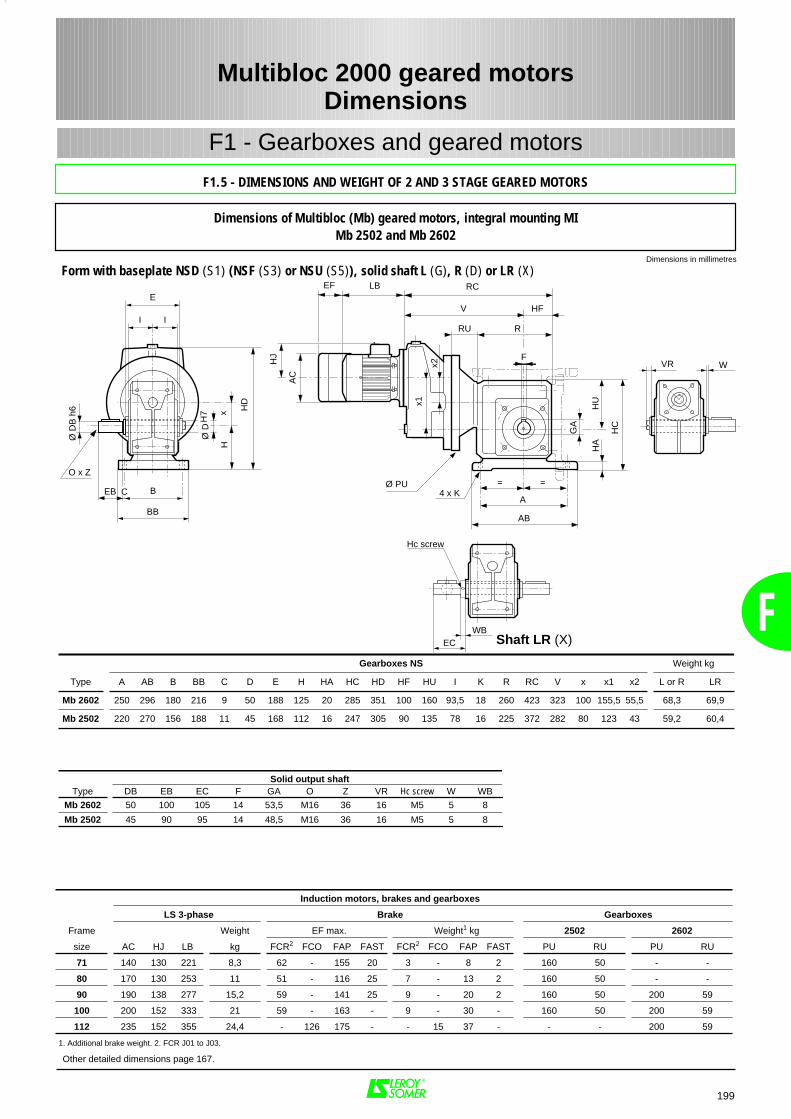
F
V
F
4 x K
HC
GA
==
A
AB
HU
HA
I I
E
B
BB
xH
RC
Ø PU
LBEF
HD
RRU
HF
AC
HJ
x1
x2
EB
Ø D
B h
6
O x Z
WBEC
VR W
Ø D
H7
C
Hc screw
199
Multibloc 2000 geared motorsDimensions
F1 - Gearboxes and geared motors
Dimensions of Multibloc (Mb) geared motors, integral mounting MIMb 2502 and Mb 2602
Gearboxes NS Weight kg
Type A AB B BB C D E H HA HC HD HF HU I K R RC V x x1 x2 L or R LR
Mb 2602 250 296 180 216 9 50 188 125 20 285 351 100 160 93,5 18 260 423 323 100 155,5 55,5 68,3 69,9
Mb 2502 220 270 156 188 11 45 168 112 16 247 305 90 135 78 16 225 372 282 80 123 43 59,2 60,4
Solid output shaftType DB EB EC F GA O Z VR Hc screw W WB
Mb 2602 50 100 105 14 53,5 M16 36 16 M5 5 8
Mb 2502 45 90 95 14 48,5 M16 36 16 M5 5 8
Induction motors, brakes and gearboxes
LS 3-phase Brake Gearboxes
Frame Weight EF max. Weight1 kg 2502 2602
size AC HJ LB kg FCR2 FCO FAP FAST FCR2 FCO FAP FAST PU RU PU RU
71 140 130 221 8,3 62 - 155 20 3 - 8 2 160 50 - -
80 170 130 253 11 51 - 116 25 7 - 13 2 160 50 - -
90 190 138 277 15,2 59 - 141 25 9 - 20 2 160 50 200 59
100 200 152 333 21 59 - 163 - 9 - 30 - 160 50 200 59
112 235 152 355 24,4 - 126 175 - - 15 37 - - - 200 59
1. Additional brake weight. 2. FCR J01 to J03.
Dimensions in millimetres
F1.5 - DIMENSIONS AND WEIGHT OF 2 AND 3 STAGE GEARED MOTORS
Form with baseplate NSD (S1) (NSF (S3) or NSU (S5)), solid shaft L (G), R (D) or LR (X)
Other detailed dimensions page 167.
Shaft LR (X)

F
200
Multibloc 2000 geared motorsDimensions
F1 - Gearboxes and geared motors
Dimensions of Multibloc (Mb) geared motors, integral mounting MIMb 2203 to Mb 2603
Other detailed dimensions page 167.
Dimensions in millimetres
4 x S / Ø M
GA
Ø PUx1
I A I
E
Ø D
H7 x
HF
T LA
P Nj6
HD AC
HJ
R
GA
HU
F
V HF
RCLBEF
RRU
Gearboxes with flange Flange BS or BN Weight
Type HF HD HU I IA R RC V x x1 M N1 P LA S T1 kg
Mb 2603 100 325 160 93,5 153 260 503 403 100 100 300 250 350 14 18 5 74,5
Mb 2503 90 270 135 78 126 225 440 350 80 80 265 230 300 12 14 4 63,5
Mb 2403 75 218 115 64 126 190 341 266 63 63 215 180 250 12 14 4 39,2
Mb 2303 63 198 97 54 106 160 284 221 55 55 165 130 200 10 11 3,5 25,2
Mb 2203 56 181 84 49 100,5 140 264 208 45 45 165 130 200 10 11 3,5 20,7
1. Flange without spigot BN : N j6 = 0 and T = 0.
Hollow output shaft
Type D E F GA
Mb 2603 50 188 14 53,8
Mb 2503 45 168 14 48,8
Mb 2403 35 138 10 38,3
Mb 2303 30 118 8 33,3
Mb 2203 25 108 8 28,3
Induction motors, brakes and gearboxes
LS 3-phase Brake Gearboxes
Frame Weight EF max. Weight1 kg 2203 2303 2403 2503 2603
size AC HJ LB kg FCR2 FAP FAST FCR2 FAP FAST PU RU PU RU PU RU PU RU PU RU
71 140 130 221 8,3 62 155 20 3 8 2 160 24 160 24 160 50 200 50 250 51
80 170 130 253 11 51 116 25 7 13 2 160 24 160 24 160 50 200 50 250 51
90 190 138 277 15,2 59 141 25 9 20 2 160 24 160 24 160 50 - - 250 51
1. Additional brake weight. 2. FCR J01 to J03.
F1.5 - DIMENSIONS AND WEIGHT OF 2 AND 3 STAGE GEARED MOTORS
Form with standard flange BS (or flange without spigot BN), hollow shaft H (C)
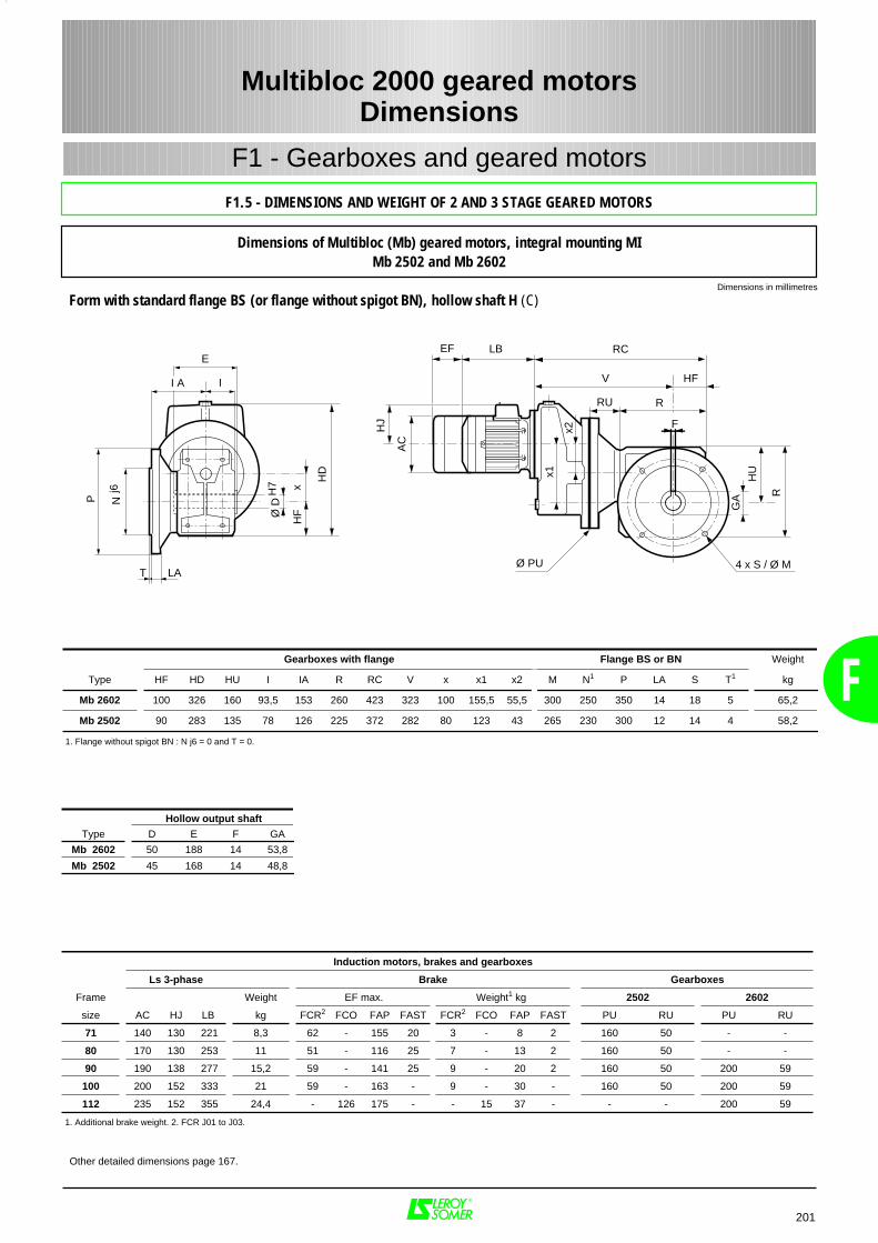
F
Induction motors, brakes and gearboxes
Ls 3-phase Brake Gearboxes
Frame Weight EF max. Weight1 kg 2502 2602
size AC HJ LB kg FCR2 FCO FAP FAST FCR2 FCO FAP FAST PU RU PU RU
71 140 130 221 8,3 62 - 155 20 3 - 8 2 160 50 - -
80 170 130 253 11 51 - 116 25 7 - 13 2 160 50 - -
90 190 138 277 15,2 59 - 141 25 9 - 20 2 160 50 200 59
100 200 152 333 21 59 - 163 - 9 - 30 - 160 50 200 59
112 235 152 355 24,4 - 126 175 - - 15 37 - - - 200 59
1. Additional brake weight. 2. FCR J01 to J03.
Gearboxes with flange Flange BS or BN Weight
Type HF HD HU I IA R RC V x x1 x2 M N1 P LA S T1 kg
Mb 2602 100 326 160 93,5 153 260 423 323 100 155,5 55,5 300 250 350 14 18 5 65,2
Mb 2502 90 283 135 78 126 225 372 282 80 123 43 265 230 300 12 14 4 58,2
1. Flange without spigot BN : N j6 = 0 and T = 0.
Hollow output shaft
Type D E F GA
Mb 2602 50 188 14 53,8
Mb 2502 45 168 14 48,8
201
Multibloc 2000 geared motorsDimensions
F1 - Gearboxes and geared motors
Dimensions of Multibloc (Mb) geared motors, integral mounting MIMb 2502 and Mb 2602
Other detailed dimensions page 167.
Dimensions in millimetres
4 x S / Ø M
R
GA
F
V HF
HU
I A I
E
Ø D
H7 x
HF
T LA
P Nj6
RC
Ø PU
LBEF
AC
HJ
HD x1
RRU
x2
F1.5 - DIMENSIONS AND WEIGHT OF 2 AND 3 STAGE GEARED MOTORS
Form with standard flange BS (or flange without spigot BN), hollow shaft H (C)
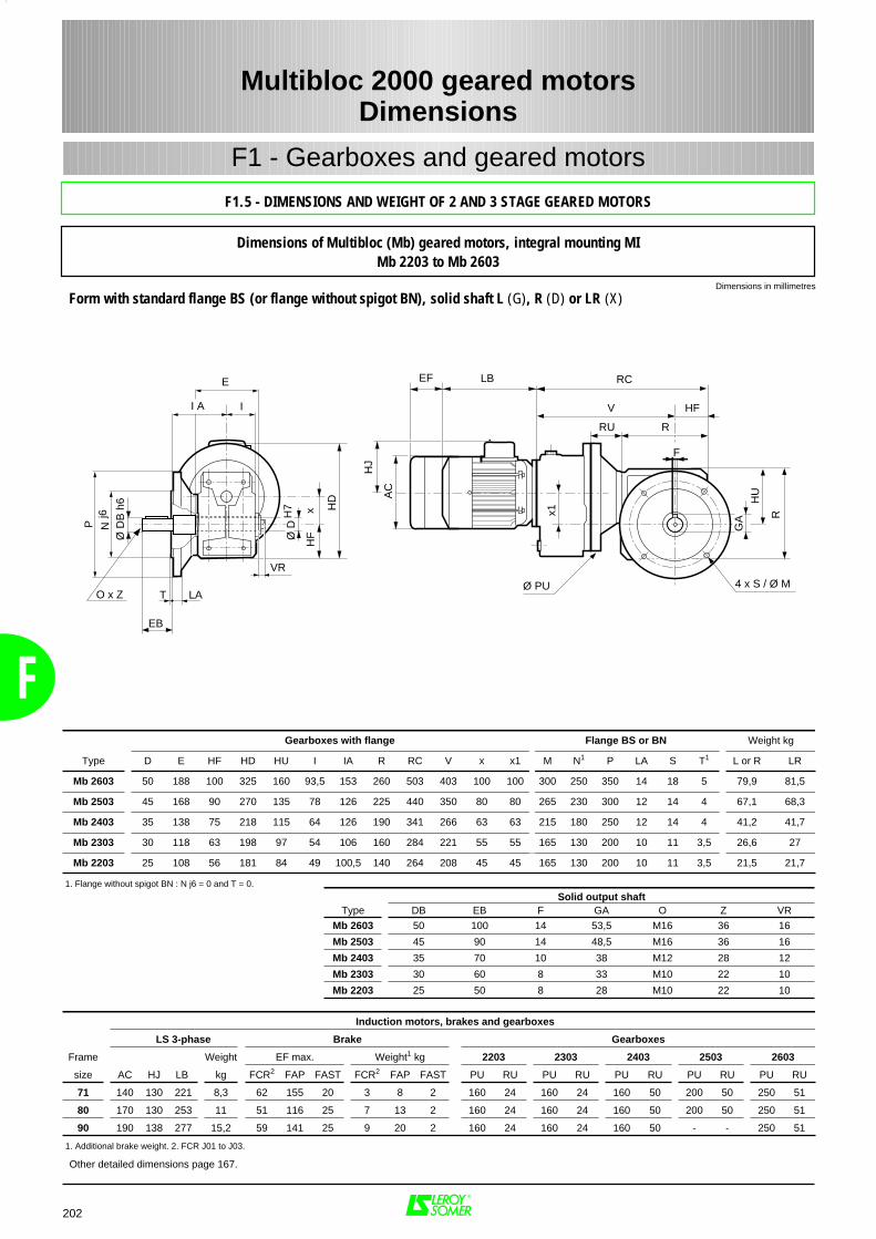
F Gearboxes with flange Flange BS or BN Weight kg
Type D E HF HD HU I IA R RC V x x1 M N1 P LA S T1 L or R LR
Mb 2603 50 188 100 325 160 93,5 153 260 503 403 100 100 300 250 350 14 18 5 79,9 81,5
Mb 2503 45 168 90 270 135 78 126 225 440 350 80 80 265 230 300 12 14 4 67,1 68,3
Mb 2403 35 138 75 218 115 64 126 190 341 266 63 63 215 180 250 12 14 4 41,2 41,7
Mb 2303 30 118 63 198 97 54 106 160 284 221 55 55 165 130 200 10 11 3,5 26,6 27
Mb 2203 25 108 56 181 84 49 100,5 140 264 208 45 45 165 130 200 10 11 3,5 21,5 21,7
1. Flange without spigot BN : N j6 = 0 and T = 0.
202
Multibloc 2000 geared motorsDimensions
F1 - Gearboxes and geared motors
Dimensions of Multibloc (Mb) geared motors, integral mounting MIMb 2203 to Mb 2603
Other detailed dimensions page 167.
Induction motors, brakes and gearboxes
LS 3-phase Brake Gearboxes
Frame Weight EF max. Weight1 kg 2203 2303 2403 2503 2603
size AC HJ LB kg FCR2 FAP FAST FCR2 FAP FAST PU RU PU RU PU RU PU RU PU RU
71 140 130 221 8,3 62 155 20 3 8 2 160 24 160 24 160 50 200 50 250 51
80 170 130 253 11 51 116 25 7 13 2 160 24 160 24 160 50 200 50 250 51
90 190 138 277 15,2 59 141 25 9 20 2 160 24 160 24 160 50 - - 250 51
1. Additional brake weight. 2. FCR J01 to J03.
Dimensions in millimetres
I A I
E
Ø D
H7 x
HF
T LA
P Nj6
HD
EB
Ø D
B h
6
O x Z
VR
4 x S / Ø M
R
GA
F
V HF
HU
RC
Ø PU
LBEFA
C
HJ
x1
RRU
F1.5 - DIMENSIONS AND WEIGHT OF 2 AND 3 STAGE GEARED MOTORS
Form with standard flange BS (or flange without spigot BN), solid shaft L (G), R (D) or LR (X)
Solid output shaftType DB EB F GA O Z VR
Mb 2603 50 100 14 53,5 M16 36 16
Mb 2503 45 90 14 48,5 M16 36 16
Mb 2403 35 70 10 38 M12 28 12
Mb 2303 30 60 8 33 M10 22 10
Mb 2203 25 50 8 28 M10 22 10
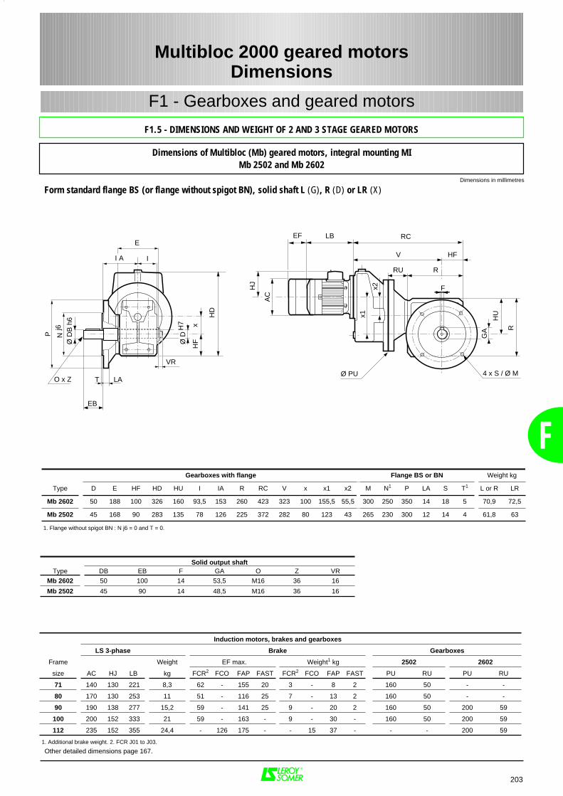
F
203
Multibloc 2000 geared motorsDimensions
F1 - Gearboxes and geared motors
Dimensions of Multibloc (Mb) geared motors, integral mounting MIMb 2502 and Mb 2602
Other detailed dimensions page 167.
Gearboxes with flange Flange BS or BN Weight kg
Type D E HF HD HU I IA R RC V x x1 x2 M N1 P LA S T1 L or R LR
Mb 2602 50 188 100 326 160 93,5 153 260 423 323 100 155,5 55,5 300 250 350 14 18 5 70,9 72,5
Mb 2502 45 168 90 283 135 78 126 225 372 282 80 123 43 265 230 300 12 14 4 61,8 63
1. Flange without spigot BN : N j6 = 0 and T = 0.
Solid output shaftType DB EB F GA O Z VR
Mb 2602 50 100 14 53,5 M16 36 16
Mb 2502 45 90 14 48,5 M16 36 16
Induction motors, brakes and gearboxes
LS 3-phase Brake Gearboxes
Frame Weight EF max. Weight1 kg 2502 2602
size AC HJ LB kg FCR2 FCO FAP FAST FCR2 FCO FAP FAST PU RU PU RU
71 140 130 221 8,3 62 - 155 20 3 - 8 2 160 50 - -
80 170 130 253 11 51 - 116 25 7 - 13 2 160 50 - -
90 190 138 277 15,2 59 - 141 25 9 - 20 2 160 50 200 59
100 200 152 333 21 59 - 163 - 9 - 30 - 160 50 200 59
112 235 152 355 24,4 - 126 175 - - 15 37 - - - 200 59
1. Additional brake weight. 2. FCR J01 to J03.
Dimensions in millimetres
4 x S / Ø M
R
GA
F
V HF
HU
I A I
E
Ø D
H7 x
HF
T LA
P Nj6
RC
Ø PU
LBEF
AC
HJ
HD
x1
RRU
x2
EB
Ø D
B h
6
O x Z
VR
F1.5 - DIMENSIONS AND WEIGHT OF 2 AND 3 STAGE GEARED MOTORS
Form standard flange BS (or flange without spigot BN), solid shaft L (G), R (D) or LR (X)
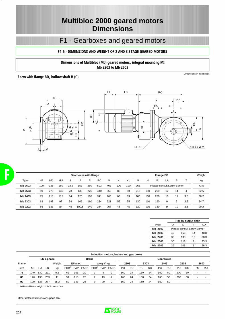
F
204
Multibloc 2000 geared motorsDimensions
F1 - Gearboxes and geared motors
Dimensions of Multibloc (Mb) geared motors, integral mounting MIMb 2203 to Mb 2603
Other detailed dimensions page 167.
Dimensions in millimetres
4 x S / Ø M
GA
Ø PU
x1
I A I
E
Ø D
H7 x
HF
T LA
P Nj6
HD AC
HJ
R
GA
HU
F
V HF
RCLBEF
RRU
Gearboxes with flange Flange BD Weight
Type HF HD HU I IA R RC V x x1 M N P LA S T kg
Mb 2603 100 325 160 93,5 153 260 503 403 100 100 265 Please consult Leroy-Somer 73,5
Mb 2503 90 270 135 78 138 225 440 350 80 80 215 180 250 12 14 4 62,5
Mb 2403 75 218 115 64 126 190 341 266 63 63 165 130 200 10 11 3,5 38,2
Mb 2303 63 198 97 54 106 160 284 221 55 55 130 110 160 9 9 3,5 24,7
Mb 2203 56 181 84 49 100,5 140 264 208 45 45 130 110 160 9 10 3,5 20,2
Hollow output shaft
Type D E F GA
Mb 2603 Please consult Leroy-Somer
Mb 2503 45 168 14 48,8
Mb 2403 35 138 10 38,3
Mb 2303 30 118 8 33,3
Mb 2203 25 108 8 28,3
Induction motors, brakes and gearboxes
LS 3-phase Brake Gearboxes
Frame Weight EF max. Weight1 kg 2203 2303 2403 2503 2603
size AC HJ LB kg FCR2 FAP FAST FCR2 FAP FAST PU RU PU RU PU RU PU RU PU RU
71 140 130 221 8,3 62 155 20 3 8 2 160 24 160 24 160 50 200 50 - -
80 170 130 253 11 51 116 25 7 13 2 160 24 160 24 160 50 200 50 - -
90 190 138 277 15,2 59 141 25 9 20 2 160 24 160 24 160 50 - - - -
1. Additional brake weight. 2. FCR J01 to J03.
F1.5 - DIMENSIONS AND WEIGHT OF 2 AND 3 STAGE GEARED MOTORS
Form with flange BD, hollow shaft H (C)
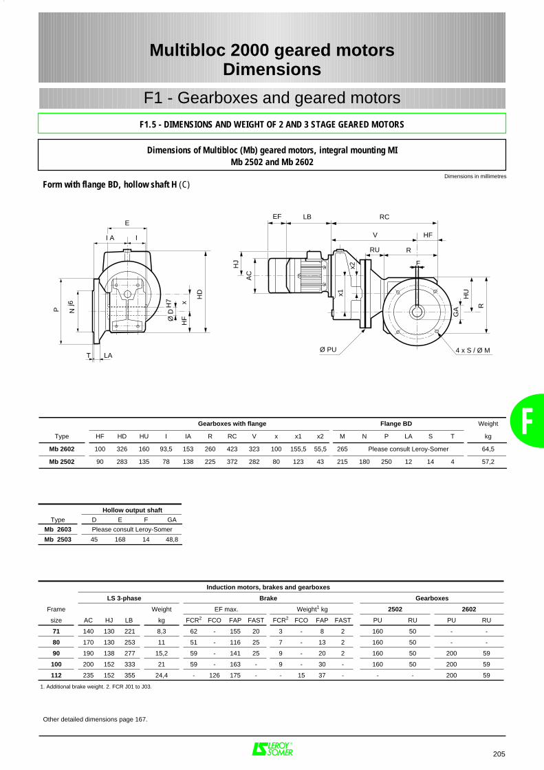
F
Induction motors, brakes and gearboxes
LS 3-phase Brake Gearboxes
Frame Weight EF max. Weight1 kg 2502 2602
size AC HJ LB kg FCR2 FCO FAP FAST FCR2 FCO FAP FAST PU RU PU RU
71 140 130 221 8,3 62 - 155 20 3 - 8 2 160 50 - -
80 170 130 253 11 51 - 116 25 7 - 13 2 160 50 - -
90 190 138 277 15,2 59 - 141 25 9 - 20 2 160 50 200 59
100 200 152 333 21 59 - 163 - 9 - 30 - 160 50 200 59
112 235 152 355 24,4 - 126 175 - - 15 37 - - - 200 59
1. Additional brake weight. 2. FCR J01 to J03.
Gearboxes with flange Flange BD Weight
Type HF HD HU I IA R RC V x x1 x2 M N P LA S T kg
Mb 2602 100 326 160 93,5 153 260 423 323 100 155,5 55,5 265 Please consult Leroy-Somer 64,5
Mb 2502 90 283 135 78 138 225 372 282 80 123 43 215 180 250 12 14 4 57,2
Hollow output shaft
Type D E F GA
Mb 2603 Please consult Leroy-Somer
Mb 2503 45 168 14 48,8
205
Multibloc 2000 geared motorsDimensions
F1 - Gearboxes and geared motors
Dimensions of Multibloc (Mb) geared motors, integral mounting MIMb 2502 and Mb 2602
Other detailed dimensions page 167.
Dimensions in millimetres
4 x S / Ø M
R
GA
F
V HF
HU
I A I
E
Ø D
H7 x
HF
T LA
P Nj6
RC
Ø PU
LBEF
AC
HJ
HD x1
RRU
x2
F1.5 - DIMENSIONS AND WEIGHT OF 2 AND 3 STAGE GEARED MOTORS
Form with flange BD, hollow shaft H (C)
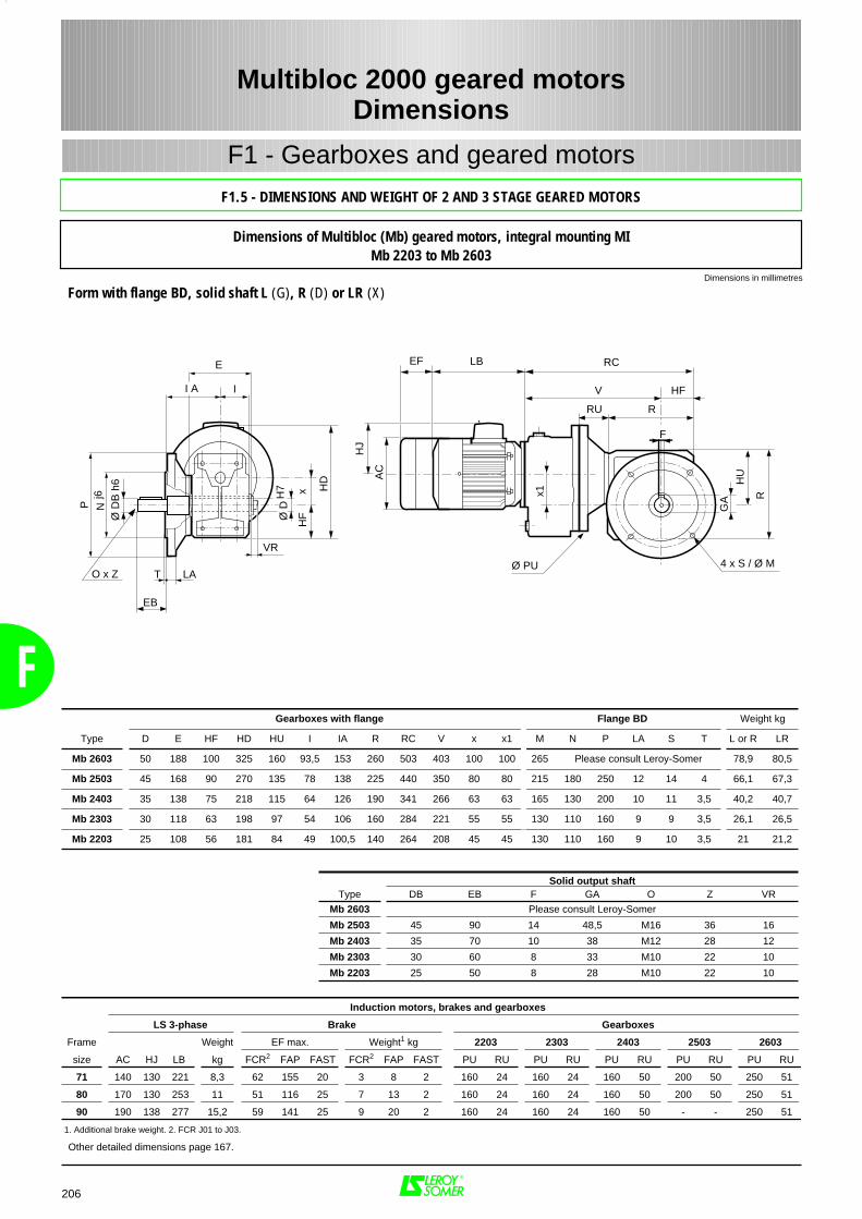
F
Solid output shaftType DB EB F GA O Z VR
Mb 2603 Please consult Leroy-Somer
Mb 2503 45 90 14 48,5 M16 36 16
Mb 2403 35 70 10 38 M12 28 12
Mb 2303 30 60 8 33 M10 22 10
Mb 2203 25 50 8 28 M10 22 10
Gearboxes with flange Flange BD Weight kg
Type D E HF HD HU I IA R RC V x x1 M N P LA S T L or R LR
Mb 2603 50 188 100 325 160 93,5 153 260 503 403 100 100 265 Please consult Leroy-Somer 78,9 80,5
Mb 2503 45 168 90 270 135 78 138 225 440 350 80 80 215 180 250 12 14 4 66,1 67,3
Mb 2403 35 138 75 218 115 64 126 190 341 266 63 63 165 130 200 10 11 3,5 40,2 40,7
Mb 2303 30 118 63 198 97 54 106 160 284 221 55 55 130 110 160 9 9 3,5 26,1 26,5
Mb 2203 25 108 56 181 84 49 100,5 140 264 208 45 45 130 110 160 9 10 3,5 21 21,2
206
Multibloc 2000 geared motorsDimensions
F1 - Gearboxes and geared motors
Dimensions of Multibloc (Mb) geared motors, integral mounting MIMb 2203 to Mb 2603
Other detailed dimensions page 167.
Induction motors, brakes and gearboxes
LS 3-phase Brake Gearboxes
Frame Weight EF max. Weight1 kg 2203 2303 2403 2503 2603
size AC HJ LB kg FCR2 FAP FAST FCR2 FAP FAST PU RU PU RU PU RU PU RU PU RU
71 140 130 221 8,3 62 155 20 3 8 2 160 24 160 24 160 50 200 50 250 51
80 170 130 253 11 51 116 25 7 13 2 160 24 160 24 160 50 200 50 250 51
90 190 138 277 15,2 59 141 25 9 20 2 160 24 160 24 160 50 - - 250 51
1. Additional brake weight. 2. FCR J01 to J03.
Dimensions in millimetres
I A I
E
Ø D
H7 x
HF
T LA
P Nj6
HD
EB
Ø D
B h
6
O x Z
VR
4 x S / Ø M
R
GA
F
V HF
HU
RC
Ø PU
LBEF
AC
HJ
x1
RRU
F1.5 - DIMENSIONS AND WEIGHT OF 2 AND 3 STAGE GEARED MOTORS
Form with flange BD, solid shaft L (G), R (D) or LR (X)
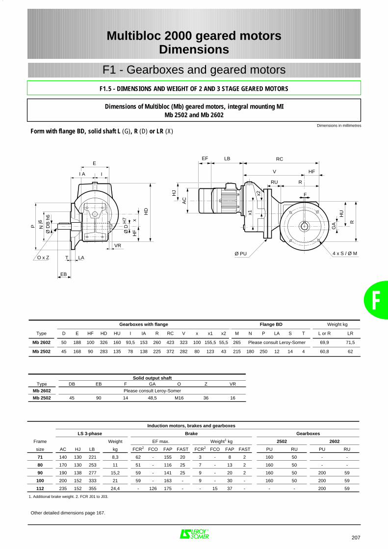
F
207
Multibloc 2000 geared motorsDimensions
F1 - Gearboxes and geared motors
Dimensions of Multibloc (Mb) geared motors, integral mounting MIMb 2502 and Mb 2602
Other detailed dimensions page 167.
Gearboxes with flange Flange BD Weight kg
Type D E HF HD HU I IA R RC V x x1 x2 M N P LA S T L or R LR
Mb 2602 50 188 100 326 160 93,5 153 260 423 323 100 155,5 55,5 265 Please consult Leroy-Somer 69,9 71,5
Mb 2502 45 168 90 283 135 78 138 225 372 282 80 123 43 215 180 250 12 14 4 60,8 62
Induction motors, brakes and gearboxes
LS 3-phase Brake Gearboxes
Frame Weight EF max. Weight1 kg 2502 2602
size AC HJ LB kg FCR2 FCO FAP FAST FCR2 FCO FAP FAST PU RU PU RU
71 140 130 221 8,3 62 - 155 20 3 - 8 2 160 50 - -
80 170 130 253 11 51 - 116 25 7 - 13 2 160 50 - -
90 190 138 277 15,2 59 - 141 25 9 - 20 2 160 50 200 59
100 200 152 333 21 59 - 163 - 9 - 30 - 160 50 200 59
112 235 152 355 24,4 - 126 175 - - 15 37 - - - 200 59
1. Additional brake weight. 2. FCR J01 to J03.
Dimensions in millimetres
4 x S / Ø M
R
GA
F
V HF
HU
I A I
E
Ø D
H7 x
HF
T LA
P Nj6
RC
Ø PU
LBEF
AC
HJ
HD
x1
RRU
x2
EB
Ø D
B h
6
O x Z
VR
F1.5 - DIMENSIONS AND WEIGHT OF 2 AND 3 STAGE GEARED MOTORS
Form with flange BD, solid shaft L (G), R (D) or LR (X)
Solid output shaftType DB EB F GA O Z VR
Mb 2602 Please consult Leroy-Somer
Mb 2502 45 90 14 48,5 M16 36 16
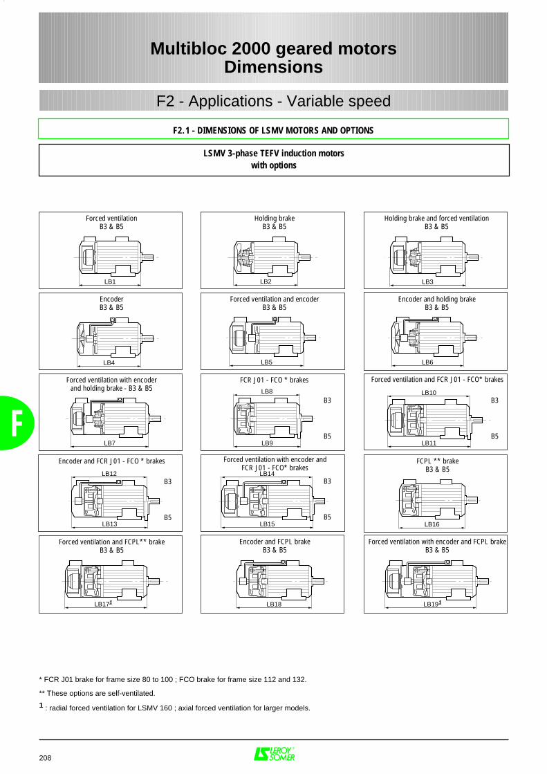
F
208
Multibloc 2000 geared motorsDimensions
F2.1 - DIMENSIONS OF LSMV MOTORS AND OPTIONS
F2 - Applications - Variable speed
LB2LB1 LB3
LB4 LB5
LB7
LB6
LB11
LB10
LB17
LB13
LB12
LB15
LB14
LB18 LB19
LB9
LB8
LB16
1 1
Forced ventilationB3 & B5
Holding brakeB3 & B5
Holding brake and forced ventilationB3 & B5
EncoderB3 & B5
Forced ventilation and encoderB3 & B5
Encoder and holding brakeB3 & B5
Forced ventilation with encoderand holding brake - B3 & B5
FCR J01 - FCO * brakes
Forced ventilation and FCPL** brakeB3 & B5
FCPL ** brakeB3 & B5
Forced ventilation and FCR J01 - FCO* brakes
Encoder and FCR J01 - FCO * brakes Forced ventilation with encoder andFCR J01 - FCO* brakes
Encoder and FCPL brakeB3 & B5
Forced ventilation with encoder and FCPL brakeB3 & B5
B3
B5
B3
B5
B3
B5
B3
B5
LSMV 3-phase TEFV induction motorswith options
* FCR J01 brake for frame size 80 to 100 ; FCO brake for frame size 112 and 132.
** These options are self-ventilated.
1 : radial forced ventilation for LSMV 160 ; axial forced ventilation for larger models.
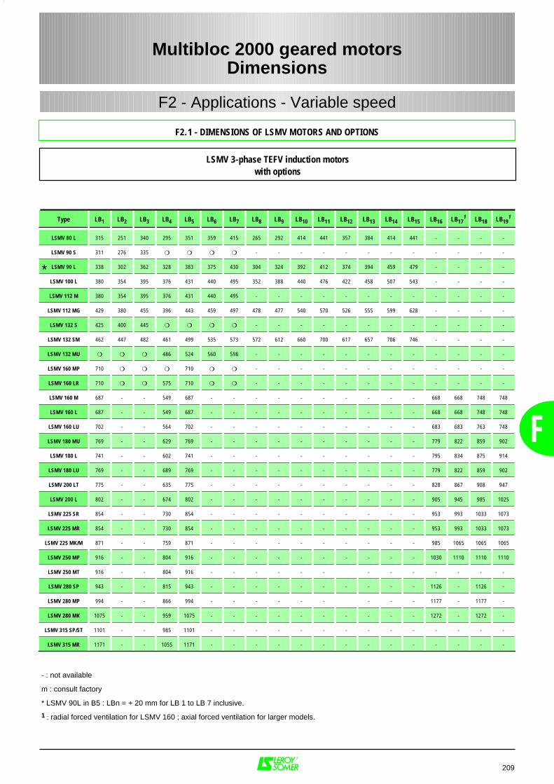
F
209
Multibloc 2000 geared motorsDimensions
F2.1 - DIMENSIONS OF LSMV MOTORS AND OPTIONS
F2 - Applications - Variable speed
Type LB1 LB2 LB3 LB4 LB5 LB6 LB7 LB8 LB9 LB10 LB11 LB12 LB13 LB14 LB15 LB16 LB171 LB18 LB19
1
LSMV 80 L 315 251 340 295 351 359 415 265 292 414 441 357 384 414 441 - - - -
LSMV 90 S 311 276 335 - - - - - - - - - - - -
LSMV 90 L 338 302 362 328 383 375 430 304 324 392 412 374 394 459 479 - - - -
LSMV 100 L 380 354 395 376 431 440 495 352 388 440 476 422 458 507 543 - - - -
LSMV 112 M 380 354 395 376 431 440 495 - - - - - - - - - - - -
LSMV 112 MG 429 380 455 396 443 459 497 478 477 540 570 526 555 599 628 - - - -
LSMV 132 S 425 400 445 - - - - - - - - - - - -
LSMV 132 SM 462 447 482 461 499 535 573 572 612 660 700 617 657 706 746 - - - -
LSMV 132 MU 486 524 560 598 - - - - - - - - - - - -
LSMV 160 MP 710 710 - - - - - - - - - - - -
LSMV 160 LR 710 575 710 - - - - - - - - - - - -
LSMV 160 M 687 - - 549 687 - - - - - - - - - - 668 668 748 748
LSMV 160 L 687 - - 549 687 - - - - - - - - - - 668 668 748 748
LSMV 160 LU 702 - - 564 702 - - - - - - - - - - 683 683 763 748
LSMV 180 MU 769 - - 629 769 - - - - - - - - - - 779 822 859 902
LSMV 180 L 741 - - 602 741 - - - - - - - - - - 795 834 875 914
LSMV 180 LU 769 - - 689 769 - - - - - - - - - - 779 822 859 902
LSMV 200 LT 775 - - 635 775 - - - - - - - - - - 828 867 908 947
LSMV 200 L 802 - - 674 802 - - - - - - - - - - 905 945 985 1025
LSMV 225 SR 854 - - 730 854 - - - - - - - - - - 953 993 1033 1073
LSMV 225 MR 854 - - 730 854 - - - - - - - - - - 953 993 1033 1073
LSMV 225 MK/M 871 - - 759 871 - - - - - - - - - - 985 1065 1065 1065
LSMV 250 MP 916 - - 804 916 - - - - - - - - - - 1030 1110 1110 1110
LSMV 250 MT 916 - - 804 916 - - - - - - - - - - - - -
LSMV 280 SP 943 - - 815 943 - - - - - - - - - - 1126 - 1126 -
LSMV 280 MP 994 - - 866 994 - - - - - - - - - 1177 - 1177 -
LSMV 280 MK 1075 - - 959 1075 - - - - - - - - - - 1272 - 1272 -
LSMV 315 SP/ST 1101 - - 985 1101 - - - - - - - - - - - - - -
LSMV 315 MR 1171 - - 1055 1171 - - - - - - - - - - - - - -
- : not available
m : consult factory
* LSMV 90L in B5 : LBn = + 20 mm for LB 1 to LB 7 inclusive.
1 : radial forced ventilation for LSMV 160 ; axial forced ventilation for larger models.
*
LSMV 3-phase TEFV induction motorswith options
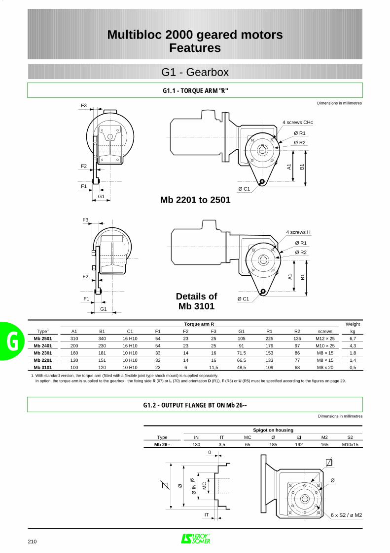
G
210
Multibloc 2000 geared motorsFeatures
G1.1 - TORQUE ARM "R"
G1 - Gearbox
Dimensions in millimetres
A1
Ø C1F1
F3
G1
4 screws H
B1F2
Ø R1
Ø R2
Details ofMb 3101
A1
Ø C1F1
F3
F2
G1
4 screws CHc
Ø R1
B1
Ø R2
Mb 2201 to 2501
Torque arm R Weight
Type1 A1 B1 C1 F1 F2 F3 G1 R1 R2 screws kg
Mb 2501 310 340 16 H10 54 23 25 105 225 135 M12 × 25 6,7
Mb 2401 200 230 16 H10 54 23 25 91 179 97 M10 × 25 4,3
Mb 2301 160 181 10 H10 33 14 16 71,5 153 86 M8 × 15 1,8
Mb 2201 130 151 10 H10 33 14 16 66,5 133 77 M8 × 15 1,4
Mb 3101 100 120 10 H10 23 6 11,5 48,5 109 68 M8 x 20 0,5
G1.2 - OUTPUT FLANGE BT ON Mb 26--
Spigot on housing
Type IN IT MC Ø M2 S2
Mb 26-- 130 3,5 65 185 192 165 M10x15
Dimensions in millimetres
IT
0
Ø IN
Ø
j6
MC
6 x S2 / ø M2
Ø
1. With standard version, the torque arm (fitted with a flexible joint type shock mount) is supplied separately. In option, the torque arm is supplied to the gearbox : the fixing side R (07) or L (70) and orientation D (R1), F (R3) or U (R5) must be specified according to the figures on page 29.
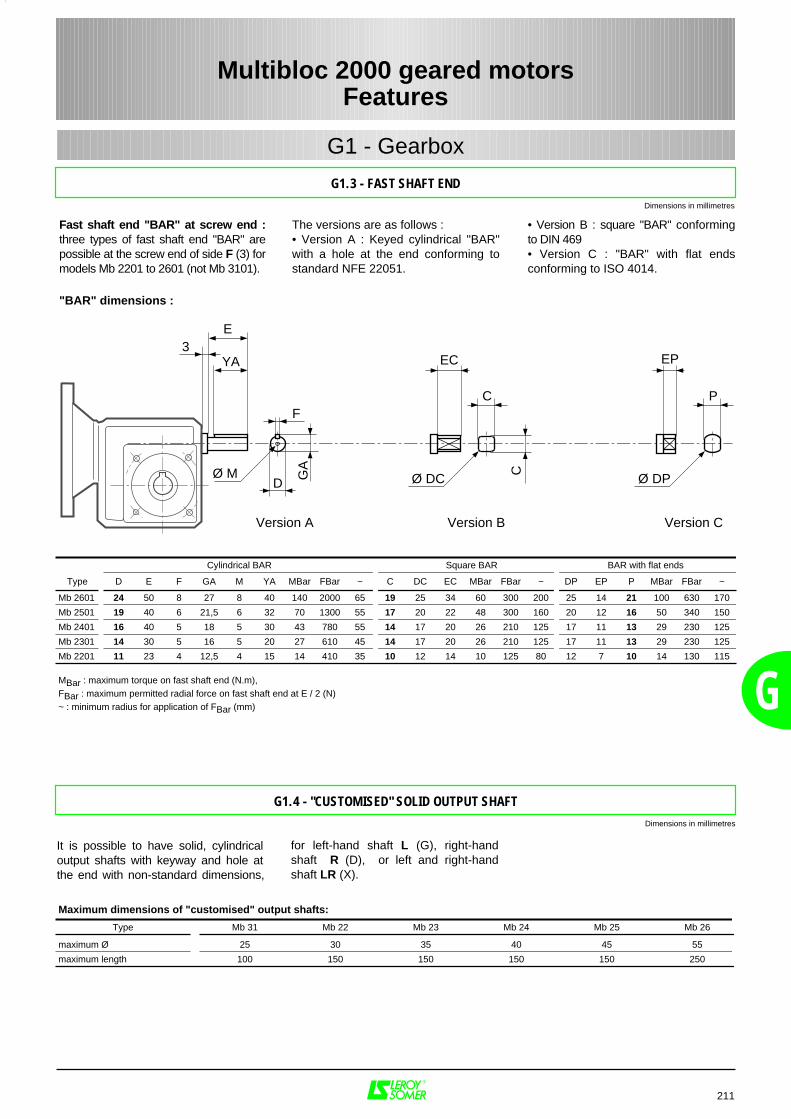
G
211
Multibloc 2000 geared motorsFeatures
G1.3 - FAST SHAFT END
G1 - Gearbox
G1.4 - "CUSTOMISED" SOLID OUTPUT SHAFT
• Version B : square "BAR" conformingto DIN 469• Version C : "BAR" with flat endsconforming to ISO 4014.
The versions are as follows :• Version A : Keyed cylindrical "BAR"with a hole at the end conforming tostandard NFE 22051.
Ø M
F
3E
YA
GA
D
EC
C
C
Ø DC
EP
P
Ø DP
Version A Version B Version C
Fast shaft end "BAR" at screw end :three types of fast shaft end "BAR" arepossible at the screw end of side F (3) formodels Mb 2201 to 2601 (not Mb 3101).
"BAR" dimensions :
Cylindrical BAR Square BAR BAR with flat ends
Type D E F GA M YA MBar FBar ~ C DC EC MBar FBar ~ DP EP P MBar FBar ~
Mb 2601 24 50 8 27 8 40 140 2000 65 19 25 34 60 300 200 25 14 21 100 630 170
Mb 2501 19 40 6 21,5 6 32 70 1300 55 17 20 22 48 300 160 20 12 16 50 340 150
Mb 2401 16 40 5 18 5 30 43 780 55 14 17 20 26 210 125 17 11 13 29 230 125
Mb 2301 14 30 5 16 5 20 27 610 45 14 17 20 26 210 125 17 11 13 29 230 125
Mb 2201 11 23 4 12,5 4 15 14 410 35 10 12 14 10 125 80 12 7 10 14 130 115
MBar : maximum torque on fast shaft end (N.m), FBar : maximum permitted radial force on fast shaft end at E / 2 (N) ~ : minimum radius for application of FBar (mm)
for left-hand shaft L (G), right-handshaft R (D), or left and right-handshaft LR (X).
It is possible to have solid, cylindricaloutput shafts with keyway and hole atthe end with non-standard dimensions,
Maximum dimensions of "customised" output shafts:
Type Mb 31 Mb 22 Mb 23 Mb 24 Mb 25 Mb 26
maximum Ø 25 30 35 40 45 55
maximum length 100 150 150 150 150 250
Dimensions in millimetres
Dimensions in millimetres
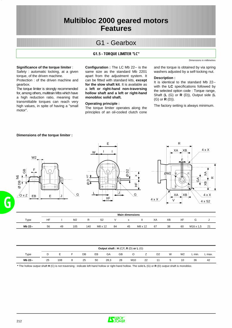
G
212
Multibloc 2000 geared motorsFeatures
G1.5 - TORQUE LIMITER "LC"
G1 - Gearbox
Significance of the torque limiter : Safety : automatic locking, at a giventorque, of the driven machine.Protection : of the driven machine andgearbox.The torque limiter is strongly recommendedfor, among others, multitrain Mbs which havea high reduction ratio, meaning thattransmittable torques can reach veryhigh values, in spite of having a "smallmotor".
Dimensions of the torque limiter :
Configuration : The LC Mb 22-- is thesame size as the standard Mb 2201apart from the adjustment system. Itcan be fitted with standard kits, exceptfor the slow shaft kit. It is available asa left or right-hand non-traversinghollow shaft and a left or right-handmonobloc solid shaft.
Operating principle :The torque limiter operates along theprinciples of an oil-cooled clutch cone
and the torque is obtained by via springwashers adjusted by a self-locking nut.
Description :It is identical to the standard Mb 22--with the LC specifications followed bythe selected option code : Torque range,Shaft (L (G) or R (D)), Output side (L(G) or R (D)).
The factory setting is always minimum.
R
XA XB 4 x X
F
4 x X4 x X
4 x S2
R
XA
XBG
AXA XB
V
I I
E
Ø D
2
xH
F
XF
Ø D
H7
J GLEEB
F
Ø D
B
GB
h6
O x Z
W2
J G
W
ØM2
Main dimensions
Type HF I M2 R S2 V x X XA XB XF G J
Mb 22-- 56 49 105 140 M8 x 12 84 45 M8 x 12 67 38 60 M16 x 1,5 21
Output shaft : H (C)*, R (D) or L (G)
Type D E F DB EB GA GB O Z D2 W W2 L min. L max.
Mb 22-- 25 108 8 25 50 28,3 28 M10 22 11 5 10 36 42
* The hollow output shaft H (C) is not traversing : indicate left-hand hollow or right-hand hollow. The solid L (G) or R (D) output shaft is monobloc.
Dimensions in millimetres
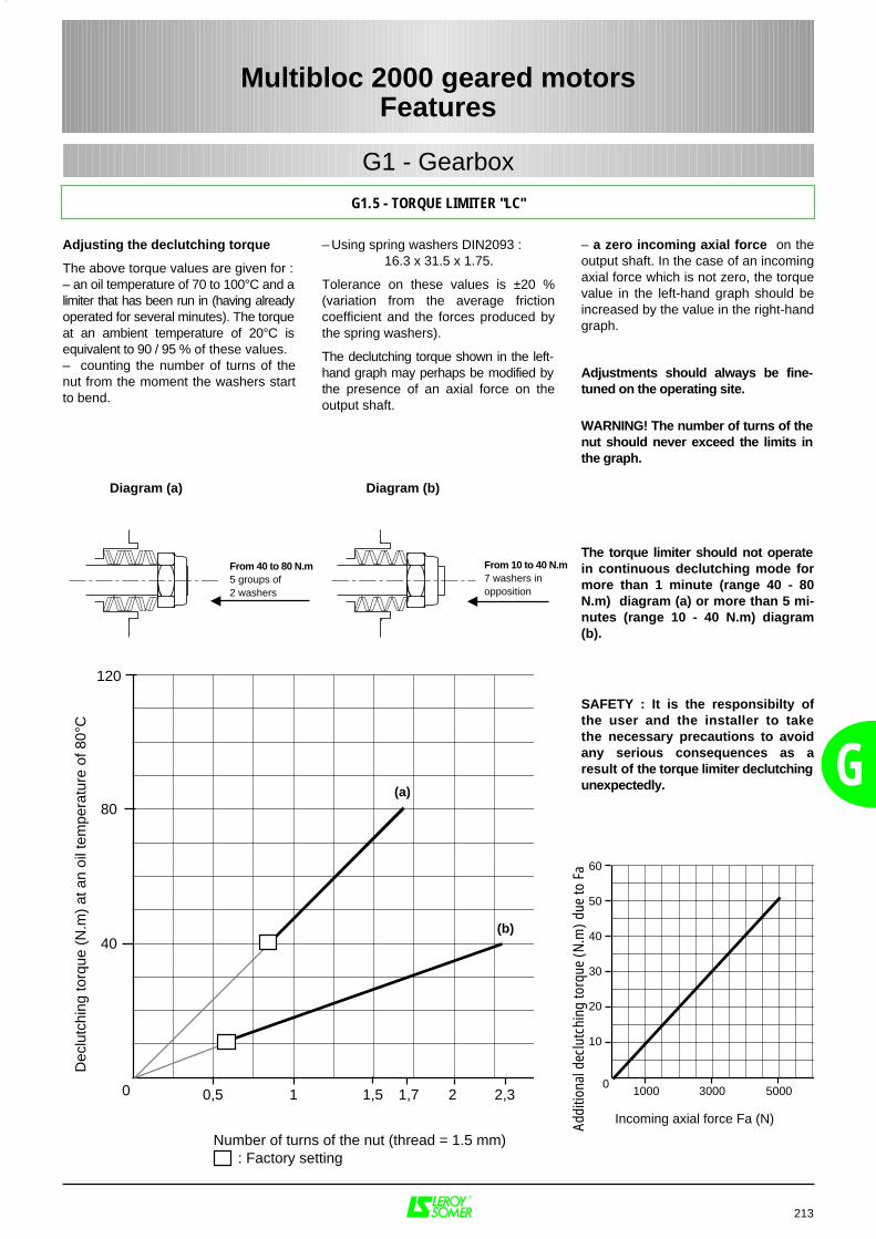
G
213
Multibloc 2000 geared motorsFeatures
G1.5 - TORQUE LIMITER "LC"
G1 - Gearbox
Adjusting the declutching torque
The above torque values are given for :– an oil temperature of 70 to 100°C and alimiter that has been run in (having alreadyoperated for several minutes). The torqueat an ambient temperature of 20°C isequivalent to 90 / 95 % of these values.– counting the number of turns of thenut from the moment the washers startto bend.
– Using spring washers DIN2093 : 16.3 x 31.5 x 1.75.
Tolerance on these values is ±20 %(variation from the average frictioncoefficient and the forces produced bythe spring washers).
The declutching torque shown in the left-hand graph may perhaps be modified bythe presence of an axial force on theoutput shaft.
– a zero incoming axial force on theoutput shaft. In the case of an incomingaxial force which is not zero, the torquevalue in the left-hand graph should beincreased by the value in the right-handgraph.
Adjustments should always be fine-tuned on the operating site.
WARNING! The number of turns of thenut should never exceed the limits inthe graph.
The torque limiter should not operatein continuous declutching mode formore than 1 minute (range 40 - 80N.m) diagram (a) or more than 5 mi-nutes (range 10 - 40 N.m) diagram(b).
SAFETY : It is the responsibilty ofthe user and the installer to takethe necessary precautions to avoidany serious consequences as aresult of the torque limiter declutchingunexpectedly.
0
Number of turns of the nut (thread = 1.5 mm) : Factory setting
Dec
lutc
hing
torq
ue (
N.m
) at
an
oil t
empe
ratu
re o
f 80°
C
0
Incoming axial force Fa (N)Addi
tiona
l dec
lutc
hing
torq
ue (N
.m) d
ue to
Fa
From 40 to 80 N.m5 groups of 2 washers
From 10 to 40 N.m7 washers inopposition
Diagram (a) Diagram (b)
(a)
(b)
120
80
40
0,5 1 1,5 21,7 2,3
60
50
40
30
20
10
1000 3000 5000
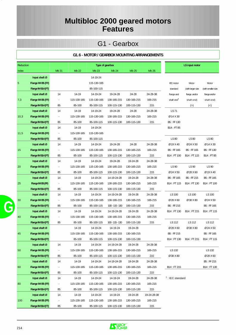
G
214
Multibloc 2000 geared motorsFeatures
G1.6 - MOTOR / GEARBOX MOUNTING ARRANGEMENTS
G1 - Gearbox
Reduction Type of gearbox LS input motor
index Mb 31 Mb 22 Mb 23 Mb 24 Mb 25 Mb 26
Input shaft Ø 14-19-24
5 Flange IM B5 (FF) 115-130-165 IEC motor Motor Motor
Flange IM B14 (FT) 85-100-115 standard (with larger size (with smaller size
Input shaft Ø 14 14-19 14-19-24 19-24-28 24-28 24-28-38 flange and flange and/or flange and/or
7,3 Flange IM B5 (FF) - 115-130-165 115-130-165 130-165-215 130-165-215 165-215 shaft end1 shaft end) shaft end)
Flange IM B14 (FT) 85 85-100 85-100-115 100-115-130 100-115-130 215 (>) (<)
Input shaft Ø 14 14-19 14-19-24 19-24-28 24-28 24-28-38 LS 71
10,3 Flange IM B5 (FF) - 115-130-165 115-130-165 130-165-215 130-165-215 165-215 Ø 14 X 30
Flange IM B14 (FT) 85 85-100 85-100-115 100-115-130 100-115-130 215 B5 : FF 130
Input shaft Ø 14 14-19 14-19-24 B14 : FT 85
11,5 Flange IM B5 (FF) - 115-130-165 115-130-165
Flange IM B14 (FT) 85 85-100 85-100-115 LS 80 LS 80 LS 80
Input shaft Ø 14 14-19 14-19-24 19-24-28 24-28 24-28-38 Ø 19 X 40 Ø 24 X 50 Ø 14 X 30
15 Flange IM B5 (FF) - 115-130-165 115-130-165 130-165-215 130-165-215 165-215 B5 : FF 165 B5 : FF 165 B5 : FF 130
Flange IM B14 (FT) 85 85-100 85-100-115 100-115-130 100-115-130 215 B14 : FT 100 B14 : FT 115 B14 : FT 85
Input shaft Ø 14 14-19 14-19-24 19-24-28 19-24-28 24-28-38
20 Flange IM B5 (FF) - 115-130-165 115-130-165 130-165-215 130-165-215 165-215 LS 90 LS 90 LS 90
Flange IM B14 (FT) 85 85-100 85-100-115 100-115-130 100-115-130 215 Ø 24 X 50 Ø 28 X 60 Ø 19 X 40
Input shaft Ø 14 14-19 14-19-24 14-19-24-28 19-24-28 24-28-38 B5 : FF 165 B5 : FF 215 B5 : FF 165
25 Flange IM B5 (FF) - 115-130-165 115-130-165 130-165-215 130-165-215 165-215 B14 : FT 115 B14 : FT 130 B14 : FT 100
Flange IM B14 (FT) 85 85-100 85-100-115 100-115-130 100-115-130 215
Input shaft Ø 14 14-19 14-19-24 14-19-24-28 19-24-28 24-28-38 LS 100 LS 100 LS 100
30 Flange IM B5 (FF) - 115-130-165 115-130-165 130-165-215 130-165-215 165-215 Ø 28 X 60 Ø 38 X 80 Ø 24 X 50
Flange IM B14 (FT) 85 85-100 85-100-115 100 - 115 - 130 100-115-130 215 B5 : FF 215 B5 : FF 165
Input shaft Ø 14 14-19 14-19-24 14-19-24-28 19-24-28 24-28-38 B14 : FT 130 B14 : FT 215 B14 : FT 115
40 Flange IM B5 (FF) - 115-130-165 115-130-165 130-165-215 130-165-215 165-215
Flange IM B14 (FT) 85 85-100 85-100-115 100 - 115 - 130 100-115-130 215 LS 112 LS 112 LS 112
Input shaft Ø 14-19 14-19-24 14-19-24 19-24-28 Ø 28 X 60 Ø 38 X 80 Ø 24 X 50
45 Flange IM B5 (FF) 115-130-165 115-130-165 130-165-215 130-165-215 B5 : FF 215 B5 : FF 165
Flange IM B14 (FT) 85-100 85-100-115 100-115-130 100-115-130 B14 : FT 130 B14 : FT 215 B14 : FT 115
Input shaft Ø 14 14-19 14-19-24 14-19-24-28 19-24-28 24-28-38
50 Flange IM B5 (FF) - 115-130-165 115-130-165 130-165-215 130-165-215 165-215 LS 132 LS 132
Flange IM B14 (FT) 85 85-100 85-100-115 100-115-130 100-115-130 215 Ø 38 X 80 Ø 28 X 60
Input shaft Ø 14 14-19 14-19-24 14-19-24-28 19-24-28 24-28-38 B5 : FF 215
60 Flange IM B5 (FF) - 115-130-165 115-130-165 130-165-215 130-165-215 165-215 B14 : FT 215 B14 : FT 130
Flange IM B14 (FT) 85 85-100 85-100-115 100-115-130 100-115-130 215
Input shaft Ø 14 14-19 14-19-24 14-19-24 19-24-28 24-28-38 1 : IEC standard
80 Flange IM B5 (FF) - 115-130-165 115-130-165 130-165-215 130-165-215 165-215
Flange IM B14 (FT) 85 85-100 85-100-115 100-115-130 100-115-130 215
Input shaft Ø 14 14-19 14-19-24 14-19-24 19-24-28 19-24-28-38
100 Flange IM B5 (FF) - 115-130-165 115-130-165 130-165-215 130-165-215 165-215
Flange IM B14 (FT) 85 85-100 85-100-115 100-115-130 100-115-130 215
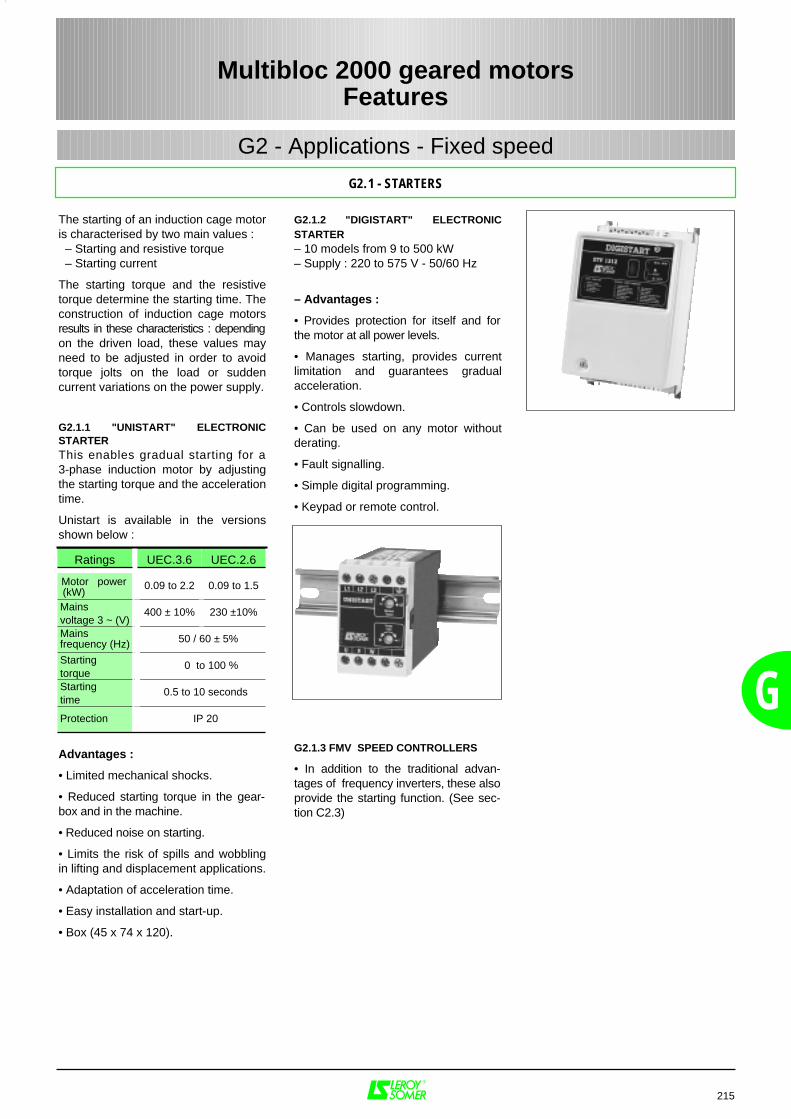
G
215
Multibloc 2000 geared motorsFeatures
G2.1 - STARTERS
G2 - Applications - Fixed speed
G2.1.2 "DIGISTART" ELECTRONICSTARTER– 10 models from 9 to 500 kW– Supply : 220 to 575 V - 50/60 Hz
– Advantages :
• Provides protection for itself and forthe motor at all power levels.
• Manages starting, provides currentlimitation and guarantees gradualacceleration.
• Controls slowdown.
• Can be used on any motor withoutderating.
• Fault signalling.
• Simple digital programming.
• Keypad or remote control.
G2.1.3 FMV SPEED CONTROLLERS
• In addition to the traditional advan-tages of frequency inverters, these alsoprovide the starting function. (See sec-tion C2.3)
The starting of an induction cage motoris characterised by two main values : – Starting and resistive torque – Starting current
The starting torque and the resistivetorque determine the starting time. Theconstruction of induction cage motorsresults in these characteristics : dependingon the driven load, these values mayneed to be adjusted in order to avoidtorque jolts on the load or suddencurrent variations on the power supply.
G2.1.1 "UNISTART" ELECTRONICSTARTERThis enables gradual starting for a3-phase induction motor by adjustingthe starting torque and the accelerationtime.
Unistart is available in the versionsshown below :
Advantages :
• Limited mechanical shocks.
• Reduced starting torque in the gear-box and in the machine.
• Reduced noise on starting.
• Limits the risk of spills and wobblingin lifting and displacement applications.
• Adaptation of acceleration time.
• Easy installation and start-up.
• Box (45 x 74 x 120).
Ratings UEC.3.6 UEC.2.6
Motor power(kW)
0.09 to 2.2 0.09 to 1.5
Mainsvoltage 3 ~ (V)
400 ± 10% 230 ±10%
Mainsfrequency (Hz) 50 / 60 ± 5%
Startingtorque
0 to 100 %
Starting time
0.5 to 10 seconds
Protection IP 20
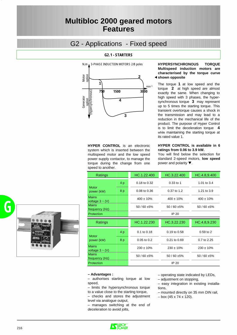
HYPERSYNCHRONOUS TORQUEMultispeed induction motors arecharacterised by the torque curveshown opposite
The torque 1 at low speed and thetorque 2 at high speed are almostexactly the same. When changing tohigh speed with 3 phases, the hyper-synchronous torque 3 may representup to 5 times the starting torque. Thistransient overtorque causes a shock inthe transmission and may lead to areduction in the mechanical life of theproduct. The purpose of Hyper Controlis to limit the deceleration torque 4while maintaining the starting torque atits rated value 1.
HYPER CONTROL is available in 6ratings from 0.06 to 3.9 kW.You will find below the selection forstandard 2-speed motors, low speedpower and polarity .
– operating state indicated by LEDs,– adjustment on stopping,– easy integration in existing installa-tions,– mounted directly on 35 mm DIN rail,– box (45 x 74 x 120).
G
216
Multibloc 2000 geared motorsFeatures
G2.1 - STARTERS
G2 - Applications - Fixed speed
HYPER CONTROL is an electronicsystem which is inserted between themultispeed motor and the low speedpower supply contactor, to manage thetorque during the change from onespeed to another.
– Advantages : – authorises starting torque at lowspeed,– limits the hypersynchronous torqueto a value close to the starting torque,– checks and stores the adjustmentlevel via analogue output,– manages switching at the end ofdeceleration to avoid jolts,
Ratings HC.1.22.400 HC.3.22.400 HC.4.8,9.400
4 p 0.18 to 0.32 0.33 to 1 1.01 to 3.4
8 p 0.08 to 0.36 0.37 to 1.2 1.21 to 3.9
Mains voltage 3 ~ (V)
400 ± 10% 400 ± 10% 400 ± 10%
Mainsfrequency (Hz)
50 / 60 ±5% 50 / 60 ±5% 50 / 60 ±5%
Protection IP 20
Ratings HC.1.22.230 HC.3.22.230 HC.4.8,9.230
4 p 0.1 to 0.18 0.19 to 0.58 0.59 to 2
8 p 0.05 to 0.2 0.21 to 0.69 0.7 to 2.25
Mains voltage 3 ~ (V)
230 ± 10% 230 ± 10% 230 ± 10%
Mainsfrequency (Hz)
50 / 60 ±5% 50 / 60 ±5% 50 / 60 ±5%
Protection IP 20
1
2
4
min-1
3
N.m 3-PHASE INDUCTION MOTORS 2/8 poles
Mot
orop
tion
Gene
rato
rop
tion
(hyp
ersy
nchr
onou
s) 1500750 3000
Motor power (kW)
Motor power (kW)
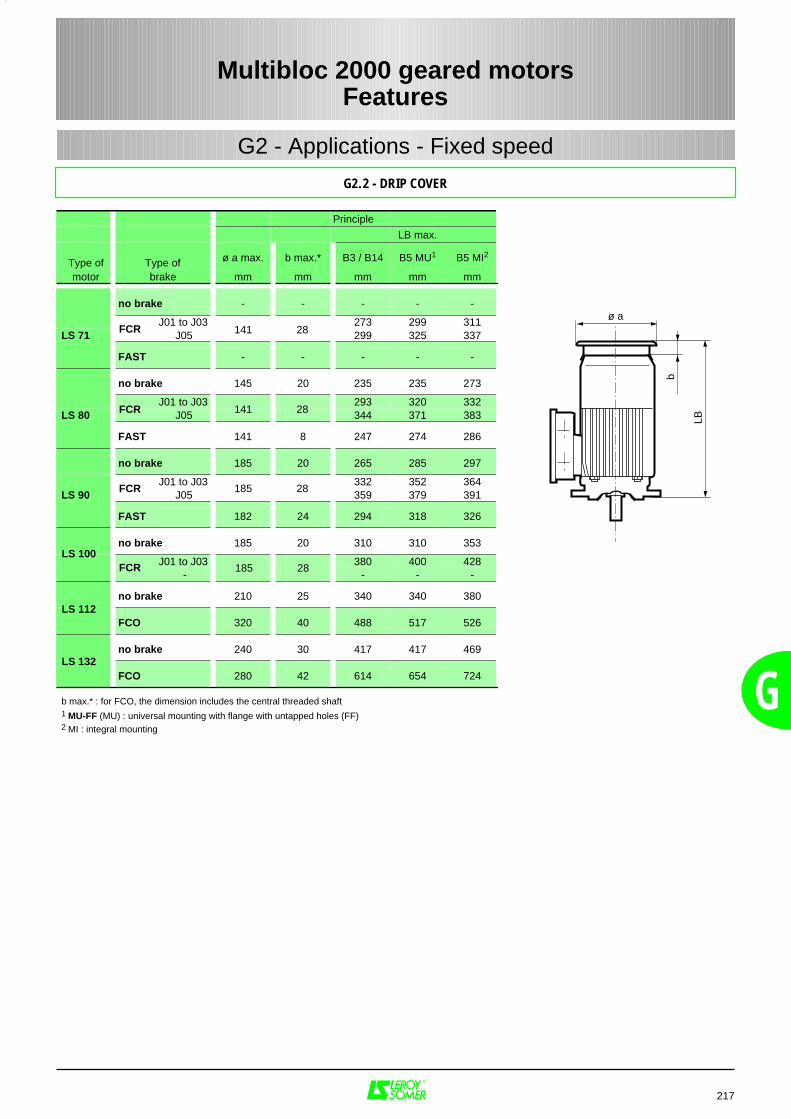
G
217
Multibloc 2000 geared motorsFeatures
G2.2 - DRIP COVER
G2 - Applications - Fixed speed
Principle
LB max.
Type of Type of ø a max. b max.* B3 / B14 B5 MU1 B5 MI2
motor brake mm mm mm mm mm
no brake - - - - -
J01 to J03 273 299 311LS 71 J05 299 325 337
FAST - - - - -
no brake 145 20 235 235 273
J01 to J03 293 320 332LS 80 J05 344 371 383
FAST 141 8 247 274 286
no brake 185 20 265 285 297
J01 to J03 332 352 364LS 90 J05 359 379 391
FAST 182 24 294 318 326
no brake 185 20 310 310 353
J01 to J03 380 400 428- - - -
no brake 210 25 340 340 380
FCO 320 40 488 517 526
no brake 240 30 417 417 469
FCO 280 42 614 654 724
b max.* : for FCO, the dimension includes the central threaded shaft1 MU-FF (MU) : universal mounting with flange with untapped holes (FF)2 MI : integral mounting
b
LB
ø aFCR 141 28
FCR 141 28
FCR 185 28
LS 100
LS 112
LS 132
FCR 185 28
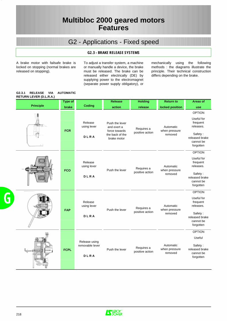
G
A brake motor with failsafe brake islocked on stopping (normal brakes arereleased on stopping).
218
Multibloc 2000 geared motorsFeatures
G2.3 - BRAKE RELEASE SYSTEMS
G2 - Applications - Fixed speed
mechanically using the followingmethods : the diagrams illustrate theprinciple. Their technical constructiondiffers depending on the brake.
To adjust a transfer system, a machineor manually handle a device, the brakemust be released. The brake can bereleased either electrically (DE) bysupplying power to the electromagnet(separate power supply obligatory), or
PrincipleType of
brake CodingRelease
action
Holding
release
Return to
locked position
Areas of
use
OPTION
Release using lever
D L R A
OPTION
Release using lever
D L R A
OPTION
Release using lever
D L R A
OPTION
Release usingremovable lever
D L R A
Automatic when pressure
removed
Useful forfrequent
releases.
Safety :released brake
cannot beforgotten
Push the leverand exert a force towards
the back of thebrake motor
Requires a positive action
Push the lever
Push the lever
Push the lever
Requires a positive action
Requires a positive action
Requires a positive action
Automatic when pressure
removed
Automatic when pressure
removed
Automatic when pressure
removed
Useful forfrequent
releases.
Safety :released brake
cannot beforgotten
Useful forfrequent
releases.
Safety :released brake
cannot beforgotten
Useful
Safety :released brake
cannot beforgotten
FCR
FCO
FAP
FCPL
G2.3.1 RELEASE VIA AUTOMATICRETURN LEVER (D.L.R.A.)
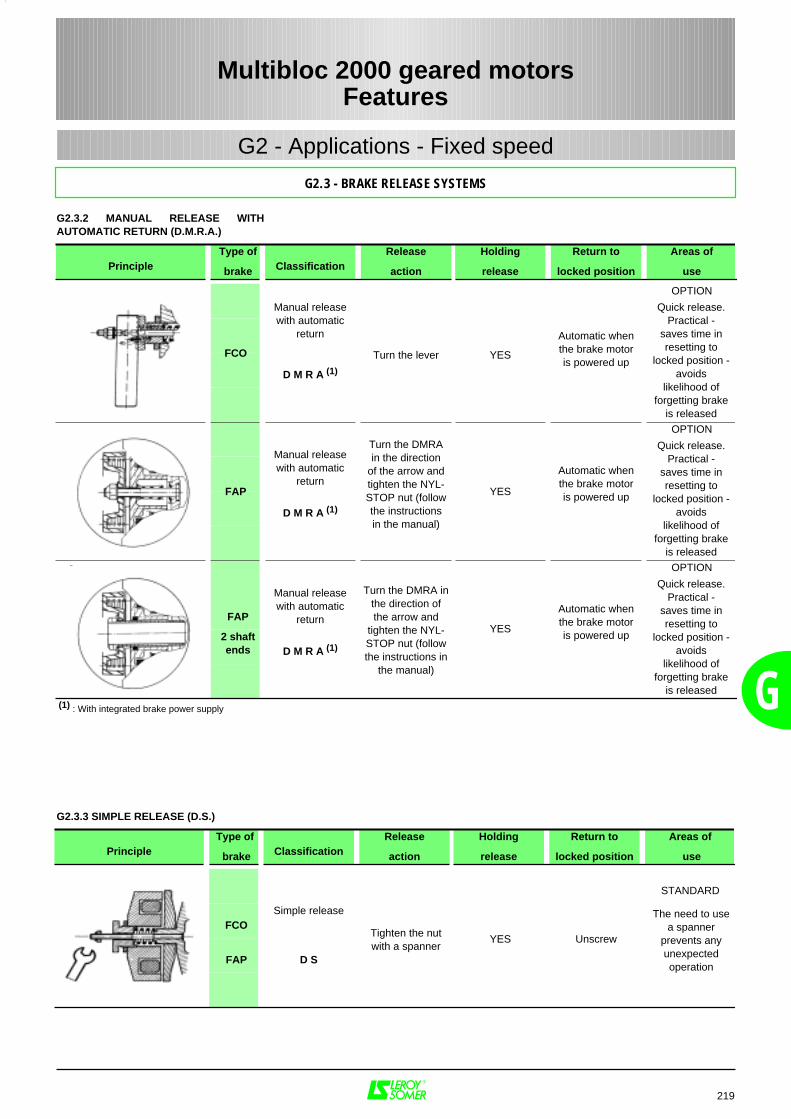
G
G2.3.2 MANUAL RELEASE WITHAUTOMATIC RETURN (D.M.R.A.)
219
Multibloc 2000 geared motorsFeatures
G2.3 - BRAKE RELEASE SYSTEMS
G2 - Applications - Fixed speed
PrincipleType of
brake ClassificationRelease
action
Holding
release
Return to
locked position
Areas of
use
OPTION
D M R A (1)
OPTION
D M R A (1)
OPTION
FAP
2 shaftends D M R A (1)
(1) : With integrated brake power supply
Manual releasewith automatic
return
FCO
FAP
Turn the lever YES
Automatic whenthe brake motoris powered up
Quick release.Practical -
saves time inresetting to
locked position -avoids
likelihood offorgetting brake
is released
Manual releasewith automatic
return
Manual releasewith automatic
return
Turn the DMRAin the direction
of the arrow andtighten the NYL-STOP nut (followthe instructionsin the manual)
YES
YES
Automatic whenthe brake motoris powered up
Automatic whenthe brake motoris powered up
Quick release.Practical -
saves time inresetting to
locked position -avoids
likelihood offorgetting brake
is released
Quick release.Practical -
saves time inresetting to
locked position -avoids
likelihood offorgetting brake
is released
Turn the DMRA inthe direction ofthe arrow and
tighten the NYL-STOP nut (followthe instructions in
the manual)
PrincipleType of
brake ClassificationRelease
action
Holding
release
Return to
locked position
Areas of
use
STANDARD
FCOSimple release
FAP D S
Tighten the nutwith a spanner
YES Unscrew
The need to usea spanner
prevents anyunexpectedoperation
G2.3.3 SIMPLE RELEASE (D.S.)
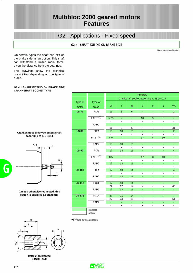
G2.4.1 SHAFT EXITING ON BRAKE SIDECRANKSHAFT SOCKET TYPE
G
On certain types the shaft can exit onthe brake side as an option. This shaftcan withstand a limited radial force,given the distance from the bearings.
The drawings show the technicalpossibilities depending on the type ofbrake.
220
Multibloc 2000 geared motorsFeatures
G2.4 - SHAFT EXITING ON BRAKE SIDE
G2 - Applications - Fixed speed
Principle
Crankshaft socket according to ISO 4014Type of
motor
Type of
brake Ø f g q s t VA
LS 71 FCR 11 8 6 - - - 2- - - - - - -
FAST (1) 5,25 - - 10 5 5 -- - - - - - -
FAP2 - - - - - - -11 8 6 - - - 31
LS 80 FCR 13 10 7 - - - 2- - - - - - -
FAST (1) 8,5 - - 17 8 10 -- - - - - - -
FAP2 13 10 7 - - - -- - - - - - -
LS 90 FCR 17 13 11 - - - 4- - - - - - -
FAST (1) 8,5 - - 17 8 10 -- - - - - - -
FAP2 17 13 11 - - - -- - - - - - -
LS 100 FCR 17 13 11 - - - 4- - - - - - -
FAP2 17 13 11 - - - -- - - - - - -
LS 112 FCO 17 13 11 - - - -22 17 14 - - - 48
FAP2 17 13 11 - - - -- - - - - - -
LS 132 FCO 27 21 14 - - - -27 23 18 - - - 51
FAP2 - - - - - - -- - - - - - -
standardoption
(1) See details opposite
gVA
f
ø
Crankshaft socket type output shaft according to ISO 4014
(unless otherwise requested, thisoption is supplied as standard)
60°
s
q
t
1
Ø
Detail of socket head(special FAST)
Dimensions in millimetres
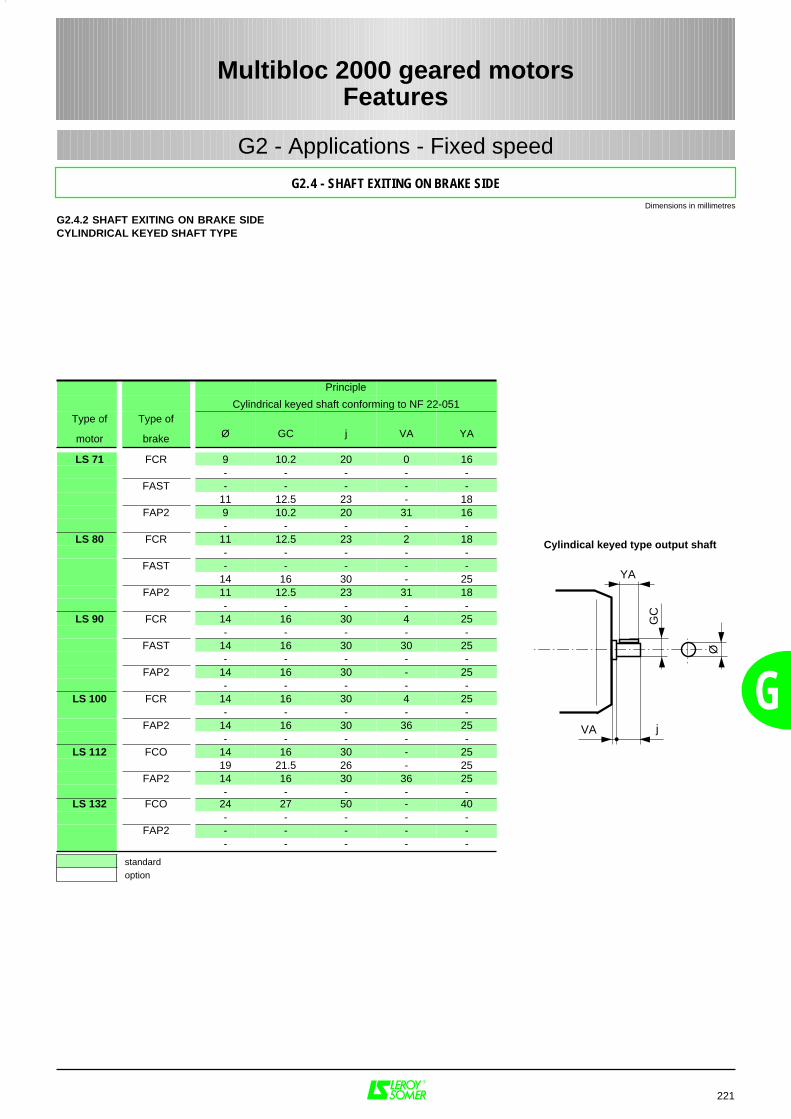
G
221
Multibloc 2000 geared motorsFeatures
G2.4 - SHAFT EXITING ON BRAKE SIDE
G2 - Applications - Fixed speed
G2.4.2 SHAFT EXITING ON BRAKE SIDECYLINDRICAL KEYED SHAFT TYPE
Principle
Cylindrical keyed shaft conforming to NF 22-051Type of
motor
Type of
brake Ø GC j VA YA
LS 71 FCR 9 10.2 20 0 16- - - - -
FAST - - - - -11 12.5 23 - 18
FAP2 9 10.2 20 31 16- - - - -
LS 80 FCR 11 12.5 23 2 18- - - - -
FAST - - - - -14 16 30 - 25
FAP2 11 12.5 23 31 18- - - - -
LS 90 FCR 14 16 30 4 25- - - - -
FAST 14 16 30 30 25- - - - -
FAP2 14 16 30 - 25- - - - -
LS 100 FCR 14 16 30 4 25- - - - -
FAP2 14 16 30 36 25- - - - -
LS 112 FCO 14 16 30 - 2519 21.5 26 - 25
FAP2 14 16 30 36 25- - - - -
LS 132 FCO 24 27 50 - 40- - - - -
FAP2 - - - - -- - - - -
standardoption
jØ
GC
YA
VA
Cylindical keyed type output shaft
Dimensions in millimetres
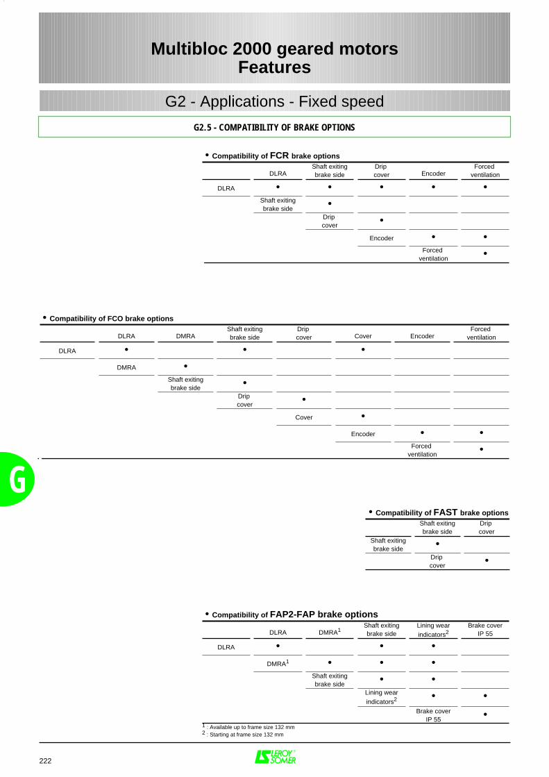
G
222
Multibloc 2000 geared motorsFeatures
G2.5 - COMPATIBILITY OF BRAKE OPTIONS
G2 - Applications - Fixed speed
• Compatibility of FCR brake options
DLRAShaft exitingbrake side
Drip cover Encoder
Forced ventilation
DLRA • • • • •Shaft exitingbrake side •
Drip cover •
Encoder • •Forced
ventilation •
• Compatibility of FCO brake options
DLRA DMRAShaft exitingbrake side
Drip cover Cover Encoder
Forced ventilation
DLRA • • •
DMRA •Shaft exitingbrake side •
Drip cover •
Cover •
Encoder • •Forced
ventilation •
• Compatibility of FAST brake optionsShaft exitingbrake side
Drip cover
Shaft exitingbrake side •
Drip cover •
• Compatibility of FAP2-FAP brake options
DLRA DMRA1Shaft exitingbrake side
Lining wearindicators2
Brake coverIP 55
DLRA • • •
DMRA1 • • •Shaft exitingbrake side • •
Lining wearindicators2 • •
Brake coverIP 55 •
1 : Available up to frame size 132 mm2 : Starting at frame size 132 mm
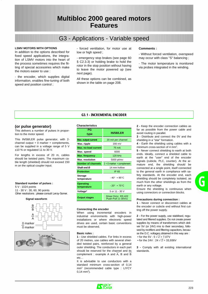
G
LSMV MOTORS WITH OPTIONSIn addition to the options described forfixed speed applications, the integra-tion of LSMV motors into the heart ofthe process sometimes requires the fit-ting of special accesoiries which makethe motors easier to use :
- the encoder, which supplies digitalinformation, enables fine-tuning of bothspeed and position control ;
223
Multibloc 2000 geared motorsFeatures
G3.1 - INCREMENTAL ENCODER
G3 - Applications - Variable speed
Comments :
- Without forced ventilation, overspeedmay occur with class "S" balancing ;
- The motor temperature is monitoredvia probes integrated in the winding.
- forced ventilation, for motor use atlow or high speed ;
- emergency stop brakes (see page 60§ C2.3.3) or holding brake to hold therotor in the stop position without havingto leave the motor powered up (seenext page).
All these options can be combined, asshown in the table on page 208.
(or pulse generator)This delivers a number of pulses in propor-tion to the motor speed.
This IN/58/LER pulse generator, with 2-channel output + 0 marker + complements,can be supplied in a voltage range of 5 V±10 % or regulated 11 to 30 V.
For lengths in excess of 20 m, cablesshould be twisted pairs. The maximum ca-ble length (shielded) should not exceed 150m on the optical coupler input.
BB
AA
0 marker0 marker
Signal waveform
Characteristics
PG
type
Max. output current 20 mA per channel
Max. ripple 200 mV
Max. no-load current 75 mA
Max. speed 6000
Max. frequency 120 kHz
Max. resolution 5000 pt/rev
Nomber of channels 2 + 0 marker + complement
Shaft end Ø 14 mm hollow
Protection IP 65
Storagetemperature - 40° + 85°C
Operatingtemperature - 20° + 75°C
Voltage* 5 or 11 - 30 V
Output stages Driver 5Vcc RS 422Push-Pull 11-30Vcc
Standard number of pulses :5 V : 1024 points11 - 30 V : 30, 60, 90 pointsOther resolutions : please consult Leroy-Somer.
IN/58/LER
Connecting the encoderWhen using incremental encoders inindustrial environments with high-powerinstallations or where electronic speeddrives are used, certain basic conventionsmust be observed.
Basic rules :1 - Use shielded cables. For links in excessof 20 metres, use cables with several shiel-ded twisted pairs, reinforced by a generalouter shielding. The conductors in each partshould be reserved for the channel and itscomplement : example A and A, B and Betc…It is advisable to use conductors with astandard minimum cross-section of 0,14mm2 (recommended cable type : LIYCY0,14 mm2).
2 - Keep the encoder connection cables asfar as possible from the power cable andavoid routing in parallel.3 - Distribute and connect the 0V and theshielding in a "star" formation.4 - Earth the shielding using cables with aminimum cross-section of 4 mm2.5 - Never connect shielding to earth at bothends. Ideally, connect a shielded cable toearth at the "user" end of the encodersignals (cubicle, PLC, counter). At the ar-mature end, the shielding should beconnected at a single point, itself connectedto the general earth in compliance with sa-fety standards. At the encoder end, eachshielding should be completety isolated, asmuch from the other shieldings as from theearth or any voltage.Ensure the shielding is continuous whenusing connectors or connection blocks.
Precautions during connection :1 - Never connect or disconnect cables atthe encoder or cubicle end without first cut-ting off the power supply.
2 - For the power supply, use stabilised, regu-lated and filtered supplies. Do not create powersupplies by means of transformers which deli-ver 5V (or 24V) rms to their secondary, follo-wed by rectifiers and filtering capacitors, becau-se the D.C. voltages obtained in this way are : • for the 5V : 5 √ 2 = 7,07V • for the 24V : 24 √ 2 = 33,936V
3 - Comply with all existing internationalstandards.
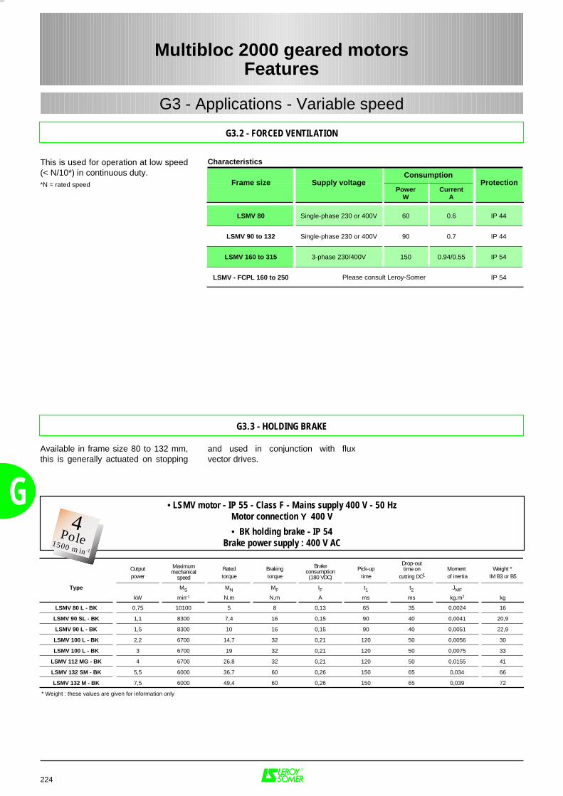
Characteristics
G
This is used for operation at low speed(< N/10*) in continuous duty.*N = rated speed
224
Multibloc 2000 geared motorsFeatures
G3.2 - FORCED VENTILATION
G3 - Applications - Variable speed
PowerW
CurrentA
LSMV 80 Single-phase 230 or 400V 60 0.6 IP 44
LSMV 90 to 132 Single-phase 230 or 400V 90 0.7 IP 44
LSMV 160 to 315 3-phase 230/400V 150 0.94/0.55 IP 54
LSMV - FCPL 160 to 250 IP 54
ConsumptionFrame size
Please consult Leroy-Somer
Supply voltage Protection
G3.3 - HOLDING BRAKE
Output Rated Braking Pick-up Moment Weight *power torque torque time of inertia IM B3 or B5
Type MS MN MF IF t1 t2 JMF
kW min-1 N.m N.m A ms ms kg.m2 kg
LSMV 80 L - BK 0,75 10100 5 8 0,13 65 35 0,0024 16
LSMV 90 SL - BK 1,1 8300 7,4 16 0,15 90 40 0,0041 20,9
LSMV 90 L - BK 1,5 8300 10 16 0,15 90 40 0,0051 22,9
LSMV 100 L - BK 2,2 6700 14,7 32 0,21 120 50 0,0056 30
LSMV 100 L - BK 3 6700 19 32 0,21 120 50 0,0075 33
LSMV 112 MG - BK 4 6700 26,8 32 0,21 120 50 0,0155 41
LSMV 132 SM - BK 5,5 6000 36,7 60 0,26 150 65 0,034 66
LSMV 132 M - BK 7,5 6000 49,4 60 0,26 150 65 0,039 72
* Weight : these values are given for information only
Maximummechanical
speed
• LSMV motor - IP 55 - Class F - Mains supply 400 V - 50 HzMotor connection ΥΥΥΥ 400 V
• BK holding brake - IP 54Brake power supply : 400 V AC
Drop-outtime on
cutting DC1
Brakeconsumption
(180 VDC)
and used in conjunction with fluxvector drives.
Available in frame size 80 to 132 mm,this is generally actuated on stopping
2Pôles3000 min-1
4Pole1500 min-1
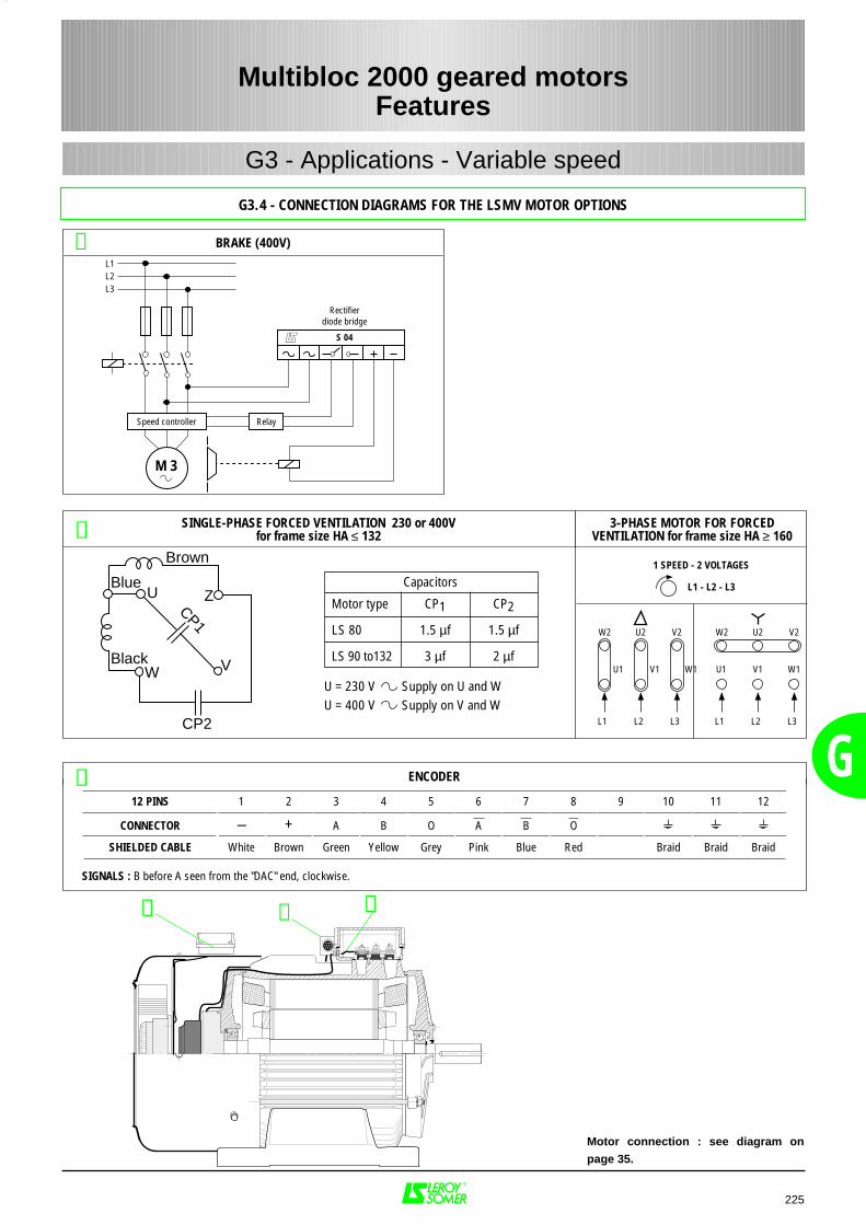
G
225
Multibloc 2000 geared motorsFeatures
G3.4 - CONNECTION DIAGRAMS FOR THE LSMV MOTOR OPTIONS
G3 - Applications - Variable speed
Motor type
Capacitors
CP1 CP2
LS 80 1.5 µf 1.5 µf
LS 90 to132
U = 230 V Supply on U and WU = 400 V Supply on V and W
3 µf 2 µf
1 SPEED - 2 VOLTAGES
L1 - L2 - L3
W2 U2 V2
L1 L2 L3
U1 V1 W1
W2 U2 V2
L1 L2 L3
U1 V1 W1
3-PHASE MOTOR FOR FORCEDVENTILATION for frame size HA ≥ 160
ENCODER
SIGNALS : B before A seen from the "DAC" end, clockwise.
12 PINS 1 2 3 4 5 6 7 8 9 10 11 12
CONNECTOR – + A B O A B O
SHIELDED CABLE White Brown Green Yellow Grey Pink Blue Red Braid Braid Braid
➂
➀➁ ➂
BRAKE (400V)➀
M 3
L1L2L3
Rectifierdiode bridge
S 04
Speed controller Relay
SINGLE-PHASE FORCED VENTILATION 230 or 400Vfor frame size HA ≤ 132➁
Brown
Blue
Black
CP2
ZU
CP1W V
Motor connection : see diagram on
page 35.
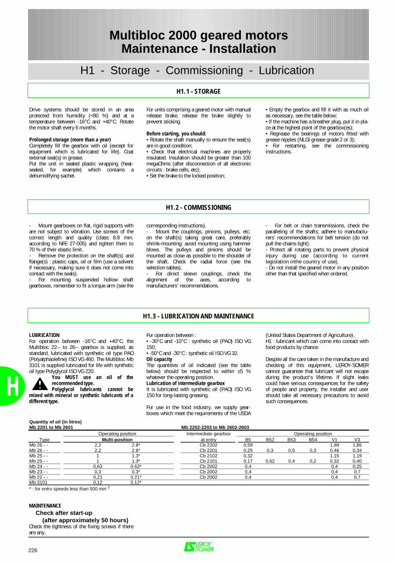
226
H
H1 - Storage - Commissioning - Lubrication
H1.1 - STORAGE
Drive systems should be stored in an areaprotected from humidity (<80 %) and at atemperature between -16°C and +40°C. Rotatethe motor shaft every 6 months.
Prolonged storage (more than a year)Completely fill the gearbox with oil (except forequipment which is lubricated for life). Coatexternal seal(s) in grease.Put the unit in sealed plastic wrapping (heat-sealed, for example) which contains adehumidifying sachet.
• Empty the gearbox and fill it with as much oilas necessary, see the table below;• If the machine has a breather plug, put it in pla-ce at the highest point of the gearbox(es);• Regrease the bearings of motors fitted withgrease nipples (NLGI grease grade 2 or 3);• For restarting, see the commissioninginstructions.
For units comprising a geared motor with manualrelease brake, release the brake slightly toprevent sticking.
Before starting, you should:• Rotate the shaft manually to ensure the seal(s)are in good condition;• Check that electrical machines are properlyinsulated. Insulation should be greater than 100megaOhms (after disconnection of all electroniccircuits : brake cells, etc);• Set the brake to the locked position;
Multibloc 2000 geared motorsMaintenance - Installation
H1.2 - COMMISSIONING
- Mount gearboxes on flat, rigid supports withare not subject to vibration. Use screws of thecorrect length and quality (class 8.8 min.according to NFE 27-005) and tighten them to70 % of their elastic limit.- Remove the protection on the shaft(s) andflange(s) : plastic caps, oil or film (use a solventif necessary, making sure it does not come intocontact with the seals).- For mounting suspended hollow shaftgearboxes, remember to fit a torque arm (see the
- For belt or chain transmissions, check theparalleling of the shafts; adhere to manufactu-rers' recommendations for belt tension (do notpull the chains tight).- Protect all rotating parts to prevent physicalinjury during use (according to currentlegislation inthe country of use).- Do not install the geared motor in any positionother than that specified when ordered.
corresponding instructions).- Mount the couplings, pinions, pulleys, etc.on the shaft(s) taking great care, preferablyshrink-mounting; avoid mounting using hammerblows. The pulleys and pinions should bemounted as close as possible to the shoulder ofthe shaft. Check the radial force (see theselection tables).- For direct sleeve couplings, check thealignment of the axes, according tomanufacturers' recommendations.
MAINTENANCE Check after start-up (after approximately 50 hours)Check the tightness of the fixing screws if thereare any.
H1.3 - LUBRICATION AND MAINTENANCE
LUBRICATIONFor operation between -16°C and +40°C, theMultibloc 22-- to 26-- gearbox is supplied, asstandard, lubricated with synthetic oil type PAO(Polyalphaolefine) ISO VG 460. The Multibloc Mb3101 is supplied lubricated for life with syntheticoil type Polyglycol ISO VG 220.
You MUST use an oil of therecommended type.Polyglycol lubricants cannot be
mixed with mineral or synthetic lubricants of adifferent type.
(United States Department of Agriculture).H1 : lubricant which can come into contact withfood products by chance.
Despite all the care taken in the manufacture andchecking of this equipment, LEROY-SOMERcannot guarantee that lubricant will not escapeduring the product's lifetime. If slight leakscould have serious consequences for the safetyof people and property, the installer and usershould take all necessary precautions to avoidsuch consequences.
For operation between :• -30°C and -10°C : synthetic oil (PAO) ISO VG150;• -50°C and -30°C : synthetic oil ISO VG 32.Oil capacityThe quantities of oil indicated (see the tablebelow) should be respected to within ±5 %whatever the operating position.Lubrication of intermediate gearboxIt is lubricated with synthetic oil (PAO) ISO VG150 for long-lasting greasing.
For use in the food industry, we supply gear-boxes which meet the requirements of the USDA
Quantity of oil (in litres)Mb 2201 to Mb 2601 Mb 2202-2203 to Mb 2602-2603
Operating position Intermediate gearbox Operating positionType Multi-position at entry B5 B52 B53 B54 V1 V3
Mb 26 - - 2,2 2.8* Cb 2202 0,59 1,99 1,85Mb 26 - - 2,2 2.8* Cb 2201 0,25 0,3 0,5 0,3 0,46 0,34Mb 25 - - 1 1.3* Cb 2102 0,32 1,15 1,19Mb 25 - - 1 1.3* Cb 2101 0,17 0,62 0,4 0,2 0,32 0,40Mb 24 - - 0,63 0.63* Cb 2002 0,4 0,4 0,25Mb 23 - - 0,3 0.3* Cb 2002 0,4 0,4 0,7Mb 22 - - 0,21 0.21* Cb 2002 0,4 0,4 0,7Mb 3101 0,12 0.12** : for entry speeds less than 500 min-1
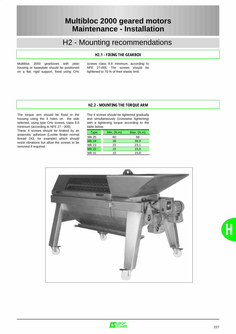
H
H2 - Mounting recommendations
H2.1 - FIXING THE GEARBOX
227
Multibloc 2000 geared motorsMaintenance - Installation
Multibloc 2000 gearboxes with plainhousing or baseplate should be positionedon a flat, rigid support, fixed using CHc
screws class 8.8 minimum, according toNFE 27-005. The screws should betightened to 70 % of their elastic limit.
H2.2 - MOUNTING THE TORQUE ARM
The torque arm should be fixed to thehousing using the 4 holes on the sideselected, using type CHc screws, class 8.8minimum (according to NFE 27 - 005).These 4 screws should be braked by ananaerobic adhesive (Loctite Brake normalthread 243, for example) which shouldresist vibrations but allow the screws to beremoved if required.
The 4 screws should be tightened graduallyand simultaneously (crosswise tightening)with a tightening torque according to thetable below.
Type Min. (N.m) Max. (N.m)
Mb 25 60 68Mb 24 38 39,9Mb 23 22 23,1Mb 22 15 15,8Mb 31 15 15,8
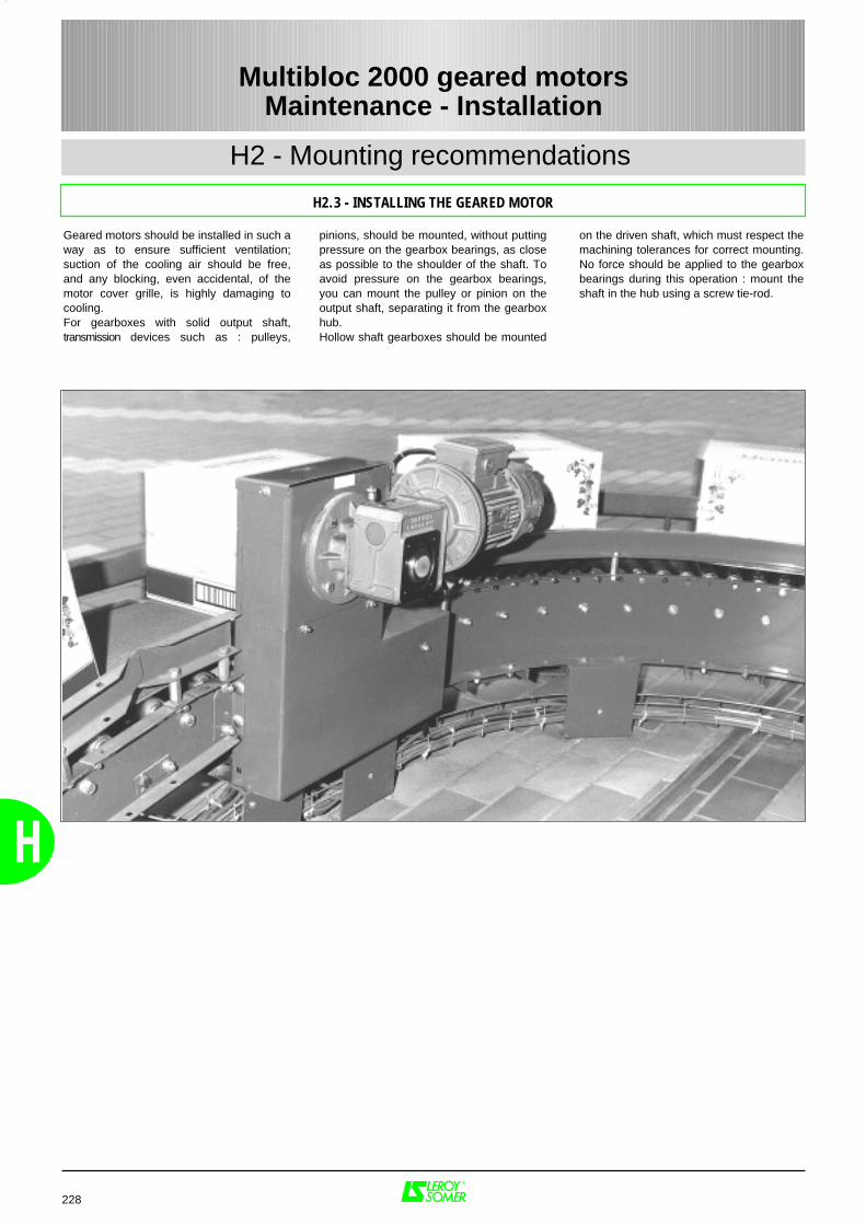
228
H
H2 - Mounting recommendations
Multibloc 2000 geared motorsMaintenance - Installation
H2.3 - INSTALLING THE GEARED MOTOR
Geared motors should be installed in such away as to ensure sufficient ventilation;suction of the cooling air should be free,and any blocking, even accidental, of themotor cover grille, is highly damaging tocooling.For gearboxes with solid output shaft,transmission devices such as : pulleys,
on the driven shaft, which must respect themachining tolerances for correct mounting.No force should be applied to the gearboxbearings during this operation : mount theshaft in the hub using a screw tie-rod.
pinions, should be mounted, without puttingpressure on the gearbox bearings, as closeas possible to the shoulder of the shaft. Toavoid pressure on the gearbox bearings,you can mount the pulley or pinion on theoutput shaft, separating it from the gearboxhub.Hollow shaft gearboxes should be mounted
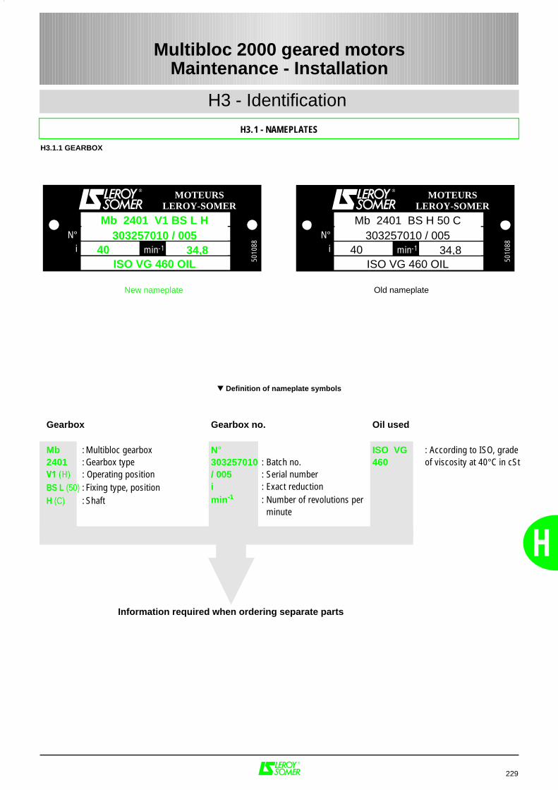
H
H3 - Identification
H3.1 - NAMEPLATES
229
Multibloc 2000 geared motorsMaintenance - Installation
Gearbox Mb : Multibloc gearbox2401 : Gearbox typeV1 (H) : Operating positionBS L (50) : Fixing type, positionH (C) : Shaft
Oil used
ISO VG : According to ISO, grade460 of viscosity at 40°C in cSt
Definition of nameplate symbols
Information required when ordering separate parts
Gearbox no.
N° 303257010 : Batch no./ 005 : Serial numberi : Exact reductionmin-1 : Number of revolutions per
minute
H3.1.1 GEARBOX
N°i min-1
MOTEURSLEROY-SOMER
5010
88
Mb 2401 V1 BS L H303257010 / 005
34,840ISO VG 460 OIL
N°i min-1
MOTEURSLEROY-SOMER
5010
88
Mb 2401 BS H 50 C303257010 / 005
34,840ISO VG 460 OIL
Old nameplateNew nameplate

230
H
H3 - Identification
H3.1 - NAMEPLATES
Multibloc 2000 geared motorsMaintenance - Installation
MOT 3 ~ : 3-phase AC motorLS : Series132 : Frame sizeS : Housing descriptionT : Impregnation marker
Motor no.
034729 : Motor batch numberG : Year of productionL : Month of production002 : Serial number
IP55 IK08 : Protection index(I) cl. F : Insulation class F40°C : Contractual ambient
temperature for operation
S : Duty
kg : Weight
V : Supply voltageHz : Supply frequencymin-1 : Number of revolutions
per minutekW : Rated powercos ϕ : Power factorA : Rated current∆ : Delta connectionY : Star connection
Definition of nameplate symbols
* Other logos can be produced as an option : prior agreement is required when the order is placed.
Information required when orderingseparate parts
N° 034729GL002Mot. 3 LS 132S T
IP55 IK08 cl.F 40°C S.S1 kg 39
V Hz min -1 kW cos ϕ A380230400415440460
142014301430143517101730
5.50---
6.60-
0.850.820.820.800.860.84
12.0020.7011.9011.7012.3011.90
50---
60-
*
Legal sign that the equipmentconforms to the requirements ofEuropean Directives.
H3.1.2 INDUCTION MOTORS
Bearings
DE : "Drive end"NDE : "Non drive end"g : Weight of grease
on each regreasing (in g)h : Greasing frequency
(in hours)UNIREX N3 : Type of grease
MOT. 3
IP55 IK08 I cl.F S1 %V Hz min-1 kW cos ϕ A
N° 125089HA001 kg
6314 C36214 C3
LS 250 MP T340
40°C
380400690415440460
50---
60-
147514801480148017751780
55---
63-
0.870.850.850.840.870.85
102 99 57.2 97101 99
0254750
ESSO
c/h
DENDE
gh
UNIREX N3
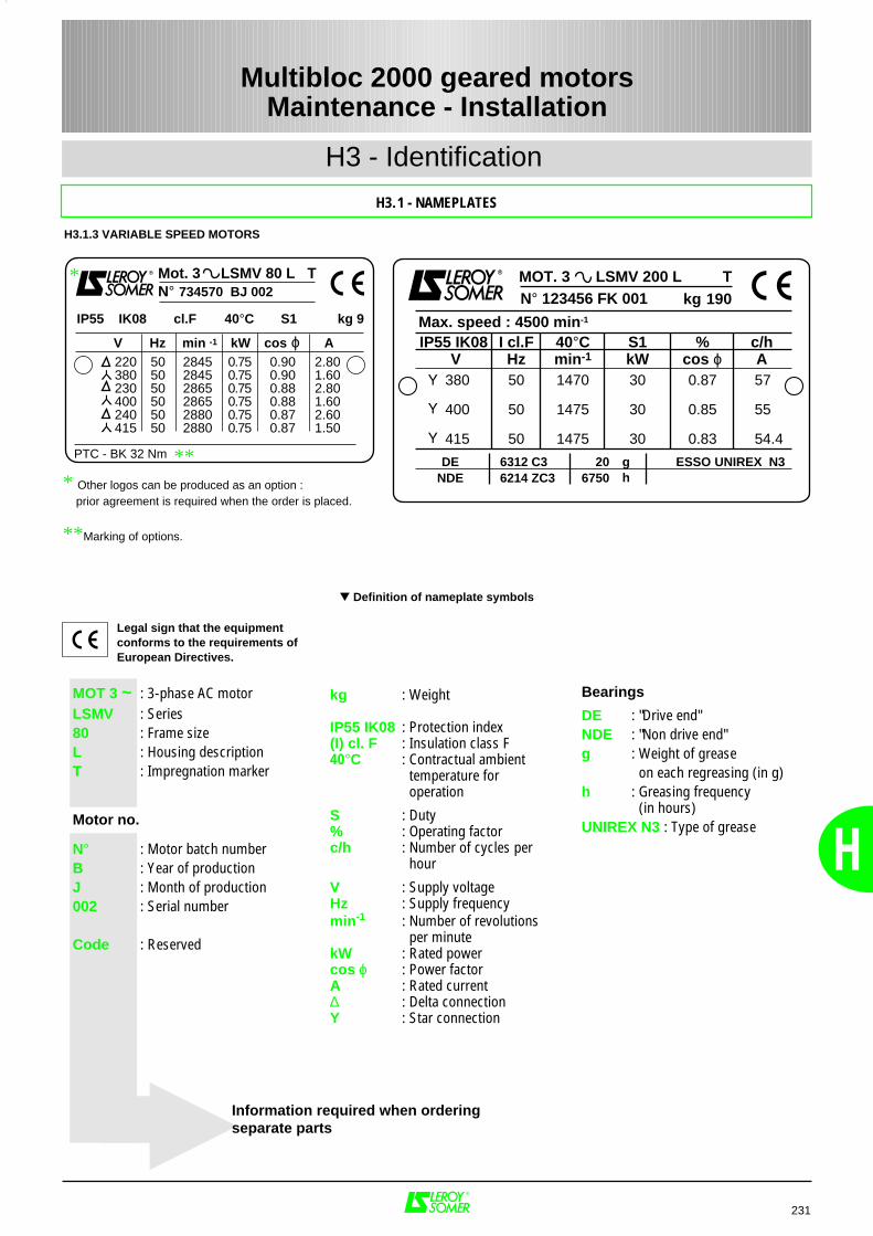
H
H3 - Identification
H3.1 - NAMEPLATES
231
Multibloc 2000 geared motorsMaintenance - Installation
MOT 3 ~ : 3-phase AC motorLSMV : Series80 : Frame sizeL : Housing descriptionT : Impregnation marker
Motor no.
N° : Motor batch numberB : Year of productionJ : Month of production002 : Serial number
Code : Reserved
kg : Weight
IP55 IK08 : Protection index(I) cl. F : Insulation class F40°C : Contractual ambient
temperature for operation
S : Duty% : Operating factorc/h : Number of cycles per
hour
V : Supply voltageHz : Supply frequencymin-1 : Number of revolutions
per minutekW : Rated powercos ϕ : Power factorA : Rated current∆ : Delta connectionY : Star connection
Definition of nameplate symbols
* Other logos can be produced as an option : prior agreement is required when the order is placed.
**Marking of options.
Information required when orderingseparate parts
N° 734570 BJ 002Mot. 3 LSMV 80 L T
IP55 IK08 cl.F 40°C S1 kg 9
V Hz min -1 kW cos ϕ A
PTC - BK 32 Nm
220380230400240415
284528452865286528802880
0.750.750.750.750.750.75
0.900.900.880.880.870.87
2.801.602.801.602.601.50
505050505050
*
Legal sign that the equipmentconforms to the requirements ofEuropean Directives.
H3.1.3 VARIABLE SPEED MOTORS
Bearings
DE : "Drive end"NDE : "Non drive end"g : Weight of grease
on each regreasing (in g)h : Greasing frequency
(in hours)UNIREX N3 : Type of grease
MOT. 3
IP55 IK08 Max. speed : 4500 min-1
I cl.F S1 %V Hz min-1 kW cos ϕ A
N° 123456 FK 001 kg
6312 C36214 ZC3
LSMV 200 L T190
40°C
380
400
415
50
50
50
1470
1475
1475
30
30
30
0.87
0.85
0.83
57 55 54.4
206750
ESSO
c/h
DENDE
gh
UNIREX N3**
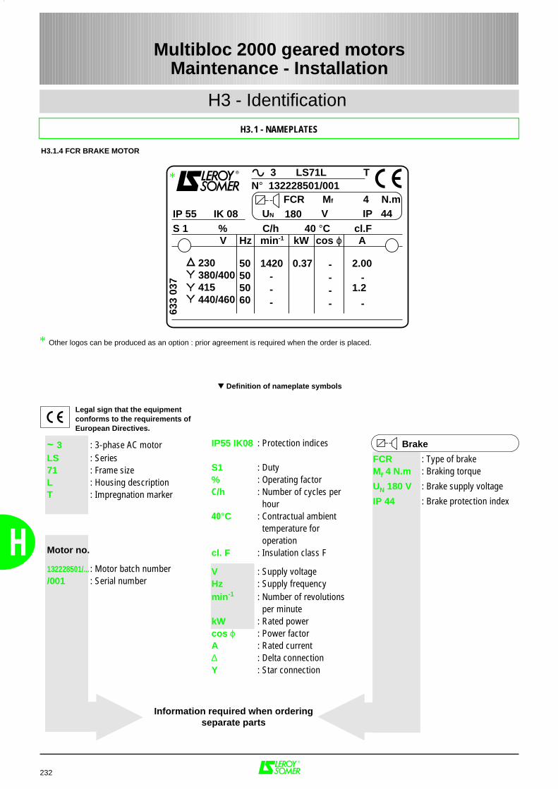
232
H
H3 - Identification
H3.1 - NAMEPLATES
Multibloc 2000 geared motorsMaintenance - Installation
~ 3 : 3-phase AC motorLS : Series71 : Frame sizeL : Housing descriptionT : Impregnation marker
Motor no.
132228501/... : Motor batch number/001 : Serial number
IP55 IK08 : Protection indices
S1 : Duty% : Operating factorC/h : Number of cycles per
hour 40°C : Contractual ambient
temperature for operation
cl. F : Insulation class F
V : Supply voltageHz : Supply frequencymin-1 : Number of revolutions
per minutekW : Rated powercos ϕ : Power factorA : Rated current∆ : Delta connectionY : Star connection
Brake
FCR : Type of brakeMf 4 N.m : Braking torque
UN 180 V : Brake supply voltage
IP 44 : Brake protection index
Definition of nameplate symbols
Information required when orderingseparate parts
H3.1.4 FCR BRAKE MOTOR
Legal sign that the equipmentconforms to the requirements ofEuropean Directives.
* Other logos can be produced as an option : prior agreement is required when the order is placed.
3 LS71L T
IP 55 IK 08S 1
V
230380/400415440/460
2.00
1.2
50505060
0.371420---
--
--
-
-
Hz min-1 kW A
633
037
% C/h 40 °C cl.Fcos ϕ
N° 132228501/001FCR 4180UN V IP 44
Mf N.m
*
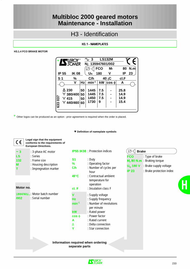
H
H3 - Identification
H3.1 - NAMEPLATES
233
Multibloc 2000 geared motorsMaintenance - Installation
~ 3 : 3-phase AC motorLS : Series132 : Frame sizeM : Housing descriptionT : Impregnation marker
Motor no.
135947601/... : Motor batch number/002 : Serial number
IP55 IK08 : Protection indices
S1 : Duty% : Operating factorC/h : Number of cycles per
hour 40°C : Contractual ambient
temperature for operation
cl. F : Insulation class F
V : Supply voltageHz : Supply frequencymin-1 : Number of revolutions
per minutekW : Rated powercos ϕ : Power factorA : Rated current∆ : Delta connectionY : Star connection
Brake
FCO : Type of brakeMf 80 N.m : Braking torque
UN 180 V : Brake supply voltage
IP 23 : Brake protection index
Definition of nameplate symbols
Information required when orderingseparate parts
H3.1.4 FCO BRAKE MOTOR
Legal sign that the equipmentconforms to the requirements ofEuropean Directives.
* Other logos can be produced as an option : prior agreement is required when the order is placed.
3 LS132M T
IP 55 IK 08S 1
V
230380/400415440/460
50505060
7.57.57.59
25.814.914.915.4
----
1445144514501730
Hz min-1 kW A
633
037
% C/h 40 ¡C cl.Fcos ϕ
N¡ 135947601/002FCO 80180UN V IP 23
Mf N.m
*
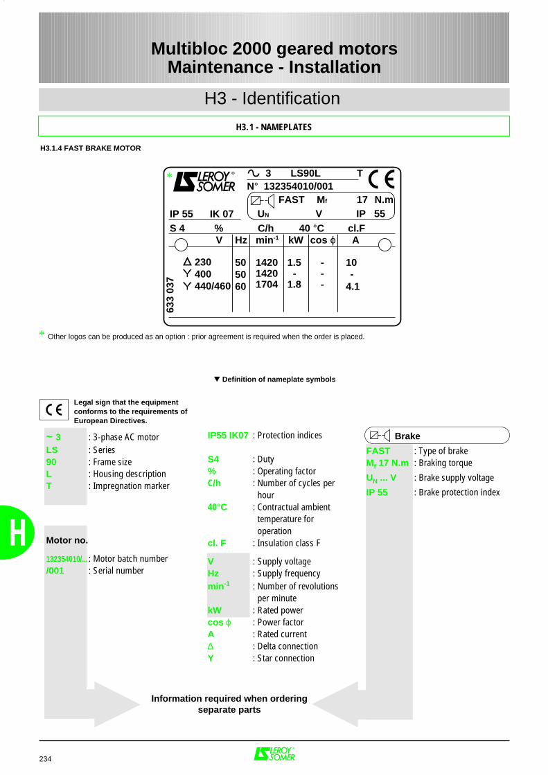
234
H
H3 - Identification
H3.1 - NAMEPLATES
Multibloc 2000 geared motorsMaintenance - Installation
~ 3 : 3-phase AC motorLS : Series90 : Frame sizeL : Housing descriptionT : Impregnation marker
Motor no.
132354010/... : Motor batch number/001 : Serial number
Brake
FAST : Type of brakeMf 17 N.m : Braking torque
UN ... V : Brake supply voltage
IP 55 : Brake protection index
Definition of nameplate symbols
Information required when orderingseparate parts
H3.1.4 FAST BRAKE MOTOR
Legal sign that the equipmentconforms to the requirements ofEuropean Directives.
* Other logos can be produced as an option : prior agreement is required when the order is placed.
3 LS90L T
IP 55 IK 07S 4
V
230400440/460
10
4.1
505060
1.5 -1.8
142014201704
---
-
Hz min-1 kW A
633
037
% C/h 40 °C cl.Fcos ϕ
N° 132354010/001FAST 17
UN V IP 55Mf N.m
*
IP55 IK07 : Protection indices
S4 : Duty% : Operating factorC/h : Number of cycles per
hour 40°C : Contractual ambient
temperature for operation
cl. F : Insulation class F
V : Supply voltageHz : Supply frequencymin-1 : Number of revolutions
per minutekW : Rated powercos ϕ : Power factorA : Rated current∆ : Delta connectionY : Star connection
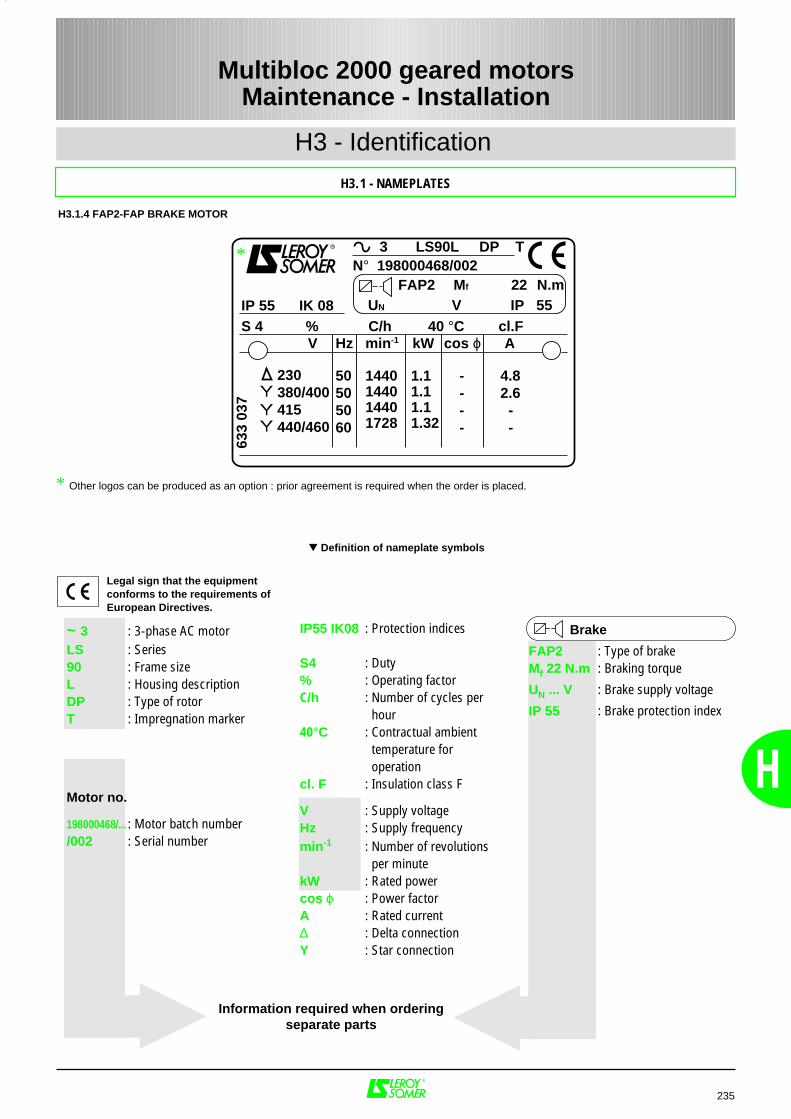
H
H3 - Identification
H3.1 - NAMEPLATES
235
Multibloc 2000 geared motorsMaintenance - Installation
~ 3 : 3-phase AC motorLS : Series90 : Frame sizeL : Housing descriptionDP : Type of rotorT : Impregnation marker
Motor no.
198000468/... : Motor batch number/002 : Serial number
Brake
FAP2 : Type of brakeMf 22 N.m : Braking torque
UN ... V : Brake supply voltage
IP 55 : Brake protection index
Definition of nameplate symbols
H3.1.4 FAP2-FAP BRAKE MOTOR
Legal sign that the equipmentconforms to the requirements ofEuropean Directives.
* Other logos can be produced as an option : prior agreement is required when the order is placed.
3 LS90L DP T
IP 55 IK 08S 4
V
230380/400415440/460
50505060
----
4.82.6 - -
1.11.11.11.32
1440144014401728
Hz min-1 kW A
633
037
% C/h 40 °C cl.Fcos ϕ
N° 198000468/002FAP2 22 UN V IP 55
Mf N.m
*
IP55 IK08 : Protection indices
S4 : Duty% : Operating factorC/h : Number of cycles per
hour 40°C : Contractual ambient
temperature for operation
cl. F : Insulation class F
V : Supply voltageHz : Supply frequencymin-1 : Number of revolutions
per minutekW : Rated powercos ϕ : Power factorA : Rated current∆ : Delta connectionY : Star connection
Information required when orderingseparate parts
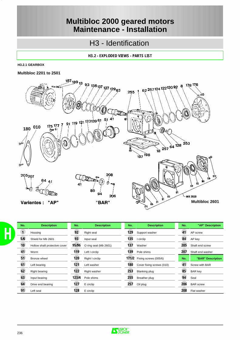
236
H
H3 - Identification
H3.2 - EXPLODED VIEWS - PARTS LIST
Multibloc 2000 geared motorsMaintenance - Installation
H3.2.1 GEARBOX
Multibloc 2201 to 2501
180 010
No. Description No. Description No. Description No. "AP" Description
1 Housing 92 Right seal 129 Support washer 41 AP screw
5/6 Shield for Mb 2601 93 Input seal 135 I circlip 84 AP key
10 Hollow shaft protective cover 95/96 O ring seal (Mb 2601) 137 Washer 205 Shaft end screw
41 Worm 119 Left I circlip 139 Pole shims 207 Shaft end washer
51 Bronze wheel 120 Right I circlip 171/2 Fixing screws (005/6) No. "BAR" Description
61 Left bearing 121 Left washer 180 Cover fixing screws (010) 41 Screw with BAR
62 Right bearing 122 Right washer 253 Blanking plug 85 BAR key
63 Input bearing 123/4 Pole shims 255 Breather plug 94 Seal
64 Drive end bearing 127 E circlip 257 Oil plug 206 BAR screw
91 Left seal 128 E circlip 208 Flat washer
Multibloc 2601

H
H3 - Identification
H3.2 - EXPLODED VIEWS - PARTS LIST
237
Multibloc 2000 geared motorsMaintenance - Installation
H3.2.1 GEARBOX
Input flange kit
No. Description Qty
13 Flange for motor 1
187 Fixing screw 4
189 Brake washers 4
209 Motor fixing screw 4
210 Washers 4
Baseplate with feet kit
No. Description Qty
18 Baseplate with feet 1
197 Fixing screw 4
198 Flat washers 4
Torque arm kit
No. Description Qty
17 Torque arm 1
195 Fixing screw 4
G or D output shaft kit
No. Description Qty
32 Output shaft 1
81 Hub key 1
82 Client key 1
199 Shaft retaining screw 1
200 Flat washer 1
201 Shaft end screw 1
203 Flat washer 1
X output shaft kit
No. Description Qty
32 Output shaft 1
81 Hub key 1
82/3 Client key 2
199 Locking screw 2
200 Locking collar 1
201/2 Shaft end screw 2
203/4 Flat washers 2
G output flange kit (except Mb 26--)
No. Description Qty
7 Left flange 1
175 Fixing screw 1
177 Brake washer 1
D output flange kit (except Mb 26--)
No. Description Qty
8 Right flange 1
176 Fixing screw 1
178 Brake washer 1
210
209
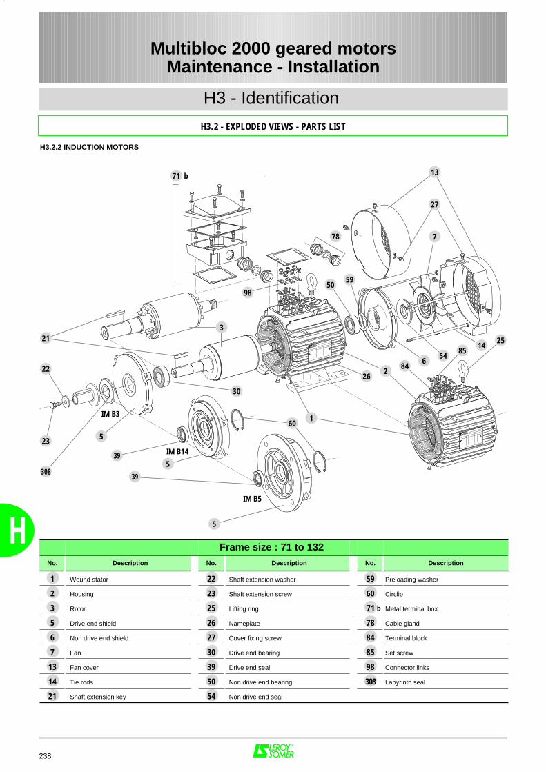
H
H3 - Identification
H3.2 - EXPLODED VIEWS - PARTS LIST
Multibloc 2000 geared motorsMaintenance - Installation
H3.2.2 INDUCTION MOTORS
71 b
78
98
213
5
22
5
5
308
23
IM B3
IM B14
IM B5
13
7
2514
8554
684
262
160
5950
27
30
39
39
Frame size : 71 to 132No. Description No. Description No. Description
1 Wound stator 22 Shaft extension washer 59 Preloading washer
2 Housing 23 Shaft extension screw 60 Circlip
3 Rotor 25 Lifting ring 71 b Metal terminal box
5 Drive end shield 26 Nameplate 78 Cable gland
6 Non drive end shield 27 Cover fixing screw 84 Terminal block
7 Fan 30 Drive end bearing 85 Set screw
13 Fan cover 39 Drive end seal 98 Connector links
14 Tie rods 50 Non drive end bearing 308 Labyrinth seal
21 Shaft extension key 54 Non drive end seal
238

348
52
6162
1033 4
1
3428
405
19
46
602
246
717
850
1115
23
H
H3 - Identification
H3.2 - EXPLODED VIEWS - PARTS LIST
Multibloc 2000 geared motorsMaintenance - Installation
H3.2.3 FCR BRAKE MOTORS
Frame size : 71 to 100No. Description No. Description No. Description
1 Stator housing 11 Armature 40 Cover screw
2 Rotor shaft 15 Lining holder fan 46 Brake power supply
3 Drive end shield 17 External circlip 48 Motor terminal block
4 Shaft end bearing 19 Keys 50 O ring seal
5 Tie rods 23 Steel cover 52 Terminal block
6 Internal circlip 24 Brake nut 60 Shaft end key
7 Brake end bearing 28 Springs 61 Shaft end screw
8 Brake shield 33 Elastic washer 62 Shaft end washer
10 Seal 34 Splined pins
239
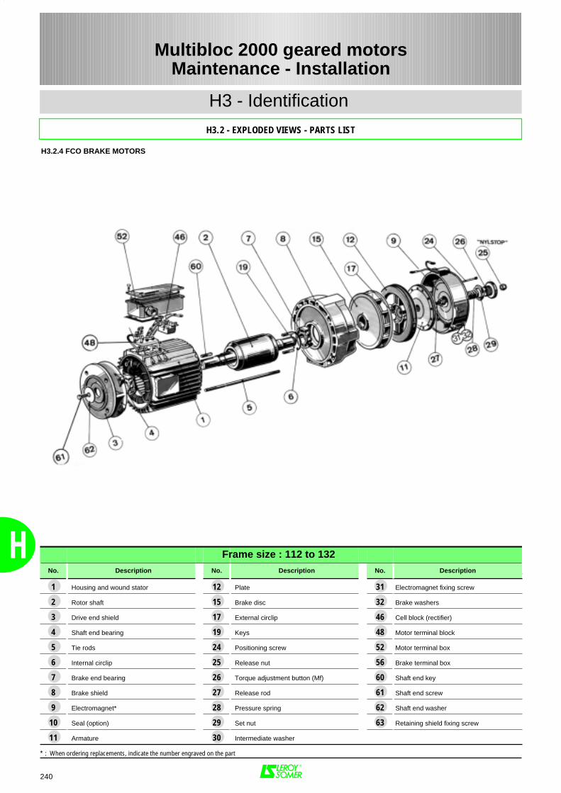
240
H
Frame size : 112 to 132No. Description No. Description No. Description
1 Housing and wound stator 12 Plate 31 Electromagnet fixing screw
2 Rotor shaft 15 Brake disc 32 Brake washers
3 Drive end shield 17 External circlip 46 Cell block (rectifier)
4 Shaft end bearing 19 Keys 48 Motor terminal block
5 Tie rods 24 Positioning screw 52 Motor terminal box
6 Internal circlip 25 Release nut 56 Brake terminal box
7 Brake end bearing 26 Torque adjustment button (Mf) 60 Shaft end key
8 Brake shield 27 Release rod 61 Shaft end screw
9 Electromagnet* 28 Pressure spring 62 Shaft end washer
10 Seal (option) 29 Set nut 63 Retaining shield fixing screw
11 Armature 30 Intermediate washer
* : When ordering replacements, indicate the number engraved on the part
H3 - Identification
H3.2 - EXPLODED VIEWS - PARTS LIST
H3.2.4 FCO BRAKE MOTORS
Multibloc 2000 geared motorsMaintenance - Installation
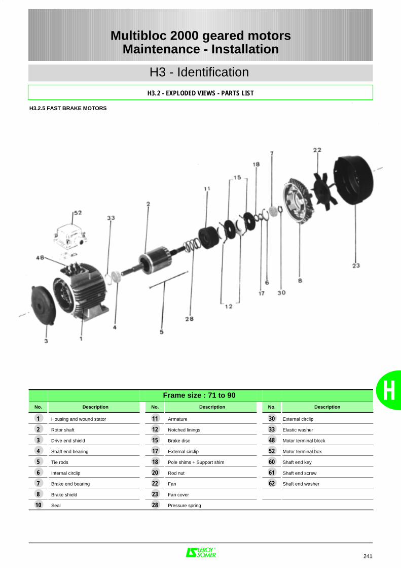
H
241
Multibloc 2000 geared motorsMaintenance - Installation
Frame size : 71 to 90No. Description No. Description No. Description
1 Housing and wound stator 11 Armature 30 External circlip
2 Rotor shaft 12 Notched linings 33 Elastic washer
3 Drive end shield 15 Brake disc 48 Motor terminal block
4 Shaft end bearing 17 External circlip 52 Motor terminal box
5 Tie rods 18 Pole shims + Support shim 60 Shaft end key
6 Internal circlip 20 Rod nut 61 Shaft end screw
7 Brake end bearing 22 Fan 62 Shaft end washer
8 Brake shield 23 Fan cover
10 Seal 28 Pressure spring
H3 - Identification
H3.2.5 FAST BRAKE MOTORS
H3.2 - EXPLODED VIEWS - PARTS LIST
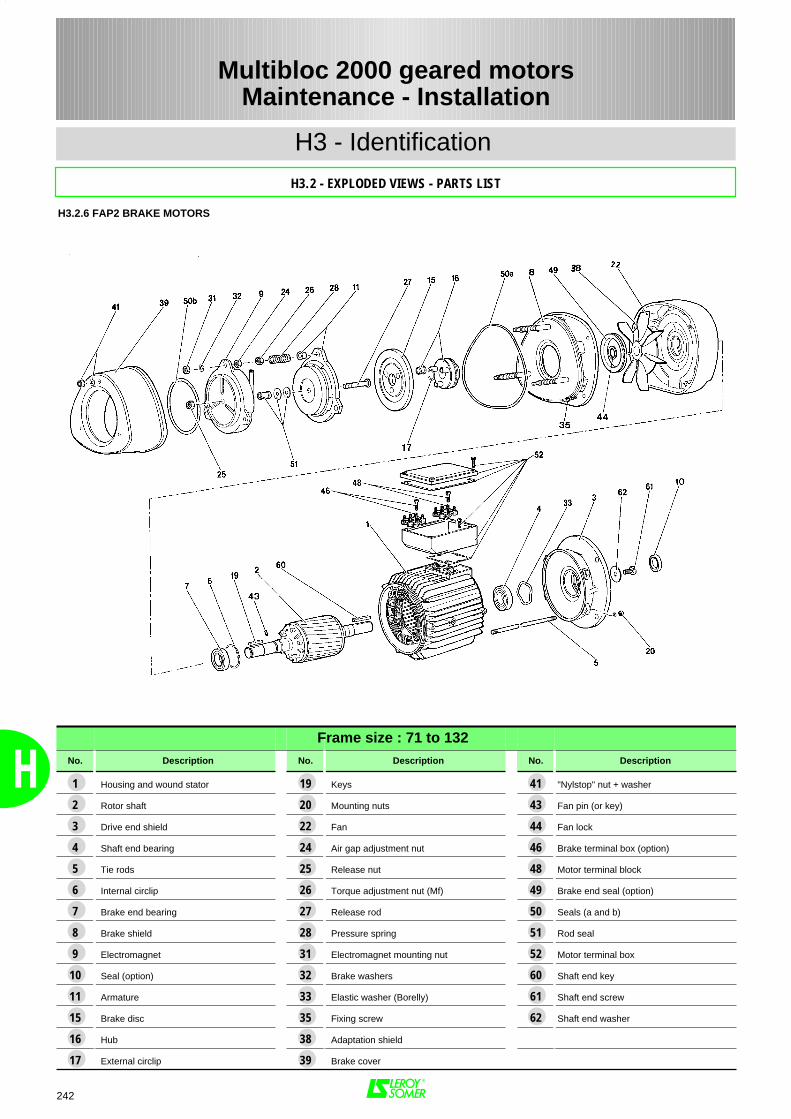
H
H3 - Identification
H3.2 - EXPLODED VIEWS - PARTS LIST
Multibloc 2000 geared motorsMaintenance - Installation
H3.2.6 FAP2 BRAKE MOTORS
Frame size : 71 to 132No. Description No. Description No. Description
1 Housing and wound stator 19 Keys 41 "Nylstop" nut + washer
2 Rotor shaft 20 Mounting nuts 43 Fan pin (or key)
3 Drive end shield 22 Fan 44 Fan lock
4 Shaft end bearing 24 Air gap adjustment nut 46 Brake terminal box (option)
5 Tie rods 25 Release nut 48 Motor terminal block
6 Internal circlip 26 Torque adjustment nut (Mf) 49 Brake end seal (option)
7 Brake end bearing 27 Release rod 50 Seals (a and b)
8 Brake shield 28 Pressure spring 51 Rod seal
9 Electromagnet 31 Electromagnet mounting nut 52 Motor terminal box
10 Seal (option) 32 Brake washers 60 Shaft end key
11 Armature 33 Elastic washer (Borelly) 61 Shaft end screw
15 Brake disc 35 Fixing screw 62 Shaft end washer
16 Hub 38 Adaptation shield
17 External circlip 39 Brake cover
242
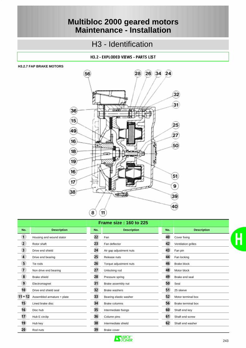
H
H3 - Identification
H3.2 - EXPLODED VIEWS - PARTS LIST
243
Multibloc 2000 geared motorsMaintenance - Installation
Frame size : 160 to 225No. Description No. Description No. Description
1 Housing and wound stator 22 Fan 40 Cover fixing
2 Rotor shaft 23 Fan deflector 42 Ventilation grilles
3 Drive end shield 24 Air gap adjustment nuts 43 Fan pin
4 Drive end bearing 25 Release nuts 44 Fan locking
5 Tie rods 26 Torque adjustment nuts 46 Brake block
7 Non drive end bearing 27 Unlocking rod 48 Motor block
8 Brake shield 28 Pressure spring 49 Brake end seal
9 Electromagnet 31 Brake assembly nut 50 Seal
10 Drive end shield seal 32 Brake washers 51 25 sleeve
11 + 12 Assembled armature + plate 33 Bearing elastic washer 52 Motor terminal box
15 Lined brake disc 34 Brake columns 56 Brake terminal box
16 Disc hub 35 Intermediate fixings 60 Shaft end key
17 Hub E circlip 36 Column pins 61 Shaft end screw
19 Hub key 38 Intermediate shield 62 Shaft end washer
20 Rod nuts 39 Brake cover
H3.2.7 FAP BRAKE MOTORS
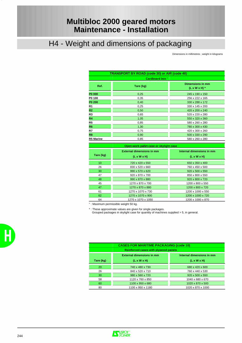
244
H
H4 - Weight and dimensions of packaging
Multibloc 2000 geared motorsMaintenance - Installation
CASES FOR MARITIME PACKAGING (code 10) Reinforced cases with plywood panels
Tare (kg)
External dimensions in mm
(L x W x H)
Internal dimensions in mm
(L x W x H)
20 740 x 480 x 730 680 x 420 x 60026 840 x 520 x 710 760 x 440 x 53030 980 x 560 x 720 920 x 500 x 55058 1120 x 760 x 850 1040 x 680 x 67060 1100 x 950 x 680 1020 x 870 x 50080 1100 x 950 x 1180 1020 x 870 x 1000
Dimensions in millimetres ; weight in kilograms
TRANSPORT BY ROAD (code 30) or AIR (code 40)
Cardboard box °
Ref. Tare (kg)Dimensions in mm
(L x W x H) *
P0 000 0,25 245 x 190 x 150P0 100 0,35 256 x 222 x 165P0 200 0,40 330 x 288 x 172R1 0,25 330 x 145 x 200R2 0,50 420 x 200 x 240R3 0,65 520 x 220 x 280R4 1,05 550 x 320 x 360R5 0,85 580 x 260 x 280R6 1,30 780 x 300 x 430R7 0,75 420 x 300 x 260R8 0,90 500 x 330 x 290R5 Marine 0,85 580 x 260 x 280
Open-work pallet case or skylight case
Tare (kg)External dimensions in mm
(L x W x H)
Internal dimensions in mm
(L x W x H)
10 720 x 420 x 550 650 x 350 x 40026 830 x 520 x 660 760 x 450 x 50030 990 x 570 x 620 920 x 500 x 55047 920 x 870 x 700 850 x 800 x 55048 990 x 870 x 880 920 x 800 x 72045 1270 x 870 x 700 1200 x 800 x 55047 1270 x 870 x 880 1200 x 800 x 72061 1270 x 1070 x 730 1200 x 1000 x 55062 1270 x 1070 x 900 1200 x 1000 x 72064 1270 x 1070 x 1050 1200 x 1000 x 870
° : Maximum permissible weight 50 kg.
* : These approximate values are given for single packages. Grouped packages in skylight case for quantity of machines supplied > 5, in general.

Notes
General sales conditions
I - APPLICATION AREAAcceptance of our tenders or the placing of any order with usimplies acceptance of the following conditions without exceptionor reservation. These conditions of sale shall prevail over allstipulations appearing on the customer's purchase order, hisgeneral conditions of purchase or any other document emanatingfrom him and / or a third party.A dispensation from these General Conditions of Sale applies tosales concerning foundry parts, which are subject to the EuropeanFoundries General Conditions of Sale, latest edition.
II - ORDERSAll orders, including those taken by our agents andrepresentatives, by whatever mode of transmission, become validonly after we have accepted them in writing.We reserve the right to modify the characteristics of our goodswithout prior warning. However, the customer reserves the possibility to specifytechnical specifications in the order. Unless such requirements have been notified in writing, thecustomer will not be able to refuse delivery of new modifiedgoods.Our company will not accept responsibility for an incorrect choiceof goods if this incorrect choice results from incomplete and / orerroneous conditions of use, or conditions that have not beenconveyed to the vendor by the customer.Unless otherwise specified, our tenders and estimates are onlyvalid for thirty days from the date of issue.When the goods have to satisfy standards, particular regulationsand / or be inspected by standards or control organisations, theprice request must be accompanied by full specifications withwhich we must comply with. This is mentioned in the estimate. Alltest and inspection fees are the customer's responsibility.
III - PRICEOur prices and price lists are shown exclusive of tax and may berevised without prior notice.Our prices are either firm for the duration specified on theestimate, or subject to revision according to a formulaaccompanying the tender which, depending on the regulations,covers a change in the cost of raw materials, products, variousservices and salaries, an index of which is published in theB.O.C.C.R.F. ("Bulletin Officiel de la Concurrence, de laConsommation et de la Répression des Fraudes").For any order of goods not found in our catalogue, requiringspecial manufacture, the invoice will include a minimum fixedsum of 600 FRF (six hundred French Francs) exclusive of tax, tocover start - up costs. Any tax due will be charged to thecustomer.All related costs, such as customs clearance and specialinspections, will be added on.Customers should remember that the French Franc (or other cur-rency) is being replaced by the Single European Currency (EURO)according to a European Community ruling. In accordance withthe general principles of monetary law, references to the FrenchFranc will then as of right be considered to refer to the Euro. Thissubstitution will be enforced on the date and in accordance withthe conditions defined by the European Community ruling.
IV - DELIVERYOur export sales are governed by the INCOTERMS published bythe International Chamber of Commerce ("I.C.C. INCOTERMS"),latest edition.Goods are despatched in accordance with the conditions indicatedon our order acknowledgement, sent out in response to any orderfor goods and / or services.Unless otherwise specified, our prices refer to goods put atcustomer's disposal in our factories, and include standardpackaging.Unless otherwise specified, goods are always transported at theconsignee's risk. Without exception, it is up to the purchaser toraise with the transporter, in the legal form and time limits, anyclaim concerning the condition or the number of packagesreceived and also to send us at the same time a copy of thisdeclaration. Failure to respect this procedure will relieve us of allresponsibility.In the case of CIF (Cost, Insurance & Freight) or CIP (Carriage &Insurance Paid to) sales, etc…, in the event of damage, ourresponsibility will only be engaged if any reservations andrequired declarations have been notified in the required timeperiod, and will not in any case exceed the indemnity sumreceived from our insurers.If the arrangements for despatch are modified, we reserve theright to invoice any additional costs arising from such changes.Packages cannot be returned.Should the delivery of goods be delayed for a reason notattributable to the vendor, goods will be stored on the vendor'spremises, at the own risk of the customer, at a charge for storageof 1% (one per cent) of the total order sum per week, beginning,without a grace period, on the day after the scheduled date ofdelivery indicated in the contract. After thirty days from this date,the vendor has the right to dispose of these goods as he wishesand arrange a new delivery date for the said goods with thecustomer. In all instances, all down payments received remain theproperty of the vendor as indemnity, without prejudice to otherclaims for damages that the vendor may wish to bring.
V - DELIVERY DATESDelivery times are stated for information only, and do not includethe month of August.Delivery dates are counted from the issue date of the orderacknowledgement from the vendor and are subject to compliancewith the provisions indicated on the order acknowledgement,notably receipt of the down payment for the order, notification ofthe issuance of an irrevocable letter of credit conforming to allvendor requirements (especially as regards the amount, currency,validity, licence, etc…) and acceptance of the terms of paymentwith any guarantees which may be required, etc…In no case does late delivery automatically entitle the customer todamages and / or penalties.Unless otherwise specified, we reserve the right to make partialdeliveries.Delivery dates are automatically suspended without formal notice,and the vendor shall have no responsibility in cases of ForceMajeure, or events beyond the control of the vendor or hissuppliers such as delays, saturation, or unavailability of the
planned transport methods, energy, raw materials etc…, seriousaccidents such as fires, explosions, strikes, lock out, oremergency measures taken by the Authorities occurring after theconclusion of the order and preventing its normal execution.Similarly, delivery dates are automatically suspended withoutformal notice in all cases of failure to perform or late payment bythe customer.
VI - TESTSAll goods manufactured by the vendor are tested before leavingthe factory in accordance with vendor's ISO 9001 certifications.Customers may attend these tests : they simply have to conveythe wish to do so in writing when the order is placed.Specific tests and acceptance tests requested by the customer,whether conducted on the customer's premises, in our factories,on-site, or by inspection organisations, must be noted on theorder and are to be paid for by the customer.Goods specially developed for a customer will have to be approvedby the latter before any delivery of mass - produced goods, notifiedby signing and returning to us the Product Approval Schedulereference Q1. T. 034.In the event of the customer's insistence on delivery withouthaving signed this form beforehand, the goods will then still beconsidered as prototypes and the customer will assume sole res-ponsibility for using it or supplying it to his own customers.
VII -TERMS OF PAYMENTAll our sales are considered as carried out and payable at theregistered office of the vendor, without exception, whatever themethod of payment, the place of conclusion of the sale and deli-very.When the customer is based in France, our invoices are payableon receipt in cash, by banker's draft, or by L.C.R. ("Lettre deChange - Relevé"), within thirty days from the end of the monthfollowing the invoice date, net and without discount.When the customer is based outside France, our invoices arepayable in cash against delivery of the dispatching documents orby irrevocable documentary credit confirmed by a first classFrench bank with all bank charges payable by the customer.Payments must be made in the currency of the invoice.In accordance with French Law N° 92.1442 dated December31,1992, non-payment of an invoice by its due date will give rise,after formal notice, to a penalty equal to one and a half times (1.5)the official rate of interest, and to late payment interest at the bankbase rate plus five per cent. If the invoice carries V.A.T. (ValueAdded Tax), this is calculated on the amount, inclusive of tax, ofthe remaining sum due and comes into force from the due date.Should steps have to be taken to recover the said amount, asurcharge of 15% (fifteen per cent) of the sum demanded will bepayable.Moreover, as a consequence of non - payment of an invoice orany term of payment, whatever the method of payment envisaged,the customer shall pay immediately for the whole of the outstan-ding amount owed to the vendor (including his subsidiaries, sisteror parent companies, whether in France or overseas) for all deliveries or services,whatever their initial due date.Notwithstanding any particular terms of payment arrangedbetween the parties concerned, the vendor reserves the right todemand :
- payment in cash, before the goods leave the factory, for allorders in the process of manufacture, in the event of aproblem with payment, or if the customer's financial situa-tion justifies it,
- a down payment for the order.Unless we are at fault, all down payments are non - returnable,without prejudice to our right to claim damages.Any payment made in advance of the fixed payment date will leadto a discount of 0.2 % (zero point two per cent) per month of theamount concerned.
VIII - COMPENSATION CLAUSEUnless prohibited by law, the vendor and the customer expresslyagree between one another to compensate their respective debtsarising from their commercial relationship, even if the conditionsdefined by law for legal compensation are not all satisfied.In applying this clause, by vendor we mean any company in theLEROY SOMER group.
IX - TRANSFER OF RISKS - TRANSFERT OF TITLETransfer of risks occurs upon the handing over of the goods,according to the delivery conditions agreed at the time ofordering.THE TRANSFER OF TITLE OF THE GOODS SOLD TO THECUSTOMER OCCURS UPON PAYMENT OF THE WHOLEPRINCIPAL SUM AND INTEREST.The provision of a document creating an obligation to pay (bankdraft or similar) does not constitute payment.So long as the price has not been paid in full, the customer isobliged to inform the vendor, within twenty - four hours, of theseizure, requisition or confiscation of goods to the benefit of athird party, and to take all safety measures to acquaint others withand respect our right of title in the event of intervention bycreditors.Failure to pay the amount due, whether total or partial, on the duedate, for whatever reason and on whatever grounds, authorisesthe vendor to demand as of right and without formal notice, thereturn of the goods, wherever they may be, at the customer'sexpense and risk.Return of the goods does not imply to cancellation of the sale.However, we reserve the option to apply the cancellation clausecontained in these General Conditions of Sale.
X - CONFIDENTIALITYThe vendor and the customer undertake to maintainconfidentiality of information of a technical, commercial or othernature, obtained during negotiations and / or the execution of anyorder.
XI - INDUSTRIAL AND INTELLECTUAL PROPERTY RIGHTSThe results, data, studies and information (whether patentable ornot), or software developed by the vendor during execution of anyorder, and delivered to the customer, are the sole property of thevendor.Apart from the instructions for use, servicing and maintenance,
reports and documents of any type that we deliver to ourcustomers remain our property and must be returned to us on re-quest, even when design fees have been charged for them, andthey shall not be communicated to third parties or used withoutthe prior written agreement of the vendor.
XII - CANCELLATION CLAUSEWe reserve the right to cancel immediately, as of right andwithout formal notice, the sale of our goods in case of non-pay-ment of any part of the price by the due date, or in case of anybreach in the contractual obligations of the customer. In this case,the goods will have to be returned to us immediately, at thecustomer's own risk and expense, subject to a penalty of 10%(ten per cent) of its value per week of delay. All payments alreadyreceived shall remain our property as indemnity, without prejudiceto our rights to claim damages.
XIII -WARRANTYThe vendor warrants the goods against any defect, arising from adefault in material or in workmanship, for twelve months startingfrom the date on which they are made available, according to theconditions defined below.The warranty for goods with special applications, or goods used24 hours a day, is automatically reduced by half.On the other hand, parts or accessories of other origin, whichbear their own brand name, are included in our warranty only tothe extent of the warranty conditions granted by the suppliers ofthese parts.The vendor's warranty will only apply insofar as the goods havebeen stored, used and maintained in accordance with the vendor'sinstructions and documentation. It cannot be invoked when thedefault results from :- failure to monitor, maintain or store the goods correctly,- normal wear and tear of goods,- intervention on or modification to the goods without the
vendor's prior authorisation in writing,- abnormal use, or use not conforming to the intended purpose, - defective installation at the customer's and / or the final user's
premises,- non-communication, by the customer, of the intended purpose
or the conditions of use of the goods,- failure to use original manufacturer's spare parts,- Force Majeure or any event beyond the control of the vendor,- etc …In all cases, the warranty is limited to the replacement or therepair of parts or goods recognised as defective by our technicaldepartments. If the repair is entrusted to a third party, it shouldonly be carried out after acceptance by the vendor of the estimatefor repair.No goods should be returned without the vendor's priorauthorisation in writing .Goods to be repaired should be sent prepaid, to the addressindicated by the vendor. If the goods have not been repairedunder warranty, the cost of dispatching it back will be invoiced tothe customer or to the end purchaser.This warranty applies to our goods in accessible form andtherefore does not cover the cost of dismantling and reinstallationof the said goods in the equipment in which they are integrated .Repair, modification, or replacement of spare parts or goods du-ring the warranty period will not extend the duration of thewarranty.The provisions of this article constitute the only obligation on thepart of the vendor concerning the warranty for the goodssupplied.
XIV -LIABILITYThe vendor will be liable for bodily injury caused by his goods orpersonnel.The repair of property damages attributable to the vendor isexpressly limited to a sum which may not exceed the amount ofthe goods found as defective.It is expressly agreed that the vendor and the customer eachwaive any right to claim for indirect, consequential and / orpunitive damages of any kind, such as loss of production, loss ofprofit, costs of withdrawal from the market or costs of recall,costs of dismantling and reinstallation of goods, loss of contracts,etc …
XV - SPARE PARTS AND ACCESSORIESSpare parts and accessories are provided on request insofar asthey are available. Related costs (carriage and any other costs)are always added to the invoice.We reserve the right to demand a minimum quantity or invoice aminimum per order.
XVI - PARTIAL INVALIDITYIf any provision of these General Conditions of Sale is held to beunenforceable for any reason, it shall be adjusted rather thanvoided, if possible, in order to achieve the intent of the parties tothe extent possible. In any event, all other provisions shall bedeemed valid and enforceable to the full extent possible.
XVII -DISPUTESTHESE GENERAL CONDITIONS OF SALE ARE GOVERNED BYFRENCH LAW.ANY DISPUTE RELATING TO OUR SALES, EVEN IN THE CASE OFMULTIPLE DEFENDANTS, SHALL BE, IN THE ABSENCE OFAMICABLE SETTLEMENT AND NOTWITHSTANDING ANY CLAUSETO THE CONTRARY, SUBJECT TO THE JURISDICTION OF THECOURTS OF ANGOULEME (France).
Re
f. :
30
90
- 4
.4 /
a -
12
.98
- 0
91
29
8 -
WORLDWIDE PRESENCE36 PRODUCTION UNITS / 470 SALES & SERVICE CENTERS WORLDWIDE
D R I V E S Y S T E M SELECTRICAL MOTORS - GEARBOXES - ELECTRONICS
European leader
in industrialdrive systems
MOTEURS LEROY-SOMER - Boulevard Marcellin Leroy - 16015 ANGOULEME cedex - FRANCEPhone +33 545 64 45 64 - Fax +33 545 64 45 04
www.leroysomer.com
ALTERNATORS - ASYNCHRONOUS & D.C. GENERATORSE N E R G Y
Réf
. 321
0 G
B -
1.3
1 / c
- 0
5.00
World leaderin alternators

MOTEURS LEROY-SOMER 16015 ANGOULÊME CEDEX - FRANCE
RCS ANGOULÊME N° B 671 820 223S.A. au capital de 131 910 700 F
http://www.leroy-somer.com


