32
MultiMaster 160 Mig / Tig / Stick Welding Package F15-678-D 07 / 2005 Instruction Manual

MultiMaster 160Mig / Tig / Stick Welding Package
F15-678-D 07 / 2005
Instruction Manual

2
BE SURE THIS INFORMATION REACHES THE OPERATOR
These INSTRUCTIONS are for experienced operators. If you are not fully familiar withthe principles of operation and safe practices for arc welding and cutting equipment,we urge you to read our booklet, "Precautions and Safe Practices for Arc Welding,Cutting, and Gouging," Form 52-529. Do NOT permit untrained persons to install,operate, or maintain this equipment. Do NOT attempt to install or operate thisequipment until you have read and fully understand these instructions. If you do notfully understand these instructions, contact your supplier for further information. Besure to read the Safety Precautions before installing or operating this equipment.
Copies of this manual can be obtained by any of the following;
Contacting your local ESAB supplier.
Downloading a copy from the ESAB web site atwww.esabna.com
Sending a written request to
ESAB WELDING & CUTTING PRODUCTSATTN: LITERATURE DEPT.
411 S EBENEZER ROADFLORENCE SC 29501
USER RESPONSIBILITYThis equipment will perform in conformity with the description thereof contained in this manual andaccompanying labels and/or inserts when installed, operated, maintained and repaired in accordancewith the instructions provided. This equipment must be checked periodically. Malfunctioning orpoorly maintained equipment should not be used. Parts that are broken, missing, worn, distortedor contaminated should be replaced immediately. Should such repair or replacement becomenecessary, the manufacturer recommends that a telephone or written request for service advicebe made to the Authorized Distributor from whom it was purchased.
This equipment or any of its parts should not be altered without the prior written approval of themanufacturer. The user of this equipment shall have the sole responsibility for any malfunctionwhich results from improper use, faulty maintenance, damage, improper repair or alteration byanyone other than the manufacturer or a service facility designated by the manufacturer.

3
SECTION NO. PAGE NO.
SECTION 1.0 - SAFETY PRECAUTIONS ......................................................................................................................................... 3
SECTION 2.0 - INTRODUCTION ....................................................................................................................................................... 9
SECTION 3.0 - INSTALLATION ...................................................................................................................................................... 133.1 LOCATION .......................................................................................................................................................... 133.2 ELECTRICAL INPUT CONNECTIONS ............................................................................................................. 133.2.1 INPUT ELECTRICAL REQUIREMENTS ........................................................................................................... 133.2.2 INPUT PLUG ...................................................................................................................................................... 133.3 SECONDARY OUTPUT CONNECTIONS ......................................................................................................... 133.4 WIRE FEEDER MECHANISM ........................................................................................................................... 133.4.1 DRIVE ROLLS .................................................................................................................................................... 133.4.2 WELD WIRE SPOOL INSTALLATION .............................................................................................................. 133.4.3 THREADING THE WELDING WIRE ................................................................................................................. 143.4.4 SPOOL BRAKE DRAG ADJUSTMENT ............................................................................................................. 143.5 CONNECTION OF SHIELDING GAS SUPPLY ................................................................................................ 143.5.1 R-33-FM-580 REGULATOR (OPTIONAL) ........................................................................................................ 143.5.2 TO REGULATE FLOW ....................................................................................................................................... 15
SECTION 4.0 - OPERATION ............................................................................................................................................................ 164.1 STANDARD CONTROLS ................................................................................................................................... 164.1.1 POWER ON/OFF SWITCH ................................................................................................................................ 164.2.2 TEMP LAMP ....................................................................................................................................................... 164.1.3 PROCESS SELECTOR SWITCH ...................................................................................................................... 164.1.4 SECONDARY WELDING CONNECTIONS ....................................................................................................... 164.1.5 WIRE FEED SPEED CONTROL ....................................................................................................................... 164.1.5 VOLTAGE CONTROL ........................................................................................................................................ 164.1.7 CURRENT CONTROL ....................................................................................................................................... 164.1.8 HOT START ....................................................................................................................................................... 164.2 OPERATING PROCEDURES ............................................................................................................................ 184.2.1 MIG WELDING SET-UP ..................................................................................................................................... 184.2.2 TIG WELDING SET-UP ..................................................................................................................................... 194.2.3 STICK WELDING SET-UP ................................................................................................................................. 20
SECTION 5.0 - MAINTENANCE ...................................................................................................................................................... 215.1 MAINTENANCE AND SERVICE ....................................................................................................................... 215.2 INSPECTION AND SERVICE ............................................................................................................................ 215.2.1 POWER SOURCE .............................................................................................................................................. 215.2.1.1 RECTIFIERS AND TRANSISTORS .................................................................................................................. 215.2.1.2 FAN MOTOR ...................................................................................................................................................... 215.2.1.3 TRANSFORMER ................................................................................................................................................ 215.2.1.4 OVER-TEMPERATURE PROTECTION ............................................................................................................ 215.2.2 WIRE FEEDER ................................................................................................................................................... 21
SECTION 6.0 - REPLACEMENT PARTS ........................................................................................................................................ 236.1 REPLACEMENT PARTS ................................................................................................................................... 236.2 GENERAL ........................................................................................................................................................... 236.3 ORDERING ......................................................................................................................................................... 23
Table of Contents

4
Table of Contents

5
WARNING: These Safety Precautions are foryour protection. They summarize precaution-ary information from the references listed inAdditional Safety Information section. Before
performing any installation or operating procedures, besure to read and follow the safety precautions listed belowas well as all other manuals, material safety data sheets,labels, etc. Failure to observe Safety Precautions can resultin injury or death.
PROTECT YOURSELF AND OTHERS --Some welding, cutting, and gougingprocesses are noisy and require earprotection. The arc, like the sun, emitsultraviolet (UV) and other radiation and
can injure skin and eyes. Hot metal can cause burns.Training in the proper use of the processes and equip-ment is essential to prevent accidents. Therefore:
1. Always wear safety glasses with side shields in any workarea, even if welding helmets, face shields, and gogglesare also required.
2. Use a face shield fitted with the correct filter and coverplates to protect your eyes, face, neck, and ears fromsparks and rays of the arc when operating or observingoperations. Warn bystanders not to watch the arc andnot to expose themselves to the rays of the electric-arcor hot metal.
3. Wear flameproof gauntlet type gloves, heavy long-sleeveshirt, cuffless trousers, high-topped shoes, and a weld-ing helmet or cap for hair protection, to protect againstarc rays and hot sparks or hot metal. A flameproof apronmay also be desirable as protection against radiatedheat and sparks.
4. Hot sparks or metal can lodge in rolled up sleeves,trouser cuffs, or pockets. Sleeves and collars should bekept buttoned, and open pockets eliminated from thefront of clothing
5. Protect other personnel from arc rays and hot sparkswith a suitable non-flammable partition or curtains.
6. Use goggles over safety glasses when chipping slag orgrinding. Chipped slag may be hot and can fly far.Bystanders should also wear goggles over safety glasses.
FIRES AND EXPLOSIONS -- Heat fromflames and arcs can start fires. Hot slagor sparks can also cause fires and ex-plosions. Therefore:
1. Remove all combustible materials well away from thework area or cover the materials with a protective non-flammable covering. Combustible materials include wood,cloth, sawdust, liquid and gas fuels, solvents, paints andcoatings, paper, etc.
2. Hot sparks or hot metal can fall through cracks orcrevices in floors or wall openings and cause a hiddensmoldering fire or fires on the floor below. Make certainthat such openings are protected from hot sparks andmetal.
3. Do not weld, cut or perform other hot work until theworkpiece has been completely cleaned so that thereare no substances on the workpiece which might pro-duce flammable or toxic vapors. Do not do hot work onclosed containers. They may explode.
4. Have fire extinguishing equipment handy for instant use,such as a garden hose, water pail, sand bucket, orportable fire extinguisher. Be sure you are trained in itsuse.
SAFETY PRECAUTIONS
5. Do not use equipment beyond its ratings. For example,overloaded welding cable can overheat and create a firehazard.
6. After completing operations, inspect the work area tomake certain there are no hot sparks or hot metal whichcould cause a later fire. Use fire watchers when neces-sary.
7. For additional information, refer to NFPA Standard 51B,"Fire Prevention in Use of Cutting and Welding Pro-cesses", available from the National Fire Protection Asso-ciation, Batterymarch Park, Quincy, MA 02269.
ELECTRICAL SHOCK -- Contact with liveelectrical parts and ground can causesevere injury or death. DO NOT use ACwelding current in damp areas, if move-ment is confined, or if there is danger offalling.
1. Be sure the power source frame (chassis) is connectedto the ground system of the input power.
2. Connect the workpiece to a good electrical ground.3. Connect the work cable to the workpiece. A poor or
missing connection can expose you or others to a fatalshock.
4. Use well-maintained equipment. Replace worn or dam-aged cables.
5. Keep everything dry, including clothing, work area, cables,torch/electrode holder, and power source.
6. Make sure that all parts of your body are insulated fromwork and from ground.
7. Do not stand directly on metal or the earth while workingin tight quarters or a damp area; stand on dry boards oran insulating platform and wear rubber-soled shoes.
8. Put on dry, hole-free gloves before turning on the power.9. Turn off the power before removing your gloves.
10. Refer to ANSI/ASC Standard Z49.1 (listed on next page)for specific grounding recommendations. Do not mis-take the work lead for a ground cable.
ELECTRIC AND MAGNETIC FIELDS —May be dangerous. Electric current flow-ing through any conductor causes lo-calized Electric and Magnetic Fields(EMF). Welding and cutting current cre-ates EMF around welding cables andwelding machines. Therefore:
1. Welders having pacemakers should consult their physi-cian before welding. EMF may interfere with some pace-makers.
2. Exposure to EMF may have other health effects which areunknown.
3. Welders should use the following procedures to minimizeexposure to EMF:A. Route the electrode and work cables together. Secure
them with tape when possible.B. Never coil the torch or work cable around your body.C. Do not place your body between the torch and work
cables. Route cables on the same side of your body.D. Connect the work cable to the workpiece as close as
possible to the area being welded.E. Keep welding power source and cables as far away
from your body as possible.
6
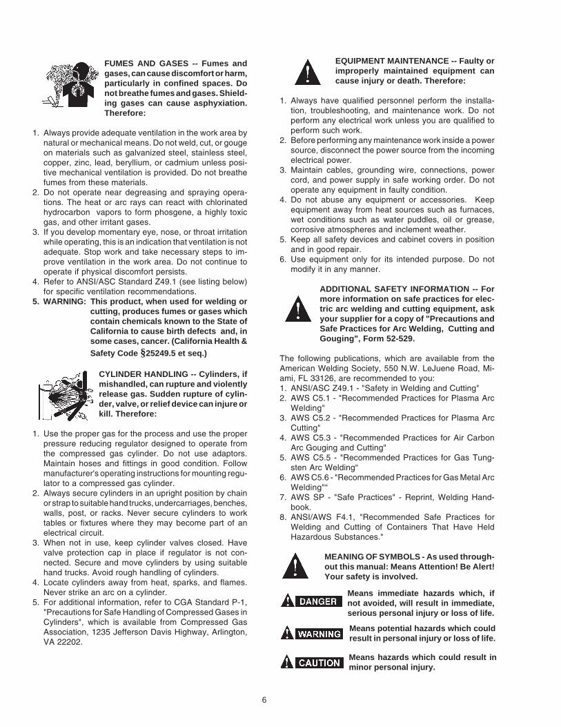
FUMES AND GASES -- Fumes andgases, can cause discomfort or harm,particularly in confined spaces. Donot breathe fumes and gases. Shield-ing gases can cause asphyxiation.Therefore:
1. Always provide adequate ventilation in the work area bynatural or mechanical means. Do not weld, cut, or gougeon materials such as galvanized steel, stainless steel,copper, zinc, lead, beryllium, or cadmium unless posi-tive mechanical ventilation is provided. Do not breathefumes from these materials.
2. Do not operate near degreasing and spraying opera-tions. The heat or arc rays can react with chlorinatedhydrocarbon vapors to form phosgene, a highly toxicgas, and other irritant gases.
3. If you develop momentary eye, nose, or throat irritationwhile operating, this is an indication that ventilation is notadequate. Stop work and take necessary steps to im-prove ventilation in the work area. Do not continue tooperate if physical discomfort persists.
4. Refer to ANSI/ASC Standard Z49.1 (see listing below)for specific ventilation recommendations.
5. WARNING: This product, when used for welding orcutting, produces fumes or gases whichcontain chemicals known to the State ofCalifornia to cause birth defects and, insome cases, cancer. (California Health &Safety Code §25249.5 et seq.)
CYLINDER HANDLING -- Cylinders, ifmishandled, can rupture and violentlyrelease gas. Sudden rupture of cylin-der, valve, or relief device can injure orkill. Therefore:
1. Use the proper gas for the process and use the properpressure reducing regulator designed to operate fromthe compressed gas cylinder. Do not use adaptors.Maintain hoses and fittings in good condition. Followmanufacturer's operating instructions for mounting regu-lator to a compressed gas cylinder.
2. Always secure cylinders in an upright position by chainor strap to suitable hand trucks, undercarriages, benches,walls, post, or racks. Never secure cylinders to worktables or fixtures where they may become part of anelectrical circuit.
3. When not in use, keep cylinder valves closed. Havevalve protection cap in place if regulator is not con-nected. Secure and move cylinders by using suitablehand trucks. Avoid rough handling of cylinders.
4. Locate cylinders away from heat, sparks, and flames.Never strike an arc on a cylinder.
5. For additional information, refer to CGA Standard P-1,"Precautions for Safe Handling of Compressed Gases inCylinders", which is available from Compressed GasAssociation, 1235 Jefferson Davis Highway, Arlington,VA 22202.
EQUIPMENT MAINTENANCE -- Faulty orimproperly maintained equipment cancause injury or death. Therefore:
1. Always have qualified personnel perform the installa-tion, troubleshooting, and maintenance work. Do notperform any electrical work unless you are qualified toperform such work.
2. Before performing any maintenance work inside a powersource, disconnect the power source from the incomingelectrical power.
3. Maintain cables, grounding wire, connections, powercord, and power supply in safe working order. Do notoperate any equipment in faulty condition.
4. Do not abuse any equipment or accessories. Keepequipment away from heat sources such as furnaces,wet conditions such as water puddles, oil or grease,corrosive atmospheres and inclement weather.
5. Keep all safety devices and cabinet covers in positionand in good repair.
6. Use equipment only for its intended purpose. Do notmodify it in any manner.
ADDITIONAL SAFETY INFORMATION -- Formore information on safe practices for elec-tric arc welding and cutting equipment, askyour supplier for a copy of "Precautions andSafe Practices for Arc Welding, Cutting andGouging", Form 52-529.
The following publications, which are available from theAmerican Welding Society, 550 N.W. LeJuene Road, Mi-ami, FL 33126, are recommended to you:1. ANSI/ASC Z49.1 - "Safety in Welding and Cutting"2. AWS C5.1 - "Recommended Practices for Plasma Arc
Welding"3. AWS C5.2 - "Recommended Practices for Plasma Arc
Cutting"4. AWS C5.3 - "Recommended Practices for Air Carbon
Arc Gouging and Cutting"5. AWS C5.5 - "Recommended Practices for Gas Tung-
sten Arc Welding“6. AWS C5.6 - "Recommended Practices for Gas Metal Arc
Welding"“7. AWS SP - "Safe Practices" - Reprint, Welding Hand-
book.8. ANSI/AWS F4.1, "Recommended Safe Practices for
Welding and Cutting of Containers That Have HeldHazardous Substances."
MEANING OF SYMBOLS - As used through-out this manual: Means Attention! Be Alert!Your safety is involved.
Means immediate hazards which, ifnot avoided, will result in immediate,serious personal injury or loss of life.
Means potential hazards which couldresult in personal injury or loss of life.
Means hazards which could result inminor personal injury.

7
a. Éloigner suffisamment tous les matériaux combus-tibles du secteur où l’on exécute des soudures ou descoupes à l’arc, à moins de les recouvrir complètementd’une bâche non-inflammable. Ce type de matériauxcomprend notamment le bois, les vêtements, la sciure,l’essence, le kérosène, les peintures, les solvants, legaz naturel, l’acétylène, le propane et autres sub-stances combustibles semblables.
b. Les étincelles ou les projections de métal incandes-cent peuvent tomber dans des fissures du plancher oudans des ouvertures des murs et y déclencher uneignition lente cachée. Veiller à protéger ces ouverturesdes étincelles et des projections de métal.
c. N’exécutez pas de soudures, de coupes, d’opérationsde gougeage ou autres travaux à chaud à la surfacede barils, bidons, réservoirs ou autres contenantsusagés, avant de les avoir nettoyés de toute trace desubstance susceptible de produire des vapeursinflammables ou toxiques.
d. En vue d’assurer la prévention des incendies, ilconvient de disposer d’un matériel d’extinction prêt àservir immédiatement, tel qu’un tuyau d’arrosage, unseau à eau, un seau de sable ou un extincteur portatif.
e. Une fois le travail à l’arc terminé, inspectez le secteurde façon à vous assurer qu’aucune étincelle ou projec-tion de métal incandescent ne risque de provoquerultérieurement un feu.
3. CHOC ÉLECTRIQUE-- Le gougeage à l’arc et à l’arcau plasma exige l’emploi de tensions à viderelativement importantes; or, celles-ci risquent decauser des dommages corporels graves et mêmemortels en cas d’utilisation inadéquate. La gravité duchoc électrique reçu dépend du chemin suivi par lecourant à travers le corps humain et de son intensité.
a. Ne laissez jamais de surfaces métalliques sous ten-sion venir au contact direct de la peau ou devêtements humides. Veillez à porter des gants biensecs.
b. Si vous devez effectuer un travail sur une surfacemétallique ou dans un secteur humide, veillez à assu-rer votre isolation corporelle en portant des gants secset des chaussures à semelles de caoutchouc et envous tenant sur une planche ou une plate-formesèche.
c. Mettez toujours à la terre le poste de soudage/coupageen le reliant par un câble à une bonne prise de terre.
d. N’utilisez jamais de câbles usés ou endommagés. Nesurchargez jamais le câble. Utilisez toujours unéquipement correctement entretenu.
e. Mettez l’équipement hors tension lorsqu’il n’est pas enservice. une mise à la masse accidentelle peut en effetprovoquer une surchauffe de l’équipement et un dan-ger d’incendie. Ne pas enrouler ou passer le câbleautour d’une partie quelconque du corps.
f. Vérifiez si le câble de masse est bien relié à la pièce enun point aussi proche que possible de la zone detravail. Le branchement des câbles de masse àl’ossature du bâtiment ou en un point éloigné de lazone de travail augmente en effet le risque de pas-sage d’un courant de sortie par des chaînes de
PRÉCAUTIONS DE SÉCURITÉAVERTISSEMENT: Ces règles de sécurité ont pour objetd’ assurer votre protection. Veillez à lire et à observer lesprécautions énoncées ci-dessous avant de monter l’équipement ou de commercer à l’utiliser. Tout défautd’observation de ces précautions risque d’entraîner desblessures graves ou mortelles.1. PROTECTION INDIVIDUELLE-- Les brûlures de la
peau et des yeux dues au rayonnement de l’arcélectrique ou du métal incandescent, lors du soudageau plasma ou à l’électrode ou lors du gougeage àl’arc, peuvent s’avérer plus graves que cellesrésultant d’une exposition prolongée au soleil. Aussiconvient-il d’observer les précautions suivantes:
a. Portez un écran facial adéquat muni des plaquesprotectrices et des verres filtrants appropriés afin devous protéger les yeux, le visage, le cou et les oreillesdes étincelles et du rayonnement de l’arc électriquelorsque vous effectuez des soudures ou des coupesou lorsque vous en observez l’exécution.
AVERTISSEZ les personnes se trouvant à proximitéde façon à ce qu’elles ne regardent pas l’arc et à cequ’elles ne s’exposent pas à son rayonnement, ni àcelui du métal incandescent.
b. Portez des gants ignifugés à crispins, une tuniqueépaisse à manches longues, des pantalons sansrebord, des chaussures à embout d’acier et uncasque de soudage ou une calotte de protection, afind’éviter d’exposer la peau au rayonnement de l’arcélectrique ou du métal incandescent. ll est égalementsouhaitable d’utiliser un tablier ininflammable defaçon à se protéger des étincelles et du rayonnementthermique.
c. Les étincelles ou les projections de métal incandes-cent risquent de se loger dans des manchesretroussées, des bords relevés de pantalons ou dansdes poches. Aussi convient-il de garder boutonnés lecol et les manches et de porter des vêtements sanspoches à l’avant.
d. Protégez des étincelles et du rayonnement de l’arcélectrique les autres personnes travaillant à proximitéà l’aide d’un écran ininflammable adéquat.
e. Ne jamais omettre de porter des lunettes de sécuritélorsque vous vous trouvez dans un secteur où l’oneffectue des opérations de soudage ou de coupage àl’arc. Utilisez des lunettes de sécurité à écrans ouverres latéraux pour piquer ou meûler le laitier. Lespiquetures incandescentes de laitier peuvent êtreprojetées à des distances considérables. Lespersonnes se trouvant à proximité doivent égalementporter des lunettes de protection.
f. Le gougeage à l’arc et le soudage à l’arc au plasmaproduisent un niveau de bruit extrêmement élevé (de100 à 114 dB) et exigent par conséquent l’emploi dedispositifs appropriés de protection auditive.
2. PRÉVENTION DES INCENDES-- Les projections delaitier incandescent ou d’étincelles peuventprovoquer de graves incendies au contact dematériaux combustibles solides, liquides ou gazeux.Aussi faut-il observer les précautions suivantes:

8
levage, des câbles de grue ou divers cheminsélectriques.
g. Empêchez l’apparition de toute humidité, notammentsur vos vêtements, à la surface de l’emplacement detravail, des câbles, du porte-électrode et du poste desoudage/coupage. Réparez immédiatement toutefuite d’eau.
4. VENTILATION-- La respiration prolongée des fuméesrésultant des opérations de soudage/coupage, àl’intérieur, d’un local clos, peut provoquer des mal-aises et des dommages corporels. Aussi convient-ild’observer les précautions suivantes:
a. Assurez en permanence une aération adéquate del’emplacement de travail en maintenant une ventila-tion naturelle ou à l’aide de moyens mécaniques.N’effectuez jamais de travaux de soudage ou decoupage sur des matériaux de zinc, de plomb, deberyllium ou de cadmium en l’absence de moyensmécaniques de ventilation capables d’empêcherl’inhalation des fumées dégagées par ces matériaux.
b. N’effectuez jamais de travaux de soudage ou decoupage à proximité de vapeurs d’hydrocarburechloré résultant d’opérations voisines de dégraissageou de pulvérisation. La chaleur dégagée ou lerayonnement de l’arc peut déclencher la formation dephosgène -- gaz particulièrement toxique -- et d’autresgaz irritants, à partir des vapeurs de solvant.
c. Une irritation momentanée des yeux, du nez ou de lagorge constatée au cours de l’utilisation del’équipement dénote un défaut de ventilation. Arrêtez-vous de travailler afin de prendre les mesures néces-saires à l’amélioration de la ventilation. Ne poursuivezpas l’opération entreprise si le malaise persiste.
d. Certaines commandes comportent des canalisationsoù circule de l’hydrogène. L’armoire de commande estmunie d’un ventilateur destiné à empêcher la forma-tion de poches d’hydrogène, lesquelles présentent undanger d’explosion; ce ventilateur ne fonctionne quesi l’interrupteur correspondant du panneau avant setrouve placé en position ON (Marche). Veillez àmanœuvrer cette commande en vérifiant si lecouvercle est bien en place, de façon à assurerl’efficacité de la ventilation ainsi réalisée. Ne jamaisdébrancher le ventilateur.
e. Les fumées produites par l’opération de soudage oude coupage peuvent s’avérer toxiques. Aussi est-ilnécessaire de disposer en permanence d’un dispositifadéquat de ventilation de type aspirant, afin d’élimi-ner du voisinage de l’opérateur tout dégagement defumée visible.
f. Consultez les recommandations particulières enmatière de ventilation indiquées à l’alinéa 6 de lanorme Z49.1 de l’AWS.
5. ENTRETIEN DE L’ÉQUIPEMENT-- Un équipemententretenu de façon défectueuse ou inadéquate risquenon seulement de réaliser un travail de mauvaise
qualité mais, chose plus grave encore, d’entraîner desdommages corporels graves, voire mortels endéclenchant des incendies ou des chocs électriques.Observez par conséquent les précautions suivantes:
a. Efforcez-vous de toujours confier à un personnel qua-lifié l’installation, le dépannage et l’entretien du postede soudage et de coupage. N’effectuez aucuneréparation électrique sur l’équipement à moins d’êtrequa-lifié à cet effet.
b. Ne procédez jamais à une tâche d’entretienquelconque à l’intérieur du poste de soudage/coupage, avant d’avoir débranché l’alimentationélectrique.
c. Maintenez en bon état de fonctionnement les câbles,le câble de masse, les branchements, le cordond’alimentation et le poste de soudage/coupage.N’utilisez jamais le poste ou l’équipement s’il présenteune défectuosité quelconque.
d. Prenez soin du poste de soudage et de coupage et deséquipements accessoires. Gardez-les à l’écart dessources de charleur, notamment des fours, del’humidité, des flaques d’eau maintenez-les à l’abri destraces d’huile ou de graisse, des atmosphères corro-sives et des intempéries.
e. Laissez en place tous les dispositifs de sécurité et tousles panneaux de l’armoire de commande en veillant àles garder en bon état.
f. Utilisez le poste de soudage/coupage conformément àson usage prévu et n’effectuez aucune modification.
6. INFORMATIONS COMPLÉMENTAIRES RELATIVESÀ LA SÉCURITÉ--
Pour obtenir des informations complémentaires sur lesrègles de sécurité à observer pour le montage etl’utilisation d’équipements de soudage et de coupageélectriques et sur les méthodes de travailrecommandées, demandez un exemplaire du livret N°52529 “Precautions and Safe Practices for Arc Weld-ing, Cutting and Gouging” publié par ESAB. Nousconseillons également de consulter les publicationssui-vantes, tenues à votre disposition par l’AmericanWelding Society, 550 N.W. LeJuene Road, Miami, FL32126:
a. “Safety in Welding and Cutting” AWS Z49.1b. “Recommended Safe Practices for Gas-Shielded Arc
Welding “AWS A6. 1.c. “Safe Practices for Welding and Cutting Containers
That Have Held Combustibles” AWS-A6.0.d. “Recommended Safe Practices for Plasma Arc Cutting”
AWS-A6. 3.e. “Recommended Safe Practices for Plasma Arc Weld-
ing” AWS-C5. 1.f. “Recommended Safe Practices for Air Carbon Arc
Gouging and Cutting” AWS-C5. 3.g. “Code For Safety in Welding and Cutting”
CSA-Standard W117. 2.

9
SECTION 2 INTRODUCTION
InputPrimary Input Voltage ....................................................................... 208 Vac, 1-Phase......................................................................................................... 230 Vac, 1-Phase
Primary Input Current ....................................................................... 30 Amp @ 208 Vac......................................................................................................... 27 Amp @ 230 Vac
Frequency ........................................................................................ 50/60HzPower Factor .................................................................................... 0.81Nominal Power - MIG ....................................................................... 5.4KVANominal Power - electrode ............................................................... 6.3KVANominal Power - TIG ........................................................................ 3.9KVAProtective Fuses ............................................................................... 20A time-lagDegree of Protection ........................................................................ IP 21Insulation Class ................................................................................ FOperating Temperature .................................................................... From 14°F to 104°F (-10°C to +40°C)
OutputDuty Cycle - MIG .............................................................................. 160A - 60%Duty Cycle - electrode ...................................................................... 160A - 60%Duty Cycle - TIG DC ......................................................................... 160A - 70%OCV.................................................................................................. 75VArc Voltage - MIG ............................................................................. 13.0 - 23.0Arc Voltage - electrode ..................................................................... 20.2 - 26.4Arc Voltage - TIG .............................................................................. 10.2 - 16.4Regulation range - MIG .................................................................... 20 - 160Regulation range - electrode ............................................................ 5 - 160ARegulation range - TIG ..................................................................... 10 - 160AHot Start ........................................................................................... AdjustableArc Force .......................................................................................... Automatic (built-in)Antisticking ....................................................................................... Automatic (built-in)Ignition - electrode ............................................................................ ScratchIgnition - TIG ..................................................................................... Lift-arcWire Spool ........................................................................................ 5/15/20kg (12/33/44 lb)Wire .................................................................................................. Metal, fluxed core (no gas)
DimensionsLength .............................................................................................. 22.4” (560mm)Width ................................................................................................ 9.2” (230mm)Height ............................................................................................... 15.4” (385mm)Weight .............................................................................................. 33lbs(15Kg )(net)
Ordering Information
MultiMaster® 160 cvcc Multi-Process PackagesMultimaster packages listed below include power source with built-in wire feeder with .030/.035 drive roll, primary input cable, weldinggun, work cable with clamp, FREE #10 spool of .030 Coreshield®
15 wire, and #1 sample 6013LV 1/8” stick electrodes.
Multimaster® 160 w/13-ft. MXL 200 ........................................... 0558002772Multimaster® 160 w/13-ft. MXL 200 & Stinger ........................... 0558002773Multimaster® 160 w/13-ft. MXL 200 & Stinger/HW-17/Reg ............ 0558002774
Table 1 Multimaster 160 Specifications

10
Optional EquipmentMultiMaster® 160 Options & AccessoriesReplacement Work Cable - 10 ft. ........................................................ 0369857881Electrode Holder and Work Cable Kit - 25mm 10 ft. ............................ 0349501078Replacement AF-1 Electrode Holder only ................................................... 882F25HW-17V 25 ft. w/25mm Connector ...................................................... 0558002690Kit, Accessory HW-17 ................................................................................. 999126R-33 FM-580 Reg/Flowmeter ........................................................................ 21557Primary Extension Cord (25 ft.) 50 amp ........................................................ 37833Feedroll .023”/.030” V for Hard Wire .............................................................. 21155Feedroll .030”/.030” Serrated for Core Wire .................................................. 21160MXL 200cc 10 ft. (3m) x .023”-.030” ................................................... 0700200002MXL 200cc 13 ft. (4m) x .023”-.030” ................................................... 0700200003Gas Nozzle - Standard 7/16” (12mm) ................................................. 0700200054Gas Nozzle - Straight 5/8” (16mm) ..................................................... 0700200057Gas Nozzle - Conical 3/8” (9.5mm) .................................................... 0700200060Contact Tip, .023” (0.6mm) .................................................................. 0700200063Contact Tip, .030” (0.8mm) .................................................................. 0700200064Contact Tip, .035” (0.9mm) .................................................................. 0700200065Contact Tip, .040” (1.0mm) .................................................................. 0700200066MXL 200 Tip Adapter - Short ............................................................... 0700200072MXL 200 Tip Adapter - Long ................................................................ 0700200067MXL 200 Nozzle Spring ....................................................................... 0700200078Steel Liner .023”-.030” (0.6-0.8mm) x 13ft. (4m) ................................. 0700200086Steel Liner .035”-.045” (0.9-1.2mm) x 13ft. (4m) ................................. 0700200088Teflon Liner .023”-.030” (0.6-0.8mm) x 13ft. (4m) ............................... 0700200090Teflon Liner .035”-.045” (0.9-1.2mm) x 13ft. (4m) ............................... 0700200092Gas Meter ...................................................................................................... 19043
25mm Connectors - quick-acting twist lock connectorsfor attaching output power cables or torches to power source:Gas / Power Adapter for Heliarc HW-9 and 17 Torches ............................... 37158Male Quick Connector ................................................................................... 37159
SECTION 2 INTRODUCTION
11
2.1 GENERALThis manual has been prepared for experienced weld-ers. Do NOT permit untrained persons to install, operateor maintain this equipment. Do NOT attempt to install oroperate this equipment until you have read and fully un-derstand these instructions.
This manual is intended for use in familiarizing personnelwith the design and operation of this equipment. All infor-mation presented here should be read carefully beforeinstalling and using this equipment.
2.2 RECEIVING-HANDLINGUpon receipt of this equipment, clean all packing materialfrom around the unit and immediately inspect for any dam-age that may have occurred during shipment. Any claimsfor loss or damage occurring in transit must be filed withthe carrier. The carrier will furnish a copy of the bill oflading and the freight bill on request, if the need to file adamage claim arises.
When requesting information regarding this equipment,make sure that you include product name, part number,and serial number.
2.3 SAFETYThe safety section at the front of this manual should beread completely before attempting to install and operatethis equipment. Both equipment and personnel hazardsare reduced if proper safety precautions are taken. If youare unsure of yourself in any situation, ask your supervi-sor or other experienced personnel for help.
SECTION 2 INTRODUCTION
and tubular cored wires. This unit is suitable for carbonsteel and stainless steel. It provides a power source withbuilt in wire feeder.
2.4.2 PACKAGE CONTENTS (Standard Accessories)Each Multimaster 160 package includes:• Power source with built-in wire feeder.• Gun Master 250 Mig Gun with .035" accessories.• Dual groove feed rolls for .030/.035” core wire• 10' work cable and clamp.• 8' primary cable with plug.• Mig Welding Handbook and set-up guide.• Tig Welding Handbook• Coreshield 15—.035 x 10# Spool• LV 6013 Stick Electrodes 1#
2.4.4 POWER SOURCEThe power source is a DC output designed for single phaseprimary connections. An output controlled fan providesproper cooling during normal welding operations If the dutycycle is exceeded, the unit will automatically shut downand the Over Temperature light will illuminate. Once theunit reaches a safe operating temperature, the unit willautomatically reset and welding can resume..
2.4.5 WIRE FEEDERThe wire feeder is built into the power source cabinet.Cooling air is not drawn through the wire feeder compart-ment or electronic controls reducing exposure to dirt anddust which improves product performance and reliability.
The wire feeder pushes wire at speeds from 65 to 650ipm (inches per minute).
2.4.6 CONTROLSThe Multimaster 160 can be used to weld solid and fluxcored wires. The operator selects the process desired ona three position switch located on the front panel. A de-tailed description of the power source controls is includedin Section 4 (Operation) of this manual.
2.4.8 MXL 200 MIG GUNThis air-cooled welding gun is supplied complete and readyto weld .030 in. flux cored wire. Other wire sizes and typescan be used. Refer to Section 2, for other wire size andalloy accessories.
Means immediate hazards which, if notavoided, will result in immediate, seriouspersonal injury or loss of life.
Means potential hazards which couldresult in personal injury or loss of life.
Means hazards which could result in mi-nor personal injury.
2.4 DESCRIPTIONThe Multimaster 160 is a DC welding system designedfor Mig (GMAW), Tig (GTAW) or Stick (SMAW) welding.In the Mig mode this unit is capable of operating with shortarc or spray arc transfer and handles both solid wires
12
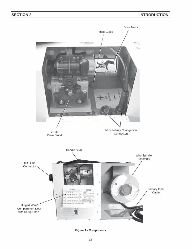
Figure 1 - Components
SECTION 2 INTRODUCTION
Handle Strap
Hinged Wire Compartment Door
with Setup Chart
Wire SpindleAssembly
2 RollDrive Stand
MIG Polarity ChangeoverConnectors
Drive Motor
MIG GunConnector
Primary InputCable
Inlet Guide

13
3.0 INSTALLATION
3.1 LOCATION
Several factors should be considered when locating theunit for use. Adequate ventilation is necessary to providecooling, and the amount of dirt and dust to which themachine is exposed should be minimized. There shouldbe at least 18 inches of unrestricted space between themachine’s side and rear panels and the nearest obstruc-tion to provide freedom of air movement through the powersource.
Installing or placing any type of filtering device will restrictthe volume of intake air, thus subjecting the internal com-ponents to overheating. Warranty is void if any type offiltering device is used.
3.2 ELECTRICAL INPUT CONNECTIONS
A cord with plug attached is provided. Connect the plug toa properly grounded and protected (fuse or circuit breaker)230 Vac receptacle.
Before making any connections to the power supplyoutput terminals, make sure that all primary inputpower to the machine is deenergized (off) and thatinput power cable is unplugged.
3.2.1 INPUT ELECTRICAL REQUIREMENTSThe primary input voltage requirements are shown on thepower source nameplate. The power source is designedto be operated from 208/230 vac single phase 50/60 Hz.
SECTION 3 INSTALLATION
Figure 2 - Dimensions
22.4”560 mm
9.2”230 mm
15.4”385 mm
3.2.2 INPUT PLUGThe input power cord is provided with an attachment plug. Theplug will mate with a 250 volt, 50 Amp receptacle con-forming to NEMA 6-50R configuration. The receptaclemust be wired to a separately fused disconnect or circuitbreaker by a qualified electrician.
3.3 SECONDARY OUTPUT CONNECTIONS
The Multimaster 160 Welding System has an internal Po-larity changeover for the MIG Process located under theHinge Cover. Front panel output receptacles make for easypolarity changeover for TIG and STICK. See Sections4.2.1, 4.2.2 and 4.2.3 for specific details on Connect Leadsand Cables for your application. Also the MIG torch con-nections are external allowing easy changes.
3.4 WIRE FEEDER MECHANISM
3.4.1 DRIVE ROLLS (Figure 5 and 7)When viewing the drive roll, the stamped designation facingyou is the groove in use. The drive roll has two grooves:the small groove feeds .030 in. diameter wire, the largegroove feeds .035 in. wire. The groove nearest the gearmotor feeds the wire. If the required groove is not cor-rectly positioned, perform the following:
A. Release the pressure drive roll lever.B. Remove the screw holding the drive roll.C. Reverse the drive roll on the drive roll shaft.D. Replace the screw and tighten.E. Secure the pressure drive roll assembly.
3.4.2 TORCH INSTALLATIONA Mig torch with a euro-type adapter is supplied as standardequipment with the Multimaster 160 System. This torchconnects directly to the fitting mounted on the front panel.Line up matching holes, push on and tighten locking collar.As shipped from the factory, the euro or common connec-tor type torches are set-up for D.C.R.P. welding polarity(See Figure #3).
Figure 3 - Torch Connection

14
Figure 5 - Threading the Wire
3.4.3 WELDING WIRE SPOOL INSTALLATION
As with any work area, make sure safety glasses withside shields are worn when handling or changing wireor clipping wire off at the spool or at the end of thetorch. Hold onto the wire coming off the spool withone hand before clipping. Serious eye injury can re-sult due to the resilience of the wire which can quicklyunravel, or a cut wire end which may shoot across theroom.
Install a spool of welding wire on the spindle as follows:
A. Unscrew red plastic nut.B. Place wire spool on the spindle to rotate counter-
clockwise (wire feeds off of the top) as wire is un-wound; spindle brake pin must engage hole in spool.
C. Spool spacer is used when running a 10# Spool ofWire. Place wire on first, followed by spacer, and thenplastic nut.
D. Replace the locking nut.
3.4.4 THREADING WELDING WIREA. Turn off power switch.B. Release pressure drive roll assembly. Check that
proper wire diameter grooves are in the inner position.
Before threading welding wire, make sure chisel pointand burrs have been removed from wire end to pre-vent wire from jamming in gun or liner.
SECTION 3 INSTALLATION
Figure 4 - Wire Feeder Mechanism
C. Feed the wire from the spool through the inlet guide,across the drive roll grooves into the outlet guide andcc connection tube.
To ensure proper wire feeding, it is important that thewire be kept clean and that the drive rolls be periodicallycleaned of any chips or scale that might be carried intothe gun liner.
D. Lower pressure roll assembly and secure. Turn thepower “on” and feed wire through to gun tip using thegun trigger to start wire feeding.
When the power switch is on, and gun trigger is de-pressed, the electrode wire becomes electrically hot,and the wire drive rolls will rotate.
3.4.5 SPOOL BRAKE DRAG ADJUSTMENTSpool brake disc friction should provide enough drag tokeep the wire spool from spinning freely after wire feedstops. If adjustment is required, turn the adjusting screwinside the spindle housing clockwise to increase drag orcounterclockwise to decrease it. Drag should be justenough to limit wire overrun.
Threading the wire throughthe inlet guide
Pressure Release Lever
Feed Roll Release Screw
Inlet Guide
3.5 CONNECTION OF SHIELDING GAS SUPPLY
3.5.1 R-33-FM-580 Regulator (OPTIONAL)The R-33-FM-580 regulator is an adjustable regulator de-signed for use with Argon, Helium, and C-25 (75% Ar-gon/25% CO2) gas service. Table 2 table provides therecommended flow ranges for the R-33-FM-580 regula-tor.

15
WireSpool
Locking Nut
Argon 10-50 cfhHelium 150-230 cfhC-25 10-50 cfh
Table 2 - Typical Flow Rates
Cylinders must be secured in a safe fashion. For additionalinformation, refer to CGA Standard P-1, “Precautions forSafe Handling of Compressed Gases in Cylinders”.
SECTION 3 INSTALLATION
Unscrew the cylinder cap.
Do not clamp regulator cap in a vise or grip it with apair of pliers. Distortion of cap can jam the internalparts and cause excessively high delivery pressureas well as weaken the threaded joint to the regulatorbody. This may cause the cap to fly off and possiblyinjure personnel in area.
D. Open the cylinder valve slightly, for an instant, to blowout any dust or dirt that may have collected in the valveoutlet. BE SURE to keep your face away from thevalve outlet to protect your eyes.
E. Attach the regulator to the cylinder valve. Align theregulator so that the flowmeter is vertical and thentighten the connection nut with a 1-1/8 in. open endor adjustable wrench. To prevent damaging the O-ring seals and plastic tube, do not use the flowmetertube as a 'handle' when attaching the regulator.
Cylinder Valve
CylinderPressureGauge
OutletConnection
Figure 7
Figure 6 - Wire Spool Assembly
F. Close the flow control valve on the flowmeter.G. Attach the gas hose from the rear of the Multimaster
160 to the regulator outlet connection.
Never stand directly in front of or behind the regula-tor when opening the cylinder valve. Always standto one side.
H. Open the cylinder valve SLOWLY a fraction of a turn.This will prevent damage to the gauge and criticalcomponents in the regulator. When the gauge needlestops moving, then open the cylinder valve fully.
I. Using a leak test solution, such as P/N 998771 (8 oz.ctr) or soapy water, test for leakage around the cylin-der valve stem, the regulator inlet connection, andthe hose connections at the regulator. Correct anyleaks before starting work.
3.5.2 TO REGULATE FLOWFlow is controlled by adjusting the flowmeter valve untildesired flow is indicated by the ball float in the flowmetertube. Always take the reading across the TOP of the ball.

16
4.1.4 SECONDARY WELDING CONNECTIONSThe secondary output welding terminals, POS (+) andNEG (-) are located in the lower front panel. Refer to Po-larity Setup.
4.1.5 WIRE FEED SPEED CONTROL (Figure 8)The wire feed speed control potentiometer located in theupper left-hand side, allows wire feed speed adjustmentsbetween 65 and 650 inches per minute (IPM).
4.1.6 VOLTAGE CONTROL (Figure 9)The arc voltage is controlled with this knob when the Pro-cess selector switch is in the MIG position. Refer to WeldChart and set the recommended setting.
4.1.7 CURRENT CONTROL (Figure 8)
The welding current is controlled with this knob when theProcess selector switch is in the STICK OR TIG position.Refer to Weld Chart and set the recommended setting.
4.1.8 HOT START (Figure 8)
The Hot Start feature is used to control the amount ofstarting current in the Stick welding mode. This helpsensure positive arc strikes for difficult to start electrodesand also allows for softer starts on thin material.
SECTION 3 INSTALLATION
4.0 OPERATION
4.1 STANDARD CONTROLS
4.1.1 POWER ON/OFF SWITCH & LAMPThe main power switch is located on the front panel in thelower right-hand corner. This switch energizes the maintransformer, control circuitry and illuminates the switchface.
4.1.2 TEMP LAMP (Figure 8)The TEMP lamp illuminates if an over temperaturecondition occurs within the Multimaster 160. This conditionmay be caused by excessive duty cycle or over-currentconditions. When an over temperature condition occurs,the welding output is turned off and the unit must beallowed to cool. The machine will automatically reset whenthe temperature falls to a safe level.
4.1.3 PROCESS SELECTOR SWITCH (Figure 8)The three position process selector switch is located inthe upper left-hand corner of the control panel. The pro-cess selector switch provides the visual indication of whichprocess (STICK, TIG, MIG) has been selected.

17
SECTION 4 OPERATION
Weld ProcessSwitch
Current Set
Wire FeedSpeed Trim
IPM
Figure 8 - Control Panel
Positive OutputConnection Negative Output
Connection
TemperatureLamp
Voltage Set
MainPowerSwitch
Wire Feed Speed
Hot Start
Figure 9 - Front Panel

18
4.2 OPERATING PROCEDURES
Comply with all ventilation, fire and other safety re-quirements for arc welding as established in theSAFETY Section at the front of this manual.
4.2.1 MIG WELDING SET-UP
When the PROCESS switch is placed in the MIG positionthe Multimaster 160 is set to turn ”ON” when the Mig Guntrigger is depressed.
Step 1. Choose the weld parameters based of the wirealloy, diameter, material thickness and shieldinggas from Table 3 - MIG PARAMETERS CHART.Set the polarity as shown in Filgure 10 for theprocess being used.
Step 2. Place the WELD PROCESS (1) switch in the MIG(FAR RIGHT) position.
Step 3. Turn the Wire Speed Knob (2) to the desiredspeed.
Step 4. Turn the VOLTAGE (3) knob to the desired arcvoltage.
Step 5. Pull the gun trigger and start welding. Trim thewire speed and volts as needed for the desiredarc characteristics.
Figure 10 - MIG Polarity Connection
SECTION 4 OPERATION
Figure 11 - Front Control Panel -MIG (GMAW) Process Setup
Table 3 - MIG PARAMETERS CHART
Option: If using one, set the shielding gas flow rate to 35cfh by pulling the gun trigger and turning the ad-justment knob on the R33-FM 580 Flowmeter.
MIG - DCEP (Electrode Positive)
Work Cableand Clamp
PolarityChangeoverConnector
MIG GunConnector
1
2
3

19
4.2.2 TIG WELDING SETUP
When the PROCESS switch is placed in the TIG position,the Multimaster 160 turns “ON” the weld contactor so thatpower is immediately available to the output connection. TheTouch TIG starting system is then enabled.
When the WELD PROCESS switch is moved to the TIGor STICK position, electrode becomes electrically“HOT”. Do not allow the electrode to contact groundpotential until you are ready to make a weld.
Step 1. Determine the weld parameters based on the metalthickness in Table 4 or use the ESAB TIG WeldingHandbook for suggested welding parameters.
Figure 12 - TIG Polarity Connection
SECTION 4 OPERATION
Figure 13-Front Control Panel -TIG (GTAW) Process SetupTable 4 - TIG PARAMETERS CHART
Step 2. Be sure to set the polarity to DCEN (ElectrodeNegative) by placing the Heliarc Torch in theNegative connection terminal on the front ofthe power source as shown in Figure 12.
Step 3. Place the WELD PROCESS (1) switch in theTIG (center) position.
Step 4. Turn the CURRENT (4) knob to the desiredweld current.
Step 5. Set the shielding gas flow rate to 20 cfh byopening the manual gas valve on the Heliarctorch and adjusting the control knob on the R-33-FM-580 flowmeter.
Step 6. Touch the tungsten electrode to the workpiecemomentarily to establish the welding arc. Trimthe current as desired by turning theCURRENT(4) knob.
NOTE: The Wirespeed (2) and Volume (3) knobs have no effect in theTIG mode.
Work Cableand Clamp
TIG - DCEN (Electrode Negative)
2
1
3
4
20
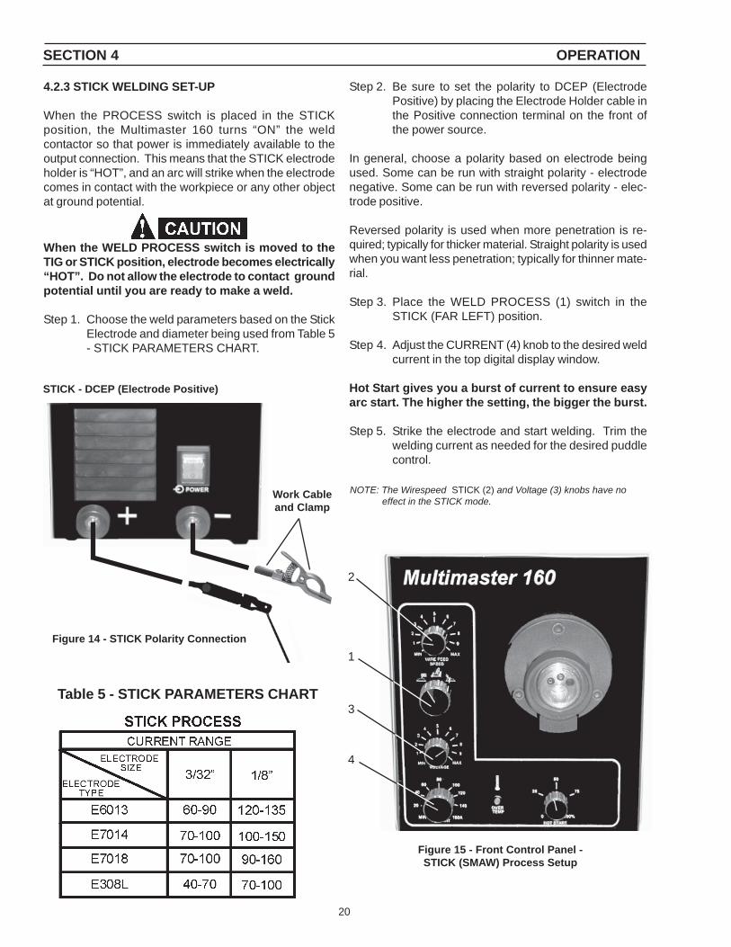
4.2.3 STICK WELDING SET-UP
When the PROCESS switch is placed in the STICKposition, the Multimaster 160 turns “ON” the weldcontactor so that power is immediately available to theoutput connection. This means that the STICK electrodeholder is “HOT”, and an arc will strike when the electrodecomes in contact with the workpiece or any other objectat ground potential.
When the WELD PROCESS switch is moved to theTIG or STICK position, electrode becomes electrically“HOT”. Do not allow the electrode to contact groundpotential until you are ready to make a weld.
Step 1. Choose the weld parameters based on the StickElectrode and diameter being used from Table 5- STICK PARAMETERS CHART.
SECTION 4 OPERATION
Figure 15 - Front Control Panel -STICK (SMAW) Process Setup
Table 5 - STICK PARAMETERS CHART
Step 2. Be sure to set the polarity to DCEP (ElectrodePositive) by placing the Electrode Holder cable inthe Positive connection terminal on the front ofthe power source.
In general, choose a polarity based on electrode beingused. Some can be run with straight polarity - electrodenegative. Some can be run with reversed polarity - elec-trode positive.
Reversed polarity is used when more penetration is re-quired; typically for thicker material. Straight polarity is usedwhen you want less penetration; typically for thinner mate-rial.
Step 3. Place the WELD PROCESS (1) switch in theSTICK (FAR LEFT) position.
Step 4. Adjust the CURRENT (4) knob to the desired weldcurrent in the top digital display window.
Hot Start gives you a burst of current to ensure easyarc start. The higher the setting, the bigger the burst.
Step 5. Strike the electrode and start welding. Trim thewelding current as needed for the desired puddlecontrol.
NOTE: The Wirespeed STICK (2) and Voltage (3) knobs have noeffect in the STICK mode.
STICK - DCEP (Electrode Positive)
Work Cableand Clamp
2
1
3
4
Figure 14 - STICK Polarity Connection
21
SECTION 5 MAINTENANCE
5.0 MAINTENANCE
5.1 MAINTENANCE AND SERVICE
Be sure that the branch circuit or main disconnectswitch and Multimaster power switch are off or elec-trical input fuses are removed before attempting anyinspection or work inside the power source. Placingthe power switch on the power source in the off po-sition does not remove all power from inside theequipment.
Inspection, troubleshooting and repair of this equip-ment may ordinarily be undertaken by a competentindividual having at least general experience in themaintenance and repair of semi-conductor electronicequipment. Maintenance or repair should not be un-dertaken by anyone not having such qualifications.
Shut OFF shielding gas supply at source.
5.2 INSPECTION AND SERVICE
Keep equipment in clean and safe operating conditionfree of oil, grease, and (in electrical part) liquid and me-tallic particles which can cause short circuits.
Regularly check cylinder valves, regulators, hoses, andgas connections for leaks with soap solution or leak testsolution (P/N 998771).
Check for and tighten loose hardware including electricalconnections. Loose power connections overheat duringwelding.
Immediately replace all worn or damaged power cablesand connectors. Check for frayed and cracked insulation,particularly in areas where conductors enter equipment.
The electrode wire and all metal parts in contact with itare electrically energized while welding. Inspect theseparts periodically for defective insulation and other elec-trical hazards.
If uninsulated cable and parts are not replaced, anarc caused by a bare cable or part touching agrounded surface may damage unprotected eyes orstart a fire. Body contact with a bare cable, connec-tor, or uncovered conductor can cause a fatal shock.
Keep power cables dry, free of oil and grease, and pro-tected at all times from damage by hot metal and sparks.Clean dirt and metal particles from drive roll grooveweekly; replace roll if badly worn.
5.2.1 POWER SOURCE
5.2.1.1 RECTIFIERS AND TRANSISTORSIt is recommended that the internal components becleaned occasionally by blowing them out with low pres-sure compressed air. This cleaning operation is neces-sary so that maximum cooling will be accomplished bythe air stream. This should be done periodically, depend-ing upon the location of the unit and the amount of dustand dirt in the atmosphere.
The hermetically sealed diodes and transistors are spe-cially designed for welding machine use and will not ageor deteriorate with use. The rectifiers are mounted on heatsinks. A periodic cleaning of dust and dirt from these isnecessary to insure cooling of the rectifiers. Should anyrectifier need replacement, it can be quickly removed fromthe heat sink.
5.2.1.2 FAN MOTORAll models are equipped with an exhaust fan and rely onforced draft for adequate cooling for high duty cycles andoverloads.
Do not use filters on this unit as they would restrictthe volume of intake air. Output ratings on this unitare based on an unobstructed supply of cooling airdrawn over its internal components. Warranty is voidif any type of filtering device is used.
5.2.1.3 TRANSFORMEROccasional blowing out of the dust and dirt from aroundthe transformer is recommended. This should be doneperiodically depending upon the location of the unit andthe amount of dust and dirt in the atmosphere. The PowerSource case cover should be removed and a clean, drylow pressure air stream should be used for this cleaningoperation.
5.2.1.4 OVER-TEMPERATURE PROTECTIONThe Power Source is protected from high internal tem-peratures by thermal switches. When the Power Sourceis operated under high current applications for long peri-ods, the thermal switches may reach a high temperaturecausing it to de-energize the contactor. These thermalswitches will reset automatically after the heat sink ortransformer windings have cooled to a safe level. Whilede-energized, the contactor can not be operated. But, ifthe gun trigger is depressed, the unit will still feed wireand the solenoid will operate.
5.2.2 WIRE FEEDERAs soft wire is fed, the drive rolls may pick up metal fromthe wire surface. Accumulation on the rolls may score thewire with resulting unwanted friction and improper feed-ing.
Inspect the rolls regularly and clean them with a fine-wirepower brush. Avoid roughening, or removing the hard-ness of groove surfaces in grooved rolls. Any rougheningmay score the wire, just as the accumulation being re-moved may do.
22
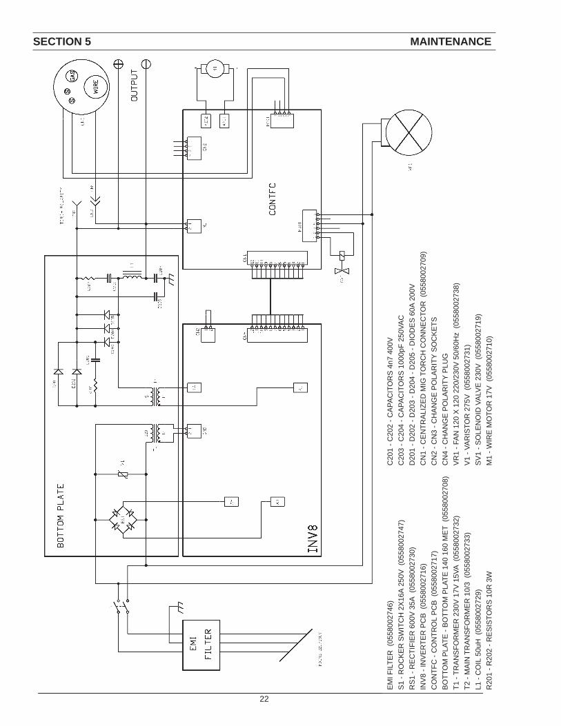
SECTION 5 MAINTENANCE
EM
I FIL
TER
(05
5800
2746
)S
1 - R
OC
KE
R S
WIT
CH
2X
16A
250
V (
0558
0027
47)
RS
1 - R
EC
TIFI
ER
600
V 3
5A (
0558
0027
30)
INV
8 - I
NV
ER
TER
PC
B (
0558
0027
16)
CO
NTF
C -
CO
NTR
OL
PC
B (
0558
0027
17)
BO
TTO
M P
LATE
- B
OTT
OM
PLA
TE 1
40 1
60 M
ET
(055
8002
708)
T1 -
TRA
NS
FOR
ME
R 2
30V
17V
15V
A (0
5580
0273
2)T2
- M
AIN
TR
AN
SFO
RM
ER
10/
3 (0
5580
0273
3)L1
- C
OIL
50u
H (
0558
0027
29)
R20
1 - R
202
- RE
SIS
TOR
S 1
0R 3
W
C20
1 - C
202
- CA
PAC
ITO
RS
4n7
400
VC
203
- C20
4 - C
APA
CIT
OR
S 1
000p
F 25
0VA
CD
201
- D20
2 - D
203
- D20
4 - D
205
- DIO
DE
S 6
0A 2
00V
CN
1 - C
EN
TRA
LIZE
D M
IG T
OR
CH
CO
NN
EC
TOR
(05
5800
2709
)C
N2
- CN
3 - C
HA
NG
E P
OLA
RIT
Y S
OC
KE
TSC
N4
- CH
AN
GE
PO
LAR
ITY
PLU
GV
R1
- FA
N 1
20 X
120
220
/230
V 5
0/60
Hz
(055
8002
738)
V1
- VA
RIS
TOR
275
V (
0558
0027
31)
SV
1 - S
OLE
NO
ID V
ALV
E 2
30V
(05
5800
2719
)M
1 - W
IRE
MO
TOR
17V
(05
5800
2710
)

23
6.1 General
Replacement Parts are illustrated on the following figures.When ordering replacement parts, order by part numberand part name, as illustrated on the figure.
Always provide the series or serial number of the unit onwhich the parts will be used. The serial number is stampedon the unit nameplate.
6.2 Ordering
Replacement parts may be ordered from your ESAB dis-tributor or from:
ESAB Welding & Cutting ProductsAttn: Customer Service Dept.PO Box 100545, Ebenezer RoadFlorence, SC, 29501-0545
Be sure to indicate any special shipping instructions whenordering replacement parts.
Refer to the Communications Guide on back cover ofthis manual for a list of customer service phone num-bers.
SECTION 6 REPLACEMENT PARTS

24
12
11 10
146
51637
4
15
813
1817
19
20
Feed
Mot
orSECTION 6 REPLACEMENT PARTS

25
Item No. Part No. Description Cct. Ref.
1 0558002626 Multimaster 1602 0558002704 Lid with Handle/Strap (Not Shown)3 0558002735 Knob Ø 25mm4 0558002736 Knob Ø 22mm5 0558002707 Connector Dinse 25 +, -6 0558002708 Bottom Plate7 0558002709 MIG EURO Connector8 0558002710 Wire Feeder Assembly
Includes:0558002795 Feed Motor
9 0558002711 Reel Hub10 0558002738 Fan VR1 & 211 0558002739 Fan Grid12 34574 Mains Power Cable w/Plug 10Ft.13 0558002746 EMI Filter14 0558002716 Inverter AC PCB15 0558002717 Control PCB16 0558002747 ON/OFF Switch S117 0558002719 Solenoid Valve Assembly18 58V58 Bulkhead Adaptor for Gas Fittings19 136Z08 Gas Inlet Nut20 35N22 Gas Inlet Nipple21 0558002711 Spacer for Reel Hub22 21161 Serrated Feed Roll 0.9 - 1.0mm23 21156 Solid Wire Feed Roll 1.0 - 1.2mm
Spare Parts ListMultiMaster 160
SECTION 6 REPLACEMENT PARTS

26
Multimaster 160 - Bottom Plate
61 62 63
68
64
67
6665
SECTION 6 REPLACEMENT PARTS

27
Item No. Part No. Description Cct. Ref.
61 0558002726 Plate62 0558002727 Sink Heat w/Diodes63 0558002728 Output Diodes64 0558002729 Choke65 0558002730 Rectifier Bridge66 0558002731 Varistor67 0558002732 Auxiliary Transformer68 0558002733 Transformer
Spare Parts List (Con’t)MultiMaster 160
SECTION 6 REPLACEMENT PARTS

28
Notes

29
Notes

30
Notes

31
Revision “A” edition of this manual updates the Specification Table on page 7 and revises the MIG, TIG and STICKProcess Charts in Section 4 - Operation.
Revision “B” - graphics were updated to show current black painted surfaces. Minor part number updates donein spare parts list.
Revision “C” - added block diagram on Page 22.
Revision “D” - changed “Ordering Information” and “Optional Equipment” text on pages 9 and 10.
Revision History

IF YOU DO NOT KNOW WHOM TO CALL
Telephone: (800) ESAB-123 Fax: (843) 664-4452
Hours: 7:30 AM to 5:00 PM EST
orvisit us on the web at http://www.esabna.com
The ESAB web site offersComprehensive Product Information
Material Safety Data SheetsWarranty Registration
Instruction Literature Download LibraryDistributor Locator
Global Company InformationPress Releases
Customer Feedback & Support
A. CUSTOMER SERVICE QUESTIONS:Telephone: (800)362-7080 / Fax: (800) 634-7548 Hours: 8:00 AM to 7:00 PM ESTOrder Entry Product Availability Pricing Order Information Returns
B. ENGINEERING SERVICE:Telephone: (843) 664-4416 / Fax : (800) 446-5693 Hours: 7:30 AM to 5:00 PM ESTWarranty Returns Authorized Repair Stations Welding Equipment Troubleshooting
C. TECHNICAL SERVICE:Telephone: (800) ESAB-123/ Fax: (843) 664-4452 Hours: 8:00 AM to 5:00 PM ESTPart Numbers Technical Applications Specifications Equipment Recommendations
D. LITERATURE REQUESTS:Telephone: (843) 664-5562 / Fax: (843) 664-5548 Hours: 7:30 AM to 4:00 PM EST
E. WELDING EQUIPMENT REPAIRS:Telephone: (843) 664-4487 / Fax: (843) 664-5557 Hours: 7:30 AM to 3:30 PM ESTRepair Estimates Repair Status
F. WELDING EQUIPMENT TRAININGTelephone: (843)664-4428 / Fax: (843) 679-5864 Hours: 7:30 AM to 4:00 PM ESTTraining School Information and Registrations
G. WELDING PROCESS ASSISTANCE:Telephone: (800) ESAB-123 Hours: 7:30 AM to 4:00 PM EST
H. TECHNICAL ASST. CONSUMABLES:Telephone : (800) 933-7070 Hours: 7:30 AM to 5:00 PM EST
ESAB Welding & Cutting Products, Florence, SC Welding EquipmentCOMMUNICATION GUIDE - CUSTOMER SERVICES
F15-678-D 07 / 2005


