DANGERBefore undertaking any cleaning or maintenance work:
Make certain that the machine cannot be switched on unintention-ally by unauthorized persons.
As a general rule, cleaning and maintenance work is to be per-formed only if the plug has been removed from the mains socket.
Covers have to be removed to perform some maintenance work.On no account is the machine to be restarted before you have re-installed all covers properly.
00400035
NOTE The full user interface of the machine control has to be enabled toperform the maintenance work described below. If the interface isprotected by a password, you need to know what the password is.
00012130.fm 25.6.02/Kx Version 3.0 Maintenance 1 - 1
Maintenance
Overview
NOTE The stated maintenance intervals are guidelines for conventionalsingle shifts. In case of 2 or 3-shift duty cycles, the intervals are to bereduced accordingly.
Cleaning and maintenance work (each embroidery position)
Every day - “Clean rotary hook and surrounding area, oil rotary hook” - “Clean thread trimmers and bobbin thread monitor”
Every three months - “Grease helical gear wheel” (foot plate: variant 1) - “Grease drive wheels” (foot plate: variant 2) - “Grease drive wheel” (cylinder arm) - “Thread trimmer drive (underneath cylinder arm)” - “Oil felt in drive unit” (embroidery head) - “Oil felts in needle unit” (embroidery head) - “Sequin device” (grease spindle if used every day)
Every six months - “Grease connecting rod” (foot plate: variant 2) - “Grease connecting rod” (cylinder arm) - “Oil connecting rods in drive unit” (embroidery head)
Every three months - “Grease linear guide” - “TF, MF, LF, LCF, XF, XLF, XCF, YCF series” - - “JF/JNF, SPRINT series” (pantograph control)All machines: grease side-to-side driveJF, SPRINT series: grease side-to-side and front-to-back drive
Cleaning and maintenance work (control components)
As necessary - “Clean control components” - “Clean ventilation filter”
NOTE All installed lifting magnets are maintenance-free and must not beoiled.
00012130.fm 6.8.02/Kx Version 3.0 Maintenance 1 - 2
Maintenance
Lubricants
The standard machine accessories include:
=> - a spray can containing sewing machine oil(JC W 35 Superlubrifiant, ZSK order No. 750 081)
=> - a grease cartridge (Gleitmo 585M, ZSK order No. 667 055).
As far as possible, use only the original lubricants supplied with the machinewhen carrying out maintenance work. These lubricants are available from ZSK.
Note the remarks below if you elect to use different lubricants.
The table below contains the DIN 51502 designations and the principal propertiesof the lubricants supplied with the machine. If using other lubricants, chooseonly greases and oils that are in the same category as the original lubricantsand thus have similar properties.
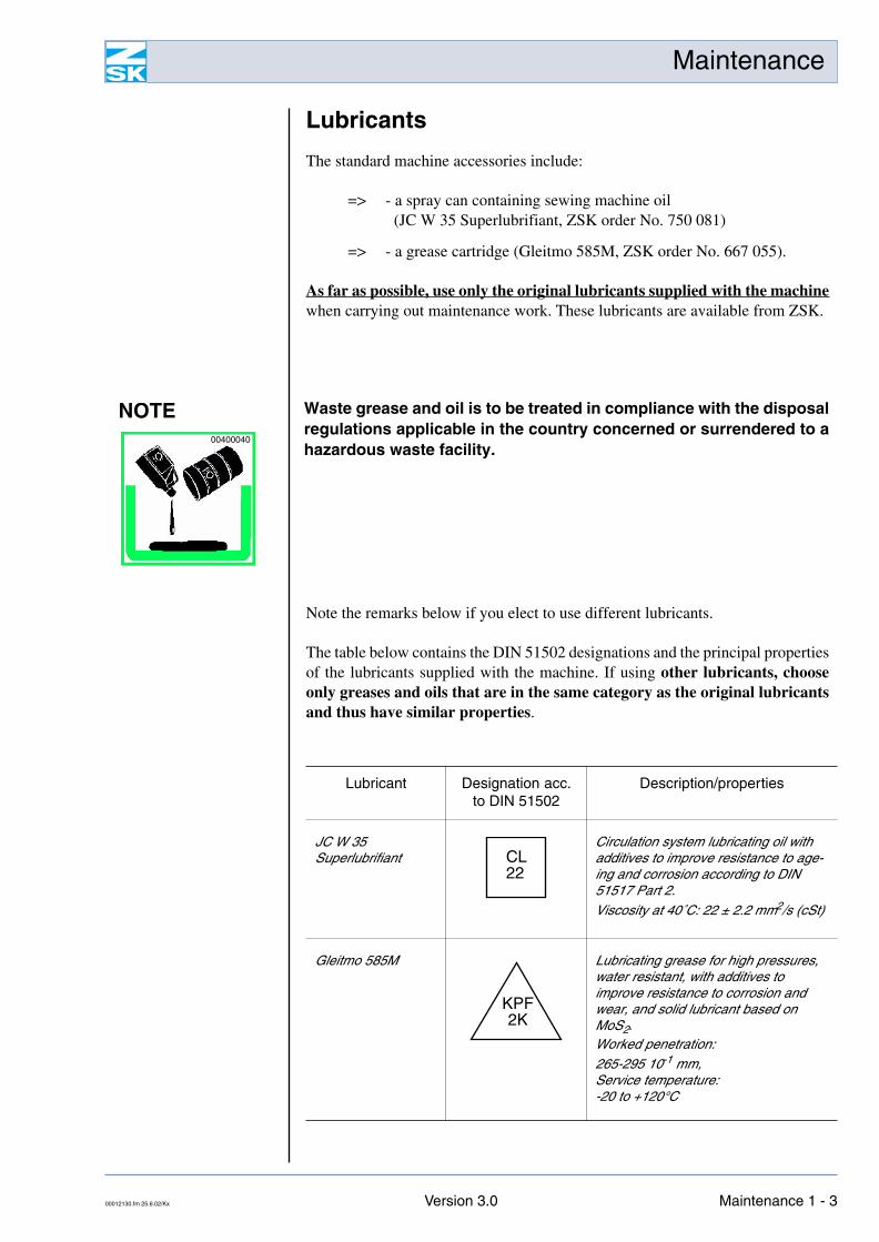
NOTE Waste grease and oil is to be treated in compliance with the disposalregulations applicable in the country concerned or surrendered to ahazardous waste facility.
00400040
Lubricant Designation acc. to DIN 51502
Description/properties
JC W 35Superlubrifiant
Circulation system lubricating oil with additives to improve resistance to age-ing and corrosion according to DIN 51517 Part 2.
Viscosity at 40˚C: 22 ± 2.2 mm2/s (cSt)
Gleitmo 585M Lubricating grease for high pressures, water resistant, with additives to improve resistance to corrosion and wear, and solid lubricant based on MoS2.Worked penetration:
265-295 10-1 mm,Service temperature:-20 to +120°C
CL22
KPF2K
00012130.fm 25.6.02/Kx Version 3.0 Maintenance 1 - 3
Maintenance
Maintenance work
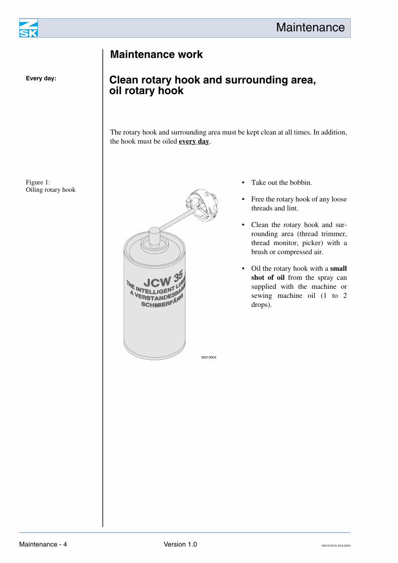
The rotary hook and surrounding area must be kept clean at all times. In addition,the hook must be oiled every day.
Every day: Clean rotary hook and surrounding area, oil rotary hook
Figure 1: Oiling rotary hook
• Take out the bobbin.
• Free the rotary hook of any loosethreads and lint.
• Clean the rotary hook and sur-rounding area (thread trimmer,thread monitor, picker) with abrush or compressed air.
• Oil the rotary hook with a smallshot of oil from the spray cansupplied with the machine orsewing machine oil (1 to 2drops).
00013004
Maintenance - 4 Version 1.0 00012130.fm 25.6.02/Kx
Maintenance
Foot plate: variant 1
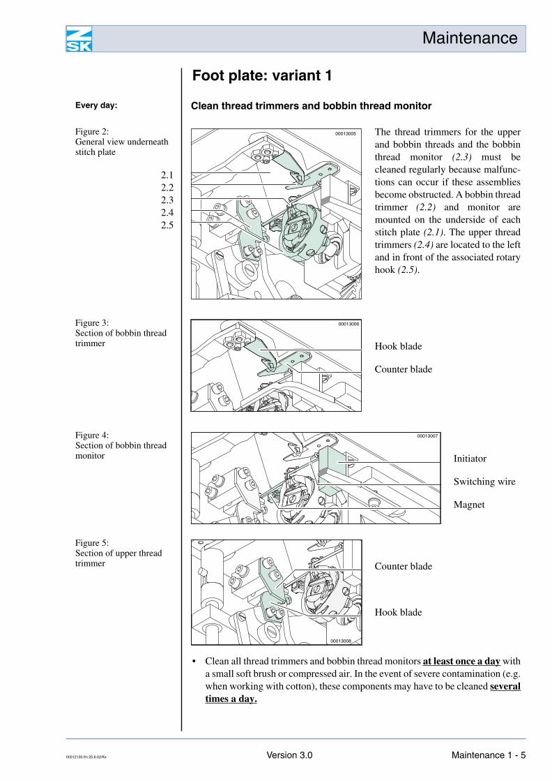
• Clean all thread trimmers and bobbin thread monitors at least once a day witha small soft brush or compressed air. In the event of severe contamination (e.g.when working with cotton), these components may have to be cleaned severaltimes a day.
Every day: Clean thread trimmers and bobbin thread monitor
Figure 2: General view underneath stitch plate
2.12.22.32.42.5
The thread trimmers for the upperand bobbin threads and the bobbinthread monitor (2.3) must becleaned regularly because malfunc-tions can occur if these assembliesbecome obstructed. A bobbin threadtrimmer (2.2) and monitor aremounted on the underside of eachstitch plate (2.1). The upper threadtrimmers (2.4) are located to the leftand in front of the associated rotaryhook (2.5).
00013005
Figure 3: Section of bobbin thread trimmer Hook blade
Counter blade
00013006
Figure 4: Section of bobbin thread monitor Initiator
Switching wire
Magnet
00013007
Figure 5: Section of upper thread trimmer Counter blade
Hook blade
00013008
00012130.fm 25.6.02/Kx Version 3.0 Maintenance 1 - 5
Maintenance
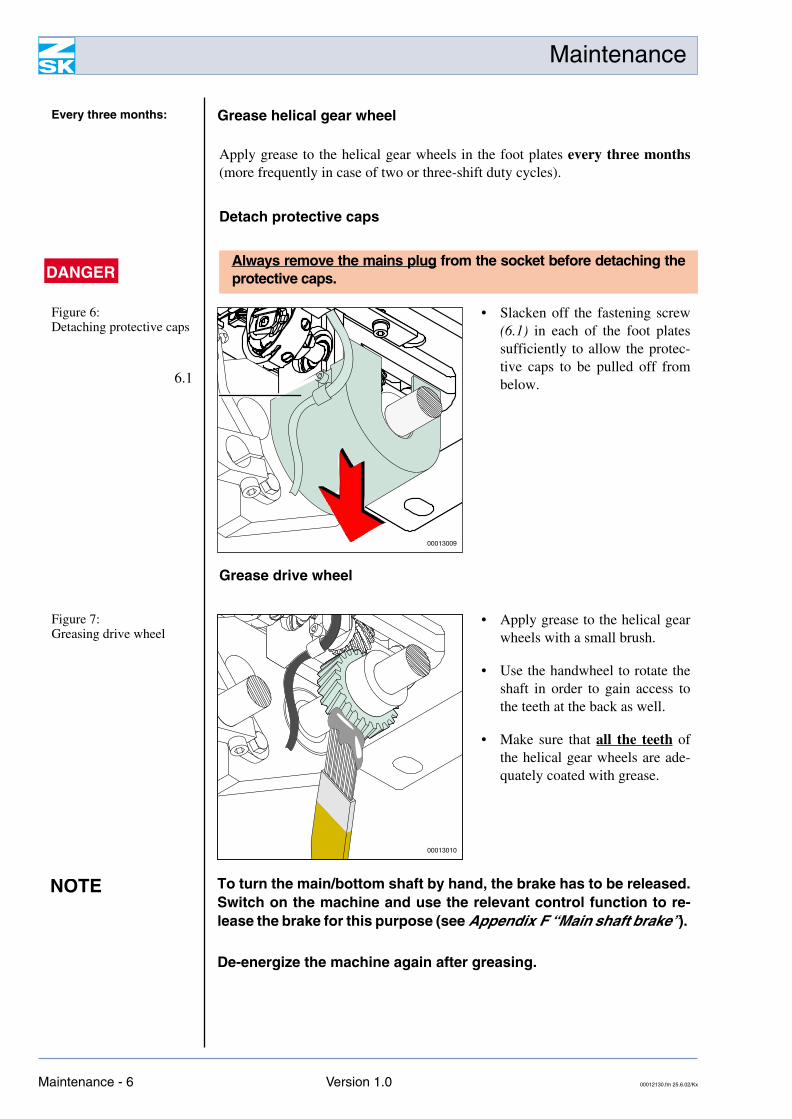
Apply grease to the helical gear wheels in the foot plates every three months(more frequently in case of two or three-shift duty cycles).
Detach protective caps
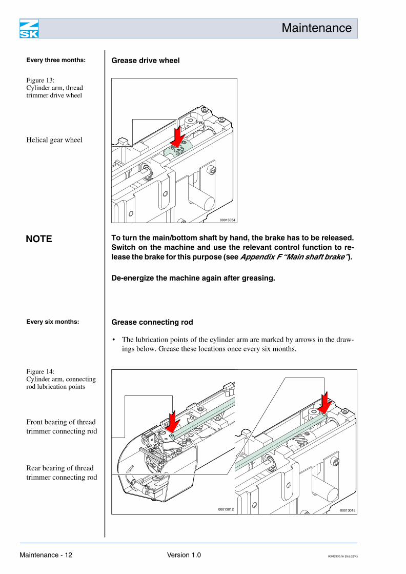
Grease drive wheel
Every three months: Grease helical gear wheel
DANGERAlways remove the mains plug from the socket before detaching theprotective caps.
Figure 6: Detaching protective caps
6.1
• Slacken off the fastening screw(6.1) in each of the foot platessufficiently to allow the protec-tive caps to be pulled off frombelow.
00013009
Figure 7: Greasing drive wheel
• Apply grease to the helical gearwheels with a small brush.
• Use the handwheel to rotate theshaft in order to gain access tothe teeth at the back as well.
• Make sure that all the teeth ofthe helical gear wheels are ade-quately coated with grease.
00013010
NOTE To turn the main/bottom shaft by hand, the brake has to be released.Switch on the machine and use the relevant control function to re-lease the brake for this purpose (see Appendix F “Main shaft brake”).
De-energize the machine again after greasing.
Maintenance - 6 Version 1.0 00012130.fm 25.6.02/Kx
Maintenance
Install protective caps
DANGERProperly secure all the protective caps again with the Allenscrews. The caps are provided for your own safety and to protectthe helical gear wheels against contamination.
00012130.fm 25.6.02/Kx Version 3.0 Maintenance 1 - 7
Maintenance
Clean thread trimmer
• Clean the thread trimmer area of the foot plate with compressed air or a brush.
Thread trimmer drive
Every day: Foot plate: variant 2
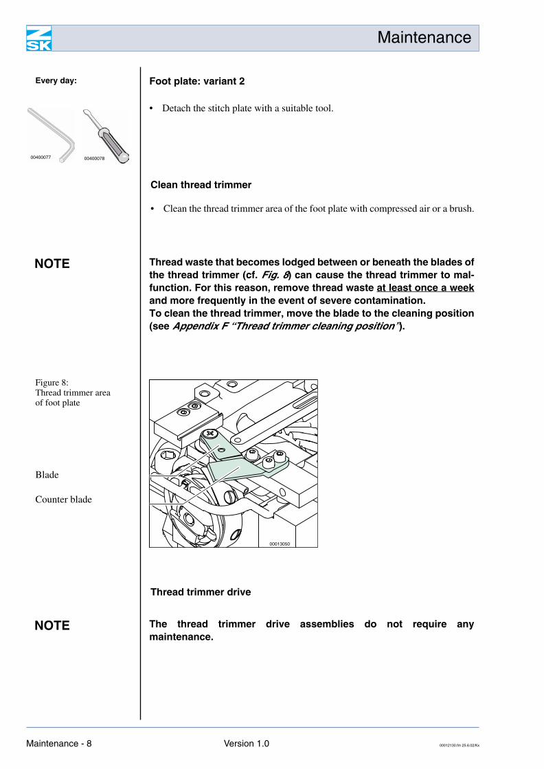
• Detach the stitch plate with a suitable tool.
0040007800400077
NOTE Thread waste that becomes lodged between or beneath the blades ofthe thread trimmer (cf. Fig. 8) can cause the thread trimmer to mal-function. For this reason, remove thread waste at least once a weekand more frequently in the event of severe contamination.To clean the thread trimmer, move the blade to the cleaning position(see Appendix F “Thread trimmer cleaning position”).
Figure 8: Thread trimmer areaof foot plate
Blade
Counter blade
00013050
NOTE The thread trimmer drive assemblies do not require anymaintenance.
Maintenance - 8 Version 1.0 00012130.fm 25.6.02/Kx
Maintenance
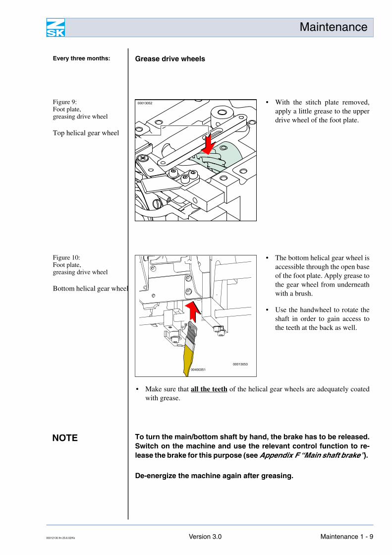
• Make sure that all the teeth of the helical gear wheels are adequately coatedwith grease.
Every three months: Grease drive wheels
Figure 9: Foot plate, greasing drive wheel
Top helical gear wheel
• With the stitch plate removed,apply a little grease to the upperdrive wheel of the foot plate.
00013052
Figure 10: Foot plate, greasing drive wheel
Bottom helical gear wheel
• The bottom helical gear wheel isaccessible through the open baseof the foot plate. Apply grease tothe gear wheel from underneathwith a brush.
• Use the handwheel to rotate theshaft in order to gain access tothe teeth at the back as well.
00400351
00013053
NOTE To turn the main/bottom shaft by hand, the brake has to be released.Switch on the machine and use the relevant control function to re-lease the brake for this purpose (see Appendix F “Main shaft brake”).
De-energize the machine again after greasing.
00012130.fm 25.6.02/Kx Version 3.0 Maintenance 1 - 9
Maintenance
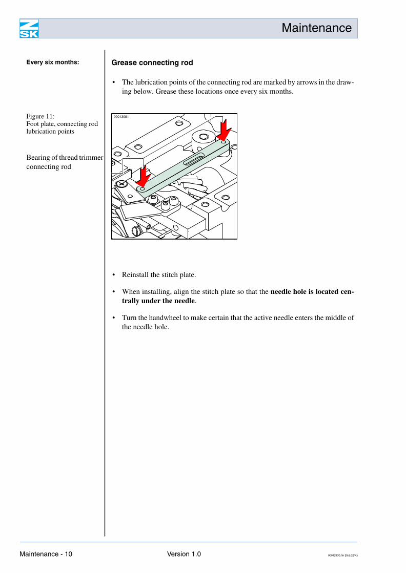
• The lubrication points of the connecting rod are marked by arrows in the draw-ing below. Grease these locations once every six months.
• Reinstall the stitch plate.
• When installing, align the stitch plate so that the needle hole is located cen-trally under the needle.
• Turn the handwheel to make certain that the active needle enters the middle ofthe needle hole.
Every six months: Grease connecting rod
Figure 11: Foot plate, connecting rod lubrication points
Bearing of thread trimmer connecting rod
00013051
Maintenance - 10 Version 1.0 00012130.fm 25.6.02/Kx
Maintenance
Clean thread trimmer
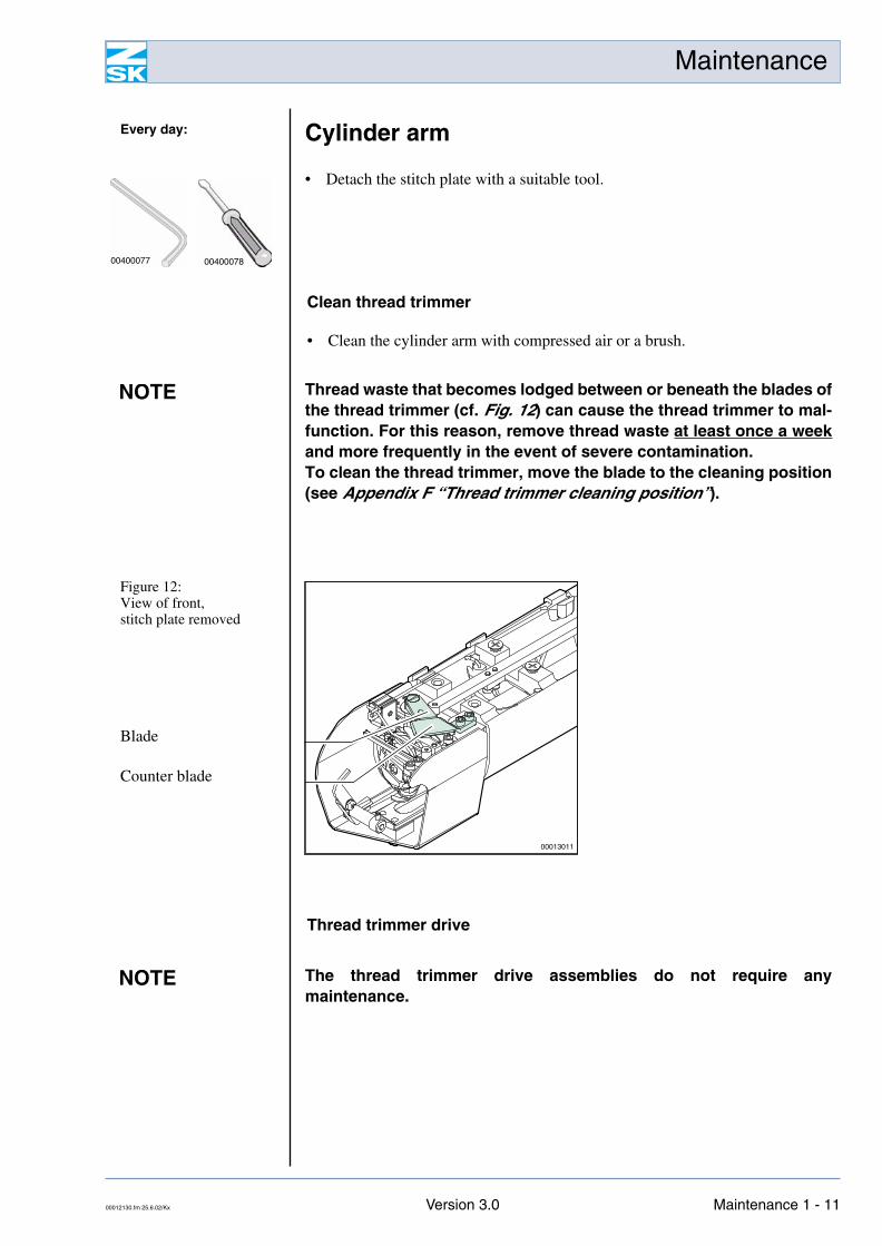
• Clean the cylinder arm with compressed air or a brush.
Thread trimmer drive
Every day: Cylinder arm
• Detach the stitch plate with a suitable tool.
0040007800400077
NOTE Thread waste that becomes lodged between or beneath the blades ofthe thread trimmer (cf. Fig. 12) can cause the thread trimmer to mal-function. For this reason, remove thread waste at least once a weekand more frequently in the event of severe contamination.To clean the thread trimmer, move the blade to the cleaning position(see Appendix F “Thread trimmer cleaning position”).
Figure 12: View of front,stitch plate removed
Blade
Counter blade
00013011
NOTE The thread trimmer drive assemblies do not require anymaintenance.
00012130.fm 25.6.02/Kx Version 3.0 Maintenance 1 - 11
Maintenance
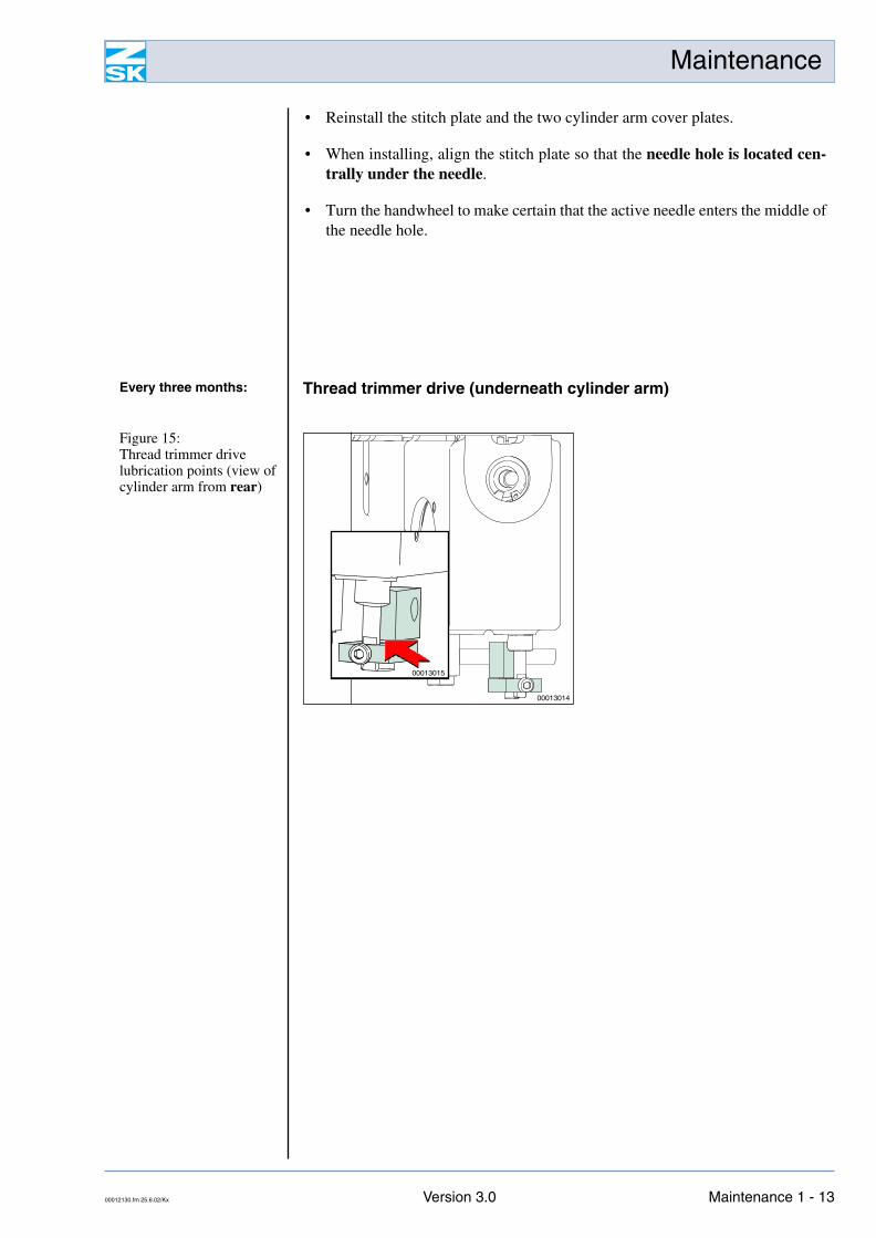
• The lubrication points of the cylinder arm are marked by arrows in the draw-ings below. Grease these locations once every six months.
NOTE To turn the main/bottom shaft by hand, the brake has to be released.Switch on the machine and use the relevant control function to re-lease the brake for this purpose (see Appendix F “Main shaft brake”).
De-energize the machine again after greasing.
Every six months: Grease connecting rod
Figure 14: Cylinder arm, connecting rod lubrication points
Front bearing of thread trimmer connecting rod
Rear bearing of thread trimmer connecting rod
00013012 00013013
Maintenance - 12 Version 1.0 00012130.fm 25.6.02/Kx
Maintenance
• Reinstall the stitch plate and the two cylinder arm cover plates.
• When installing, align the stitch plate so that the needle hole is located cen-trally under the needle.
• Turn the handwheel to make certain that the active needle enters the middle ofthe needle hole.
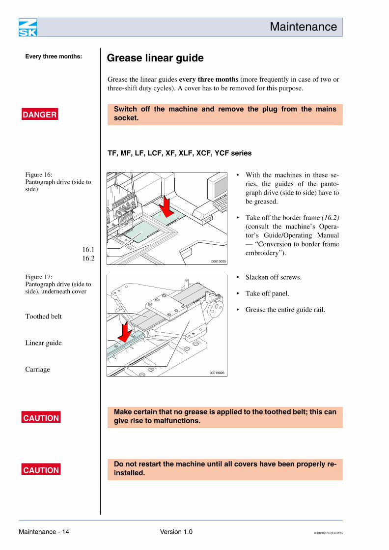
Every three months: Thread trimmer drive (underneath cylinder arm)
Figure 15: Thread trimmer drive lubrication points (view of cylinder arm from rear)
00013014
00013015
00012130.fm 25.6.02/Kx Version 3.0 Maintenance 1 - 13
Maintenance
Grease the linear guides every three months (more frequently in case of two orthree-shift duty cycles). A cover has to be removed for this purpose.
TF, MF, LF, LCF, XF, XLF, XCF, YCF series
Every three months: Grease linear guide
DANGERSwitch off the machine and remove the plug from the mainssocket.
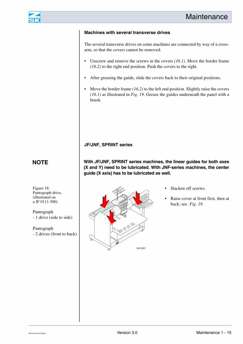
Figure 16: Pantograph drive (side to side)
16.116.2
• With the machines in these se-ries, the guides of the panto-graph drive (side to side) have tobe greased.
• Take off the border frame (16.2)(consult the machine’s Opera-tor’s Guide/Operating Manual— “Conversion to border frameembroidery”).
00013025
Figure 17: Pantograph drive (side to side), underneath cover
Toothed belt
Linear guide
Carriage
• Slacken off screws.
• Take off panel.
• Grease the entire guide rail.
00013026
CAUTIONMake certain that no grease is applied to the toothed belt; this cangive rise to malfunctions.
CAUTIONDo not restart the machine until all covers have been properly re-installed.
Maintenance - 14 Version 1.0 00012130.fm 25.6.02/Kx
Maintenance
Machines with several transverse drives
The several transverse drives on some machines are connected by way of a cross-arm, so that the covers cannot be removed.
• Unscrew and remove the screws in the covers (16.1). Move the border frame(16.2) to the right end position. Push the covers to the right.
• After greasing the guide, slide the covers back to their original positions.
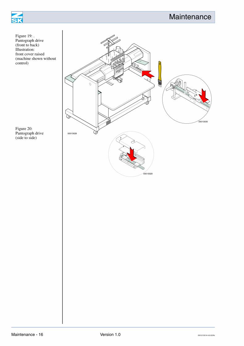
• Move the border frame (16.2) to the left end position. Slightly raise the covers(16.1) as illustrated in Fig. 19. Grease the guides underneath the panel with abrush.
JF/JNF, SPRINT series
NOTE With JF/JNF, SPRINT series machines, the linear guides for both axes(X and Y) need to be lubricated. With JNF-series machines, the centerguide (X axis) has to be lubricated as well.
Figure 18: Pantograph drive, (illustrated ona JF 0111-500)
Pantograph- 1 drive (side to side)
Pantograph- 2 drives (front to back)
• Slacken off screws.
• Raise cover at front first, then atback; see Fig. 19.
JF0111500
00013027
00012130.fm 6.8.02/Kx Version 3.0 Maintenance 1 - 15
Maintenance
Figure 19: .Pantograph drive(front to back)Illustration:front cover raised(machine shown without control)
Figure 20: Pantograph drive(side to side)
JF0111500
00013028
00013030
00013029
Maintenance - 16 Version 1.0 00012130.fm 6.8.02/Kx
Maintenance
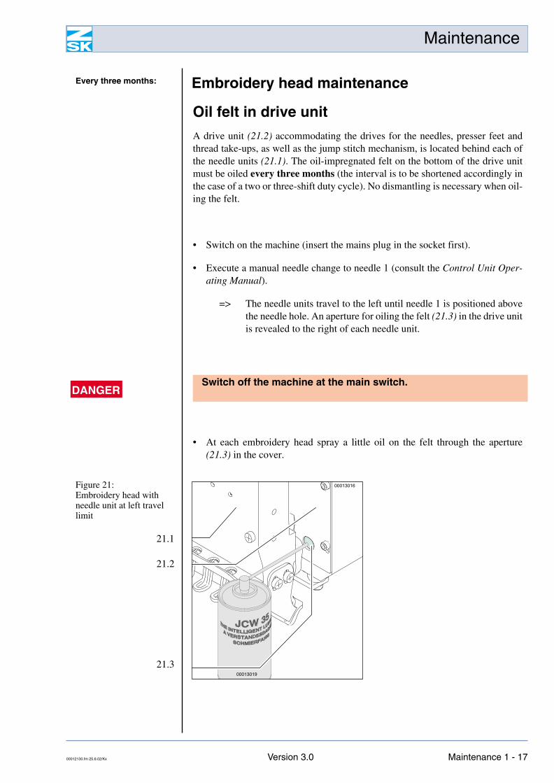
Oil felt in drive unit
A drive unit (21.2) accommodating the drives for the needles, presser feet andthread take-ups, as well as the jump stitch mechanism, is located behind each ofthe needle units (21.1). The oil-impregnated felt on the bottom of the drive unitmust be oiled every three months (the interval is to be shortened accordingly inthe case of a two or three-shift duty cycle). No dismantling is necessary when oil-ing the felt.
• Switch on the machine (insert the mains plug in the socket first).
• Execute a manual needle change to needle 1 (consult the Control Unit Oper-ating Manual).
=> The needle units travel to the left until needle 1 is positioned abovethe needle hole. An aperture for oiling the felt (21.3) in the drive unitis revealed to the right of each needle unit.
• At each embroidery head spray a little oil on the felt through the aperture(21.3) in the cover.
Every three months: Embroidery head maintenance
DANGERSwitch off the machine at the main switch.
Figure 21: Embroidery head with needle unit at left travel limit
21.1
21.2
21.300013019
00013016
00012130.fm 25.6.02/Kx Version 3.0 Maintenance 1 - 17
Maintenance
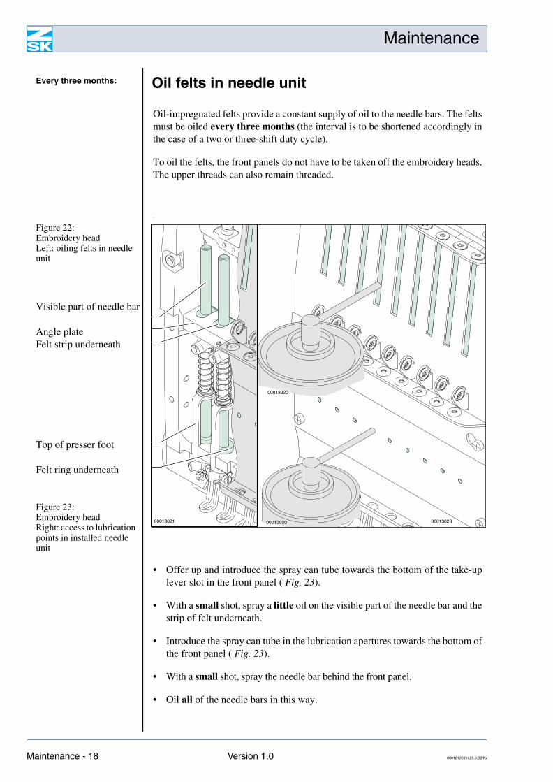
Oil-impregnated felts provide a constant supply of oil to the needle bars. The feltsmust be oiled every three months (the interval is to be shortened accordingly inthe case of a two or three-shift duty cycle).
To oil the felts, the front panels do not have to be taken off the embroidery heads.The upper threads can also remain threaded.
s
• Offer up and introduce the spray can tube towards the bottom of the take-uplever slot in the front panel ( Fig. 23).
• With a small shot, spray a little oil on the visible part of the needle bar and thestrip of felt underneath.
• Introduce the spray can tube in the lubrication apertures towards the bottom ofthe front panel ( Fig. 23).
• With a small shot, spray the needle bar behind the front panel.
• Oil all of the needle bars in this way.
Every three months: Oil felts in needle unit
Figure 22: Embroidery headLeft: oiling felts in needle unit
Visible part of needle bar
Angle plateFelt strip underneath
Top of presser foot
Felt ring underneath
Figure 23: Embroidery headRight: access to lubrication points in installed needle unit
0001302300013020
00013020
00013021
Maintenance - 18 Version 1.0 00012130.fm 25.6.02/Kx
Maintenance
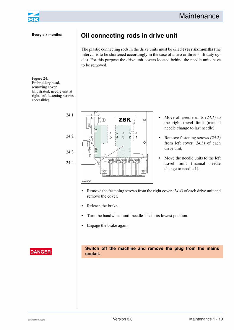
The plastic connecting rods in the drive units must be oiled every six months (theinterval is to be shortened accordingly in the case of a two or three-shift duty cy-cle). For this purpose the drive unit covers located behind the needle units haveto be removed.
• Remove the fastening screws from the right cover (24.4) of each drive unit andremove the cover.
• Release the brake.
• Turn the handwheel until needle 1 is in its lowest position.
• Engage the brake again.
Every six months: Oil connecting rods in drive unit
Figure 24: Embroidery head, removing cover(illustrated: needle unit at right, left fastening screws accessible)
24.1
24.2
24.3
24.4
• Move all needle units (24.1) tothe right travel limit (manualneedle change to last needle).
• Remove fastening screws (24.2)from left cover (24.3) of eachdrive unit.
• Move the needle units to the lefttravel limit (manual needlechange to needle 1).
ZSK
12345
00013048
DANGERSwitch off the machine and remove the plug from the mainssocket.
00012130.fm 25.6.02/Kx Version 3.0 Maintenance 1 - 19
Maintenance
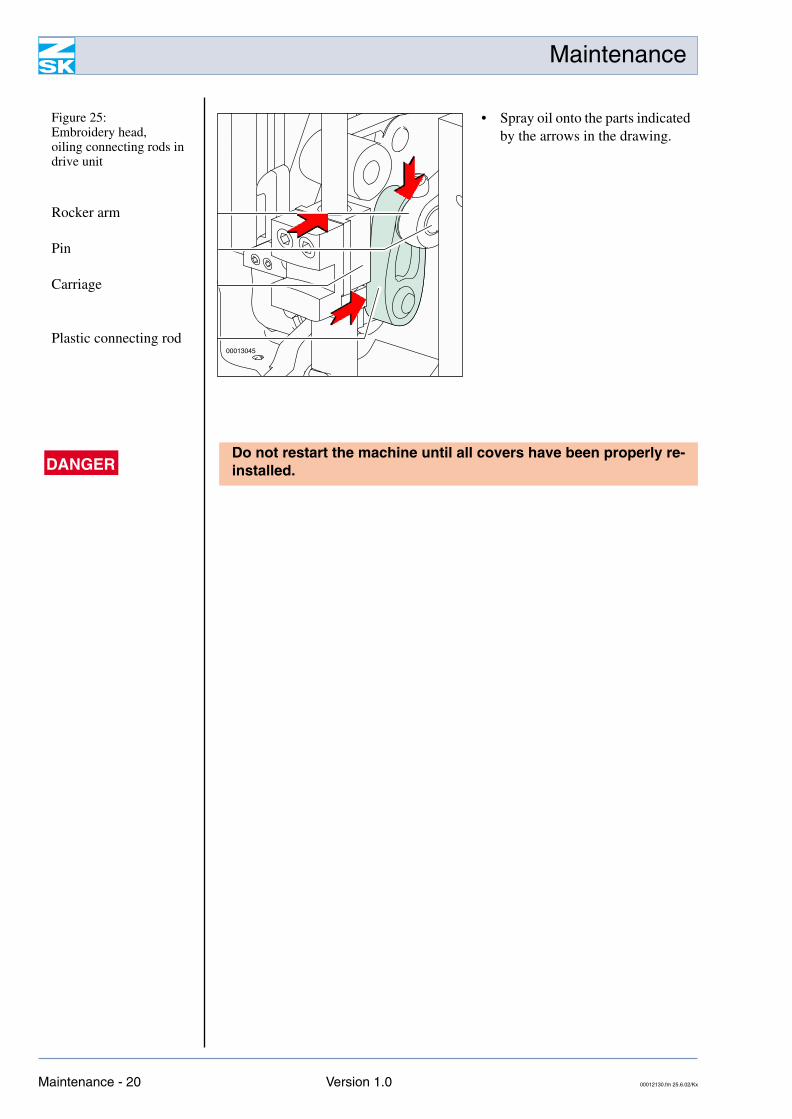
Figure 25: Embroidery head, oiling connecting rods in drive unit
Rocker arm
Pin
Carriage
Plastic connecting rod
• Spray oil onto the parts indicatedby the arrows in the drawing.
00013045
DANGERDo not restart the machine until all covers have been properly re-installed.
Maintenance - 20 Version 1.0 00012130.fm 25.6.02/Kx
Maintenance
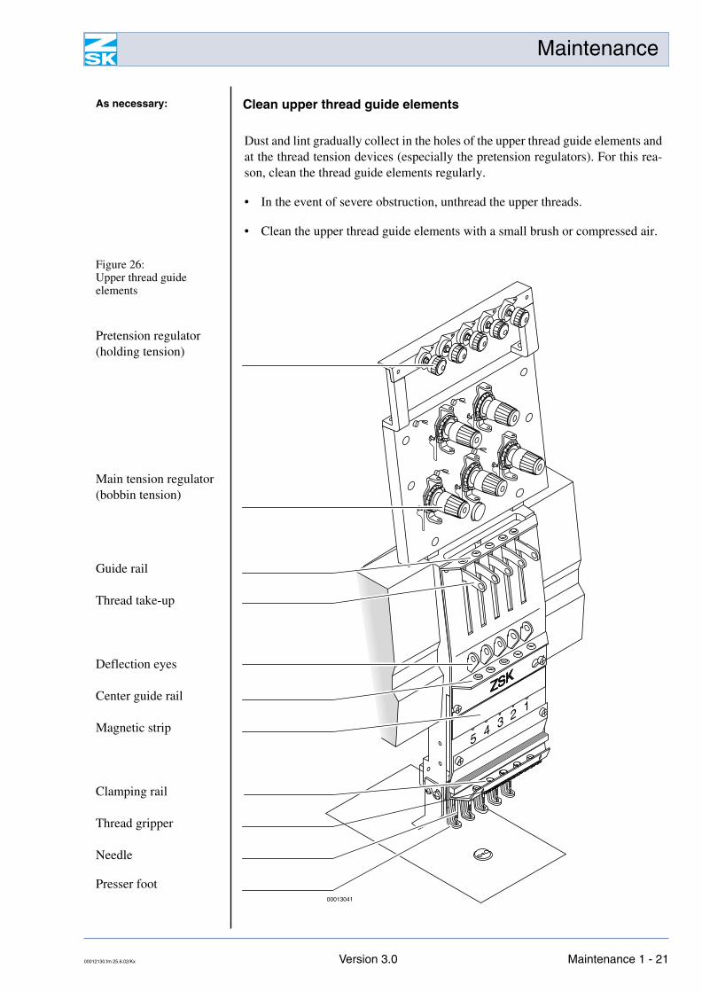
Dust and lint gradually collect in the holes of the upper thread guide elements andat the thread tension devices (especially the pretension regulators). For this rea-son, clean the thread guide elements regularly.
• In the event of severe obstruction, unthread the upper threads.
• Clean the upper thread guide elements with a small brush or compressed air.
As necessary: Clean upper thread guide elements
Figure 26: Upper thread guide elements
Pretension regulator(holding tension)
Main tension regulator(bobbin tension)
Guide rail
Thread take-up
Deflection eyes
Center guide rail
Magnetic strip
Clamping rail
Thread gripper
Needle
Presser foot00013041
00012130.fm 25.6.02/Kx Version 3.0 Maintenance 1 - 21
Maintenance
Optional machine attachments
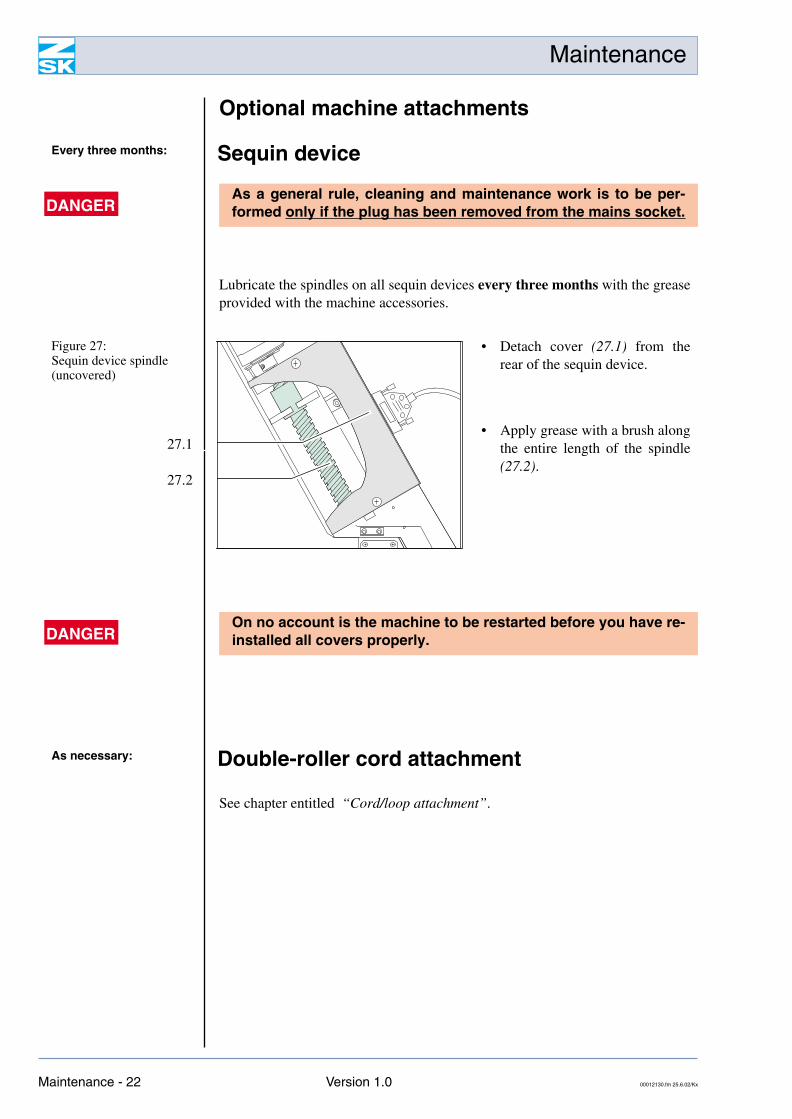
Lubricate the spindles on all sequin devices every three months with the greaseprovided with the machine accessories.
See chapter entitled “Cord/loop attachment”.
Every three months: Sequin device
DANGERAs a general rule, cleaning and maintenance work is to be per-formed only if the plug has been removed from the mains socket.
Figure 27: Sequin device spindle(uncovered)
27.1
27.2
• Detach cover (27.1) from therear of the sequin device.
• Apply grease with a brush alongthe entire length of the spindle(27.2).
DANGEROn no account is the machine to be restarted before you have re-installed all covers properly.
As necessary: Double-roller cord attachment
Maintenance - 22 Version 1.0 00012130.fm 25.6.02/Kx
Maintenance
As necessary: Cord/loop attachment
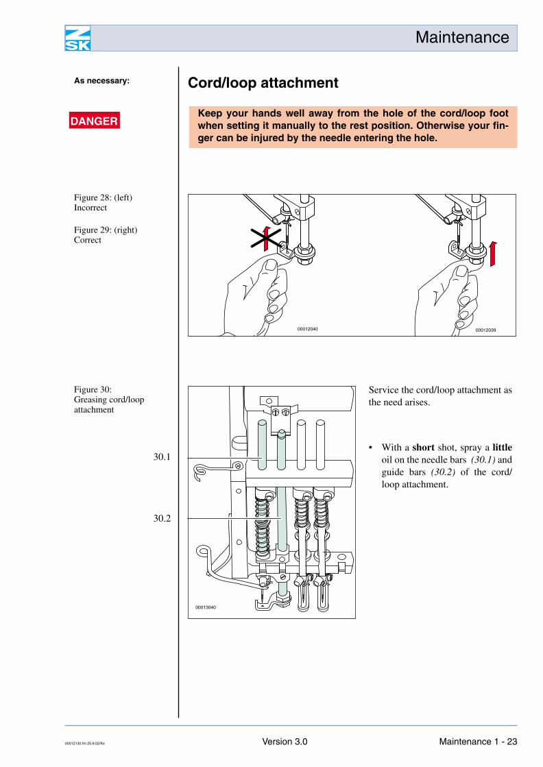
DANGERKeep your hands well away from the hole of the cord/loop footwhen setting it manually to the rest position. Otherwise your fin-ger can be injured by the needle entering the hole.
Figure 28: (left)Incorrect
Figure 29: (right)Correct
0001203900012040
Figure 30: Greasing cord/loop attachment
30.1
30.2
Service the cord/loop attachment asthe need arises.
• With a short shot, spray a littleoil on the needle bars (30.1) andguide bars (30.2) of the cord/loop attachment.
00013040
00012130.fm 25.6.02/Kx Version 3.0 Maintenance 1 - 23
Maintenance
Change borer
Adjusting borer height
As necessary: Boring attachment
DANGERThe borer is a cutting tool and therefore razor sharp. Observe thefollowing safety instructions to avoid injury:
- Never touch the tip of the borer, always hold it by the shank.
- Free borers that have become jammed with a suitable pair offlat nose pliers.
- Do not leave dismantled borers on the work table or anywhereelse on the machine. Clear away loose borers immediately toavoid causing injury to yourself and others.
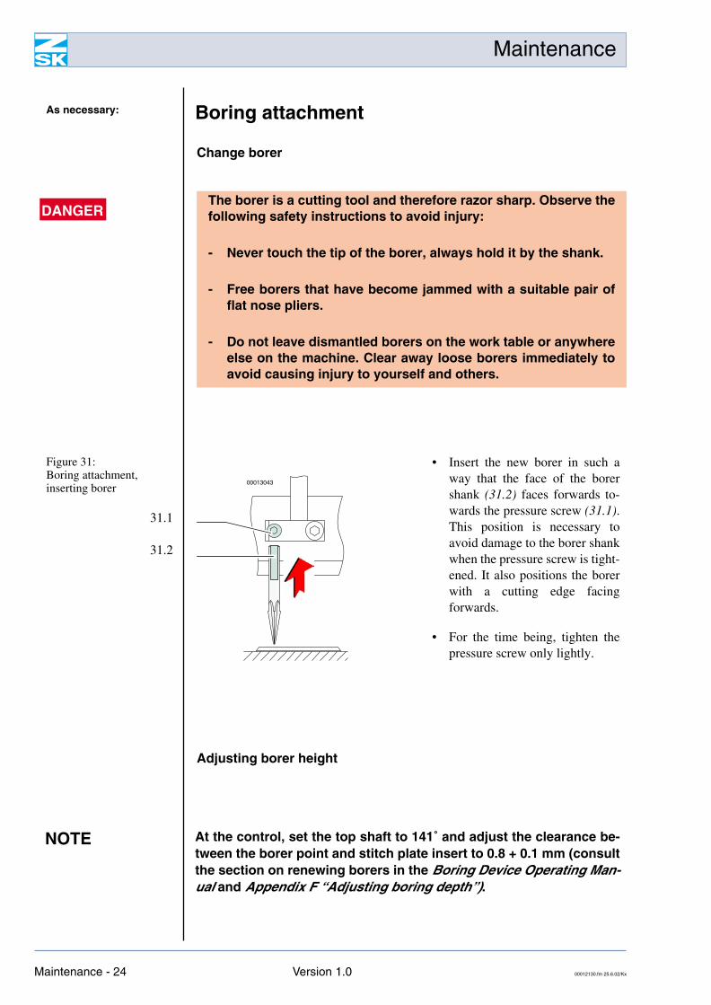
Figure 31: Boring attachment, inserting borer
31.1
31.2
• Insert the new borer in such away that the face of the borershank (31.2) faces forwards to-wards the pressure screw (31.1).This position is necessary toavoid damage to the borer shankwhen the pressure screw is tight-ened. It also positions the borerwith a cutting edge facingforwards.
• For the time being, tighten thepressure screw only lightly.
00013043
NOTE At the control, set the top shaft to 141˚ and adjust the clearance be-tween the borer point and stitch plate insert to 0.8 + 0.1 mm (consultthe section on renewing borers in the Boring Device Operating Man-ual and Appendix F “Adjusting boring depth”).
Maintenance - 24 Version 1.0 00012130.fm 25.6.02/Kx
Maintenance
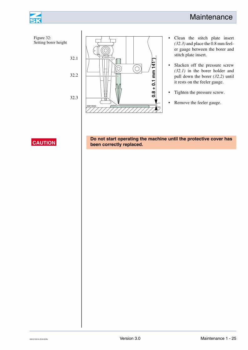
Figure 32: Setting borer height
32.1
32.2
32.3
• Clean the stitch plate insert(32.3) and place the 0.8 mm feel-er gauge between the borer andstitch plate insert.
• Slacken off the pressure screw(32.1) in the borer holder andpull down the borer (32.2) untilit rests on the feeler gauge.
• Tighten the pressure screw.
• Remove the feeler gauge.00013042
0.8
+ 0.
1 m
m 1
41°)
CAUTIONDo not start operating the machine until the protective cover hasbeen correctly replaced.
00012130.fm 25.6.02/Kx Version 3.0 Maintenance 1 - 25
Maintenance
Cap attachment ’99
Rotary hook changer
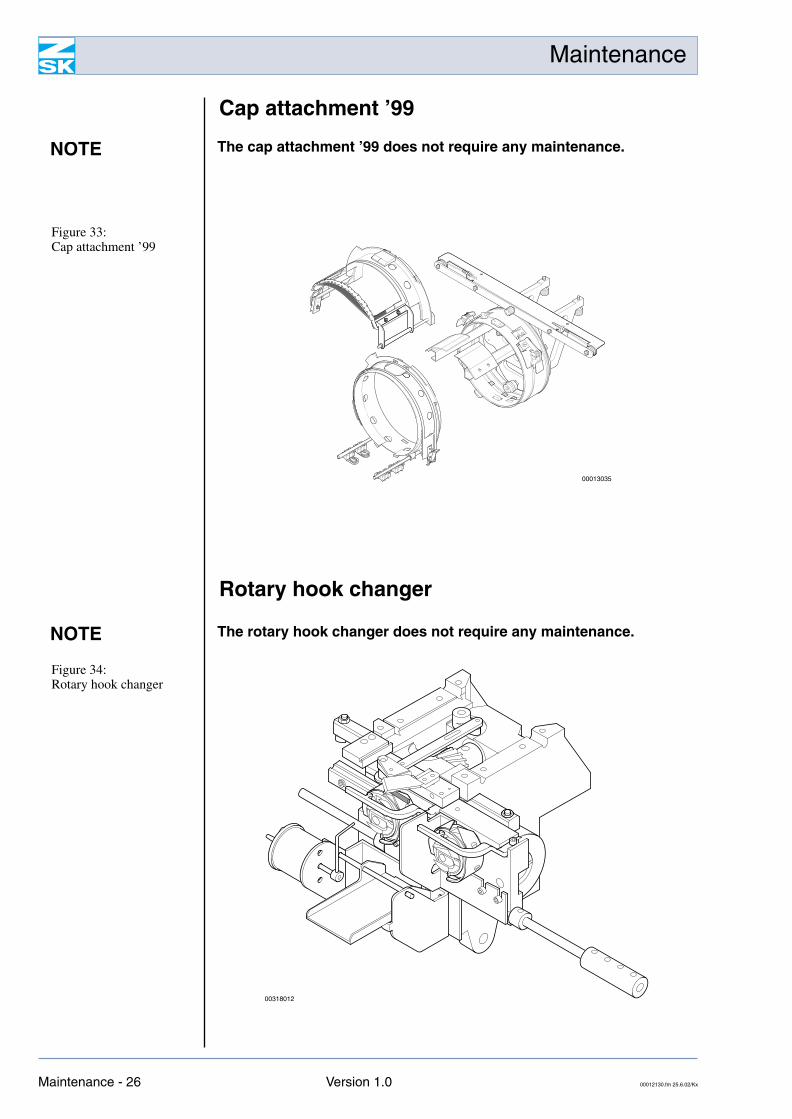
NOTE The cap attachment ’99 does not require any maintenance.
Figure 33: Cap attachment ’99
00013035
NOTE The rotary hook changer does not require any maintenance.
Figure 34: Rotary hook changer
00318012
Maintenance - 26 Version 1.0 00012130.fm 25.6.02/Kx
Maintenance
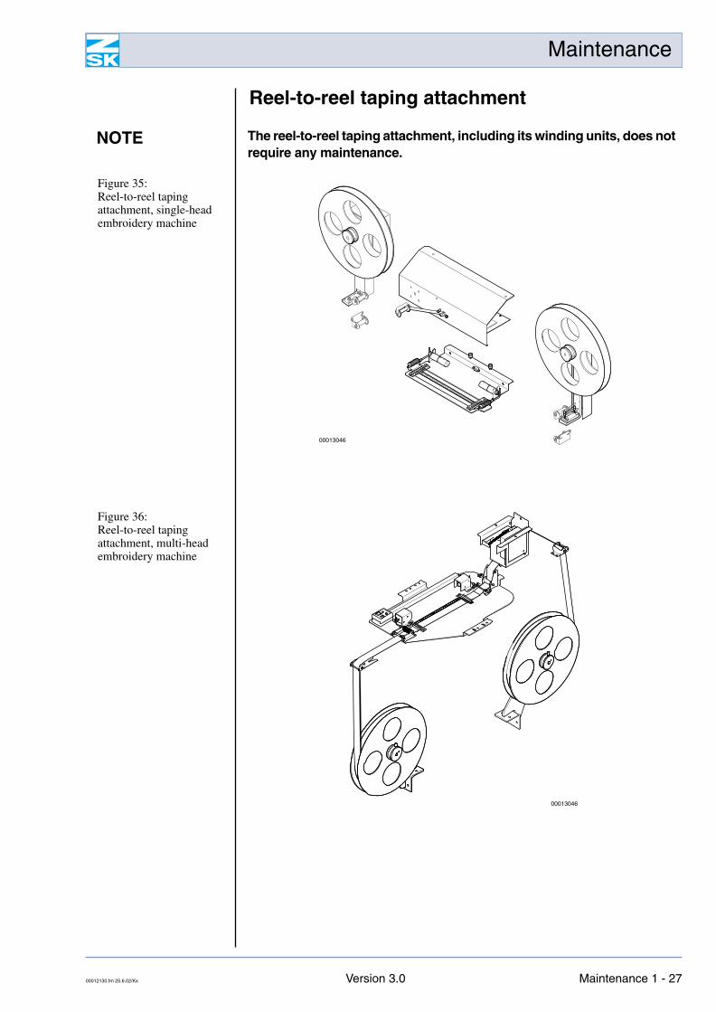
Reel-to-reel taping attachment
NOTE The reel-to-reel taping attachment, including its winding units, does notrequire any maintenance.
00012130.fm 25.6.02/Kx Version 3.0 Maintenance 1 - 27
Maintenance
Servicing the control components
Clean control components
Air vents in control cabinet
DANGERControl components are to be installed, repaired and adjusted only bytrained service personnel.
DANGERClean the control cabinet, screen, keyboard and disk drive only ifthe plug has been removed from the mains socket.
NOTE Clean plastic parts with a soft, non-fluffy, slightly damp cloth. Do notuse any caustic or ammonia-containing cleaning agents, or abrasiveagents or sprays. On no account are liquids allowed to enter anydevices.
The screen can be cleaned with special anti-static cleaning cloths orconventional glass cleaning agents. Here again, sprays are not to beused on any account. The spray mist could enter the cabinet anddamage the screen beyond repair.
CAUTIONMake certain that all air vents ( Fig. 37) in the control cabinet re-main unobstructed at all times. Inadequate venting can causeoverheating and damage the control components.
Maintenance - 28 Version 1.0 00012130.fm 25.6.02/Kx
Maintenance
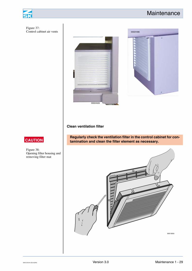
Clean ventilation filter
Figure 37: Control cabinet air vents
00024509
00024486
CAUTIONRegularly check the ventilation filter in the control cabinet for con-tamination and clean the filter element as necessary.
Figure 38: Opening filter housing and removing filter mat
00013055
00012130.fm 25.6.02/Kx Version 3.0 Maintenance 1 - 29
Maintenance
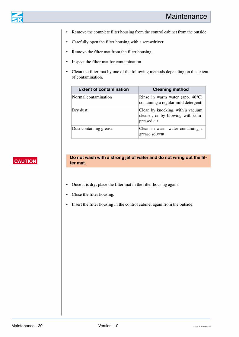
• Remove the complete filter housing from the control cabinet from the outside.
• Carefully open the filter housing with a screwdriver.
• Remove the filter mat from the filter housing.
• Inspect the filter mat for contamination.
• Clean the filter mat by one of the following methods depending on the extentof contamination.
• Once it is dry, place the filter mat in the filter housing again.
• Close the filter housing.
• Insert the filter housing in the control cabinet again from the outside.
Extent of contamination Cleaning method
Normal contamination Rinse in warm water (app. 40°C)containing a regular mild detergent.
Dry dust Clean by knocking, with a vacuumcleaner, or by blowing with com-pressed air.
Dust containing grease Clean in warm water containing agrease solvent.
CAUTIONDo not wash with a strong jet of water and do not wring out the fil-ter mat.
Maintenance - 30 Version 1.0 00012130.fm 25.6.02/Kx
Appendix D – Needle/Rotary Hook Adjustment
Appendix D – Needle/Rotary Hook Adjustment
The values stated below are intended to help a specialist make the correct settings.
CAUTION
Adjusting loop stroke/needle depth
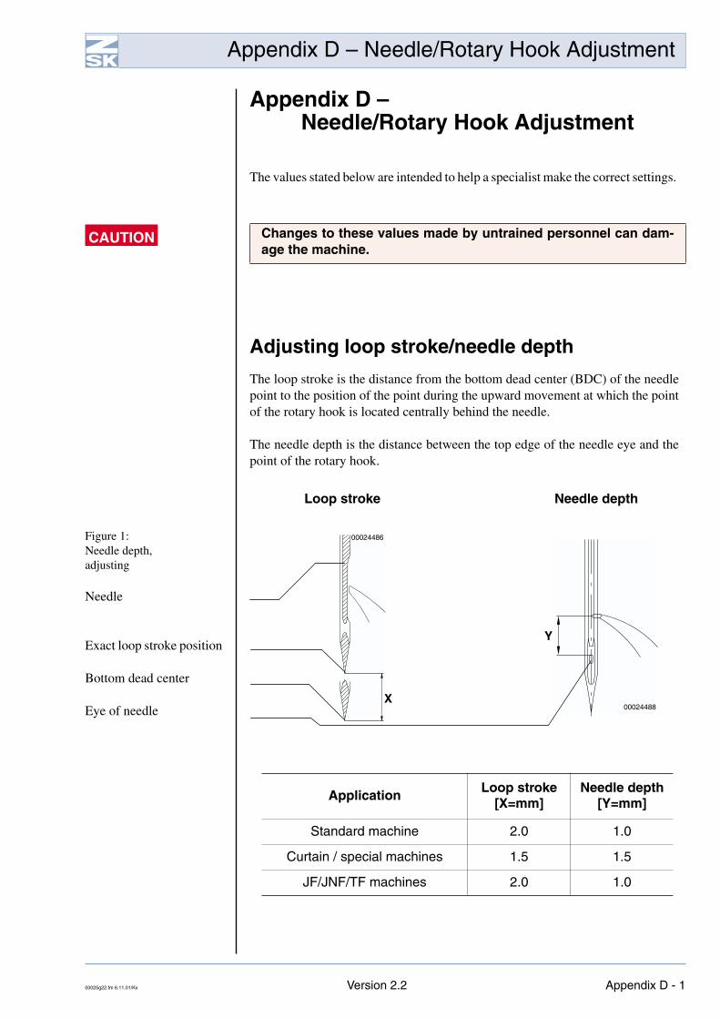
The loop stroke is the distance from the bottom dead center (BDC) of the needlepoint to the position of the point during the upward movement at which the pointof the rotary hook is located centrally behind the needle.
The needle depth is the distance between the top edge of the needle eye and thepoint of the rotary hook.
Loop stroke Needle depth
Figure 1: Needle depth,adjusting
Needle
Exact loop stroke position
Bottom dead center
Eye of needle
Changes to these values made by untrained personnel can dam-age the machine.
Application Loop stroke[X=mm]
Needle depth[Y=mm]
Standard machine 2.0 1.0
Curtain / special machines 1.5 1.5
JF/JNF/TF machines 2.0 1.0
00024486
Y
00024488X
00025g22.fm 6.11.01/Kx Version 2.2 Appendix D - 1
Appendix D – Needle/Rotary Hook Adjustment
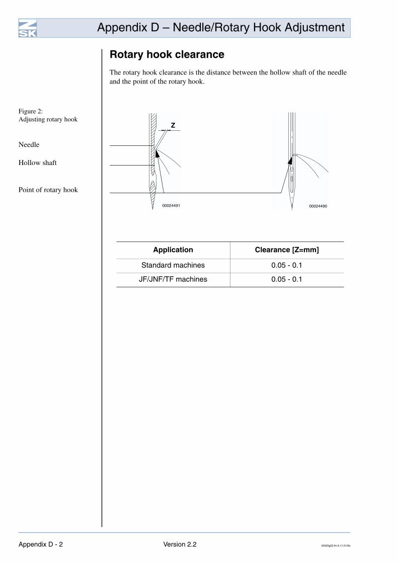
Rotary hook clearance
The rotary hook clearance is the distance between the hollow shaft of the needleand the point of the rotary hook.
Figure 2: Adjusting rotary hook
Needle
Hollow shaft
Point of rotary hook
Application Clearance [Z=mm]
Standard machines 0.05 - 0.1
JF/JNF/TF machines 0.05 - 0.1
Z
00024491 00024490
Appendix D - 2 Version 2.2 00025g22.fm 6.11.01/Kx
Appendix F – Adjustments – LCD
Appendix F – Adjustments – LCD
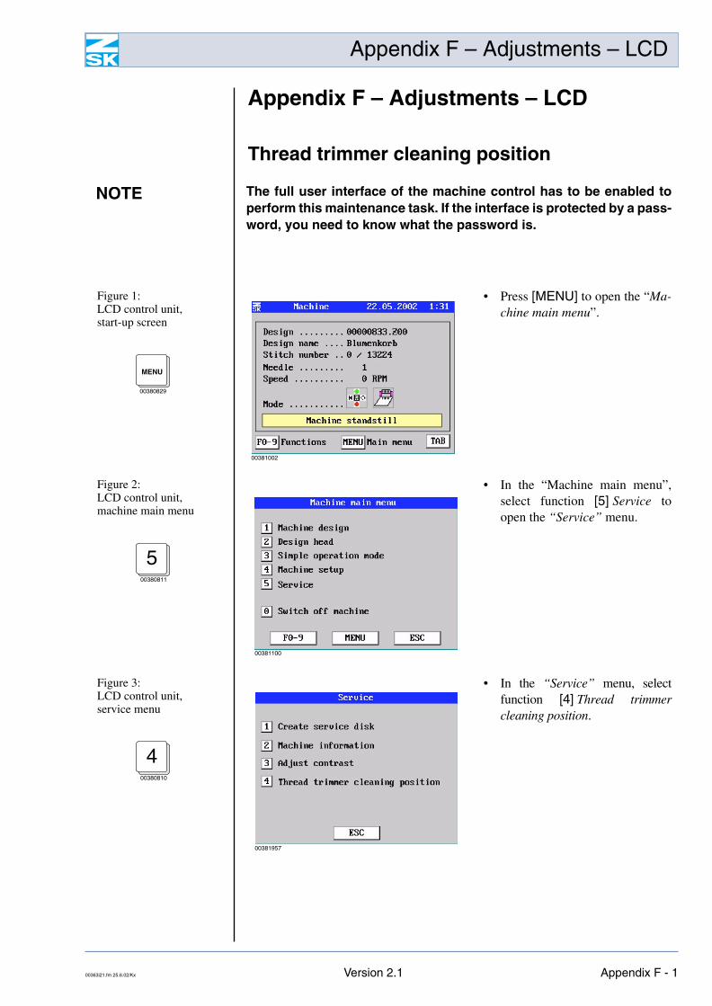
Thread trimmer cleaning position
NOTE The full user interface of the machine control has to be enabled toperform this maintenance task. If the interface is protected by a pass-word, you need to know what the password is.
Figure 1: LCD control unit,start-up screen
• Press [MENU] to open the “Ma-chine main menu”.
MENU
00380829
00381002
Figure 2: LCD control unit,machine main menu
• In the “Machine main menu”,select function [5] Service toopen the “Service” menu.
500380811
00381100
Figure 3: LCD control unit,service menu
• In the “Service” menu, selectfunction [4] Thread trimmercleaning position.
400380810
00381957
00363i21.fm 25.6.02/Kx Version 2.1 Appendix F - 1
Appendix F – Adjustments – LCD
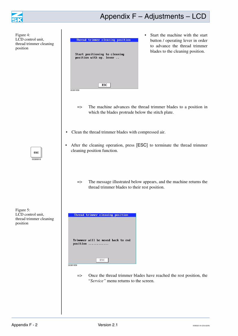
=> The machine advances the thread trimmer blades to a position inwhich the blades protrude below the stitch plate.
• Clean the thread trimmer blades with compressed air.
=> The message illustrated below appears, and the machine returns thethread trimmer blades to their rest position.
=> Once the thread trimmer blades have reached the rest position, the“Service” menu returns to the screen.
Figure 4: LCD control unit,thread trimmer cleaning position
• Start the machine with the startbutton / operating lever in orderto advance the thread trimmerblades to the cleaning position.
00381958
• After the cleaning operation, press [ESC] to terminate the thread trimmercleaning position function.
ESC
00380818
Figure 5: LCD control unit,thread trimmer cleaning position
00381959
Appendix F - 2 Version 2.1 00363i21.fm 25.6.02/Kx
Appendix F – Adjustments – LCD
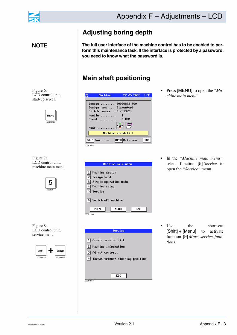
Adjusting boring depth
Main shaft positioning
NOTE The full user interface of the machine control has to be enabled to per-form this maintenance task. If the interface is protected by a password,you need to know what the password is.
Figure 6: LCD control unit,start-up screen
• Press [MENU] to open the “Ma-chine main menu”.
MENU
00380829
00381002
Figure 7: LCD control unit,machine main menu
• In the “Machine main menu”,select function [5] Service toopen the “Service” menu.
500380811
00381100
Figure 8: LCD control unit,service menu
• Use the short-cut[Shift] + [Menu] to activatefunction [9] More service func-tions.
MENU
00380829
SHIFT
00380825
+
00381957
00363i21.fm 25.6.02/Kx Version 2.1 Appendix F - 3
Appendix F – Adjustments – LCD
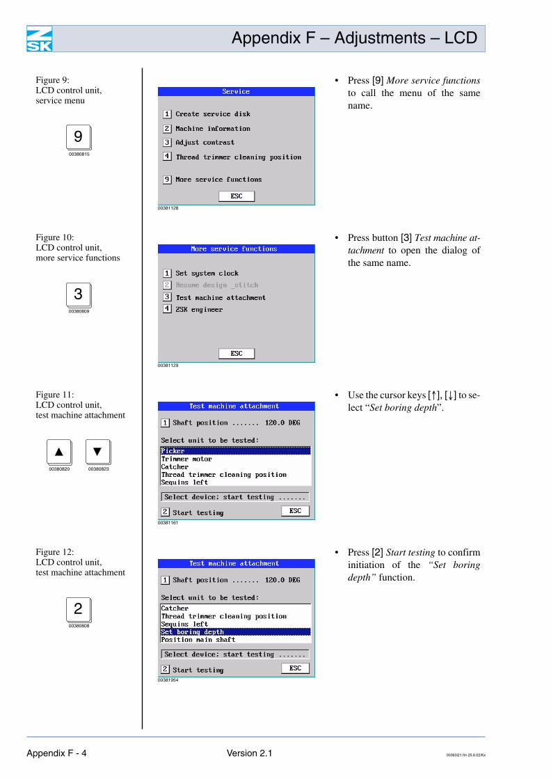
Figure 9: LCD control unit,service menu
• Press [9] More service functionsto call the menu of the samename.
900380815
00381128
Figure 10: LCD control unit,more service functions
• Press button [3] Test machine at-tachment to open the dialog ofthe same name.
300380809
00381129
Figure 11: LCD control unit,test machine attachment
• Use the cursor keys [↑], [↓] to se-lect “Set boring depth”.
00380820 00380823
00381161
Figure 12: LCD control unit,test machine attachment
• Press [2] Start testing to confirminitiation of the “Set boringdepth” function.
200380808
00381954
Appendix F - 4 Version 2.1 00363i21.fm 25.6.02/Kx
Appendix F – Adjustments – LCD
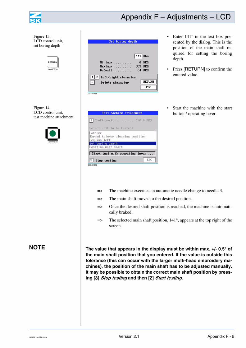
NOTE
=> The machine executes an automatic needle change to needle 3.
=> The main shaft moves to the desired position.
=> Once the desired shaft position is reached, the machine is automati-cally braked.
=> The selected main shaft position, 141°, appears at the top right of thescreen.
The value that appears in the display must be within max. +/- 0.5° ofthe main shaft position that you entered. If the value is outside thistolerance (this can occur with the larger multi-head embroidery ma-chines), the position of the main shaft has to be adjusted manually.It may be possible to obtain the correct main shaft position by press-ing [3] Stop testing and then [2] Start testing.
Figure 13: LCD control unit,set boring depth
• Enter 141° in the text box pre-sented by the dialog. This is theposition of the main shaft re-quired for setting the boringdepth.
• Press [RETURN] to confirm theentered value.
RETURN
00380830
00381955
Figure 14: LCD control unit,test machine attachment
• Start the machine with the startbutton / operating lever.
00380831
00381956
00363i21.fm 25.6.02/Kx Version 2.1 Appendix F - 5
Appendix F – Adjustments – LCD
• Adjust the height of the borer.
• Press [3] Stop testing to terminate the “Set boring depth” function.3
00380809
NOTE Once the boring depth has been set, pressing [3] Stop testing returnsthe main shaft to its original position. The machine also performs aneedle change to the needle that was active beforehand.
• Press [ESC] three times to return to the machine main menu.ESC
00380818
3x
Appendix F - 6 Version 2.1 00363i21.fm 25.6.02/Kx
Appendix F – Adjustments – LCD
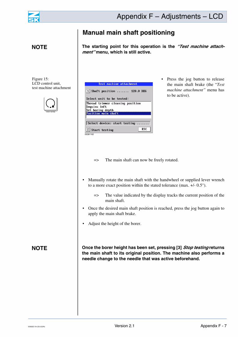
Manual main shaft positioning
=> The main shaft can now be freely rotated.
• Manually rotate the main shaft with the handwheel or supplied lever wrenchto a more exact position within the stated tolerance (max. +/- 0.5°).
=> The value indicated by the display tracks the current position of themain shaft.
• Once the desired main shaft position is reached, press the jog button again toapply the main shaft brake.
• Adjust the height of the borer.
NOTE The starting point for this operation is the “Test machine attach-ment” menu, which is still active.
Figure 15: LCD control unit,test machine attachment
• Press the jog button to releasethe main shaft brake (the “Testmachine attachment” menu hasto be active).
00013039
00381162
NOTE Once the borer height has been set, pressing [3] Stop testing returnsthe main shaft to its original position. The machine also performs aneedle change to the needle that was active beforehand.
00363i21.fm 25.6.02/Kx Version 2.1 Appendix F - 7
Appendix F – Adjustments – LCD
Main shaft brake
The machine is braked by an electromagnet integrated in the main motor whenstationary and disconnected from the power supply (main shaft brake). For somemaintenance purposes the main shaft brake has to be released when the machineis stationary. The brake is released electromagnetically; it is operated and con-trolled by functions that form part of the machine control software.
Releasing/engaging brake
For adjusting and maintenance work the brake can be deactivated and activatedagain manually by way of the control.
• Stop the machine.
NOTE The full user interface of the machine control has to be enabled to per-form this maintenance task. If the interface is protected by a password,you need to know what the password is.
NOTE When disconnected from the power supply, the machine is braked asa general rule and the shaft cannot be rotated with the handwheel.
DANGERDepending on the position in which it stops, the machine may runforward or back a little when the brake is released.
Before the brake is released, it is essential to ensure that nobodyis within the operating range of needles, rotary hooks or, in caseprotective covers have been removed, rotating drive elements.
Appendix F - 8 Version 2.1 00363i21.fm 25.6.02/Kx
Appendix F – Adjustments – LCD
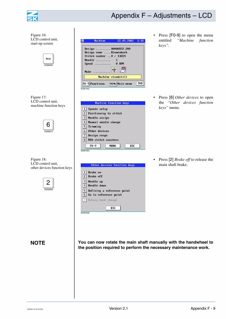
Figure 16: LCD control unit,start-up screen
• Press [F0-9] to open the menuentitled “Machine functionkeys”.
Figure 17: LCD control unit,machine function keys
• Press [6] Other devices to openthe “Other devices functionkeys” menu.
Figure 18: LCD control unit,other devices function keys
• Press [2] Brake off to release themain shaft brake.
00380830
F0-9
00381002
600380812
00381600
200380808
00381608
NOTE You can now rotate the main shaft manually with the handwheel tothe position required to perform the necessary maintenance work.
00363i21.fm 25.6.02/Kx Version 2.1 Appendix F - 9
Appendix F – Adjustments – LCD
• Once you have finished the maintenance work, press [1] Brake on to engagethe main shaft brake once again.1
00380808
• Press [ESC] twice to return to the main screen of the control.ESC
00380818
2x
Appendix F - 10 Version 2.1 00363i21.fm 25.6.02/Kx
Appendix F – Adjustments – TFT
Appendix F – Adjustments – TFT
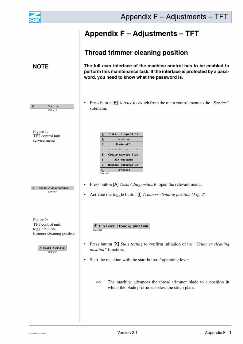
Thread trimmer cleaning position
=> The machine advances the thread trimmer blade to a position inwhich the blade protrudes below the stitch plate.
NOTE The full user interface of the machine control has to be enabled toperform this maintenance task. If the interface is protected by a pass-word, you need to know what the password is.
• Press button [E] Service to switch from the main control menu to the “Service”submenu.
00461015
Figure 1: TFT control unit,service menu
00461050
• Press button [A] Tests / diagnostics to open the relevant menu.
• Activate the toggle button [I] Trimmer cleaning position (Fig. 2).00461051
Figure 2: TFT control unit,toggle button,trimmer cleaning position
00461619
• Press button [X] Start testing to confirm initiation of the “Trimmer cleaningposition” function.
• Start the machine with the start button / operating lever.
00461597
00025i21.fm 25.6.02/Kx Version 2.1 Appendix F - 1
Appendix F – Adjustments – TFT
• Clean the thread trimmer blade with compressed air.
=> The machine moves the thread trimmer blade back to its restposition.
• Press [W] Stop testing to terminate the “Trimmer cleaning position” function.
00461598
Appendix F - 2 Version 2.1 00025i21.fm 25.6.02/Kx
Appendix F – Adjustments – TFT
Adjusting boring depth
Main shaft positioning
NOTE The full user interface of the machine control has to be enabled to per-form this maintenance task. If the interface is protected by a password,you need to know what the password is.
• Press button [E] Service to switch from the main control menu to the “Service”submenu.
00461015
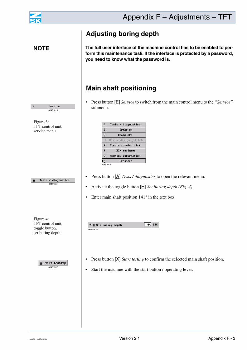
Figure 3: TFT control unit,service menu
00461015
• Press button [A] Tests / diagnostics to open the relevant menu.
• Activate the toggle button [H] Set boring depth (Fig. 4).
• Enter main shaft position 141° in the text box.
00461051
Figure 4: TFT control unit,toggle button,set boring depth
00461618
• Press button [X] Start testing to confirm the selected main shaft position.
• Start the machine with the start button / operating lever. 00461597
00025i21.fm 25.6.02/Kx Version 2.1 Appendix F - 3
Appendix F – Adjustments – TFT
=> The machine executes an automatic needle change to needle 3.
=> The main shaft moves to the desired position.
=> Once the desired shaft position is reached, the machine is automati-cally braked.
=> The selected main shaft position, 141°, appears at the top right of thescreen.
• Adjust the height of the borer.
NOTE The value that appears in the display must be within max. +/- 0.5° ofthe main shaft position that you entered. If the value is outside thistolerance (this can occur with the larger multi-head embroidery ma-chines), the position of the main shaft has to be adjusted manually.It may be possible to obtain the correct main shaft position by press-ing [W] Stop testing and then [X] Start testing.
Appendix F - 4 Version 2.1 00025i21.fm 25.6.02/Kx
Appendix F – Adjustments – TFT
Manual main shaft positioning
• Manually rotate the main shaft with the handwheel or supplied lever wrenchto a more exact position within the stated tolerance.
=> The value indicated by the display tracks the current position of themain shaft.
• Once the desired main shaft position is reached, press the jog button again toapply the main shaft brake.
• Adjust the height of the borer.
NOTE The starting point for this operation is the “Tests / diagnostics”menu, which is still active.
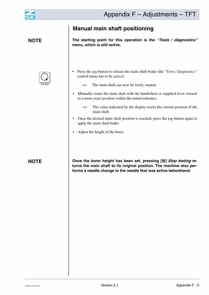
• Press the jog button to release the main shaft brake (the “Tests / diagnostics”control menu has to be active).
=> The main shaft can now be freely rotated. 00013039
NOTE Once the borer height has been set, pressing [W] Stop testing re-turns the main shaft to its original position. The machine also per-forms a needle change to the needle that was active beforehand.
00025i21.fm 25.6.02/Kx Version 2.1 Appendix F - 5
Appendix F – Adjustments – TFT
Main shaft brake
The machine is braked by an electromagnet integrated in the main motor whenstationary and disconnected from the power supply (main shaft brake). For somemaintenance purposes the main shaft brake has to be released when the machineis stationary. The brake is released electromagnetically; it is operated and con-trolled by functions that form part of the machine control software.
Releasing/engaging brake
For adjusting and maintenance work the brake can be deactivated and activatedagain manually by way of the control.
• Stop the machine.
NOTE The full user interface of the machine control has to be enabled to per-form this maintenance task. If the interface is protected by a password,you need to know what the password is.
NOTE When disconnected from the power supply, the machine is braked asa general rule and the shaft cannot be rotated with the handwheel.
DANGERDepending on the position in which it stops, the machine may runforward or back a little when the brake is released.
Before the brake is released, it is essential to ensure that nobodyis within the operating range of needles, rotary hooks or, in caseprotective covers have been removed, rotating drive elements.
Appendix F - 6 Version 2.1 00025i21.fm 25.6.02/Kx
Appendix F – Adjustments – TFT
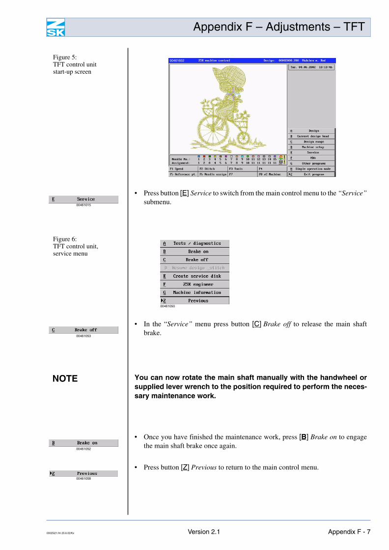
Figure 5: TFT control unitstart-up screen
00461602
• Press button [E] Service to switch from the main control menu to the “Service”submenu.
00461015
Figure 6: TFT control unit,service menu
00461050
• In the “Service” menu press button [C] Brake off to release the main shaftbrake.
00461053
NOTE You can now rotate the main shaft manually with the handwheel orsupplied lever wrench to the position required to perform the neces-sary maintenance work.
• Once you have finished the maintenance work, press [B] Brake on to engagethe main shaft brake once again.
00461052
• Press button [Z] Previous to return to the main control menu.