MV electrical network management Easergy range Flair 23DM Communicating fault passage indicators For all neutral arrangement system Voltage detection relay Modbus communication Appendix to the user's manual
Transcript
MV electrical network management
Easergy range
Flair 23DM Communicating fault passage indicators For all neutral arrangement system Voltage detection relay
Modbus communication Appendix to the user's manual
Flair 23DM Summary
2 NT00337-EN-02
1 PRESENTATION ......................................................................................................................................... 3 2 COMMISSIONING AND DIAGNOSIS ......................................................................................................... 5
2.1 AUTOMATIC ADAPTATION OF THE CONFIGURATION: AUTO-MODE ...................................................................... 6 2.2 ACCESS TO DATA ........................................................................................................................................... 7 2.3 LIST OF ADDRESS ZONES ............................................................................................................................... 8 2.4 DATA CODING ................................................................................................................................................ 9 2.5 SYNCHRONIZATION, IDENTIFICATION ZONE ..................................................................................................... 10 2.6 READING OF FLAIR 23DM IDENTIFICATION .................................................................................................... 12 2.7 MEASUREMENT AND COUNTERS ZONE ........................................................................................................... 14 2.8 REMOTE CONTROL ZONE ............................................................................................................................. 16 2.9 REMOTE CONTROL ORDER AND STATUS ZONE .............................................................................................. 18 2.10 TIME-TAGGED EVENTS ............................................................................................................................. 20 2.11 ACCESS TO REMOTE SETTINGS ................................................................................................................. 24 2.12 DATE AND TIME-SETTING AND SYNCHRONIZATION ..................................................................................... 27 2.13 MANAGING THE DATE AND TIME USING FUNCTION 43 ................................................................................ 29
Flair 23DM Presentation
NT00337-EN-02 3
1 Presentation The Flair 23DM has a communication port. Modbus communication allows Flair 23DM relays to be connected to a supervisor or any other device with a master Modbus communication port. Flair 23DM is always the slave. Accessible data: Modbus communication can be used to perform functions remotely such as: Reading of measurements, counters and diagnosis Reading of status conditions and remote indications Transfer of time-tagged events Reading of Flair 23DM identification Time-setting and synchronization Reading of settings Remote settings when these have been enabled Transmission of remote controls Modbus protocol principle: The Modbus protocol is used to exchange data by means of a request-response type mechanism between one station called the master and N slaves. Exchange initialization (sending the request) is always initiated by the master. The slave (Flair 23DM) can only respond to a request sent to it. When the network hardware infrastructure allows, several slaves can be connected to the same master. The request contains a slave number (address) to identify which is the destination. This number must be unique. Slaves that are not destinations ignore the request received. Modbus Frame structure: Each exchanged frame consists of a maximum of 255 bytes divided as follows (any frame with an error in format, parity, CRC 16, etc. is ignored): Slave Number Function Data or Sub-Function Code Control Word 1 byte 1 byte n bytes 2 bytes Request destination 0: broadcast (all) 1...247 (unique)
Refer to the next section
Request or response data (addresses/bit or word values, number of bits/bytes/data words) Sub-function code
CRC 16 (for detection of transmission errors)
The first two fields in the response are usually identical to those in the request. Modbus Functions Supported The Flair 23DM Modbus protocol is a subset of the Modbus RTU protocol: Data exchange functions
o 1: read n output bits o 2: read n input bits o 3: read n output words o 4: read n input words o 5: write 1 bit o 6: write 1 word o 15: write n bits o 16: write n consecutive words
Flair 23DM Presentation
4 NT00337-EN-02
Communication management functions
o 8: read Modbus diagnosis counters o 11: read Modbus event counter o 43 with sub-function 14: read identification o 43 with sub-function 15: read date and time o 43 with sub-function 16: write date and time
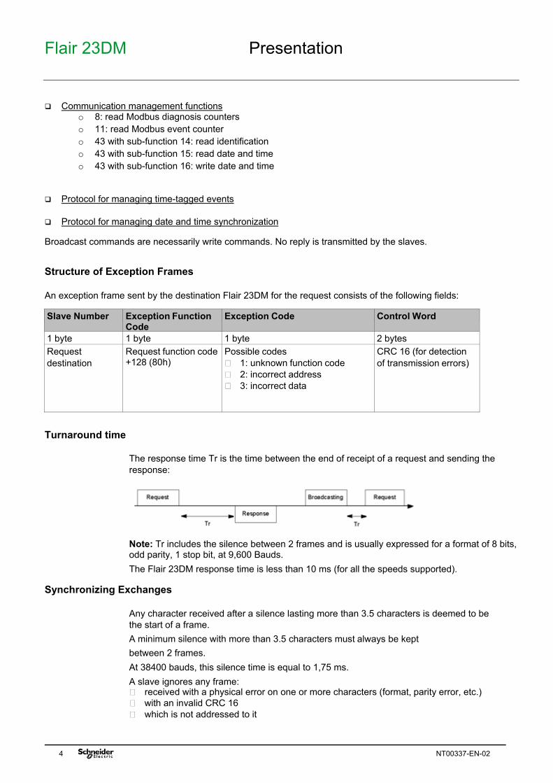
Protocol for managing time-tagged events Protocol for managing date and time synchronization Broadcast commands are necessarily write commands. No reply is transmitted by the slaves. Structure of Exception Frames An exception frame sent by the destination Flair 23DM for the request consists of the following fields: Slave Number Exception Function
Code Exception Code Control Word
1 byte 1 byte 1 byte 2 bytes Request destination
Request function code +128 (80h)
Possible codes 1: unknown function code 2: incorrect address 3: incorrect data
CRC 16 (for detection of transmission errors)
Turnaround time
The response time Tr is the time between the end of receipt of a request and sending the response:
Note: Tr includes the silence between 2 frames and is usually expressed for a format of 8 bits, odd parity, 1 stop bit, at 9,600 Bauds. The Flair 23DM response time is less than 10 ms (for all the speeds supported).
Synchronizing Exchanges
Any character received after a silence lasting more than 3.5 characters is deemed to be the start of a frame. A minimum silence with more than 3.5 characters must always be kept between 2 frames. At 38400 bauds, this silence time is equal to 1,75 ms. A slave ignores any frame: received with a physical error on one or more characters (format, parity error, etc.) with an invalid CRC 16 which is not addressed to it
Flair 23DM Commissioning and diagnosis
NT00337-EN-02 5
2 Commissioning and diagnosis Modbus protocol parameters
Parameters on HMI
Designation Authorized values Display on HMI
Default value
Cubn Cubicle number 0 (the Modbus address is configurable manually) 1…29 (the Modbus address is proposed automatically depending to the cubicle number defined)
nonE 1…29
0
Addr Modbus address Modbus
1...247 (the Modbus address, configured automatically from the Cubicle number value, is defined as follow: @ = 33+ 5x(CubicleNb-1). The Modbus address can be changed manually, if theone proposed automatically is not appropriate. In this case, modification of the address changes automatically the Cubicle number to 0.
OFF: Remote settings not enabled ON: Remote settings enabled
OFF On
ON
SbO Selection before execution
OFF: Remote control in direct mode ON: Remote control in SBO mode (Selection Before Execution)
OFF On
OFF
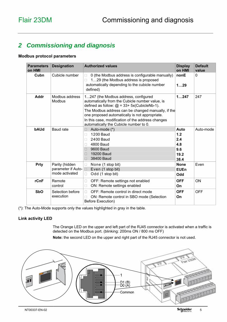
(*): The Auto-Mode supports only the values highlighted in gray in the table. Link activity LED
The Orange LED on the upper and left part of the RJ45 connector is activated when a traffic is detected on the Modbus port. (blinking: 200ms ON / 800 ms OFF) Note: the second LED on the upper and right part of the RJ45 connector is not used.
Flair 23DM Auto-adaptation of the configuration
6 NT00337-EN-02
Modbus Link Diagnosis
To check that the link is operating correctly, the user can refer to: 1. the link activity LED, on the RJ45 connector of Modbus RS485 link 2. the Modbus diagnosis counters and the Modbus event counter
2.1 Automatic Adaptation of the Configuration: Auto-mode Presentation
The "Auto-mode" mechanism is a device for simplifying the Modbus device configuration. Its algorithm allows a Flair 23DM (slave) to automatically detect the configuration used on the Modbus link to which it is connected.
Operation The algorithm in the "Auto-mode" mechanism automatically detects the network parameters by testing the available transmission speeds and parities. The Modbus master must send at least 13 frames on the Modbus network before the "Auto-mode" mechanism algorithm works. There must be enough traffic on the link before the Flair 23DM can be deemed to be absent or in faulty status. The detection of network parameters begins firstly at maximum speed (38400 baud). Then, if detection is not conclusive, detection continues with the next lower speed (e.g. 19200 baud) and so on in order to detect the suitable speed. The detected network parameters are deemed to be valid after correct reception of three different frames. In this case, the product will use the detected parameters and will save them in non-volatile memory. Note: If the Modbus configuration set on the Flair 23DM is modified manually by the installer to fix the speed to a specific value, the "Auto-mode" mechanism will be disabled. The automatic search of network parameters will be only active again if Auto-mode is re-activated manually. Note: On restarting the Flair 23DM, the saved Modbus parameters on the product will be memorized. In the event of a fault on restarting, the search phase will be disabled. The research phase is restarted from the last speed memorized by the Auto-mode and it will validates again this speed if 7 valid frames are detected at that speed. Thereafter, the research phase is restarted after 7 successive faults detected during operation. Moreover, it is possible to disable the "Auto-mode" mechanism and then manually set the Modbus network parameters
Detectable Configurations The 3 configurations supported by the algorithm are as follows: “Even” parity, 1 stop bit “Odd” parity, 1 stop bit no parity, 1 stop bit associated with the following 3 transmission speeds: 9,600 Baud 19,200 Baud 38,400 Baud i.e. a total of 9 detectable configurations. Note: It is recommended to avoid the format "no parity". When operating on a network "no parity", the Flair23DM select the format "no parity, 1 stop bit" whatever the number of stop bits used by the Master.
Flair 23DM Access to data
NT00337-EN-02 7
2.2 Access to data Addressing a word
All Flair 23DM data that can be accessed by Modbus communication is organized into 16-bit words. Each word is identified by its address, coded on 16 bits, i.e. from 0 to 65535 (FFFFh).
Addressing a bit
Some data can also be accessed in the form of a bit. The bit address is then deducted from the word address by: Bit address = (word address x 16) + bit number (0...15). Example: Address word 3072 (0C00h) bit 0 address = C000h bit 14 address = C00Eh
Undefined Addresses
Only addresses defined in this document should be used. If other addresses are used, the Flair 23DM can either respond with an exception message, or provide non-significant data.
Access mode
The data are direct-access: they are permanently identified by their Modbus address. These can be reached in a single read or write operation, applying to all or part of the relevant zone. In Flair 23DM, all zones are accessed directly, however for some zones, such as those for time-tagged events, a particular protocol can be used to optimize exchanges with the supervisor. This protocol is specified in the relevant zones.
Flair 23DM List of address zones
8 NT00337-EN-02
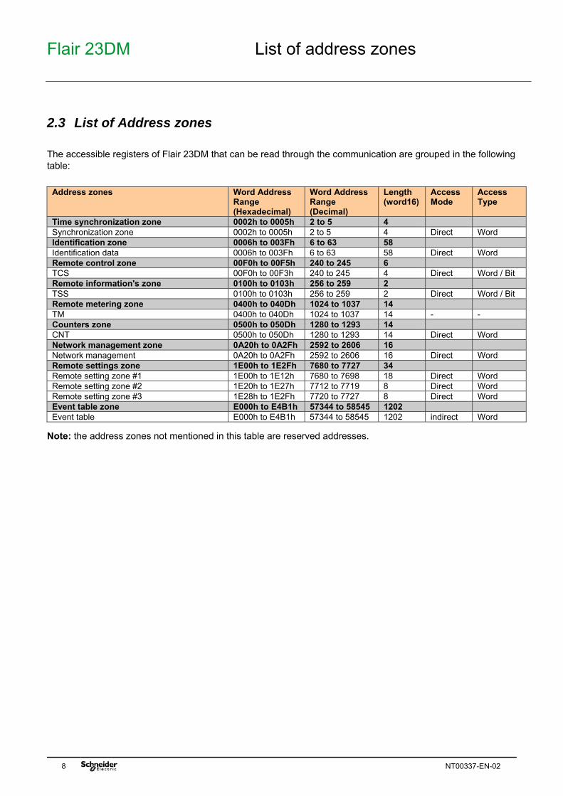
2.3 List of Address zones The accessible registers of Flair 23DM that can be read through the communication are grouped in the following table:
Address zones Word Address
Range (Hexadecimal)
Word Address Range (Decimal)
Length (word16)
Access Mode
Access Type
Time synchronization zone 0002h to 0005h 2 to 5 4 Synchronization zone 0002h to 0005h 2 to 5 4 Direct Word Identification zone 0006h to 003Fh 6 to 63 58 Identification data 0006h to 003Fh 6 to 63 58 Direct Word Remote control zone 00F0h to 00F5h 240 to 245 6 TCS 00F0h to 00F3h 240 to 245 4 Direct Word / Bit Remote information's zone 0100h to 0103h 256 to 259 2 TSS 0100h to 0103h 256 to 259 2 Direct Word / Bit Remote metering zone 0400h to 040Dh 1024 to 1037 14 TM 0400h to 040Dh 1024 to 1037 14 - - Counters zone 0500h to 050Dh 1280 to 1293 14 CNT 0500h to 050Dh 1280 to 1293 14 Direct Word Network management zone 0A20h to 0A2Fh 2592 to 2606 16 Network management 0A20h to 0A2Fh 2592 to 2606 16 Direct Word Remote settings zone 1E00h to 1E2Fh 7680 to 7727 34 Remote setting zone #1 1E00h to 1E12h 7680 to 7698 18 Direct Word Remote setting zone #2 1E20h to 1E27h 7712 to 7719 8 Direct Word Remote setting zone #3 1E28h to 1E2Fh 7720 to 7727 8 Direct Word Event table zone E000h to E4B1h 57344 to 58545 1202 Event table E000h to E4B1h 57344 to 58545 1202 indirect Word
Note: the address zones not mentioned in this table are reserved addresses.
Flair 23DM Data coding
NT00337-EN-02 9
2.4 Data coding Format used
Apart from exceptions mentioned in the text, Flair 23DM data is coded in one of the formats below: 32S: signed value, coded on 32 bits 16S: signed value, coded on 16 bits B: bit or set of bits ASCII nc: string of n characters in ASCII code IEC: time coding format on 4 words conforming to IEC 60870-5-4.
32S Format
Flair 2xD does not support 32-bit measurements. This format is only valid for the counters. In 32S format, the first word is the most significant. An incalculable value, whether invalid or outside the authorized range, is fixed at 2147483648 (80000000h).
16S Format
An incalculable value, whether invalid or outside the authorized range, is fixed at 32768 (8000h).
ASCII Format
ASCII format is used to code the identification strings for a Flair 23DM. When the ASCII strings do not fill up the field entirely, they are completed with null bytes. The first character occupies the most significant byte on the first word, the second the least significant byte on the first word, etc.
IEC Format
The date and time are coded on 4 words, in IEC 60870-5-4 format (bits at 0 in the table are not used: they are always read at 0 and ignored in write mode): Bit 15 14 13 12 11 10 9 8 7 6 5 4 3 2 1 0 Word Reserved (0 in read mode, variable in write mode) 0 Year (0...99) Word 0 0 0 0 Month (1...12) 0 0 0 Day (1...31) Word 0 0 0 Hour (0...23) 0 0 Minutes (0...59) Word Milliseconds (0...59,999) Year - 1 byte for years: varies from 0 to 127 years. (1/1/2000 to 31/12/2127). Month - (4 bits) for months: varies from 1 to 12. Day – Day of Month, (5 bits): varies from 1 to 31. Hour - 1 byte for hours: varies from 0 to 23. Minute - 1 byte for minutes: varies from 0 to 59. Millisecond - 2 bytes for milliseconds: varies from 0 to 59999.
Flair 23DM Synchronization, identification zone
10 NT00337-EN-02
2.5 Synchronization, identification zone Introduction
Synchronization, identification, metering, network diagnosis and test zones are accessed directly and do not contain any events. For each zone, a table contains the following information: description of the addresses in the zone codes for Modbus functions that can be used in read mode codes for Modbus functions that can be used in write mode if necessary, the formats and resolution of the stored data
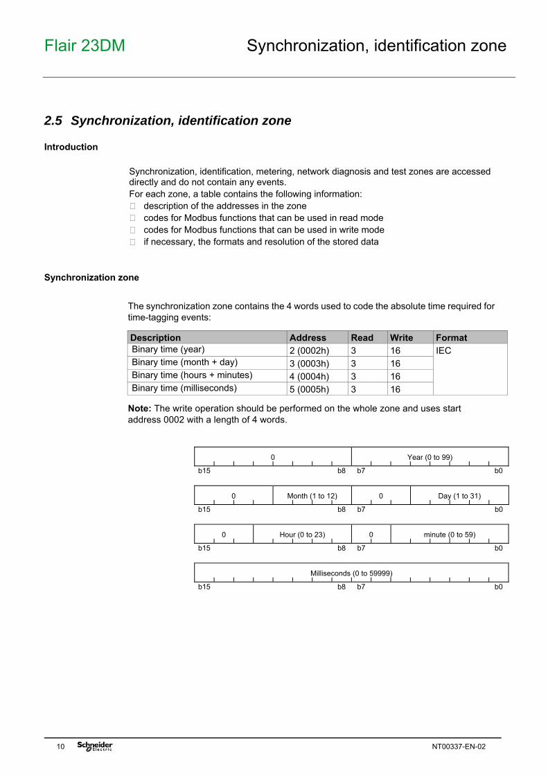
Synchronization zone The synchronization zone contains the 4 words used to code the absolute time required for time-tagging events:
Description Address Read Write Format Binary time (year) 2 (0002h) 3 16 IEC Binary time (month + day) 3 (0003h) 3 16 Binary time (hours + minutes) 4 (0004h) 3 16 Binary time (milliseconds) 5 (0005h) 3 16
Note: The write operation should be performed on the whole zone and uses start address 0002 with a length of 4 words.
0 Year (0 to 99)
b15 b8 b7 b0
0 Month (1 to 12) 0 Day (1 to 31)
b15 b8 b7 b0
0 Hour (0 to 23) 0 minute (0 to 59)
b15 b8 b7 b0
Milliseconds (0 to 59999)
b15 b8 b7 b0
Flair 23DM Synchronization, identification zone
NT00337-EN-02 11
SSSS : Seq Number within order line OOOOOO : Order number
Identification zone
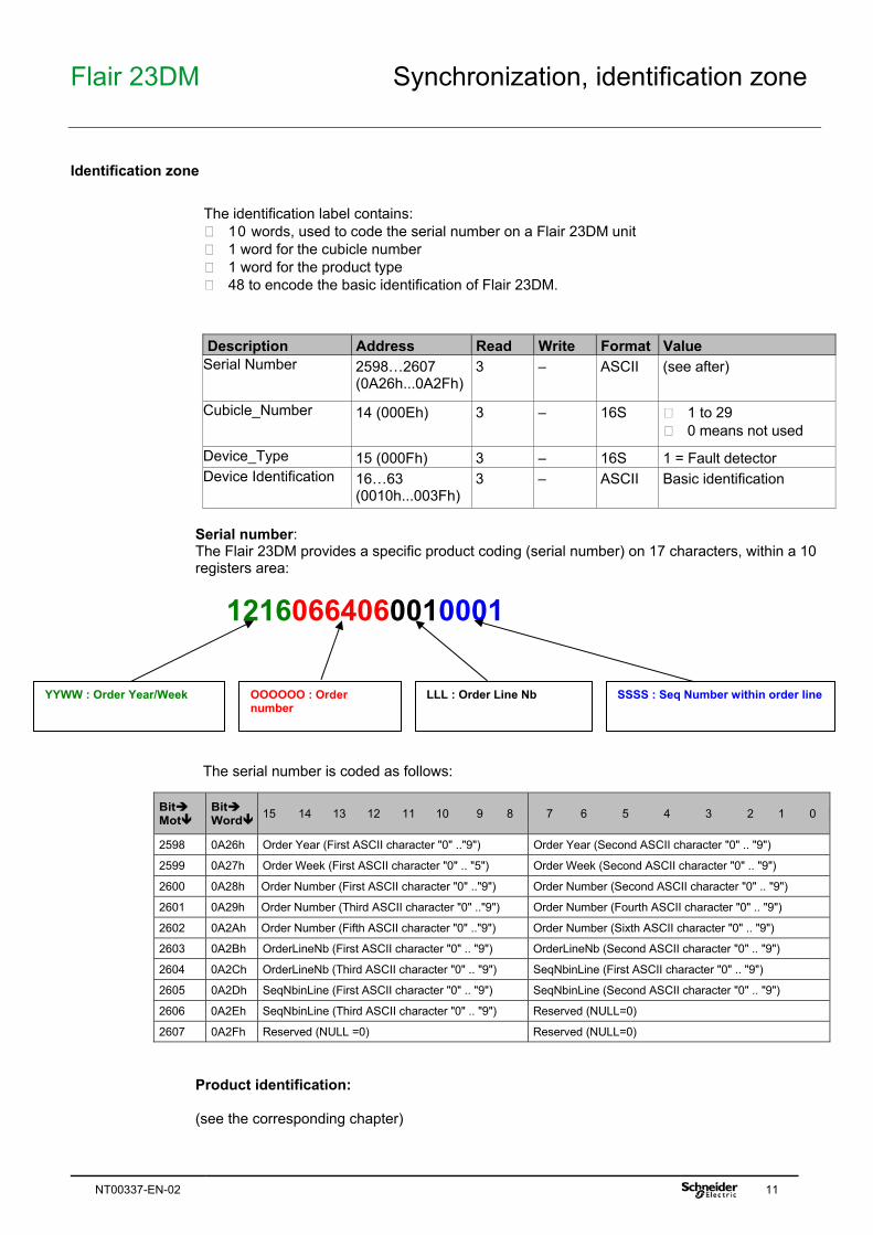
The identification label contains: 10 words, used to code the serial number on a Flair 23DM unit 1 word for the cubicle number 1 word for the product type 48 to encode the basic identification of Flair 23DM.
Description Address Read Write Format Value
Serial Number 2598…2607 (0A26h...0A2Fh)
3 — ASCII (see after)
Cubicle_Number 14 (000Eh) 3 — 16S 1 to 29 0 means not used
Product identification: (see the corresponding chapter)
YYWW : Order Year/Week LLL : Order Line Nb
Flair 23DM Reading of Flair 23DM identification
12 NT00337-EN-02
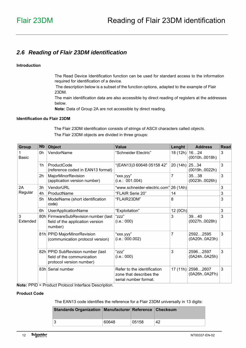
2.6 Reading of Flair 23DM identification Introduction
The Read Device Identification function can be used for standard access to the information required for identification of a device. The description below is a subset of the function options, adapted to the example of Flair 23DM. The main identification data are also accessible by direct reading of registers at the addresses below. Note: Data of Group 2A are not accessible by direct reading.
Identification du Flair 23DM
The Flair 23DM identification consists of strings of ASCII characters called objects. The Flair 23DM objects are divided in three groups:
The read identification request frame consists of the following fields:
Field Size (Bytes) Value Slave number 1 1...247 Function code 1 43 (2Bh) MEI type (sub-function code) 1 14 (0Eh) Read type 1 01 or 02 or 03 or 04 Not used 1 00 CRC16 2 Calculated
Response frame
The response frame consists of the following fields:
Field Size (Bytes) Value Slave number 1 1...247 Function code 1 43 (2Bh) MEI type (sub-function code) 1 14 (0Eh) Read type 1 01 or 02 or 03 or 04 Conformity level 1 131 (83h) Not used 1 00 Not used 1 00 Number of objects 1 n = 3, 7 or 11, according to the Read type field First object number 1 obj1 First object length 1 lg1 First object ASCII string lg1 txt1 ... ... ... nth object number 1 objn nth object length 1 lgn nth object ASCII string lgn txtn CRC16 2 Calculated
Exception frame
If an error occurs while processing the request, the Flair 23DM sends an exception frame, consisting of the following fields:
Field Size (Bytes) Value Slave number 1 1...247 Function code increased by 80h 1 171 (ABh) MEI type (sub-function code) 1 14 (0Eh) or other if MEI type received is
incorrect.
Exception code 1 01: MEI type received is incorrect (≠ 14). 02: in cases of individual access (read code 04), if the requested object does not exist. 03: incorrect data (frame length incorrect or read code invalid).
CRC16 2 Calculated
Flair 23DM Measurement and counters zone
14 NT00337-EN-02
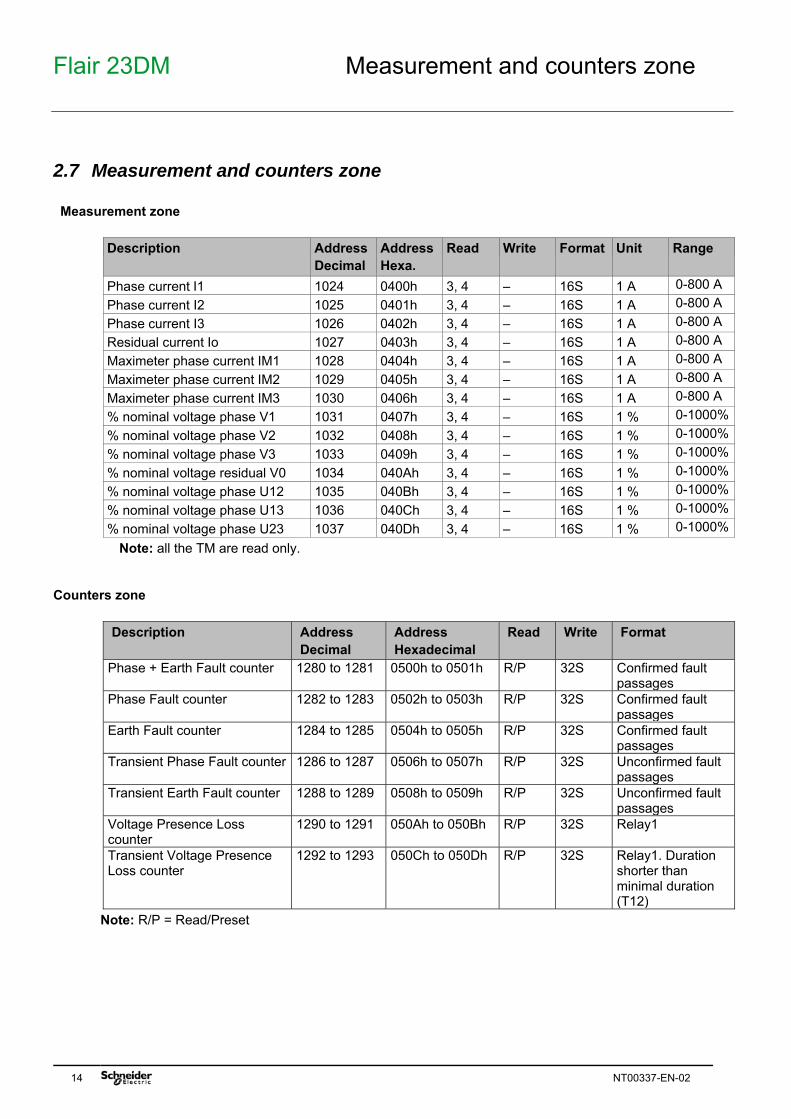
2.7 Measurement and counters zone Measurement zone
Description Address
Decimal Address Hexa.
Read Write Format Unit Range
Phase current I1 1024 0400h 3, 4 — 16S 1 A 0-800 A Phase current I2 1025 0401h 3, 4 — 16S 1 A 0-800 A Phase current I3 1026 0402h 3, 4 — 16S 1 A 0-800 A Residual current Io 1027 0403h 3, 4 — 16S 1 A 0-800 A Maximeter phase current IM1 1028 0404h 3, 4 — 16S 1 A 0-800 A Maximeter phase current IM2 1029 0405h 3, 4 — 16S 1 A 0-800 A Maximeter phase current IM3 1030 0406h 3, 4 — 16S 1 A 0-800 A % nominal voltage phase V1 1031 0407h 3, 4 — 16S 1 % 0-1000% % nominal voltage phase V2 1032 0408h 3, 4 — 16S 1 % 0-1000% % nominal voltage phase V3 1033 0409h 3, 4 — 16S 1 % 0-1000% % nominal voltage residual V0 1034 040Ah 3, 4 — 16S 1 % 0-1000% % nominal voltage phase U12 1035 040Bh 3, 4 — 16S 1 % 0-1000% % nominal voltage phase U13 1036 040Ch 3, 4 — 16S 1 % 0-1000% % nominal voltage phase U23 1037 040Dh 3, 4 — 16S 1 % 0-1000%
Note: all the TM are read only. Counters zone
Description Address Decimal
Address Hexadecimal
Read Write Format
Phase + Earth Fault counter 1280 to 1281 0500h to 0501h R/P 32S Confirmed fault passages
Phase Fault counter 1282 to 1283 0502h to 0503h R/P 32S Confirmed fault passages
Earth Fault counter 1284 to 1285 0504h to 0505h R/P 32S Confirmed fault passages
Transient Phase Fault counter 1286 to 1287 0506h to 0507h R/P 32S Unconfirmed fault passages
Transient Earth Fault counter 1288 to 1289 0508h to 0509h R/P 32S Unconfirmed fault passages
Voltage Presence Loss counter
1290 to 1291 050Ah to 050Bh R/P 32S Relay1
Transient Voltage Presence Loss counter
1292 to 1293 050Ch to 050Dh R/P 32S Relay1. Duration shorter than minimal duration (T12)
Note: R/P = Read/Preset
Flair 23DM Measurement and counters zone
NT00337-EN-02 15
Counters for Modbus diagnosis The diagnosis counters are read using function 8 and sub-codes 000Bh to 0012h depending on the counter. Function 8 can also be used in echo mode (sub-code 0000h): Function Frame Sent Frame Expected in Response 8 in echo mode 01 08 0000 1234 ED7C 01 08 0000 1234 ED7C Event counter is read using function 11. Also accessible as manufacturer data by direct register access: Description Address Read Write Format Reset counters 62464 (F400h) - 6, 16 1 = reset Bus Message Count 62465 (F401h) 3 Bus Communication Error Count 62466 (F402h) 3 Slave Exception Error Count 62467 (F403h) 3 Slave Message Count 62468 (F404h) 3 Slave No Response Count 62469 (F405h) 3 Idle count 62470 (F406h) 3 If no
activity > 80ms
May be displayed also locally on the product by the following operation: - 5s press on ESC button => the Flair 23DM displays "Fact", blinking - press left button "" within 3s (if not will the product will be reseted) - navigate to reach "CPT" menu - use the " " button to freeze/unfreeze circular display of counter values - use Test/Reset button during counter display to reset them (other Reset can be done via communication or general reset of product
Resetting counters
The counters are reset to 0 in the following cases: when they reach the maximum value 65535 (FFFFh) when they are reset by a Modbus command (function 8, sub-code 000Ah) during a power failure of Flair 23DM.
Flair 23DM Remote control zone
16 NT00337-EN-02
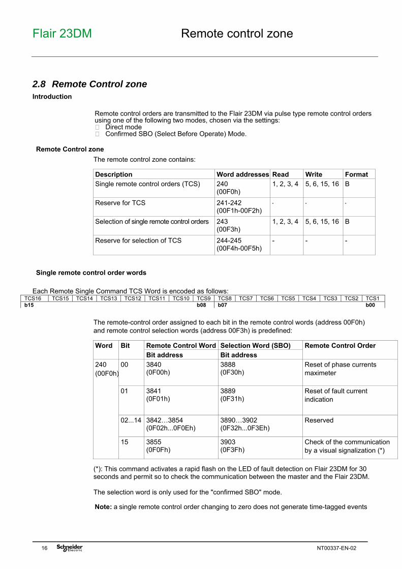
2.8 Remote Control zone Introduction
Remote control orders are transmitted to the Flair 23DM via pulse type remote control orders using one of the following two modes, chosen via the settings: Direct mode Confirmed SBO (Select Before Operate) Mode.
Remote Control zone
The remote control zone contains:
Description Word addresses Read Write Format Single remote control orders (TCS) 240
(00F0h) 1, 2, 3, 4 5, 6, 15, 16 B
Reserve for TCS 241-242 (00F1h-00F2h)
- - -
Selection of single remote control orders 243 (00F3h)
1, 2, 3, 4 5, 6, 15, 16 B
Reserve for selection of TCS 244-245 (00F4h-00F5h)
- - -
Single remote control order words
Each Remote Single Command TCS Word is encoded as follows:
The remote-control order assigned to each bit in the remote control words (address 00F0h) and remote control selection words (address 00F3h) is predefined:
Word Bit Remote Control Word Selection Word (SBO) Remote Control Order
Bit address Bit address 240 (00F0h)
00 3840 (0F00h)
3888 (0F30h)
Reset of phase currents maximeter
01 3841 (0F01h)
3889 (0F31h)
Reset of fault current indication
02...14 3842…3854 (0F02h...0F0Eh)
3890…3902 (0F32h...0F3Eh)
Reserved
15 3855 (0F0Fh)
3903 (0F3Fh)
Check of the communication by a visual signalization (*)
(*): This command activates a rapid flash on the LED of fault detection on Flair 23DM for 30 seconds and permit so to check the communication between the master and the Flair 23DM. The selection word is only used for the "confirmed SBO" mode. Note: a single remote control order changing to zero does not generate time-tagged events
Flair 23DM Remote control zone
NT00337-EN-02 17
Command rejection at communication level Remote command may be rejected at communication level with following reasons:
o exception 3 (Illegal data value) if remote command is inconsistent or in case of select/operate issue (not selected, timeout elapsed, …)
o exception 2 (Illegal Data Address) if requested command is not supported by the Flair 23DM o exception 6 (Slave Busy) if Flair 23DM is busy (command under execution). o
Direct mode
If remote control orders are configured in “direct” mode, the remote control order is executed immediately on writing to the remote control word. Resetting is performed by the control logic after the remote control order has been taken into account.
Confirmed SBO mode
The remote control order is executed in two steps: 1. Selection by the supervisor of the command to be sent by writing the bit in the remote
control selection word and checking the selection if necessary by re-reading this word. 2. Execution of the command to be sent by writing the bit in the remote control word. Note: when this mode is selected, it applies to all control orders. The remote control order is executed if the remote control selection word bit and the associated remote control word bit are set, both word bits are reset by the control logic after the remote control order has been taken into account. Deselection of the selection word bit occurs: if the supervisor deselects it by writing in the selection word if the supervisor selects (writes) a different bit from that already selected if the supervisor sets a bit in the remote control word that does not correspond to that
selected (in this case no remote control order will be executed) No remote control will be executed: if the corresponding order is not sent within a period of 30 seconds
Flair 23DM Remote control order and status zone
18 NT00337-EN-02
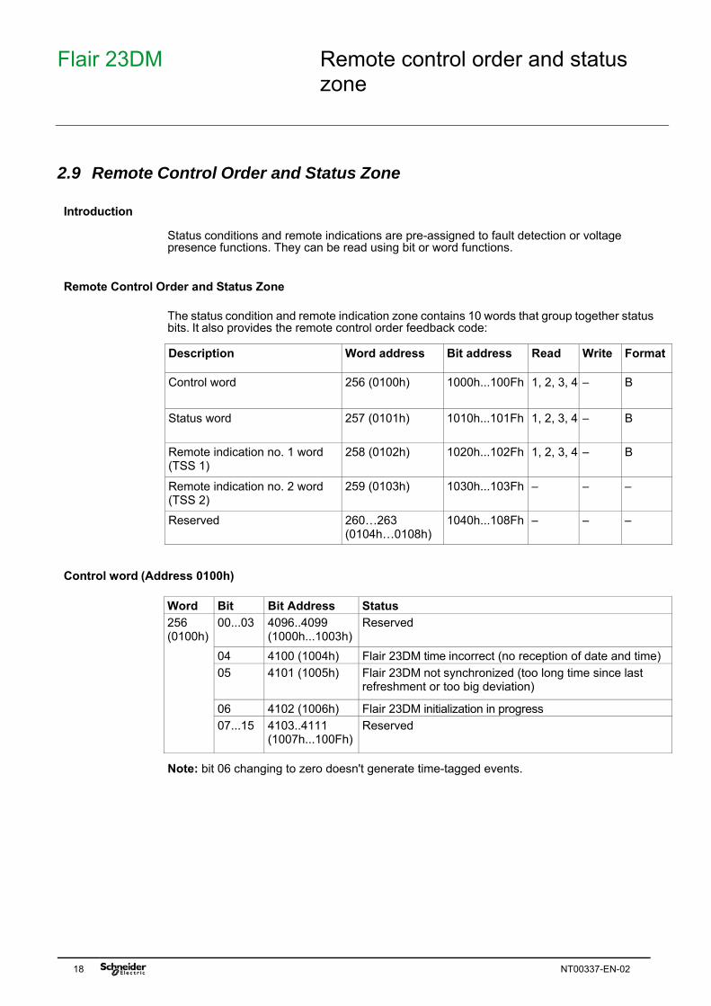
2.9 Remote Control Order and Status Zone Introduction
Status conditions and remote indications are pre-assigned to fault detection or voltage presence functions. They can be read using bit or word functions.
Remote Control Order and Status Zone
The status condition and remote indication zone contains 10 words that group together status bits. It also provides the remote control order feedback code:
Description Word address Bit address Read Write Format
Control word 256 (0100h) 1000h...100Fh 1, 2, 3, 4 — B
Status word 257 (0101h) 1010h...101Fh 1, 2, 3, 4 — B
Remote indication no. 1 word (TSS 1)
258 (0102h) 1020h...102Fh 1, 2, 3, 4 — B
Remote indication no. 2 word (TSS 2)
259 (0103h) 1030h...103Fh — — —
Reserved 260…263 (0104h…0108h)
1040h...108Fh — — —
Control word (Address 0100h)
Word Bit Bit Address Status 256 (0100h)
00...03 4096..4099 (1000h...1003h)
Reserved
04 4100 (1004h) Flair 23DM time incorrect (no reception of date and time) 05 4101 (1005h) Flair 23DM not synchronized (too long time since last
refreshment or too big deviation)
06 4102 (1006h) Flair 23DM initialization in progress 07...15 4103..4111
(1007h...100Fh) Reserved
Note: bit 06 changing to zero doesn't generate time-tagged events.
Flair 23DM Remote control order and status zone
NT00337-EN-02 19
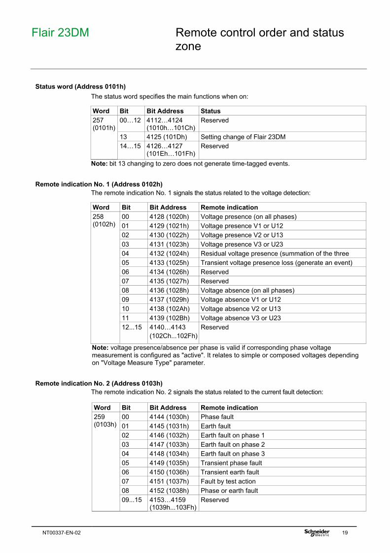
Status word (Address 0101h)
The status word specifies the main functions when on: Word Bit Bit Address Status 257 (0101h)
00…12 4112…4124 (1010h…101Ch)
Reserved
13 4125 (101Dh) Setting change of Flair 23DM 14…15 4126…4127
(101Eh…101Fh) Reserved
Note: bit 13 changing to zero does not generate time-tagged events.
Remote indication No. 1 (Address 0102h) The remote indication No. 1 signals the status related to the voltage detection: Word Bit Bit Address Remote indication 258 (0102h)
00 4128 (1020h) Voltage presence (on all phases) 01 4129 (1021h) Voltage presence V1 or U12 02 4130 (1022h) Voltage presence V2 or U13 03 4131 (1023h) Voltage presence V3 or U23 04 4132 (1024h) Residual voltage presence (summation of the three 05 4133 (1025h) Transient voltage presence loss (generate an event) 06 4134 (1026h) Reserved 07 4135 (1027h) Reserved 08 4136 (1028h) Voltage absence (on all phases) 09 4137 (1029h) Voltage absence V1 or U12 10 4138 (102Ah) Voltage absence V2 or U13 11 4139 (102Bh) Voltage absence V3 or U23 12...15 4140…4143
(102Ch...102Fh) Reserved
Note: voltage presence/absence per phase is valid if corresponding phase voltage measurement is configured as "active". It relates to simple or composed voltages depending on "Voltage Measure Type" parameter.
Remote indication No. 2 (Address 0103h) The remote indication No. 2 signals the status related to the current fault detection:
Word Bit Bit Address Remote indication 259 (0103h)
The Flair 23DM includes a time-tagged event mechanism so that its operation can be monitored using a supervisor. This data can be retrieved via the Modbus link. This data is volatile and will therefore be lost if the product is de-energized.
Event types
The Flair 23DM manages logic events, any change of state on Flair 23DM logic variable (bit in control, status or remote indication words). Each event is mainly characterized by: an identifier: Modbus address of associated data bit a value (for logic events, it is the direction of change) a date and time: the event is time-tagged (resolution: 1 ms)
Time-Tagging
Time-tagging of events uses the Flair 23DM internal clock. When an event is detected, the Flair 23DM’s current time is associated with it. During the initialization phase, the clock starts at “1st January 2000 00h 00min 0sec”. It will be re-synchronized to the current date and time after reception of the synchronization or on time setting. The chronology of detected events remains valid in all cases
Description of how to code an Event
An event is coded on 12 words with the following structure:
Word Information Coding 1 Event number Between 1 and 65535 2...5 Date and time of the
event In IEC 60870-5-4 format
6 (MSB) Number of associated events
0 (no secondary event associated with the Flair23DM events)
6 (LSB) Type of data Boolean (04h) 7 Event identifier Address of the associated data bit 8...11 Associated data Direction of the event:
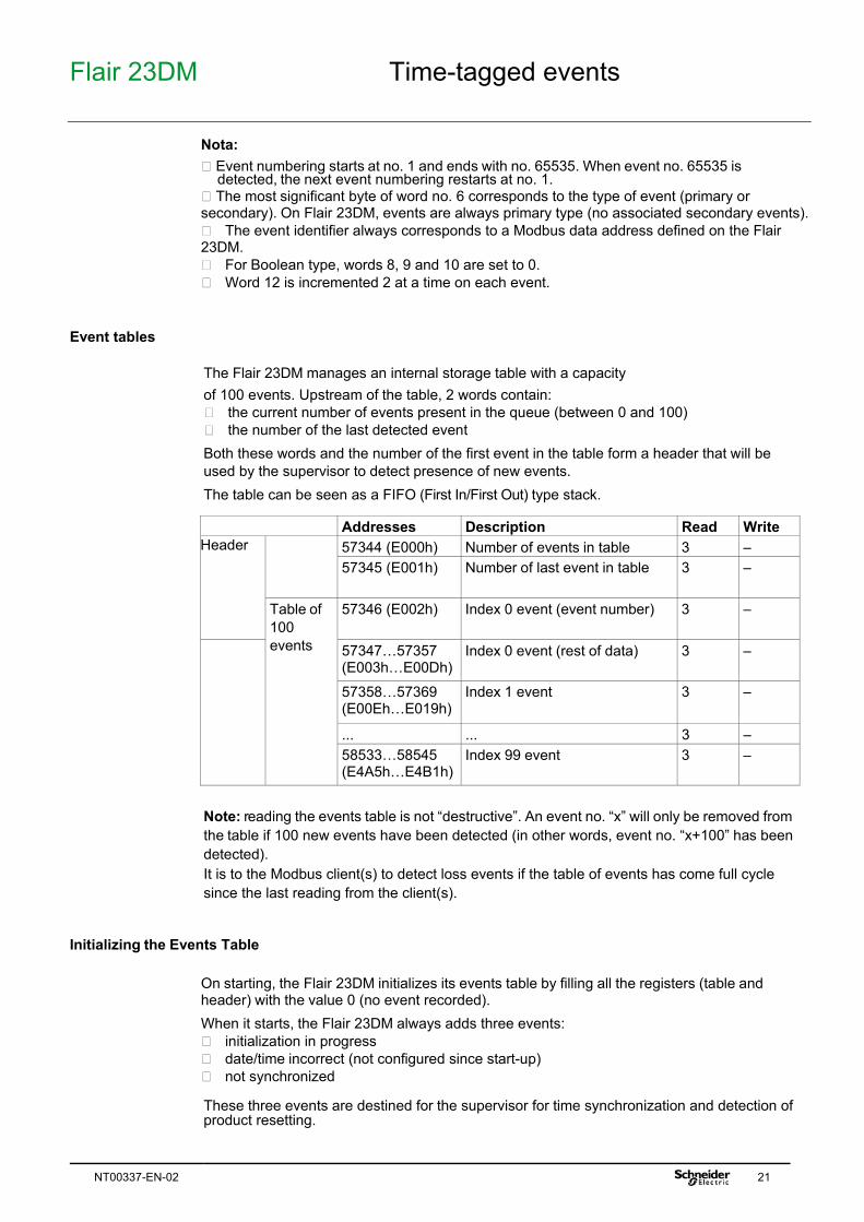
Nota: Event numbering starts at no. 1 and ends with no. 65535. When event no. 65535 is
detected, the next event numbering restarts at no. 1. The most significant byte of word no. 6 corresponds to the type of event (primary or secondary). On Flair 23DM, events are always primary type (no associated secondary events). The event identifier always corresponds to a Modbus data address defined on the Flair 23DM. For Boolean type, words 8, 9 and 10 are set to 0. Word 12 is incremented 2 at a time on each event.
Event tables
The Flair 23DM manages an internal storage table with a capacity of 100 events. Upstream of the table, 2 words contain: the current number of events present in the queue (between 0 and 100) the number of the last detected event Both these words and the number of the first event in the table form a header that will be used by the supervisor to detect presence of new events. The table can be seen as a FIFO (First In/First Out) type stack. Addresses Description Read Write Header 57344 (E000h) Number of events in table 3 —
57345 (E001h) Number of last event in table 3 —
Table of 100 events
57346 (E002h) Index 0 event (event number) 3 —
57347…57357 (E003h…E00Dh)
Index 0 event (rest of data) 3 —
57358…57369 (E00Eh…E019h)
Index 1 event 3 —
... ... 3 — 58533…58545 (E4A5h…E4B1h)
Index 99 event 3 —
Note: reading the events table is not “destructive”. An event no. “x” will only be removed from the table if 100 new events have been detected (in other words, event no. “x+100” has been detected). It is to the Modbus client(s) to detect loss events if the table of events has come full cycle since the last reading from the client(s).
Initializing the Events Table
On starting, the Flair 23DM initializes its events table by filling all the registers (table and header) with the value 0 (no event recorded). When it starts, the Flair 23DM always adds three events: initialization in progress date/time incorrect (not configured since start-up) not synchronized These three events are destined for the supervisor for time synchronization and detection of product resetting.
Flair 23DM Time-tagged events
22 NT00337-EN-02
Read sequence
The consultation protocol for time-tagged events includes a standard sequence that can be executed by a supervisor to detect and retrieve new events present on the Flair 23DM. This sequence is divided into two parts: detection of new events on the Flair 23DM reading of new events on the Flair 23DM Detection of new events on the Flair 23DM: new events are detected by periodic reading of the header in the time-tagged events zone (addresses E000h to E002h). If the “number of last event” in table changes between two header readings, one or more events have been added to the table. The supervisor can then read the new events. Read Previous Header (n-1) Read Current Header (n) Address Value Address Value 57344 (E000h) X 57344 (E000h) X 57345 (E001h) Y 57345 (E001h) Y 57346 (E002h) Z 57346 (E002h) Z Reading of new events on the Flair 23DM: based on values read in the headers, the supervisor can determine the Modbus register ranges to be read to obtain the new event data. The number of new events detected equals “Y’-Y”. The supervisor determines the position (index) in the table of the first and last new event starting from the event number stored at index 0 of the table (“Z’”). The Modbus register addresses associated with the new events can be deduced from the indexes: event start address = E002h + index * 12 event end address = E002h + (index + 1) * 12 - 1
Loss of Events
If the number of new events exceeds the table capacity, only the 100 most recent events will still be accessible. The oldest events will be lost forever. The supervisor is responsible for retrieving events from the Flair 23DM. It is up to him to adapt his consultation strategy to avoid the loss of events.
Flair 23DM Time-tagged events
NT00337-EN-02 23
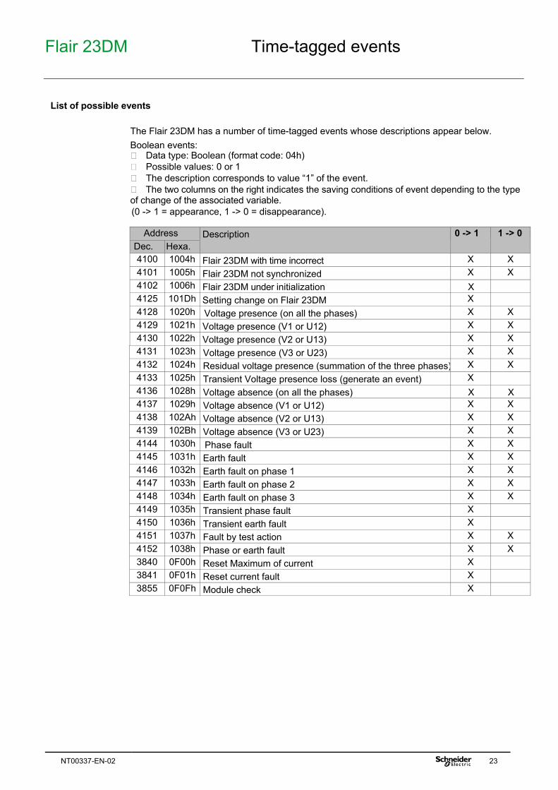
List of possible events
The Flair 23DM has a number of time-tagged events whose descriptions appear below. Boolean events: Data type: Boolean (format code: 04h) Possible values: 0 or 1 The description corresponds to value “1” of the event. The two columns on the right indicates the saving conditions of event depending to the type of change of the associated variable. (0 -> 1 = appearance, 1 -> 0 = disappearance).
Address Description 0 -> 1 1 -> 0
Dec. Hexa. 4100 1004h Flair 23DM with time incorrect X X 4101 1005h Flair 23DM not synchronized X X 4102 1006h Flair 23DM under initialization X 4125 101Dh Setting change on Flair 23DM X 4128 1020h Voltage presence (on all the phases) X X 4129 1021h Voltage presence (V1 or U12) X X 4130 1022h Voltage presence (V2 or U13) X X 4131 1023h Voltage presence (V3 or U23) X X 4132 1024h Residual voltage presence (summation of the three phases) X X 4133 1025h Transient Voltage presence loss (generate an event) X 4136 1028h Voltage absence (on all the phases) X X 4137 1029h Voltage absence (V1 or U12) X X 4138 102Ah Voltage absence (V2 or U13) X X 4139 102Bh Voltage absence (V3 or U23) X X 4144 1030h Phase fault X X 4145 1031h Earth fault X X 4146 1032h Earth fault on phase 1 X X 4147 1033h Earth fault on phase 2 X X 4148 1034h Earth fault on phase 3 X X 4149 1035h Transient phase fault X 4150 1036h Transient earth fault X 4151 1037h Fault by test action X X 4152 1038h Phase or earth fault X X 3840 0F00h Reset Maximum of current X 3841 0F01h Reset current fault X 3855 0F0Fh Module check X
Flair 23DM Access to remote settings
24 NT00337-EN-02
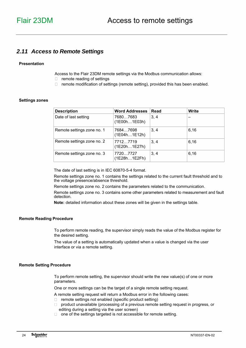
2.11 Access to Remote Settings Presentation
Access to the Flair 23DM remote settings via the Modbus communication allows: remote reading of settings remote modification of settings (remote setting), provided this has been enabled.
Settings zones
Description Word Addresses Read Write Date of last setting 7680…7683
(1E00h…1E03h) 3, 4 —
Remote settings zone no. 1 7684…7698 (1E04h…1E12h)
3, 4 6,16
Remote settings zone no. 2 7712…7719 (1E20h…1E27h)
3, 4 6,16
Remote settings zone no. 3 7720…7727 (1E28h…1E2Fh)
3, 4 6,16
The date of last setting is in IEC 60870-5-4 format. Remote settings zone no. 1 contains the settings related to the current fault threshold and to the voltage presence/absence threshold. Remote settings zone no. 2 contains the parameters related to the communication. Remote settings zone no. 3 contains some other parameters related to measurement and fault detection. Note: detailed information about these zones will be given in the settings table.
Remote Reading Procedure
To perform remote reading, the supervisor simply reads the value of the Modbus register for the desired setting. The value of a setting is automatically updated when a value is changed via the user interface or via a remote setting.
Remote Setting Procedure
To perform remote setting, the supervisor should write the new value(s) of one or more parameters. One or more settings can be the target of a single remote setting request. A remote setting request will return a Modbus error in the following cases: remote settings not enabled (specific product setting) product unavailable (processing of a previous remote setting request in progress, or
editing during a setting via the user screen) one of the settings targeted is not accessible for remote setting.
Flair 23DM Access to remote settings
NT00337-EN-02 25
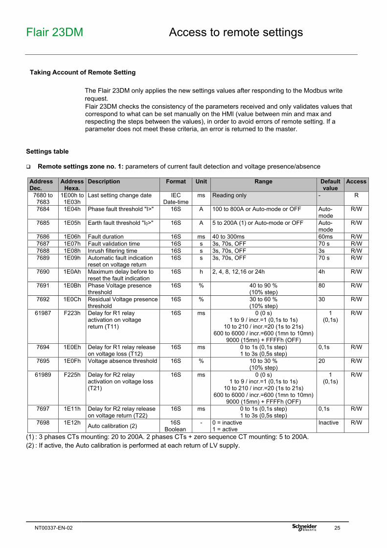
Taking Account of Remote Setting
The Flair 23DM only applies the new settings values after responding to the Modbus write request. Flair 23DM checks the consistency of the parameters received and only validates values that correspond to what can be set manually on the HMI (value between min and max and respecting the steps between the values), in order to avoid errors of remote setting. If a parameter does not meet these criteria, an error is returned to the master.
Settings table
Remote settings zone no. 1: parameters of current fault detection and voltage presence/absence
Address Dec.
Address Hexa.
Description Format Unit Range Default value
Access
7680 to 7683
1E00h to 1E03h
Last setting change date IEC Date-time
ms Reading only - R
7684 1E04h Phase fault threshold "I>" 16S A 100 to 800A or Auto-mode or OFF Auto-mode
R/W
7685 1E05h Earth fault threshold "I0>" 16S A 5 to 200A (1) or Auto-mode or OFF Auto-mode
R/W
7686 1E06h Fault duration 16S ms 40 to 300ms 60ms R/W 7687 1E07h Fault validation time 16S s 3s, 70s, OFF 70 s R/W 7688 1E08h Inrush filtering time 16S s 3s, 70s, OFF 3s R/W 7689 1E09h Automatic fault indication
reset on voltage return 16S s 3s, 70s, OFF 70 s R/W
7690 1E0Ah Maximum delay before to reset the fault indication
16S h 2, 4, 8, 12,16 or 24h 4h R/W
7691 1E0Bh Phase Voltage presence threshold
16S % 40 to 90 % (10% step)
80 R/W
7692 1E0Ch Residual Voltage presence threshold
16S % 30 to 60 % (10% step)
30 R/W
61987 F223h Delay for R1 relay activation on voltage return (T11)
16S ms 0 (0 s) 1 to 9 / incr.=1 (0,1s to 1s)
10 to 210 / incr.=20 (1s to 21s) 600 to 6000 / incr.=600 (1mn to 10mn)
9000 (15mn) + FFFFh (OFF)
1 (0,1s)
R/W
7694 1E0Eh Delay for R1 relay release on voltage loss (T12)
16S ms 0 to 1s (0,1s step) 1 to 3s (0,5s step)
0,1s R/W
7695 1E0Fh Voltage absence threshold 16S % 10 to 30 % (10% step)
20 R/W
61989 F225h Delay for R2 relay activation on voltage loss (T21)
16S ms 0 (0 s) 1 to 9 / incr.=1 (0,1s to 1s)
10 to 210 / incr.=20 (1s to 21s) 600 to 6000 / incr.=600 (1mn to 10mn)
9000 (15mn) + FFFFh (OFF)
1 (0,1s)
R/W
7697 1E11h Delay for R2 relay release on voltage return (T22)
16S ms 0 to 1s (0,1s step) 1 to 3s (0,5s step)
0,1s R/W
7698 1E12h Auto calibration (2) 16S Boolean
- 0 = inactive 1 = active
Inactive R/W
(1) : 3 phases CTs mounting: 20 to 200A. 2 phases CTs + zero sequence CT mounting: 5 to 200A. (2) : If active, the Auto calibration is performed at each return of LV supply.
Flair 23DM Access to remote settings
26 NT00337-EN-02
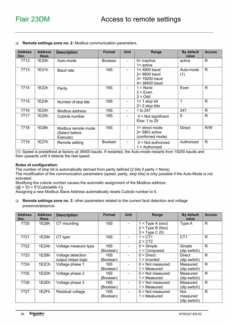
Remote settings zone no. 2: Modbus communication parameters.
Address Dec.
Address Hexa.
Description Format Unit Range By default value
Access
7712 1E20h Auto-mode Boolean - 0= inactive 1= active
(1): Speed is predefined at factory at 38400 bauds. If restarted, the Auto-mode restarts from 19200 bauds and then upwards until it detects the real speed. Rules of configuration: The number of stop bit is automatically derived from parity defined (2 bits if parity = None). The modification of the communication parameters (speed, parity, stop bits) is only possible if the Auto-Mode is not activated. Modifying the cubicle number causes the automatic assignment of the Modbus address: (@ = 33 + 5*(CubicleNb-1)) Assigning a new Modbus Slave Address automatically resets Cubicle number to 0. Remote settings zone no. 3: other parameters related to the current fault detection and voltage
presence/absence.
Address Dec.
Address Hexa.
Description Format Unit Range By default value
Access
7720 1E28h CT mounting 16S - 1 = Type A (ooo) 2 = Type B (0oo) 3 = Type C (0)
Type A R
7721 1E29h CT type 16S - 1 = CT1 2 = CT2
CT1 R
7722 1E2Ah Voltage measure type 16S (Boolean)
- 0 = Simple 1 = Composed
Simple (dip switch)
R
7723 1E2Bh Voltage detection output relays logic
16S (Boolean)
- 0 = Direct 1 = Inverted
Direct (dip switch)
R
7724 1E2Ch Voltage phase 1 16S (Boolean)
- 0 = Not measured 1 = Measured
Measured (dip switch)
R
7725 1E2Dh Voltage phase 2 16S (Boolean)
- 0 = Not measured 1 = Measured
Measured (dip switch)
R
7726 1E2Eh Voltage phase 3 16S (Boolean)
- 0 = Not measured 1 = Measured
Measured (dip switch)
R
7727 1E2Fh Residual voltage 16S (Boolean)
- 0 = Not measured 1 = Measured
Not measured (dip switch)
R
Flair 23DM Date and time setting and synchronization
NT00337-EN-02 27
2.12 Date and Time-Setting and Synchronization Introduction
The Flair 23DM manages the date and time internally. If the auxiliary power supply fails, this information continues to be maintained for a period of 5 minutes in the absence of charging current, or longer if there is a charging current and in case of CT mounting type A or B. The Flair 23DM internal time is used in particular to date alarms and events. The Flair 23DM also delivers a Flair 23DM time incorrect data item (bit 04) to the control word, indicating the need to set the time.
Time and date setting
When the Flair 23DM is energized, the time can be set if the product receives a specific time setting command via the Modbus communication. The clock, once set, only starts when the auto-calibration phase is complete. The time and date are set: by writing, in a single block, the new date and time value in the synchronization zone
(addresses 0002h to 0005h) by using function 43 with sub-function 16.
Synchronization
The time frame is used both for setting the time and synchronizing the Flair 23DM. In this case, it should be transmitted regularly at close intervals (10 to 60 seconds) to obtain a synchronous time. It is usually transmitted by broadcasting (slave number = 0). In synchronous state, the absence of receipt of a time frame for more than 200 seconds causes a loss of synchronism (bit 05 of the control word at 1). On receipt of the date and time, the Flair 23DM saves the new date. It also checks whether the difference between this new date and the current date is more than 100 ms. If so, the Flair 23DM changes to non- synchronous state (bit 05 of the control word at 1). It will return to synchronous state (bit 05 of the control word at 0) as soon as the time difference between the new date it has received and the current date is less than 100 ms
Synchronization cycle
Each synchronization cycle is executed as follows: Phase Description
1 The supervisor writes its date and time value in the synchronization zone or by function 43-16
2 The Flair 23DM changes to non-synchronous state (bit 05 of the control word at 1) and resets its clock.
3 If the reset amplitude is less than 100 ms, the Flair 23DM changes back to synchronous state.
Flair 23DM Date and time setting and synchronization
28 NT00337-EN-02
Events generated
At each power-up, Flair23DM generates successively the following events: “Appearance of the incorrect time” event “Appearance of the Not synchronous” event At the first broadcast of synchronization message by master (with date & time), slave generates successively the following events: “Disappearance of the incorrect time” event “Disappearance of the Not synchronous” event After loss of synchronization, slave generates the following event: “Appearance of the Not synchronous” event After return of synchronization, slave generates the following event: “Disappearance of the Not synchronous” event
Clock accuracy
The clock accuracy is linked to the master and its control of the time frame transmission delay on the communication network. Before sending a time frame, the supervisor must ensure that all the read requests sent have received a response. Synchronization of the Flair 23DM is performed immediately after the frame is received. For optimum synchronization, the supervisor must compensate for the frame transmission time. The frame transmission time is compensated by the Flair 23DM. If the frames pass through a gateway (multi-master operation), make sure that this does not slow down the frames.
Flair 23DM Managing the date and time using function 43
NT00337-EN-02 29
2.13 Managing the Date and Time Using Function 43 Introduction
Access to and setting the date and time on Flair 23DM is also possible via two sub-functions of the Modbus 43 function. These two sub-functions will be referred to as function 43-15 and function 43-16 hereafter.
Function 43-15
Function 43-15 is a read Flair 23DM date and current time function. It is an alternative to reading the Modbus registers at addresses 0002h to 0005h inclusive. The IEC 60870-5-4 format is used for data returned by function 43-15 (common to reading via the Modbus registers). Request frame structure: Slave Number Function MEI Type
43 (decimal) 15 (decimal) 0 Date and time in IEC 60870-5-4 format
CRC 16
Flair 23DM Managing the date and time using function 43
30 NT00337-EN-02
Function 43-16
Function 43-16 is a write Flair 23DM date and current time function. It is an alternative to writing the Modbus registers at addresses 0002h to 0005h inclusive. The IEC 60870-5-4 format is used for data supplied to function 43-16 (common to reading via the Modbus registers). Correct request frame structure: Slave Number Function MEI Type


![Electrical Machines Laboratory - Terco [Swedish] · electrical machines with 60 Hz ratings. MV 1026-225 Electric Torque Meter System As MV 1036-225, but the drive motor has a double](https://static.documents.pub/doc/80x56/5e68f9af6eb6c136d81cb8d6/electrical-machines-laboratory-terco-swedish-electrical-machines-with-60-hz.jpg)
