165
MVI56E-FLN ControlLogix Platform FA Control Network Ethernet Communication Module April 18, 2011 USER MANUAL

MVI56E-FLN ControlLogix Platform
FA Control Network Ethernet Communication Module
April 18, 2011
USER MANUAL

Your Feedback Please
We always want you to feel that you made the right decision to use our products. If you have suggestions, comments, compliments or complaints about our products, documentation, or support, please write or call us.
How to Contact Us
ProSoft Technology 5201 Truxtun Ave., 3rd Floor Bakersfield, CA 93309 +1 (661) 716-5100 +1 (661) 716-5101 (Fax) www.prosoft-technology.com [email protected]
Copyright © 2011 ProSoft Technology, Inc., all rights reserved.
MVI56E-FLN User Manual
April 18, 2011
ProSoft Technology ®, ProLinx
®, inRAx
®, ProTalk
®, and RadioLinx
® are Registered Trademarks of ProSoft
Technology, Inc. All other brand or product names are or may be trademarks of, and are used to identify products and services of, their respective owners.
ProSoft Technology® Product Documentation
In an effort to conserve paper, ProSoft Technology no longer includes printed manuals with our product shipments. User Manuals, Datasheets, Sample Ladder Files, and Configuration Files are provided on the enclosed CD-ROM, and are available at no charge from our web site: www.prosoft-technology.com

Electrical Ratings
� Backplane Current Load: 800 mA @ 5 Vdc; 3 mA @ 24 Vdc� Operating Temperature: 0°C to 60°C (32°F to 140°F)� Storage Temperature: -40°C to 85°C (-40°F to 185°F)� Shock: 30 g operational; 50 g non-operational; Vibration: 5 g from 10 Hz to 150 Hz� Relative Humidity 5% to 95% (without condensation)� All phase conductor sizes must be at least 1.3 mm (squared) and all earth ground conductors must be at least
4mm (squared).
Important Safety Information
North America Warnings
A Warning - Explosion Hazard - Substitution of components may impair suitability for Class I, Division 2. B Warning - Explosion Hazard - When in Hazardous Locations, turn off power before replacing or rewiring
modules. C Warning - Explosion Hazard - Do not disconnect equipment unless power has been switched off or the area is
known to be nonhazardous. D Suitable for use in Class I, Division 2 Groups A, B, C, and D, Hazardous Locations or Non-Hazardous Locations.
ATEX/IECEx Warnings and Conditions of Safe Usage:
Power, Input, and Output (I/O) wiring must be in accordance with the authority having jurisdiction A Warning - Explosion Hazard - When in hazardous locations, turn off power before replacing or wiring modules. B Warning - Explosion Hazard - Do not disconnect equipment unless power has been switched off or the area is
known to be non-hazardous. C These products are intended to be mounted in an ATEX/IECEx Certified, tool-secured, IP54 enclosure. The devices
40%. This device must be used only with ATEX certified backplanes. D Before operating the reset switch, be sure the area is known to be non-hazardous.
shall provide external means to prevent the rated voltage being exceeded by transient disturbances of more than
<Ex> II 3 G Ex nA IIC T4 Gc0°C <= Ta <= 60°C -25°C <= Ta <= 70°C (XT models only) II – Equipment intended for above ground use (not for use in mines). 3 – Category 3 equipment, investigated for normal operation only. G – Equipment protected against explosive gasses. <cULus> E183151 Class I, DIV 2, groups A,B,C,D T5 for all models 0°C to +60°C -25°C to +70°C (XT models only)

Agency Approvals and Certifications
Agency Applicable Standards
RoHS
ATEX EN60079-0 July 2006
EN60079-15 October 2005
CSA IEC61010
CE EMC-EN61326-1:2006
EN61000-6-4:2007
CSA CB Safety CA/10533/CSA IEC 61010-1 Ed. 2
CB 243333-2056722 (2090408)
GOST-R EN61010
JEMA JIS B 3251; JEM 1480, JEM-TR 213; JEM-TR 214
243333 ME06
Battery Life Advisory
Note: Modules manufactured after April 1st, 2011 do not contain a battery. For modules manufactured before that date the following applies:
The module uses a rechargeable Lithium Vanadium Pentoxide battery to back up the real-time clock and CMOS settings. The battery itself should last for the life of the module. However, if left in an unpowered state for 14 to 21 days, the battery may become fully discharged and require recharging by being placed in a powered-up ControlLogix chassis. The time required to fully recharge the battery may be as long as 24 hours.
Once it is fully charged, the battery provides backup power for the CMOS setup and the real-time clock for approximately 21 days. Before you remove a module from its power source, ensure that the battery within the module is fully charged (the BATT LED on the front of the module goes OFF when the battery is fully charged). If the battery is allowed to become fully discharged, the module will revert to the default BIOS and clock settings.
Note: The battery is not user-replaceable or serviceable.

MVI56E-FLN ♦ ControlLogix Platform Contents FA Control Network Ethernet Communication Module User Manual
ProSoft Technology, Inc. Page 5 of 165 April 18, 2011
Contents
Your Feedback Please ........................................................................................................................ 2
How to Contact Us .............................................................................................................................. 2
ProSoft Technology® Product Documentation .................................................................................... 2
Important Safety Information ............................................................................................................... 3
Battery Life Advisory ........................................................................................................................... 4
Guide to the MVI56E-FLN User Manual 9
1 Start Here 11
1.1 What's New? ........................................................................................................... 12
1.2 System Requirements ............................................................................................. 13
1.3 Package Contents ................................................................................................... 14
1.4 Setting Jumpers ...................................................................................................... 15
1.5 Installing the Module in the Rack ............................................................................ 16
1.6 Installing ProSoft Configuration Builder .................................................................. 18
1.7 Connecting Your PC to the Module ......................................................................... 19
1.8 Setting Up a Temporary IP Address ....................................................................... 20
1.9 Connecting to the Module's Web Page ................................................................... 25
1.10 Using the RSLogix 5000 Sample Project ................................................................ 26
1.10.1 Opening the Sample Ladder Logic .......................................................................... 26
1.10.2 Adding the Module to an Existing Project ............................................................... 31
1.10.3 Connecting Your PC to the ControlLogix Processor ............................................... 34
1.10.4 Downloading the Sample Program to the Processor .............................................. 35
2 Configuring the MVI56E-FLN Module 37
2.1 Using ProSoft Configuration Builder Software ........................................................ 37
2.1.1 Setting Module Parameters ..................................................................................... 38
2.2 Module Configuration .............................................................................................. 40
2.2.1 FL-net ...................................................................................................................... 40
2.2.2 Ethernet Configuration ............................................................................................ 44
2.3 Downloading the Project to the Module .................................................................. 46
2.4 Configuring the FL-net Device ................................................................................ 48
2.4.1 Setting Up the FL/ET-T-V2 Module ......................................................................... 48
2.4.2 FL/ET-V2 Configuration with PCwin ........................................................................ 49
2.4.3 Downloading the Project ......................................................................................... 54
2.4.4 Connecting the MVI56E-FLN Module to the FL/ET-T-V2 ....................................... 54
2.5 Verifying Communication ........................................................................................ 55
2.5.1 Using the Diagnostics Menu in ProSoft Configuration Builder ................................ 55
2.5.2 The Diagnostics Menu ............................................................................................. 58
2.5.3 Checking Status through ControlLogix Controller Tags .......................................... 65
2.5.4 Transferring Data .................................................................................................... 74
3 Diagnostics and Troubleshooting 79
3.1 Reading Status Data from the Module .................................................................... 79
3.1.1 Own-Node Status information ................................................................................. 80

Contents MVI56E-FLN ♦ ControlLogix Platform User Manual FA Control Network Ethernet Communication Module
Page 6 of 165 ProSoft Technology, Inc. April 18, 2011
3.2 Diagnostics Menu Items ......................................................................................... 82
3.2.1 Monitoring Module Information ............................................................................... 82
3.2.2 Monitoring Backplane Information .......................................................................... 84
3.3 LED Status Indicators ............................................................................................. 85
3.3.1 Scrolling LED Status Indicators .............................................................................. 85
3.3.2 Ethernet LED Indicators .......................................................................................... 86
3.3.3 Non-Scrolling LED Status Indicators ...................................................................... 87
3.4 Clearing a Fault Condition ...................................................................................... 88
3.5 Troubleshooting ...................................................................................................... 89
4 Reference 91
4.1 Product Specifications ............................................................................................ 91
4.1.1 Features .................................................................................................................. 92
4.1.2 General Specifications ............................................................................................ 93
4.1.3 Hardware Specifications ......................................................................................... 93
4.1.4 Functional Specifications ........................................................................................ 94
4.2 Functional Overview ............................................................................................... 95
4.2.1 About FL-net Protocol ............................................................................................. 95
4.2.2 Data Flow between Module and Processor .......................................................... 103
4.2.3 Backplane Data Transfer ...................................................................................... 104
4.3 Implementation of FL-net ...................................................................................... 110
4.3.1 Information Tables ................................................................................................ 111
4.3.2 Upper Layer Status Read Definition ..................................................................... 114
4.3.3 Lower Layer Protocol ............................................................................................ 119
4.4 FL-net Protocol and Network ................................................................................ 120
4.4.1 Understanding the Basics of FL-net ..................................................................... 120
4.4.2 Data Frame ID of FL-net ....................................................................................... 120
4.4.3 Allowable Refresh Cycle Time .............................................................................. 121
4.4.4 Memory Resources ............................................................................................... 121
4.4.5 Message Transmissions ....................................................................................... 122
4.4.6 Message Transmission Function .......................................................................... 124
4.4.7 Data Volume and Number of Frames ................................................................... 126
4.4.8 Network Management ........................................................................................... 127
4.4.9 Masterless Transmission Management ................................................................ 127
4.4.10 FA Link Protocol.................................................................................................... 130
4.5 Error and Status Data ........................................................................................... 132
4.5.1 Status Data ........................................................................................................... 132
4.6 FL-net Device Profile for MVI56E-FLN Module .................................................... 133
4.6.1 Text Notation of Profile ......................................................................................... 133
4.7 Module Power Up ................................................................................................. 136
4.7.1 Main Logic Loop ................................................................................................... 136
4.8 State Transition Diagram ...................................................................................... 136
4.8.1 A. State Definitions ............................................................................................... 136
4.8.2 B. Initialization Monitoring ..................................................................................... 138
4.8.3 C. Network Initialization ........................................................................................ 140
4.8.4 D. Halfway Joining Initialization ............................................................................ 141
4.8.5 E. Waiting for Token ............................................................................................. 142
4.8.6 F. Token Holding .................................................................................................. 143
4.8.7 G. Message Transmission State Transition .......................................................... 144
4.8.8 H. Message Reception State Transition ............................................................... 145
4.9 Cable Connections - MVI56E-FLN ....................................................................... 146
4.9.1 Ethernet Connection ............................................................................................. 146

MVI56E-FLN ♦ ControlLogix Platform Contents FA Control Network Ethernet Communication Module User Manual
ProSoft Technology, Inc. Page 7 of 165 April 18, 2011
4.9.2 Ethernet Cable Specifications ............................................................................... 146
5 Support, Service & Warranty 149
Contacting Technical Support ......................................................................................................... 149
5.1 Return Material Authorization (RMA) Policies and Conditions.............................. 151
5.1.1 Returning Any Product .......................................................................................... 151
5.1.2 Returning Units Under Warranty ........................................................................... 152
5.1.3 Returning Units Out of Warranty ........................................................................... 152
5.2 LIMITED WARRANTY ........................................................................................... 153
5.2.1 What Is Covered By This Warranty ....................................................................... 153
5.2.2 What Is Not Covered By This Warranty ................................................................ 154
5.2.3 Disclaimer Regarding High Risk Activities ............................................................ 154
5.2.4 Intellectual Property Indemnity .............................................................................. 155
5.2.5 Disclaimer of all Other Warranties ........................................................................ 155
5.2.6 Limitation of Remedies ** ...................................................................................... 156
5.2.7 Time Limit for Bringing Suit ................................................................................... 156
5.2.8 No Other Warranties ............................................................................................. 156
5.2.9 Allocation of Risks ................................................................................................. 156
5.2.10 Controlling Law and Severability ........................................................................... 157
Glossary of Terms 159
Index 163

Contents MVI56E-FLN ♦ ControlLogix Platform User Manual FA Control Network Ethernet Communication Module
Page 8 of 165 ProSoft Technology, Inc. April 18, 2011

MVI56E-FLN ♦ ControlLogix Platform Guide to the MVI56E-FLN User Manual FA Control Network Ethernet Communication Module User Manual
ProSoft Technology, Inc. Page 9 of 165 April 18, 2011
Guide to the MVI56E-FLN User Manual
Function Section to Read Details
Introduction
(Must Do)
→ Start Here (page 11) This section introduces the customer to the module. Included are: package contents, system requirements, hardware installation, and basic configuration.
Diagnostic and Troubleshooting
→ Diagnostics and Troubleshooting (page 79)
This section describes Diagnostic and Troubleshooting procedures.
Reference
Product Specifications
Functional Overview
→ Reference (page 91)
Product Specifications (page 91)
Functional Overview (page 95)
These sections contain general references associated with this product, Specifications, and the Functional Overview.
Support, Service, and Warranty
Index
→ Support, Service and Warranty (page 149)
Index
This section contains Support, Service and Warranty information.
Index of chapters.

Guide to the MVI56E-FLN User Manual MVI56E-FLN ♦ ControlLogix Platform User Manual FA Control Network Ethernet Communication Module
Page 10 of 165 ProSoft Technology, Inc. April 18, 2011
MVI56E-FLN ♦ ControlLogix Platform Start Here FA Control Network Ethernet Communication Module User Manual
ProSoft Technology, Inc. Page 11 of 165 April 18, 2011
1 Start Here
In This Chapter
� What's New? ......................................................................................... 12
� System Requirements ........................................................................... 13
� Package Contents ................................................................................. 14
� Setting Jumpers .................................................................................... 15
� Installing the Module in the Rack ........................................................... 16
� Installing ProSoft Configuration Builder ................................................. 18
� Connecting Your PC to the Module ....................................................... 19
� Setting Up a Temporary IP Address ...................................................... 20
� Connecting to the Module's Web Page ................................................. 25
� Using the RSLogix 5000 Sample Project............................................... 26
To get the most benefit from this User Manual, you should have the following skills:
� Rockwell Automation® RSLogix™ software: launch the program, configure ladder logic, and transfer the ladder logic to the processor
� Microsoft Windows: install and launch programs, execute menu commands, navigate dialog boxes, and enter data
� Hardware installation and wiring: install the module, and safely connect FL-net and ControlLogix devices to a power source and to the MVI56E-FLN module’s application port(s)
Start Here MVI56E-FLN ♦ ControlLogix Platform User Manual FA Control Network Ethernet Communication Module
Page 12 of 165 ProSoft Technology, Inc. April 18, 2011
1.1 What's New?
MVI56E products are backward compatible with existing MVI56 products, ladder logic, and module configuration files already in use. Easily swap and upgrade products while benefiting from an array of new features designed to improve interoperability and enhance ease of use.
� ProSoft Configuration Builder (PCB): New Windows software for diagnostics, connecting via the module's Ethernet port to upload/download module configuration information and access troubleshooting features and functions.
� ProSoft Discovery Service (PDS): Utility software to find and display a list of MVI56E modules on the network and to temporarily change an IP address to connect with a module's web page.
� Personality Card: An industrial compact flash memory card storing the module’s complete configuration and Ethernet settings, allowing quick and easy replacement.
� LED Scrolling Diagnostic Display: 4-character, alphanumeric display, providing English messages for status and alarm data, and for processor and network communication status.

MVI56E-FLN ♦ ControlLogix Platform Start Here FA Control Network Ethernet Communication Module User Manual
ProSoft Technology, Inc. Page 13 of 165 April 18, 2011
1.2 System Requirements
The MVI56E-FLN module requires the following minimum hardware and software components:
� Rockwell Automation ControlLogix® processor (firmware version 10 or higher), with compatible power supply, and one free slot in the rack for the MVI56E-FLN module. The module requires 800 mA of available 5 Vdc power
� Rockwell Automation RSLogix 5000 programming software � Rockwell Automation RSLinx® communication software version 2.51 or higher � ProSoft Configuration Builder (PCB) (included) � ProSoft Discovery Service (PDS) (included in PCB) � Pentium® II 450 MHz minimum. Pentium III 733 MHz (or better)
recommended � Supported operating systems:
o Microsoft Windows® Vista o Microsoft Windows XP Professional with Service Pack 1 or 2 o Microsoft Windows 2000 Professional with Service Pack 1, 2, or 3 o Microsoft Windows Server 2003
� 128 Mbytes of RAM minimum, 256 Mbytes of RAM recommended � 100 Mbytes of free hard disk space (or more based on application
requirements) � 256-color VGA graphics adapter, 800 x 600 minimum resolution (True Color
1024 × 768 recommended) � CD-ROM drive
Note: The Hardware and Operating System requirements in this list are the minimum recommended to install and run software provided by ProSoft Technology®. Other third party applications may have different minimum requirements. Refer to the documentation for any third party applications for system requirements. Note: You can install the module in a local or remote rack. For remote rack installation, the module requires EtherNet/IP or ControlNet communication with the processor.
Start Here MVI56E-FLN ♦ ControlLogix Platform User Manual FA Control Network Ethernet Communication Module
Page 14 of 165 ProSoft Technology, Inc. April 18, 2011
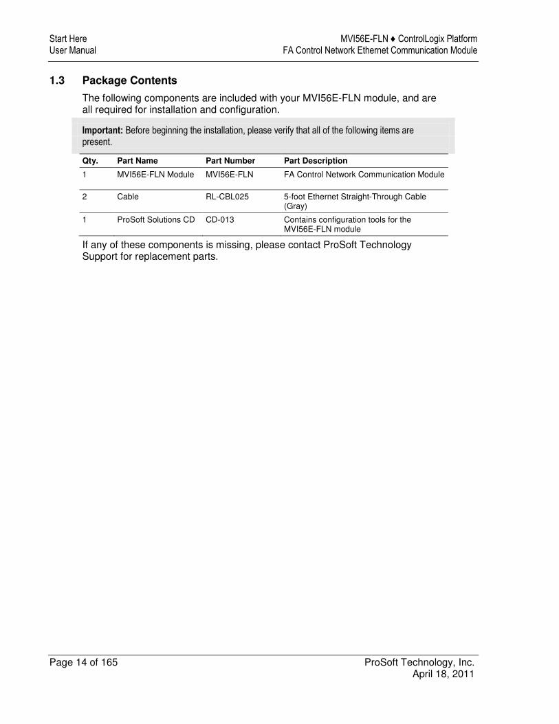
1.3 Package Contents
The following components are included with your MVI56E-FLN module, and are all required for installation and configuration.
Important: Before beginning the installation, please verify that all of the following items are present.
Qty. Part Name Part Number Part Description
1 MVI56E-FLN Module MVI56E-FLN FA Control Network Communication Module
2 Cable RL-CBL025 5-foot Ethernet Straight-Through Cable (Gray)
1 ProSoft Solutions CD CD-013 Contains configuration tools for the MVI56E-FLN module
If any of these components is missing, please contact ProSoft Technology Support for replacement parts.

MVI56E-FLN ♦ ControlLogix Platform Start Here FA Control Network Ethernet Communication Module User Manual
ProSoft Technology, Inc. Page 15 of 165 April 18, 2011
1.4 Setting Jumpers
The Setup Jumper acts as "write protection" for the module’s flash memory. In "write protected" mode, the Setup pins are not connected, and the module’s firmware cannot be overwritten. Do not jumper the Setup pins together unless you are directed to do so by ProSoft Technical Support.
The following illustration shows the MVI56E-FLN jumper configuration.
Note: If you are installing the module in a remote rack, you may prefer to leave the Setup pins jumpered. That way, you can update the module’s firmware without requiring physical access to the module.

Start Here MVI56E-FLN ♦ ControlLogix Platform User Manual FA Control Network Ethernet Communication Module
Page 16 of 165 ProSoft Technology, Inc. April 18, 2011
1.5 Installing the Module in the Rack
If you have not already installed and configured your ControlLogix processor and power supply, please do so before installing the MVI56E-FLN module. Refer to your Rockwell Automation product documentation for installation instructions.
Warning: You must follow all safety instructions when installing this or any other electronic devices. Failure to follow safety procedures could result in damage to hardware or data, or even serious injury or death to personnel. Refer to the documentation for each device you plan to connect to verify that suitable safety procedures are in place before installing or servicing the device.
After you have checked the placement of the jumpers, insert the MVI56E-FLN into the ControlLogix chassis. Use the same technique recommended by Rockwell Automation to remove and install ControlLogix modules.
You can install or remove ControlLogix system components while chassis power is applied and the system is operating. However, please note the following warning.
Warning: When you insert or remove the module while backplane power is on, an electrical arc can occur. An electrical arc can cause personal injury or property damage by sending an erroneous signal to your system’s actuators. This can cause unintended machine motion or loss of process control. Electrical arcs may also cause an explosion when they happen in a hazardous environment. Verify that power is removed or the area is non-hazardous before proceeding. Repeated electrical arcing causes excessive wear to contacts on both the module and its mating connector. Worn contacts may create electrical resistance that can affect module operation.
MVI56E-FLN ♦ ControlLogix Platform Start Here FA Control Network Ethernet Communication Module User Manual
ProSoft Technology, Inc. Page 17 of 165 April 18, 2011
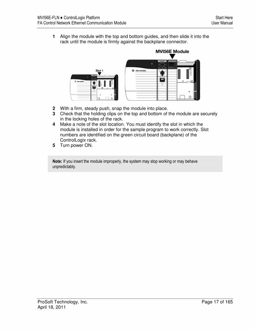
1 Align the module with the top and bottom guides, and then slide it into the rack until the module is firmly against the backplane connector.
2 With a firm, steady push, snap the module into place. 3 Check that the holding clips on the top and bottom of the module are securely
in the locking holes of the rack. 4 Make a note of the slot location. You must identify the slot in which the
module is installed in order for the sample program to work correctly. Slot numbers are identified on the green circuit board (backplane) of the ControlLogix rack.
5 Turn power ON.
Note: If you insert the module improperly, the system may stop working or may behave unpredictably.
Start Here MVI56E-FLN ♦ ControlLogix Platform User Manual FA Control Network Ethernet Communication Module
Page 18 of 165 ProSoft Technology, Inc. April 18, 2011
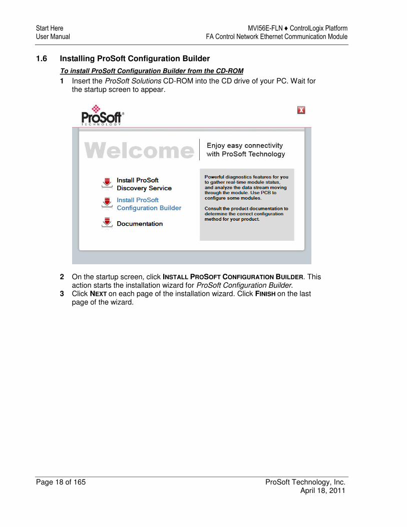
1.6 Installing ProSoft Configuration Builder
To install ProSoft Configuration Builder from the CD-ROM
1 Insert the ProSoft Solutions CD-ROM into the CD drive of your PC. Wait for the startup screen to appear.
2 On the startup screen, click INSTALL PROSOFT CONFIGURATION BUILDER. This action starts the installation wizard for ProSoft Configuration Builder.
3 Click NEXT on each page of the installation wizard. Click FINISH on the last page of the wizard.
MVI56E-FLN ♦ ControlLogix Platform Start Here FA Control Network Ethernet Communication Module User Manual
ProSoft Technology, Inc. Page 19 of 165 April 18, 2011
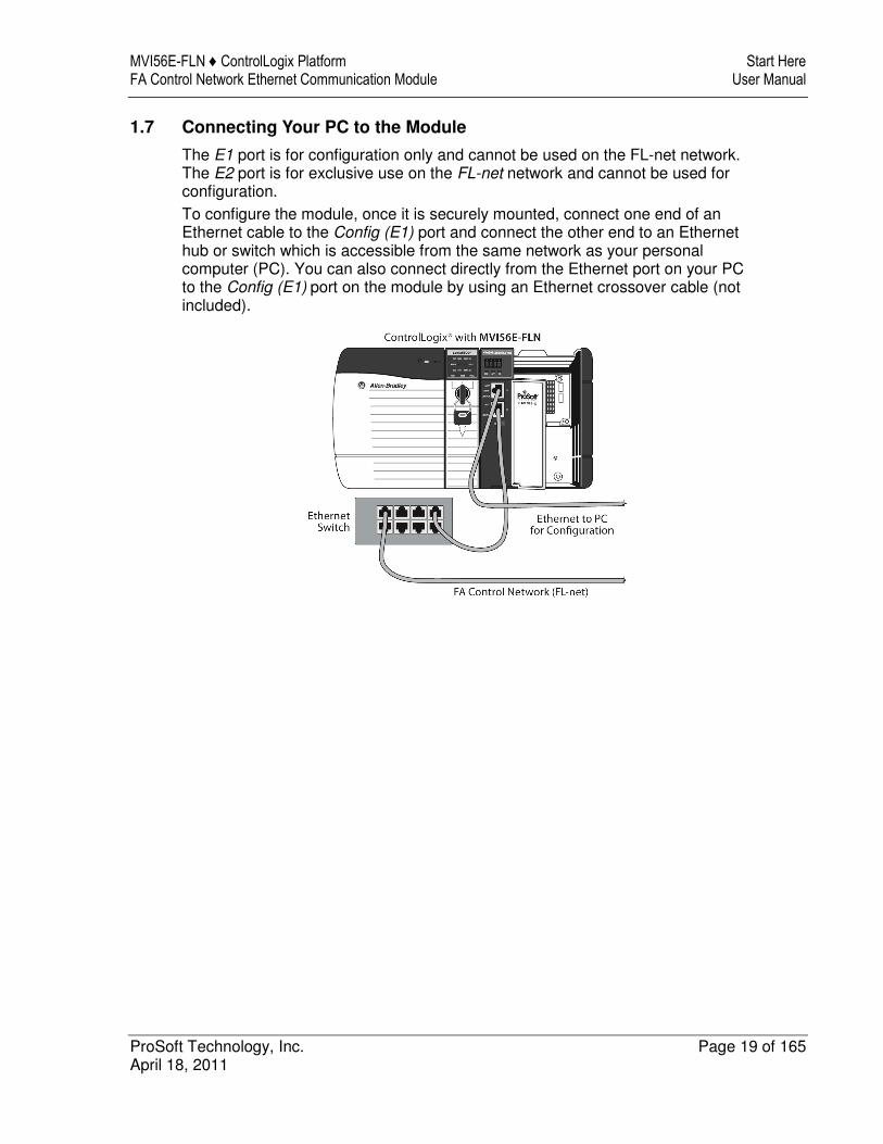
1.7 Connecting Your PC to the Module
The E1 port is for configuration only and cannot be used on the FL-net network. The E2 port is for exclusive use on the FL-net network and cannot be used for configuration.
To configure the module, once it is securely mounted, connect one end of an Ethernet cable to the Config (E1) port and connect the other end to an Ethernet hub or switch which is accessible from the same network as your personal computer (PC). You can also connect directly from the Ethernet port on your PC to the Config (E1) port on the module by using an Ethernet crossover cable (not included).

Start Here MVI56E-FLN ♦ ControlLogix Platform User Manual FA Control Network Ethernet Communication Module
Page 20 of 165 ProSoft Technology, Inc. April 18, 2011
1.8 Setting Up a Temporary IP Address
Important: ProSoft Configuration Builder locates MVI56E-FLN modules through UDP broadcast messages. These messages may be blocked by routers or layer 3 switches. In that case, ProSoft Discovery Service will be unable to locate the modules. To use ProSoft Configuration Builder, arrange the Ethernet connection so that there is no router/layer 3 switch between the computer and the module OR reconfigure the router/layer 3 switch to allow the routing of the UDP broadcast messages.
1 Click the START button, and then navigate to PROGRAMS / PROSOFT
TECHNOLOGY.
2 Click to start ProSoft Configuration Builder.
MVI56E-FLN ♦ ControlLogix Platform Start Here FA Control Network Ethernet Communication Module User Manual
ProSoft Technology, Inc. Page 21 of 165 April 18, 2011
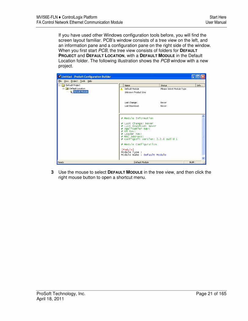
If you have used other Windows configuration tools before, you will find the screen layout familiar. PCB’s window consists of a tree view on the left, and an information pane and a configuration pane on the right side of the window. When you first start PCB, the tree view consists of folders for DEFAULT
PROJECT and DEFAULT LOCATION, with a DEFAULT MODULE in the Default Location folder. The following illustration shows the PCB window with a new project.
3 Use the mouse to select DEFAULT MODULE in the tree view, and then click the right mouse button to open a shortcut menu.
Start Here MVI56E-FLN ♦ ControlLogix Platform User Manual FA Control Network Ethernet Communication Module
Page 22 of 165 ProSoft Technology, Inc. April 18, 2011
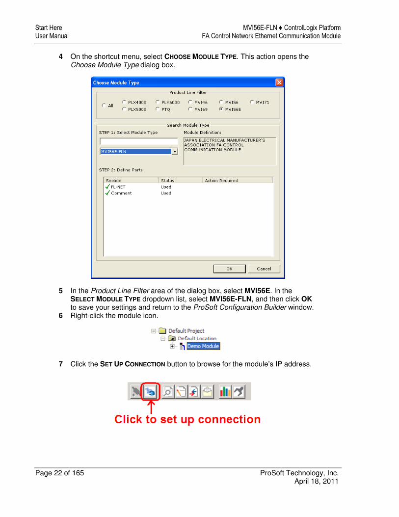
4 On the shortcut menu, select CHOOSE MODULE TYPE. This action opens the Choose Module Type dialog box.
5 In the Product Line Filter area of the dialog box, select MVI56E. In the SELECT MODULE TYPE dropdown list, select MVI56E-FLN, and then click OK
to save your settings and return to the ProSoft Configuration Builder window. 6 Right-click the module icon.
7 Click the SET UP CONNECTION button to browse for the module’s IP address.
MVI56E-FLN ♦ ControlLogix Platform Start Here FA Control Network Ethernet Communication Module User Manual
ProSoft Technology, Inc. Page 23 of 165 April 18, 2011
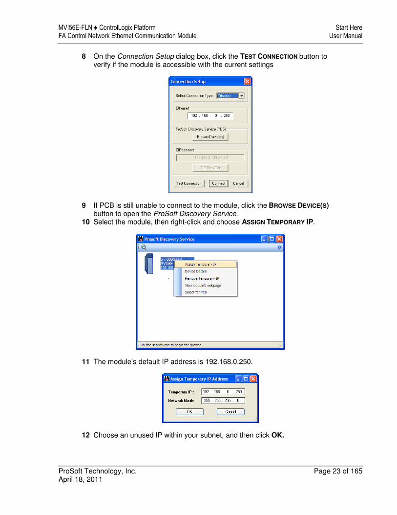
8 On the Connection Setup dialog box, click the TEST CONNECTION button to verify if the module is accessible with the current settings
9 If PCB is still unable to connect to the module, click the BROWSE DEVICE(S) button to open the ProSoft Discovery Service.
10 Select the module, then right-click and choose ASSIGN TEMPORARY IP.
11 The module’s default IP address is 192.168.0.250.
12 Choose an unused IP within your subnet, and then click OK.
Start Here MVI56E-FLN ♦ ControlLogix Platform User Manual FA Control Network Ethernet Communication Module
Page 24 of 165 ProSoft Technology, Inc. April 18, 2011
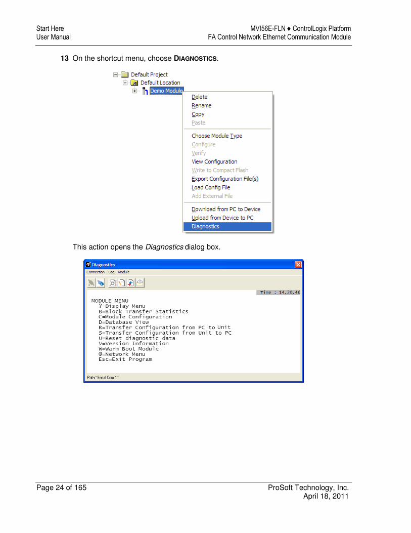
13 On the shortcut menu, choose DIAGNOSTICS.
This action opens the Diagnostics dialog box.

MVI56E-FLN ♦ ControlLogix Platform Start Here FA Control Network Ethernet Communication Module User Manual
ProSoft Technology, Inc. Page 25 of 165 April 18, 2011
1.9 Connecting to the Module's Web Page
1 In ProSoft Discovery Service, select the MVI56E-FLN module, and then click the right mouse button to open a shortcut menu.
2 On the shortcut menu, choose VIEW MODULE’S WEBPAGE.
The Web page contains general product information, firmware download link, and links to ProSoft Technology's Web site.
Important: The temporary IP address is only valid until the next time the module is initialized. Please refer to Setting Up a Temporary IP Address (page 20) in the MVI56E-FLN User Manual for information on how to set the module’s permanent IP address.

Start Here MVI56E-FLN ♦ ControlLogix Platform User Manual FA Control Network Ethernet Communication Module
Page 26 of 165 ProSoft Technology, Inc. April 18, 2011
1.10 Using the RSLogix 5000 Sample Project
1.10.1 Opening the Sample Ladder Logic
The sample program for your MVI56E-FLN module includes custom tags, data types and ladder logic for data I/O and status monitoring. For most applications, you can run the sample ladder program without modification, or, for advanced applications, you can incorporate the sample program into your existing application.
The inRAx Solutions CD provides one or more versions of the sample ladder logic. The version number appended to the file name corresponds with the firmware version number of your ControlLogix processor. The firmware version and sample program version must match.
Determining the Firmware Version of Your Processor
Important: The RSLinx service must be installed and running on your computer in order for RSLogix to communicate with the processor. Refer to your RSLinx and RSLogix documentation for help configuring and troubleshooting these applications.
1 Connect an RS-232 serial cable from the COM (serial) port on your PC to the communication port on the front of the processor.
2 Start RSLogix 5000 and close any existing project that may be loaded. 3 Open the COMMUNICATIONS menu and choose GO ONLINE. RSLogix will
establish communication with the processor. This may take a few moments. 4 When RSLogix has established communication with the processor, the
Connected To Go Online dialog box will open.

MVI56E-FLN ♦ ControlLogix Platform Start Here FA Control Network Ethernet Communication Module User Manual
ProSoft Technology, Inc. Page 27 of 165 April 18, 2011
5 On the Connected To Go Online dialog box, click the GENERAL tab. This tab shows information about the processor, including the Revision (firmware) version. In the following illustration, the firmware version is 17.2.
Start Here MVI56E-FLN ♦ ControlLogix Platform User Manual FA Control Network Ethernet Communication Module
Page 28 of 165 ProSoft Technology, Inc. April 18, 2011
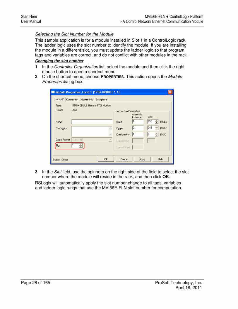
Selecting the Slot Number for the Module
This sample application is for a module installed in Slot 1 in a ControlLogix rack. The ladder logic uses the slot number to identify the module. If you are installing the module in a different slot, you must update the ladder logic so that program tags and variables are correct, and do not conflict with other modules in the rack.
Changing the slot number
1 In the Controller Organization list, select the module and then click the right mouse button to open a shortcut menu.
2 On the shortcut menu, choose PROPERTIES. This action opens the Module Properties dialog box.
3 In the Slot field, use the spinners on the right side of the field to select the slot number where the module will reside in the rack, and then click OK.
RSLogix will automatically apply the slot number change to all tags, variables and ladder logic rungs that use the MVI56E-FLN slot number for computation.

MVI56E-FLN ♦ ControlLogix Platform Start Here FA Control Network Ethernet Communication Module User Manual
ProSoft Technology, Inc. Page 29 of 165 April 18, 2011
Configuring the RSLinx Driver for the PC COM Port
If RSLogix is unable to establish communication with the processor, follow these steps.
1 Open RSLinx. 2 Open the COMMUNICATIONS menu, and choose CONFIGURE DRIVERS.
This action opens the Configure Drivers dialog box.
Note: If the list of configured drivers is blank, you must first choose and configure a driver from the Available Driver Types list. The recommended driver type to choose for serial communication with the processor is RS-232 DF1 Devices.

Start Here MVI56E-FLN ♦ ControlLogix Platform User Manual FA Control Network Ethernet Communication Module
Page 30 of 165 ProSoft Technology, Inc. April 18, 2011
3 Click to select the driver, and then click CONFIGURE. This action opens the Configure RS-232 DF1 Devices dialog box.
4 Click the AUTO-CONFIGURE button. RSLinx will attempt to configure your serial port to work with the selected driver.
5 When you see the message Auto Configuration Successful, click the OK
button to dismiss the dialog box.
Note: If the auto-configuration procedure fails, verify that the cables are connected correctly between the processor and the serial port on your computer, and then try again. If you are still unable to auto-configure the port, refer to your RSLinx documentation for further troubleshooting steps.

MVI56E-FLN ♦ ControlLogix Platform Start Here FA Control Network Ethernet Communication Module User Manual
ProSoft Technology, Inc. Page 31 of 165 April 18, 2011
1.10.2 Adding the Module to an Existing Project
1 Select the I/O Configuration folder in the Controller Organization window of RSLogix 5000, and then click the right mouse button to open a shortcut menu. On the shortcut menu, choose NEW MODULE.
This action opens the Select Module dialog box:
2 Select the 1756-MODULE (GENERIC 1756 MODULE) from the list and click OK. This action opens the New Module dialog box.
Start Here MVI56E-FLN ♦ ControlLogix Platform User Manual FA Control Network Ethernet Communication Module
Page 32 of 165 ProSoft Technology, Inc. April 18, 2011
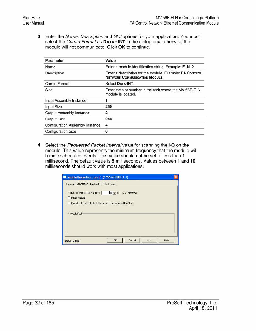
3 Enter the Name, Description and Slot options for your application. You must select the Comm Format as DATA - INT in the dialog box, otherwise the module will not communicate. Click OK to continue.
Parameter Value
Name Enter a module identification string. Example: FLN_2
Description Enter a description for the module. Example: FA CONTROL
NETWORK COMMUNICATION MODULE
Comm Format Select DATA-INT.
Slot Enter the slot number in the rack where the MVI56E-FLN module is located.
Input Assembly Instance 1
Input Size 250
Output Assembly Instance 2
Output Size 248
Configuration Assembly Instance 4
Configuration Size 0
4 Select the Requested Packet Interval value for scanning the I/O on the module. This value represents the minimum frequency that the module will handle scheduled events. This value should not be set to less than 1 millisecond. The default value is 5 milliseconds. Values between 1 and 10 milliseconds should work with most applications.

MVI56E-FLN ♦ ControlLogix Platform Start Here FA Control Network Ethernet Communication Module User Manual
ProSoft Technology, Inc. Page 33 of 165 April 18, 2011
5 Save the module. Click OK to dismiss the dialog box. The Controller Organization window now displays the module's presence.
6 Copy the User-Defined Data Types from the sample program into your existing RSLogix 5000 project.
7 Copy the Controller Tags from the sample program into your project. 8 Copy the Ladder Rungs from the sample program into your project.

Start Here MVI56E-FLN ♦ ControlLogix Platform User Manual FA Control Network Ethernet Communication Module
Page 34 of 165 ProSoft Technology, Inc. April 18, 2011
1.10.3 Connecting Your PC to the ControlLogix Processor
There are several ways to establish communication between your PC and the ControlLogix processor. The following steps show how to establish communication through the serial interface. It is not mandatory that you use the processor's serial interface. You may access the processor through whatever network interface is available on your system. Refer to your Rockwell Automation documentation for information on other connection methods.
1 Connect the right-angle connector end of the cable to your controller at the communications port.
2 Connect the straight connector end of the cable to the serial port on your computer.
MVI56E-FLN ♦ ControlLogix Platform Start Here FA Control Network Ethernet Communication Module User Manual
ProSoft Technology, Inc. Page 35 of 165 April 18, 2011
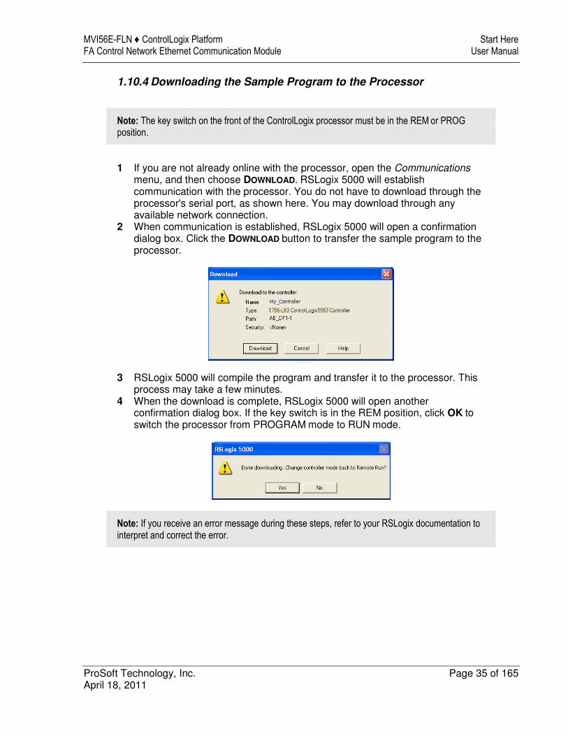
1.10.4 Downloading the Sample Program to the Processor
Note: The key switch on the front of the ControlLogix processor must be in the REM or PROG
position.
1 If you are not already online with the processor, open the Communications
menu, and then choose DOWNLOAD. RSLogix 5000 will establish communication with the processor. You do not have to download through the processor's serial port, as shown here. You may download through any available network connection.
2 When communication is established, RSLogix 5000 will open a confirmation dialog box. Click the DOWNLOAD button to transfer the sample program to the processor.
3 RSLogix 5000 will compile the program and transfer it to the processor. This process may take a few minutes.
4 When the download is complete, RSLogix 5000 will open another confirmation dialog box. If the key switch is in the REM position, click OK to switch the processor from PROGRAM mode to RUN mode.
Note: If you receive an error message during these steps, refer to your RSLogix documentation to interpret and correct the error.

Start Here MVI56E-FLN ♦ ControlLogix Platform User Manual FA Control Network Ethernet Communication Module
Page 36 of 165 ProSoft Technology, Inc. April 18, 2011

MVI56E-FLN ♦ ControlLogix Platform Configuring the MVI56E-FLN Module FA Control Network Ethernet Communication Module User Manual
ProSoft Technology, Inc. Page 37 of 165 April 18, 2011
2 Configuring the MVI56E-FLN Module
In This Chapter
� Using ProSoft Configuration Builder Software ....................................... 37
� Module Configuration ............................................................................ 40
� Downloading the Project to the Module ................................................. 46
� Configuring the FL-net Device ............................................................... 48
� Verifying Communication....................................................................... 55
The purpose of this section of the User Manual is to show the MVI56E-FLN functionality through a typical real-world application. For this example application, the MVI56E-FLN is shown communicating with a Toyoda FL/ET-T-V2 communication module that transfers the data to a TOYODA PC3JG-P processor located on the same rack.
For this example, the MVI56E-FLN node address is 40, and the FL/ET-T-V2 module node address is 10.
2.1 Using ProSoft Configuration Builder Software
ProSoft Configuration Builder (PCB) provides a quick and easy way to manage module configuration files customized to meet your application needs. PCB is not only a powerful solution for new configuration files, but also allows you to import information from previously installed (known working) configurations to new projects.
Note: During startup and initialization, the MVI56E-FLN module receives its protocol and backplane configuration information from the installed Personality Module (Compact Flash). Use ProSoft Configuration Builder to configure module settings and to download changes to the Personality Module.

Configuring the MVI56E-FLN Module MVI56E-FLN ♦ ControlLogix Platform User Manual FA Control Network Ethernet Communication Module
Page 38 of 165 ProSoft Technology, Inc. April 18, 2011
2.1.1 Setting Module Parameters
Notice that the contents of the information pane and the configuration pane changed when you added the MVI56E-FLN module to the project.
At this time, you may wish to rename the Default Project and Default Location folders in the tree view.
Renaming an Object
1 Select the object, and then click the right mouse button to open a shortcut menu. From the shortcut menu, choose RENAME.
2 Type the name to assign to the object. 3 Click away from the object to save the new name.
Configuring Module Parameters
1 Click on the [+] sign next to the module icon to expand module information.
2 Click on the [+] sign next to any icon to view module information and configuration options.
3 Double-click any icon to open an Edit dialog box. 4 To edit a parameter, select the parameter in the left pane and make your
changes in the right pane. 5 Click OK to save your changes.
MVI56E-FLN ♦ ControlLogix Platform Configuring the MVI56E-FLN Module FA Control Network Ethernet Communication Module User Manual
ProSoft Technology, Inc. Page 39 of 165 April 18, 2011
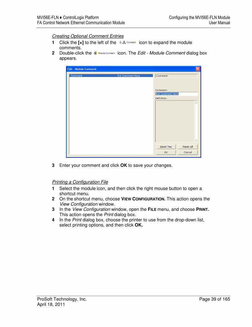
Creating Optional Comment Entries
1 Click the [+] to the left of the icon to expand the module comments.
2 Double-click the icon. The Edit - Module Comment dialog box appears.
3 Enter your comment and click OK to save your changes.
Printing a Configuration File
1 Select the module icon, and then click the right mouse button to open a shortcut menu.
2 On the shortcut menu, choose VIEW CONFIGURATION. This action opens the View Configuration window.
3 In the View Configuration window, open the FILE menu, and choose PRINT. This action opens the Print dialog box.
4 In the Print dialog box, choose the printer to use from the drop-down list, select printing options, and then click OK.

Configuring the MVI56E-FLN Module MVI56E-FLN ♦ ControlLogix Platform User Manual FA Control Network Ethernet Communication Module
Page 40 of 165 ProSoft Technology, Inc. April 18, 2011
2.2 Module Configuration
2.2.1 FL-net
Configure the module to properly transfer data between the ControlLogix processor and the remote FL-net node (Toyoda PLC - TPLC).
Node Name
Up to 10 ASCII characters
This is a user-defined node identification.
It can be set from the upper layer or by a network parameter write message.
When it is set from the network by using message transmission, the node does not secede from the network if only the node name is changed, continuing communication.

MVI56E-FLN ♦ ControlLogix Platform Configuring the MVI56E-FLN Module FA Control Network Ethernet Communication Module User Manual
ProSoft Technology, Inc. Page 41 of 165 April 18, 2011
Area Parameters
The ranges of the top addresses (starting adresses) and sizes of Common Memory Areas 1 and 2 are as follows.
Parameter Range (Words)
Top Address Area Size
Area 1 0 to 511 0 to 512
Area 2 0 to 8191 0 to 8192
These parameters can be set from the upper layer or by a network parameter write message.
When nodes receive a network parameter write message for setting these parameters, the node secedes from the network and rejoins the network in the halfway participation status.
Unless they are set from the upper layer, the node is regarded as having no transmitting area. At this time, however, a token is exchanged.
Configuring Area 1 and Area 2
Each area is defined by its starting address (top address) and word length (size). The following illustration shows the starting addresses and word lengths used in the sample application:

Configuring the MVI56E-FLN Module MVI56E-FLN ♦ ControlLogix Platform User Manual FA Control Network Ethernet Communication Module
Page 42 of 165 ProSoft Technology, Inc. April 18, 2011
Use the following settings to configure the data to transfer from the module to the remote node. This data is transferred from the ControlLogix processor to the MVI56E-FLN module through the FLNETDATA.Output.Area1 and FLNETDATA.Output.Area2 controller tag arrays.
Area 1 Top : 0
Area 1 Size : 50
Area 2 Top : 0
Area 2 Size : 100
Use the following settings to configure the data to transfer from the Common Memory to the processor. This data is transferred from the MVI56E-FLN module to the ControlLogix processor through the FLNETDATA.Input.Area1 and FLNETDATA.Input.Area2 controller tag arrays.
BP Area 1 Top : 50
BP Area 1 Size : 50
BP Area 2 Top : 100
BP Area 2 Size : 100
The next illustration shows how the data is transferred through the module between Common Memory and the ControlLogix processor controller tags arrays:
You can increase the area copied to the processor to also include the produced output data. The following example BP Area settings show how the data copied to the processor can also include the data produced by the module, which is available in the FL-net Common Memory.
BP Area 1 Top : 0
BP Area 1 Size : 100
BP Area 2 Top : 0
BP Area 2 Size : 200
MVI56E-FLN ♦ ControlLogix Platform Configuring the MVI56E-FLN Module FA Control Network Ethernet Communication Module User Manual
ProSoft Technology, Inc. Page 43 of 165 April 18, 2011
This data is transferred from the MVI56E-FLN module to the ControlLogix processor through the FLNETDATA.Input.Area1 and FLNETDATA.Input.Area2 controller tag arrays.
The data read from the remote FL-net starts at FLNETDATA.Input.Area1[50] (50 words) and FLNETDATA.Input.Area2[100] (50 words) in the controller tag arrays. The data produced by the module and available at the FLNET common memory starts at FLNETDATA.Input.Area1[0] (50 words) and FLNETDATA.Input.Area2[0] (50 words) controller tag arrays.
Token Watchdog Time
1 to 255 milliseconds
The Token Watchdog Time (also known as Token Monitoring Time) value is unique for each node and is set from the FA link protocol upper layer as the initial value. If this value is not set, the node is inoperable.
The Token Watchdog Time is notified to all nodes as information on the frame header. Each node uses the value on the frame from each node as a value of the monitoring time until the token-holding node releases the token.
Minimum Frame Interval Time
0 to 50 (in units of 100 milliseconds)
This interval value is a unique for each node and is set from the FA link protocol upper layer as the initial value. If this value is not set, the node is inoperable.
The allowable minimum frame interval means
� The time interval between reception of a token by a node and andtransmission of any frame from the node
or
� The time interval between frames transmitted (from the end of the previousframe until the beginning of the next frame) The allowable minimum frameinterval of each node is notified to all nodes as information on the frameheader. Each node obtains the maximum value from it and recognizes it asthe allowable minimum frame interval to use.
Important Note: For this module to operate correctly on an FL-net network, the Minimum Frame Interval Time must be set to a value of 20 or more for all nodes on the network. If nodes on the network have values less than 20 for this parameter, the module may not be able to join the network.

Configuring the MVI56E-FLN Module MVI56E-FLN ♦ ControlLogix Platform User Manual FA Control Network Ethernet Communication Module
Page 44 of 165 ProSoft Technology, Inc. April 18, 2011
2.2.2 Ethernet Configuration
Use this procedure to modify the temporary Ethernet settings you set for your module in the section on Setting Up a Temporary IP Address (page 20). Here you assign two sets of IP address, subnet mask, and gateway address values, one for each of the two Ethernet ports on the module. The IP address for module's E1 port, which is used exclusively for configuring the module, is entered in the my_ip parameter set. The IP address for the module's E2 port, which is used exclusively for the FL-net network data transfer application, is entered in the my_ip1 parameter set.
1 Determine the network settings for the two ports on your module, with the help of your network administrator if necessary. You will need the following information:
For the configuration port E1:
o my_ip - IP address (fixed IP req.) _____ . _____ . _____ . _____
o netmask - Subnet mask _____ . _____ . _____ . _____
o gateway - Gateway address _____ . _____ . _____ . _____
For the FL-net application port E2:
o my_ip1 - IP address (fixed IP req.) _192_ . _168_ . _250_ . _XXX_
o netmask - Subnet mask _____ . _____ . _____ . _____
o gateway - Gateway address _____ . _____ . _____ . _____
Note: The gateway address is optional, and is not required for networks that do not use a default gateway. The last octet of the my_ip1 address (XXX, above) will be the module's FL-net node address on the FA Control network.
MVI56E-FLN ♦ ControlLogix Platform Configuring the MVI56E-FLN Module FA Control Network Ethernet Communication Module User Manual
ProSoft Technology, Inc. Page 45 of 165 April 18, 2011
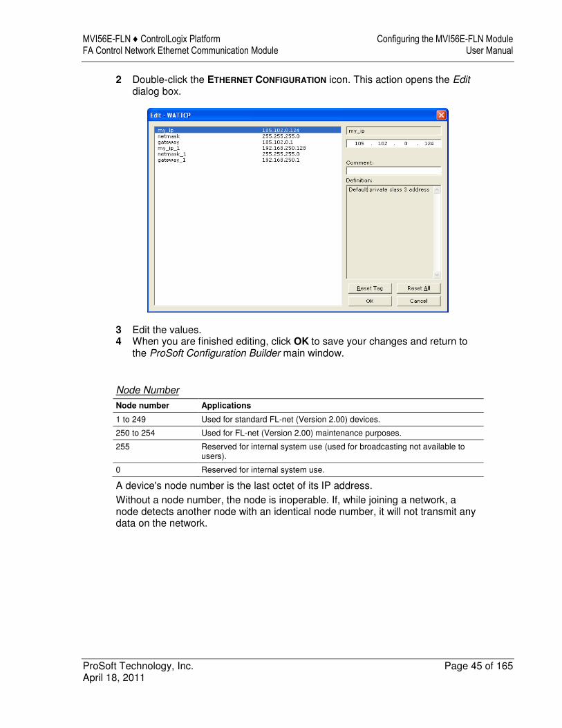
2 Double-click the ETHERNET CONFIGURATION icon. This action opens the Editdialog box.
3 Edit the values. 4 When you are finished editing, click OK to save your changes and return to
the ProSoft Configuration Builder main window.
Node Number
Node number Applications
1 to 249 Used for standard FL-net (Version 2.00) devices.
250 to 254 Used for FL-net (Version 2.00) maintenance purposes.
255 Reserved for internal system use (used for broadcasting not available to users).
0 Reserved for internal system use.
A device's node number is the last octet of its IP address.
Without a node number, the node is inoperable. If, while joining a network, a node detects another node with an identical node number, it will not transmit any data on the network.

Configuring the MVI56E-FLN Module MVI56E-FLN ♦ ControlLogix Platform User Manual FA Control Network Ethernet Communication Module
Page 46 of 165 ProSoft Technology, Inc. April 18, 2011
2.3 Downloading the Project to the Module
In order for the module to use the settings you configured, you must download (copy) the updated Project file from your PC to the module.
1 In the tree view in ProSoft Configuration Builder, click once to select the MVI56E-FLN module.
2 Open the PROJECT menu, and then choose MODULE / DOWNLOAD.
This action opens the Download dialog box. Notice that the Ethernet address field contains the IP address you assigned in the previous step or the temporary IP you assigned in the previous chapter. ProSoft Configuration Builder will use this IP or temporary IP address to connect to the module.
Click TEST CONNECTION to verify that the IP address is allows access to the module.
3 If the connection succeeds, click DOWNLOAD to transfer the Ethernet configuration to the module.

MVI56E-FLN ♦ ControlLogix Platform Configuring the MVI56E-FLN Module FA Control Network Ethernet Communication Module User Manual
ProSoft Technology, Inc. Page 47 of 165 April 18, 2011
If the Test Connection procedure fails, you will see an error message. To correct the error, follow these steps.
1 Click OK to dismiss the error message. 2 On the Download dialog box, click BROWSE DEVICES to open ProSoft
Discovery Service.
3 Select the module, and then click the right mouse button to open a shortcut menu. On the shortcut menu, choose SELECT FOR PCB.
4 Close ProSoft Discovery Service. 5 Click DOWNLOAD to transfer the configuration to the module.
Configuring the MVI56E-FLN Module MVI56E-FLN ♦ ControlLogix Platform User Manual FA Control Network Ethernet Communication Module
Page 48 of 165 ProSoft Technology, Inc. April 18, 2011
2.4 Configuring the FL-net Device
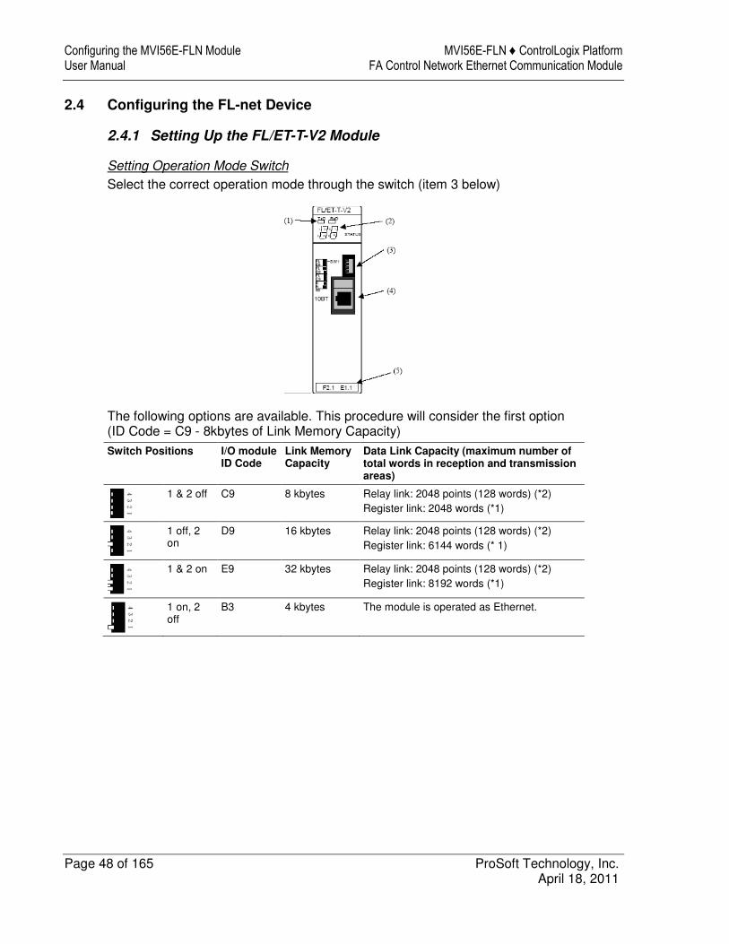
2.4.1 Setting Up the FL/ET-T-V2 Module
Setting Operation Mode Switch
Select the correct operation mode through the switch (item 3 below)
The following options are available. This procedure will consider the first option (ID Code = C9 - 8kbytes of Link Memory Capacity)
Switch Positions I/O module ID Code
Link Memory Capacity
Data Link Capacity (maximum number of total words in reception and transmission areas)
1 & 2 off C9 8 kbytes Relay link: 2048 points (128 words) (*2)
Register link: 2048 words (*1)
1 off, 2 on
D9 16 kbytes Relay link: 2048 points (128 words) (*2)
Register link: 6144 words (* 1)
1 & 2 on E9 32 kbytes Relay link: 2048 points (128 words) (*2)
Register link: 8192 words (*1)
1 on, 2 off
B3 4 kbytes The module is operated as Ethernet.

MVI56E-FLN ♦ ControlLogix Platform Configuring the MVI56E-FLN Module FA Control Network Ethernet Communication Module User Manual
ProSoft Technology, Inc. Page 49 of 165 April 18, 2011
2.4.2 FL/ET-V2 Configuration with PCwin
Specifying I/O Module ID Code
1 Expand the Parameter folder, and double-click I/O MODULE.

Configuring the MVI56E-FLN Module MVI56E-FLN ♦ ControlLogix Platform User Manual FA Control Network Ethernet Communication Module
Page 50 of 165 ProSoft Technology, Inc. April 18, 2011
2 Select the FL-net module.
Setting Up the FL/ET-V2 Link Parameters
1 Double-click LINK PARAMETER.

MVI56E-FLN ♦ ControlLogix Platform Configuring the MVI56E-FLN Module FA Control Network Ethernet Communication Module User Manual
ProSoft Technology, Inc. Page 51 of 165 April 18, 2011
2 Select the link number to assign to the FL/ET-T-V2 module. For this example, use Link No 1 for the FL/ET-T-V2 module. Double click the link row and configure the correct slot, rack and module for link 1 as shown in the following illustrations:
Configuring the MVI56E-FLN Module MVI56E-FLN ♦ ControlLogix Platform User Manual FA Control Network Ethernet Communication Module
Page 52 of 165 ProSoft Technology, Inc. April 18, 2011
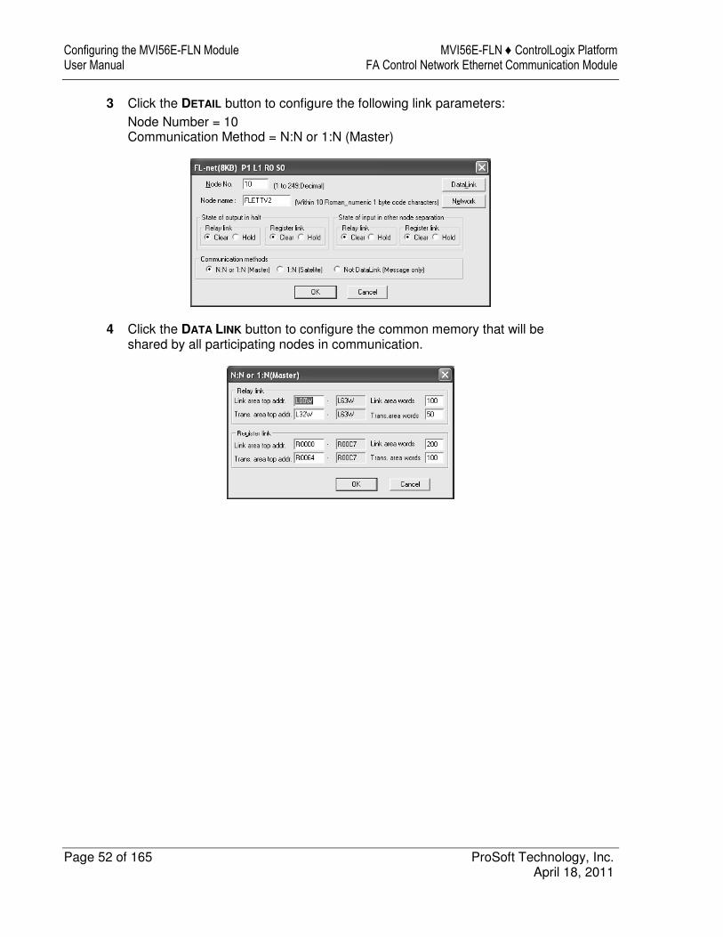
3 Click the DETAIL button to configure the following link parameters:
Node Number = 10 Communication Method = N:N or 1:N (Master)
4 Click the DATA LINK button to configure the common memory that will be shared by all participating nodes in communication.

MVI56E-FLN ♦ ControlLogix Platform Configuring the MVI56E-FLN Module FA Control Network Ethernet Communication Module User Manual
ProSoft Technology, Inc. Page 53 of 165 April 18, 2011
For this example, the data transfer takes place as described in the following illustration (the Transmit Area in the TOYODA PLC must be configured inside the Link Area):
5 Click OK to close the Data Link window, and then click the NETWORK button. Configure the default parameters as shown in the following illustration:
Note: This configuration sets the node address of the FL/ET-T-V2 module to 192.168.250.10 (the node address was configured as 10).

Configuring the MVI56E-FLN Module MVI56E-FLN ♦ ControlLogix Platform User Manual FA Control Network Ethernet Communication Module
Page 54 of 165 ProSoft Technology, Inc. April 18, 2011
For this example, the processor (rack 0 and slot 0) will be assigned as DLNK-M2. For more information about this topic, refer to the TOYODA PLC documentation.
2.4.3 Downloading the Project
Now save the project and download it to the TOYODA PLC.
2.4.4 Connecting the MVI56E-FLN Module to the FL/ET-T-V2
Use standard CA5 Ethernet cables to connect the Ethernet port on the MVI56E-FLN through a 10 Megabit Ethernet hub or switch to the Ethernet port on the FL/ET-T-V2 module.
Warning: The MVI56E-FLN module is NOT compatible with Power Over Ethernet (IEEE802.3af / IEEE802.3at) networks. Do NOT connect the module to Ethernet devices, hubs, switches or networks that supply AC or DC power over the Ethernet cable. Failure to observe this precaution may result in damage to hardware, or injury to personnel.

MVI56E-FLN ♦ ControlLogix Platform Configuring the MVI56E-FLN Module FA Control Network Ethernet Communication Module User Manual
ProSoft Technology, Inc. Page 55 of 165 April 18, 2011
2.5 Verifying Communication
This section shows how to monitor the communication status of the configured FL-net network (assuming that both the FL/ET-T-V2 module and the MVI56E-FLN module were configured according to the previous sections).
2.5.1 Using the Diagnostics Menu in ProSoft Configuration Builder
To connect to the module’s Configuration/Debug Ethernet port:
1 In ProSoft Configuration Builder, select the module, and then click the right mouse button to open a shortcut menu.
2 On the shortcut menu, choose DIAGNOSTICS.
This action opens the Diagnostics dialog box.

Configuring the MVI56E-FLN Module MVI56E-FLN ♦ ControlLogix Platform User Manual FA Control Network Ethernet Communication Module
Page 56 of 165 ProSoft Technology, Inc. April 18, 2011
If there is no response from the module:
1 Click the SET UP CONNECTION button to browse for the module’s IP address.
2 In the Connection Setup dialog box, click the TEST CONNECTION button to verify if the module is accessible with the current settings.

MVI56E-FLN ♦ ControlLogix Platform Configuring the MVI56E-FLN Module FA Control Network Ethernet Communication Module User Manual
ProSoft Technology, Inc. Page 57 of 165 April 18, 2011
If PCB is still unable to connect to the module:
1 Click the BROWSE DEVICE(S) button to open the ProSoft Discovery Service. Select the module, then right-click and choose SELECT FOR PCB.
2 Close ProSoft Discovery Service, and click the CONNECT button again. 3 If all of these troubleshooting steps fail, verify that the Ethernet cable is
connected properly between your computer and the module, either through a hub or switch (using a standard Ethernet cable) or directly between your computer and the module (using an Ethernet crossover-cable).
If you are still not able to establish a connection, contact ProSoft Technology for assistance.
Configuring the MVI56E-FLN Module MVI56E-FLN ♦ ControlLogix Platform User Manual FA Control Network Ethernet Communication Module
Page 58 of 165 ProSoft Technology, Inc. April 18, 2011
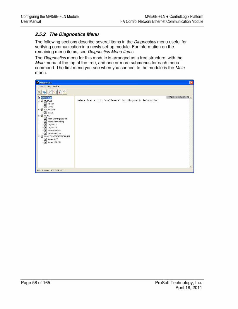
2.5.2 The Diagnostics Menu
The following sections describe several items in the Diagnostics menu useful for verifying communication in a newly set-up module. For information on the remaining menu items, see Diagnostics Menu Items.
The Diagnostics menu for this module is arranged as a tree structure, with the Main menu at the top of the tree, and one or more submenus for each menu command. The first menu you see when you connect to the module is the Main menu.
MVI56E-FLN ♦ ControlLogix Platform Configuring the MVI56E-FLN Module FA Control Network Ethernet Communication Module User Manual
ProSoft Technology, Inc. Page 59 of 165 April 18, 2011
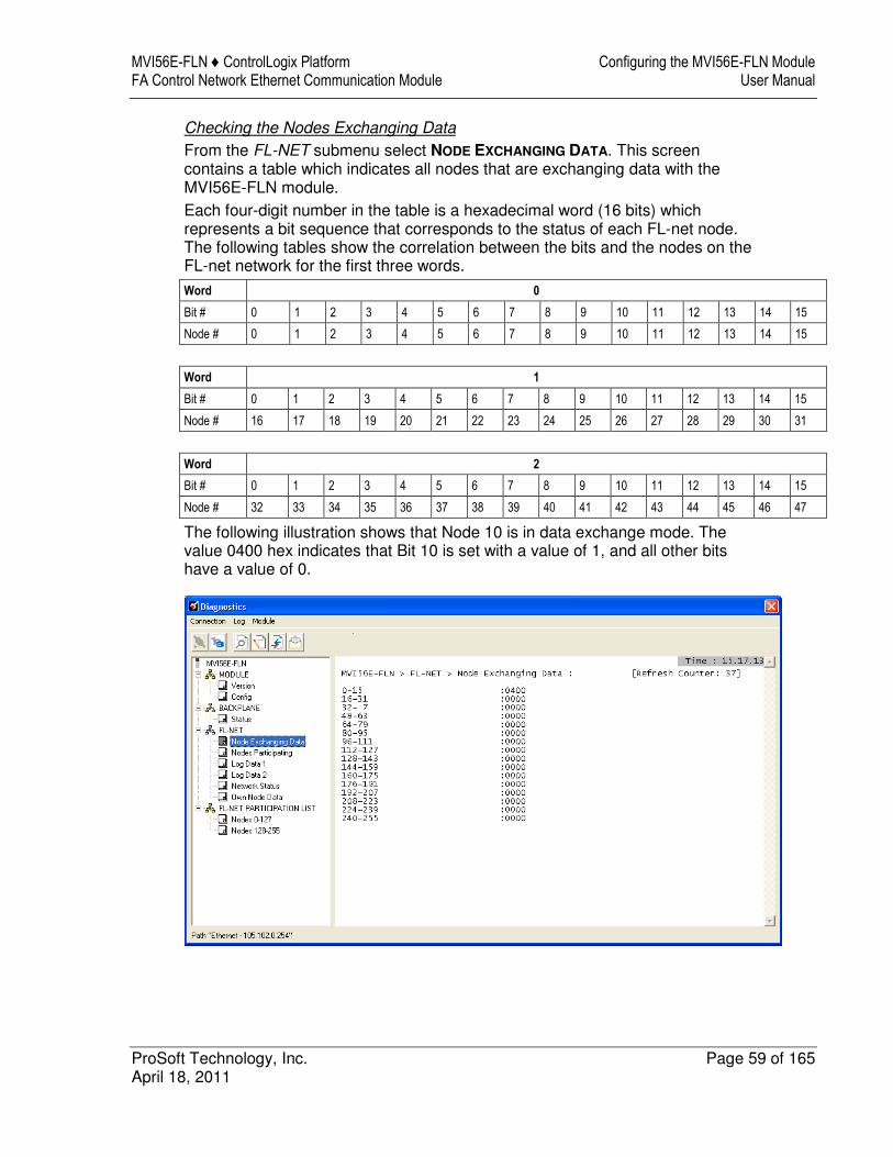
Checking the Nodes Exchanging Data
From the FL-NET submenu select NODE EXCHANGING DATA. This screen contains a table which indicates all nodes that are exchanging data with the MVI56E-FLN module.
Each four-digit number in the table is a hexadecimal word (16 bits) which represents a bit sequence that corresponds to the status of each FL-net node. The following tables show the correlation between the bits and the nodes on the FL-net network for the first three words.
Word 0
Bit # 0 1 2 3 4 5 6 7 8 9 10 11 12 13 14 15
Node # 0 1 2 3 4 5 6 7 8 9 10 11 12 13 14 15
Word 1
Bit # 0 1 2 3 4 5 6 7 8 9 10 11 12 13 14 15
Node # 16 17 18 19 20 21 22 23 24 25 26 27 28 29 30 31
Word 2
Bit # 0 1 2 3 4 5 6 7 8 9 10 11 12 13 14 15
Node # 32 33 34 35 36 37 38 39 40 41 42 43 44 45 46 47
The following illustration shows that Node 10 is in data exchange mode. The value 0400 hex indicates that Bit 10 is set with a value of 1, and all other bits have a value of 0.

Configuring the MVI56E-FLN Module MVI56E-FLN ♦ ControlLogix Platform User Manual FA Control Network Ethernet Communication Module
Page 60 of 165 ProSoft Technology, Inc. April 18, 2011
Checking the Participating Nodes
From the FL-NET submenu select NODES PARTICIPATING. This screen contains a table which indicates all participating nodes on the network.
Each four-digit number in the table is a hexadecimal word (16 bits) which represents a bit sequence that corresponds to the status of each FL-net node. The following tables show the correlation between the bits and the nodes on the FL-net network for the first three words.
Word 0
Bit # 0 1 2 3 4 5 6 7 8 9 10 11 12 13 14 15
Node # 0 1 2 3 4 5 6 7 8 9 10 11 12 13 14 15
Word 1
Bit # 0 1 2 3 4 5 6 7 8 9 10 11 12 13 14 15
Node # 16 17 18 19 20 21 22 23 24 25 26 27 28 29 30 31
Word 2
Bit # 0 1 2 3 4 5 6 7 8 9 10 11 12 13 14 15
Node # 32 33 34 35 36 37 38 39 40 41 42 43 44 45 46 47
The following illustration shows that Nodes 10 and 40 are participating; a value of 0400 hex in Word 0 indicates that Bit 10 is set with a value of 1 and a value of 0100 hex in Word 2 indicates that Bit 40 is set with a value of 1.

MVI56E-FLN ♦ ControlLogix Platform Configuring the MVI56E-FLN Module FA Control Network Ethernet Communication Module User Manual
ProSoft Technology, Inc. Page 61 of 165 April 18, 2011
Checking the Log Data
From the FL-NET submenu select LOG DATA 1 or LOG DATA 2 to display information pertaining to:
� Transmission � Reception � Cyclic Transmission

Configuring the MVI56E-FLN Module MVI56E-FLN ♦ ControlLogix Platform User Manual FA Control Network Ethernet Communication Module
Page 62 of 165 ProSoft Technology, Inc. April 18, 2011
Checking the Network Status
From the FL-NET submenu select NETWORK STATUS to display network information:
� Token-holding node number � Minimum Frame Interval Time � Refresh Cycle Time � Refresh Cycle Measurement Time
MVI56E-FLN ♦ ControlLogix Platform Configuring the MVI56E-FLN Module FA Control Network Ethernet Communication Module User Manual
ProSoft Technology, Inc. Page 63 of 165 April 18, 2011
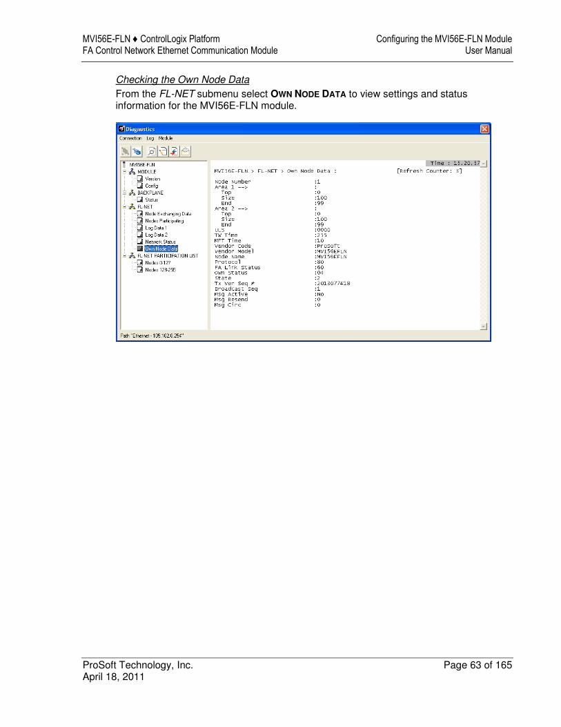
Checking the Own Node Data
From the FL-NET submenu select OWN NODE DATA to view settings and status information for the MVI56E-FLN module.

Configuring the MVI56E-FLN Module MVI56E-FLN ♦ ControlLogix Platform User Manual FA Control Network Ethernet Communication Module
Page 64 of 165 ProSoft Technology, Inc. April 18, 2011
Checking the Participating Node Status
From the FLN-NET PARTICIPATION LIST submenu select NODES 0-127 and NODES 128-255 to view settings and status information for each participating node on the network.
MVI56E-FLN ♦ ControlLogix Platform Configuring the MVI56E-FLN Module FA Control Network Ethernet Communication Module User Manual
ProSoft Technology, Inc. Page 65 of 165 April 18, 2011
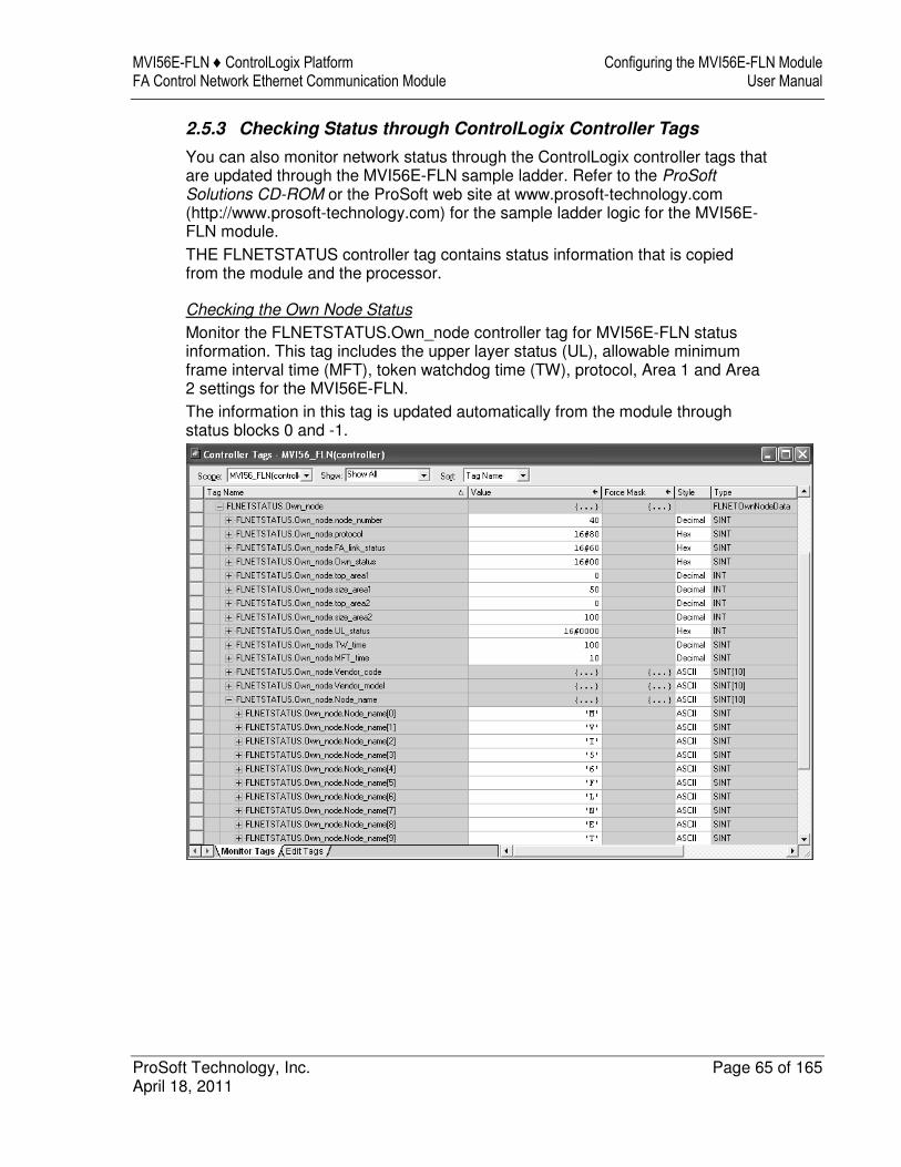
2.5.3 Checking Status through ControlLogix Controller Tags
You can also monitor network status through the ControlLogix controller tags that are updated through the MVI56E-FLN sample ladder. Refer to the ProSoft Solutions CD-ROM or the ProSoft web site at www.prosoft-technology.com (http://www.prosoft-technology.com) for the sample ladder logic for the MVI56E-FLN module.
THE FLNETSTATUS controller tag contains status information that is copied from the module and the processor.
Checking the Own Node Status
Monitor the FLNETSTATUS.Own_node controller tag for MVI56E-FLN status information. This tag includes the upper layer status (UL), allowable minimum frame interval time (MFT), token watchdog time (TW), protocol, Area 1 and Area 2 settings for the MVI56E-FLN.
The information in this tag is updated automatically from the module through status blocks 0 and -1.

Configuring the MVI56E-FLN Module MVI56E-FLN ♦ ControlLogix Platform User Manual FA Control Network Ethernet Communication Module
Page 66 of 165 ProSoft Technology, Inc. April 18, 2011
Checking the Nodes Exchanging Data
Monitor the FLNETSTATUS.General.Nodes_Exchanging_Data_Table[ ] controller tag to see if each node is currently exchanging data. The following illustration shows that only node 10 is currently exchanging data with the MVI56E-FLN module: bit 10 of FLNETSTATUS.General.Nodes_Exchanging_Data_Table[0] word is set to 1 (hex value of 0400). The information in this tag is updated automatically from the module through status blocks 0 and -1.

MVI56E-FLN ♦ ControlLogix Platform Configuring the MVI56E-FLN Module FA Control Network Ethernet Communication Module User Manual
ProSoft Technology, Inc. Page 67 of 165 April 18, 2011
Checking the Participation Table
Monitor the FLNETSTATUS.General.Nodes_Participating_Count controller tag to see the number of nodes currently participating in the network. The information in this tag is updated automatically from the module through status blocks 0 and -1.
Monitor the FLNETSTATUS.General.Nodes_Participating_Table[ ] controller tag to check if each node is currently participating in the FL-net network. The following illustration shows that only nodes 10 and 40 are participating.
� Bit 10 of FLNETSTATUS.General.Nodes_Exchanging_Data_Table[0] word is set as 1 (hex value of 0400)
� Bit 8 of FLNETSTATUS.General.Nodes_Exchanging_Data_Table[2] word is set as 1 (hex value of 0100).
� Bit 8 of FLNETSTATUS.General.Nodes_Exchanging_Data_Table[2] corresponds with bit 40 for the entire participating table.
The following illustration shows that currently there are 2 nodes participating.
Configuring the MVI56E-FLN Module MVI56E-FLN ♦ ControlLogix Platform User Manual FA Control Network Ethernet Communication Module
Page 68 of 165 ProSoft Technology, Inc. April 18, 2011
Checking the Participating Node Status
To retrieve the participation node status, the processor must request special block 2000 (Participation Table Request) from the module. This special block transfer request allows the processor to retrieve status information for each participating node. Status registers include:
� upper layer status (ULS) � allowable minimum frame interval time (MFT) � allowable refresh cycle time (RCT) � Area 1 (A1) and Area 2 (A2) settings � token watchdog time (TW).
Each block can retrieve status for up to 10 participating nodes. The user application must initially select the number of nodes to retrieve (up to 10) and the first node address to retrieve.
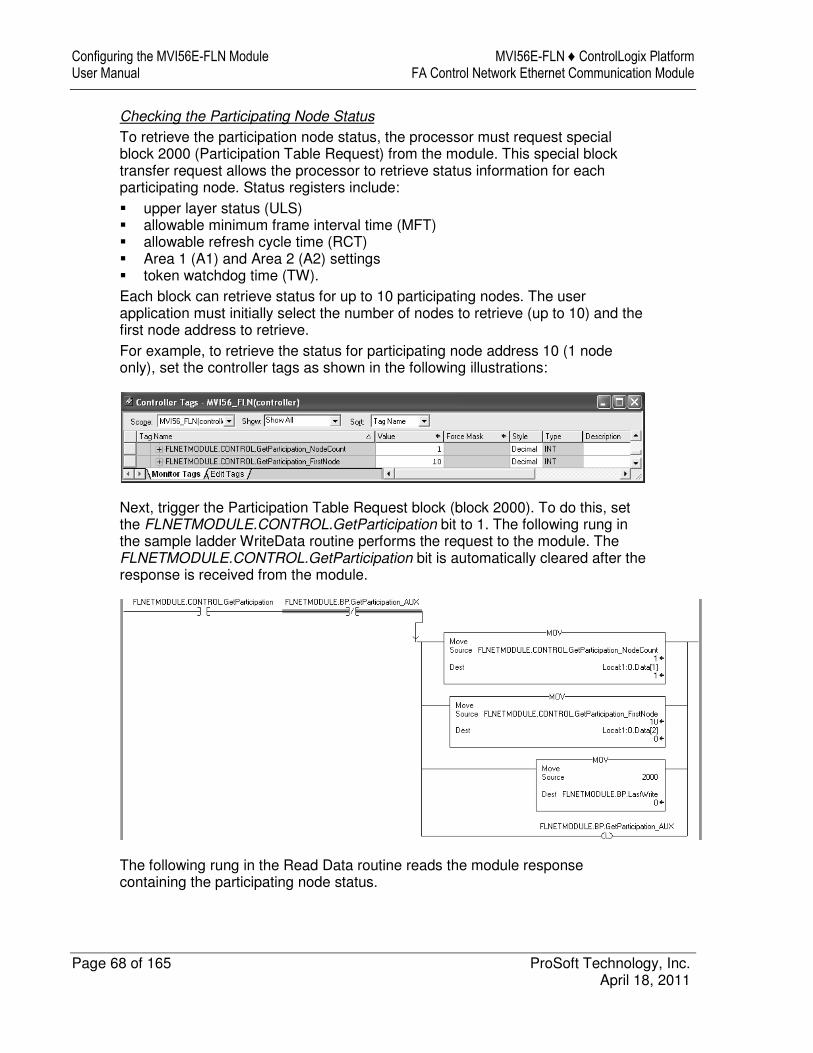
For example, to retrieve the status for participating node address 10 (1 node only), set the controller tags as shown in the following illustrations:
Next, trigger the Participation Table Request block (block 2000). To do this, set the FLNETMODULE.CONTROL.GetParticipation bit to 1. The following rung in the sample ladder WriteData routine performs the request to the module. The FLNETMODULE.CONTROL.GetParticipation bit is automatically cleared after the response is received from the module.
The following rung in the Read Data routine reads the module response containing the participating node status.

MVI56E-FLN ♦ ControlLogix Platform Configuring the MVI56E-FLN Module FA Control Network Ethernet Communication Module User Manual
ProSoft Technology, Inc. Page 69 of 165 April 18, 2011
Note: The sample ladder will copy the status for 10 nodes. Edit this logic according to the number of nodes to be read for your application.

Configuring the MVI56E-FLN Module MVI56E-FLN ♦ ControlLogix Platform User Manual FA Control Network Ethernet Communication Module
Page 70 of 165 ProSoft Technology, Inc. April 18, 2011
The participating node status is read to the FLNETSTATUS.Participation[ ] controller tag array. The status for node address 10 is available at FLNETSTATUS.Participation[0].

MVI56E-FLN ♦ ControlLogix Platform Configuring the MVI56E-FLN Module FA Control Network Ethernet Communication Module User Manual
ProSoft Technology, Inc. Page 71 of 165 April 18, 2011
Checking the Log Data
To retrieve the Log Data, the processor must request special block 9250 (Log Data Block) from the module.
The following rung in the Write Data routine requests block 9250. To trigger this logic, set the FLNETMODULE.CONTROL.GetParticipation bit to 1.
The processor will eventually receive the block response from the module, and the following rung in the Write Data routine will automatically clear the FLNETMODULE.CONTROL.GetParticipation bit and read the block response to the correct tags.

Configuring the MVI56E-FLN Module MVI56E-FLN ♦ ControlLogix Platform User Manual FA Control Network Ethernet Communication Module
Page 72 of 165 ProSoft Technology, Inc. April 18, 2011
You can view the Log Data read from the module in the FLNETSTATUS.LogData controller tag, as shown in the following illustration:

MVI56E-FLN ♦ ControlLogix Platform Configuring the MVI56E-FLN Module FA Control Network Ethernet Communication Module User Manual
ProSoft Technology, Inc. Page 73 of 165 April 18, 2011
Checking the General Network Status
Monitor the FLNETSTATUS.Network for general FL-net network information:
� the token node that is currently holding the token � the refresh cycle measurement time (RMT) - minimum, maximum and current
values � allowable minimum frame interval time (MFT) � allowable refresh cycle time (RCT).
This information is available in the FLNETSTATUS.Network controller tag.
Checking the Backplane status
Monitor the FLNETSTATUS.Backplane controller tag for information about backplane status.

Configuring the MVI56E-FLN Module MVI56E-FLN ♦ ControlLogix Platform User Manual FA Control Network Ethernet Communication Module
Page 74 of 165 ProSoft Technology, Inc. April 18, 2011
2.5.4 Transferring Data
The sample ladder logic automatically updates the data with the FLNETDATA.Output and FLNETDATA.Input controller tags. The Area 1 data is divided into blocks 1 to 3. The Area 2 data is divided into blocks 4 to 35. Each block contains up to 240 words of data.
The data received from the remote FL-net node to the MVI56E-FLN module is automatically "reassembled" from the input blocks into the FLNETDATA.Intput controller tag (according to each block ID). Also, the data to transfer from the module to the remote FL-net node is copied from the FLNETDATA.Output controller tag into the output blocks according to its block ID. This logic is already handled by the sample ladder program supplied by ProSoft.
For this example, use the following MVI56E-FLN Area1 and Area 2 settings in the FLNET.CFG configuration file:
Area 1 Top : 0 #0...511 top address for area 1
Area 1 Size : 50 #0...512 area 1 data size in words (0=not used)
Area 2 Top : 0 #0...8191 top address for area 1
Area 2 Size : 100 #0...8192 area 2 data size in words (0=not used)
BP Area 1 Top : 50 #0...511 top address for area 1
BP Area 1 Size: 50 #0...512 area 1 data size in words (0=none transferred)
BP Area 2 Top : 100 #0...8191 top address for area 1
BP Area 2 Size: 100 #0...8192 area 2 data size in words (0=none transferred)
Important: The module only generates the blocks required to transfer the data you configured. For this example only one Area 1 block and one Area 2 blocks are required, so only blocks 1 to 4 are used for data transfer. The larger the areas, the more blocks are required to transfer data (and the more time is required to update the whole block).
In this example, configure the FL/ET-T-V2 module with the values in the following illustration:

MVI56E-FLN ♦ ControlLogix Platform Configuring the MVI56E-FLN Module FA Control Network Ethernet Communication Module User Manual
ProSoft Technology, Inc. Page 75 of 165 April 18, 2011
Transferring Data from MVI56E-FLN (Area 1) to FL/ET-T-V2 Module (Relay Area)
The FLNETDATA.Output.Area1 controller tags transfer data from the module Area 1 to the remote FL-net node Relay link area. For this example, use the values in the following illustration:
Use the PCWin Register Address Monitor to monitor the value set by the module (address L00W for our example).

Configuring the MVI56E-FLN Module MVI56E-FLN ♦ ControlLogix Platform User Manual FA Control Network Ethernet Communication Module
Page 76 of 165 ProSoft Technology, Inc. April 18, 2011
Transferring Data from FL/ET-T-V2 Link Area to MVI56E-FLN Area 1
Use the PCWin Register Address Monitor to set the value to transfer to the module (address L32W for this example)
Use FLNETDATA.Input.Area1 controller tags to monitor data received from the remote node to the MVI56E-FLN Area 1.

MVI56E-FLN ♦ ControlLogix Platform Configuring the MVI56E-FLN Module FA Control Network Ethernet Communication Module User Manual
ProSoft Technology, Inc. Page 77 of 165 April 18, 2011
Transferring Data from MVI56E-FLN (Area 2) to FL/ET-T-V2 module (Register Area)
Use the FLNETDATA.Output.Area2 controller tags to transfer data from the module Area 1 to the remote FL-net node Relay link area. For this example, use the values in the following illustration:
Use the PCWin Register Address Monitor to monitor the value set by the module (address R000 for our example).

Configuring the MVI56E-FLN Module MVI56E-FLN ♦ ControlLogix Platform User Manual FA Control Network Ethernet Communication Module
Page 78 of 165 ProSoft Technology, Inc. April 18, 2011
Transferring Data from FL/ET-T-V2 Register Area to MVI56E-FLN Area 2
Use the PCWin Register Address Monitor to set the value to transfer to the module (address R0064 for this example)
Use the FLNETDATA.Input.Area2 controller tags to monitor data received from the remote node to the MVI56E-FLN Area 2.
MVI56E-FLN ♦ ControlLogix Platform Diagnostics and Troubleshooting FA Control Network Ethernet Communication Module User Manual
ProSoft Technology, Inc. Page 79 of 165 April 18, 2011
3 Diagnostics and Troubleshooting
In This Chapter
� Reading Status Data from the Module .................................................. 79
� Diagnostics Menu Items ........................................................................ 82
� LED Status Indicators ............................................................................ 85
� Clearing a Fault Condition ..................................................................... 88
� Troubleshooting ..................................................................................... 89
The module provides information on diagnostics and troubleshooting in the following forms:
� LED status indicators on the front of the module provide information on the module’s status.
� Status data contained in the module can be viewed in ProSoft Configuration Builder through the Ethernet port.
� Status data values are transferred from the module to the processor.
3.1 Reading Status Data from the Module
The MVI56E-FLN module returns a block of status data in the input image that can be used to determine the module’s operating status. This data is transferred from the module to the ControlLogix processor continuously. You can view this data in the FLN.STATUS controller tag in the ladder logic.
If the Error/Status Pointer is enabled, the status data can also be found in the Read Data area of the module’s database at a location specified by the Error/Status Pointer configuration parameter.
The Configuration/Debug port provides the following functionality:
� Full view of the module’s configuration data � View of the module’s status data � Version Information � Control over the module (warm boot, cold boot, transfer configuration) � Facility to upload and download the module’s configuration file
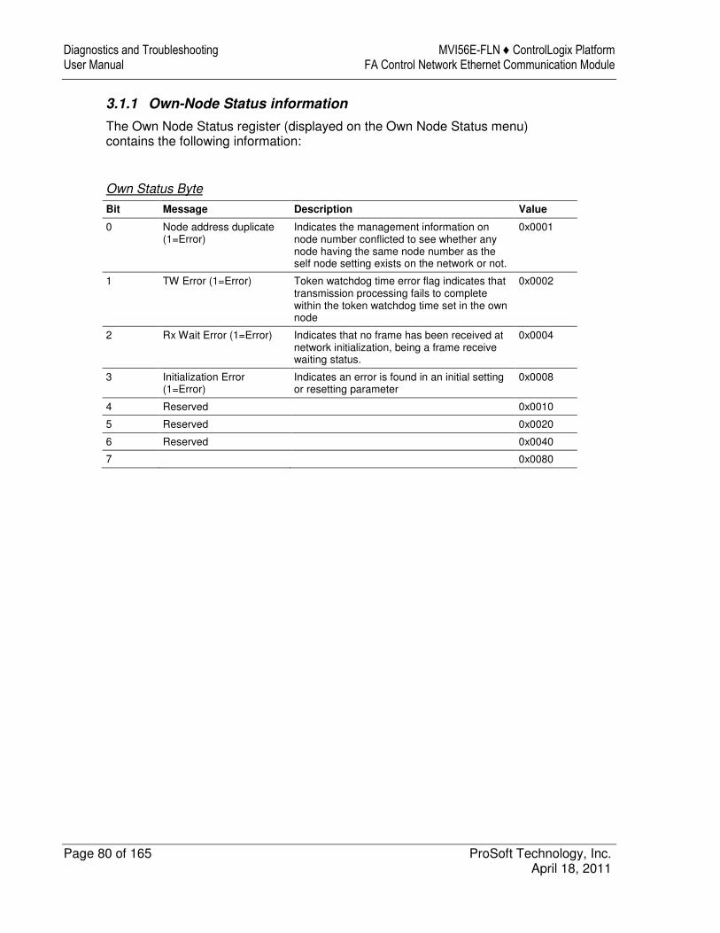
Diagnostics and Troubleshooting MVI56E-FLN ♦ ControlLogix Platform User Manual FA Control Network Ethernet Communication Module
Page 80 of 165 ProSoft Technology, Inc. April 18, 2011
3.1.1 Own-Node Status information
The Own Node Status register (displayed on the Own Node Status menu) contains the following information:
Own Status Byte
Bit Message Description Value
0 Node address duplicate (1=Error)
Indicates the management information on node number conflicted to see whether any node having the same node number as the self node setting exists on the network or not.
0x0001
1 TW Error (1=Error) Token watchdog time error flag indicates that transmission processing fails to complete within the token watchdog time set in the own node
0x0002
2 Rx Wait Error (1=Error) Indicates that no frame has been received at network initialization, being a frame receive waiting status.
0x0004
3 Initialization Error (1=Error)
Indicates an error is found in an initial setting or resetting parameter
0x0008
4 Reserved 0x0010
5 Reserved 0x0020
6 Reserved 0x0040
7 0x0080
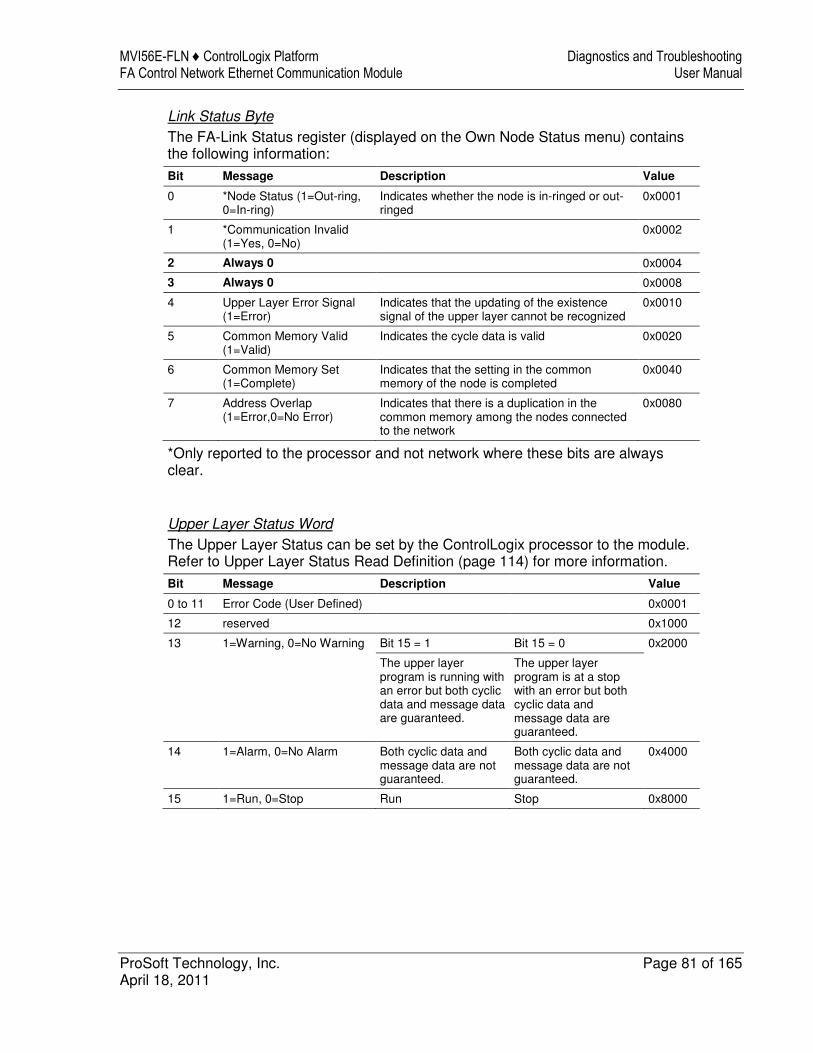
MVI56E-FLN ♦ ControlLogix Platform Diagnostics and Troubleshooting FA Control Network Ethernet Communication Module User Manual
ProSoft Technology, Inc. Page 81 of 165 April 18, 2011
Link Status Byte
The FA-Link Status register (displayed on the Own Node Status menu) contains the following information:
Bit Message Description Value
0 *Node Status (1=Out-ring, 0=In-ring)
Indicates whether the node is in-ringed or out-ringed
0x0001
1 *Communication Invalid (1=Yes, 0=No)
0x0002
2 Always 0 0x0004
3 Always 0 0x0008
4 Upper Layer Error Signal (1=Error)
Indicates that the updating of the existence signal of the upper layer cannot be recognized
0x0010
5 Common Memory Valid (1=Valid)
Indicates the cycle data is valid 0x0020
6 Common Memory Set (1=Complete)
Indicates that the setting in the common memory of the node is completed
0x0040
7 Address Overlap (1=Error,0=No Error)
Indicates that there is a duplication in the common memory among the nodes connected to the network
0x0080
*Only reported to the processor and not network where these bits are always clear.
Upper Layer Status Word
The Upper Layer Status can be set by the ControlLogix processor to the module. Refer to Upper Layer Status Read Definition (page 114) for more information.
Bit Message Description Value
0 to 11 Error Code (User Defined) 0x0001
12 reserved 0x1000
13 1=Warning, 0=No Warning Bit 15 = 1 Bit 15 = 0 0x2000
The upper layer program is running with an error but both cyclic data and message data are guaranteed.
The upper layer program is at a stop with an error but both cyclic data and message data are guaranteed.
14 1=Alarm, 0=No Alarm Both cyclic data and message data are not guaranteed.
Both cyclic data and message data are not guaranteed.
0x4000
15 1=Run, 0=Stop Run Stop 0x8000

Diagnostics and Troubleshooting MVI56E-FLN ♦ ControlLogix Platform User Manual FA Control Network Ethernet Communication Module
Page 82 of 165 ProSoft Technology, Inc. April 18, 2011
3.2 Diagnostics Menu Items
This section describes PCB Diagnostics menu items that were not addressed in the chapter on Configuring the MVI56E-FLN Module. For general information on accessing the Diagnostics menu, please refer to Using the Diagnostic Menu in Prosoft Configuration Builder. For specific information on items in the FL-NET submenu, please see The Diagnostics Menu (page 58).
3.2.1 Monitoring Module Information
Use the MODULE menu to view configuration and hardware information for the MVI56E-FLN module’s backplane and Ethernet application port.
Viewing Version Information
From the MODULE submenu select VERSION to view module hardware and firmware information.
The values on this menu correspond with the contents of the module’s general product information registers.

MVI56E-FLN ♦ ControlLogix Platform Diagnostics and Troubleshooting FA Control Network Ethernet Communication Module User Manual
ProSoft Technology, Inc. Page 83 of 165 April 18, 2011
Viewing Configuration Information
From the MODULE submenu select CONFIG to view backplane configuration settings for the MVI56E-FLN module.
This information corresponds with the FL-NET configuration settings in ProSoft Configuration Builder (page 40).

Diagnostics and Troubleshooting MVI56E-FLN ♦ ControlLogix Platform User Manual FA Control Network Ethernet Communication Module
Page 84 of 165 ProSoft Technology, Inc. April 18, 2011
3.2.2 Monitoring Backplane Information
Use the BACKPLANE menu to view the backplane status information for the MVI56E-FLN module.
Viewing Backplane Status
From the BACKPLANE submenu select STATUS to view current backplane status, including
� Number of retries � Backplane Status � Fail Count � Number of words read � Number of words written � Number of words parsed � Error count � Event count � Command count
During normal operation, the Read, Write, and Parsing values should increment continuously, while the error value should not increment.
The status values on this menu correspond with the members of the MVI56E-FLN Status object.
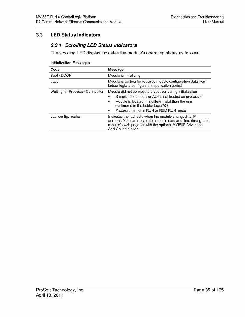
MVI56E-FLN ♦ ControlLogix Platform Diagnostics and Troubleshooting FA Control Network Ethernet Communication Module User Manual
ProSoft Technology, Inc. Page 85 of 165 April 18, 2011
3.3 LED Status Indicators
3.3.1 Scrolling LED Status Indicators
The scrolling LED display indicates the module's operating status as follows:
Initialization Messages
Code Message
Boot / DDOK Module is initializing
Ladd Module is waiting for required module configuration data from ladder logic to configure the application port(s)
Waiting for Processor Connection Module did not connect to processor during initialization
� Sample ladder logic or AOI is not loaded on processor
� Module is located in a different slot than the oneconfigured in the ladder logic/AOI
� Processor is not in RUN or REM RUN mode
Last config: <date> Indicates the last date when the module changed its IP address. You can update the module date and time through the module’s web page, or with the optional MVI56E Advanced Add-On Instruction.
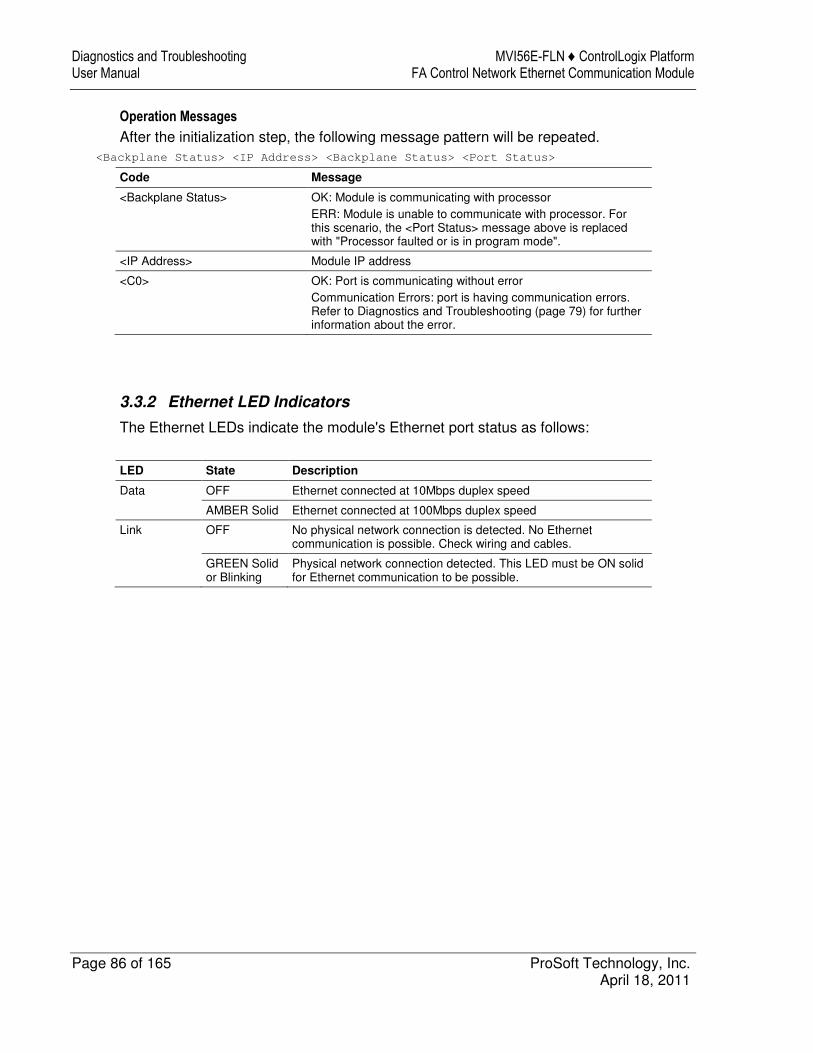
Diagnostics and Troubleshooting MVI56E-FLN ♦ ControlLogix Platform User Manual FA Control Network Ethernet Communication Module
Page 86 of 165 ProSoft Technology, Inc. April 18, 2011
Operation Messages
After the initialization step, the following message pattern will be repeated.
<Backplane Status> <IP Address> <Backplane Status> <Port Status>
Code Message
<Backplane Status> OK: Module is communicating with processor
ERR: Module is unable to communicate with processor. For this scenario, the <Port Status> message above is replaced with "Processor faulted or is in program mode".
<IP Address> Module IP address
<C0> OK: Port is communicating without error
Communication Errors: port is having communication errors. Refer to Diagnostics and Troubleshooting (page 79) for further information about the error.
3.3.2 Ethernet LED Indicators
The Ethernet LEDs indicate the module's Ethernet port status as follows:
LED State Description
Data OFF Ethernet connected at 10Mbps duplex speed
AMBER Solid Ethernet connected at 100Mbps duplex speed
Link OFF No physical network connection is detected. No Ethernet communication is possible. Check wiring and cables.
GREEN Solid or Blinking
Physical network connection detected. This LED must be ON solid for Ethernet communication to be possible.
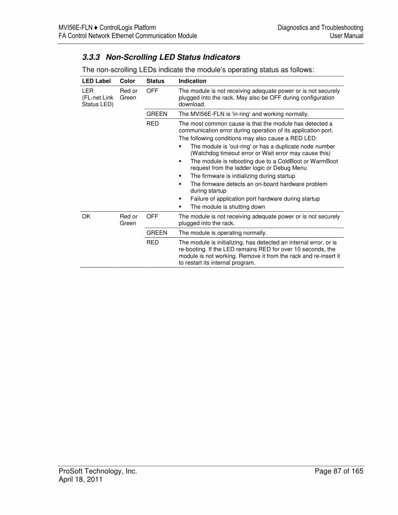
MVI56E-FLN ♦ ControlLogix Platform Diagnostics and Troubleshooting FA Control Network Ethernet Communication Module User Manual
ProSoft Technology, Inc. Page 87 of 165 April 18, 2011
3.3.3 Non-Scrolling LED Status Indicators
The non-scrolling LEDs indicate the module’s operating status as follows:
LED Label Color Status Indication
LER (FL-net Link Status LED)
Red or Green
OFF The module is not receiving adequate power or is not securely plugged into the rack. May also be OFF during configuration download.
GREEN The MVI56E-FLN is 'in-ring' and working normally.
RED The most common cause is that the module has detected a communication error during operation of its application port.
The following conditions may also cause a RED LED:
� The module is 'out-ring' or has a duplicate node number (Watchdog timeout error or Wait error may cause this)
� The module is rebooting due to a ColdBoot or WarmBoot request from the ladder logic or Debug Menu
� The firmware is initializing during startup
� The firmware detects an on-board hardware problem during startup
� Failure of application port hardware during startup
� The module is shutting down
OK Red or Green
OFF The module is not receiving adequate power or is not securely plugged into the rack.
GREEN The module is operating normally.
RED The module is initializing, has detected an internal error, or is re-booting. If the LED remains RED for over 10 seconds, the module is not working. Remove it from the rack and re-insert it to restart its internal program.

Diagnostics and Troubleshooting MVI56E-FLN ♦ ControlLogix Platform User Manual FA Control Network Ethernet Communication Module
Page 88 of 165 ProSoft Technology, Inc. April 18, 2011
3.4 Clearing a Fault Condition
Typically, if the OK LED on the front of the module turns RED for more than ten seconds, a hardware problem has been detected in the module or the program has exited.
To clear the condition, follow these steps:
1 Turn off power to the rack. 2 Remove the card from the rack. 3 Verify that all jumpers are set correctly. 4 If the module requires a Compact Flash card, verify that the card is installed
correctly. 5 Re-insert the card in the rack and turn the power back on. 6 Verify correct configuration data is being transferred to the module from the
ControlLogix controller.
If the module's OK LED does not turn GREEN, verify that the module is inserted completely into the rack. If this does not cure the problem, contact ProSoft Technology Technical Support.

MVI56E-FLN ♦ ControlLogix Platform Diagnostics and Troubleshooting FA Control Network Ethernet Communication Module User Manual
ProSoft Technology, Inc. Page 89 of 165 April 18, 2011
3.5 Troubleshooting
Use the following troubleshooting steps if you encounter problems when the module is powered up. If these steps do not resolve your problem, please contact ProSoft Technology Technical Support.
Processor Errors
Problem Description Steps to take
Processor Fault Verify that the module is plugged into the slot that has been configured for the module in the I/O Configuration of RSLogix.
Verify that the slot location in the rack has been configured correctly in the ladder logic.
Processor I/O LED flashes
This indicates a problem with backplane communications. A problem could exist between the processor and any installed I/O module, not just the MVI56E-FLN. Verify that all modules in the rack are correctly configured in the ladder logic.
Module Errors
Problem Description Steps to take
MVI56E modules with scrolling LED display: <Backplane Status> condition reads ERR
This indicates that backplane transfer operations are failing. Connect to the module’s Configuration/Debug port to check this.
To establish backplane communications, verify the following items:
� The processor is in RUN or REM RUN mode.
� The backplane driver is loaded in the module.
� The module is configured for read and write data block transfer.
� The ladder logic handles all read and write block situations.
� The module is properly configured in the processor I/O configuration and ladder logic.
OK LED remains RED The program has halted or a critical error has occurred. Connect to the Configuration/Debug port to see if the module is running. If the program has halted, turn off power to the rack, remove the card from the rack and re-insert the card in the rack, and then restore power to the rack.

Diagnostics and Troubleshooting MVI56E-FLN ♦ ControlLogix Platform User Manual FA Control Network Ethernet Communication Module
Page 90 of 165 ProSoft Technology, Inc. April 18, 2011
MVI56E-FLN ♦ ControlLogix Platform Reference FA Control Network Ethernet Communication Module User Manual
ProSoft Technology, Inc. Page 91 of 165 April 18, 2011
4 Reference
In This Chapter
� Product Specifications ........................................................................... 91
� Functional Overview .............................................................................. 95
� Implementation of FL-net..................................................................... 110
� FL-net Protocol and Network ............................................................... 120
� Error and Status Data .......................................................................... 132
� FL-net Device Profile for MVI56E-FLN Module ................................... 133
� Module Power Up ................................................................................ 136
� State Transition Diagram ..................................................................... 136
� Cable Connections - MVI56E-FLN ...................................................... 146
4.1 Product Specifications
The MVI56E-FLN FA Control Network communication module is a single slot solution that allows Rockwell Automation ControlLogix compatible processors to easily interface with other FL-net protocol compatible devices. The module implements FL-net version 2.00 (OPCN-2) defined by JEMA (The Japan Electrical Manufacturers Association) for the standard FA control network. FL-net is a master-less system.
The MVI56E-FLN module acts as a gateway between the FL-net network and the ControlLogix backplane. The data transfer from the ControlLogix processor is asynchronous from the actions on the FL-net network. The module’s internal database can be used to exchange Area 1 and Area 2 cyclic, network, and module status data between the processor and the FL-net network.
The MVI56E-FLN module accepts commands to control and monitor the data stored in the databases. This data is passed between the module and the ControlLogix processor over the backplane for use in user applications.
General features include:
� Master-less token control method � FA link protocol on Ethernet UDP/IP � Cyclic data transfer: Supports virtual memory Area 1 and Area 2. The cyclic
data is mapped to the modules I/O area
Reference MVI56E-FLN ♦ ControlLogix Platform User Manual FA Control Network Ethernet Communication Module
Page 92 of 165 ProSoft Technology, Inc. April 18, 2011
4.1.1 Features
FL-net systems have the following features.
1 FL-net is an open system. 2 FL-net enables a multi-vendor network. 3 FL-net enables personal computers and FA controllers, such as
programmable controllers (PLCs) or computerized numeric controllers (CNCs), by different manufacturers to be interconnected, controlled, and monitored.
� Master-less token control method. � FA link protocol on Ethernet UDP / IP. � Cyclic data transfer: Supports virtual memory Area 1 (512 words) and Area 2
(8192 words). The cyclic data is mapped to the modules I/O area. � Message transfer:
Server Functionality
o Log data read service o Log data clear service o Network Parameter Read o Profile Read o Return Message
� Network Management Table: According to FL-net version 2.00 specification. � Own-node Management Table: According to FL-net version 2.00
specification. � Participating Node Management Table: According to FL-net version 2.00
specification. � Network configurable via a text file or ProSoft Technology Configuration
Builder Software � Status and Error information
The MVI56E-FLN module provides highly configurable FL-net capabilities to the Allen-Bradley ControlLogix platform. FL-net (OPCN-2) is a controller-level network conforming to specification Japan Electrical manufacturers Association JEM1479. Developed by to focus on multi-vendor communications of programmable controllers, NC controllers, Robotic and other Motion Control systems.

MVI56E-FLN ♦ ControlLogix Platform Reference FA Control Network Ethernet Communication Module User Manual
ProSoft Technology, Inc. Page 93 of 165 April 18, 2011
4.1.2 General Specifications
� Backward compatible with previous MVI56-FLN versions � Single-slot 1756 ControlLogix backplane compatible � 10/100 Mbps auto crossover detection Ethernet configuration and application
port � User-definable module data memory mapping of up to 5000 16-bit registers � ProSoft Configuration Builder (PCB) software supported, a Winows-based
graphical user interface providing simple product and network configuration � Sample ladder logic is used for data transfer between module and processor � Internal web server provides access to product documentation, module
status, diagnostics, and firmware updates � 4-character, alpha-numeric, scrolling LED display of status and diagnostics
data in plain English – no cryptic error or alarm codes to decipher � ProSoft Discovery Service (PDS) software used to locate the module on the
network and assign temporary IP address � Personality Module - a non-volatile industrial-grade Compact Flash (CF) card
used to store network and module configuration, allowing quick in-the-field product replacement by transferring the CF card
4.1.3 Hardware Specifications
Specification Description
Backplane Current Load 800 mA @ 5 Vdc 3 mA @ 24 Vdc
Operating Temperature 0°C to 60°C (32°F to 140°F)
Storage Temperature -40°C to 85°C (-40°F to 185°F)
Shock 30 g operational 50 g non-operational Vibration: 5 g from 10 to 150 Hz
Relative Humidity 5% to 95% (without condensation)
LED Indicators Battery Status (ERR) Application Status (APP) Module Status (OK)
4-Character, Scrolling, Alpha-Numeric LED Display
Shows Module, Version, IP, Application Port Setting, Port Status, and Error Information
Debug/Configuration Ethernet port (E1)
Ethernet Port 10/100 Base-T, RJ45 Connector, for CAT5 cable
Link and Activity LED indicators
Auto-crossover cable detection
FL-net Application Ethernet port (E2)
Ethernet Port 10 base-T, RJ45 Connector, for CAT5 cable
Link and Activity LED indicators
Auto-crossover cable detection
Shipped with Unit Two, 5-foot Ethernet straight-through cables
Reference MVI56E-FLN ♦ ControlLogix Platform User Manual FA Control Network Ethernet Communication Module
Page 94 of 165 ProSoft Technology, Inc. April 18, 2011
4.1.4 Functional Specifications
The MVI56E-FLN module accepts commands to control and monitor the data stored in the databases. This data is passed between the module and the ControlLogix processor over the backplane for use in user applications.
Physical
� ControlLogix Form Factor - Single-Slot � Connections:
o 1 - RJ45, 10 BaseT, 10 Mbps connection to the FA Control Ethernet network (FL-net)
o 1 - RJ45, 10/100 BaseT, 10 or 100 Mbps Ethernet connection for configuration
ControlLogix Interface
� Operation via simple ladder logic � Complete set up and monitoring of module through ProSoft Configuration
Builder (PCB) software � ControlLogix backplane interface via I/O access � All data is contained in a single controller tag array � All status data is contained in a single controller tag array, with defined
objects to simplify monitoring and communicating with the module

MVI56E-FLN ♦ ControlLogix Platform Reference FA Control Network Ethernet Communication Module User Manual
ProSoft Technology, Inc. Page 95 of 165 April 18, 2011
4.2 Functional Overview
4.2.1 About FL-net Protocol
FL-net is an open FA network that was standardized by the Japan FA Open Systems Promotion Group (JOP) of the Manufacturing Science and Technology Center (MSTC) under the Ministry of International Trade and Industry (MITI). It has been established in the Japan Electrical Manufacturers standards (JEM 1479) and is becoming very popular.
FL-net enables personal computers and FA controllers, such as programmable controllers (PLCs) or computerized numeric controllers (CNCs), by different manufacturers to be interconnected, controlled, and monitored, as shown in the following illustration.
The following illustration shows the positioning of the FL-net.
FL-net (Version 2.00) Unit specifications have been designed to conform to Japan Electrical Manufacturers standards (JEM 1479: 2001). It cannot be connected to communications devices based on the previous standards (JEM 1479: 2000).
The most recent FL-net specifications can be downloaded from the home page of the Japan Electrical Manufacturers Association (http://www.jema-net.or.jp/Japanese/hyojun/opcn_e/opcn07.htm (http://www.jema-net.or.jp/japanese/hyojun/opcn_e/opcn07.htm)

Reference MVI56E-FLN ♦ ControlLogix Platform User Manual FA Control Network Ethernet Communication Module
Page 96 of 165 ProSoft Technology, Inc. April 18, 2011
Data Communication Between Nodes
FL-net supports data communications by cyclic transmission and message transmission.
Multi-access data exchange between controllers
Peer to peer messaging (read / write memory or parameters)

MVI56E-FLN ♦ ControlLogix Platform Reference FA Control Network Ethernet Communication Module User Manual
ProSoft Technology, Inc. Page 97 of 165 April 18, 2011
Cyclic Transmission
Cyclic transmission is used to exchange data between nodes. The data is shared by each node through the Common Memory (shared memory) function.
Basic functions:
� Cyclic transmission implements Common Memory interface. � Each node transmits its entire memory content while it holds the token. � Nodes having no cyclic data are acceptable.
With cyclic communications, the Common Memory is refreshed on a fixed cycle time. Message communications are controlled so that the Common Memory refresh time does not exceed the allowable refresh cycle time.
Each node constantly monitors the message communications frames that travel through the network from the time it receives one local-node-directed token until it receives the next local-node-directed token. When no message communications frame travels through the network in a single cycle, 120% of the cycle time value becomes the allowable refresh cycle time. In this way the allowable refresh cycle time is actively determined according to the number of nodes in the network.

Reference MVI56E-FLN ♦ ControlLogix Platform User Manual FA Control Network Ethernet Communication Module
Page 98 of 165 ProSoft Technology, Inc. April 18, 2011
Common Memory
� The Common Memory interface provides nodes with a service that can be regarded as a memory shared among them.
� Data on the Common Memory is refreshed cyclically as each node updates and broadcasts its memory contents.
� Each node broadcasts its data in a fixed cycle and all the nodes in a network share the same data on the Common Memory.
� A user can use the Common Memory as global area in the node. � The Common Memory size is 8k bits + 8k words = 8.5k words in a whole
network.
Area 1 and Area 2
� The Common Memory is divided into two areas. � Area 1 has 512 words and Area 2 has 8192 words (1 word = 2 bytes = 16
bits) � The maximum quantity of data that can be transmitted by a single node is
8.5k words.
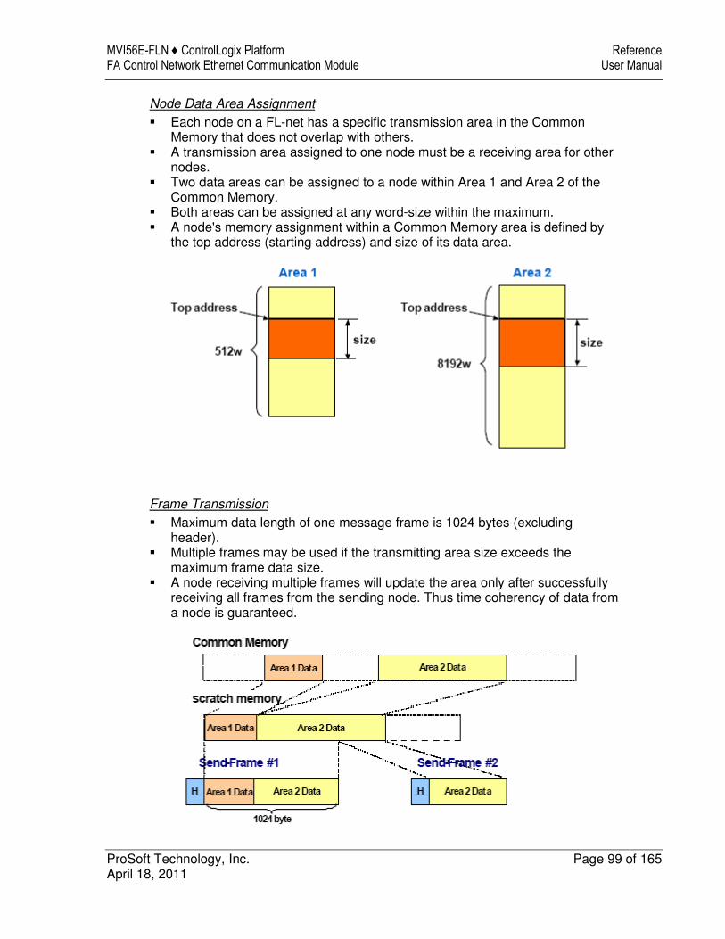
MVI56E-FLN ♦ ControlLogix Platform Reference FA Control Network Ethernet Communication Module User Manual
ProSoft Technology, Inc. Page 99 of 165 April 18, 2011
Node Data Area Assignment
� Each node on a FL-net has a specific transmission area in the Common Memory that does not overlap with others.
� A transmission area assigned to one node must be a receiving area for other nodes.
� Two data areas can be assigned to a node within Area 1 and Area 2 of the Common Memory.
� Both areas can be assigned at any word-size within the maximum. � A node's memory assignment within a Common Memory area is defined by
the top address (starting address) and size of its data area.
Frame Transmission
� Maximum data length of one message frame is 1024 bytes (excluding header).
� Multiple frames may be used if the transmitting area size exceeds the maximum frame data size.
� A node receiving multiple frames will update the area only after successfully receiving all frames from the sending node. Thus time coherency of data from a node is guaranteed.

Reference MVI56E-FLN ♦ ControlLogix Platform User Manual FA Control Network Ethernet Communication Module
Page 100 of 165 ProSoft Technology, Inc. April 18, 2011
Common Memory Function
A node can use the whole Common Memory as receiving area.
Node for Reception Only
Nodes can be set up to only receive data.

MVI56E-FLN ♦ ControlLogix Platform Reference FA Control Network Ethernet Communication Module User Manual
ProSoft Technology, Inc. Page 101 of 165 April 18, 2011
Node Having No Common Memory
The FA link protocol allows for the existence of nodes that do not have Common Memory because they only participate in message transmission, and do not transmit and receive cyclic data.

Reference MVI56E-FLN ♦ ControlLogix Platform User Manual FA Control Network Ethernet Communication Module
Page 102 of 165 ProSoft Technology, Inc. April 18, 2011
User-Defined Specifications
User-defined specifications allow the following range of features that are required for FA systems.
1 Large-scale network
Up to 254 devices (nodes) can be connected in the physical layer of the network. "1 through 254" shall be used as node number. However, numbers "250 through 254" are reserved for maintenance purposes. Number "0" shall not be used. Number "255" shall be used as the global address for broadcasting.
2 Dual communications functions to suit application
The Common Memory function uses cyclic transmission so that each node can always share the same data with other nodes on the network. FL-net also supports message communications for use when handling only essential data is required.
3 Large-capacity Common Memory
The Common Memory is provided with a large capacity of 8K bits (Area 1) and 8K words (Area 2).
4 High-speed response
High-speed response time of 50 milliseconds / 32 nodes (for 2K bits and 2K words) is provided. The absence of a Master in the FL-net network enables nodes to be added or removed readily without affecting any other nodes. This allows any node to be turned ON or OFF easily and facilitates maintenance.
The FL-net protocol is characterized by the following items:
1 Transmission control using masterless token system avoids collision. 2 Refresh cycle time can be specified since the system circulates a token in a
fixed time. 3 The token is transmitted together with cyclic data. 4 The node with a smallest node number among those who participate the
network at start-up time shall start to send the token. 5 If no token is transmitted for a specified period, next node in the token
circulation ring shall send a new token. 6 The masterless token system (characterized by the above two items) will
keep the network from stopping in case of failure of some nodes. 7 The protocol provides information management tables for useful information
to refer operation status of other nodes such as operation mode (RUN / STOP) and hardware malfunction (ALARM).

MVI56E-FLN ♦ ControlLogix Platform Reference FA Control Network Ethernet Communication Module User Manual
ProSoft Technology, Inc. Page 103 of 165 April 18, 2011
4.2.2 Data Flow between Module and Processor
The following discussion outlines the flow of data between the two pieces of hardware (ControlLogix processor and MVI56E-FLN module) and other nodes on the TCP/IP network.
Module’s Cyclic Input Data
Module’s Cyclic Output Data
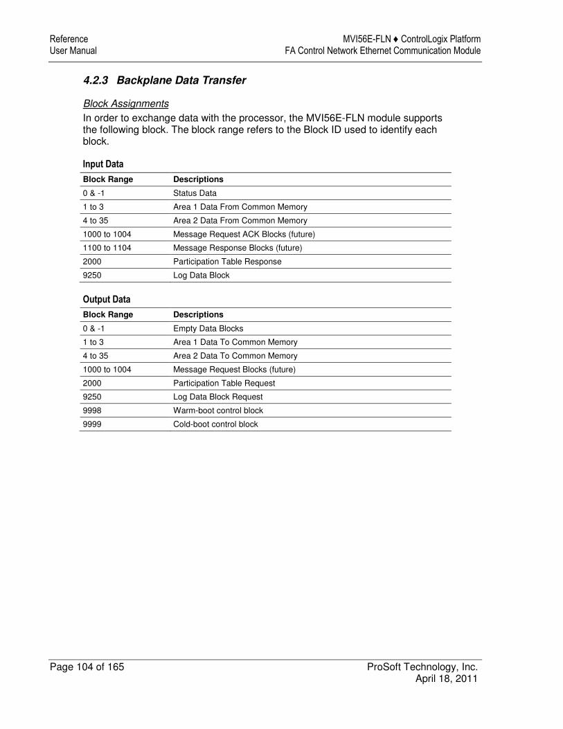
Reference MVI56E-FLN ♦ ControlLogix Platform User Manual FA Control Network Ethernet Communication Module
Page 104 of 165 ProSoft Technology, Inc. April 18, 2011
4.2.3 Backplane Data Transfer
Block Assignments
In order to exchange data with the processor, the MVI56E-FLN module supports the following block. The block range refers to the Block ID used to identify each block.
Input Data
Block Range Descriptions
0 & -1 Status Data
1 to 3 Area 1 Data From Common Memory
4 to 35 Area 2 Data From Common Memory
1000 to 1004 Message Request ACK Blocks (future)
1100 to 1104 Message Response Blocks (future)
2000 Participation Table Response
9250 Log Data Block
Output Data
Block Range Descriptions
0 & -1 Empty Data Blocks
1 to 3 Area 1 Data To Common Memory
4 to 35 Area 2 Data To Common Memory
1000 to 1004 Message Request Blocks (future)
2000 Participation Table Request
9250 Log Data Block Request
9998 Warm-boot control block
9999 Cold-boot control block
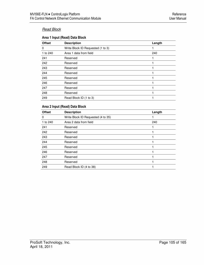
MVI56E-FLN ♦ ControlLogix Platform Reference FA Control Network Ethernet Communication Module User Manual
ProSoft Technology, Inc. Page 105 of 165 April 18, 2011
Read Block
Area 1 Input (Read) Data Block
Offset Description Length
0 Write Block ID Requested (1 to 3) 1
1 to 240 Area 1 data from field 240
241 Reserved 1
242 Reserved 1
243 Reserved 1
244 Reserved 1
245 Reserved 1
246 Reserved 1
247 Reserved 1
248 Reserved 1
249 Read Block ID (1 to 3) 1
Area 2 Input (Read) Data Block
Offset Description Length
0 Write Block ID Requested (4 to 35) 1
1 to 240 Area 2 data from field 240
241 Reserved 1
242 Reserved 1
243 Reserved 1
244 Reserved 1
245 Reserved 1
246 Reserved 1
247 Reserved 1
248 Reserved 1
249 Read Block ID (4 to 38) 1
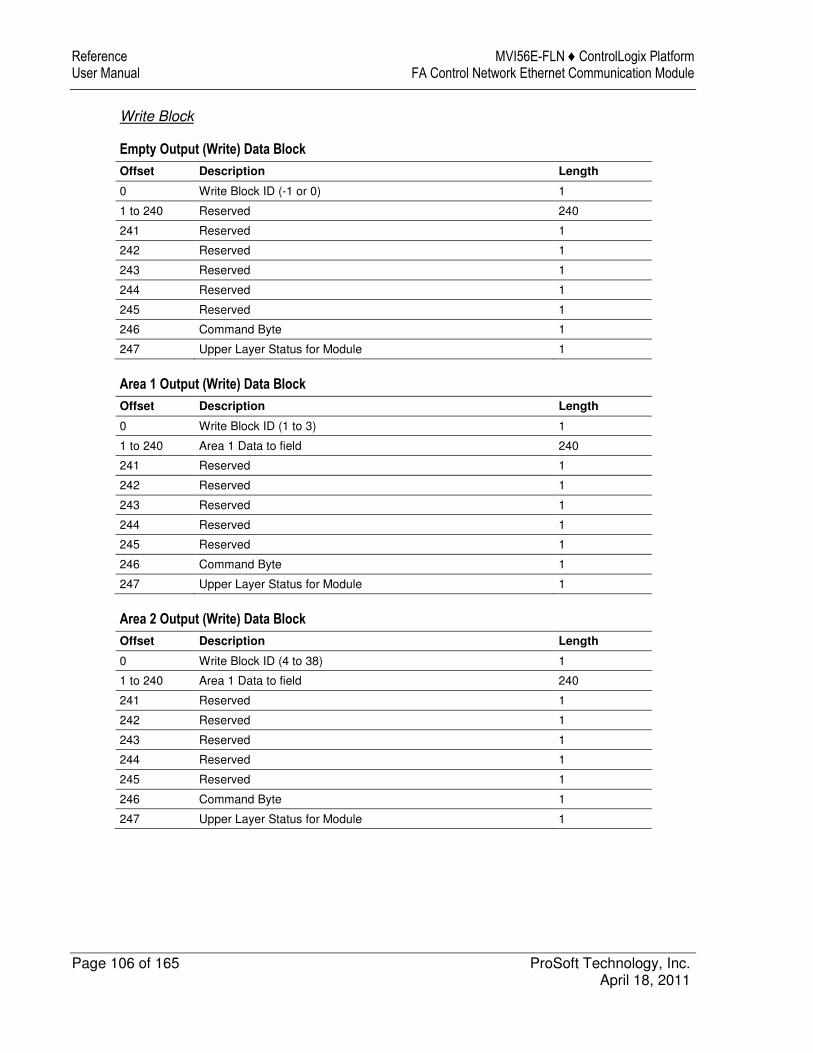
Reference MVI56E-FLN ♦ ControlLogix Platform User Manual FA Control Network Ethernet Communication Module
Page 106 of 165 ProSoft Technology, Inc. April 18, 2011
Write Block
Empty Output (Write) Data Block
Offset Description Length
0 Write Block ID (-1 or 0) 1
1 to 240 Reserved 240
241 Reserved 1
242 Reserved 1
243 Reserved 1
244 Reserved 1
245 Reserved 1
246 Command Byte 1
247 Upper Layer Status for Module 1
Area 1 Output (Write) Data Block
Offset Description Length
0 Write Block ID (1 to 3) 1
1 to 240 Area 1 Data to field 240
241 Reserved 1
242 Reserved 1
243 Reserved 1
244 Reserved 1
245 Reserved 1
246 Command Byte 1
247 Upper Layer Status for Module 1
Area 2 Output (Write) Data Block
Offset Description Length
0 Write Block ID (4 to 38) 1
1 to 240 Area 1 Data to field 240
241 Reserved 1
242 Reserved 1
243 Reserved 1
244 Reserved 1
245 Reserved 1
246 Command Byte 1
247 Upper Layer Status for Module 1
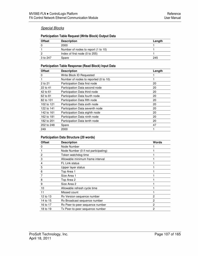
MVI56E-FLN ♦ ControlLogix Platform Reference FA Control Network Ethernet Communication Module User Manual
ProSoft Technology, Inc. Page 107 of 165 April 18, 2011
Special Blocks
Participation Table Request (Write Block) Output Data
Offset Description Length
0 2000 1
1 Number of nodes to report (1 to 10) 1
2 Index of first node (0 to 255) 1
3 to 247 Spare 245
Participation Table Response (Read Block) Input Data
Offset Description Length
0 Write Block ID Requested 1
1 Number of nodes to reported (0 to 10) 1
2 to 21 Participation Data first node 20
22 to 41 Participation Data second node 20
42 to 61 Participation Data third node 20
62 to 81 Participation Data fourth node 20
82 to 101 Participation Data fifth node 20
102 to 121 Participation Data sixth node 20
122 to 141 Participation Data seventh node 20
142 to 161 Participation Data eighth node 20
162 to 181 Participation Data ninth node 20
182 to 201 Participation Data tenth node 20
202 to 248 Spare 47
249 2000 1
Participation Data Structure (20 words)
Offset Description Words
0 Node Number 1
1 Node Number (0 if not participating) 1
2 Token watchdog time 1
3 Allowable minimum frame interval 1
4 FL Link status 1
5 Upper layer status 1
6 Top Area 1 1
7 Size Area 1 1
8 Top Area 2 1
9 Size Area 2 1
10 Allowable refresh cycle time 1
11 Missed count 1
12 to 13 Rx Version sequence number 2
14 to 15 Rx Broadcast sequence number 2
16 to 17 Rx Peer-to-peer sequence number 2
18 to 19 Tx Peer-to-peer sequence number 2

Reference MVI56E-FLN ♦ ControlLogix Platform User Manual FA Control Network Ethernet Communication Module
Page 108 of 165 ProSoft Technology, Inc. April 18, 2011
Log Data Request (Write Block) Output Data
Offset Description Length
0 9250 1
1 to 247 Spare 247
Log Data Request (Read Block) Input Data
Offset Description Length
0 Write Block ID Requested 1
1 Spare 1
2 to 3 Socket Tx count 2
4 to 5 Socket Tx error count 2
6 to 7 Socket Rx count 2
8 to 9 Socket Rx error count 2
10 to 11 Tokens Tx 2
12 to 13 Cyclic Tx 2
14 to 15 Peer-to-peer message Tx 2
16 to 17 Broadcast message Tx 2
18 to 19 Tokens Rx 2
20 to 21 Cyclic Rx 2
22 to 23 Peer-to-peer message Rx 2
24 to 25 Broadcast message Rx 2
26 to 27 Cyclic Rx errors 2
28 to 29 Cyclic Rx address size errors 2
30 to 31 Cyclic Rx CBN errors 2
32 to 33 Cyclic Rx TBN errors 2
34 to 35 Cyclic Rx BSIZE errors 2
36 to 37 Message retrans 2
38 to 39 Message over retrans 2
40 to 41 Message Rx errors 2
42 to 43 Message Rx version sequence errors 2
44 to 45 Message sequence retrans errors 2
46 to 47 ACK errors 2
48 to 49 ACK version sequence errors 2
50 to 51 ACK sequence errors 2
52 to 53 ACK node number errors 2
54 to 55 ACK TCD errors 2
56 to 57 Token multiple errors 2
58 to 59 Token discards 2
60 to 61 Token reissued 2
62 to 63 Token holding timeouts 2
64 to 65 Token monitoring timeouts 2
66 to 67 Total service time (seconds) 2
68 to 69 Frames waiting 2
70 to 71 Number of nodes participating 2
72 to 73 Self exits 2
74 to 75 Exits by skipping 2
76 to 77 Exits of other nodes 2

MVI56E-FLN ♦ ControlLogix Platform Reference FA Control Network Ethernet Communication Module User Manual
ProSoft Technology, Inc. Page 109 of 165 April 18, 2011
Offset Description Length
78 to 79 Spare 2
80 Node holding token 1
81 Network allowable min frame interval 1
82 Network allowable refresh cycle time 1
83 Current measured refresh cycle time 1
84 Maximum refresh cycle time 1
85 Minimum refresh cycle time 1
86 to 248 Spare 163
249 9250 1
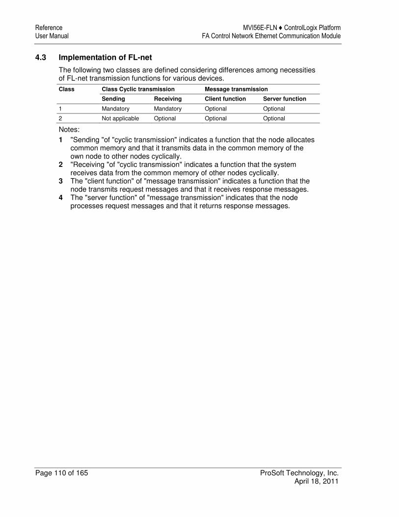
Reference MVI56E-FLN ♦ ControlLogix Platform User Manual FA Control Network Ethernet Communication Module
Page 110 of 165 ProSoft Technology, Inc. April 18, 2011
4.3 Implementation of FL-net
The following two classes are defined considering differences among necessities of FL-net transmission functions for various devices.
Class Class Cyclic transmission Message transmission
Sending Receiving Client function Server function
1 Mandatory Mandatory Optional Optional
2 Not applicable Optional Optional Optional
Notes:
1 "Sending "of "cyclic transmission" indicates a function that the node allocates common memory and that it transmits data in the common memory of the own node to other nodes cyclically.
2 "Receiving "of "cyclic transmission" indicates a function that the system receives data from the common memory of other nodes cyclically.
3 The "client function" of "message transmission" indicates a function that the node transmits request messages and that it receives response messages.
4 The "server function" of "message transmission" indicates that the node processes request messages and that it returns response messages.
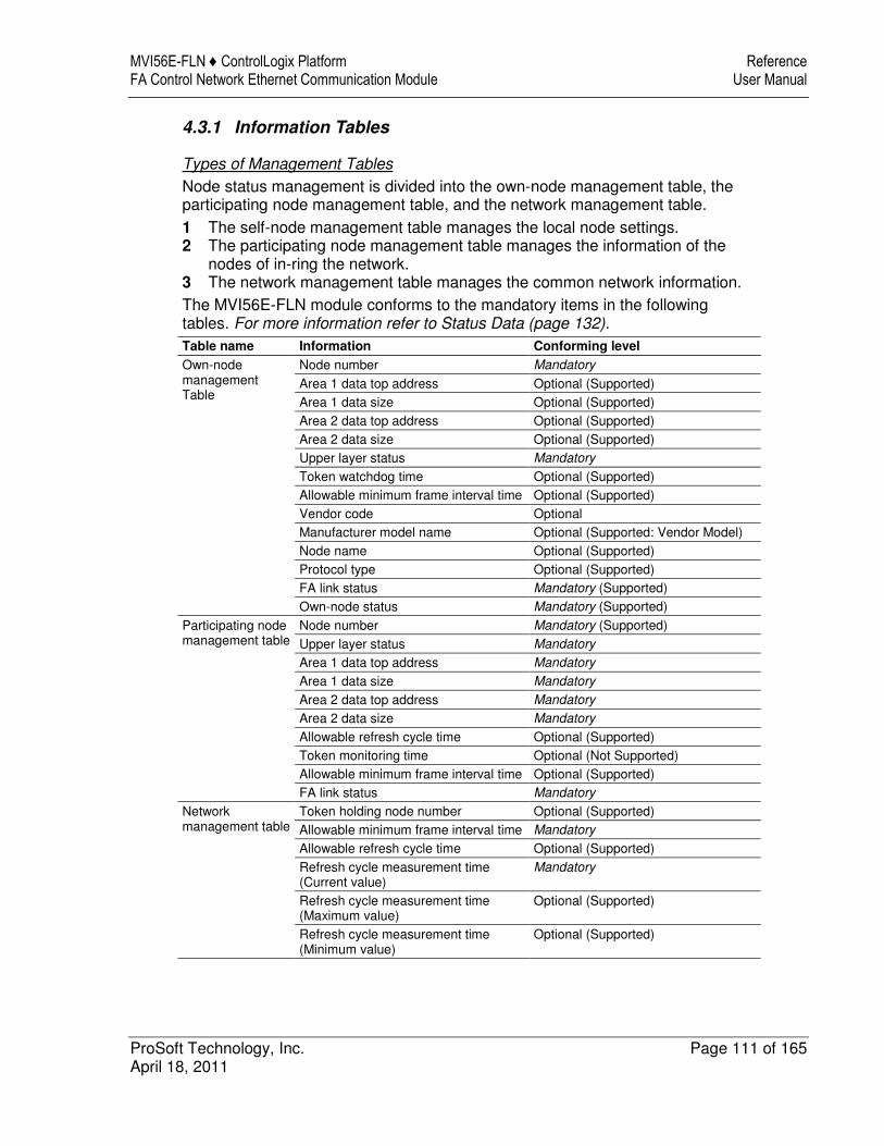
MVI56E-FLN ♦ ControlLogix Platform Reference FA Control Network Ethernet Communication Module User Manual
ProSoft Technology, Inc. Page 111 of 165 April 18, 2011
4.3.1 Information Tables
Types of Management Tables
Node status management is divided into the own-node management table, the participating node management table, and the network management table.
1 The self-node management table manages the local node settings. 2 The participating node management table manages the information of the
nodes of in-ring the network. 3 The network management table manages the common network information.
The MVI56E-FLN module conforms to the mandatory items in the following tables. For more information refer to Status Data (page 132).
Table name Information Conforming level
Own-node management Table
Node number Mandatory
Area 1 data top address Optional (Supported)
Area 1 data size Optional (Supported)
Area 2 data top address Optional (Supported)
Area 2 data size Optional (Supported)
Upper layer status Mandatory
Token watchdog time Optional (Supported)
Allowable minimum frame interval time Optional (Supported)
Vendor code Optional
Manufacturer model name Optional (Supported: Vendor Model)
Node name Optional (Supported)
Protocol type Optional (Supported)
FA link status Mandatory (Supported)
Own-node status Mandatory (Supported)
Participating node management table
Node number Mandatory (Supported)
Upper layer status Mandatory
Area 1 data top address Mandatory
Area 1 data size Mandatory
Area 2 data top address Mandatory
Area 2 data size Mandatory
Allowable refresh cycle time Optional (Supported)
Token monitoring time Optional (Not Supported)
Allowable minimum frame interval time Optional (Supported)
FA link status Mandatory
Network management table
Token holding node number Optional (Supported)
Allowable minimum frame interval time Mandatory
Allowable refresh cycle time Optional (Supported)
Refresh cycle measurement time (Current value)
Mandatory
Refresh cycle measurement time (Maximum value)
Optional (Supported)
Refresh cycle measurement time (Minimum value)
Optional (Supported)

Reference MVI56E-FLN ♦ ControlLogix Platform User Manual FA Control Network Ethernet Communication Module
Page 112 of 165 ProSoft Technology, Inc. April 18, 2011
Own-Node Management Table
This table manages manages the local node settings.
1 The table is used to network parameter read and participation request frames.
2 Management data is set from the FA link protocol upper layer at the node startup time.
3 The node names and the top addresses and size of the transmitting area in the Common Memory can be set from the network.
Table name Size Description
Node number 1 byte 1 to 249 (addresses 0 and 250-255 are special function)
Common Memory Area 1 first word 2 bytes Word address (0 to 1FFH)
Common Memory Area 1 data size 2 bytes Size (0 to 200H)
Common Memory Area 2 first word 2 bytes Word address (0 to 1FFFH)
Common Memory Area 2 data size 2 bytes Size (0 to 2000H)
Upper layer status 2 bytes RUN / STOP / ALARM / WARNING / NORMAL
See status block (page 132) for additional information
Token watchdog time 1 byte 1 to 255 ms
Minimum frame interval time 1 byte 10 to 50 (in units of 100 ms)
Vendor code 10 bytes Vendor code
Manufacturer model 10 bytes Manufacture model, device name
Node name (equipment name) 10 bytes User-defined node name
Protocol version 1 byte 80h (fixed)
FA link status 1 byte In-ring / out-ring, and so on.
Own status 1 byte Duplicate node number detection, and so on.

MVI56E-FLN ♦ ControlLogix Platform Reference FA Control Network Ethernet Communication Module User Manual
ProSoft Technology, Inc. Page 113 of 165 April 18, 2011
Participating Node Management Table
This table manages information on the nodes in the network.
The node status of each node joining in the network is monitored by the management table held by each node. Regarding the nodes joining the network, this table handles the data to be managed for each node.
1 At a start, participating node management table and the network management table is created in accordance with the received token frame.
2 Upon receipt of each token frame, each node updates the participating node management table.
3 Upon receipt of the participation request frame for new joining, the joining node management table is updated.
4 When non-reception of a token frame of each node or a timeout is detected 3 times running, the corresponding node is deleted from the table.
Table name Size Description
Node number 1 byte 1 to 249 if participating (a zero in this field for a node indicates the node is not participating on the network)
Upper layer status 2 bytes RUN / STOP / ALARM / WARNING / NORMAL
See status block for additional information
Common Memory Area 1 data first word 2 bytes Word address (0 to 1FFH)
Common Memory Area 1 data size 2 bytes Size (0 to 200H)
Common Memory Area 2 data first word 2 bytes Word address (0 to 1FFFH)
Common Memory Area 2 data size 2 bytes Size (0 to 2000H)
Allowable refresh cycle time 2 bytes 1 ms. (unit)
Token watchdog time 1 byte 1 to 255 ms
Minimum frame interval time 1 byte 1 to 50 (in units of 100 ms)
FA link status 1 byte In-ring / out-ring information, and so on.
Network Management Table
This table manages information that is shared by all nodes on the network.
Table name Size Description
Token-holding node number 1 byte Node currently holding the token
Minimum frame interval time 1 byte 1 to 50 (in units of 100 ms)
Allowable refresh cycle time 2 bytes 1 ms. (unit)
Refresh cycle measurement time (current) 2 bytes 0 to 65535 ms
Refresh cycle measurement time (maximum) 2 bytes 1 ms. (unit)
Refresh cycle measurement time (minimum) 2 bytes 1 ms. (unit)

Reference MVI56E-FLN ♦ ControlLogix Platform User Manual FA Control Network Ethernet Communication Module
Page 114 of 165 ProSoft Technology, Inc. April 18, 2011
4.3.2 Upper Layer Status Read Definition
The node status is divided into two types: FA link protocol upper layer status (referred to as the upper layer status) and FA link protocol status (referred to as the FA link status).
Upper Layer Status
The upper layer status is divided into upper layer operation information and upper layer error information.
Upper layer operation information
� RUN: Indicates that the upper layer program is running. � STOP: Indicates that the upper layer program is at a stop.
Upper layer error information
� NORMAL: Indicates that the upper layer is normal and both cyclic data and message data are guaranteed.
� WARNING: Indicates that there occurs an error that permits continuing operation in the upper layer but both cyclic data and message data are guaranteed.
� ALARM: Indicates that there occurs an error that does not permit continuing operation in the upper layer and both cyclic data and message data are not guaranteed.
Contents of error in the upper layer: Indicates the contents of an error in the upper layer program.
The upper layer program means those that have an interface with the FA link protocol upper layer, which for the MVI-FLN module is the ControlLogix processor.
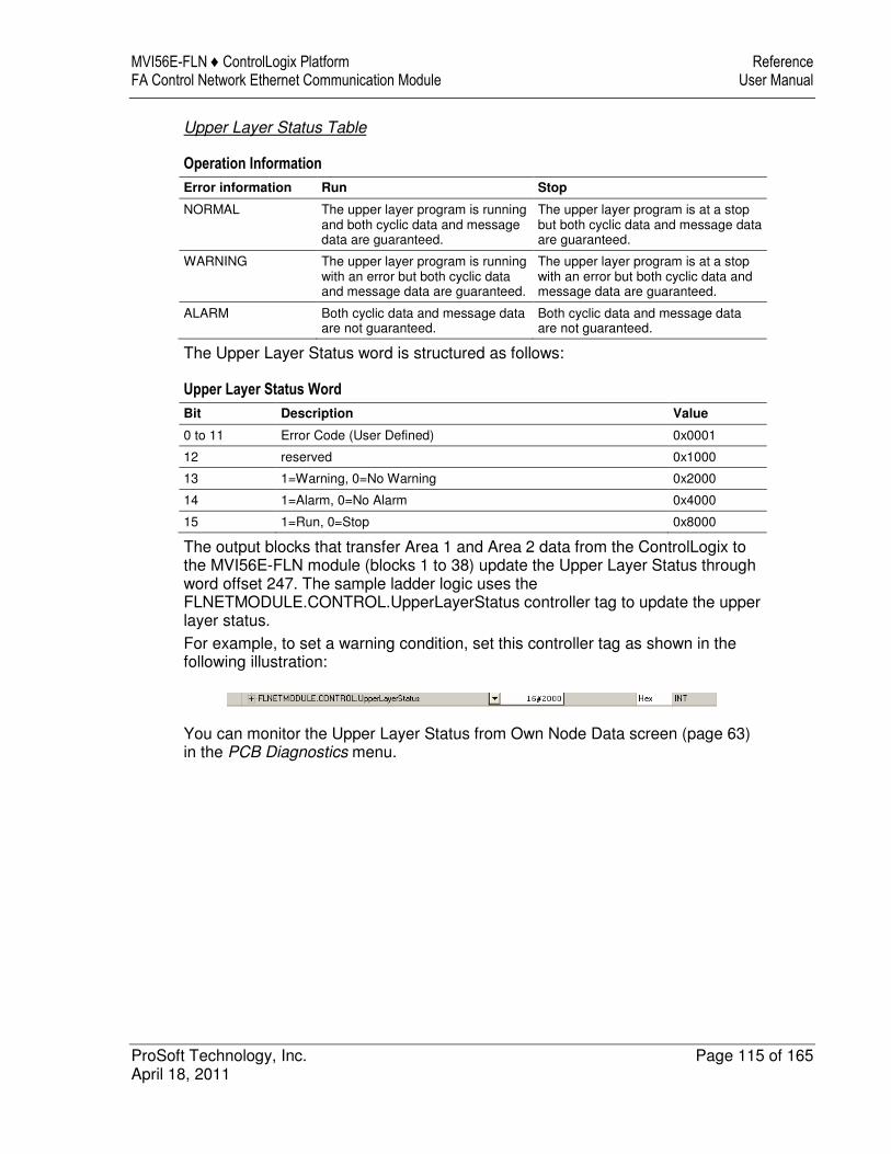
MVI56E-FLN ♦ ControlLogix Platform Reference FA Control Network Ethernet Communication Module User Manual
ProSoft Technology, Inc. Page 115 of 165 April 18, 2011
Upper Layer Status Table
Operation Information
Error information Run Stop
NORMAL The upper layer program is running and both cyclic data and message data are guaranteed.
The upper layer program is at a stop but both cyclic data and message data are guaranteed.
WARNING The upper layer program is running with an error but both cyclic data and message data are guaranteed.
The upper layer program is at a stop with an error but both cyclic data and message data are guaranteed.
ALARM Both cyclic data and message data are not guaranteed.
Both cyclic data and message data are not guaranteed.
The Upper Layer Status word is structured as follows:
Upper Layer Status Word
Bit Description Value
0 to 11 Error Code (User Defined) 0x0001
12 reserved 0x1000
13 1=Warning, 0=No Warning 0x2000
14 1=Alarm, 0=No Alarm 0x4000
15 1=Run, 0=Stop 0x8000
The output blocks that transfer Area 1 and Area 2 data from the ControlLogix to the MVI56E-FLN module (blocks 1 to 38) update the Upper Layer Status through word offset 247. The sample ladder logic uses the FLNETMODULE.CONTROL.UpperLayerStatus controller tag to update the upper layer status.
For example, to set a warning condition, set this controller tag as shown in the following illustration:
You can monitor the Upper Layer Status from Own Node Data screen (page 63) in the PCB Diagnostics menu.
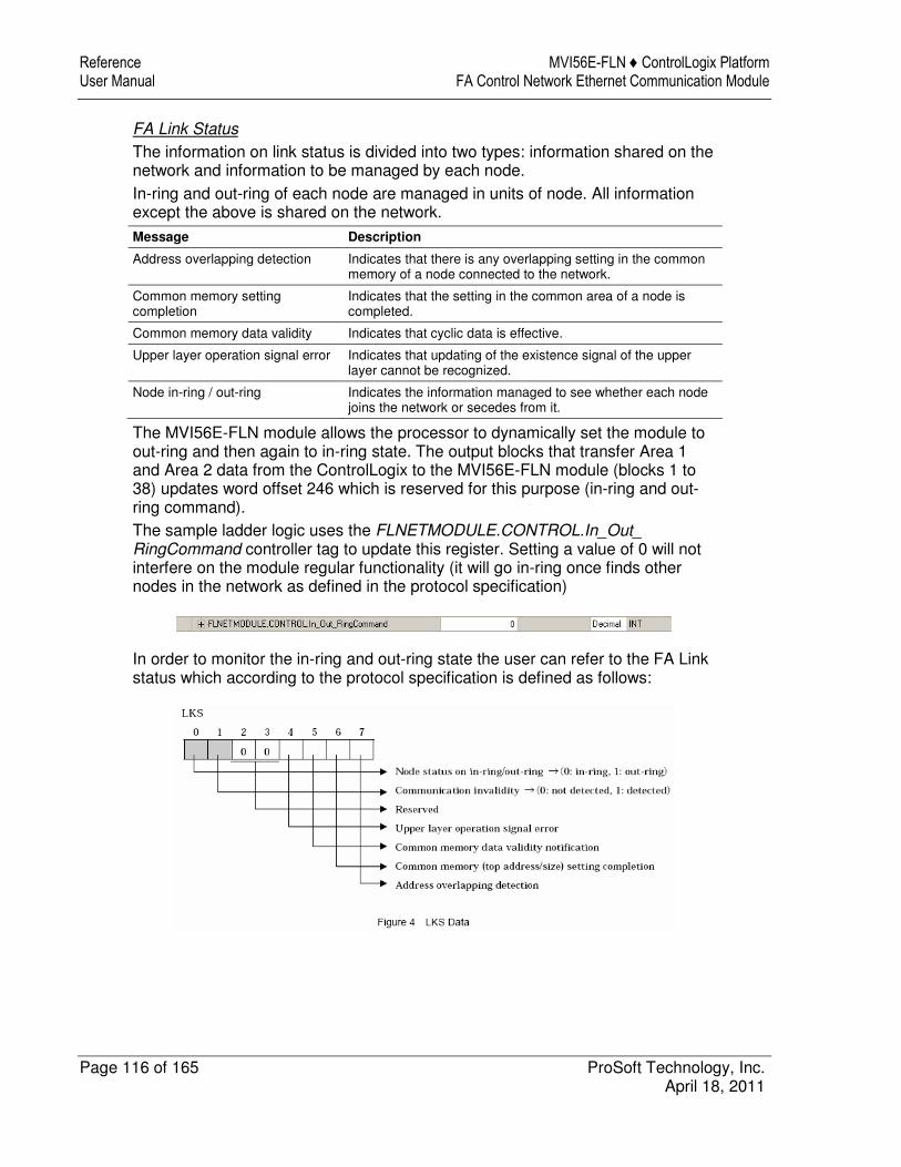
Reference MVI56E-FLN ♦ ControlLogix Platform User Manual FA Control Network Ethernet Communication Module
Page 116 of 165 ProSoft Technology, Inc. April 18, 2011
FA Link Status
The information on link status is divided into two types: information shared on the network and information to be managed by each node.
In-ring and out-ring of each node are managed in units of node. All information except the above is shared on the network.
Message Description
Address overlapping detection Indicates that there is any overlapping setting in the common memory of a node connected to the network.
Common memory setting completion
Indicates that the setting in the common area of a node is completed.
Common memory data validity Indicates that cyclic data is effective.
Upper layer operation signal error Indicates that updating of the existence signal of the upper layer cannot be recognized.
Node in-ring / out-ring Indicates the information managed to see whether each node joins the network or secedes from it.
The MVI56E-FLN module allows the processor to dynamically set the module to out-ring and then again to in-ring state. The output blocks that transfer Area 1 and Area 2 data from the ControlLogix to the MVI56E-FLN module (blocks 1 to 38) updates word offset 246 which is reserved for this purpose (in-ring and out-ring command).
The sample ladder logic uses the FLNETMODULE.CONTROL.In_Out_ RingCommand controller tag to update this register. Setting a value of 0 will not interfere on the module regular functionality (it will go in-ring once finds other nodes in the network as defined in the protocol specification)
In order to monitor the in-ring and out-ring state the user can refer to the FA Link status which according to the protocol specification is defined as follows:
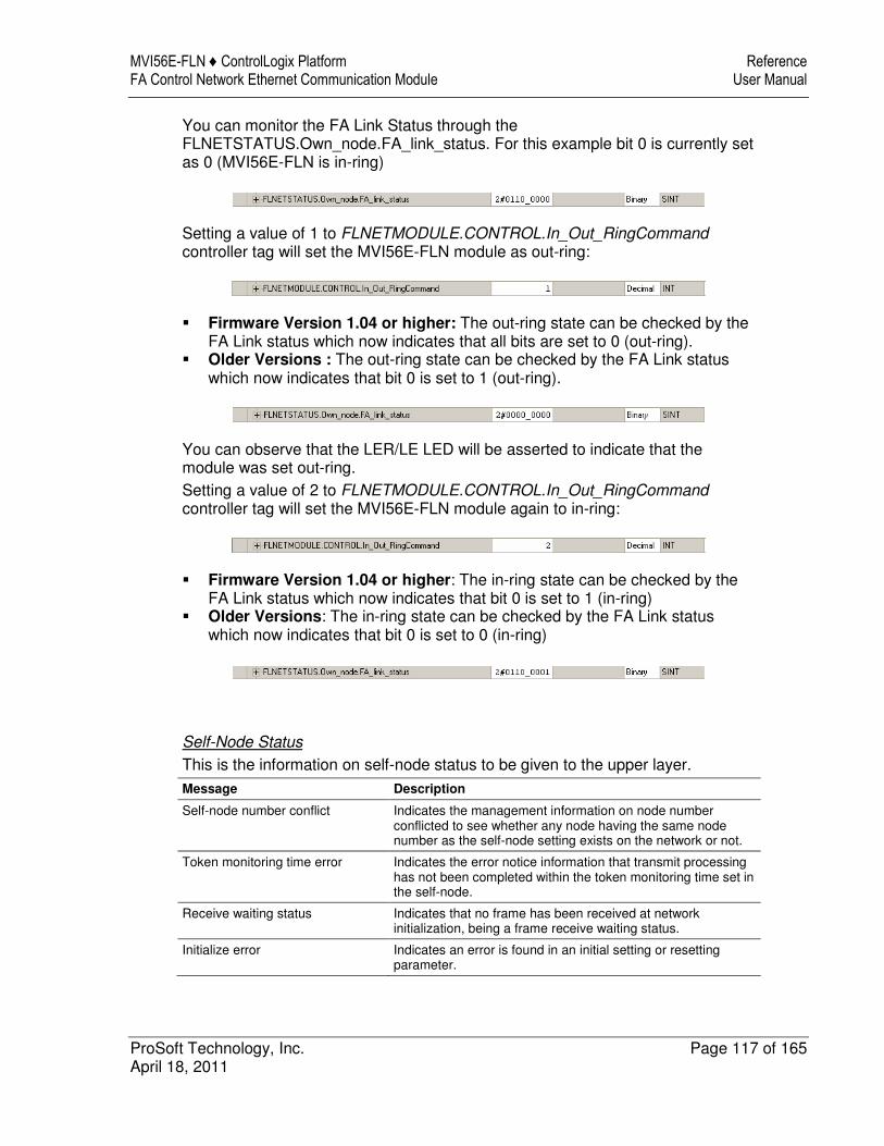
MVI56E-FLN ♦ ControlLogix Platform Reference FA Control Network Ethernet Communication Module User Manual
ProSoft Technology, Inc. Page 117 of 165 April 18, 2011
You can monitor the FA Link Status through the FLNETSTATUS.Own_node.FA_link_status. For this example bit 0 is currently set as 0 (MVI56E-FLN is in-ring)
Setting a value of 1 to FLNETMODULE.CONTROL.In_Out_RingCommand controller tag will set the MVI56E-FLN module as out-ring:
� Firmware Version 1.04 or higher: The out-ring state can be checked by the FA Link status which now indicates that all bits are set to 0 (out-ring).
� Older Versions : The out-ring state can be checked by the FA Link status which now indicates that bit 0 is set to 1 (out-ring).
You can observe that the LER/LE LED will be asserted to indicate that the module was set out-ring.
Setting a value of 2 to FLNETMODULE.CONTROL.In_Out_RingCommand controller tag will set the MVI56E-FLN module again to in-ring:
� Firmware Version 1.04 or higher: The in-ring state can be checked by the FA Link status which now indicates that bit 0 is set to 1 (in-ring)
� Older Versions: The in-ring state can be checked by the FA Link status which now indicates that bit 0 is set to 0 (in-ring)
Self-Node Status
This is the information on self-node status to be given to the upper layer.
Message Description
Self-node number conflict Indicates the management information on node number conflicted to see whether any node having the same node number as the self-node setting exists on the network or not.
Token monitoring time error Indicates the error notice information that transmit processing has not been completed within the token monitoring time set in the self-node.
Receive waiting status Indicates that no frame has been received at network initialization, being a frame receive waiting status.
Initialize error Indicates an error is found in an initial setting or resetting parameter.
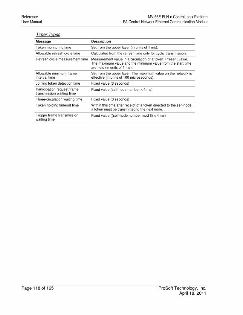
Reference MVI56E-FLN ♦ ControlLogix Platform User Manual FA Control Network Ethernet Communication Module
Page 118 of 165 ProSoft Technology, Inc. April 18, 2011
Timer Types
Message Description
Token monitoring time Set from the upper layer (in units of 1 ms).
Allowable refresh cycle time Calculated from the refresh time only for cyclic transmission.
Refresh cycle measurement time Measurement value in a circulation of a token: Present value. The maximum value and the minimum value from the start time are held (in units of 1 ms).
Allowable minimum frame interval time
Set from the upper layer. The maximum value on the network is effective (in units of 100 microseconds).
Joining token detection time Fixed value (3 seconds)
Participation request frame transmission waiting time
Fixed value (self-node number × 4 ms)
Three-circulation waiting time Fixed value (3 seconds)
Token holding timeout time Within this time after receipt of a token directed to the self-node, a token must be transmitted to the next node.
Trigger frame transmission waiting time
Fixed value ((self-node number mod 8) × 4 ms)

MVI56E-FLN ♦ ControlLogix Platform Reference FA Control Network Ethernet Communication Module User Manual
ProSoft Technology, Inc. Page 119 of 165 April 18, 2011
4.3.3 Lower Layer Protocol
Address Setting
IP Address
The IP address is set from the upper layer of the FA link protocol.
The sub-network mask is also set from the upper layer of the FA link protocol.
The default value of the transmission source is specified as 192.168.250.N (N = node No.: 1 to 125).
The default value of the transmission destination is specified as 192.168.250.255.
Remarks: For the IP address, it is recommended that class C is used and that the lower host address is matched with the FA link protocol node No
MAC Address
As the MAC address, the default set in the unit is used.
Port Number
For reception
� Cyclic transmission port number (for system: 55000 fixed) � Message transmission port number (for system: 55001 fixed) � Participation request frame port number (for system: 55002 fixed)
For transmission
� Transmission port number (for system: 55003 fixed)

Reference MVI56E-FLN ♦ ControlLogix Platform User Manual FA Control Network Ethernet Communication Module
Page 120 of 165 ProSoft Technology, Inc. April 18, 2011
4.4 FL-net Protocol and Network
4.4.1 Understanding the Basics of FL-net
The MVI56E-FLN module is equipped to be used with 10Base-T FL-net (Version 2.00) Systems.
The basic configuration of a 10Base-T FL-net System consists of one hub to which nodes are attached in star form through twisted-pair cable.
4.4.2 Data Frame ID of FL-net
When review the network with an analyzer such as Ethereal the user can examine the protocol frames and use the following table to determine the transaction type.
Data Frame ID: Transaction Code
Transaction Code Application
0 to 59999 Transparent mode message frame
60000 to 64999 Reserved
65000 Cyclic frame (with token)
65001 Cyclic frame (without token)
65002 Participation request frame
65003 Byte block read frame (request)
65004 Byte block write frame (request)
65005 Word block read frame (request)
65006 Word block write frame (request)
65007 Network parameter read frame (request)
65008 Network parameter write frame (request)
65009 Stop command frame (request)
65010 Start command frame (request)
65011 Profile read frame (request)
65012 Trigger frame
65013 Log data read frame (request)
65014 Log data clear frame (request)
65015 Echo back message frame (request)
65016 to 65202 Reserved (for future expansion)
65203 Byte block read frame (response)
65204 Byte block write frame (response)
65205 Word block read frame (response)
65206 Word block write frame (response)
65207 Network parameter read frame (response)
65208 Network parameter write frame (response)
65209 Stop command frame (response)
65210 Start command (response)
65211 Profile read frame (response)
65212 Reserved
65213 Log data read frame (response)
65214 Log data clear frame (response)
65215 Echo back message frame (response)

MVI56E-FLN ♦ ControlLogix Platform Reference FA Control Network Ethernet Communication Module User Manual
ProSoft Technology, Inc. Page 121 of 165 April 18, 2011
Transaction Code Application
65216 to 65399 Reserved (for future expansion)
65400 to 65535 Reserved
4.4.3 Allowable Refresh Cycle Time
Each node always monitors the message frames in the network in the period from receipt of a token until receipt of the next token to the node. If there is no message frame in the network in this 1 cycle, this cycle time × 1.2 is specified as the allowable refresh cycle time.
When the network is started, the allowable refresh cycle time is set to "0". When a token directed to the node is received 3 times at the start-up, a refresh cycle measurement will be started. Accordingly, the network does not perform message transmission before a token is circulated once.
A node that joins in the halfway participation status, starts measuring the refresh cycle time after the third token reception to the node.
The allowable refresh cycle time is dynamically determined depending on the number of nodes joining the network.
4.4.4 Memory Resources
The module provides 8700 words for shared Area 1 and Area 2 Common Memory.

Reference MVI56E-FLN ♦ ControlLogix Platform User Manual FA Control Network Ethernet Communication Module
Page 122 of 165 ProSoft Technology, Inc. April 18, 2011
4.4.5 Message Transmissions
� A token-holding node can send up to one message frame. � 1:1 transmission and 1:N transmission are provided. � Message acknowledges is available for 1:1 transmission.
Type of message ACK response Re-send Sequence No. control
1:1 message transmission Yes Yes Yes
1:N message transmission No No Yes

MVI56E-FLN ♦ ControlLogix Platform Reference FA Control Network Ethernet Communication Module User Manual
ProSoft Technology, Inc. Page 123 of 165 April 18, 2011
Message Transmission Services
Type of Message Service Remarks
Read byte block data Not supported
Write byte block data Not supported
Read word block data Not supported
Write word block data Not supported
Read network parameter Supported
Write network parameter Not supported
Start operation Not supported
Stop operation Not supported
Read profile Supported
Read log data Supported
Clear log data Supported
Transparent mode message Not Supported
Echo back message Supported

Reference MVI56E-FLN ♦ ControlLogix Platform User Manual FA Control Network Ethernet Communication Module
Page 124 of 165 ProSoft Technology, Inc. April 18, 2011
4.4.6 Message Transmission Function
Message transmission is a function that supports non-cyclic data exchange between nodes. The MVI56E-FLN module does not support the optional messaging functions except in response to Log Data request messages as follow:
Log data read: Function reads the log data on a specified node.
� (Request) No data division. � (Normal response) 512 bytes � (Error response) The data division includes an error code.
Log data clear: Function clears the log related to a specified node.
� (Request) No data division. � (Normal response) No data division. � (Error response) The data division includes an error code.
Items provided for "Log Data Read" service
Major items Minor items Implemented (Y) or not(N)
Transmission / reception
Total number of transmission at socket unit * Y
Total number of transmission errors at socket unit * Y
Number of Ethernet transmission errors N
Total number of receptions * Y
Total number of reception errors * Y
Frame types
Number of Ethernet reception errors N
Number of tokens transmitted Y
Number of cyclic frames transmitted Y
Number of peer-to-peer messages transmissions Y
Number of broadcast messages transmissions Y
Number of tokens received Y
Cyclic transmission
Number of cyclic frames received Y
Number of peer-to-peer messages received Y
Number of broadcast messages received Y
Number of cyclic reception errors * Y
Number of cyclic address size errors Y
Number of cyclic CBN errors Y
Message transmission
Number of cyclic TBN errors Y
Number of cyclic BSIZE errors Y
Number of message retransmissions * Y
Number of message over-retransmissions * Y
Number of message reception errors * Y
Number of message version-of-sequence number errors Y
Number of message sequence number retransmissions recognized
Y
ACK-related Number of ACK errors * Y
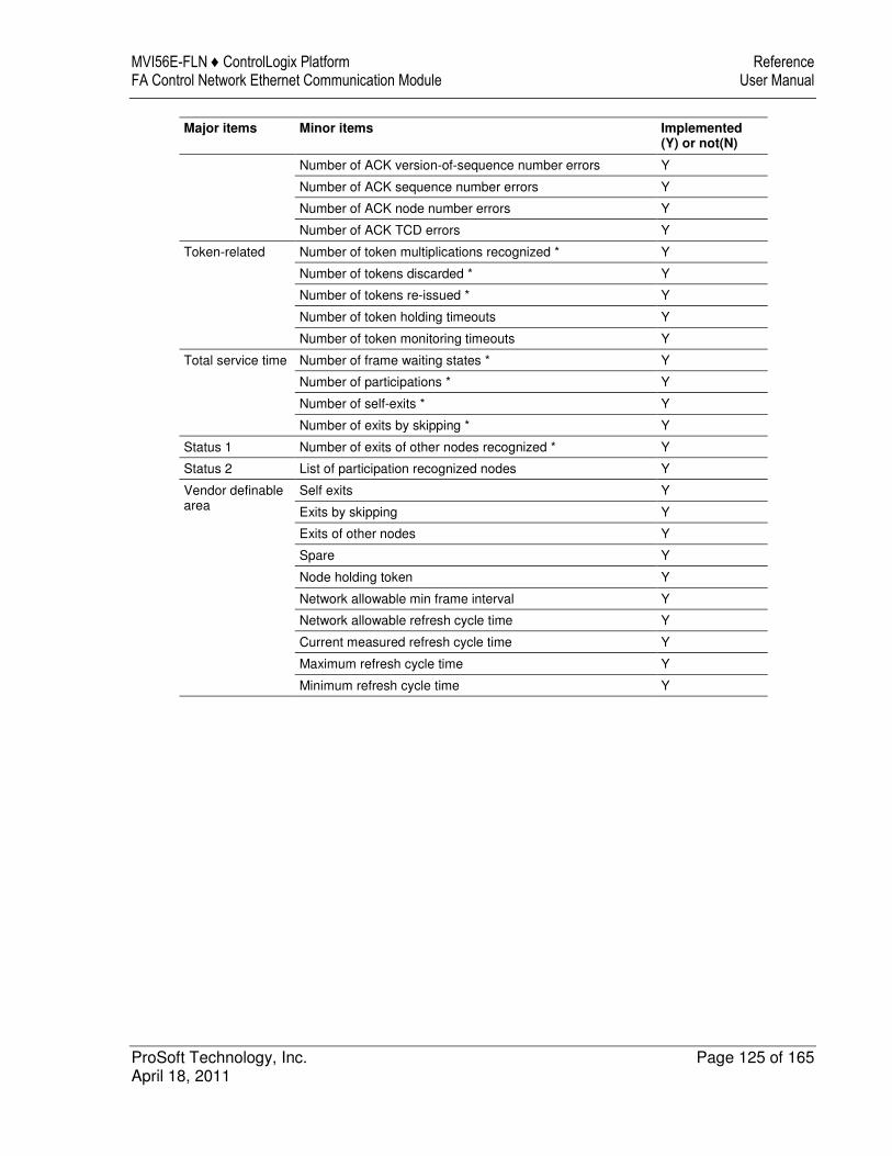
MVI56E-FLN ♦ ControlLogix Platform Reference FA Control Network Ethernet Communication Module User Manual
ProSoft Technology, Inc. Page 125 of 165 April 18, 2011
Major items Minor items Implemented (Y) or not(N)
Number of ACK version-of-sequence number errors Y
Number of ACK sequence number errors Y
Number of ACK node number errors Y
Number of ACK TCD errors Y
Token-related
Number of token multiplications recognized * Y
Number of tokens discarded * Y
Number of tokens re-issued * Y
Number of token holding timeouts Y
Number of token monitoring timeouts Y
Total service time
Number of frame waiting states * Y
Number of participations * Y
Number of self-exits * Y
Number of exits by skipping * Y
Status 1 Number of exits of other nodes recognized * Y
Status 2 List of participation recognized nodes Y
Vendor definable area
Self exits Y
Exits by skipping Y
Exits of other nodes Y
Spare Y
Node holding token Y
Network allowable min frame interval Y
Network allowable refresh cycle time Y
Current measured refresh cycle time Y
Maximum refresh cycle time Y
Minimum refresh cycle time Y

Reference MVI56E-FLN ♦ ControlLogix Platform User Manual FA Control Network Ethernet Communication Module
Page 126 of 165 ProSoft Technology, Inc. April 18, 2011
4.4.7 Data Volume and Number of Frames
The frame structure for cyclic transmission depends on the data volume consisting of Area 1 and Area 2.
1 When the data volume is 1024 bytes or less: This data is transmitted by one frame.
Figure when the transit data volume is 1024 bytes or less
2 When the data volume exceeds 1024 bytes: This data is transmitted by 2 frames of more in divided form.
Figure when the transmit data volume exceeds 1024 bytes
Two or more divided frames are continuously sent in the token held state.

MVI56E-FLN ♦ ControlLogix Platform Reference FA Control Network Ethernet Communication Module User Manual
ProSoft Technology, Inc. Page 127 of 165 April 18, 2011
4.4.8 Network Management
� Nodes can be added while the FL-net system is running. � The system will continue to run even if any node fails. � Each node knows the state of all the other nodes.
Each node manages In-ring and Out-ring of nodes
� One token is circulated between all nodes in the FL-net and the token is monitored by the time of each node. If a node does not send the token, the next node will reissue it after a fixed time interval.
� Out-ring management
If a node does not send the token, every node will recognize the node failure.
� In-ring management
New node sends a participation request frame and every node monitors it.
� Node state management
Network status and upper layer status are attached in the cyclic frame.
4.4.9 Masterless Transmission Management
Token
1 A node can transmit data only while holding a token, with the following two exceptions:
� Reissue of token due to failure of a node to send a token within the token monitoring time
� Transmission of participation request frame when the node has not joined in the network
1 A single token is circulated among nodes. A node receiving a token holds the transmission right until it releases the token to the next node.
2 The token is circulated between all the nodes joining the FL-net. 3 The token can be transmitted along with cyclic data. 4 The token can also be circulated without any data. 5 The token is monitored by each node's timer. If the token is not released by a
node within a fixed time, the token is automatically reissued. 6 If there are two tokens in the network, they are combined into one.

Reference MVI56E-FLN ♦ ControlLogix Platform User Manual FA Control Network Ethernet Communication Module
Page 128 of 165 ProSoft Technology, Inc. April 18, 2011
Token Flow
Only one token exists in the network.
A frame including a token (token frame) is provided with a destination node number and node number of token transmitting side. Each node becomes a token holding node when a match is found with the destination node number of the received token frame.
The token rotation order is determined in the ascending order of node number. The node with the largest node number releases a token to the node with the smallest node number.
Token and Frames
There are six types of frames sent with a token.
1 When there is no cyclic data to be sent, only a token is transmitted. 2 When there is only cyclic data, a token is transmitted together with cyclic
data. 3 When there is only cyclic data and this cyclic data is sent in divided form, only
the cyclic frames are transmitted and a token is attached to the last cyclic frame.
4 When there is only message data, the message frame is transmitted, followed by a token.
5 When there is cyclic data and message data, the message frame is transmitted and then the cyclic frame is transmitted together with a token.

MVI56E-FLN ♦ ControlLogix Platform Reference FA Control Network Ethernet Communication Module User Manual
ProSoft Technology, Inc. Page 129 of 165 April 18, 2011
6 When there is cyclic data and message data and the cyclic data is sent in divided form: The message frame is transmitted and then only the cyclic frames are transmitted and a token is attached to the last frame.

Reference MVI56E-FLN ♦ ControlLogix Platform User Manual FA Control Network Ethernet Communication Module
Page 130 of 165 ProSoft Technology, Inc. April 18, 2011
4.4.10 FA Link Protocol
In-Ring and Out-Ring Management
In-ring and out-ring of other nodes
At network initialization, each node monitors the line until the joining token detection time is up. If the node monitors token flow, the node considers it as a halfway participation state and performs the processing of (1) below. In the other case, if the node does not monitor any token, the node considers itself as a network start-up state and performs the processing of (2) below.
1 When monitoring a token flow (halfway participation state)
When monitoring a token flow within the joining token detection time, it is recognized that a link is already established. At this time, the node waits for transmission of a participation request frame until the token is circulated 3 times. In this period, a node number conflict check and an address overlapping check of common memory are made by the received frames and the participating node management table is updated. If any address overlapping is detected, the node set the common memory top address and data size of areas 1 and 2 to 0 and shall not transmit cyclic data. At the same time, the node sets the address overlapping flag, and resets the common memory data validity flag. When no error is found in node number, the node will send out a participation request frame after the participation request frame transmission waiting time is up. The participation request frame is transmitted regardless of token holding. A node that has recognized a node number conflict does not transmit a participation request frame and does not join the network. The node number conflict error shall be notified to the upper layer. When a token for the self-node is not received after the third circulation though the node joined the network by the participation request frame, this node transmits a participation request frame again. Token monitoring is performed for the joining token detection time. When a token is received, the node is put into a halfway participation status. When no token is received, it is put into a network startup status that will be described later.
2 When receiving no token (network startup status)
When no token is monitored during the joining token detection time, the node transmits a trigger frame after the remainder of (node number / 8) x 4 milliseconds. If a trigger frame is received before the node transmits its trigger frame, the node shall transmit no trigger frame. When the participation request frame transmission waiting time (node number x 4 milliseconds) is up after a first trigger frame reception, each node transmits its participation request frame. During the participation request frame reception waiting time (1200 milliseconds) after a first trigger frame reception, a conflict check of node number and an address overlapping check are made and the participating node management table is updated, thus each node shall wait for all nodes to transmit participation request frames.

MVI56E-FLN ♦ ControlLogix Platform Reference FA Control Network Ethernet Communication Module User Manual
ProSoft Technology, Inc. Page 131 of 165 April 18, 2011
A node that recognized address overlapping by the participation request frame reception from other nodes sets the common memory top address and common memory size of areas 1 and 2 to 0 and does not transmit cyclic data. At the same time, the node set the address overlapping and reset the common memory data validity flag. The node having the smallest node number transmits a token first according to the participating node management table after the participation request frame reception waiting time is up. A node that recognized conflict of node number does not transmit and receive data at all. A joining error in the network shall be notified to the upper layer. A conflict of node number / address overlapping check are made when the node does not yet join the network. At the initial startup status, a conflict of node number / address overlapping check are made for both nodes that transmitted a participation request frame and nodes that did not transmit it. If overlapping is detected, the corresponding processing is performed. When a node does not receive even one frame during the participation request frame reception waiting time, the node executes the start up sequence from monitoring the token for the joining token detection time. If the existence of other nodes is not recognized in the period from transmission of the third participation request frame until the participation request frame reception waiting time is up, the node sets a frame waiting flag. The node continues to resend a participation request frame until the network is established. In case other nodes have fallen off and only one node remains during token circulation with the result that the node waits for a trigger frame or a token frame, the above is also applicable.

Reference MVI56E-FLN ♦ ControlLogix Platform User Manual FA Control Network Ethernet Communication Module
Page 132 of 165 ProSoft Technology, Inc. April 18, 2011
4.5 Error and Status Data
4.5.1 Status Data
Status Input (Read) Data Block
Offset Description Length
0 Write Block ID Requested (0 &-1) 1
1 FA_link status & Own status 1
2 Number of Nodes Active 1
3 to 18 Participation List 16
19 to 34 Nodes With Active Data 16
35 Token Node & MFT 1
36 Allowable refresh cycle time 1
37 Current refresh cycle time 1
38 Maximum refresh cycle time 1
39 Minimum refresh cycle time 1
40 Frames waiting to send 1
41 Node Number & protocol 1
42 FL-Status & Own Status 1
43 Top Area 1 1
44 Size Area 1 1
45 Top Area 2 1
46 Size Area 2 1
47 Upper Layer Status 1
48 Watchdog Timeout & MFT 1
49 to 53 Vendor Code (10 bytes) 5
54 to 58 Vendor Model (10 bytes) 5
59 to 63 Node Name (10 bytes) 5
64 Network Token Node & MFT 1
65 Network Allowable refresh cycle time 1
66 Network current refresh cycle time 1
67 Network maximum refresh cycle time 1
68 Network minimum refresh cycle time 1
69 to 99 Reserved for future use 31
100 Program scan counter 1
101 to 102 Product Code 2
103 to 104 Revision 2
105 to 106 Operating system revision 2
107 to 108 Run number 2
109 Block read count 1
110 Block write count 1
111 Block parse count 1
112 Block error count 1
113 to 248 Reserved for future use 136
249 Read Block ID (-1 or 0) 1

MVI56E-FLN ♦ ControlLogix Platform Reference FA Control Network Ethernet Communication Module User Manual
ProSoft Technology, Inc. Page 133 of 165 April 18, 2011
4.6 FL-net Device Profile for MVI56E-FLN Module
4.6.1 Text Notation of Profile
Name of Parameter Characters used [Printable String type], (length), (characters)
Data type [Type] Text Notation (Length), (content)
Version of device profile common specification
6, "COMVER" INTEGER 1, 1
System parameter ID 2, "ID" Printable String 7, "SYSPARA"
System parameter revision number
3, "REV" INTEGER 1, 0
System parameter revision date
7, "REVDATE" [INTEGER], 2, (0001 to 9999),
[INTEGER], 1, (01 to 12),
[INTEGER], 1, (01 to 31)
2, 2006
1, 5
1, 30
Device type 10, "DVCATEGORY" Printable String 5, "OTHER"
Vendor name 6, "VENDOR" Printable String 24, "PROSOFT TECHNOLOGY, INC."
Product name 7, "DVMODEL" Printable String 9, "MVI56E-FLN"
Abstract Syntax of Profile
1) Type Definition
OtherRecord: :=
SEQUENCE
{
syspara SysparaType
}
SysparaType: :=
SEQUENCE
{
nameCOMVER NameType
paraCOMVER INTEGER
nameID NameType
paraID NameType
nameREV NameType
paraREV INTEGER
nameREVDATE NameType
paraREVDATE DateType
nameDVCATEGORY NameType
paraDVCATEGORY NameType
nameVENDOR NameType
paraVENDOR NameType
nameDVMODEL NameType
paraDVMODEL NameType
}

Reference MVI56E-FLN ♦ ControlLogix Platform User Manual FA Control Network Ethernet Communication Module
Page 134 of 165 ProSoft Technology, Inc. April 18, 2011
2) Value Definition
{
syspara
{
nameCOMVER "COMVER",
paraCOMVER 1,
nameID "ID",
paraID "SYSPARA",
nameREV "REV",
paraREV 0,
nameREVDATE "REVDATE",
paraREVDATE {
year 2006,
month 5,
day 30
},
nameDVCATEGORY "DVCATEGORY",
paraDVCATEGORY "OTHER",
nameVENDOR "VENDOR",
paraVENDOR "PROSOFT TECHNOLOGY, INC.",
nameDVMODEL "DVMODEL",
paraDVMODEL "MVI56E-FLN"
}
}

MVI56E-FLN ♦ ControlLogix Platform Reference FA Control Network Ethernet Communication Module User Manual
ProSoft Technology, Inc. Page 135 of 165 April 18, 2011
MVI56E-FLN Transfer Syntax Data Array (Coding)
Identifier Length
30 8180 Identifier Length
30 7E Identifier Length Content
13 06 "COMVER"
02 01 1
13 02 "ID"
13 07 "SYSPARA"
13 03 "REV"
02 01 0
13 07 "REVDATE"
Identifier Length Content
30 0A Identifier Length Content
02 02 07D6
02 01 05
02 01 1E
Identifier Length Content
13 0A "DVCATEGORY"
13 05 "OTHER"
13 06 "VENDOR"
13 18 "PROSOFT TECHNOLOGY, INC."
13 07 "DVMODEL"
13 09 "MVI56E-FLN"
MVI56E-FLN Profile Data Array
Relative Address
0 1 2 3 4 5 6 7 8 9 A B C D E F
00 30 81 80 30 7E 13 06 "C" "O" "M" "V" "E" "R" 02 01 1
10 13 02 "I" "D" 13 07 "S" "Y" "S" "P" "A" "R" "A" 13 03 "R"
20 "E" "V" 02 01 00 13 07 "R" "E" "V" "D" "A" "T" "E" 30 0A
30 02 02 07 D6 02 01 05 02 01 1E 13 0A "D" "V" "C" "A"
40 "T" "E" "G" "O" "R" "Y" 13 05 "O" "T" "H" "E" "R" 13 06 "V"
50 "E" "N" "D" "O" "R" 13 18 "P" "R" "O" "S" "O" "F" "T" " " "T"
60 "E" "C" "H" "N" "O" "L" "O" "G" "Y" "," " " "I" "N" "C" "." 13
70 07 "D" "V" "M" "O" "D" "E" "L" 13 09 "M" "V" "I" "5" "6" "-"
80 "F" "L" "N"

Reference MVI56E-FLN ♦ ControlLogix Platform User Manual FA Control Network Ethernet Communication Module
Page 136 of 165 ProSoft Technology, Inc. April 18, 2011
4.7 Module Power Up
4.7.1 Main Logic Loop
4.8 State Transition Diagram
This chapter describes the state transition.
4.8.1 A. State Definitions
1 Initialization monitoring state: Waits for an initialization request from the upper layer and judges if the network link is established
2 Network initialization state: Link establishment state from a link non-establishment state.
3 Halfway joining initialization state: Up to the time when the self-node joins the network in the link establishment state.
4 Token waiting state: State where a token is not held in the link joining state.
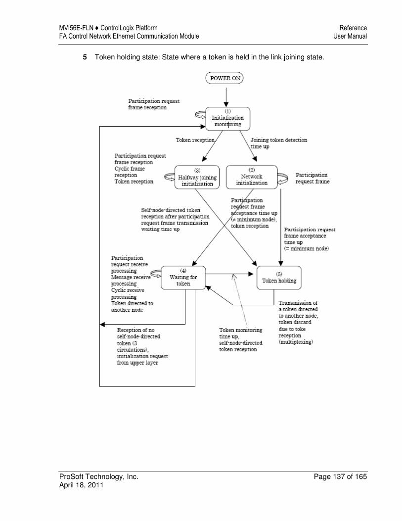
MVI56E-FLN ♦ ControlLogix Platform Reference FA Control Network Ethernet Communication Module User Manual
ProSoft Technology, Inc. Page 137 of 165 April 18, 2011
5 Token holding state: State where a token is held in the link joining state.
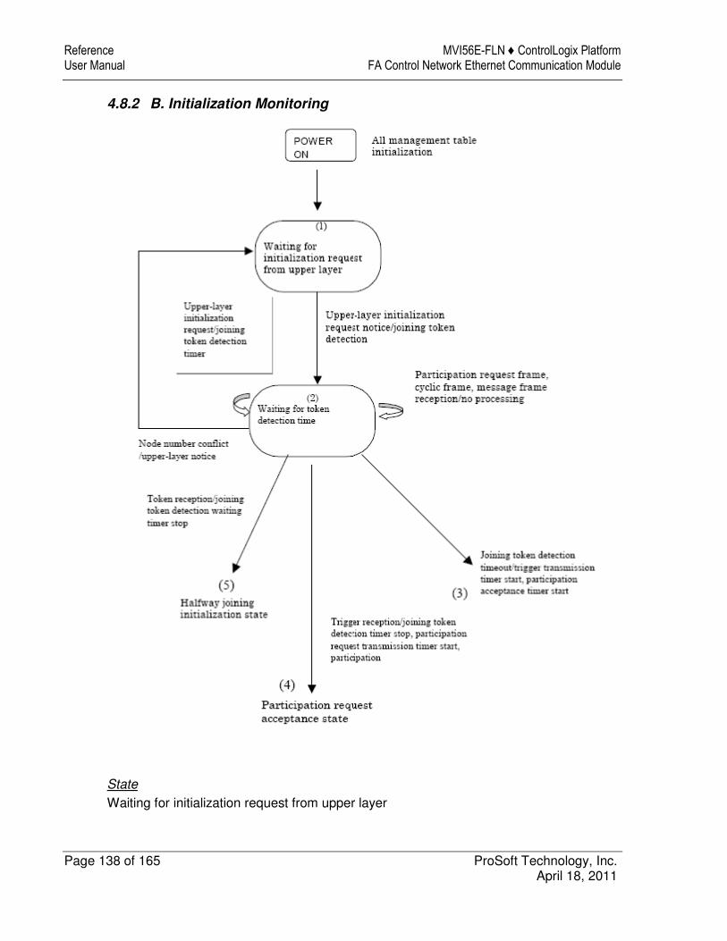
Reference MVI56E-FLN ♦ ControlLogix Platform User Manual FA Control Network Ethernet Communication Module
Page 138 of 165 ProSoft Technology, Inc. April 18, 2011
4.8.2 B. Initialization Monitoring
State
Waiting for initialization request from upper layer

MVI56E-FLN ♦ ControlLogix Platform Reference FA Control Network Ethernet Communication Module User Manual
ProSoft Technology, Inc. Page 139 of 165 April 18, 2011
Because necessary information for joining the network such as self-node No. is not set, a joining operation cannot be started.
The node waits until the parameters that permit joining the network are set by the upper layer.
Waiting for joining token detection timeout Time for judging the current network status. The time starts after an initialization request from the upper layer is accepted. The monitoring time shall be 3 sec.
If even a token is received within this monitoring time, the network is judged as an operating status. When the network is in the operating status, the self-node in the network is put into the halfway joining initialization state.
When the network is not in the operating status, the self-node will join the network at network initialization.
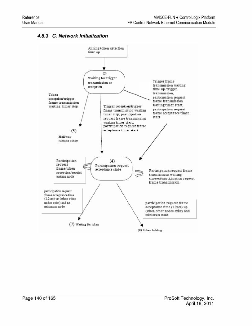
Reference MVI56E-FLN ♦ ControlLogix Platform User Manual FA Control Network Ethernet Communication Module
Page 140 of 165 ProSoft Technology, Inc. April 18, 2011
4.8.3 C. Network Initialization

MVI56E-FLN ♦ ControlLogix Platform Reference FA Control Network Ethernet Communication Module User Manual
ProSoft Technology, Inc. Page 141 of 165 April 18, 2011
4.8.4 D. Halfway Joining Initialization

Reference MVI56E-FLN ♦ ControlLogix Platform User Manual FA Control Network Ethernet Communication Module
Page 142 of 165 ProSoft Technology, Inc. April 18, 2011
4.8.5 E. Waiting for Token

MVI56E-FLN ♦ ControlLogix Platform Reference FA Control Network Ethernet Communication Module User Manual
ProSoft Technology, Inc. Page 143 of 165 April 18, 2011
4.8.6 F. Token Holding
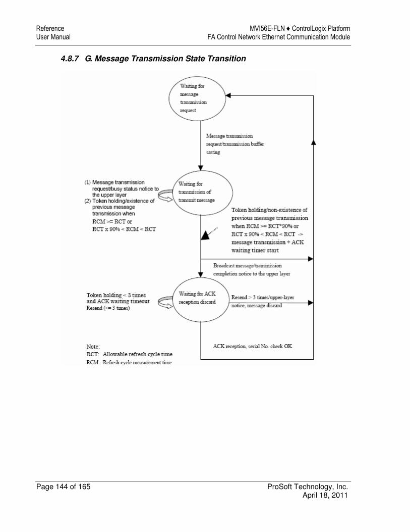
Reference MVI56E-FLN ♦ ControlLogix Platform User Manual FA Control Network Ethernet Communication Module
Page 144 of 165 ProSoft Technology, Inc. April 18, 2011
4.8.7 G. Message Transmission State Transition

MVI56E-FLN ♦ ControlLogix Platform Reference FA Control Network Ethernet Communication Module User Manual
ProSoft Technology, Inc. Page 145 of 165 April 18, 2011
4.8.8 H. Message Reception State Transition

Reference MVI56E-FLN ♦ ControlLogix Platform User Manual FA Control Network Ethernet Communication Module
Page 146 of 165 ProSoft Technology, Inc. April 18, 2011
4.9 Cable Connections - MVI56E-FLN
The MVI56E-FLN module has the following functional communication connections installed:
� One 10/100 Mbps Ethernet port (RJ45 connector, labeled E1) for configuration and troubleshooting only
� One 10/100 Mbps Ethernet port (RJ45 connector, labeled E2) for FL-net application data transfer only
4.9.1 Ethernet Connection
The MVI56E-FLN module has two RJ45 ports located on the front of the module labeled "E1", to be used only for configuration and troubleshooting, and "E2", to be used only for connection to the FL-net FA Control Network.
Warning: The MVI56E-FLN module is NOT compatible with Power Over Ethernet (IEEE802.3af / IEEE802.3at) networks. Do NOT connect the module to Ethernet devices, hubs, switches or networks that supply AC or DC power over the Ethernet cable. Failure to observe this precaution may result in damage to hardware or injury to personnel. Important: The module requires a static (fixed) IP address that is not shared with any other device on the Ethernet network. Obtain a list of suitable IP addresses from your network administrator BEFORE configuring the Ethernet port on this module. The last digit of the IP address for port E2 is the FL-net node number of the module on the FA Control network.
4.9.2 Ethernet Cable Specifications
The recommended cable is Category 5 or better. A Category 5 cable has four twisted pairs of wires, which are color-coded and cannot be swapped. The module uses only two of the four pairs.
The Ethernet ports on the module are Auto-Sensing. You can use either a standard Ethernet straight-through cable or a crossover cable when connecting the module to an Ethernet hub, a 10/100 Base-T Ethernet switch, or directly to a PC. The module will detect the cable type and use the appropriate pins to send and receive Ethernet signals.
Ethernet cabling is like U.S. telephone cables, except that it has eight conductors. Some hubs have one input that can accept either a straight-through or crossover cable, depending on a switch position. In this case, you must ensure that the switch position and cable type agree.
Refer to Ethernet cable configuration (page 147) for a diagram of how to configure Ethernet cable.

MVI56E-FLN ♦ ControlLogix Platform Reference FA Control Network Ethernet Communication Module User Manual
ProSoft Technology, Inc. Page 147 of 165 April 18, 2011
Ethernet Cable Configuration
Note: The standard connector view shown is color-coded for a straight-through cable.
Crossover cable Straight- through cable
RJ-45 PIN RJ-45 PIN
1 Rx+ 3 Tx+
2 Rx- 6 Tx-
3 Tx+ 1 Rx+
6 Tx- 2 Rx-
RJ-45 PIN RJ-45 PIN
1 Rx+ 1 Tx+
2 Rx- 2 Tx-
3 Tx+ 3 Rx+
6 Tx- 6 Rx-

Reference MVI56E-FLN ♦ ControlLogix Platform User Manual FA Control Network Ethernet Communication Module
Page 148 of 165 ProSoft Technology, Inc. April 18, 2011

MVI56E-FLN ♦ ControlLogix Platform Support, Service & Warranty FA Control Network Ethernet Communication Module User Manual
ProSoft Technology, Inc. Page 149 of 165 April 18, 2011
5 Support, Service & Warranty
In This Chapter
� Contacting Technical Support ............................................................. 149
� Return Material Authorization (RMA) Policies and Conditions ............. 151
� LIMITED WARRANTY ......................................................................... 153
Contacting Technical Support
ProSoft Technology, Inc. (ProSoft) is committed to providing the most efficient and effective support possible. Before calling, please gather the following information to assist in expediting this process:
1 Product Version Number 2 System architecture 3 Network details
If the issue is hardware related, we will also need information regarding:
1 Module configuration and associated ladder files, if any 2 Module operation and any unusual behavior 3 Configuration/Debug status information 4 LED patterns 5 Details about the serial, Ethernet or fieldbus devices interfaced to the module,
if any.
Note: For technical support calls within the United States, ProSoft’s 24/7 after-hours phone support is available for urgent plant-down issues. Detailed contact information for all our worldwide locations is available on the following page.

Guide to the MVI56E-FLN User Manual MVI56E-FLN ♦ ControlLogix Platform User Manual FA Control Network Ethernet Communication Module
Page 150 of 165 ProSoft Technology, Inc. April 18, 2011
Internet Web Site: www.prosoft-technology.com/support
E-mail address: [email protected]
Asia Pacific
(location in Malaysia)
Tel: +603.7724.2080, E-mail: [email protected]
Languages spoken include: Chinese, English
Asia Pacific
(location in China)
Tel: +86.21.5187.7337 x888, E-mail: [email protected]
Languages spoken include: Chinese, English
Europe
(location in Toulouse, France)
Tel: +33 (0) 5.34.36.87.20,
E-mail: [email protected]
Languages spoken include: French, English
Europe
(location in Dubai, UAE)
Tel: +971-4-214-6911,
E-mail: [email protected]
Languages spoken include: English, Hindi
North America
(location in California)
Tel: +1.661.716.5100,
E-mail: [email protected]
Languages spoken include: English, Spanish
Latin America
(Oficina Regional)
Tel: +1-281-2989109,
E-Mail: [email protected]
Languages spoken include: Spanish, English
Latin America
(location in Puebla, Mexico)
Tel: +52-222-3-99-6565,
E-mail: [email protected]
Languages spoken include: Spanish
Brasil
(location in Sao Paulo)
Tel: +55-11-5083-3776,
E-mail: [email protected]
Languages spoken include: Portuguese, English
For complete details regarding ProSoft Technology’s TERMS & CONDITIONS OF SALE, WARRANTY, SUPPORT, SERVICE AND RETURN MATERIAL AUTHORIZATION INSTRUCTIONS please see the documents on the Product DVD or go to www.prosoft-technology/legal

MVI56E-FLN ♦ ControlLogix Platform Guide to the MVI56E-FLN User Manual FA Control Network Ethernet Communication Module User Manual
ProSoft Technology, Inc. Page 151 of 165 April 18, 2011
5.1 Return Material Authorization (RMA) Policies and Conditions
The following Return Material Authorization (RMA) Policies and Conditions (collectively, "RMA Policies") apply to any returned product. These RMA Policies are subject to change by ProSoft Technology, Inc., without notice. For warranty information, see Limited Warranty (page 153). In the event of any inconsistency between the RMA Policies and the Warranty, the Warranty shall govern.
5.1.1 Returning Any Product
a) In order to return a Product for repair, exchange, or otherwise, theCustomer must obtain a Return Material Authorization (RMA) numberfrom ProSoft Technology and comply with ProSoft Technology shippinginstructions.
b) In the event that the Customer experiences a problem with the Product forany reason, Customer should contact ProSoft Technical Support at one ofthe telephone numbers listed above (page 149). A Technical SupportEngineer will request that you perform several tests in an attempt toisolate the problem. If after completing these tests, the Product is found tobe the source of the problem, we will issue an RMA.
c) All returned Products must be shipped freight prepaid, in the originalshipping container or equivalent, to the location specified by ProSoftTechnology, and be accompanied by proof of purchase and receipt date.The RMA number is to be prominently marked on the outside of theshipping box. Customer agrees to insure the Product or assume the riskof loss or damage in transit. Products shipped to ProSoft Technologyusing a shipment method other than that specified by ProSoft Technology,or shipped without an RMA number will be returned to the Customer,freight collect. Contact ProSoft Technical Support for further information.
d) A 10% restocking fee applies to all warranty credit returns, whereby aCustomer has an application change, ordered too many, does not need,etc. Returns for credit require that all accessory parts included in theoriginal box (i.e.; antennas, cables) be returned. Failure to return theseitems will result in a deduction from the total credit due for each missingitem.
Guide to the MVI56E-FLN User Manual MVI56E-FLN ♦ ControlLogix Platform User Manual FA Control Network Ethernet Communication Module
Page 152 of 165 ProSoft Technology, Inc. April 18, 2011
5.1.2 Returning Units Under Warranty
A Technical Support Engineer must approve the return of Product under ProSoft Technology’s Warranty:
a) A replacement module will be shipped and invoiced. A purchase order will be required.
b) Credit for a product under warranty will be issued upon receipt of authorized product by ProSoft Technology at designated location referenced on the Return Material Authorization
i. If a defect is found and is determined to be customer generated, or if the defect is otherwise not covered by ProSoft Technology s warranty, there will be no credit given. Customer will be contacted and can request module be returned at their expense;
ii. If defect is customer generated and is repairable, customer can authorize ProSoft Technology to repair the unit by providing a purchase order for 30% of the current list price plus freight charges, duties and taxes as applicable.
5.1.3 Returning Units Out of Warranty
a) Customer sends unit in for evaluation to location specified by ProSoft Technology, freight prepaid.
b) If no defect is found, Customer will be charged the equivalent of $100 USD, plus freight charges, duties and taxes as applicable. A new purchase order will be required.
c) If unit is repaired, charge to Customer will be 30% of current list price (USD) plus freight charges, duties and taxes as applicable. A new purchase order will be required or authorization to use the purchase order submitted for evaluation fee.
The following is a list of non-repairable units:
o 3150 - All o 3750 o 3600 - All o 3700 o 3170 - All o 3250 o 1560 - Can be repaired, only if defect is the power supply o 1550 - Can be repaired, only if defect is the power supply o 3350 o 3300 o 1500 - All

MVI56E-FLN ♦ ControlLogix Platform Guide to the MVI56E-FLN User Manual FA Control Network Ethernet Communication Module User Manual
ProSoft Technology, Inc. Page 153 of 165 April 18, 2011
5.2 LIMITED WARRANTY
This Limited Warranty ("Warranty") governs all sales of hardware, software, and other products (collectively, "Product") manufactured and/or offered for sale by ProSoft Technology, Incorporated (ProSoft), and all related services provided by ProSoft, including maintenance, repair, warranty exchange, and service programs (collectively, "Services"). By purchasing or using the Product or Services, the individual or entity purchasing or using the Product or Services ("Customer") agrees to all of the terms and provisions (collectively, the "Terms") of this Limited Warranty. All sales of software or other intellectual property are, in addition, subject to any license agreement accompanying such software or other intellectual property.
5.2.1 What Is Covered By This Warranty
a) Warranty On New Products: ProSoft warrants, to the original purchaser, that the Product that is the subject of the sale will (1) conform to and perform in accordance with published specifications prepared, approved and issued by ProSoft, and (2) will be free from defects in material or workmanship; provided these warranties only cover Product that is sold as new. This Warranty expires three (3) years from the date of shipment for Product purchased on or after January 1st, 2008, or one (1) year from the date of shipment for Product purchased before January 1st, 2008 (the "Warranty Period"). If the Customer discovers within the Warranty Period a failure of the Product to conform to specifications, or a defect in material or workmanship of the Product, the Customer must promptly notify ProSoft by fax, email or telephone. In no event may that notification be received by ProSoft later than 39 months from date of original shipment. Within a reasonable time after notification, ProSoft will correct any failure of the Product to conform to specifications or any defect in material or workmanship of the Product, with either new or remanufactured replacement parts. ProSoft reserves the right, and at its sole discretion, may replace unrepairable units with new or remanufactured equipment. All replacement units will be covered under warranty for the 3 year period commencing from the date of original equipment purchase, not the date of shipment of the replacement unit. Such repair, including both parts and labor, will be performed at ProSoft’s expense. All warranty service will be performed at service centers designated by ProSoft.
b) Warranty On Services: Materials and labor performed by ProSoft to repair a verified malfunction or defect are warranteed in the terms specified above for new Product, provided said warranty will be for the period remaining on the original new equipment warranty or, if the original warranty is no longer in effect, for a period of 90 days from the date of repair.
Guide to the MVI56E-FLN User Manual MVI56E-FLN ♦ ControlLogix Platform User Manual FA Control Network Ethernet Communication Module
Page 154 of 165 ProSoft Technology, Inc. April 18, 2011
5.2.2 What Is Not Covered By This Warranty
a) ProSoft makes no representation or warranty, expressed or implied, that the operation of software purchased from ProSoft will be uninterrupted or error free or that the functions contained in the software will meet or satisfy the purchaser’s intended use or requirements; the Customer assumes complete responsibility for decisions made or actions taken based on information obtained using ProSoft software.
b) This Warranty does not cover the failure of the Product to perform specified functions, or any other non-conformance, defects, losses or damages caused by or attributable to any of the following: (i) shipping; (ii) improper installation or other failure of Customer to adhere to ProSoft’s specifications or instructions; (iii) unauthorized repair or maintenance; (iv) attachments, equipment, options, parts, software, or user-created programming (including, but not limited to, programs developed with any IEC 61131-3, "C" or any variant of "C" programming languages) not furnished by ProSoft; (v) use of the Product for purposes other than those for which it was designed; (vi) any other abuse, misapplication, neglect or misuse by the Customer; (vii) accident, improper testing or causes external to the Product such as, but not limited to, exposure to extremes of temperature or humidity, power failure or power surges; or (viii) disasters such as fire, flood, earthquake, wind and lightning.
c) The information in this Agreement is subject to change without notice. ProSoft shall not be liable for technical or editorial errors or omissions made herein; nor for incidental or consequential damages resulting from the furnishing, performance or use of this material. The user guide included with your original product purchase from ProSoft contains information protected by copyright. No part of the guide may be duplicated or reproduced in any form without prior written consent from ProSoft.
5.2.3 Disclaimer Regarding High Risk Activities
Product manufactured or supplied by ProSoft is not fault tolerant and is not designed, manufactured or intended for use in hazardous environments requiring fail-safe performance including and without limitation: the operation of nuclear facilities, aircraft navigation of communication systems, air traffic control, direct life support machines or weapons systems in which the failure of the product could lead directly or indirectly to death, personal injury or severe physical or environmental damage (collectively, "high risk activities"). ProSoft specifically disclaims any express or implied warranty of fitness for high risk activities.
MVI56E-FLN ♦ ControlLogix Platform Guide to the MVI56E-FLN User Manual FA Control Network Ethernet Communication Module User Manual
ProSoft Technology, Inc. Page 155 of 165 April 18, 2011
5.2.4 Intellectual Property Indemnity
Buyer shall indemnify and hold harmless ProSoft and its employees from and against all liabilities, losses, claims, costs and expenses (including attorney’s fees and expenses) related to any claim, investigation, litigation or proceeding (whether or not ProSoft is a party) which arises or is alleged to arise from Buyer’s acts or omissions under these Terms or in any way with respect to the Products. Without limiting the foregoing, Buyer (at its own expense) shall indemnify and hold harmless ProSoft and defend or settle any action brought against such Companies to the extent based on a claim that any Product made to Buyer specifications infringed intellectual property rights of another party. ProSoft makes no warranty that the product is or will be delivered free of any person’s claiming of patent, trademark, or similar infringement. The Buyer assumes all risks (including the risk of suit) that the product or any use of the product will infringe existing or subsequently issued patents, trademarks, or copyrights.
a) Any documentation included with Product purchased from ProSoft is protected by copyright and may not be duplicated or reproduced in any form without prior written consent from ProSoft.
b) ProSoft’s technical specifications and documentation that are included with the Product are subject to editing and modification without notice.
c) Transfer of title shall not operate to convey to Customer any right to make, or have made, any Product supplied by ProSoft.
d) Customer is granted no right or license to use any software or other intellectual property in any manner or for any purpose not expressly permitted by any license agreement accompanying such software or other intellectual property.
e) Customer agrees that it shall not, and shall not authorize others to, copy software provided by ProSoft (except as expressly permitted in any license agreement accompanying such software); transfer software to a third party separately from the Product; modify, alter, translate, decode, decompile, disassemble, reverse-engineer or otherwise attempt to derive the source code of the software or create derivative works based on the software; export the software or underlying technology in contravention of applicable US and international export laws and regulations; or use the software other than as authorized in connection with use of Product.
f) Additional Restrictions Relating To Software And Other Intellectual Property
In addition to compliance with the Terms of this Warranty, Customers purchasing software or other intellectual property shall comply with any license agreement accompanying such software or other intellectual property. Failure to do so may void this Warranty with respect to such software and/or other intellectual property.
5.2.5 Disclaimer of all Other Warranties
The Warranty set forth in What Is Covered By This Warranty (page 153) are in lieu of all other warranties, express or implied, including but not limited to the implied warranties of merchantability and fitness for a particular purpose.
Guide to the MVI56E-FLN User Manual MVI56E-FLN ♦ ControlLogix Platform User Manual FA Control Network Ethernet Communication Module
Page 156 of 165 ProSoft Technology, Inc. April 18, 2011
5.2.6 Limitation of Remedies **
In no event will ProSoft or its Dealer be liable for any special, incidental or consequential damages based on breach of warranty, breach of contract, negligence, strict tort or any other legal theory. Damages that ProSoft or its Dealer will not be responsible for include, but are not limited to: Loss of profits; loss of savings or revenue; loss of use of the product or any associated equipment; loss of data; cost of capital; cost of any substitute equipment, facilities, or services; downtime; the claims of third parties including, customers of the Purchaser; and, injury to property.
** Some areas do not allow time limitations on an implied warranty, or allow the exclusion or limitation of incidental or consequential damages. In such areas, the above limitations may not apply. This Warranty gives you specific legal rights, and you may also have other rights which vary from place to place.
5.2.7 Time Limit for Bringing Suit
Any action for breach of warranty must be commenced within 39 months following shipment of the Product.
5.2.8 No Other Warranties
Unless modified in writing and signed by both parties, this Warranty is understood to be the complete and exclusive agreement between the parties, suspending all oral or written prior agreements and all other communications between the parties relating to the subject matter of this Warranty, including statements made by salesperson. No employee of ProSoft or any other party is authorized to make any warranty in addition to those made in this Warranty. The Customer is warned, therefore, to check this Warranty carefully to see that it correctly reflects those terms that are important to the Customer.
5.2.9 Allocation of Risks
This Warranty allocates the risk of product failure between ProSoft and the Customer. This allocation is recognized by both parties and is reflected in the price of the goods. The Customer acknowledges that it has read this Warranty, understands it, and is bound by its Terms.

MVI56E-FLN ♦ ControlLogix Platform Guide to the MVI56E-FLN User Manual FA Control Network Ethernet Communication Module User Manual
ProSoft Technology, Inc. Page 157 of 165 April 18, 2011
5.2.10 Controlling Law and Severability
This Warranty shall be governed by and construed in accordance with the laws of the United States and the domestic laws of the State of California, without reference to its conflicts of law provisions. If for any reason a court of competent jurisdiction finds any provisions of this Warranty, or a portion thereof, to be unenforceable, that provision shall be enforced to the maximum extent permissible and the remainder of this Warranty shall remain in full force and effect. Any cause of action with respect to the Product or Services must be instituted in a court of competent jurisdiction in the State of California.

Guide to the MVI56E-FLN User Manual MVI56E-FLN ♦ ControlLogix Platform User Manual FA Control Network Ethernet Communication Module
Page 158 of 165 ProSoft Technology, Inc. April 18, 2011

MVI56E-FLN ♦ ControlLogix Platform Glossary of Terms FA Control Network Ethernet Communication Module User Manual
ProSoft Technology, Inc. Page 159 of 165 April 18, 2011
Glossary of Terms
A
ACK
At communication by message transmission, the data receiving side notifies the transmitting side that the data has been received. This is used only for 1:1 message transmission.
Allowable minimum frame interval
This is the minimum value of frame interval that allows a node to receive a frame.
Allowable refresh cycle time
This time is used for a node to judge whether message transmission should be performed or not.
B
Bit area
This means a 1K-byte area in the common memory.
C
Common memory
A function that permits using a memory in common between nodes under cyclic transmission is provided.
Cyclic transmission
This function supports cyclic data exchange that occurs between nodes.
E
Ethernet
The physical layer and data link layer of the FA link protocol are specified.
F
FA network
This is an abbreviation of the FA control network.

Glossary of Terms MVI56E-FLN ♦ ControlLogix Platform User Manual FA Control Network Ethernet Communication Module
Page 160 of 165 ProSoft Technology, Inc. April 18, 2011
J
Joining token detection time
This is the time to judge whether the network is in operation or not when joining the network. If a token is detected within this time, the network is regarded as being in operation.
M
Message transmission
This function supports non-cyclic data exchange that occurs between nodes.
N
Network management table
This table manages the common parameters on the network.
P
Participating node management table
This table manages the status of each node participating in the network.
R
Resend function
If ACK is not sent back from the receiving side at 1:1 message transmission, this function permits the transmitting side to resend a message.
S
Self-node management table
This table manages the information on the self-node.
Sequence number
This number is used to identify a message as a unique one at message transmission.
T
Token monitoring time
This means the timeout period in which each node holds a token.
MVI56E-FLN ♦ ControlLogix Platform Glossary of Terms FA Control Network Ethernet Communication Module User Manual
ProSoft Technology, Inc. Page 161 of 165 April 18, 2011
V
Version number
This number is used for message transmission. The version number is initialized by random number when a node is started.
W
Word area
This means a 16K-byte area in the common memory.

Glossary of Terms MVI56E-FLN ♦ ControlLogix Platform User Manual FA Control Network Ethernet Communication Module
Page 162 of 165 ProSoft Technology, Inc. April 18, 2011

MVI56E-FLN ♦ ControlLogix Platform Index FA Control Network Ethernet Communication Module User Manual
ProSoft Technology, Inc. Page 163 of 165 April 18, 2011
Index
A
A. State Definitions • 136 About FL-net Protocol • 95 Abstract Syntax of Profile • 133 ACK • 159 Adding the Module to an Existing Project • 31 Address Setting • 119 Allocation of Risks • 156 Allowable minimum frame interval • 159 Allowable refresh cycle time • 159 Allowable Refresh Cycle Time • 121 Area 1 and Area 2 • 98 Area Parameters • 41
B
B. Initialization Monitoring • 138 Backplane Data Transfer • 104 Battery Life Advisory • 4 Bit area • 159 Block Assignments • 104
C
C. Network Initialization • 140 Cable Connections - MVI56E-FLN • 146 Checking Status through ControlLogix Controller Tags
• 65 Checking the Backplane status • 73 Checking the General Network Status • 73 Checking the Log Data • 61, 71 Checking the Network Status • 62 Checking the Nodes Exchanging Data • 59, 66 Checking the Own Node Data • 63, 115 Checking the Own Node Status • 65 Checking the Participating Node Status • 64, 68 Checking the Participating Nodes • 60 Checking the Participation Table • 67 Clearing a Fault Condition • 88 Common memory • 159 Common Memory • 98 Common Memory Function • 100 Configuring Area 1 and Area 2 • 41 Configuring Module Parameters • 38 Configuring the FL-net Device • 48 Configuring the MVI56E-FLN Module • 37 Configuring the RSLinx Driver for the PC COM Port •
29 Connecting the MVI56E-FLN Module to the FL/ET-T-
V2 • 54 Connecting to the Module's Web Page • 25 Connecting Your PC to the ControlLogix Processor •
34
Connecting Your PC to the Module • 19 Contacting Technical Support • 149, 151 Controlling Law and Severability • 157 Creating Optional Comment Entries • 39 Cyclic transmission • 159 Cyclic Transmission • 97
D
D. Halfway Joining Initialization • 141 Data Communication Between Nodes • 96 Data Flow between Module and Processor • 103 Data Frame ID of FL-net • 120 Data Volume and Number of Frames • 126 Determining the Firmware Version of Your Processor •
26 Diagnostics and Troubleshooting • 9, 79, 86 Diagnostics Menu Items • 58, 82 Disclaimer of all Other Warranties • 155 Disclaimer Regarding High Risk Activities • 154 Downloading the Project • 54 Downloading the Project to the Module • 46 Downloading the Sample Program to the Processor •
35
E
E. Waiting for Token • 142 Error and Status Data • 132 Ethernet • 159 Ethernet Cable Configuration • 146, 147 Ethernet Cable Specifications • 146 Ethernet Configuration • 44 Ethernet Connection • 146 Ethernet LED Indicators • 86
F
F. Token Holding • 143 FA Link Protocol • 130 FA Link Status • 116 FA network • 159 Features • 92 FL/ET-V2 Configuration with PCwin • 49 FL-net • 40, 83 FL-net Device Profile for MVI56E-FLN Module • 133 FL-net Protocol and Network • 120 Frame Transmission • 99 Functional Overview • 9, 95 Functional Specifications • 94
G
G. Message Transmission State Transition • 144 General Specifications • 93 Guide to the MVI56E-FLN User Manual • 9
H
H. Message Reception State Transition • 145 Hardware Specifications • 93 How to Contact Us • 2

Index MVI56E-FLN ♦ ControlLogix Platform User Manual FA Control Network Ethernet Communication Module
Page 164 of 165 ProSoft Technology, Inc. April 18, 2011
I
Implementation of FL-net • 110 Important Safety Information • 3 Information Tables • 111 In-Ring and Out-Ring Management • 130 Installing ProSoft Configuration Builder • 18 Installing the Module in the Rack • 16 Intellectual Property Indemnity • 155 IP Address • 119
J
Joining token detection time • 160
L
LED Status Indicators • 85 Limitation of Remedies ** • 156 LIMITED WARRANTY • 151, 153 Link Status Byte • 81 Lower Layer Protocol • 119
M
MAC Address • 119 Main Logic Loop • 136 Masterless Transmission Management • 127 Memory Resources • 121 Message transmission • 160 Message Transmission Function • 124 Message Transmission Services • 123 Message Transmissions • 122 Minimum Frame Interval Time • 43 Module Configuration • 40 Module Power Up • 136 Module’s Cyclic Input Data • 103 Module’s Cyclic Output Data • 103 Monitoring Backplane Information • 84 Monitoring Module Information • 82 MVI56E-FLN Profile Data Array • 135 MVI56E-FLN Transfer Syntax Data Array (Coding) •
135
N
Network Management • 127 Network management table • 160 Network Management Table • 113 No Other Warranties • 156 Node Data Area Assignment • 99 Node for Reception Only • 100 Node Having No Common Memory • 101 Node Name • 40 Node Number • 45 Non-Scrolling LED Status Indicators • 87
O
Opening the Sample Ladder Logic • 26 Own Status Byte • 80 Own-Node Management Table • 112 Own-Node Status information • 80
P
Package Contents • 14 Participating node management table • 160 Participating Node Management Table • 113 Pinouts • 146, 147 Port Number • 119 Printing a Configuration File • 39 Product Specifications • 9, 91 ProSoft Technology® Product Documentation • 2
R
Read Block • 105 Reading Status Data from the Module • 79 Reference • 9, 91 Renaming an Object • 38 Resend function • 160 Return Material Authorization (RMA) Policies and
Conditions • 151 Returning Any Product • 151 Returning Units Out of Warranty • 152 Returning Units Under Warranty • 152
S
Scrolling LED Status Indicators • 85 Selecting the Slot Number for the Module • 28 Self-node management table • 160 Self-Node Status • 117 Sequence number • 160 Setting Jumpers • 15 Setting Module Parameters • 38 Setting Operation Mode Switch • 48 Setting Up a Temporary IP Address • 20, 25, 44 Setting Up the FL/ET-T-V2 Module • 48 Setting Up the FL/ET-V2 Link Parameters • 50 Special Blocks • 107 Specifying I/O Module ID Code • 49 Start Here • 9, 11 State • 138 State Transition Diagram • 136 Status Data • 111, 112, 132 Support, Service & Warranty • 9, 149 System Requirements • 13
T
Text Notation of Profile • 133 The Diagnostics Menu • 58, 82 Time Limit for Bringing Suit • 156 Timer Types • 118 Token • 127 Token and Frames • 128 Token Flow • 128 Token monitoring time • 160 Token Watchdog Time • 43 Transferring Data • 74 Transferring Data from FL/ET-T-V2 Link Area to
MVI56E-FLN Area 1 • 76 Transferring Data from FL/ET-T-V2 Register Area to
MVI56E-FLN Area 2 • 78

MVI56E-FLN ♦ ControlLogix Platform Index FA Control Network Ethernet Communication Module User Manual
ProSoft Technology, Inc. Page 165 of 165 April 18, 2011
Transferring Data from MVI56E-FLN (Area 1) to FL/ET-T-V2 Module (Relay Area) • 75
Transferring Data from MVI56E-FLN (Area 2) to FL/ET-T-V2 module (Register Area) • 77
Troubleshooting • 89 Types of Management Tables • 111
U
Understanding the Basics of FL-net • 120 Upper Layer Status • 114 Upper Layer Status Read Definition • 81, 114 Upper Layer Status Table • 115 Upper Layer Status Word • 81 User-Defined Specifications • 102 Using ProSoft Configuration Builder Software • 37 Using the Diagnostics Menu in ProSoft Configuration
Builder • 55 Using the RSLogix 5000 Sample Project • 26
V
Verifying Communication • 55 Version number • 161 Viewing Backplane Status • 84 Viewing Configuration Information • 83 Viewing Version Information • 82
W
What Is Covered By This Warranty • 153, 155 What Is Not Covered By This Warranty • 154 What's New? • 12 Word area • 161 Write Block • 106
Y
Your Feedback Please • 2


