Copyright by FEM PG IS For references see end of document Second Edition (E) FEM 9.841 /10.2.10 02.2012 (E) Index Page Introduction and Aims................................................................................................ 2 1 Scope ........................................................................................................................ 4 2 Definitions .................................................................................................................. 4 3 Documents referred to............................................................................................... 6 4 CE marking of the system (Declaration of conformity) .............................................. 8 5 Concrete floor slab .................................................................................................... 8 6 Dynamic effects on components of the storage system ......................................... 18 7 Floor rail, End buffer and Upper guide rail .............................................................. 22 8 Vibration of the rack ................................................................................................ 26 9 Unit load (Specified load) ........................................................................................ 27 10 Rack structure ......................................................................................................... 31 11 Fire safety ................................................................................................................ 43 12 Operation conditions ............................................................................................... 44 ANNEX A: Example of load combinations with quasi-static forces… ....................................... 46 ANNEX B: Guidance for the determination of the design number of load cycles…......................... 53 ANNEX C: Overview of seismic design data ............................................................................. 54 ANNEX D: Contribution of UL weights in a rack compartment… .............................................. 55 Continued page .2. to 63 Storage systems with rail dependent storage and retrieval equipment – Interfaces FEDERATION EUROPEENNE DE LA MANUTENTION ● Product Group Intralogistic Systems ● Product Group Racking & Shelving Original version Fédération Européenne de la Manutention (Product Group Intralogistic Systems, Racking & Shelving)
Transcript
Copyright by FEM PG IS For references see end of document Second Edition (E)
FEM 9.841 /10.2.10
02.2012 (E)
Index Page
Introduction and Aims ................................................................................................ 2 1 Scope ........................................................................................................................ 4 2 Definitions .................................................................................................................. 4 3 Documents referred to ............................................................................................... 6 4 CE marking of the system (Declaration of conformity) .............................................. 8 5 Concrete floor slab .................................................................................................... 8 6 Dynamic effects on components of the storage system ......................................... 18 7 Floor rail, End buffer and Upper guide rail .............................................................. 22 8 Vibration of the rack ................................................................................................ 26 9 Unit load (Specified load) ........................................................................................ 27 10 Rack structure ......................................................................................................... 31 11 Fire safety ................................................................................................................ 43 12 Operation conditions ............................................................................................... 44 ANNEX A: Example of load combinations with quasi-static forces… ....................................... 46 ANNEX B: Guidance for the determination of the design number of load cycles… ......................... 53 ANNEX C: Overview of seismic design data ............................................................................. 54 ANNEX D: Contribution of UL weights in a rack compartment… .............................................. 55
Continued page .2. to 63
Storage systems with rail dependent storage and retrieval equipment – Interfaces
FEDERATION EUROPEENNE DE LA MANUTENTION ● Product Group Intralogistic Systems ● Product Group Racking & Shelving
Original version
Fédération Européenne de la Manutention (Product Group Intralogistic Systems, Racking & Shelving)
Page 2 FEM 9.841 / FEM 10.2.10
Introduction and Aims This document shall be a guideline for all parties involved in the provision of the storage system (e.g. customer, system designer, warehouse designer, logistic consultants, suppliers of sub-systems like S/R Machines, conveyor systems and racking). It informs about general properties, interfaces, behav-iour under load and time dependant effects like creep that may be relevant for the planning, contract-ing and final performance of material handling systems It does not claim to be complete. The persons or companies responsible for the total design of a warehouse has to consider a multiplici-ty of possibilities, limitations and requirements of the various combinations of elements. Each potential component has its specific behaviour, advantages / limitations and inter-component interfaces. It is important to know which end conditions and data to be specified are relevant. The intention is that the final system should:
- be within budget; - be within the time schedule agreed; - comply with rules and legislation; - show a logistic performance as originally intended.
This is a complex process in which contractual responsibility for the building, building services and storage system may be split between a number of parties. It is an interactive process where end-user, designer of the warehouse and the designer of the storage system (system designer) are interfacing (see Flow Chart). The design of the storage system needs to consider the properties of the UL s relevant for transport, conveying, storage and retrieval. This along with fire safety, environmental conditions, specification of the warehouse-building, required capacity, throughput etc. will determine the choice of warehouse management system (WMS), conveyer, S/R Machine and storage equipment. Once completed there will be test runs to demonstrate compliance. This code is intended to provide sufficient information on the issues involved in the design of the stor-age system so that timely decisions can be taken, thereby reducing the risk of conflicts during the process of realisation. One should realise that the logistic situation in most warehouses today has been changed over the last decade:
- 24h economy; - Much higher running speeds; - Higher accelerations and decelerations; - More complex systems.
The overall intention of this code is to help in removing uncertainties between the contracting parties and to add more detailed information to FEM 9.223. This FEM Code of Practice is prepared by a joint Working Group of the FEM Product Group Intralo-gistic Systems (IS) and the FEM Product Group Racking and Shelving (R&S).
Page 3 FEM 9.841 / FEM 10.2.10
LOGISTIC WAREHOUSE DESIGN INFORMATION FLOW (It shows a typical example, but responsibilities can change / be spread and it does not give
1 Scope This Code of Practice gives in addition to EN 15629 guidelines and background information about the specification of interfaces between sub-systems of rail dependent storage & retrieval systems and is relevant for the functionality and safe operation of the system. For interfaces with regard to “tolerances, deformations and clearances” refer to EN 15620 / FEM 9.831 – Part 1 and FEM 9.832. This Code of Practice specifies the position, obligations and responsibilities of parties involved. There are storage systems like e.g. small part shuttle storage systems for which this code is not spe-cifically meant for. However principles and approaches given in this Code might give guidance for specifying the interfaces of such storage systems. NOTE: Also for industrial truck operated storage systems certain subjects considered in this Code might give
useful guidance, additional to EN 15629.
2 Definitions For terms and definitions of steel static storage systems in general: see EN 15878. Some which are important for this Code are repeated. Accidental action (EN 1990) action, usually of short duration but of significant magnitude, that is un likely to occur on a given struc-ture during the design working life. NOTE: In practical terms, a load case with an accidental action is analysed with a load factor of 1.0 and with the
possibility of residual deformations after unloading.
Accidental design situation (EN 1990) design situation involving exceptional conditions of the structure or its exposure, including fire, explo-sion, impact on local failure or an earth quake Accidental load is an example of an accidental action. Buffer back stop a component used as an aid to deposit a UL in the correct position in the racking Design working life (EN 1990) assumed period for which a structure or part of it is to be used for its intended purpose with anticipated maintenance but without major repair being necessary. Dynamic action (EN 1990) action that causes significant acceleration of the structure or structural members. Load cycle / Loading event (EN 1993 -1-9) a defined loading sequence applied to the structure and giving rise to a stress history, which is normal-ly repeated a defined number of times in the life of the structure. Load handling device (LHD) part of the machine for carrying the specified loads.
Page 5 FEM 9.841 / FEM 10.2.10
Movement joint a structural joint in a concrete slab which allows a slab part to shrink (sometimes also to expand) or to allow movements due to ground settlements or earthquakes, independently from adjacent parts. Pick up and deposit (P&D) station structure in an operating aisle used as an interface between different types of mechanical handling equipment. System designer (SD) / Planner (FEM 9.223) the person or institution responsible for the overall design and functionality of the system, this can be the logistic consultant or the general contractor or the client himself and shall be defined on a project by project basis. NOTE: For more information and responsibilities see FEM 9.223.
Quasi – rigid not fully rigid, but allowed to be considered as fully rigid. Quasi - static action (EN 1990) dynamic action represented by an equivalent static action (action that does not cause significant ac-celeration of the structure or structural members) in a static model. NOTE: Inertia effects due to e.g. accelerating or turning, effects caused by imperfections like
tolerances and / or deformations of the running surface and such are accounted for, e.g. by a multiplication factor βdyn.
Safety back stop (EN 15629) component used to prevent unintentional UL movement or accidental collision of a moving object with other ULs or equipment when the UL is placed or removed from its storage location. Type (a) safety device, which protects against unintentional load movement within the racking and prevents ULs from protruding into or falling into an operating aisle or falling into an area accessible to people, when a UL is placed in or removed from the storage compartment. Type (b) safety device to prevent accidental damage, usually placed in the back of a storage location, by preventing the accidental collision of a UL (e.g. pallet with load) or of the telescopic fork tips with other equipment, such as sprinklers, when a .UL is placed in the storage compartment. NOTE 1: Type (a) is the type where EN 528 speaks of (physical) back stop NOTE 2: In this Code, as well as in FEM 9.842 - 1/ 10.2.11, the term “safety back stop” is used instead of “back
stop” to make a difference with a “buffer back stop”. NOTE 3: The horizontal clearance between a UL adjacent to a safety backstop should be sufficient to prevent any
colliding during daily depositing operations. See also EN 528: 2008, Clause. 5.10.1.
Serviceability limit state (SLS) state that correspond to conditions beyond which specified service requirements for a structure or structural member, such as beam deflection or horizontal sway deformation, are no longer met. Specified load load with specified characteristics (e.g. mass, dimensions with their tolerances, pallet or container, quality, packaging, etc.) which the machine has been designed to carry and the storage system has been designed to operate.
Page 6 FEM 9.841 / FEM 10.2.10
Storage and retrieval machine (S/R Machine) machines, restricted to the rails on which they travel and handling ULs for the storage & retrieval in respectively from racking or shelving equipment. Ultimate limit state (ULS) state that is associated with collapse or with other similar forms of structural failure Unit load (UL) see specified load Warehouse management system (WMS)
3 Documents referred to The following referenced documents are indispensible for the application of this document. For dated references only the edition cited applies. For undated references, the latest edition of the referenced document (including any amendments) applies. ISO 13857 Safety of machinery – Safety distances to prevent hazard zones being reached by
upper and lower limbs EN ISO 12100-2 Safety of machinery – Basic concepts, general principles for design –
part 2 Technical principles EN ISO 14122-2 Safety of machinery – Permanent means of access to machinery –
Part 2: Working platforms and walkways EN 528 Rail dependent storage and retrieval equipment – Safety requirements. EN 1990 Eurocode – Basis of structural design EN 1090-2 Execution of steel structures and aluminium structures – Part 2: Technical require-
ments for steel structures EN 1993-1-9 Design of steel structures – Fatigue strength of steel structures EN 15512 Steel static storage systems – Adjustable pallet racking – Principles for structural
design. EN 15620 Steel static storage systems – Adjustable pallet racking – Tolerances, deformations
and clearances. EN 15629 Steel static storage systems – The specification of storage systems EN 15635 Steel static storage systems – The application and maintenance of storage equip-
ment EN 15878 Steel static storage systems – Terms and definitions ETAG No 001 Guideline for European Technical Approval of Metal Anchors for Use in Concrete FEM 9.223 Basic data and criteria for the construction of automated high bay warehouses with
distribution systems
Page 7 FEM 9.841 / FEM 10.2.10
FEM 9.831-1 Basis of calculations for storage and retrieval machines – Tolerances, deformations and clearances in the storage system – Part.1: General, Single and
Double deep pallet racking
FEM 9.832 Basis of calculations for storage and retrieval machines – Tolerances, deformation and clearances in automatic small parts warehouses (not silo design)
FEM 9.842-1 Rail dependent storage and retrieval systems - Consideration of kinetic FEM 10.2.11-1 energy action due to a faulty operation in compliance with EN 528 – Part 1: General,
single and double deep pallet racking. FEM 10.2.08 Recommendations for the design of static steel pallet racks under seismic conditions
FEM 10.2.13 Principles for the fatigue design of crane racking components – Best practice (to be
published in 2011/2012)
Page 8 FEM 9.841 / FEM 10.2.10
4 CE marking of the system (Declaration of conformity) It shall be agreed in the contracting stage between the system designer, client and / or the end user, who is responsible for the “declaration of conformity” for the system. The system is the combination of several sub-systems such as storage systems, conveyor systems and involved parts of them, which shall be determined and contractually agreed in the scope of supply.
5 Concrete floor slab 5.1 General (1) The foundation on which the S/R Machines are supported and which has to carry the concentrated loads from the storage equipment (racking), shall be sufficiently stiff and strong to ensure operational safety and structural safety of all components of the storage system. The foundation consists of: - a subsoil, with improved load bearing properties as necessary; - piling, when necessary ;concrete floor slab. NOTE: In general a non-concrete floor structure will not be sufficiently stiff and strong.
(2) The structural behaviour of a concrete floor slab under load depends upon a number of factors: - the concrete grade; - the support conditions; - the loading conditions (e.g. magnitude; uniformly distributed or concentrated; pattern loading; load
duration); - the reinforcement; - the possible presence of movement joints. (3) The floor slab may be considered to be quasi-rigid and the floor slab deflections may be neglected if it satisfies the requirements of EN15620 / FEM 9.831 Part 1 or FEM 9.832 (as appropriate). If the floor slab is not quasi-rigid then slab deflections must be taken into account as given in 5.3.6. NOTE 1: The deflection requirements specified in EN15620/FEM 9.831 Part 1 and FEM 9.832 are demanding.
Accurate prediction of the behaviour (deflection) of the concrete slab and of the supporting soil is difficult and inexact and the client should expect that higher cost will ensue if contractual guarantees are demanded.
NOTE 2: It is important that a sufficient site/soil investigation is carried out in the planning stage of the project, particularly if a high variation in soil properties might be expected.
Page 9 FEM 9.841 / FEM 10.2.10
5.2 Support conditions (1) The support condition affects the deformation of the floor slab under load. The following two principle alternatives can be distinguished:
a. Ground bearing: a floor slab directly supported by the sub soil. b. Suspended floor: a floor slab not directly and not continuously supported by the subsoil but
supported by structural elements such as piles, beams, columns.
(2) For type (a) slabs the geotechnical engineer and slab designer shall at least consider the following:
• Uneven settlements due to possible inhomogeneous subsoil properties over the floor slab area. - The difference in settlements of the soil that is not loaded compared to the soil beneath the slab that is loaded (see Figure 1).
• Spreading effect of concentrated rack loads due to the relative stiffness of the slab to sub soil. - The non-linear relationship of settlements with time.
Figure 1: Example of the deformation of a ground bearing floor slab, due to stiffening
effects of the surrounding sub soil. (3) For type (b) slabs the geotechnical engineer and floor slab designer shall at least consider the following:
• Uneven settlements of the piling or columns due to possible inhomogeneous sub soil properties over the pile positions. - Bending of the beams supporting the slab, if any. - Bending of the floor slab itself (see Figure 2).
Figure 2: In case of a suspended floor slab, the floor deformations might not be in
accordance with the “quasi-rigid” requirements
Page 10 FEM 9.841 / FEM 10.2.10
5.3 Loading conditions 5.3.1 Rack loads, in house structure (1) The supplier of the rack structure shall specify to the SD the rack loads on the floor slab in the ser-viceability limit state (SLS) as well as in the ultimate limit state (ULS) which is at factored loads, ac-cording to EN 15512. The rated (considering the different factors for dead load and variable loads) partial safety factor used in the ULS shall be specified. The way of presentation shall be sufficiently differentiated for consideration by the concrete designer (see e.g. Figure 3). The rack supplier shall indicate when these loads are still not final. NOTE : The rack loads have to be specified in the SLS as well in the ULS because in general there will be a non
linear behaviour with increasing loads acting on the rack (second order effect). In particular relevant for the punching shear check at concentrated upright loads.
(2) Unless advised otherwise the rack supplier shall specify the rack loads assuming a quasi-rigid floor slab (see 5.1 (3) and 5.3.6). (3) The concentrated loads at the rack uprights and at the anchorages of bracing systems shall be deter-mined from the self weight and all variable actions concerned. Examples of variable actions to be considered are: - Value(s) for the weight of the ULs to be used in the design. - Horizontal guide forces in the cross aisle (Z-) direction and traction drive (moving) forces in down
aisle (X-) direction (if any) at the upper guide rail. - Loads on order picking floors supported by the racking which may include live load reductions in
accordance with National standards and not being in conflict with actual use during the design life (reference to EN 15512) : ● local maximum (uniformly distributed load and/or loads from mechanical handling equipment); ● uniformly distributed load over the entre rack aisle length; ● effect of more floor levels involved, if any.
- Loads from installations attached to the racking, e.g. sprinkler. - Horizontal force on a safety back stop, if any. - Horizontal force on an end buffer connected to an upper guide rail or rack supported “floor” rail, if any. - Seismic actions, if any. Reference to FEM 10.2.08. For the specification of the concentrated loads, see 5.3.2 (3). (4) The rack supplier shall specify the additional loading due to the installation activity (e.g. wheel loads of lorries or special equipment), if any. (5) The end user in cooperation with the SD shall communicate with the floor slab designer and rack de-signer whether or not pattern loading (due to different maximum pallet loads for certain storage areas, e.g. logistic ABC – Zones) over the rack volume has to be considered and how it is defined.
Page 11 FEM 9.841 / FEM 10.2.10
Key 1 lateral displacement, including 2nd order effects (geometrical non-linear behaviour) 2 operating aisle Fa Forces from unit loads + self weight, excl. 2nd order effects (long term) Fb Forces from non-verticality, to be assumed in the design (long term) Fc Forces from horizontal placement loads or lateral support S/R Machine (short term and local) Fd Forces due to 2nd order effects, considering all loads (short term) Figure 3: Example of a single deep pallet racking showing differentiated floor loads at a SLS or ULS with rated load factor “x”. Not a seismic area.
Page 12 FEM 9.841 / FEM 10.2.10
5.3.2 Additional rack loads, rack clad warehouse (1) A rack clad warehouse is in addition to 5.3.1 also loaded by wind and roof loads. At the ultimate limit state (ULS), the wind and roof loads according to the national standards shall be taken into account. Special attention is required in case of a partially clad rack. (2) At the serviceability limit state (SLS), it is allowed to take into account a lower wind speed. See FEM 9.831 – 1, unless specified otherwise by the system designer. NOTE: In case this wind load reduction is agreed, the SD should specify that wind speed detection is provided,
in order to adjust the storage location allocation strategy of the warehouse management system in such a way that safe operations are guaranteed. For instance, at higher wind speeds no movement of unit loads is allowed at higher storage levels.
(3) The rack supplier shall specify the maximum and minimum (in general tension) additional concentrat-ed upright forces and anchoring forces from the bracing system members connected to the floor due to the wind and roof loads, separately for the SLS and ULS. The rated (considering the different fac-tors for dead load and variable loads) partial safety factor used in the ULS shall be specified. 5.3.3 Load duration (1) The deformations of the floor slab will increase with time, due to concrete creep and time related sub-soil and piling settlements. (2) If the floor slab does not satisfy the quasi-rigid criteria (see also 5.3.6), a differentiation in duration of the different loadings and possible pattern load cases might result in a more economical design. One might differentiate for instance between: - short term loading (approximately 1 week to 1 month); - medium term loading (approximately 1 month to 1 year); - long term loading (longer than approximately 1 year). The end user in cooperation with the SD shall communicate possible differentiations with the floor slab designer. Examples of short term loading: end buffer force, wind loads, placement loads, seismic loads. Examples of medium term loading: certain pattern loading over the rack volume; maximum local load-ing on a rack supported floor in case not caused by stored goods but for instance by mechanical han-dling equipment (see 5.3.1); the SLS load case with reduced wind load. 5.3.4 Filling procedure of the rack Depending on the specified pattern loading possibilities, it might be possible to limit the deformations especially of floor slabs of type (b), see 5.2, by specifying a filling procedure which takes into account the benefits of the bending behaviour of a continuous floor slab with multiple supports. In that case a specific agreement must be reached relating primarily to behaviour of the floor slab in the unloaded state and under increasing load conditions during the filling of the store (see 5.3.1 (5)). This shall be coordinated by the SD in cooperation with the end-user.
Page 13 FEM 9.841 / FEM 10.2.10
5.3.5 Ground water pressure Deflection due to ground water pressure shall be taken into account in the floor slab design. In case of an upward ground water pressure this pressure will in general not be constant with time. Design situations shall be specified with a possible differentiation with regard to short, medium and long term loading (see also 5.3.3), which is the responsibility of the geotechnical engineer. 5.3.6 Criteria for a quasi-rigid floor slab (1) The floor slab should be quasi- rigid (see FEM 9.831-1). In the exceptional case that the floor slab is not quasi- rigid, the floor slab designer shall give a “map” of lines with constant altitude or alternatively the thickness and stiffness of the concrete floor slab and the stiffness of the supporting medium. NOTE: Quasi-rigid criterion according to FEM 9.831 – Part 1 and FEM 9.832: φ ≤ 1 / 2000 and 1 / 3000
respectively (see Figure 4).
(2) Deformation of the floor slab under load (deflection, angular rotation. see Figures 1 to 4) will result in additional rack and floor rail deformations (see Figure 2), additional steel stresses in the rack and the floor rail as well as higher rack loads on the floor. The deformations affect the clearances needed, to guarantee safe operations (see EN 15620 / FEM 9.831-Part 1 and FEM 9.832) and the additional stresses affect structural safety. Therefore the effects of floor deformations shall be considered care-fully by all parties involved. Figure 4: Example of a simply (hinged) supported beam or plate member under uniform
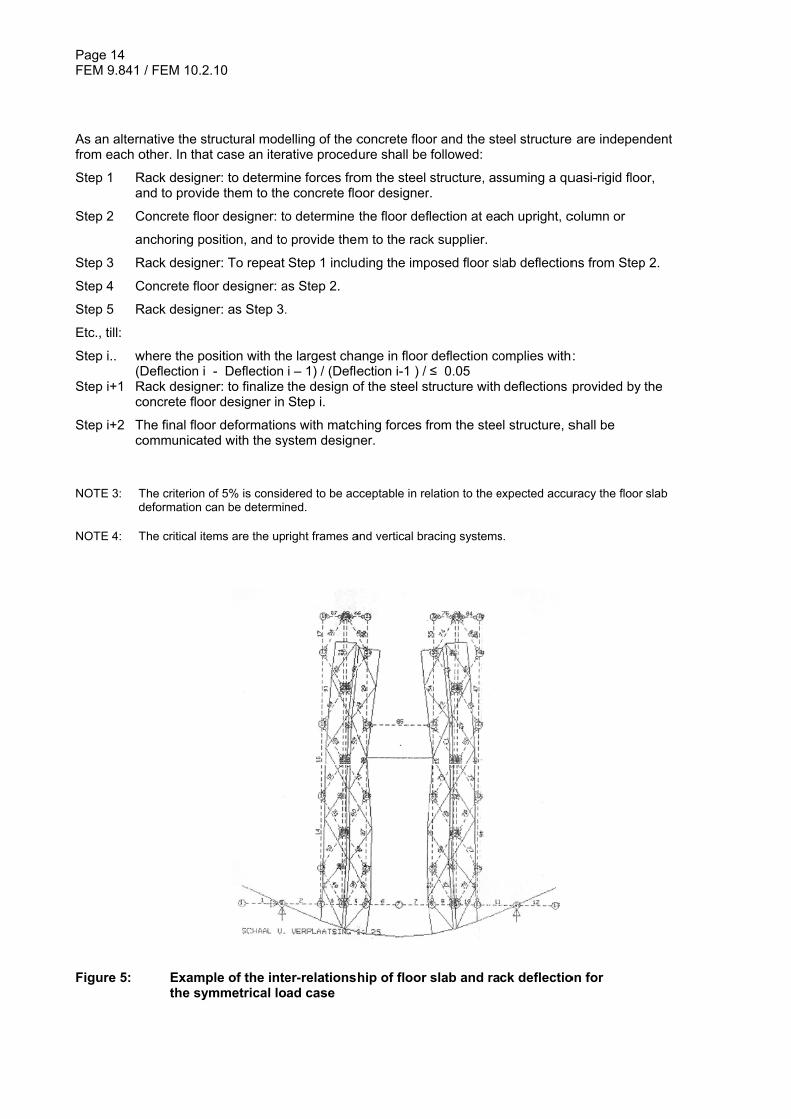
load q and resulting in deformations as deflection δ and angular rotation φ (3) In case the floor slab is not quasi rigid, the SD in cooperation with the end user shall coordinate the communication between the designers of the rack and concrete floor slab, because of the interaction between the two structures. Due to the floor deformations the rack loads will change which affects the floor deformations etc. It is an iterative procedure. In case not otherwise specified, one may assume that convergence is achieved when the change is less than 5%. NOTE 1: Geotechnical factors and / or non-homogeneous soils can cause non-uniform deformations of the floor
slab of many centimetres. NOTE 2: It might be desirable to model the foundation and rack structure by one interactive finite element
approach. When only a maximum angular rotation is specified, Figure 5 shows the worst case finite element model with resulting deformations for an intermediate picking aisle situation.
The proposed procedure is that the rack and supporting structure (slab/soil/piles) should be modelled in a single model. This requires that the slab designer and/or geotechnical engineer shall provide the rack designer with details of the soil/pile stiffness and the effective bending stiffness of the slab for inclusion in the rack model. The rack designer shall give the resulting reaction forces to the slab de-signer to check the design of the floor slab.
Page 14 FEM 9.841
As an alternfrom each o
Step 1 R a
Step 2 C
a
Step 3 R
Step 4 C
Step 5 R
Etc., till:
Step i.. w (DStep i+1 R co
Step i+2 T co
NOTE 3: T
d NOTE 4: T
Figure 5:
/ FEM 10.2.1
native the strother. In that
Rack designend to provide
Concrete floo
nchoring pos
Rack designe
Concrete floo
Rack designe
where the posDeflection i -
Rack designeoncrete floor
The final floorommunicate
The criterion odeformation ca
The critical item
Examplthe sym
10
ructural modecase an iter
er: to determie them to the
r designer: to
sition, and to
er: To repeat
r designer: a
er: as Step 3.
sition with th- Deflection
er: to finalize r designer in
r deformationd with the sy
of 5% is considan be determin
ms are the up
le of the intemmetrical lo
elling of the cative proced
ne forces froe concrete flo
o determine
o provide the
Step 1 inclu
as Step 2.
.
e largest chai – 1) / (Deflethe design oStep i.
ns with matchystem design
dered to be acned.
right frames a
er-relationshad case
concrete flooure shall be
om the steel oor designer
the floor def
m to the rack
ding the imp
ange in floor ection i-1 ) /of the steel st
hing forces fner.
cceptable in re
and vertical bra
hip of floor
or and the stefollowed:
structure, asr.
flection at ea
k supplier.
posed floor sl
deflection co≤ 0.05 tructure with
from the stee
elation to the e
acing systems
slab and ra
eel structure
ssuming a qu
ch upright, c
lab deflection
omplies with
deflections p
el structure, s
expected accu
s.
ck deflectio
e are indepen
uasi-rigid floo
column or
ns from Step
:
provided by
shall be
uracy the floor
on for
ndent
or,
p 2.
the
slab
Page 15 FEM 9.841 / FEM 10.2.10
5.4 Anchoring 5.4.1 Type of anchoring There are basically 3 types of anchoring: - cast in anchoring, to be designed by the concrete floor slab supplier. - cast in anchor pockets to allow for fine-adjustment of the anchoring position in the horizontal plane,
to be designed by the rack supplier. - post-installed anchoring. This can be either of the mechanical type (torque moment controlled) or
the adhesive/chemical type (resin bonded), to be designed by the rack supplier. In case of post-installed anchoring the slab designer shall at all anchor positions: - allow for drilling holes; - if possible avoid heavy reinforcement bars. NOTE: In general the anchoring of rack structures and their bracing system is post- installed, apart from rack
clad warehouses or racking in the heavier seismic zones, where cast in anchoring (or anchor pockets) might be needed.
5.4.2 Data needed for post- installed anchor design The design of post- installed anchors shall be in accordance with ETAG No 001. Therefore the floor slab designer shall inform the rack supplier about the following: - Concrete grade. - Guaranteed thickness of the structural concrete floor. - Concrete tension zones in the top of the slab as specified in ETAG No 001 over the floor slab area,
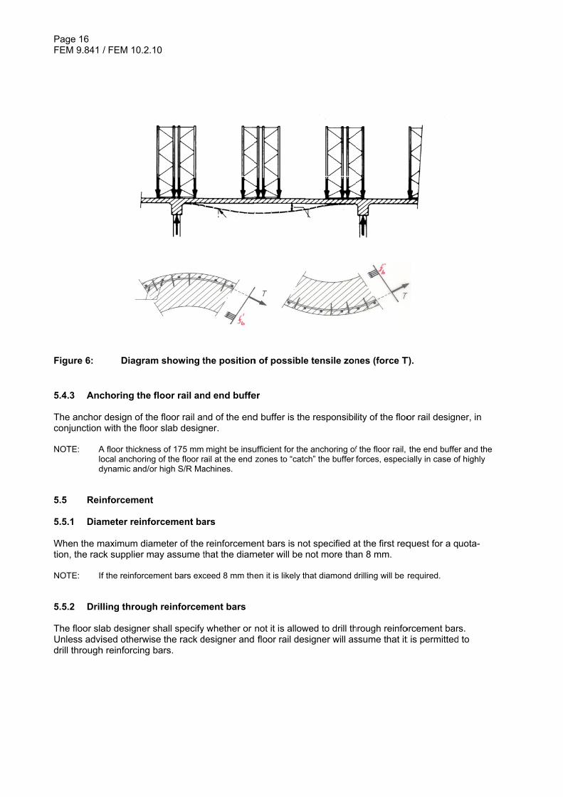
if any. In the case of a suspended floor there will be tension zones (see Figure 6). - Corrosive supplements (e.g. magnesite), if any. In case of such supplements the floor slab design-
er shall specify the required corrosion protection of the anchors as well as all steel components be-ing in direct contact with the concrete.
- Reinforcement detailing (diameter, spacing position to top side structural slab) - Position of movement joints (see 5.6) and/or saw cut joints. NOTE 1: The use of corrosive supplements such as magnesite or similar to the concrete mortar should be avoid-
ed. In case such supplements are used the floor slab designer shall specify the required corrosion pro-tection of the anchors, as well as all steel components being in direct contact with the concrete.
NOTE 2: ETAG 001 – Annex C, clause 4.1 says: If the tensile stress in the concrete is less than 3 N/mm2 then it may be assumed that the anchor is in the compression zone.
In the absence of a slab specification the rack designer shall assume the following for first dimension-ing and layout: - Concrete grade, at least C20 / 25. - Thickness of structural floor, at least 175 mm. - In case of a ground bearing floor slab: no tension zones, apart from the bracing system anchoring. - In case of a suspended floor slab: tension zones over the entire floor area. - No top screed. - No corrosive concrete admixtures.
For the final design the actual concrete properties shall be documented and communicated by the floor slab designer and considered by the floor slab designer and rack designer. NOTE 3: Crane racks typically use M16 anchors and these require a slab at least 175 mm thick. If thinner slabs
occur then special attention is required.
Page 16 FEM 9.841
Figure 6: 5.4.3 Anc The anchor conjunction NOTE: A
lod
5.5 Rei 5.5.1 Dia When the mtion, the rac NOTE: If
5.5.2 Dril The floor slaUnless advidrill through
/ FEM 10.2.1
Diagram
choring the
design of thwith the floo
A floor thickneocal anchoringdynamic and/o
nforcement
meter reinfo
maximum diack supplier m
f the reinforce
lling throug
ab designer ised otherwish reinforcing
10
m showing t
floor rail an
e floor rail anor slab desig
ss of 175 mmg of the floor ror high S/R Ma
t
orcement ba
ameter of themay assume t
ement bars exc
h reinforcem
shall specifyse the rack dbars.
the position
nd end buffe
nd of the endner.
might be insurail at the end achines.
ars
reinforcemethat the diam
ceed 8 mm the
ment bars
y whether or designer and
n of possible
er
d buffer is the
ufficient for thezones to “catc
ent bars is nometer will be
en it is likely t
not it is allow floor rail des
e tensile zon
e responsibi
e anchoring ofch” the buffer
ot specified anot more tha
hat diamond d
wed to drill thsigner will as
nes (force T
lity of the floo
f the floor rail, forces, especi
at the first reqan 8 mm.
drilling will be r
hrough reinfossume that it
T).
or rail design
the end buffeially in case o
quest for a q
required.
orcement bart is permitted
ner, in
er and the f highly
uota-
rs. d to
Page 17 FEM 9.841 / FEM 10.2.10
5.5.3 Steel fibre concrete At present there are design rules for ground bearing fibre reinforced floor slabs but there are no gen-erally established design rules for pile supported (suspended) fibre reinforced floor slabs. Also no de-sign rules are given for concentrated tension forces imposed by anchoring. NOTE 1: Examples of codes for ground bearing floor slabs are TR34 (UK), CUR 111 (NL).
NOTE 2: It should be noted that there are no “ETAG” certificated anchors in combination with steel fibre
concrete. However a design based upon non-reinforced concrete will probably give a conservative solu-tion. The supplier of the anchors should support the design.
5.6 Movement joints (1) If possible, movement joints shall be avoided. When movement joints cannot be avoided, suppliers of S/R-machines and the rack supplier shall be informed by the concrete floor slab designer about:
• position of the joint(s); • the horizontal displacement of the slabs at the joint. Two values are required. The first is the
displacement at the time the racking is installed across the joint. The second is the expected fi-nal joint displacement.
(2) Vertical movements of a movement joint are not allowed. (3) In case of movement joints perpendicular to the aisle, fixing and jointing of the floor rail and special detailing of the positioning system in down aisle (X-) direction is required NOTE 1: Depending on the rack properties (down-aisle bending stiffness of the uprights, distance between first
beam level and floor level, other beam distances) it might be necessary to have “independent” rack blocks on either side of a movement joint. Full independence is not possible, because the upper guide rail has to be continuous to avoid too high dynamic effects. This connection via the portal tie beam be-tween the 2 “independent” rack blocks should be considered in the rack design.
NOTE 2: Shrinkage and therefore joint opening can be minimised by attention to mix design and cement content i.e. lower cement content and not too low water / cement ratio. Higher reinforcement percentages permit movement joints to be more widely spaced or even avoided, as shrinkage cracking is controlled by the extra reinforcement i.e. there are many small cracks rather than a single larger movement at the movement joint.
Page 18 FEM 9.841 / FEM 10.2.10
6 Dynamic effects on components of the storage system 6.1 Dynamic effects (1) Due to running of material handling equipment like e.g. S/R Machines, shuttles, transfer cars, pallet conveyors there are: - inertia effects due to acceleration and deceleration , causing additional forces and a certain in-
crease of the static loading by dynamic factors; - load cycling effects possibly reducing the strength of steel components by fatigue effects. - vibrations effects (see 8). (2) The supplier of the material handling equipment shall quantify quasi-static horizontal and vertical forc-es directly acting on the steel component concerned (e.g. floor rail, upper guide rail, shuttle rail or rack supported “floor” rail). In quantifying this, it may be assumed that the tolerance and deformation re-quirements are met as specified in EN 15620 / FEM 9.831-1 and FEM 9.832. NOTE: Inertia and vibration effects induced by S/R Machines depend on many factors such as vibrations of the
engine, transmissions, lifting cable, lifting drive as well as wear and tear of drive and guide wheels, drive and guide rails as well as manufacturing and installation tolerances of S/R Machines, drive and guide rails as well as stiffness properties of S/R Machines, drive and guide rails, as well as driving speed.
(3) For the allowed floor rail and upper guide rail tolerances and deformations, which are relevant to dy-namic effects, see FEM 9.831-1 and FEM 9.832. For the upper guide rail see also 7.2.2. For the rack structure see 8.
6.2 Fatigue design - General (1) With the exception of the following items and unless specified otherwise by the SD it is not necessary to consider fatigue life time in the design of rack components (see figure 7);
• Upper crane rail and associated connections (i.e. connections between lengths of crane rail and connection of the rail to the portal tie)
• Portal tie and associated connections (i.e. connection of the portal tie to the rack uprights) • Beams supporting cranes (multi-level cranes) or transfer cars and associated connections (i.e.
connection of the beam to the rack uprights) • Flange with running surface of pallet shuttle rails • All running down aisle (shuttle) rails and associated connections • Supporting beams and associated members of a conveyor system
(2) The upper crane rail, portal tie, beams supporting cranes / S/R Machines and beams supporting trans-fer cars or conveyor system, along with their associated connections, shall be designed as fatigue endurable (“infinite” fatigue life time). “Infinite” fatigue life time in relation to the design life is defined as follows:
• A pallet stacker crane for running and stacking, 10 million load cycles • A small part stacker crane for running and stacking, 40 million load cycles
Page 19 FEM 9.841 / FEM 10.2.10
NOTE: In case of conveyor systems in reality the cyclic load situation might be better, because the chance that a “train” of ULs will pass at a certain moment rather than always individual ULs is relatively large. How-ever it is difficult to “translate” this in a lower number of design load cycles. Therefore also for conveyor belts “infinite fatigue life”.
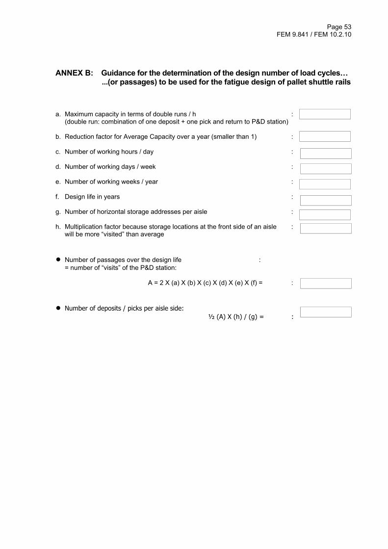
(3) The S/R Machine supplier shall specify the quasi-static loads and load combinations to be considered. An example is given in Annex A. (4) The flange with running surface and adjacent web part of pallet shuttle rails shall be designed for a specified number of shuttle passages (one passage is maximum loaded in and empty out or the re-verse). In this case the SD in cooperation with the S/R Machine supplier shall provide the rack supplier with:
• The number of shuttle passages (guidance might be given by Annex B). • The magnitude of the associated load.
NOTE: For an economic design of pallet shuttle rails, the local peak stresses due to the concentrated wheel
loads might be close to the steel yield stress. A fatigue check of the flange with the running surface and adjacent web part is in such cases always relevant, also in case of a relatively small number of load cycles.. Other parts of the pallet shuttle rail, its connections as well as the supporting down aisle beams need not to be checked for fatigue.
(5) The design for fatigue shall be based upon EN 1993 -1-9. For cold formed rack components con-cerned see FEM 10.2.13. (6) Unless specified otherwise by the SD the partial factor for fatigue shall be based upon the “safe-life method” (no regular inspections or difficult accessibility of the component) and “low failure conse-quence” (before real failure of a component with fatigue cracks there will be indications by e.g. noise of the running machine or increased deformations resulting in an operation fault signal to the storage system software). However, because of brittle failure behaviour of bolts for this component there will be no warning indication, bolts shall be designed for “high failure” consequence, unless a risk evalua-tion shows that timely warning will occur after failure of a bolt without failure of the total connection. If possible, the design shall avoid that failure of a bolt is determinative. “Safe live method” and “high” or “low failure consequence” are specified in EN 1993 -1-9. NOTE 1: In principle it is possible for more than one set of load and number of cycles to be specified (see figure 8),
however, in practice it is anticipated that only one set, based on the maximum loads, will be provided.
NOTE 2: Certain types of P&D stations support structure may need to be designed for fatigue and this will be stat-ed in the project specification.
NOTE 3: It is not necessary to design bracing systems for fatigue.
Page 20 FEM 9.841 / FEM 10.2.10
B
A
C
D
1 2
3
4
5
E
E
Key 1 Splice in upper guide rail 2 Upper guide rail to top tie connection 3 Top tie to upright connection 4 Crane supporting beam grid to upright connection 5 Pallet shuttle rail running surface flange A Portal tying of upright frame construction (reduces buckling length of the upright frame) NOTE: Rather than a standard top tie as shown in the left sided pair of upright frames B Upper guide rail C Pallet shuttle rail D Multi level crane supporting beam grid E Down aisle multi level crane “floor” rail Figure 7: Example of pallet racking with items and connections to be designed for fatigue Figure 8: Example of several sets of load with their design number of load cycles
(see EN 1993-1-9:2005, clause A.6).
Page 21 FEM 9.841 / FEM 10.2.10
6.3 Additional inspection prior to hand-over (1) The supplier of the steel component / structure is responsible for its quality. The proper execution (e.g. required quality and tolerance limits) of dynamic and fatigue loaded components is important. An in-spection procedure shall be agreed between parties for shop and site production and installation activ-ities as part of the hand-over. Guidance is given by EN 1090-2. NOTE 1: It should be noticed that complying with the tolerance limits is very important because if not it will lead to
much higher forces induced by the S/R Machines (e.g. upper guide rail). (2) Special attention shall be given to for instance:
- Welded or bolted joints. - Alignment and joint tolerances of the floor and upper guide rails. - Pre-loaded (“slip resistant”) bolted connections.
NOTE 2: In case fatigue is involved the actual weld quality is very relevant, In general Execution Class EXC 2 is
sufficient, which includes that: - a welding procedure specification is developed and test samples are prepared by the welders carrying out the work. - a sample, e.g. 10 % of the actual welds are subjected to dye penetrant or other form of Non Destructive Testing. When fatigue should be considered, formally EXC 3 is required for the welding, which implements e.g. more quality checks and slightly higher quality requirements. For storage equipment it was found that EXC 2 is sufficient.
6.4 Inspections during operation (1) For general regular inspections of the rack structure see EN 15635. (2) It is recommended to include a clause with regard to a visual check of the upper guide rail into the inspection manual of the S/R Machine.
Page 22 FEM 9.841 / FEM 10.2.10
7 Floor rail, End buffer and Upper guide rail 7.1 Floor rail and end buffer 7.1.1 General Dimensioning and selection of type of floor rail is the responsibility of the S/R Machine manufacturer. There has to be communication between the S/R Machine manufacturer, the floor slab designer and the supplier of the floor rail with regard to fixing the floor rail to the floor slab. Based on these data the supplier of floor rail can calculate anchors, rail clamps, footplates, etc. 7.1.2 Loading (1) The floor rail serves to distribute the static and dynamic (when moving) wheel loads and provides guidance to the S/R Machine. The quasi-static wheel loads resulting from static and dynamic effects, shall be specified for the situation when moving. In case the S/R Machine is equipped with anti-tipping devices, which engage the rail heads, the floor rails (incl. corresponding fixing elements and associat-ed parts) shall be able to withstand the resulting forces, which shall be specified by the supplier of the S/R Machine. (2) The position and magnitude of the quasi-static forces from a buffer impact shall be specified by the supplier of the S/R Machine. Unless specified otherwise by the supplier of the S/R Machine the buffer load case shall not be considered as an accidental load case. (3) If the buffer is regularly activated as part of the normal system operation it is allowed to neglect this load case if the value of the force is less than 10 % of the buffer impact force. 7.1.3 Methods of fixing (1) The manufacturer of the S/R Machine shall specify the spacing of the floor rail fixing. The supplier of the floor rail has to determine the proper fixing. In case corrosive additives are added to the concrete mortar (see 5.4.2). (2) In case grouting at the anchoring points is required, adequate connection between floor slab and grouting shall be ensured by a sufficient surface roughness (by brushed surface, preferably not power troweled). The method required shall be agreed between parties. (3) If grouting is carried out when the temperature is quite low then the grout used shall be appropriate for the temperature range. (4) For drilling through reinforcement bars (see 5.5.2). 7.1.4 Tolerances and deformations floor rail Reference to FEM 9.831-1 and FEM 9.832.
Page 23 FEM 9.841 / FEM 10.2.10
7.1.5 Supplementary equipotential bonding (earthing) In order to prevent hazardous conditions due to isolation failures between live parts and exposed con-ductive parts the floor rails shall be connected by the electrical installation supplier of the warehouse building to the overall supplementary equipotential bonding in accordance to IEC 60364-4-41: 1992, Chapter 413.1.6. 7.2 Upper guide rail 7.2.1 Tolerances and deformations Reference to FEM 9.831-1 and FEM 9.832. 7.2.2 Guide forces when moving (1) The supplier of the S/R Machine shall specify the: - design value of the quasi-static guide force when moving, considering possible tolerances and
deformations (see EN 15620 / FEM 9.831 Part 1 and FEM 9.832); - the design value of the quasi-static guide force over a curved track to change aisles, if any. NOTE 1: Due to the increasing speed of the S/R Machines, it has become common practice to mount the guide
wheels without any gap to the guide rail in order to reduce wear and tear of the tyres. This affects the forces from the guide wheels into the rack structure and these forces are present at each passage.
NOTE 2: Assuming a quasi-rigid support at the rack structure will probably result in a safe dynamic factor ap-
proach in determining the quasi-static guide force. Because of the inertia effects of the masses of the stored goods, this will probably be near to reality. In case not all end conditions can be quantified a conservative approach should be chosen.
(2) Apart from the dynamic effects during moving, the guide force(s) on an upper guide rail are also de-pendent on the following factors: - In case there is more than a single pair of (rigidly connected) guide wheels, then the torsional stiff-
ness of the mast will induce additional (unintentional) wheel forces (see figure 9). - Is it a one or two mast S/R Machine. In case of a two mast S/R Machine a non-parallelism toler-
ance between the two masts will induce an additional unintentional guide forces during moving. - In case the centre of gravity of the S/R Machine with and without load is not in the plane through
the floor rail, there is always a static guide force to prevent tilting of the S/R Machine (see figure 10).
- Whether or not there is an eccentric drive. In case such factors are present, one shall account for their effect on the guide forces.
Page 24 FEM 9.841 / FEM 10.2.10
Key 1 top view upper guide rail 2 guide wheel 3 lateral guide force per wheel in – Z direction (5 = 0) 4 distance between 2 pairs of guide wheels 5 lateral guide force per wheel in + Z direction (3 = 0) 6 wheel force due to mast torsion restrain, in case of a rigidly connected pair of 2 (7 = 0) 7 see 6, but counter acting (6 = 0) Figure 9: Guide wheel load configuration, in case of a rigidly connected pair of 2 guide
wheels (Torsion restraining moment = (6 - 7) x 4).
Key 1 Distance between centre of gravity S/R Machine plus load and vertical plane through floor rail Figure 10: In case of situation (b) also in the static situation there is a guide force: Hls
(a) Centre of gravity in plane through upper guide and floor rail
(b) Centre of gravity S/R Machine plus load with eccentricity “1”
Page 25 FEM 9.841 / FEM 10.2.10
7.2.3 Guide forces when depositing / picking The supplier of the S/R Machine shall specify the: - quasi static lateral support force when depositing / picking; - position of the guide wheels with respect to the centre of the storage location to be intended for the
depositing/picking. 7.2.4 Design of the upper guide rail and its splice connections The supplier of the S/R Machine is responsible for the design of the upper guide rail and its splice connections, as well as for the position of the splice connection with regard to the rack top tie beams to which the upper guiderail is connected at each cross aisle row of upright frames Because the execution quality of the splice connection is a parameter in the design, the supplier of the S/R Machine shall also specify the pre-treatment of the splice and the execution quality required (guidance is given by EN 1090 – 2). The supplier of the racking is responsible for the design of the connection between the upper guide rail and portal tie beam, based upon the forces specified by the S/R Machine supplier. NOTE 1: The mast detailing and whether or not there is a traction drive determines the rail design. Also the speci-
fication of the quasi-static guide forces is related to the S/R Machine. Therefore this design to be done by the supplier of the S/R Machine.
NOTE 2: The supplier of the racking or shelving remains responsible for checking the deformations, because
these deformations are also influenced by the top tie beam section. See FEM 9.831-1 or FEM 9.832. To comply with the deformation limits given in these FEM Codes, an additional mid-bay top tie beam might be required.
7.3 Horizontal drive In case of S/R Machines inducing down aisle horizontal forces on the guide rail, these shall be speci-fied by the S/R Machine supplier. In case of S/R-machines supported by the racking for the induced forces and other end conditions, see 10.13. 7.4 Rack mounted end buffer (1) In case a S/R Machine buffer is mounted on the upper guide rail or to the rack, the maximum expected buffer force shall be specified by the supplier of the S/R Machine. Unless specified otherwise by the supplier of the S/R Machine this load case shall not be considered as an accidental load case by the rack designer. (2) In the case of rack clad structures the buffer force need not be considered at the same time as the wind load. NOTE: A buffer stop has to be considered as a “normal” load case to prevent the need to adjust the buffer and
supporting structure after each activation.
Page 26 FEM 9.841 / FEM 10.2.10
8 Vibration of the rack (1) With reference to EN 528 : 2008, clause 5.10.7.3, the SD shall consider the possibility of unintended load movement due to possible vibrations. The end user should be aware that it is practically impossible to predict this at the design stage. Experience suggests that this can be a particular problem where the stored loads are relatively light and the damping due to the stored goods is small, e.g. small parts racks. Possible measures to prevent unintended load movements are for instance to incorporate features that increase the coefficient of friction between the UL and the supports or incorporate devices that restrain the ULs in position or having an angle of the UL support away from the crane aisle. (2) However under conditions of installation tolerances of the floor rail and upper guide rail complying with FEM 9.831-1 or FEM 9.832 and of the upper guide rollers assembly quality and limitation of wear and tear by maintenance complying with the specification of the S/R Machine supplier, the damping behav-iour of a rack structure can be assumed to be sufficient to prevent UL movement by vibration. It may also be assumed that due to “normal” operations there will be no loosening of bolted connec-tions when tightened professionally according to common practice. NOTE 1: A securing method of bolted connections used in practice of many years and showing no loosening under
operational conditions, is the “Snug tight” type as specified in EN 1090-2. In combination with nuts with “toothed flanges” or prevailing torque nuts (e.g. “nylocs”). “Snug tight” will be achieved by the effect of one man using a normal sized spanner without an extension arm, or the bolted connection is set to the point at which a percussion wrench starts hammering.
NOTE 2: Special attention is required for bolted connections between upper guide rail and cross aisle portal tie
beams, because in general there will be slotted holes.
Page 27 FEM 9.841 / FEM 10.2.10
9 Unit load (Specified load) 9.1 Load make-up accessories (LMA) (1) Safe support conditions of the LMA shall be agreed, taking into account the allowed worst case LMA condition and the maximum depositing tolerances to be expected (2) In order to provide operational safety and reliability the specification of the load make-up accessories (e.g. pallets, box containers, totes and bins) has to be a part of the system specification:
a. Dimensions and tolerances to be in accordance with the “tolerances, deformations and clear-ances” considerations (see EN 15620 / FEM 9.831 – Part 1 or FEM 9.832).
b. The quality and level of maintenance to be such that operational safety will be not endangered and the deflection will be in accordance with the limit value as assumed in the “tolerances, de-formations and clearances” considerations.
c. Material of the LMA(s). NOTE 1: Poor quality load make-up accessories will negatively affect system reliability as well as operational safe-
ty (possibility of local failure of rack components or even a progressive rack collapse). It should be noted that apart from the quality in daily practice also dimensions and tolerances may differ from standards as EN 13698 Parts 1 and 2 for wooden “Euro”-pallets. The European chemical industry has developed spe-cial pallet types (see e.g. CP-Chemical industry pallets; [10]). Even pallets complying with these stand-ards might require additional considerations for fault free operation.
NOTE 2: In case of wooden pallets, dimensions and deflection are changing with time due to shrinkage and creep behaviour and possible changing “arch”-action of the goods on the pallet, affecting the safe picking. Special attention is required. In case it is intended to store wet wooden pallets, deflection and strength are not controlled anymore. Additional pallet supports might be required to ensure safe support and operation.
NOTE 3: In case of plastic pallets: - in general dimensions, tolerances and mechanical properties (deflection and strength) are not har-
monized (no standards or certified manufacturer data sheet); - there will be additional deflection with time due to creep; - in general there will be a small friction coefficient which might make them “slippery”.
Special attention is required.
NOTE 4: Actual LMA types and qualities could lead to the conclusion that sufficient fork entry space is not en-sured. Safe operation conditions can in such cases only be maintained when special measures are taken like slave pallets, a “third” rack compartment beam or shims at the LMA bearings.
NOTE 5: In case of small parts storage, special attention should be paid to the following properties of the totes or bins to be stored:
- shape of the edges (e.g. conical; stackable); - the deflection of the edges; - the deflection of the bottom side.
NOTE 6: Special attention is required for the support conditions of “soft” LMAs, e.g. cartons, because of the possi-bility of increased “bedding-in” with time.
Page 28 FEM 9.841 / FEM 10.2.10
9.2 Weight of the UL 9.2.1 Minimum and maximum weight (1) The minimum and maximum weight of a UL shall be specified. Unless specified otherwise the centre of gravity will be assumed to be at the geometrical centre. (2) For the application of the reduced load factor as specified in EN 15512, the end-user shall ensure that in daily operation the specified maximum weight of the UL will never be exceeded. This shall be sup-ported by:
- either a written statement by the end-user (issued to the system designer) that the nature of the goods to be stored over the design life time of the storage system means that it is impossible to exceed the maximum weight specified.
- or a weighing device at the point where the UL enters or re-enters the storage system, with a measuring accuracy of 5% or better. The operation manual shall state that this weighing unit is crucial to the safety of the system and shall not be removed or disabled. ULs heavier than the specified maximum shall be rejected. The value for the maximum weight of the UL to be used in the design shall be under this condi-tion 1,05 x the maximum weight specified in (1).
NOTE 1: It is not allowed to consider the S/R Machine overload protector as a weighing device in the above
context.
NOTE 2: The given factor of 1,05 implicates in combination with EN 15512 that with regard to the UL a total partial safety factor has to be considered of: 1,05 x 1,3 = 1,365.
9.2.2 Differentiation of design weights (1) It is possible that different statistical “families” of ULs are stored, with each their own storage level(s) with matching compartment height. For each “family” different maximum weights of the ULs might be specified. (2) In case of storage of ULs with a relatively high scatter in actual weights, it may be decided for a differ-entiation of design weights depending on the rack component(s) concerned, as:
- Structural components part of the rack compartment (maximum weight always to be considered). - Upright frames. - Run of bays.
In case no differentiated specification is given, the specified maximum weight of the ULs shall be con-sidered for the design of all rack components. (3) Differentiation of design weights shall be based on reliable statistical data or a strategy for the alloca-tion of ULs by the warehouse management system. This results in the specification of different design weights which will never lead to overloading of the rack component concerned. With regard to safe guarding upright frame loading in daily operation the WMS shall consider the part of the UL weight to be supported by the upright frame concerned considering beam splice configurations (see Annex D). NOTE: Designing a WMS sufficiently reliably in accordance with the Machinery Directive for all possible situa-
tions of positions of beam splices and UL positions is complex. Therefore due consideration shall be given to the decision for specifying differentiated design weights. The outcome might be to design for no load reduction in designing the upright frames.
(4) In case for load reduction is chosen this shall be indicated in the operation manual of the storage sys-tem as well as on the load warning sign with regard to the rack structure.
Page 29 FEM 9.841 / FEM 10.2.10
NOTE 1: In project specifications sometimes 2 values are given in relation to the weight of the UL: • The maximum value. • The average value. However it will be obvious from (1) and (2) that such an average value deter-
mined at a certain moment from a certain number of ULs being part of (a) certain statistical fami-ly(ies), is not allowed to be used as design weight. In case load reduction for e.g. the upright frame design is considered, the reduced sum of UL weights should be determined in a conservative way (never in conflict with future operation). To be sure a management system should be in place (see (3)).
NOTE 2: In the case of a double deep rack the SD should consider whether the “rated average” bay load can be applied to both the front & rear positions or that differentiation is required to consider the sum of the weights of the ULs at the front end rear positions separately. In principle it is possible to specify different reduced weights for all front positions and all rear positions in a bay. Unless specified otherwise the rack design will be based on same reduction percentages for the front and rear positions.
NOTE 3: In case the SD in cooperation with the end user has decided for a load reduction with regard to the up-right frames, this implicates that there is also a reduction of the flexibility of allocating ULs to storage locations: meaning a reduction of the effective storage capacity.
9.2.3 Sprinkler water It is hardly not possible to specify a reliable accidental load case of increased weight of ULs over a certain rack volume, due to water when the sprinkler system is activated. In general such a load case is not considered and a possible collapse is accepted. NOTE: In the case of miniload systems in particular taking into account containers full of water or soaked cartons
is likely to result in more expensive rack systems. The need for this should be considered by the end user on a project by project basis.
9.3 Dimensions of the UL (1) The goods stored on the LMA might protrude outside the perimeter of the LMA (see figure 10a). The SD in cooperation with the end user shall specify the overall dimensions of the UL. Figure 10a: Examples of overhanging goods outside the perimeter of a LMA, with their
dimensions for the design of the storage system when maximum (2) It is possible that the load overhang is not symmetrical. This will cause a shift of the centre of gravity with regard to its nominal position (see figure 10b). In general, when the asymmetrical load overhang is limited, this shift can be neglected for the design of a storage system. However in case of double deep pallet racking the effect on the load shearing of the telescopic forks resulting in an additional UL-movement in down-aisle (X-) direction (see FEM 9.831-1) might not be negligible (more fork deformation) and will affect the clearances concerned. The SD in cooperation with the end user and supplier of the S/R Machine shall consider this. NOTE: Especially in case of pallets with a small width, e.g. 800 mm in which case b = 375 mm (see figure 10b),
the difference in load on each fork will not be negligible also in case of an overhang of e.g. ”only” 50 mm: the higher fork load is appr. 30% above the lower fork load!
Page 30 FEM 9.841
Figure 10b
9.4 Sta (1) The stability- safe mov- that the a the spec (2) In case the 9.5 Sto In case hazcerned. 9.6 Mor In case of mtionally to ththeir design
/ FEM 10.2.1
: A linearof grav
bility of the
y of the goodving; actual overa
cified maximu
building site
orage of haz
zardous good
re than one
more types ofhe relevant pn placement t
10
r asymmetrity of ½ a
goods on a
ds on an LMA
ll dimensionsum overall di
is an earthq
ardous goo
ds have to be
type of UL
f ULs to be sproperties of tolerances in
ic overhang
an LMA
A, e.g. pallet,
s of the UL inimensions to
quake area (s
ds
e stored, atte
per location
stored in the each type of
n X- and Z- d
g of a mm re
, shall be suf
n all stages oo be used in t
see 10.6), re
ention shall b
n
same locatiof UL: the nomdirection.
esults in a s
fficient in ord
of storing anthe design.
eference is m
be paid to the
on, the followminal stored
hift of the ce
der to ensure
d retrieving w
made to FEM
e national reg
wing has to bposition of ea
entre
e:
will remain w
10.2.08.
gulations con
be specified aach as well a
within
n-
addi-as
Page 31 FEM 9.841 / FEM 10.2.10
10 Rack structure For general guidance to the design specification of the rack structure, see EN 15629. 10.1 Operation safety; Tolerances, deformations and clearances (1) With regard to the determination of the minimum clearances needed on the basis of specified possible tolerances and deformations to ensure safe automated operation, reference to EN 15620 / FEM 9.831-1 and FEM 9.832. (2) Prior to the installation of the rack structure, a mutual acceptance is required between SD and rack supplier of the relevant datum which are physically indicated at site:
- System datum axes in down aisle (X-) and cross aisle (Z-) directions; - System datum Y level, which might be the highest point of the warehouse floor area concerned.
(3) For specific safety measures and/or devices, see 10.3. (4) Operation shall be in accordance with the design specification. An Operation and Maintenance Manual shall be in place. See 12. 10.2 Structural safety (1) The structural design of the pallet rack shall be based upon EN 15512. In case of rack clad ware-houses one shall comply with the national building regulations. NOTE 1: Germany and the Netherlands have an A-Deviation to EN 15512. It should also be noted that in EN
15512 the partial safety factors are based upon the recommended values specified in Eurocode 3. The “National Annexes” to Eurocode 3 might specify higher partial factors.
NOTE 2: A specific situation is when the S/R Machine is supported by the rack structure, also in terms of defor-
mation limits. See also 10.13. (2) All relevant actions induced by material handling equipment in terms of quasi-static forces shall be specified by the supplier(s) of the equipment. With regard to fatigue related actions, see 6. (3) Relevant information shall be part of the operational & maintenance manual. Reference to 12. 10.3 Safety measures and devices 10.3.1 Fencing Requirements for the dimensioning of fencing in relation to safe guarding for hazardous situations are given in ISO 13857. 10.3.2 Grating In case flooring is integrated in the rack structure and consists of grating, the dimensions of the open-ings depends on the activity below and shall comply with EN-ISO 14122 – 2.
Page 32 FEM 9.841 / FEM 10.2.10
The SD shall specify whether or not below the flooring concerned persons only temporarily or regularly are present. NOTE : EN-ISO 14122-2:2001: In case persons .are present on a regular basis, the dimension of the openings
shall be such that a ball with a diameter of 20 mm will not fall through. Otherwise this diameter is 35 mm.
10.3.3 Safety back stops (1) The clearance in the cross aisle (Z-) direction between a safety back stop and the deposited UL shall be such that for normal operation the back stop shall never be touched: it is a safety back stop. For pallet racking see also 10.6. (2) For the design of pallet safety back stops see also FEM 9.842 / 10.2.11. 10.3.4 Buffer back stops In some specific cases the safety back stop has also a function under “normal” depositing/picking (e.g. in case of special mini load systems and some storage locations of crane operated systems). In such cases they are as well a buffer back stop and the rack supplier shall be informed by the SD in cooperation with the S/R supplier accordingly, together with regard to the quasi static buffer force to design for and how to consider the load cycling fatigue effects.. NOTE: The general safety requirements and those for the design of safety devices (e.g. sensors, electrome-
chanical devices, screens, nettings, gratings, physical safety backstops) are specified in e.g. Machinery directive, EN-ISO 12100-2, EN 528, EN 60204 -32 and in EN 619. In case EN 528 gives insufficient quantified information for a specific situation (e.g. protection against falling goods into a pedestrian or traffic area; the interface between manual order picking and moving S/R Machines), the SD shall coordinate acceptance by the health and safety authority.
10.4 Possible obstructions (1) An optimal rack layout and / or configuration might not always be possible, for example due to:
• columns of the warehouse building; • installations in the warehouse, e.g. for heating, air circulation, sprinkler; • lateral deformations of the warehouse building in case of an indoor rack • escape routes; • conveyor system design; • inspection cover in the floor.
(2) The SD shall coordinate with the end-user such possible constraints between the storage system de-sign and warehouse building design. NOTE: Taking care that the final situation of obstructions is known in due time, prevents potential additional
costs and lost of time for parties involved. 10.5 Grouting If grouting is done to level the base plates, the grout used shall have negligible shrinking and be ap-propriate for the agreed minimum application temperature. The concrete floor shall have no water on it. NOTE: It should be noted that below a certain temperature, in general +5 0C, grouting is not recommended.
Below 0 0C it is not allowed without special shelter as is the case for pouring concrete mortar.
Page 33 FEM 9.841 / FEM 10.2.10
10.6 Building site in an earthquake area 10.6.1 Exact location and necessity for a seismic design When the site is in a country with earthquake areas the exact location of the site shall be specified, preferably by postal code or geographic coordinates. From this exact location it is known whether or not the load case “seismic actions” shall be considered. NOTE 1: The exact location is also required to determine the Seismic Zone or mapped spectral response accel-
erations. NOTE 2: At least because of legislation with regard to “Safety of workers at work”, the employer may be obliged
to have in the project specification the requirement to consider in the design the consequences of the specified design earthquake for the site concerned. Not all employers are aware of this.
10.6.2 Weights of the ULs to be used in the design Based upon a statistical evaluation lower design weights, may be specified in the case of earthquake design. This has to be coordinated by the end user. Unless specified otherwise, the rack supplier shall consider the specified maximum weight. 10.6.3 S/R Machines (1) There are no known and agreed general methods of seismic design for the S/R Machines. Possible damage to the S/R Machine is accepted, however the S/R Machine shall not fail assuming the lateral support by the rack structure remains intact. (2) In the event of an earthquake the operating conditions such as for instance required clearances in-cluding seismic sways and interacting forces will not be within required limits for safe operation and this will give substantial risks when operating an S/R Machine during an earthquake. Based upon a risk analysis a measure needed might be a seismic activity detection system in order to stop the S/R Machines immediately after the detection of an earthquake with an intensity higher than a percentage of the design earthquake, to be specified by the SD in cooperation with the end user. NOTE: Threshold percentage could be in the order of 10 – 30 %. (3) The SD shall consider and coordinate appropriate actions between end user, warehouse supplier, rack supplier and S/R Machine supplier. With respect to seismic system design the S/R Machine supplier may need to specify machine data such as mass, centre of gravity and stiffness for significant parts of the machines. (4) Because the S/R Machines involved can stop at any position in down aisle (X–) direction; see (1), the following cases, not simultaneously, shall be taken into account in the design of the racking:
- Maximum 3 operating aisles: 1 crane with its LHD at the top most position, maximum loaded. - Maximum 6 operating aisles: 2 cranes with their LHD at their top most position, maximum loaded. - More than 6 operating aisles: 3 cranes with their LHD at their top most position, maximum loaded. - In case of multi-level cranes not only the top most position shall be considered but also the low-
est position of the LHD. - All cranes are in the conveyor entrance position, not loaded.
Page 34 FEM 9.841 / FEM 10.2.10
10.6.4 Rules for the structural design of the rack structure The national standard on seismic design of construction work shall be applied. When no specific rules do exist for pallet racking structures, it is allowed to use the FEM 10.2.08. For other types then pallet racking the principles given in FEM 10.2.08 can be used. NOTE 1: In certain European countries, e.g. Germany, the national standard for seismic design of steel structures
might specify different ductility factors to FEM 10.2.08. NOTE 2: In general it is possible , also for “medium and high seismic activity”, to agree upon Execution Class EXC
2 (see EN 1090-2). See also 6.3 (2). NOTE 3: In the USA for seismic actions and design reference is made to the RMI Specification /
ANSI Code MH 16.1. 10.6.5 Additional design data needed. (1) The following additional design data are needed for the seismic design of the rack structure (see FEM 10.2.08 and Annex C):
a. Rated pallet weight for seismic design (see also 10.6.2). b. Rack filling grade reduction factor. c. Sub soil characteristics / Ground type. d. Importance class of the installation (see Table 1). e. Seismic sway of the warehouse building, in case of an indoor – rack. f. Stored goods class (compact / constrained or relatively weak or loose / unconstrained or liq-
uid) for the determination of the pallet weight modification factor. g. Type of load make up accessory and environment, as:
- wood, dry environment; - wood, wet environment; - yes or no a cold store environment; - plastic, any environment; - steel, any environment.
The design life for the load case “Seismic”. In case of 30 years or less instead of 50 years, it is allowed to use a reduced importance factor (see Table 1). NOTE: The following indication can be given for the stored good class:
• Compact / Constrained. Examples: - Frozen goods (cold store) - Steel sheets or coils - Paper rolls
• Weak. Example: - Wrapped palletized items to a height relatively high compared to pallet size
• Loose and unconstrained. Example: - Goods that can easily move around inside the container e.g. granulated materials
• Liquid. Example: - UL containing liquid that can slosh in the container.
Page 35 FEM 9.841 / FEM 10.2.10
Table 1: Importance factors for seismic design of racks (reference to FEM 10.2.08)
Importance Class Description (*) Importance factor
Nominal Reduced
l Warehouses with fully automated storage operations. Low warehouse occupancy 0.8 0.67
ll Normal warehouse conditions, including picking areas 1.0 0.84
lll Retail areas with public access 1.2 not appl.
lV Hazardous product storage 1.4 not appl.
(2) Warehouse conditions ((*) from Table 1) In general only authorized and trained workers are permitted to access the storage area(‘s) within a warehouse. Low warehouse occupancy for a certain storage area is defined as an operation condition where no more than 5 authorized and trained workers can operate at one time within that storage area. In relation to the determination of the importance class for the storage area concerned, a storage area is defined as follows: Width x Length = (A + h) x (B +h) Where, A = width of plan view of rack block B = length of plan view of rack block h = maximum height of rack with ULs In case the rack is closer to a warehouse wall than “h”, the storage area border at that position is the warehouse wall.
In case the storage area concerned is adjacent to another warehouse compartment and the rack with ULs is at least 2 times higher than the adjacent compartment, the workers present in this lower ware-house compartment shall be included when determining the number of simultaneously present work-ers. For instance in case of a high bay racking separated by an inner wall or a rack clad building adjacent to an order pick area (see e.g. figure 11). The Warehouse Safety Manager, considering the risk associated with the working conditions of the warehouse, may prescribe a more severe importance class. For importance classes III and IV a reduction of the importance factor for racks is not permitted
Page 36 FEM 9.841 / FEM 10.2.10
Key 1: Order Pick area 2: High bay warehouse Figure 11: Adjacent logistic building to the high bay warehouse 10.6.6 Storage system check after an earthquake After an earthquake there might be certain damage. An additional maintenance check is recommended. An inspection of the condition of the S/R Machines, of the rack structure and of possible not allowed dislocation of the ULs resulting in too small clearances or unsafe support conditions, is required when (see FEM 10.2.08): ag;published > apr where, ag;published Relevant acceleration type measured, published by the authorities apr Limit value for ag;published, to be specified by the rack supplier in accordance with FEM 10.2.08 NOTE: The end user is responsible for ensuring this in daily use. The SD should provide the adequate infor-
mation. 10.7 Distribution of ULs over the rack volume (1) Unless specified otherwise by the SD in cooperation with the end user it is allowed to assume a uni-formly distributed storage load over the rack volume for the seismic design of the rack structure, for the global seismic analysis. (2) Special attention is required in case different mass distributions are possible over a longer period, for example comparing the logistic ABC – zones. In case relevant such distribution shall be specified by the system designer. NOTE: If it is possible that a relatively large rack volume (e.g. an aisle or a number of bays) is substantially load-
ed with smaller weights or even unloaded over a longer period regularly occurring over the design life, this will have a relevant effect on the eigenfrequency of the rack as well as on the tension forces to be taken by the concrete slab.
Page 37 FEM 9.841 / FEM 10.2.10
10.8 Relative depositing tolerances - Excluding small parts racking (1) A relative depositing tolerance is the effect of tolerances and deformations of all sub-systems con-cerned, resulting in a shift of the UL to be deposited in down aisle (X-) and cross aisle (Z-) direction with regard to its nominal (“ideal”) position in relation to the rack structure. (2) For general information see Annex E of EN 15620. (3) In the first stage of the design, the rack designer may assume that the relative depositing tolerances in the down aisle (X-) and cross aisle (Z-) direction will not exceed 50 mm. In this case safe support of the UL shall be given and the safety back stop, if any, shall not be touched. The final concept shall be based upon the finally agreed relative depositing tolerances. 10.9 Support condition of a pallet in a single deep pallet racking In case not otherwise agreed, the protruding part in cross aisle (Z-)direction of a pallet outside the pair of supporting beams of a single deep pallet racking, shall be in accordance with FEM 9.831 – 1, in order to limit the pallet deflection. 10.10 Double deep pallet racking 10.10.1 Pattern loading in a double deep pallet racking (1) In case it is a possibility that the Warehouse Management System (WMS) will “instruct” the S/R Ma-chine to pick only from the first deep storage position in order to have the quickest retrieval of ULs, the following pattern loading shall also be considered in the rack design: At all levels and in each 2 adjacent bays in the second deep position all locations are maximum load-ed and the same locations in the first deep position are not loaded. (2) The SD might specify that the pattern load case as given in (1) will not occur. When not specifically specified, the rack designer shall consider this additional load case. (3) In case the double rack runs are tied to each other not only at the top of the upright frames but also at intermediate levels the pattern loading will in general not result in additional upright frame bending to be considered in the determination of the aisle clearances (see FEM 9.831 – 1). The tie members and their interaction with the tied upright frames shall be also designed for the pat-tern load case given in (1). (4) The rack supplier shall check for the single rack runs that the maximum bow deflection of the upright frame with the 2 adjacent bays pattern loaded complies with the specified limit value for this bow de-flection (see e.g. FEM 9.831-1). (5) Because of the highly temporarily character of this pattern loading, it needs not to be combined with wind loads when these loads have to be considered.
Page 38 FEM 9.841 / FEM 10.2.10
10.10.2 Faulty depositing in a double deep pallet racking The load case shown in figure 12b shall be taken into account as an accidental load case considering the maximum nominal weight of the UL, possible due to unintentional accidental load movement. NOTE: Situation (b) in figure 12 is only possible when operating in a manual mode. It is allowed to consider
situation (b) as an accidental load case with the possibility of residual deformations, because when the S/R Machine is retrieving the UL from this location in the automatic mode, there will be always a fault signal to the operating system.
Key 1: Top hat or Cross bar Figure 12: A normal loading condition is shown in (a). In (b) the worst case accidental load
case is shown with regard to the top hats or cross bars 10.10.3 Load transfer from UL to top hat / cross bar In designing the top hat / cross bar one shall also consider the effects of deflection of the load make-up accessory (e.g. pallet) and of down aisle (X-direction) placement tolerances 10.11 Data for the design of the shuttle rail in shuttle pallet racking (1) The shuttle rail shall be designed to carry the deposited ULs as well as an empty or fully loaded shut-tle, whichever gives the worst load condition. In designing the shuttle rail it is allowed to neglect effects of rail torsion due to the position of the wheel loads with regard to the shear centre of the rail and horizontal rail bending, because of a combination of positive effects due to friction and the horizontal guide wheels. (2) To design the shuttle rail for the moving shuttle, the S/R Machine supplier shall provide the following data: a The quasi-static wheel loads to be considered for the fatigue analysis (see figure 13). One load
cycle is defined as a shuttle passage: shuttle entering the lane empty and returning maximum loaded to the crane, or vice versa.
b The closest position of the set of wheels to the end of the rail, when the shuttle is entering or leaving the lane.
c The worst case (maximum) wheel distance from the rail web, to be considered in the fatigue analysis. d The contact area of the wheels with the running surface and its position. e Maximum allowed height of a possible upward lip of the bottom flange of the rail. f Force on entrance guidance. In case of a horizontal and/or vertical shuttle guidance for entering
a lane, this component is in general meant as a non-intentional help. Therefore it is permitted to neglect any force induced by a guidance, if not specified otherwise.
Page 39 FEM 9.841 / FEM 10.2.10
NOTE: To avoid high stresses of the rail at the lane entrance (see figure 14), the lifting carriage should be above the rail running surface in every situation during the loading / unloading sequence of a lane. See figure 15. It is assumed that when the shuttle leaves the rack lane (figure 15 b) the wheel load F1 will decrease while wheel load F2 will increase with the same amount due to increasing rail run-ning surface deflection at the wheel with F1 when approaching the rail end. It should also be noted that in case the S/R Machine carriage running surface is not always above the running surface of the rail, there will be also an increased wear of the wheels.
Key 1 Contact area b x c, to be defined a Maximum possible distance between a wheel load and the web of the shuttle rail Figure 13: Example of a wheel load arrangement of a pallet shuttle with at each side
4 wheels. It is a statically undetermined system, in general requiring a con- servative arbitrary specification
Key 1 Effective contact area wheel to running surface 2 Axis of symmetry (example given is wheel at mid span) Figure 14: Relatively high peak stresses in the shuttle rail will be at the concentrated wheel
load. In case the wheel with its full load might be at the rail end, such peak stresses will be appr. twice as high.
(3) In case of pick tunnels in a pallet shuttle rack block, it is also allowed to consider the fatigue design of the shuttle rails as a “low consequence” category (see 6.2 (6)). NOTE: In case progressive shuttle rail cracking might occur above a pick tunnel, the only accidental situations
which might occur is a problem with the shuttle running on the cracked rail flange , or the UL on the shut-tle might touch the upper part of the rail, both resulting in a fault signal, but not resulting in a hazardous situation. In case of bolt failure of a rail connection there will be also large additional deformations of the shuttle rail also resulting in a fault signal before total failure. The fault signal will be indirectly by the malfunction of the running shuttle.
Page 40 FEM 9.841 / FEM 10.2.10
Key 1 Wheel at the instant of leaving the S/R Machine carriage 2 Minimum distance to rail end, where a wheel load will be supported by the rail 3 Running surface of the S/R Machine carriage is always above the rail running surface. Implicating
that the front wheel will not touch the rail, until wheel (1) leaves the carriage
(a) Situation when the shuttle enters the rack lane Key 1 Wheel at the instant of getting supported by the S/R Machine carriage 2 Second wheel is lifted from the rail 3 The running surface of the S/R Machine carriage is always above the rail running surface of the
rail, that F1 will transfer
(b) Situation when the shuttle leaves the lane Figure 15: To avoid much higher peak stresses in the rack shuttle rails due to the concentrated
wheel loads when a shuttle wheel is at or near the rail end, the running surface of the S/R Machine carriage shall always be above that of the rack shuttle rail
10.12 Box container: Concentrated loads to be supported The SD in cooperation with the end user shall provide the rack supplier with detailed information about the magnitude, position and contact area of any concentrated loads, in case of box containers with “feet”. NOTE: This condition commonly occurs in the case of box pallets where the weight of the UL might be locally
transferred to the rack supports via “feet” with their typical shape and possible damages.
Page 41 FEM 9.841 / FEM 10.2.10
10.13 Crane supporting racking (Multi-level cranes) In case of crane supporting racking the following specification items are relevant with regard to the “floor” (drive) rail which is in such cases supported by the racking:
- Vertical crane wheel loads when moving and when accelerating / decelerating. Accelerating and decelerating occurs many times per hour and this load case shall therefore be considered with an infinite fatigue live requirement in combination with 6.2.
- Down aisle horizontal crane wheel loads when accelerating / decelerating. - Cross aisle horizontal crane guide force - Forces as a consequence of an end buffer impact. This load case shall not be considered as an
accidental load case (see 7.1.2 – (2)). However when fatigue is considered this end buffer impact load situation can be ignored.
- Allowed de- and super-flexion of the rail supports, inclusively the effect of deformation of the rail-supporting cross beams as well as maximum possible non-uniform shortening of the uprights due to non-uniform rack loading by the ULs.
- Accidental vertical loading due to the load case “Falling down of S/R Machine carriage”, which occurs when cable breakage takes place. When such an event has occurred all rack components involved shall be replaced, including the uprights the “floor” rail supporting beams are connected to. See also 12. – (3) NOTE: All the rack components involved have to be replaced, because due to this substantial vertical impact micro cracks might be initiated in the steel members negatively affecting the fatigue live.
- Belt traction drive force, static plus dynamic part due to acceleration / deceleration, if any - In general the “floor" rail is not in the scope of supply of the rack supplier. Therefore the rack sup-
plier shall be informed about: *) Material and cross section properties (area and moment of inertia) of the “floor” rail. *) Positions of the splices and is a splice to be regarded as a hinge or is it allowed to consider the ”floor” rail as continuous. *) The possibility of the “floor” rail to transfer axial forces.
Annex A gives an example of the relevant wheel forces on the rail also to be considered in the design of a multi level crane racking. 10.14 Cold store: Cooling down procedure There shall be a cooling down strategy for a cold store, that ensure that differential movements be-tween the floor slab and the rack structure are sufficiently small to allow that additional stresses in both structures due to the differential movement may be neglected. NOTE: There are good experiences with the following strategy:
• 20 0C - 2 0C : 3 0C/ day • 2 0C - – 2 0C : 1 0C/ day (freezing of water still in mortar) • 2 0C - e.g. – 30 0C : 2 0C/ day.
Page 42 FEM 9.841 / FEM 10.2.10
10.15 Supplementary equipotential bonding (earth bonding) (1) In case earth bonding of the racking is required a specification shall be provided, which among others depends on the electrical installations in the storage system with their excess voltage cut outs (safety fuse properties). (2) A racking structure is composed out of a large number of individual components which are intercon-nected by certain connections, such as hook-in connections with or without bolts, bolted connections with or without a certain type of toothed lock washers or nuts with a toothed flange, (blind) rivets. And the surface treatment of the components to be connected will differ from rack make to rack make and from project to project. It is therefore recommended to do “Factory Acceptance” Tests (FAT tests) on the intended detailing of the connections concerned with the surface treatment of the components concerned. If the FAT test results are complying with the project specification, it is to be expected that the rack structure after installation in accordance to the detailing from the FAT tests, will comply also (connections in parallel rather than in series). NOTE: Earth bonding of all individual rack components can be a time consuming and expensive exercise.
(3) Compliance of the racking installation with the specification can be shown with a “Site Acceptance” Tests (SAT tests). Reference to IEC 60364-4-41: 1992, Chapter 413.1.6. (4) Specific situations where equipotential bonding also might be required is the protection of stored elec-tronic components against static electricity or storage systems with explosive atmospheres (European ATEX Directive). Possible requirements shall be determined on a project by project basis.
Page 43 FEM 9.841 / FEM 10.2.10
11 Fire safety (1) Fire safety is covered by National Regulations and site specific insurance requirements. The end user shall provide the appropriate information. NOTE 1: It might be possible that fire safety requirements are in conflict with machinery safety requirements as
specified in EN 528. Special attention is required in such cases.
(2) In case of a rack or roof sprinkler and in case of possible baffle plates, the SD in cooperation with the fire official and/or insurance company shall consider the minimum required clearances and/or mini-mum dimensions of flues (chimneys) for ensuring sufficient activation and effectiveness of the sprin-kler, taking into account maximum possible depositing tolerances of the ULs with their maximum di-mensions (see 9.1 and 10.8). NOTE 2: Because local authorities are involved in a permit to build when required, timely clarification by the end
user with these authorities in the first stage of the project design and specification is strongly recom-mended.
NOTE 3: An active fire safety approach is in many cases by far the preferable approach, because it is problematic
to comply with to a “passive” fire safety in terms of a required “fire resistance” in minutes of the steel structure under load. Fire resistance: The time in minutes a structural component or its connections or the load bearing structure as a whole will carry the design loads without failure, when imposed by a fire exposure as standardized in EN 1991-1-2: “Actions on structures exposed to fire”. Unprotected steel will have a fire resistance (FR) of approximately. 5 to 10 minutes while the minimum requirement will probably be 20 or 30 minutes (depending on the country), implicating that unprotected steel will never comply with any FR requirement. In case a certain FR rating is required the steel has to be protected, in general by a special coating. However, structural components might be vulnerable to wear and tear of the coating due to e.g. de-positing and picking operations or moving industrial order pick trucks. Also installation of the storage equipment will unavoidably result in coating damages. Therefore an “active” fire safety approach is strongly recommended, in which one may consider positive effects of for instance: - Installations like smoke alarm, smoke exhausture or sprinkler. - Shorter escape routes. - No closed spaces where persons can be, e.g. no office rooms on a mezzanine. - The persons who have to escape are non-disabled. - Apart from the larger mezzanine areas, in general the storage equipment is an open structure with a high chance on visible contact with smoke or fire, if any.
NOTE 4: Sometimes it is required to design the storage equipment in such a way that for the load case “fire” the
final collapse mode will not result in the steel storage structure falling outside the perimeter of the ware-house building. For this design special finite element analysis is required. Such analysis is only possible when it is allowed to neglect effects of ULs falling down, for instance at the first moment that rack pallet beams or uprights will collapse when the critical temperature of these components is reached. Tech-niques of today cannot model the random possibilities of ULs falling down and the effects of the addition-al damage to the storage system it will cause.
Page 44 FEM 9.841 / FEM 10.2.10
12 Operation conditions (1) Relevant end conditions being part of the structural and layout design of the storage system shall be ensured in daily operation. The system documentation shall give guidance. The end user shall com-municate this with his employees. (2) Required load and warning notices shall be in place and be kept in place. For storage equipment ref-erence to EN 15635. (3) An Operation and Maintenance (O & M) Manual shall be provided by the SD in accordance with the relevant European Directives, considering the O&M manuals provided by the respective sub-suppliers of all system components . The O & M manual shall be part of the hand-over and at least consider the following:
- Operator instruction for automated mode, considering among others the requirements for the ULs to be stored.
- Operator instruction for manual mode in case automated mode is not possible. - For regular checks on the good condition of the storage equipment, reference is made to
EN 15635: 2008, clause 9.4.3. - Regular inspections and Maintenance scheme of all material handling equipment, considering
among others the design life. - After each fault signal related to an unintended contact of the S/R Machines, load handling de-
vices, shuttle etc. with the rack or the UL or an end buffer impact, a visual check of the rack structure at the storage location concerned is required:. The cause shall be evaluated and be removed. Remedial actions shall be carried out.
- In case of multi-level cranes after a breakage of the cable resulting in a falling down of the S/R Machine carriage, all rack components involved (inclusively the uprights the rail supporting beams involved are connected to) shall be replaced. See 10.13.
- After each earthquake with an intensity higher than a specified percentage of the design earth-quake, the system shall be inspected.
- When a system component is designed for a certain design life (e.g. pallet shuttle rail), the de-sign life shall be defined in the manual. When the design life is expired, a regular inspections of the component concerned is required.
NOTE: It is recommended to have a training of the managers and operators involved.
Page 45 FEM 9.841 / FEM 10.2.10
Bibliography [1] EN 1991-1-2, Actions on structures exposed to fire [2] EN 13698 – 1, Pallet production specification – Part 1: Construction specification for
800 mm x 1200 mm flat wooden pallets [3] EN 13698 – 1, Pallet production specification – Part 1: Construction specification for
1000 mm x 1200 mm flat wooden pallets [4] ISO 6780, Flat pallets for intercontinental materials handling – Principal dimensions and
tolerances [5[ TR 34 Concrete industrial ground floors – A guide to design and construction, Concrete Society Technical Report, Cromwell Press. Trowbridge, UK, ISBN 1 904482 01 5, (1) [6] CUR 36, Design of elastically supported concrete slabs, 2000, in Dutch, (2) [7] CUR 111, Steel fibre concrete industrial floors supported by piles – Design and execution,
2007, available in English, (2) [8] A.G. Kooiman, Modelling steel fibre reinforced concrete for structural design, Dissertation,
2000, TU Delft [9] CP-April 2004, Chemical industry pallets (3) [10] Non-destructive testing (NDT) of welds, Health & Safety Executive, United Kingdom
a. Authorisation under the Ionising Radiations Regulations 1999 (HSE Information Sheet) b. Best practice for the procurement and conduct of non-destructive testing – Part 1: Manual
Ultrasonic Inspection c. Information for the procurement and conduct of NDT – Part 3: Radiographic Inspection in
Industry
(1) The Concrete Society, Riverside House, 4 Meadows Business Park, Black water, Camberley, Surrey, GU 17 9AB, United Kingdom, www.concrete.org.uk (2) Stichting CURNET, PO Box 420, 2800 AK Gouda, the Netherlands, www.curbouweninfra.nl. (3) Association of Plastics Manufacturers in Europe AISBL, Avenue E. Van Nieuwenhuyse 4- Box 3 – B-1160 Brussels, www.apme.org
Page 46 FEM 9.841 / FEM 10.2.10
ANNEX A: Example of load combinations with quasi-static forces… …for the design of the floor rail and upper guide rail and their supporting structure
In case of a multi-level crane situation the supporting structure is part of the rack structure. A.1. Load combination: stacker crane (STC) static; load handling device (LHD) static in
initial position Force Value Description FS stat kN Wheel loading (HAM-side/control cabinet side) onto bottom rail when STC idle FL stat kN Wheel loading (VAM-side) onto rail when STC idle FQR stat N Loading of top rail guide wheel onto top rail when STC idle STC idle (at centre of gravity 10mm in +z resp. in -z) RA mm Wheel base FRA mm Top rail guide wheels distance
Page 47 FEM 9.841 / FEM 10.2.10
A.2. Load combination: STC dynamic; LHD static in initial position Force Value Description FS dyn min kN Wheel loading (rear side / control cabinet side) onto FS dyn max kN bottom rail when STC accelerating FL dyn min kN Wheel loading (front side) onto FL dyn max kN bottom rail when STC accelerating FQR dyn N Maximal loading of top rail guide wheel onto top rail when STC idles.
FQ res N
Maximum resulting force due to FQR dyn.
Page 48 FEM 9.841 / FEM 10.2.10
A.3. Load combination: STC static; LHD dynamic Force Value Description FR stat N Static loading of top rail guide wheel onto top rail when STC idle and LHD extended in +z (see below upper sketches) resp. -z (see below
lower sketches) FR dyn N Additional dynamical loading of top rail guide wheel onto top rail when STC idle and accelerating LHD from -z to +z (see below left sketches) and from +z to -z (see below right sketches)
Page 49 FEM 9.841 / FEM 10.2.10
A.4. Load combination: Buffer stop (control cabinet side); Not an accidental case Force Value Description FP kN Force from hydraulic damper onto buffer console at buffer stop
(Impact speed results in 70% of maximum speed) FS P kN Wheel loading (rear side / control cabinet side) onto bottom rail at buffer stop FL uP kN Wheel loading (front side) onto bottom rail at buffer stop FA x kN Horizontal reaction force at anchors (nearest to the STC) while buffer stopFA y kN Vertical reaction force at anchors (nearest to the STC) while buffer stop FA kN Combined reaction force at anchors (nearest to the STC) while buffer stop FB x kN Horizontal reaction force at anchors (farest to the STC) while buffer stop FB y kN Vertical reaction force at anchors (farest to the STC) while buffer stop FB kN Combined reaction force at anchors (farest to the STC) while buffer stop Lx mm Distance of anchors in x (Buffer console) Lz mm Distance of anchors in z (Buffer console)
Page 50 FEM 9.841 / FEM 10.2.10
A.5. Load combination: Buffer stop (front side); Not an accidental case Force Value Description FP kN Force from hydraulic damper onto buffer console at buffer stop
(Impact speed results in 70% of maximum speed) FS uP kN Wheel loading (rear side / control cabinet side) onto bottom rail at buffer
stop FL P kN Wheel loading (front side) onto bottom rail at buffer stop FA x kN Vertical reaction force at anchors (nearest to the STC) while buffer stop FA y kN Vertical reaction force at anchors (nearest to the STC) while buffer stop FA kN Combined reaction force at anchors (nearest to the STC) while buffer stop FB x kN Horizontal reaction force at anchors (farest to the STC) while buffer stop FB y kN Vertical reaction force at anchors (farest to the STC) while buffer stop FB kN Combined reaction force at anchors (farest to the STC) while buffer stop Lx mm Distance of anchors in x (Buffer console) Lz mm Distance of anchors in z (Buffer console)
A.6. Force Fcomp
Ftensio
A
Load com
e
pression max
on max
mbination: M
Value Des Max
rail kN STC kN STC kN Buff Max
feet kN Buff mm² Bas
Maximum lo
scription
x. compressichair
C static; LHD
C dynamic; L
fer stop
ximum tensiot.
fer stop
se of rail chai
oadings on r
on force in y
D static in init
LHD static in
on force in y-
ir
rail chair
y-direction wh
tial position
initial positio
-direction, wh
F
hich acts ont
on
hich acts on
FEM 9.841 / F
to bottom rai
parts above
Page 51FEM 10.2.10
l above a
the rail
0
Page 52 FEM 9.841 / FEM 10.2.10
A.7. Load combination: Lift carriage crash; Accidental case, all affected components to be replaced
Force Value Description FS H kN Wheel loading (rear side / control cabinet side) onto bottom rail at lift carriage crash FL H kN Wheel loading (front side) onto bottom rail at lift carriage crash
Page 53 FEM 9.841 / FEM 10.2.10
ANNEX B: Guidance for the determination of the design number of load cycles… ...(or passages) to be used for the fatigue design of pallet shuttle rails
a. Maximum capacity in terms of double runs / h :
(double run: combination of one deposit + one pick and return to P&D station)
b. Reduction factor for Average Capacity over a year (smaller than 1) :
c. Number of working hours / day :
d. Number of working days / week :
e. Number of working weeks / year :
f. Design life in years :
g. Number of horizontal storage addresses per aisle :
h. Multiplication factor because storage locations at the front side of an aisle : will be more “visited” than average
● Number of passages over the design life : = number of “visits” of the P&D station: A = 2 X (a) X (b) X (c) X (d) X (e) X (f) = : ● Number of deposits / picks per aisle side: ½ (A) X (h) / (g) = :
Page 54 FEM 9.841 / FEM 10.2.10
ANNEX C: Overview of seismic design data
SEISMIC DESIGN DATA OVERVIEW
1 Is seismic design required? (by client, local authorities etc.) Y N
2 Design Code / Standard Pallet racking:
FEM 10.2.08
3 Postal Code of site
4 Seismic Zone or Ground Peak Acceleration
5 Response Spectrum Type (Type 1, Type 2 or spectrum specified by National Reg-
ulations based on EN1998-1 approach – in this case name of the Regulation shall
be specified e.g. DIN1998-1 etc)
6 Ground Type
7 Importance Class (see table 2.1)
8 Design life (standard for racking: 30 years / buildings: 50 years;
see FEM 10.2.08:2010, table 2.1)
9 Retail area with public access
10 Storage of hazardous products
11 RF = Rack filling grade reduction factor, only in down aisle direction
(see FEM 10.2.08:2010, 2.3.4)
12 Storage environment (e.g. standard, cold store, chill store with wet pallets; see
FEM 10.2.08:2010, 2.3.3)
13 Type of load make up accessory (e.g. wooden or plastic pallet; steel box pallet:
see FEM 10.2.08:2010, 2.3.3)
14 Class of stored goods (“compact”, “weak” etc: see NOTE at 10.6.05)
15 Seismic sway of the building
16 Client to be informed
a. Risk related to sliding of ULs
b. Risk related to rocking of stored goods
c. When an earthquake is noticed, to check for the ground acceleration or
other typical acceleration ag;published,
which is always published in such a case, and
When ag;published > apr = a check for the integrity of the storage
system (S/R Machine, rack, possible dislocation of ULs) is
required.
apr is a project depending typical acceleration to be specified by the
rack supplier (see FEM 10.2.08)
Page 55 FEM 9.841 / FEM 10.2.10
ANNEX D: Contribution of UL weights in a rack compartment… …to the upright frame load
(1) The tables D1, D2 and D3 give the effect of UL positions on the beam support forces at the upright frames, for the 1, 2 and 3 span cases for the beams. Table D4 gives this effect for a cantilever beam situation at an end upright frame (e.g. a P&D station or an additional storage location). No information is given for multi-span situations in combination with 1 UL per compartment, because the stiffness of the UL compared to the bending stiffness of the beams has a non-negligable effect on the load transfer from the ULs into the beams and because of that on the reaction forces at the beam to upright connections. In such a case, the actual situation shall be considered and communicated between rack supplier, SD and the end user. NOTE: In case of reduced frame load design the rack designer should consider the worst case load distribution
over the rack height (see EN 15512:2009, 6.3.2). (2) Although the values given in the tables are derived for fully hinged connections, it is allowed to use them also for hooked-in connections for common racking beams, where the rotational stiffness in gen-eral is relatively small in relation to the bending stiffness of the beam (negligible deviation.) (3) This information is needed for the configuration of the software for the Warehouse Management Sys-tem (WMS) to monitor the actual upright frame loading, in order to safe guard the specification of a reduced frame load. The tables are intended for the design stage and to provide guidance. Project wise the actual situation shall be communicated between rack supplier, SD and the end user. (4) To have design as economic as possible, the upright frame loading shall be as uniform as possible. In case of multi-span beams this can only be achieved by shifted beam member splice connections each consecutive bean level. For the configuration of the WMS software, the rack supplier shall therefore also provide the SD with the actual configuration of beam splices chosen for that particular project. See figure D3. NOTE: It is less economical to have a relatively large difference in loads acting on adjacent upright frames. Ei-
ther the upright frame dimensioning has to be different or appr. half of the upright frames will be over-dimensioned. To avoid or minimize this, the rack designer will in case of 2 or 3 span beams in general chose for “shifted” beams each consecutive beam level. This implements that at level i RA is acting and at the next level i+1 RB is acting, etc. The WMS software has to consider this. At the end of a rack run a discontinuity cannot be avoided. The rack designer should take this into account.
(5) In case of multi deep storage this monitoring shall consider each set of ULs in Z - direction separately. (6) The loading condition of end frames is in general not determinative because roughly half the weight is carried compared to the other upright frames. However in case cantilever storage locations are fore-seen in connection to the end frame this might not be the case. Reference is given to table D 4.
Page 56 FEM 9.841 / FEM 10.2.10
Table D1: % of the UL weight affecting the reaction force,”R”, at the upright frame, for a SINGLE SPAN beam situation (assuming hinged beam to upright connections)
Number of ULs per compartment % of the UL weight
1
Beam racking Open face racking
2
3
4
Page 57 FEM 9.841 / FEM 10.2.10
Table D2: % of the UL weight affecting the reaction force,”R”, at the upright frames A (beam mid support position) and B, for a TWO SPAN beam situation, and assuming hinged beam to upright connections
Situation NOTE: Situations RA and RB could be at the same
upright frame, but at consecutive beam levels (see figures D1 and D2)
UL number
1 2 3 4 5 6 7 8
35 88 88 35
0 (-5)
0 (-7) 18 70
24 67 94 94 67 24
0 (-4)
0 (-8)
0 (-5) 11 42 80
18 52 80 96 96 80 52 18
0 (-3)
0 (-7)
0 (-9)
0 (-4) 8 29 55 85
NOTE: The percentages with the negative sign indicate that at the beam support concerned there is an uplift reaction force due to the UL weight and position considered. Because at the instance the UL is lifted for picking this positive effect has disappeared and is not acknowledged by the WMS therefore the 0 % has to be considered in configurating the WMS.
Page 58 FEM 9.841 / FEM 10.2.10
Table D3: % of the UL weight affecting the reaction force,”R”, at the upright frames A and B (beam intermediate support position) and C (end support), for a THREE SPAN beam situation, and assuming hinged beam to upright connections
Situation NOTE: Situations RA, RB and/or RC
could be at the same upright frame, but at consecutive beam levels
(See figures D1 and D2)
UL number
1 2 3 4 5 6 7 8 9 10 11 12
37 91 83 27 0 (-9)
0 (-8)
0 (-8)
0 (-10) 27 83 91 37
1 2 0 (-4)
0 (-6) 18 69
26 70 96 91 57 17 0
(-9) 0
(-13) 0
(-6)
0 (-6)
0 (-13)
0 (-9) 17 57 91 96 70 26
1
2
1 3 7 5 11 41 79
19 55 83 98 94 72 42 12 0 (-7)
0 (-14)
0 (-12)
0 (-4)
0 (-4)
0 (-12)
0 (-14)
0 (-7) 12 42 72 94 98 83 55 19
1 2 2 1 2 6 8 4 8 28 54 84
NOTE: The percentages with the negative sign indicate that at the beam support concerned
there is an uplift reaction force due to the UL weight and position considered. Because at the instance the UL is lifted for picking this positive effect has disappeared and is not acknowledged by the WMS therefore the 0 % has to be considered in configurating the WMS.
Page 59 FEM 9.841 / FEM 10.2.10
Table D4: % of the UL weight affecting the reaction force,”R”, at the end upright frame, for a CANTILEVER BEAM situation (assuming hinged beam to upright connections)
Number of ULs per compartment % of the UL weight
1 UL
Single and Two – Span
NOTE: For the 1 UL situation, see also D (1)
2 ULs
Single and Two - Span
(Two-Span: R = RCL + RBR)
3 ULs
Single and Two – Span
(Two-Span: R = RCL + RBR)
4 ULs
Single Span
Two – Span
(Two-Span: R = RCL + RBR)
Page 60 FEM 9.841 / FEM 10.2.10
Key 1 Splice connection in 2 adjacent beam members Figure D1: Example of shifted beam splices at consecutive beam levels, in order to achieve an upright frame loading as uniform as possible. A 2-Span beam situation Key 1 Splice connection in 2 adjacent beam members Figure D2: Example of shifted beam splices at consecutive beam levels, in order to achieve an upright frame loading as uniform as possible. A 3-Span beam situation
Page 61 FEM 9.841 / FEM 10.2.10
Key 1 Splice connection in 2 adjacent beam members (see figures D1 and D2) 2 End upright frame 3 “Correction” beam length (3-span) for a 2-span situation over the rack aisle length 4 “Correction” beam length (1-span) for a 2-span situation over the rack aisle length.
In general this beam will be “heavier” Figure D3: In case of multi-span beams in combination with shifted beam splices and adjustment in beam length is necessary at the rack end-bays, in case one strives for upright frame loading as uniform as possible
Page 62 FEM 9.841 / FEM 10.2.10
References
Established by the Technical Committee of Product Groups “Intralogistic Systems” and “Racking & Shelving” of the Fédération Européenne de la Manutention (FEM)
Secretariat of FEM Product Group Intralogistic Systems Secretariat: c/o VDMA Fachverband Fördertechnik und Logistiksysteme Postfach 71 08 64
D-60498 Frankfurt Secretariat of FEM Product Group Racking & Shelving European Racking Federation
47 Birmingham Road, West Bromwich West Midlands, B70 6PY, UK
FEM documents are available from FEM (Publishing House) http://fem.vdma-verlag.de/. National contact addresses of FEM as follows:
Belgium AGORIA Diamant Building Bd. A. Reyers 80 1030 Bruxelles Tel: +32-2-706 79 59 Fax:+32-2-706 79 66 [email protected] www.agoria.be
Finland Technology Industries of Finland Eteläranta 10, PO Box 10 00131 Helsinki Tel: +358-9-192 31 Fax:+358-9-624 462 [email protected] www.techind.fi
Italy AISEM Via Scarsellini 13 20161 Milano Tel: +39-02-4541 8500 Fax:+39-02-4541 8545 [email protected] www.aisem.it
France CISMA 45, rue Louis Blanc 92400 Courbevoie Tel: +33-1-4717 63 20 Fax:+33-1-4717 62 60 [email protected] www.cisma.fr
Luxembourg Industrie Luxembourgeoise de la Technologie du Métal p.a. FEDIL 7 rue Alcide de Gasperi 1013 Luxembourg Tel: +35-2-43-5366-1 Fax:+35-2-43 2328 [email protected] www.fedil.lu
Portugal ANEMM Estrada do Paço do Lumiar Polo Tecnológico de Lisboa, Lote 13 1600-485 Lisboa Tel: +351-21-715 21 72 Fax:+351-21-715 04 03 [email protected] www.anemm.pt