+ All Categories
Home > Documents > .N8 10281 - NASA€¦ · +

.N8 10281 - NASA€¦ · +

Date post: 24-May-2020
Category:
Upload: others
View: 24 times
Download: 0 times
Share this document with a friend
14
+< -- , 7 :+5 ' / +: .N88 10281 .1 ,1 1 TEST STATUS AND EXP_,RI_,NCEWITH THE 7.5 MEGAWATT MOD-2 WIN,) TURBINE C IIST_ -[_i, ' R, A. AXe11 t_nd I[.B. Woody .... Booing Eng]neerinl; t_nd _onstruetion Co. - C]| ": 6,...2 Andov,_r Park West Tukwila, WA 98].88 ..... ABSTRACT u .. . On May 29, 1981, a ceremony was held to dedicate the "(.5megawatt NOD-2 Wind Turbine Cluster located at GoodxwJe Hills, near Goldendale, >":_. Washington, This paper pre_;cnts a description of the development of ;;_,: ... that cluster, including site preparation and construction activities, .v.." preliminary test results and current status and future plans for the _::. facility. i<- .,,+ +" MOD-2 SYSTEMDESCRIPTION +.. MOD-2 Program Profile _:'(. : " +:"' The MOD-2 is a 91 meter (300 foot) diameter, 2.5 megawatt wind turbine .... '<:': system developed by Boeing Engineering and Construction Company (BEC) _,_+.:" for the Department of Energy under direction of the NASA Lewis Research ;_,, / ;: ;"+:':,_2 Center. The program started in August of 1977, first rotation :+": . occurred in November of 1980, and the first three units were completed _":'+ by May of 1981. The basic objective was to design, fabricate, install, _:+".,-,.. checkout, and deliver large megawatt-s_ized wind turbines which would +o:_," be economically competitive with conventional power generating equip- ,_' ment operating in utility networks. The DOE-funded program is for four units of which three units have been installed as a cluster near -_;" Goldendale, Washington, and the fourth unit is being installed near ':".:,. Medicine Bow, Wyoming. The major milestones, as shown in Table i, T;_++", provide a chronology of program development. The aoldendale Installation l The three-unit installation at the Goldendale (Goodnoe Hills) site -_+_°?',i overlooks the Columbia River in a location well suited for capturing the ..... ._ prevailing westerly winds. This sitt. _has been th,signated as a national :"" wind turbine test facility and wi].l sL'rv'cas a rust bed for cw_luating cluster arrangtm.,nt and operations as well tt,_for indiv']dual machine =+_+:.:( pt_rt'ormanee upt:]mlzatiun, product improvum<,rlt,and maintt.nance -o" " program development. .t 5+' '['lu' MOD-;+ Mach Jtu' .,_ Tht' btOl)-:' l,roi,:r_ul_ w:L,,: ]lt[|.,[u,t<!d wit.It ,:,,vt,e, tl ])OI,',/I"!AI;A:;.t_t,_,j V] (,(i [;round vul:!s whi:h l.aJd t,h,, ',':um,wt i'I'+ I'_,' ,l_,v_,l_,,_itW; ,+t n_'w _':t,llt,l':,,ti_,n w[rlcl +"-. PRECEDINGPAGEBLANKNOT FILMED '+__ P_'_ . It+TEN'{IOPIALI_ ', ,,its, +, ..... _ b ,,--...... :.,..._._¢., https://ntrs.nasa.gov/search.jsp?R=19830010990 2020-05-26T01:34:33+00:00Z
Transcript

+< -- , 7:+5 '

/

+: .N88 10281

.1 ,1 1TEST STATUS AND EXP_,RI_,NCEWITH THE

7.5 MEGAWATT MOD-2 WIN,) TURBINE C IIST_

-[_i,' R, A. AXe11 t_nd I[.B. Woody.... Booing Eng]neerinl; t_nd _onstruetion Co.

- C]|": 6,...2Andov,_r Park West

Tukwila, WA 98].88

..... ABSTRACTu ..

. On May 29, 1981, a ceremony was held to dedicate the "(.5megawattNOD-2 Wind Turbine Cluster located at GoodxwJe Hills, near Goldendale,

>":_. Washington, This paper pre_;cnts a description of the development of

;;_,:... that cluster, including site preparation and construction activities,

.v.." preliminary test results and current status and future plans for the

_::. facility.

i<-.,,++" MOD-2SYSTEMDESCRIPTION

+.. MOD-2 Program Profile

_:'(.:

" +:"' The MOD-2 is a 91 meter (300 foot) diameter, 2.5 megawatt wind turbine

....'<:': system developed by Boeing Engineering and Construction Company (BEC)_,_+.:" for the Department of Energy under direction of the NASA Lewis Research

;_,, / ;:

;"+:':,_2 Center. The program started in August of 1977, first rotation:+":. occurred in November of 1980, and the first three units were completed_":'+ by May of 1981. The basic objective was to design, fabricate, install,

_:+".,-,.. checkout, and deliver large megawatt-s_ized wind turbines which would

+o:_," be economically competitive with conventional power generating equip-,_' ment operating in utility networks. The DOE-funded program is for four

units of which three units have been installed as a cluster near

-_;" Goldendale, Washington, and the fourth unit is being installed near

':".:,. Medicine Bow, Wyoming. The major milestones, as shown in Table i,

T;_++", provide a chronology of program development.

The aoldendale Installationl

The three-unit installation at the Goldendale (Goodnoe Hills) site

-_+_°?',i overlooks the Columbia River in a location well suited for capturing the

......_ prevailing westerly winds. This sitt._has been th,signated as a national:"" wind turbine test facility and wi].l sL'rv'cas a rust bed for cw_luating

cluster arrangtm.,nt and operations as well tt,_for indiv']dual machine

=+_+:.:( pt_rt'ormanee upt:]mlzatiun, product improvum<,rlt,and maintt.nance

-o" " program development.

. t

5+' '['lu'MOD-;+ Mach Jtu'

.,_ Tht' btOl)-:' l,roi,:r_ul_ w:L,,: ]lt[|.,[u,t<!d wit.It ,:,,vt,e, tl ])OI,',/I"!AI;A:;.t_t,_,j V] (,(i [;roundvul:!s whi:h l.aJd t,h,, ',':um,wt i'I'+ I'_,' ,l_,v_,l_,,_itW; ,+t n_'w _':t,llt,l':,,ti_,n w[rlcl

+"-. PRECEDINGPAGEBLANKNOT FILMED '+__ P_'_ . It+TEN'{IOPIALI_', ,,its,

+,

..... _ b,,--...... :.,..._._¢.,

O0000007-TSF03

https://ntrs.nasa.gov/search.jsp?R=19830010990 2020-05-26T01:34:33+00:00Z

I

turbine suitable for commercial production and installation. The

primary requirement was to provide a viable alternative to conventional

., power generation systems. The design optimization and economic

•. evaluation conducted during these initial program phases resulted in the _iiconfiguration shown in Figure i.

Studies of various rotor configurations led to the selection of a

stool, upwind-oriented rotor with movable tip sections for controlling

rotor speed and power output. Upwind orientation with positive,

hydraulic yaw ,'ontrol is employed to minimize tower shadowing effects,

, rotor fatigue an(] noise, and to maximize energy capture by accurately

controlling nacelle heading. Rotor weight, cost and complexity are

reduced significantly by controlling the pitch angle of the outerone-third of each rotor blade rather than employing full span control

(see Figure 2). The pitch control system hydraulic elements are

::' physically located on the rotating low speed shaft and in the mid-

blade near the tip Joint, thus eliminating hydraulic slip Joints and

increasing system reliability. The rotor hub incorporates elastomeric

radial bearings which allow the rotor to teeter within a range of ±6

degrees. This feature significantly reduces fatigue loads thuspermitting use of lighter, lower cost structure. The teetered hub

arrangement is shown in Figure 3.:_

Unique aspects of the MOD-2 drive train include a "soft" quill shaft

integral i_ the low speed shaft assembly, and an epicyclic planetary

? gearbox, which is notable for its compact size and maintainability'" features. The alloy steel quill shaft is configured with a torsional

;:., stiffness designed to dampen rotor torque fluctuations. The drivetrain arrangement is shown in Figure 4.

The wind turbine tower is a soft, monocoque shell structure. Thisconfiguration was selected because of its lower weight and cost factors,

_. minimum wind blockage, and its capability to withstand the two-per-revolution bending loads induced by the rotor motion.

The electronic control system provides all functions necessary for

)i fully automatic, unattended operation as well as continuous system

•i monitoring and start-up/shutdown control from a remote terminal.Control and monitoring functions are performed by a single micro-

i processor controller located within the nacelle. Rotor tip pitch• angles are controlled by the microprocessor through a closed loop

: i electro-hydraulic serve system capable of driving the blade tipsat a variable rat_ of up to 15 degrees/secured. During operation

" "!_i the mieroproc_szor intef_rates s_ns_d power, RPM and collective pitch'_ angle for pitch contrcl processing and maintains I) a nominal blade

-'", pitch angle durin_ below-rated operatLon or 2) a c,m_;tant power output

_, level wheu op,:rat•ingat ,-,ral,,v_ rat,c_dwind ;;Deed:;. Th,' microprocessor

':, also monLt,_,r_; wind _,,nsor outputs i'or _:tart,-up d_:t_rmitLation and.; t,-, ,h,t,_,rm[m, yaw vrror and [nit, i_,t,, yaw ,',,rP,.ctlo,1.

!.

63U

....•......... ,. .-- - -_ ..... , u ii mun, "

........... TSF040000O0O7-

• '" SITE ACTIVATION AND TESTS

:__,' In Outober, 1979, the DOE/NASA selected the Bonneville Power Administra-

_-_.- tlon (BPA) to be operator of the first three machines. The BPA had

_':" proposed a site near Goldendale, Washington. The site selection

enabled the detailed site activation planning to be completed and

., the initiation of site surveys. One of the first factors considered

.,:_.. was the arrangement and positioning of the three units considering

the terrain and the prevailing winds. Once the location of each_-_... of the machines was defined, borings were made to verify the suitability

.... of the baseline tower foundatio_ designed from the sell criteria of

, the contract statement of work. The data from these borings resulted ,

in revision of the tower foundation from a spread foundation to useof foundation rock anchors._.

5_ In early 1980, BOECON, the construction subsidiary of Boeing Engineering

; and Construction, moved an office to Goldendale and began preparatory

"- work to set up the construction site. Actual site activities started

_iii in March, 1980 and included excavations, forms, embedments, and

_!i..i. pouring of concrete for all foundations.

_. Completion of the tower foundation was accomplished with a pour of

!_i..... 400 cubic yards of concrete in an octagonal underground pad. The 72,i installed anchor bolts extend 8.8 meters (29 feet) below the base of the

_!t_ concrete foundation into solid rock. The four tower base sections

:: were bolted to the buried foundation and welded together along field

.... splices. The remainder of the tower was then erected by vertically_ stacking each of the tower sections and welding it to the lower tower

:_ section along field splices.

i) Site electrical installations installed at ground level for each_ii. machine included switchgear, transformer, and a grounding grid..... Electrical power panels were installed inside the tower bases and

., power and signal wiring were connected from the tower base and up ther.. raceway to the yaw slip rings at the top of the tower in preparation_:" for installation of the nacelle on top of the tower. Site nacelle•

_. assembly operations included installing the gearbox, generator, lube

) module, and roof-mounted equipment. Each nacelle was then subjected_ to an integration test at ground level to verify proper operation of

_. all significant functions before committing it to installation at the

, 61 meter (200 foot) elevation. The assembly and erection flow and the

"" transition to the testing sequence are shown in Figure 5-

,:_ Integration testing of each nacelle included i) continuity testing ofall oI' the electrical wiring, 2) control system tests to subject the

nacelle control unit (NCU) and associated sensors to operational and

-_ ," failure mod_ sc,_narios, and 3) oDcrational tests of the g,.arbox,

" _ lubrication system, l,[i._hsystem, and the yaw system. After completion

of the nacelle integration test, each nacelle was installed on

._t_ r(sp_,rl,iw_ tower uzing a gin pole.

The gin pole u_d ['_u" the, MOD-_! c]u:_t,_r[:__ 'f-;met_r (240 feet) truss

,' br,,_mwith qO,O00 kg (10n tun) capacity, [_ecured and manipulated by

. ::i.....,.!cablo_. Th_ gin pnl,, _tz_'If wa_ first loud tc:,tod prior to

039

...........i......_._,_,_......_..........._:i..................................._ii..... - . ....

ooooodo7,T,sF05

P

[.,. lifting the nacelle. Recertification of the gin pole by load testing..... was accomplished after reassembly at each of the other two wind turbine:'. sites. Use of the gin pole at the MOD-2 cluster has been a cost-

,,; effective way of accomplishing the installation requirements of the

_-,,_,., site (versus the higher cost of renting a ringer crane for the

_:''" extended period required)Imp-j,. •

After assembly, each rotor was also integration tested prior toinstallation on the nacelle. Tests conducted include electrical wiring

continuity, operation and setting of the pitch system blade position:'_/"' potentiometers, tests of the ice detector and part of the crack

_'_'::.' detector system, operation of the pitch system actuators and hydraulicsystem, and verification of all of the engineering instrumentation

system sensors and wiring. After successful completion of the rotor

_: integration test, each rotor was installed on its nacelle using thegin pole. Figure 6 shows a rotor lift, and Figure 7 shows the completedwind turbine•

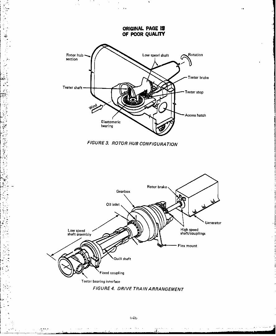
.. Pre-rotation activities included drive train alignments (possible onlyC" after the weight of the rotor is installed on the nacelle) and rotor

•.':"_.,. strain gage calibrations. Integration testing of the completed machine.... was then accomplished. This test series included home of the same

-_,,-.

or tests run on the ground, but with a complete system and all of the

operational sensors installed. End-to-end testing of the engineering

instrumentation system from the transducers throagh to the NASA

,.._. Mobile Data System (MDS) was also accomplished. A final pre-rotation

confidence test was then run prior to committing the machine to wind-

_;,: powered tests._..

°_°" Wind-powered tests are comprised of checkout and acceptance tests.

On WTS i, a series of qualification tests was also run to satisfyr_.'"

_,, those system qualification test requirements which could only be

_i]' accomplished during wind-powered tests. After wind-powered operation!Oo._;" was verified during the checkout test, acceptance tests were run to

_,i- demonstrate that the machine is fully operable and ready for acceptance.

i:iii,i,.' Included in these tests were wind-powered operation for i00 hours,-?':!..,,. operation through various operating regimes, specified numbers of

_?.., start/stop cycles, demonstration of fail safe system operations, and_',. '> operability demonstrations of'all WTS systems.

:_

#'_° WTS I and WTS 2 he.d completed acceptance test requirements, and WTS 3

had complete.d 50% of acceptance test requirements.

]i,,i; CURRENT SITE STATUS

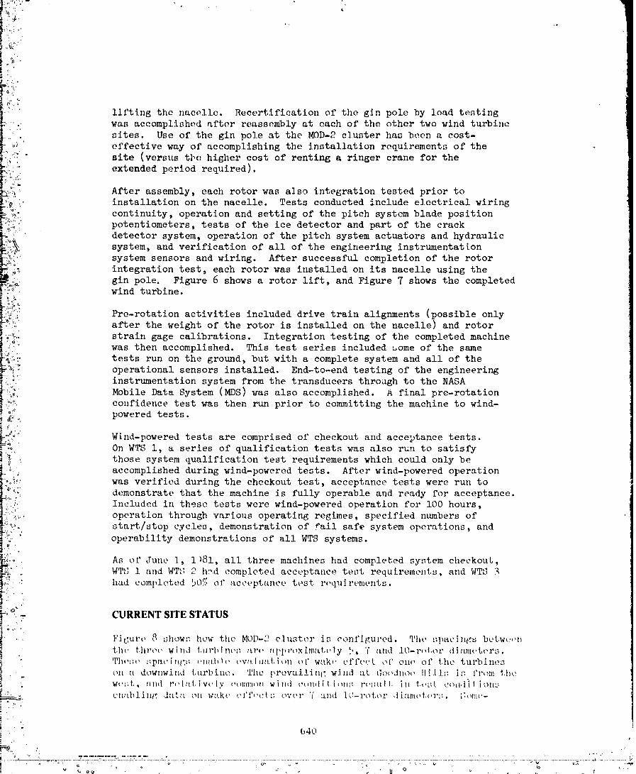
F'igurt, 8 show',: how the MOD-2 cluster is configured. The ,_lU_Cings betw_,,n

'. the tht'c't' wind t,ul'blntu_ :l.r_, upproxlm:_t,l,ly 5, '( alld 10-r_d,or diamcI, crs.

! 'I'}1_':3,' ,,:pat" i tiC:i; i,ii[[b !l, t,v:t Ilia[, i Oll t_t' wak,_ cl'l't'_._t oF o11(" oi" the tul'l?ineson a downwind turbine. The prevailinl: wind at, th-)_,dno_, 11,,'.1]/: i:-: 1'1_Olll_,}|t,.

) ' .

_0. wc;:t,, and r,,l:tI, iw,ly i,ol;liI|clll wind c¢,tld[t.i_ll|:: r_,::lll[, ill t,,.Jt, cihl,i.[I]Oll[:__ cn:d_ling d.'_tta oI| w'tk,., ,,I'f,c_.; ov('l ° '1' :llld l(I--l'Ol, Ol" ,l[alnt,I.(,1 °,: . [;of:it,-

: " 640t

-_ ..... _- - -_: ,_ :-:: ::: .......... _, : :i: ' o;; " _, ..... {7 ..... : - • ; :.4:: ;: i., . ............ : "" _ ..... _.[i_ ............. --,._

O0000007-TSF06

OF POORQUALITY

what fewer but tLdequate opportun]tlos _Lre available for test+the; at

5-rni,or dJamotcrs. The ]ocation of tile two met towers wtm optim:ized

": to assure that at ]ca:d,one, and usually both, of the met tower,n

' receLve unperturbed wind durint_ required test conditions.

b_lltlple operat, ion of all t,hree m_tellilleswas first accomplished in

May, 1981, initiating MOD-2 cluster operation. Both of the met towers

and tlle BPA substation }lad been installed and checked out earlier and

;"' were oper_ttl,m;tl. Construction equipment had been removed and the

'" gin pole disasqembled arld stored on site.

The nature of the testing of the MOD-2 cluster, including aerodynamic

wake effects of multiple wind turbines, requires simultaneous record-

ing of instrumentation on all three machines as well as met tower

•:, data. The MOD-2 intersite data system was designed, installed and

> checked out to accomplish this objective. _te data collection center

for this system is housed in a 3 by 4.5 meter (I0 by 15 foot) building

. adjacent to WTS 2. Operation of the data center was initiated in

April, 1981, and the capability is provided to record and displaydata from the three wind turbines and the two met towers. In addition

to recording analog tapes for data analys_s, tile data center also houses

two computers for formating data to be sent to BPA and the Battel]e

.. Northwest Laborato:-y. Strip chart recorders, a line printer, and a

,." CRT preseut real time data displays to enable test control. A patch

• (. panel is illeltided tO permit data acees/_ to organizations requestingtest data. To facility post-test processing., all of the data is

recorded on a sing.le tape recorder wi%,h a eoltmtotltime base.

Engineering, data is collected on each wind turbine using, the Engineer-

[ng Instrumentation System (EIS) de.slgued and installed as part of tile

: NASA data system used on all NASA large wind turbines. This system

employs one rotating FM multiplexer mounted on tile low speed shaft

+_ and one FM multiplexer mounted on the nacelle wall to multiplex

' q. total of 04 channels at, tiny one time. A total of 80 transducers

are available on each machine and up to 40 may be selected for

c lu._ter tests. During qualification, checkout testing, add acceptance

testin£: of the ind[v_du'_l wind turbines, the NASA-provided Mobile

D_tta System (MDS) was used for data reeordizl_; and display. Having

:;ub._t,etni,ially completed t,hesc activities, the b_S h'ts been released

... l'or oth:,r NASA t,rogram:;.

Blc,tdat,:_ :tt+_' :l.],'.;c,tF:tll:;m.['{,tc'd.l'romi:]l(,l+.w:'>IIlOtfowl,r:: to _,iI¢,d'tta

center. Tvam:mi-:::tou _,i" a.ll of the data tu the data center :,:

:,+c,.'omt,lish.e,i ttqitt+: :'it,t,t' opt, it':; t.o pt't,t,l.ttd, tht, pos.;il, ii. ity off

---:" t'lt'ct.rit'tt] int,,l'ft, rt,uc_, l'.t'onl tht" adjttt't,ttL bur:ted power outp'ttt cttble+.;which art, .loctl,ted _l t+t,wPut'lift;|']'oln+,}it'I?M (anti]t+,,:)d,+ti.:tc.tblt,t;(see

I; l+'lc,ure :_ For alu+roxituatt, c+tbh, t+,,utlug,).

+

).t

t+,l 1

..... '%J=:" I_ _" • " ' •

O0000007-TSF07

PRELIMINARY TEST RESULTS

Table 2 summarizes operation of the three wind turbines to date.

: During the majority of the checkout and acceptance testing period ofeach wind turbine, the MDS as well as most of test team, was required

,!,, for testing. One hundred hours of operating time are required for

.i: completion of the test requirements for each machine. As of June i,1981, the hundred-hour requirements had been met for WTS 1 and 2,

and test emphasis was shifted to WTS 3.

Substantial early wind power testing was accomplished on WTS 1 prior

_ to attempting to synchronize with the utility. A lesser period of

presynchronization test time was accomplished on WTS 2. Satisfaction.... of the presync test requirements during testing on WTS 1 and WTS 2

i:'_ has resulted in relatively short periods of nonsync operation on WTS 3.

_/_•. During normal automatic operations, synchronization with the utility

_"_' is usually accomplished in less than two minutes after reaching rated

-" speed. Power generated has averaged between 1000 kw and 2000 kw

_7_" during testing, although all three machines have operated over the

_. power spectrum from 100 kw to above rated (2500 kw). In late May,

/ 1981, all three machines were simultaneously operated on-line with_:_: no problems.

o'_ Test data obtained on all three machines have been used to verify the_,'_ MOD-2 design, satisfy checkout and most _f the acceptance test require-

....,o ments for the cluster, and make suitable adjustments to subsystemsto optimize the operation of each machine. Noteworthy are the control

L', system improvements that have resulted in significantly improving

"'" power quality (assuring that power output is relatively insensitive

to wind gusts) and significantly reducing tower and rotor loads by_ '. use of a notch filter and optimizing the gain setting.

Preliminary test data on power output versus wind speed is shown in"' Figure 9. The data points are relatively well grouped showing consistent

data over several days of operation. The data is shifted to the rightcompared to the design curve, but optimization of power output versus

':_ wind speed (controlled blade position versus wind speed) has not yet

"_• been accomplished. Detailed analysis must yet be accomplished to-_ verify the preliminary data.

o

,,', FUTURE PLANS/ACTIVITY

" = Continuing activities at the Goldendale site will include completion.$/:.... of acceptance test requirements on WTS 3 and formal NASA acceptance

•_" of all three wind turbines. These actions will be accomplished in

concert with BPA assumption of normal operation and maintenance

,." functions, and commencement of a two-year test and evaluation program.This two-year program will be conducted as a Joint government/industry

'-. team effort with specific activities planned and controlled by aworking group chaired by NASA LeRC and comprised of BPA, NASA, BEC

and Battelle representatives. The scope of effort under th_s program

%.

542

V

.........................................................................'....................... 00000007-

o ."

"-/, ,i_

•. will encompass special tests (nolse, TV Interference, aerodynamic

i-__: wake effects, utility interface); hardware product improvements;

....• performance optimization and improvements; system availability

-_i) and maintainability evaluation; implementation of performance,/ maintenance, and reliability data collection systems; _'eflnements/

_,,:/ improvements to operating and maintenance procedures; and development-,,,', of a cost-effective supply support program.

.... o.

:_._."" The ultimate goal is to achieve maximum commercial viability of the

_?_/° MOD-2 wind turbine through knowledge and experience gained from the,_'_'"": Goldendale installation.

7-'' ):,-

i _;__"

i _°/'i •

. :"..

/

. L

; 643

O0000007-TSF09

ORIGINAL PAG_ ISOF POOR QUALITY

, TABLE 1. PROGRAMMILESTONES

• Go.ahead August1977• Conceptualdesigncomplete July 1978• Preliminarydesigncomplete November1978• Detail designcomplete May 1979

; • Fabricationstart June1979• Site selectionfor first threeunits. October1979• Firstunit

_., : • Start site preparation March 1980• Site performancecomplete June 1980• Componentfabricationcomplete July 1980

":" • Tower installationcomplete August 1980• Nacelleintegrationandtestscomplete_ August1980

' ' ' • Installation complete October1980• Initial rotation November1980

'.'-- • Synchronizedpower production December1980:_.__

:; • Secondunit• Installationcomplete March 1981

: _' • Third unit

,;: • Installation complete May 1981• Fourth unit

:. • MedicineBowsiteselected April 1981": • Installation complete December1981

,i

TABLE 2. MOD-2 OPERATIONSSUMMARY.-!

_ Operatingtime Time On-Line PowerGenerated(hours) (hours) (KWH)

i.

WTS No.1 107 84 99,400

: WTS No.2 122 112 138,000

WTS No.3 19 18 24,000i"

!'/Total 248 214 261,400

:,:.

(_,t,1

O0000007-TSFIO

ORIGINAL PA_ I8OF POOR QUALITY

___ Ratedpower 2,500 kW

; l 45 ft_ I_,f--- Controllabletip Rotordiameter _ 91,4m (300 ft)

•: J -- _ Teeteredrotor Rotor type . Teetered- tip control. Rotor orientation __ Upwind. _1_ 288 in Rotor airfoil .__ NACA 230XX

30O-ft die It 114 in Ratedwind @hub __ 12.2 m/s (27.5 mph).;'! _445 in _ Cut-off wind speed@hub

_ Wind _ t Goldendaleunits __ 20.1 m/s (45 mph)• _ / $ MedicineBowunit . 26.8 m/s (60 mph)!' _- Teeteraxis JJJ_Nacelle 200 ft Rotortip speed_ 83.8 m/s (275 ft/sec): j_l_Tower Rotorrpm 17.5

" _,i------- 120-in O.D.:' Generatorrpm _ 1,800

' II1%/Fieldsplices Generatortype _ Synchronous"_, Ill/ Fieldsplices Gearbox . Compactplanetarygear

--=:_'_ 50 ft _. _,,,_ (4 places) Hub height 61m (200 ft)

° LE--_.; _ "=" 250-in O.D. Tower Soft-shelltypePitchcontrol ._ Hydraulic

-_:_ Foundation_ _1 804-in octagon Yaw control Hydraulic_. _ - I Electroniccontrol _ Microprocessor

:_" FIGURE 1. MOD-2 CONFIGURATION FEATURES AND CHARACTERISTICS

_ _/,: ^e,_,*_\_0_

• _ov

i:__ _j/,,, _

_" L linnet --J F Pitch control actuator

.:_" _"-.._e_ix-_-.,_ "_ /-Bolted splice: "" _'#,_ e_,__ _ Rotation

--'_ - 75 ft-.v#e"")_ 1"_ C.W. viewed

" Mid-section .... ""-_t / "_',_ - _--_ ii" "_rom up wind': ,../ "_ _e_,.

: Upperblade -" ¢_#_'

- surf,oo Hub section-_

j FIGURE 2. ROTOR BLADE CONFIGURA T/ON

• 645

O0000007-TS F11

'" ORIGINALPAGEIgi _ OF POORQUALITYi

t

Rotor hub Low _peod shaft %otatlon_..-, seotion

•_; brake|

• • ,.. Teeter

" ,.._" stop

: "_:" hatch

L_:.; Elastomeric; _}_, bearing

4_' FIGURE 3. ROTOR HUB CONFIGURA T/ON

_-:_.

_o

_)_".'! "'" Rotor brak(

',° _ Gearbox l

i_._;:. Oilio,et i_:.,7 1:°:"; 2!

:, Generator ,!_.o_

•,,'i...: Low speed High speed 'i_. "' shaft assembly shaft/couplings

.. ,.. Flex mount _

i----:!- ,h,,t "i

... Fixed coupling

Teeter bearing interface ._

i :i"_:i':;_.' FIGURE 4. DRIVE TRAIN ARRANGEMENT

i ,

i "

04b

O0000007-TSF12

OF POORQUiddITY

Rotor N_mlle TowQr_nd Fa_llity

t', t - II ,otograt,on,os,I [ '°to,r"'lon'o"l

i -I I• Installotloni

_" I Calibrationsand Iallgnmonts ,]

=' Pro.RotationTests f

"-" I Integrationtest i

; and pre.rotatlon I

:_" confidencetest IT

Wind PoweredTests [ I Checkout_test II Acceptancetest I

:.. FIGURE 5. MOD.2 WTS SYSTEM TEST FLOW

• 647

............ " LI......" i," • ...................................::_ ............_._,,_J

O0000007-TSF13

FIGURE 6. MOD-2 INSTALLATION

: ORIGINAL PAG_ " _

i-::_ BLACK AND WHITE PHOTO(]RAP_I,

""I" . 648

O0000007-TSF14

FIGURE 7. MOD-2 WIND TURBINE

;._' ,',, 649

00000007-TSG01

, te ,_1

__" OF POOR QUALITY- ,,',L

'

Unit hl....'., Nort

"". Prevalllng 2,015.fti _: wind

! _ Data (:able} _ _ 10505.ft Data

_= _ Data Center Acce.

i / ¢abh road

._ • Power Uniti ,_" Met tower substation 1

_" _ 2

i -4

i,,. Met tower.. 1 J

._ . L

Unit',_; 3

": Goldendale, _-

_' Washington Statehighway8

-,,.. FIGURE 8. SITE PLAN (INCLUDING DATA ACQUISITION SYSTEM)

i.J':_ 2,500

' ' ' "_,000 MemumdonWTS2Averagingtime., 10minute=} ::. i SyltO StaftdMd lea level conditions! _ powerL,/...°, (kW) 1,500 • 4 May1981

• 6 May1981j B 7 May1981__:"'_,% 1,000 * 9 May1981

[.%,i $ 10May1981i _ • 11May1981

" 600

i,v.l,... II

b "' O_." 10 18 20 28 30 35 40 45

-, Windspeedet MetTower2 (mphet 198ft)

_'_ FIGURE 9. VARIATION OF MOD-2 POWER OUTPUT WITH WIND SPEED

'

i - _50

O0000007-TSG02


Recommended